

Page 1

TW100-BRF104
Broadband Router + Firewall
User’s Guide
Version 1.00
November 2001
Page 2

TW100-BRF104 Broadband Router+Firewall
Table of Contents
List of Figures............................................................................................................................................ iv
List of Tables.............................................................................................................................................vi
1.1 About the TW100-BRF104 Broadband Router+Firewall............................................................1-1
1.2 Key Features ................................................................................................................................ 1-1
1.3 Features in Detail.........................................................................................................................1-2
1.4 Application ..................................................................................................................................1-6
2.1 Package Contents......................................................................................................................... 2-1
2.2 System Requirements ..................................................................................................................2-1
2.3 TW100-BRF104 Broadband Router+Firewall Front Panel ......................................................... 2-2
2.4 TW100-BRF104 Broadband Router+Firewall Back Panel..........................................................2-2
2.5 Connecting the Broadband Router+Firewall ...............................................................................2-3
2.6 Back to Factory Defaults .............................................................................................................2-4
3.1 Introduction..................................................................................................................................3-1
3.2 Preparing Your Personal Computers for IP Networking .............................................................3-1
3.3 Configuring Windows 95 or later for IP Networking .................................................................. 3-2
3.4 Configuring the Macintosh for IP Networking............................................................................3-4
3.5 Your Internet Account .................................................................................................................3-6
3.6 Ready For TW100-BRF104 Broadband Router+Firewall Configuration....................................3-8
4.1 Web Configurator And Browsers ................................................................................................4-1
4.2 Introducing The Embedded Web Configurator............................................................................4-2
5.1 Setup ............................................................................................................................................ 5-1
5.2 System .........................................................................................................................................5-5
5.3 LAN Setup...................................................................................................................................5-6
5.4 Status ...........................................................................................................................................5-9
6.1 Dynamic DNS..............................................................................................................................6-1
ii Table Of Contents
Page 3

6.2 Port Forwarding ...........................................................................................................................6-3
6.3 Static Route..................................................................................................................................6-6
6.4 Dynamic Route ..........................................................................................................................6-10
6.5 Upgrade and Backup..................................................................................................................6-12
6.6 Remote Management .................................................................................................................6-16
6.7 Diagnostic ..................................................................................................................................6-19
7.1 Security Management ..................................................................................................................7-1
7.2 Web Patrol ...................................................................................................................................7-4
7.3 Services........................................................................................................................................7-7
7.4 Log ...............................................................................................................................................7-9
8.1 Problem Scenarios........................................................................................................................8-1
8.2 FAQ .............................................................................................................................................8-3
Table Of Contents iii
Page 4

TW100-BRF104 Broadband Router+Firewall
List of Figures
Figure 1-1 Broadband Router+Firewall Application...................................................................................1-6
Figure 3-1 Configuring Windows for IP Networking..................................................................................3-2
Figure 3-2 Macintosh TCP/IP......................................................................................................................3-5
Figure 3-3 Verifying Macintosh TCP/IP .....................................................................................................3-5
Figure 4-1 Login Window ...........................................................................................................................4-2
Figure 4-2 Embedded Web Configurator Home..........................................................................................4-3
Figure 5-1 WAN Setup................................................................................................................................5-2
Figure 5-2 System Setup..............................................................................................................................5-5
Figure 5-3 LAN Setup .................................................................................................................................5-7
Figure 5-4 DHCP Client Table ..................................................................................................................5-88
Figure 5-5 Status Screen............................................................................................................................5-99
Figure 5-6 Statistics Screen .....................................................................................................................5-111
Figure 6-1 Dynamic DNS Setup.................................................................................................................. 6-2
Figure 6-2 Port Forwarding .........................................................................................................................6-5
Figure 6-3 Static Route................................................................................................................................6-7
Figure 6-4 Show Routing Table...................................................................................................................6-9
Figure 6-5 Dynamic Route ........................................................................................................................6-11
Figure 6-6 Upgrade and Backup................................................................................................................6-12
Figure 6-7 Upgrade System Software........................................................................................................6-13
Figure 6-8 Restore Factory Default Configurations ..................................................................................6-14
Figure 6-9 Backup Current Configurations ...............................................................................................6-15
Figure 6-10 Restore Previously Saved Configurations..............................................................................6-15
Figure 6-11 Remote Management .............................................................................................................6-17
Figure 6-12 Diagnostic ............................................................................................................................6-179
Figure 7-1 Security Management ................................................................................................................7-2
iv List of Figures
Page 5

Figure 7-2 Web Patrol..................................................................................................................................7-5
Figure 7-3 Services ....................................................................................................................................7-58
Figure 7-4 Security/Services Event Log ..................................................................................................7-510
Figure 7-5 Web Patrol Log ......................................................................................................................7-512
List of Figures v
Page 6

TW100-BRF104 Broadband Router+Firewall
List of Tables
Table 2-1 Front Panel LEDs........................................................................................................................2-2
Table 2-2 Back Panel Connectors................................................................................................................2-2
Table 5-1 WAN Setup .................................................................................................................................5-3
Table 5-2 System Setup...............................................................................................................................5-6
Table 5-3 LAN Setup...................................................................................................................................5-7
Table 5-4 DHCP Client Table .....................................................................................................................5-9
Table 5-5 Status Screen ...........................................................................................................................5-100
Table 5-6 Statistics Screen.......................................................................................................................5-111
Table 6-1 Dynamic DNS Setup ...................................................................................................................6-2
Table 6-2 Port Table Entries (Example) ...................................................................................................... 6-4
Table 6-3 Port Forwarding...........................................................................................................................6-6
Table 6-4 Static Route .................................................................................................................................6-8
Table 6-5 Show Static Routing Table........................................................................................................ 6-10
Table 6-6 Dynamic Route..........................................................................................................................6-11
Table 6-7 Upgrade and Backup .................................................................................................................6-13
Table 6-8 Remote Management.................................................................................................................6-18
Table 6-9 Diagnostic..............................................................................................................................6-1820
Table 7-1 Security Management..................................................................................................................7-3
Table 7-2 Web Patrol................................................................................................................................... 7-6
Table 7-3 Services .....................................................................................................................................7-69
Table 7-4 Security/Services Event Log ...................................................................................................7-611
Table 7-5 Web Patrol Log .......................................................................................................................7-612
vi List of Tables
Page 7

TW100-BRF104 Broadband Router+Firewall
Chapter 1
Introduction
1.1 About the TW100-BRF104 Broadband Router+Firewall
The TW100-BRF104 Broadband Router+Firewall provides continuous, high-speed 11 Mbps access
between your Ethernet devices. In addition, it connects your entire network to the Internet through an
external broadband access device (such as a cable modem or DSL modem) that is normally intended for
use by a single computer.
The TW100-BRF104 Broadband Router+Firewall provides you with multiple Web Patrol options, plus
browsing activity reporting and instant alerts - both via e-mail. Parents and network administrators can
establish restricted access policies based on time-of-day, Website addresses and address keywords, and
share high-speed cable/DSL Internet access for up to 253 personal computers. Network Address
Translation (NAT) and DoS prevention protects you from hackers.
With minimum setup, you can install and use the Broadband Router+Firewall within minutes.
1.2 Key Features
Built in 4-port LAN 10/100 Mbps Ethernet UTP Switch
• Half-duplex or full-duplex operation
• Allows LAN connections at 10 megabits per second (Mbps) or 100 Mbps
• Auto sensing Ethernet (10BASE-T) or Fast Ethernet (100BASE-Tx) transmissions
th
• Normal/uplink selective switch at the 4
One Ethernet UTP port for WAN connection
• Ethernet connection to a wide area network (WAN) device, such as a cable modem or DSL
modem
Embedded FTP Server for firmware upgrade
Embedded FTP Server configuration backup and restore
Scripting and spoofing for major cable providers
Restore Factory Defaults Button to reset to factory default IP address, password, and other
configurations
Introduction 1-1
LAN port
Page 8

TW100-BRF104 Broadband Router+Firewall
Embedded Web Configurator for easy setup and management
Security
• DoS (Denial of Service) prevention
• SPI (Stateful Packet Inspection)
• Applications Services Management
• Login capability
• Web browsing Patrol by using URL keyword blocking
• Auditing and e-mail reporting of web browsing activities
• Network Address Translation (NAT) hides local computers from the Internet
• Powerful packet filtering capabilities
• Incoming port forwarding and DMZ for specific services
Protocol Support
• IP routing
• Dynamic extended Network Address Translation (NAT+) with port forwarding for operation
with a single static or dynamic IP address
• Dynamic Host Configuration Protocol (DHCP) server for dynamically assigning network
configuration information to computers on the LAN
• DHCP client for dynamically obtaining configuration information from the Internet Service
Provider (ISP)
• DNS Proxy for simplified configuration
• PPP over Ethernet (PPPoE) support
• PPTP support
1.3 Features in Detail
1.3.1 NAT Implementation
The implementation of NAT allows for specific ports redirection, and provides support for the following
“NAT-unfriendly” applications:
• NetMeeting
1-2 Introduction
Page 9

TW100-BRF104 Broadband Router+Firewall
• CuSeeMe
• Microsoft PPTP client
• Microsoft Traceroute
• RealAudio
• VDOlive
• IRC
• ICQ
• Quake, Quake variants, and other popular games
• Port Forwarding
The Broadband Router+Firewall also allows VPN (IPSec & PPTP) packets to pass though NAT.
1.3.2 Scripting Requirements
The TW100-BRF104 Broadband Router+Firewall supports login scripting and monitoring requirements for
major cable modem deployments such as RoadRunner.
1.3.3 Security
The TW100-BRF104 Broadband Router+Firewall is equipped with several features designed to maintain
security, as described in this section.
Password Security
PAP and CHAP support (RFC 1334 plus major vendor variations) if required in login script.
Computers Hidden By NAT
Network address translation (NAT) opens a temporary path to the Internet for requests originating
from the local network. Requests originating from outside the LAN are discarded, preventing
users outside the LAN from finding and directly accessing the computers on the LAN.
Port Forwarding With NAT
Although NAT prevents Internet locations from directly accessing the computers on the LAN, the
Broadband Router+Firewall allows you to direct incoming traffic to specific computers based on
the service port number of the incoming request, or to one designated “DMZ” host computer.
1.3.4 Firewall
Access Control (Application Services Management)
Block selected application services, such as ICQ, MSN messenger, on-line games, and so on.
Introduction 1-3
Page 10

TW100-BRF104 Broadband Router+Firewall
DoS (Denial Of Service) Prevention
Protect the devices in the LAN from hacker attacks.
Real Time Alert
While services are to access, or hacker attempt to attack, a real time alert via email will be sent
to the assigned administrator.
Schedule
The TW100-BRF104 allows the user to specify the day and time to blocking.
Trusted Host
The TW100-BRF104 allows the user to specify one Trusted host from blocking by the fixed IP
address.
Periodical Reports And Logs
• The Security events and services activities will be recorded sequentially. The log will
always keep the latest 128 entries.
• The log can be sent to the assigned administrator via email by weekly, daily, or every
periodical report page.
1.3.5 Web Patrol
With its Web Patrol features, the TW100-BRF104 Broadband Router+Firewall prevents objectionable web
contents from reaching your computers. Its Web Patrol features include:
Web Patrol By Domain Or Keyword
The TW100-BRF104 uses Web Patrol to enforce your network’s Internet access policies. The
Broadband Router+Firewall allows you to control access to Internet content by screening for
keywords within Web URLs.
Alert Of Inappropriate Use
You can configure the Broadband Router+Firewall to send an immediate alert e-mail message to
you whenever a local user attempts to access a blocked Web site.
Schedule
The TW100-BRF104 allows the user to specify the day and time to blocking.
Trusted Host
The TW100-BRF104 allows the user to specify one Trusted host from blocking by the fixed IP
address.
Periodical Reports And Logs
1-4 Introduction
Page 11

TW100-BRF104 Broadband Router+Firewall
• The URL of websites visited will be recorded sequentially. The log will always keep the
latest 128 websites entries. The string of each entry should be no more than 128 bytes.
• The log of websites visited can be sent to the assigned administrator via email by weekly,
daily, or every periodical report page included the latest 128 websites visited list.
1.3.6 Auto-sensing 10/100 Ethernet
With its internal, 4-port 10/100 switch, The TW100-BRF104 Broadband Router+Firewall can connect to
either a 10 Mbps standard Ethernet network or a 100 Mbps Fast Ethernet network. The local LAN interface
is auto-sensing and is capable of full-duplex or half-duplex operation.
The TW100-BRF104 Broadband Router+Firewall provides a Normal/Uplink button. By pushing the button
once, the 4
'uplink' connection (e.g. connecting to a Broadband Router+Firewall, switch, or hub).
th
Local Ethernet port can have either a 'normal' connection (e.g. connecting to a computer) or an
1.3.7 TCP/IP
The TW100-BRF104 Broadband Router+Firewall supports the Transmission Control Protocol/Internet
Protocol (TCP/IP) and Routing Information Protocol (RIP).
IP Address Masquerading By Dynamic NAT+
The TW100-BRF104 Broadband Router+Firewall allows several networked computers to share an
Internet account using only a single IP address, which may be statically or dynamically assigned by
your Internet service provider (ISP). This technique, an extension of Network Address Translation
(NAT), is also known as IP address masquerading and allows the use of an inexpensive single-user
ISP account.
Automatic Configuration Of Attached Computers By DHCP
The TW100-BRF104 Broadband Router+Firewall dynamically assigns network configuration
information, including IP, gateway, and domain name server (DNS) addresses, to attached computers
on the LAN using the Dynamic Host Configuration Protocol (DHCP). This feature greatly simplifies
configuration of LAN-attached computers.
DNS Proxy
When DHCP is enabled and no DNS addresses are specified, the Broadband Router+Firewall
provides its own address as a DNS server to the attached computers. The Broadband Router+Firewall
obtains actual DNS addresses from the ISP during connection setup and forwards DNS requests from
the LAN.
PPP Over Ethernet (PPPoE) And PPTP
PPP over Ethernet and PPTP are protocols for connecting remote hosts to the Internet over an
always-on connection by simulating a dial-up connection.
Introduction 1-5
Page 12
TW100-BRF104 Broadband Router+Firewall
1.3.8 Easy Installation and Management
You can install, configure, and operate the TW100-BRF104 Broadband Router+Firewall within minutes
after connecting it to the network. The following features simplify installation and management tasks:
Web Configurator
The Web Configurator allows you to easily configure your Broadband Router+Firewall from
almost any type of personal computer, such as Windows, Macintosh, or Linux.
Visual Monitoring
The TW100-BRF104 Broadband Router+Firewall front panel LEDs provide an easy way to
monitor its status and activity.
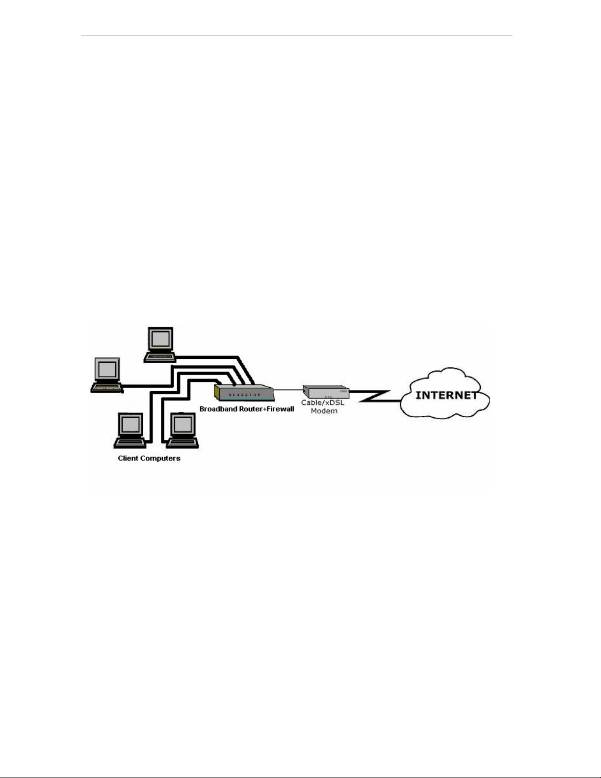
1.4 Application
The TW100-BRF104 Broadband Router+Firewall is a small-office or home-office device that allows a
small LAN to access the Internet or a remote office through an external single-host device such as a cable
modem or xDSL modem. By integrating NAT and DoS prevention, TW100-BRF104 provides not only the
ease of installation and Internet access, but also the most completed security solution to protect your
intranet and efficient network management for data traffic.
The TW100-BRF104 has four single auto-sensing 10/100BASE-T Ethernet ports for connection to the
user’s local network, and a single 10BASE-T port for connection to an external WAN-access device.
Figure 1-1 Broadband Router+Firewall Application
1-6 Introduction
Page 13

TW100-BRF104 Broadband Router+Firewall
Chapter 2
Hardware Setup
2.1 Package Contents
The product package should contain the following items:
The Broadband Router+Firewall
User’s Guide on the CD-ROM
Quick Installation Guide (in print)
5VDC, 2.4A power adaptor
One straight-through category 5 Ethernet cable
If any of the parts are incorrect, missing, or damaged, contact your dealer. Keep the box, sleeve, including
the original packing materials, in case you need to return the Broadband Router+Firewall for repair.
2.2 System Requirements
The TW100-BRF104 Broadband Router+Firewall is intended for use in a network of personal computers
that are interconnected by twisted-pair Ethernet cables.
2.2.1 Computer Requirements
To install and run the TW100-BRF104 Broadband Router+Firewall over your network of computers, each
computer must have the following:
An Ethernet Network Interface Card (NIC).
For interconnecting your wired Ethernet devices, the TW100-BRF104 Broadband Router+Firewall
provides a 4-port switch capable of either 10 Mbps or 100 Mbps operation. Links operating at 100 Mbps
must be connected with Category 5 cable.
2.2.2 Access Device Requirement
The shared broadband access device (cable modem or DSL modem) must provide a standard 10BASE-T
Ethernet interface.
Hardware Setup 2-1
Page 14

TW100-BRF104 Broadband Router+Firewall
2.3 TW100-BRF104 Broadband Router+Firewall Front Panel
The TW100-BRF104 Broadband Router+Firewall front panel LEDs provide an easy way to monitor its
status and activity.
Table 2-1 Front Panel LEDs
LED LABEL Power Test Internet Local
1 2 3 4
LED COLOR
LED STATUS
Green steady Power On
Green blink N/A Transmitting/Receiving 10 Mbps Transmitting/Receiving
Yellow steady N/A N/A 100 Mbps Link
Yellow blink N/A
OFF Power Off
Green Green
Yellow
Test OK
- Diagnostic: G/Y blinking
reciprocally within 1 min
- Error: G/Y blinking
reciprocally after 1 min
Off
Link 10 Mbps Link
N/A 100 Mbps Transmitting/Receiving
No Connection No Connection
Green Green
Yellow
2.4 TW100-BRF104 Broadband Router+Firewall Back Panel
The TW100-BRF104 Broadband Router+Firewall contains port connections, and power connection. The
rear panel contains the following features:
5 VDC power adapter outlet
Internet Ethernet port for connecting the Broadband Router+Firewall to a cable or DSL modem
Four Local Fast Ethernet ports for connecting the Broadband Router+Firewall to local computers
Normal/Uplink push button for Internet Port and the 4
th
Local Port
Default Restore button
Table 2-2 Back Panel Connectors
BACK PANEL CONNECTOR DESCRIPTION
LAN Ethernet Port Four 10/100M BASE-T RJ-45 connectors
WAN Ethernet Port One RJ-45 10BASE-T connector
Cascade Uplink Switches One uplink switch to set LAN port #4 as normal port or uplink port
2-2 Hardware Setup
Page 15

TW100-BRF104 Broadband Router+Firewall
One uplink switch to set WAN port as normal/uplink
Restore Factory Defaults Button Capable of restoring the factory default settings.
The switch is accessible by inserting a pin through the hole in the rear
panel.
Power Supply 5 VDC at 2.4 Amp Max.
2.5 Connecting the Broadband Router+Firewall
Before using your Broadband Router+Firewall, you need to do the followings:
Connect your local Ethernet network to the LAN port(s) of the Broadband Router+Firewall.
Connect your cable or DSL modem to the WAN port of the Broadband Router+Firewall.
Connect the power adapter.
2.5.1 Connecting to your Local Ethernet Network
The TW100-BRF104 Broadband Router+Firewall incorporates a four-port switch for connection to your
local Ethernet network. The Fast Ethernet ports are marked Local 10/100M, and are capable of operation at
either 10 Mbps (10BASE-T) or 100 Mbps (100BASE-Tx), depending on the Ethernet interface of the
attached computer, hub, or switch. For any connection that will operate at 100 Mbps, you must use a
Category 5 (Cat 5) rated cable, such as the Ethernet cable included with the Broadband Router+Firewall.
Connect up to four computers directly to any of the four LAN ports of the Broadband Router+Firewall
using standard Ethernet cables.
If your local network consists of more than four hosts, you will need to connect your Broadband
Router+Firewall to another hub or switch: Connect any port 4 of your TW100-BRF104 Broadband
Router+Firewall to any port of an Ethernet hub or switch using a standard or crossover Ethernet cable.
2.5.2 Connecting to Your Internet Access Device
To connect the Broadband Router+Firewall to the WAN use the Ethernet cable provided with your cable
modem or DSL modem, connect the Broadband Router+Firewall’s WAN port to the 10BASE-T Ethernet
port on your modem.
The attached modem device must provide a standard 10BASE-T Ethernet connection. The TW100BRF104 Broadband Router+Firewall does not include a cable for this connection. Instead, use the Ethernet
cable provided with your access device or any other standard 10BASE-T Ethernet cable. If you are using a
DSL modem, the modem’s connection to the phone line remains unchanged.
Hardware Setup 2-3
Page 16

TW100-BRF104 Broadband Router+Firewall
The Ethernet cable supplied by your ISP for connecting to your cable or DSL modem may be an Ethernet
crossover cable or a straight-through cable. You can push the normal/uplink button in the Broadband
Router+Firewall to connect the modem well.
2.5.3 Connecting the Power Adapter
To connect the Broadband Router+Firewall to the power adapter:
1. Plug the connector of the power adapter into the 5 VDC adapter outlet on the rear panel of the
Broadband Router+Firewall.
2. Plug the other end of the adapter into a standard wall outlet.
3. Verify that the POWER LED on the Broadband Router+Firewall is light.
2.5.4 Verifying Power and Connections
After applying power to the Broadband Router+Firewall, complete the following steps to verify that power
is correctly applied and that you have the proper connections:
1. When power is first applied, verify that the Power LED is steady on (green and not blinking).
2. After approximately 30~60 seconds, verify that:
The Test LED is steady green on. If this LED is still blinking after one minute, then an
error has occurred. If it is reciprocally blinking with yellow and green within one minute,
the Broadband Router+Firewall is performing self-diagnostic tests.
The Local LEDs are lit green for any local ports that are connected to a 10 Mbps device
and are lit yellow when connected to a 100 Mbps device. These LEDs blink when there is
traffic.
The Internet LED is lit steady green when a link has been established to a connected
device. This LED blinks when there is traffic.
2.6 Back to Factory Defaults
The factory default configuration settings are:
• Web Configurator password is 1234
• The IP address to 192.168.1.1
You can erase the current configuration and restore factory defaults in two ways:
1. Use the Restore Factory Default Configurations function of the Web Configurator.
2-4 Hardware Setup
Page 17

TW100-BRF104 Broadband Router+Firewall
2. Use the Restore Factory Defaults button on the rear panel of the Broadband Router+Firewall.
Use this method for cases when the Web Configurator password or IP address is not known.
2.6.1 Procedure To Use the Restore Factory Defaults Button
1. Press the Restore Factory Defaults button for 10 seconds, and then release it. If the TEST LED
begins to blink, the defaults have been restored and the router is now rebooting. Otherwise, go to
step 2.
2. Disconnect the power from the router.
3. While depressing the Restore Factory Defaults button, reconnect power to the router.
4. Continue to hold the Restore Factory Defaults button. The TEST LED will begin to blink, then
will flicker very quickly after about 10 or 15 seconds. This indicates that the defaults have been
restored and the device is now rebooting.
5. Release the Restore Factory Defaults button and wait for the device to reboot.
You are now ready to begin configuration of your network, as described in the following chapter.
Hardware Setup 2-5
Page 18

Page 19

TW100-BRF104 Broadband Router+Firewall
Chapter 3
Preparing Your Network
3.1 Introduction
This chapter describes how to prepare your computer network to connect to the Internet through the
TW100-BRF104 Broadband Router+Firewall and how to order broadband Internet service from an Internet
service provider (ISP).
3.2 Preparing Your Personal Computers for IP Networking
The TW100-BRF104 Broadband Router+Firewall uses the Transmission Control Protocol/Internet Protocol
(TCP/IP). In order to access the Internet through the Broadband Router+Firewall, each computer on your
network must have TCP/IP installed and selected as the networking protocol.
Most operating systems include the software components you need to install and use TCP/IP on your
computer:
Windows 95 or later (including Windows NT) includes the software components for establishing a
TCP/IP network.
Windows 3.1 does not include a TCP/IP component. You need to purchase a third-party TCP/IP
application.
Macintosh Operating System 7 or later includes the software components for establishing a
TCP/IP network.
All versions of UNIX or Linux include TCP/IP components.
Follow the instructions provided with your operating system or networking software to install TCP/IP on
your computer. Although TCP/IP is built into the Windows operating system (starting with Windows 95),
you need to enable and configure it (see later).
In your IP network, all computers and the Broadband Router+Firewall must be assigned IP addresses. Each
computer must also have certain other IP configuration information such as a subnet mask (netmask), a
domain name server (DNS) address, and a default gateway address. In most cases, you should install
TCP/IP so that the computer obtains its specific network configuration information from a DHCP server
during boot-up.
Preparing Your Network 3-1
Page 20
TW100-BRF104 Broadband Router+Firewall
The TW100-BRF104 Broadband Router+Firewall is shipped pre-configured as a DHCP server. The
gateway assigns the following TCP/IP configuration information automatically when the computers are
rebooted:
Computer IP addresses - 192.168.1.2 through 192.168.1.32
Subnet mask - 255.255.255.0
Gateway address - 192.168.1.1
These addresses are part of the IETF-designated private address range for use in private networks.
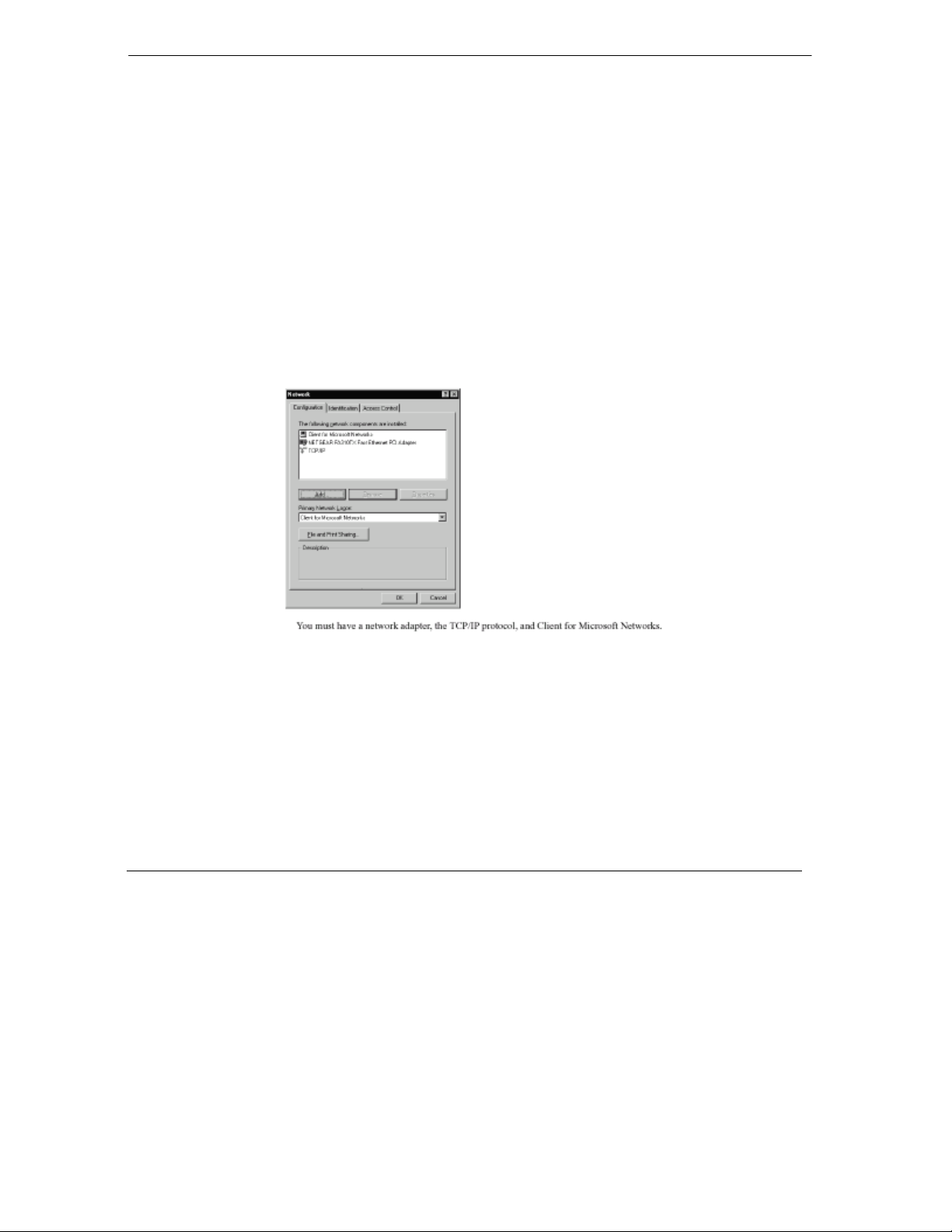
3.3 Configuring Windows 95 or later for IP Networking
As part of the computer preparation process, you need to manually install and configure TCP/IP on each
networked computer. Before starting, locate your Windows CD; you may need to insert it during the
TCP/IP installation process.
Figure 3-1 Configuring Windows for IP Networking
3.3.1 To configure Microsoft Windows 95 or later for IP networking:
1. On the Windows taskbar, click the Start button, point to Settings, and then click Control Panel.
2. Double-click the Network icon.
The Network window opens, which displays a list of installed components:
You must have a network adapter, the TCP/IP protocol, and Client for Microsoft Networks.
3-2 Preparing Your Network
Page 21

TW100-BRF104 Broadband Router+Firewall
If you need the adapter:
a. Click the Add button.
b. Select Adapter, and then click Add.
c. Select the manufacturer and model of your network adapter, and then click OK.
If you need TCP/IP:
a. Click the Add button.
b. Select Protocol, and then click Add.
c. Select Microsoft.
It is not necessary to remove any other network components shown in the
Network window in order to install the adapter, TCP/IP, or Client for Microsoft
Networks.
d. Select TCP/IP, and then click OK.
If you need Client for Microsoft Networks:
a. Click the Add button.
b. Select Client, and then click Add.
c. Select Microsoft.
d. Select Client for Microsoft Networks, and then click OK.
3. Restart your computer for the changes to take effect.
3.3.2 Configuring TCP/IP Properties
After the TCP/IP protocol components are installed, each computer must be assigned specific information
about itself and resources that are available on its network. The simplest way to configure this information
is to allow the computer to obtain the information from the internal DHCP server of the TW100-BRF104
Broadband Router+Firewall.
If you are using DHCP with the recommended default addresses, you can configure your computers by
following these steps:
1. Install TCP/IP on each computer, leaving the computer configured to obtain configuration settings
automatically (by DHCP).
2. Connect your Ethernet-interfaced computers to the Broadband Router+Firewall.
3. Restart the TW100-BRF104 Broadband Router+Firewall and allow it to boot.
Preparing Your Network 3-3
Page 22

TW100-BRF104 Broadband Router+Firewall
4. Restart each computer.
If an ISP technician configured your computer during the installation of a
broadband modem, or if you configured it using instructions provided by your
ISP, you may need to copy the current configuration information for use in the
configuration of your TW100-BRF104 Broadband Router+Firewall.
3.3.3 Verifying TCP/IP Properties (Windows)
After your computer is configured and has rebooted, you can check the TCP/IP configuration using:
winipcfg.exe for Windows 95, 98, and Millennium utility
ipconfig.exe for Windows NT and Win 2000 Professional systems
To check your computer’s TCP/IP configuration:
1. On the Windows taskbar, click the Start button, and then click Run. The Run window opens.
2. Type
3. Select your network adapter. The window is updated to show your settings, which should match
winipcfg, and then click OK. The IP Configuration window opens, which lists (among
other things), your IP address, subnet mask, and default gateway.
the values below if you are using the default TCP/IP settings:
The IP address is between 192.168.1.2 and 192.168.1.32
The subnet mask is 255.255.255.0
The default gateway is 192.168.1.1
3.4 Configuring the Macintosh for IP Networking
Beginning with Macintosh Operating System 7, TCP/IP is already installed on the Macintosh. On each
networked Macintosh, you will need to configure TCP/IP to use DHCP by following these steps:
1. From the Apple menu, select Control Panels, then TCP/IP. The TCP/IP Control Panel opens:
3-4 Preparing Your Network
Page 23
TW100-BRF104 Broadband Router+Firewall
Figure 3-2 Macintosh TCP/IP
2. From the Connect via box, select your Macintosh’s Ethernet interface.
3. From the Configure box, select Using DHCP Server. You can leave the DHCP Client ID box
empty.
4. Close the TCP/IP Control Panel.
5. Repeat this for each Macintosh on your network.
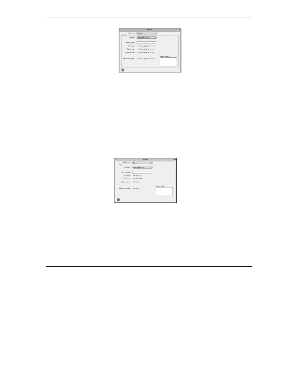
3.4.1 Verifying TCP/IP Properties (Macintosh)
After your Macintosh is configured and has rebooted, you can check the TCP/IP configuration by returning
to the TCP/IP Control Panel. From the Apple menu, select Control Panels, then TCP/IP.
Figure 3-3 Verifying Macintosh TCP/IP
The panel is updated to show your settings, which should match the values below if you are using the
default TCP/IP settings:
The IP Address is between 192.168.1.2 and 192.168.1.32
The Subnet mask is 255.255.255.0
The Broadband Router+Firewall address is 192.168.1.1
Preparing Your Network 3-5
Page 24

TW100-BRF104 Broadband Router+Firewall
If you do not see these values, you may need to restart your Macintosh or you may need to switch the
Configure setting to a different option, then back again to Using DHCP Server.
3.5 Your Internet Account
For access to the Internet, you need to contract with an Internet service provider (ISP) for a single-user
Internet access account using an external broadband access device such as a cable modem or DSL modem.
This modem must be a separate physical box (not a card) and must provide an Ethernet port intended for
connection to a Network Interface Card (NIC) in a computer.
For a single-user Internet account, your ISP supplies TCP/IP configuration information for one computer.
With a typical account, much of the configuration information is dynamically assigned when your
computer is first booted up while connected to the ISP, and you will not need to know that dynamic
information.
In order to share the Internet connection among several computers, your Broadband Router+Firewall takes
the place of the single computer, and you need to configure it with the TCP/IP information that the single
computer would normally use. When the Broadband Router+Firewall’s WAN port is connected to the
broadband modem, the Broadband Router+Firewall appears to be a single computer to the ISP. The
Broadband Router+Firewall then allows the computers on the local network to masquerade as the single
computer to access the Internet through the broadband modem. The method used by the Broadband
Router+Firewall to accomplish this is called Network Address Translation (NAT) or IP masquerading.
3.5.1 Login Protocols
Some ISPs require a special login protocol. In this case, you will need to know what type of protocol is
used, and you will need a login name and password. The two common protocols are:
PPP over Ethernet (PPPoE)
Two common PPPoE clients are WinPOET and EntreNet.
RoadRunner
Not all RoadRunner service areas require a login protocol. If your ISP is RoadRunner, you should
ask whether your computer must run a RoadRunner login program.
After your network and Broadband Router+Firewall are configured, the Broadband Router+Firewall will
perform the login task when needed, and you will no longer need to login from your computer.
3.5.2 Account Information
Unless the ISP dynamically assigns these items, your ISP should give you the following basic information
for your account:
3-6 Preparing Your Network
Page 25

TW100-BRF104 Broadband Router+Firewall
An IP address and subnet mask
A gateway IP address, which is the address of the ISP’s Broadband Router+Firewall
One or more domain name server (DNS) IP addresses
Host name and domain suffix
For example, your account’s full server names may look like this:
example, the domain suffix is
xxx.yyy.com.
mail.xxx.yyy.com. In this
If the ISP dynamically supplies any of these items, your Broadband Router+Firewall automatically acquires
them.
If an ISP technician configured your computer during the installation of the broadband modem, or if you
configured it using instructions provided by your ISP, you need to copy configuration information from
your computer’s Network TCP/IP Properties window (or Macintosh TCP/IP Control Panel) before
reconfiguring your computer for use with the Broadband Router+Firewall. These procedures are described
next.
3.5.3 Obtaining ISP Configuration Information (Windows)
As mentioned above, you may need to collect configuration information from your computer so that you
can use this information when you configure the TW100-BRF104 Broadband Router+Firewall. Following
this procedure is only necessary when your ISP does not dynamically supply the account information.
To get the information you need to configure the Broadband Router+Firewall for Internet access:
1. On the Windows taskbar, click the Start button, point to Settings, and then click Control Panel.
2. Double-click the Network icon.
3. The Network window opens, which displays a list of installed components.
4. Select TCP/IP, and then click Properties.
5. The TCP/IP Properties dialog box opens.
6. Select the IP Address tab.
If an IP address and subnet mask are shown, write down the information. If an address is present,
your account uses a fixed (static) IP address. If no address is present, your account uses a
dynamically-assigned IP address. Click Obtain an IP address automatically.
7. Select the Gateway tab.
If an IP address appears under Installed Gateways, write down the address. This is the ISP’s
gateway address. Select the address and then click Remove to remove the gateway address.
8. Select the DNS Configuration tab.
Preparing Your Network 3-7
Page 26

TW100-BRF104 Broadband Router+Firewall
If any DNS server addresses are shown, write down the addresses. If any information appears in
the Host or Domain information box, write it down. Click Disable DNS.
9. Click OK to save your changes and close the TCP/IP Properties dialog box.
10. You are returned to the Network window.
11. Click OK.
12. Reboot your computer at the prompt. You may also be prompted to insert your Windows CD.
3.5.4 Obtaining ISP Configuration Information (Macintosh)
As mentioned above, you may need to collect configuration information from your Macintosh so that you
can use this information when you configure the TW100-BRF104 Broadband Router+Firewall. Following
this procedure is only necessary when your ISP does not dynamically supply the account information.
To get the information you need to configure the Broadband Router+Firewall for Internet access:
1. From the Apple menu, select Control Panels, then TCP/IP.
2. The TCP/IP Control Panel opens, which displays a list of configuration settings. If the
Configure setting is Using DHCP Server, your account uses a dynamically assigned IP address.
In this case, close the Control Panel and skip the rest of this section.
3. If an IP address and subnet mask are shown, write down the information.
4. If an IP address appears under Broadband Router+Firewall address, write down the address. This
is the ISP’s gateway address.
5. If any Name Server addresses are shown, write down the addresses. These are your ISP’s DNS
addresses.
6. If any information appears in the Search domains information box, write it down.
7. Change the Configure setting to Using DHCP Server.
8. Close the TCP/IP Control Panel.
3.6 Ready For TW100-BRF104 Broadband Router+Firewall
Configuration
After configuring all of your computers for TCP/IP networking and connecting them to the LAN network
of your TW100-BRF104, you are ready to access and configure the Broadband Router+Firewall.
3-8 Preparing Your Network
Page 27

TW100-BRF104 Broadband Router+Firewall
Chapter 4
Introducing The Web Configurator
This chapter introduces the embedded Web configurator and shows you how to log in and perform basic
configuration of your TW100-BRF104 Broadband Router+Firewall. The Web configurator was designed
with ease-of-use paramount yet still allow fine-tuning of the powerful advanced features of the TW100BRF104 Broadband Router+Firewall.
4.1 Web Configurator And Browsers
In order to use the Web Configurator, your computer must have a web browser program installed such as
Microsoft Internet Explorer or Netscape Navigator. Because the embedded Web Configurator uses Java,
your Web browser must be Java-enabled and support HTTP uploads. Free browser programs are readily
available for Windows, Macintosh, or UNIX/Linux.
4.1.1 Logging Into The Web Configurator
1. Turn on the Broadband Router+Firewall and wait for initialization to complete. Allow at least one
minute and verify that the TEST LED is off.
2. Reboot your computer to obtain DHCP configuration from the Broadband Router+Firewall.
3. Launch your web browser.
4. In the Address box of your browser, type http://192.168.1.1 and press ENTER.
5. A login window opens as shown next. This screen may have a different appearance in other
browsers.
Introducing The Web Configurator 4-1
Page 28

TW100-BRF104 Broadband Router+Firewall
TW100-
Figure 4-1 Login Window
6. Type ‘admin’
click OK. If your Broadband Router+Firewall password was previously changed, enter the current
password.
(not case sensitive) in the User Name box, ‘1234’ in the Password box, and then
4.2 Introducing The Embedded Web Configurator
After a successful login you will see the following screen. This page contains hyperlinks to its related setup
page.
4-2 Introducing The Web Configurator
Page 29

TW100-BRF104 Broadband Router+Firewall
Figure 4-2 Embedded Web Configurator Home
The recommended screen resolution is 800 by 600 pixels using small fonts; however you may have to
scroll in some pages where the convenience of having all information displayed in one page outweighs the
inconvenience of scrolling.
The top of the screen has four “buttons”. Click a “button” to see a range of related configuration screens.
1. Home consists of just this screen.
2. Click Basic to set up your WAN, LAN, system information such as name, password and time/date
and display system information and statistics.
Introducing The Web Configurator 4-3
Page 30

TW100-BRF104 Broadband Router+Firewall
3. Click Advanced to configure dynamic DNS, port forwarding, static routes, dynamic routes,
remote management, upload firmware/configuration files and restore/backup configuration files.
4. Click Firewall to configure the firewall including DoS, content filtering, enable/disable services,
scheduling, and display logs.
Click the Help button to see embedded HTML help on the screen.
The next three chapters discuss the setup screens under Basic, Advanced and Firewall.
4-4 Introducing The Web Configurator
Page 31

TW100-BRF104 Broadband Router+Firewall
Chapter 5
The Basic Setup Screens
This chapter discusses how to set up your WAN (Internet), LAN (Local), system information such as name,
password and time/date and display system information and statistics.
5.1 Setup
Click the Setup tab to display the next screen. Use this screen to configure Internet access related setup
options. You may have to scroll down to see the whole screen. The table following the screen describes the
fields displayed in the screen.
The Basic Setup Screens 5-1
Page 32

TW100-BRF104 Broadband Router+Firewall
Figure 5-1 WAN Setup
5-2 The Basic Setup Screens
Page 33

TW100-BRF104 Broadband Router+Firewall
pp
Table 5-1 WAN Setup
FIELD DESCRIPTION
Obtain an IP Address
Automatically
Specify an IP Address Select this option if the assigns a static IP address to the TW100-BRF104 and
IP Address Enter the IP address of this device in dotted decimal notation.
IP Subnet Mask Your TW100-BRF104 will automatically calculate the subnet mask based on
Default Gateway IP
Address
DNS 1, 2 Use DNS (Domain Name System) to map a domain name to its corresponding
Disable Login Select this option if you don’t have to login to access the Internet.
Enable Login Select this option if you have to login to access the Internet then choose which
PPPoE PPPoE is an IETF Draft standard (RFC 2516) specifying how a personal
PPTP Point-to-Point Tunneling Protocol (PPTP) is a network protocol that enables
Select this option if the assigns a dynamic IP address to the TW100-BRF104.
fill in the next four fields.
the IP address that you assign. Unless you are implementing subnetting, use
the computed subnet mask.
Enter the IP address of default gateway in dotted decimal notation. This should
be given to you by your ISP.
IP address and vice versa. The DNS server is extremely important because
without it, you must know the IP address of a machine before you can access
it.
There are two ways that an ISP disseminates the DNS server addresses.
The first is for an ISP to tell a customer the DNS server addresses, usually in
the form of an information sheet, when you sign up. If your ISP gives you the
DNS server addresses, enter them in these fields.
The second is to leave them blank, i.e., 0.0.0.0 — in this case, the TW100BRF104 acts as a DNS proxy.
service fill in its related login service details in the following fields
computer (computer) interacts with a broadband modem (i.e. xDSL, cable,
etc.) connection.
PPPoE provides a login & authentication method that the existing Microsoft
Dial-Up Networking software can activate, and therefore requires no new
learning or procedures for Windows users.
secure transfer of data from a remote client to a private server, creating a
Virtual Private Network (VPN) using TCP/IP-based networks
PPTP su
orts on-demand, multi-protocol, and virtual private networking over
The Basic Setup Screens 5-3
Page 34

TW100-BRF104 Broadband Router+Firewall
FIELD DESCRIPTION
public networks, such as the Internet.
RR-Toshiba
RR-Manager
Username Enter the login name given to you by your ISP.
Password Enter the password associated with the login name above.
Service Name (PPPoE
Only, Optional)
Login Server IP (RR Login
Only)
Idle Timeout (Seconds) This value specifies the idle time (i.e., the length of time there is no traffic from
PPTP Specific
Configuration
My IP Address Enter the IP address of the WAN Ethernet port.
Server IP Address Enter the IP address of the ANT (ADSL Network Termination) modem.
Connection ID/Name Enter the connection ID or connection name in the ANT (ADSL Network
MAC Address Clone
(Optional)
User-defined WAN MAC
Address
Help Click this button for HTML help on this screen.
Apply Click this button to save your changes back to the Broadband Router+Firewall.
Cancel Click this button to cancel any configuration changes you made in this screen.
Choose RoadRunner if your ISP is Time Warner's RoadRunner. Select RR-
Toshiba (RoadRunner Toshiba authentication method) or RR-Manager
(RoadRunner Manager authentication method).
If you need a PPPoE service name to identify and reach the PPPoE server,
enter the PPPoE service name provided to you in the this field.
The TW100-BRF104 will find the RoadRunner Server IP if this field is left blank.
If it does not, then you must enter the authentication server IP address.
the TW100-BRF104 to the remote node) in seconds that can elapse before the
TW100-BRF104 automatically disconnects the login connection. This option
only applies when the TW100-BRF104 initiates the call.
Enter the following information for PPTP login service.
Termination). It must follow the “c:id” and “n:name” format.
This field is optional and depends on the requirements of your xDSL Modem.
The following MAC address field allows users to configure the WAN port's MAC
address by cloning the MAC address from a computer on your LAN. Once it is
successfully configured, the address will be copied to the configuration file. It
will not change unless you change the setting here or upload a different
configuration file.
Enter the MAC Address of the workstation on the LAN whose MAC you are
cloning here.
5-4 The Basic Setup Screens
Page 35

TW100-BRF104 Broadband Router+Firewall
5.2 System
Click the System tab to display the next screen. Use this screen to configure system name, password and
time/date. You may have to scroll down to see the whole screen. The table following the screen describes the
fields displayed in the screen.
Figure 5-2 System Setup
The Basic Setup Screens 5-5
Page 36

TW100-BRF104 Broadband Router+Firewall
Table 5-2 System Setup
FIELD DESCRIPTION
Name
System Name
Domain Name
Password For your first login, enter the default password 1234. As you type the password,
New Password Enter your new system password in this field.
Re-enter To Confirm Re-type your new system password for confirmation.
Time / Date
Time Zone Select the time zone you are in from the drop down list box. This setting will be
Disable Daylight Savings If you are not using daylight savings time, select this option.
Enable Daylight Savings If you use daylight savings time, select this option.
Start Date (month, day) If using daylight savings time, enter the month and day that it starts on.
End Date (month, day) If using daylight savings time, enter the month and day that it ends on
Help Click this button for HTML help on this screen.
Apply Click this button to save your changes back to the Broadband Router+Firewall.
Cancel Click this button to cancel any configuration changes you made in this screen.
System Name is for identification purposes. We recommend you enter your
computer’s “Computer name”.
The Domain Name entry is what is propagated to the DHCP clients on the
LAN. If you leave this field blank, the domain name obtained by DHCP from the
ISP is used. While you must enter the System Name on each individual
computer, the domain name can be assigned from this device via DHCP.
the screen displays an (X) for each character you type.
Please note that if there is no activity for longer than five minutes after you log
in, you will automatically be logged you out and you will see a blank screen.
used for the blocking schedule and also for time-stamping log entries. The
Broadband Router+Firewall uses the Network Time Protocol (NTP) to obtain
the current time and date from one of several Network Time Servers on the
Internet. This menu displays the current time.
5.3 LAN Setup
Click the LAN tab to display the next screen. Use this screen to configure the DHCP server and system
TCP/IP settings. The table following the screen describes the fields displayed in the screen.
5-6 The Basic Setup Screens
Page 37

TW100-BRF104 Broadband Router+Firewall
Figure 5-3 LAN Setup
Table 5-3 LAN Setup
FIELD DESCRIPTION
Disable DHCP Server DHCP (Dynamic Host Configuration Protocol, RFC 2131 and RFC 2132) allows
individual clients to obtain TCP/IP configuration at start-up from a server. You
can configure the Broadband Router+Firewall as a DHCP server or disable it.
Select this field to disable DHCP service. Make sure you have another DHCP
server on your LAN, or else the workstation must be manually configured.
Enable DHCP Server Select this option to configure your Broadband Router+Firewall as a DHCP
server so it will provide the TCP/IP configuration for the clients.
The Basic Setup Screens 5-7
Page 38

TW100-BRF104 Broadband Router+Firewall
FIELD DESCRIPTION
IP Pool Starting Address The Broadband Router+Firewall is pre-configured with a pool of 32 IP
addresses. It allocates 31 IP addresses (excluding the device itself) in the lower
range for other server machines, e.g., server for mail, FTP, telnet, web, etc.,
that you may have.
IP Pool Size This field specifies the size, or count of the IP address pool.
LAN Setup
IP Address Enter the IP address of your Broadband Router+Firewall in dotted decimal
notation
IP Subnet Mask Your Broadband Router+Firewall will automatically calculate the subnet mask
based on the IP address that you assign. Unless you are implementing
subnetting, use the subnet mask computed by the Broadband Router+Firewall.
Help Click this button for HTML help on this screen.
Apply Click this button to save your changes back to the Broadband Router+Firewall.
Cancel Click this button to cancel any configuration changes you made in this screen.
5.3.1 Display DHCP Client Table
Click the Display DHCP Client Table button to pop up the next screen.
Figure 5-4 DHCP Client Table
The DHCP Table shows all IP address assignments that have been made by the Broadband Router+Firewall’s
DHCP server. For each computer client, the table shows the IP address, NetBIOS Host Name, and Ethernet
5-8 The Basic Setup Screens
Page 39

TW100-BRF104 Broadband Router+Firewall
MAC address. If the Broadband Router+Firewall is rebooted, the table data is lost until each PC renews its
DHCP lease.
Table 5-4 DHCP Client Table
FIELD DESCRIPTION
# This is the client index number.
IP Address This is the IP address of the client specified above.
Host Name This is the host name of said client.
MAC Address This is the MAC (Media Access Control) address of said client.
Refresh Click this button to reload the above information.
5.4 Status
Click the Status tab to display the next screen. Use this screen to display system information and statistics.
The table following the screen describes the fields displayed in the screen.
Figure 5-5 Status Screen
The Basic Setup Screens 5-9
Page 40

TW100-BRF104 Broadband Router+Firewall
Table 5-5 Status Screen
FIELD DESCRIPTION
System Information The next five fields display general information about the Broadband
Router+Firewall system.
System Name This is the Broadband Router+Firewall’s system name + domain name
assigned in the System screen. For example, System Name= xxx; Domain
Name= baboo.mickey.com;
Name= xxx.baboo.mickey.com
F/W Version: This is the Networking Operating System firmware version and the date
created, for example, V3.25(CA.1)C0.
System Time
System Date
System Up Time The total time the Broadband Router+Firewall has been on.
WAN Port The next four fields display general information about the Internet Port.
MAC The Internet port Ethernet address.
Subnet Mask The Internet port IP mask.
DHCP
LAN Port The next four fields display general information about the Local Port.
MAC The Local port Ethernet address.
Subnet Mask The Local port IP mask.
DHCP
Show Statistics Click this button to bring up the screen shown next.
Help Click this button for HTML help on this screen.
This displays the current time as set in the System screen.
This displays the current date as set in the System screen.
IP The Internet port IP address.
The Internet port DHCP role (client or none). If set to None, the Broadband
Router+Firewall is configured to use a fixed IP address on the WAN or to use
PPPoE. If set to Client, the Broadband Router+Firewall is configured to obtain
an IP address dynamically from the ISP.
IP The Local port IP address.
The Local port DHCP role (server or none). If set to None, the Broadband
Router+Firewall will not assign IP addresses to local computers on the LAN. If
set to Server, the Broadband Router+Firewall is configured to assign IP
addresses to local computers on the LAN.
5-10 The Basic Setup Screens
Page 41

TW100-BRF104 Broadband Router+Firewall
5.4.1 Statistics
Click the Show Statistics button to bring up the next screen.
Figure 5-6 Statistics Screen
Table 5-6 Statistics Screen
FIELD DESCRIPTION
WAN/LAN The following statistics are displayed for both LAN and WAN respectively.
Port The statistics for the WAN (Internet) and LAN (local) Ethernet ports. For each port,
the screen displays the following information.
Status
TxPkts The number of transmitted packets on this port since reset or manual clear.
RxPkts The number of received packets on this port since reset or manual clear.
Cols The number of collisions on this port since reset or manual clear.
Tx B/s Shows the transmission speed in Bytes per second on this port.
Rx B/s Shows the reception speed in Bytes per second on this port.
Up Time The time elapsed since the last power cycle or reset.
Refresh Click this button to update the screen data.
Shows the port speed and duplex setting if you’re using Ethernet Encapsulation
and Down (line is down), idle (line (ppp) idle), dial (starting to trigger a call) and
drop (dropping a call) if you’re using PPPoE Encapsulation.
The Basic Setup Screens 5-11
Page 42

Page 43

TW100-BRF104 Broadband Router+Firewall
Chapter 6
The Advanced Setup Screens
This chapter discusses how to configure dynamic DNS, port forwarding, static routes, dynamic routes,
backing up/restoring the configuration file, uploading new software, remote management, and Diagnostic.
6.1 Dynamic DNS
Click the Dynamic DNS tab to display the next screen. Use this screen to configure dynamic Domain Name
Server
Your router supports Dynamic Domain Name Service (DDNS). In a Dynamic DNS service, an IP registry
server provides a public central database where dynamically-assigned IP addresses can be stored and
retrieved by hostname lookup. The Dynamic DNS server also stores password-protected e-mail addresses
along with IP addresses and hostnames and accepts queries based on e-mail addresses.
You can update your current dynamic IP address with one or many dynamic DNS services so that anyone can
contact you (in NetMeeting, CU-SeeMe, etc.). You can also access your FTP server or Web site on your own
computer using a DNS-like address (e.g. myhost.dhs.org, where myhost is a name of your choice) which will
never change instead of using an IP address that changes each time you reconnect. Your friends or relatives
will always be able to call you even if they don’t know your IP address.
First of all, you need to have registered a dynamic DNS account with www.dyndns.org. This is for people
with a dynamic IP from their ISP or DHCP server that would still like to have a DNS name.
The Broadband Router+Firewall, at the time of writing, supports the www.dyndns.org client. You can apply
to this client for Dynamic DNS service.
6.1.1 DYNDNS Wildcard
Enabling the wildcard feature for your host causes *.yourhost.dyndns.org to be aliased to the same IP address
as yourhost.dyndns.org. This feature is useful if you want to be able to use for example
www.yourhost.dyndns.org and still reach your hostname.
The table following the figure describes the fields contained within.
The Advanced Setup Screens 6-1
Page 44

TW100-BRF104 Broadband Router+Firewall
Figure 6-1 Dynamic DNS Setup
Table 6-1 Dynamic DNS Setup
FIELD DESCRIPTION
Disable Dynamic DNS
Service
Enable Dynamic DNS
Service
Service Provider This is the name of your Dynamic DNS client. This field is read-only.
Registered Host
Name
Enable Wildcard Your Broadband Router+Firewall supports DYNDNS Wildcard. Select this option to
Select this option to disable Dynamic DNS Service.
Select this option to enable Dynamic DNS Service and then fill in the following fields.
Enter the domain name assigned to your Broadband Router+Firewall by your
Dynamic DNS provider.
6-2 The Advanced Setup Screens
Page 45

TW100-BRF104 Broadband Router+Firewall
FIELD DESCRIPTION
enable DYNDNS Wildcard.
E-mail Address Enter your e-mail address.
User Enter your user name.
Password Enter the password assigned to you.
Help Click this button for HTML help on this screen.
Apply Click this button to save your changes back to the Broadband Router+Firewall.
Cancel Click this button to cancel any configuration changes you made in this screen.
6.2 Port Forwarding
Click the Port Forwarding tab to display the next screen.
6.2.1 Configuring for Port Forwarding to Local Servers
Although the router causes your entire local network to appear as a single machine to the Internet, you can
make local servers for different services (for example, FTP or HTTP) visible and available to the Internet.
This is done using this screen.
Requested services are identified by port numbers in an incoming IP packet. For example, a packet that is
sent to the external IP address of your router and destined for port number 80 is an HTTP (Web server)
request, and port 21 is an FTP request. Examples of port numbers are shown at the top of the PORTS menu,
although you are not limited to these choices.
See IETF RFC1700, “Assigned Numbers,” for port numbers for common protocols.
Many residential broadband ISP accounts do not allow you to run any server
processes (such as a Web or FTP server) from your location. Your ISP may
periodically check for servers and may suspend your account if it discovers any
active services at your location. If you are unsure, refer to the Acceptable Use
Policy of your ISP.
Use this screen to configure the router to forward incoming protocols to IP addresses on your local network
based on the port number. In addition to servers for specific protocols, you can also specify a Default Server
The Advanced Setup Screens 6-3
Page 46

TW100-BRF104 Broadband Router+Firewall
(also called DMZ) to which all other incoming protocols are forwarded. To configure port forwarding to a
local server:
1. Enter a port number in an unused Service Port Range.
2. To forward only one port, enter it again in the Service Port Range after the “~”.
3. To specify a range of ports, enter the last port to be forwarded in this box.
4. Enter the IP address of the local server in the corresponding Server IP Address box.
5. Click Apply at the bottom of the menu.
Local Web and FTP Server Example
If a local computer, with a private address of 192.168.1.33, acts as a Web and FTP server, configure the Port
Forwarding menu to forward ports 80 (HTTP) and 21 (FTP) to local address 192.168.1.33 as shown in the
next table. In order for a remote user to access this server from the Internet, the remote user must know the IP
address that has been assigned by your ISP. If this address is 172.16.1.23, for example, an Internet user can
access your Web server by directing the browser to http://172.16.1.23. The assigned IP address can be found
in the Status Screen, where it is shown as the WAN IP Address.
Some considerations for this application are:
• If your account’s IP address is assigned dynamically by your ISP, the IP address may change
periodically as the DHCP lease expires.
• If the IP address of the local computer is assigned by DHCP, it may change when the computer is
rebooted. To avoid this, change the configuration of your computers to use fixed private addresses
rather than DHCP-assigned addresses.
Table 6-2 Port Table Entries (Example)
PORT # SERVER IP ADDRESS
Default 0.0.0.0
80 (HTTP) 192.168.1.33
21 (FTP) 192.168.1.33
Local computers must access the local server using the computers’ local LAN address (192.168.1.33 in this
example). Attempts by local computers to access the server using the external IP address (172.16.1.23 in this
example) will fail.
6-4 The Advanced Setup Screens
Page 47

TW100-BRF104 Broadband Router+Firewall
Local Game Host or Videoconference Example
Some online games and videoconferencing applications are incompatible with NAT. The Broadband
Router+Firewall is programmed to recognize some of these applications and to work properly with them, but
there are other applications that may not function well. In some cases, one local computer can run the
application properly if that computer’s IP address is entered as the default in the Port Forwarding Menu. If
one local computer acts as a game or videoconference host, enter its IP address as the default.
The table following the figure describes the fields contained within.
Figure 6-2 Port Forwarding
The Advanced Setup Screens 6-5
Page 48

TW100-BRF104 Broadband Router+Firewall
Table 6-3 Port Forwarding
FIELD DESCRIPTION
Disable DMZ Select this option to disable DMZ (De-Militarized Zone).
Enable DMZ Select this option to enable DMZ (De-Militarized Zone).
Server IP Address Enter the IP address of the server on your local network to which you want to forward
incoming service requests.
Disable Port
Forwarding
Enable Port
Forwarding
Service Port Range Enter the port number or range to be forwarded, and the local IP address of the
Server IP Address Enter the local IP address of the desired server here.
Well-known Ports These are the well-known port numbers. See IETF RFC1700, “Assigned Numbers,”
Help Click this button for HTML help on this screen.
Apply Click this button to save your changes back to the Broadband Router+Firewall.
Cancel Click this button to cancel any configuration changes you made in this screen.
Select this option to disable Port Forwarding.
Select this option to enable Port Forwarding.
desired server.
To forward a range of services, specify the start and end port numbers. To forward a
single service, specify the same number as start and end port number.
for port numbers for common protocols.
HTTP : 80 ECHO : 7
FTP : 21 PPTP : 1723
TELNET : 23 NNTP : 119
SMTP : 25 FINGER : 79
POP3 : 110 SNMP : 161
DNS : 53 SNMP trap : 162
6.3 Static Route
Click the Static Route tab to display the next screen. Use this screen to configure static routes.
6-6 The Advanced Setup Screens
Page 49

TW100-BRF104 Broadband Router+Firewall
Static routes tell the Broadband Router+Firewall routing information that it cannot learn automatically
through other means. This can arise in cases where RIP is disabled on the LAN or you have multiple routers
or multiple IP subnets located on your network.
Each remote node specifies only the network to which the gateway is directly connected and the Broadband
Router+Firewall has no knowledge of the networks beyond. Under normal circumstances, the router has
adequate routing information after it has been configured for Internet access, and you do not need to
configure additional static routes. You must configure static routes only for unusual cases such as multiple
routers or multiple IP subnets located on your network.
The table following the figure describes the fields contained within.
Figure 6-3 Static Route
The Advanced Setup Screens 6-7
Page 50

TW100-BRF104 Broadband Router+Firewall
Table 6-4 Static Route
FIELD DESCRIPTION
Static Routing Entry Select the static route entry you want to edit or create from the drop down list box.
Enable this entry Select this checkbox to make this static route active.
Route Name Enter a descriptive name for this route for identification purposes only.
Destination IP
Address
Subnet Mask
Default Gateway Enter the IP address of the gateway to the destination network. The gateway is the
Hop Count (Metric,
max 15)
Don't pass the routing
information to WAN
Show Routing Table Click this button to display the static routing table.
Help Click this button for HTML help on this screen.
Apply Click this button to save your changes back to the Broadband Router+Firewall.
Cancel Click this button to cancel any configuration changes you made in this screen.
Enter the IP network address of the final destination. Routing is always based on
network number.
Enter the subnet mask for this destination. If you need to specify a route to a single
host, use a subnet mask of 255.255.255.255 in the subnet mask field to force the
network number to be identical to the host ID.
next router that your router contacts in order to forward packets to the destination.
On the LAN, the gateway must be a router on the same segment as the router. Over
the WAN, the gateway will be the IP address of the router at your ISP.
This is the “cost” of transmission for routing purposes. IP routing uses hop count as
the measurement of cost with a minimum of 1 for directly connected networks. Enter
a number that approximates the cost for this link. The number need not be precise,
but it must be between 1 and 15. In practice, 2 or 3 is usually a good number.
Select this checkbox if you do not want routing information passed to the WAN.
6.3.1 Static Route Example
As an example of when a static route is needed, consider the following case:
• Your primary Internet access is through a cable modem to an ISP.
• You have a router on your home network for connecting to the company where you are employed.
This router’s address on your LAN is 192.168.1.100.
• Your company’s network is 134.177.0.0.
When you first configured your router, two implicit static routes were created. A default route was created
with your ISP as the gateway, and a second static route was created to your local network for all 192.168.x.x
6-8 The Advanced Setup Screens
Page 51

TW100-BRF104 Broadband Router+Firewall
addresses. With this configuration, if you attempt to access a device on the 134.177.0.0 network, your router
will forward your request to the ISP. The ISP forwards your request to the company where you are
employed, and the request will likely be denied by the company’s firewall.
In this case you must define a static route, telling your router that 134.177.0.0 should be accessed through
your home router at 192.168.1.100. In this example:
• The Destination IP Address and IP Subnet Mask fields specify that this static route applies to all
134.177.x.x addresses.
• The Gateway IP Address field specifies that all traffic for these addresses should be forwarded to
your home router at 192.168.1.100.
• A Metric value of either 1 or 2 is good.
• Private is selected only as a precautionary security measure in case RIP is activated.
6.3.2 Show Routing Table
Click Show Routing Table in Static Route to display the static routing table. The table following the figure
describes the fields contained within.
Figure 6-4 Show Routing Table
The Advanced Setup Screens 6-9
Page 52

TW100-BRF104 Broadband Router+Firewall
Table 6-5 Show Static Routing Table
FIELD DESCRIPTION
Destination IP
Address & Subnet
Mask
Interface This is the LAN or WAN interface.
Gateway The Gateway IP Address specifies the address that all traffic should be forwarded to.
Metric
Refresh Click this button to update the screen data.
The Destination IP Address and IP Subnet Mask fields specify the IP address and
subnet mask to which this static route applies.
IP routing uses hop count or metric as the measurement of cost with a minimum of 1
for directly connected networks.
6.4 Dynamic Route
Click the Dynamic Route tab to display the next screen. Use this screen to configure dynamic routes.
Dynamic routes use RIP (Routing Information Protocol, RFC1058 and RFC1389) to allow a router to
exchange routing information with other routers. The RIP Direction field controls the sending and receiving
of RIP packets.
RIP (Routing Information Protocol, RFC-1058 and RFC-1389) allows a router to exchange routing
information with other routers. The Outgoing and Incoming fields control the sending and receiving of
RIP packets. When both are enabled or Outgoing only is enabled, the Broadband Router+Firewall will
broadcast its routing table periodically. When both are enabled or Incoming only is enabled, it will
incorporate the RIP information that it receives; when both are disabled, it will not send any RIP packets and
will ignore any RIP packets received.
The RIP Version field controls the format and the broadcasting method of the RIP packets that the
Broadband Router+Firewall sends (it recognizes both formats when receiving). RIP-1 is universally
supported; but RIP-2 carries more information. RIP-1 is probably adequate for most networks, unless you
have an unusual network topology.
Both RIP-2B and RIP-2M sends the routing data in RIP-2 format; the difference being that RIP-2B uses
subnet broadcasting while RIP-2M uses multicasting. Multicasting can reduce the load on non-router
machines since they generally do not listen to the RIP multicast address and so will not receive the RIP
packets. However, if one router uses multicasting, then all routers on your network must use multicasting,
also.
The table following the figure describes the fields contained within.
6-10 The Advanced Setup Screens
Page 53

TW100-BRF104 Broadband Router+Firewall
Figure 6-5 Dynamic Route
Table 6-6 Dynamic Route
FIELD DESCRIPTION
Disable Dynamic
Routing
Enable Dynamic
Routing
Outgoing
Incoming
RIP Version
Select this checkbox to disable RIP broadcasts.
Select this checkbox to enable RIP broadcasts.
Select Enable if you want the Broadband Router+Firewall to broadcast its routing
table periodically; otherwise select Disable.
Select Enable if you want the Broadband Router+Firewall to incorporate the RIP
information that it receives; otherwise select Disable.
Select RIP-1/RIP-2B/RIP-2M from the drop down list box
The Advanced Setup Screens 6-11
Page 54

TW100-BRF104 Broadband Router+Firewall
FIELD DESCRIPTION
Show Routing Table Click this button to display the dynamic routing table.
Help Click this button for HTML help on this screen.
Apply Click this button to save your changes back to the Broadband Router+Firewall.
Cancel Click this button to cancel any configuration changes you made in this screen.
6.5 Upgrade and Backup
Click the Upgrade and Backup tab to display the next screen. Use this screen to upgrade system software,
restore factory default configurations, back up current system configurations to your computer, and restore
previously saved system configurations back to the system.
The table following the figure describes the fields contained within.
Figure 6-6 Upgrade and Backup
6-12 The Advanced Setup Screens
Page 55

TW100-BRF104 Broadband Router+Firewall
Table 6-7 Upgrade and Backup
FIELD DESCRIPTION
Software Upgrade Save and unzip the latest software on your computer, then click this button to
upload the new software to your Broadband Router+Firewall.
Restore Factory Default
Configurations
Backup Current
Configurations
Restore Previously Saved
Configurations
Help Click this button for HTML help on this screen.
Click this button to upload the default configuration file to your Broadband
Router+Firewall.
Click this button to save a copy of your current configuration file to your
computer.
Click this button to upload a previously saved configuration file to the Broadband
Router+Firewall.
6.5.1 Upgrade System Software
The routing software is stored in FLASH memory, and can be upgraded as new software is released. Upgrade
files can be downloaded from our website. If the upgrade file is compressed (.ZIP file), you must first extract
the binary (.BIN) file before sending it to the Broadband Router+Firewall. The upgrade file can be sent to the
Broadband Router+Firewall using your browser.
The Web browser used to upload new firmware into the Broadband
Router+Firewall must support HTTP uploads. We recommend using Netscape
Navigator 3.0 or above.
Click Software Upgrade in the Upgrade and Backup screen to upload new software to your Broadband
Router+Firewall. Type a path in the File Path field or click Browse to find your (unzipped) system software,
then click Upgrade. This file should have a “bin” extension.
Figure 6-7 Upgrade System Software
The Advanced Setup Screens 6-13
Page 56

TW100-BRF104 Broadband Router+Firewall
When uploading software to the Broadband Router+Firewall, it is important not to
interrupt the Web browser by closing the window, clicking a link, or loading a new
page. If the browser is interrupted, it may corrupt the software.
When the upload is complete, your Broadband Router+Firewall will automatically restart. In some cases, you
may need to reconfigure the router after upgrading.
6.5.2 Restore Factory Default Configurations
Click Restore Factory Default Configurations in the Upgrade and Backup screen to upload the
Broadband Router+Firewall’s default configuration file to your system.
The factory default configuration settings are:
• Web Configurator password is 1234.
• The IP address to 192.168.1.1.
You can erase the current configuration and restore factory defaults in two ways:
1. Use the Restore Factory Default Configurations function of the Web Configurator. Click Apply
in the following screen.
2. Use the Restore Factory Defaults button on the rear panel of the Broadband Router+Firewall. Use
this method for cases when the Web Configurator password or IP address is not known.
Figure 6-8 Restore Factory Default Configurations
6-14 The Advanced Setup Screens
Page 57

TW100-BRF104 Broadband Router+Firewall
6.5.3 Backup Current Configurations
Click Backup Current Configurations in the Upgrade and Backup screen to save a copy of your current
configuration file to your computer. Click Browse, then choose a location on your computer where you wish
to save the Broadband Router+Firewall’s current configuration, then click Backup.
Figure 6-9 Backup Current Configurations
6.5.4 Restore Previously Saved Configurations
Click Restore Previously Saved Configurations in the Upgrade and Backup screen to upload a previously
saved configuration file to the system
Figure 6-10 Restore Previously Saved Configurations
The Advanced Setup Screens 6-15
Page 58

TW100-BRF104 Broadband Router+Firewall
6.6 Remote Management
Click the Remote Management tab to display the next screen. Remote management setup is for embedded
web and FTP services. Users can customize the service port, access interface, and the trusted client IP
address to enhance security and flexibility.
This feature allows you to manage your Broadband Router+Firewall from a remote location, via the Internet
(WAN), via the LAN, both (LAN & WAN) or neither (Disable).
Once you have enabled remote management for the HTTP server, enter http://<WAN IP Address>:8080
into the browser of any PC on the network (LAN or WAN) and press the Enter key. You will then be able to
alter the Broadband Router+Firewall configuration settings.
To disable Remote Management, click Disable in the Access Interface field of either the HTTP server or the
FTP server, then click on Apply.
If you remotely upgrade the Broadband Router+Firewall’s default configuration file to your system,
remember the factory default configuration settings are:
• Web Configurator password is 1234.
• The IP address is 192.168.1.1.
The table following the figure describes the fields contained within.
6-16 The Advanced Setup Screens
Page 59

TW100-BRF104 Broadband Router+Firewall
Figure 6-11 Remote Management
The Advanced Setup Screens 6-17
Page 60

TW100-BRF104 Broadband Router+Firewall
Table 6-8 Remote Management
FIELD DESCRIPTION
HTTP Server
Service Port 80 is the service port number for web services.
Access Interface Select which interface you want to remotely manage via web server from or disable
remote management via web server here.
• LAN • LAN and WAN
Trusted Client IP
Address
Selected Select this option if just one computer is exempt from logging and blocking and enter
FTP Server
Service Port 21 is the service port number for FTP services.
Access Interface Select which interface you want to remotely manage via FTP server from or disable
Trusted Client IP
Address
Selected Select this option if just one computer is exempt from logging and blocking and enter
Help Click this button for HTML help on this screen.
Apply Click this button to save your changes back to the Broadband Router+Firewall.
Cancel Click this button to cancel any configuration changes you made in this screen.
The Broadband Router+Firewall allows you to specify one Trusted Host, which is a
computer that will be exempt from blocking and logging. Since the Trusted Host will
be identified by an IP address, you should configure that computer with a fixed IP
address.
All Select this option if all computers on your LAN are exempt from logging and blocking.
its IP address.
remote management via FTP server here.
The Broadband Router+Firewall allows you to specify one Trusted Host, which is a
computer that will be exempt from blocking and logging. Since the Trusted Host will
be identified by an IP address, you should configure that computer with a fixed IP
address.
All Select this option if all computers on your LAN are exempt from logging and blocking
its IP address.
• WAN • Disable
• LAN • LAN and WAN
• WAN • Disable
6-18 The Advanced Setup Screens
Page 61

TW100-BRF104 Broadband Router+Firewall
6.7 Diagnostic
The diagnostic facility allows you to test the different aspects of your TW100-BRF104 to determine if it is
working properly.
Figure 6-12 Diagnostic
The Advanced Setup Screens 6-19
Page 62

TW100-BRF104 Broadband Router+Firewall
Table 6-9 Diagnostic
FIELD DESCRIPTION
WAN DHCP DHCP functionality can be enabled on the LAN or WAN. The TW100-BRF104 can
act either as a WAN DHCP client or “none”, i.e., you have a static IP. The WAN
DHCP Release and Renewal conveniently allow you to release and/or renew the
assigned WAN IP address, subnet mask and default Router in a fashion similar to
“winipcfg”.
DHCP Release
DHCP Renewal
PING By Pinging some Host on Internet, you can see if your TW100-BRF104 is connecting
to Internet properly.
Ping Host IP Address Enter the Host IP address you want to ping.
Help Click this button for HTML help on this screen.
6-20 The Advanced Setup Screens
Page 63

TW100-BRF104 Broadband Router+Firewall
Chapter 7
The Firewall Screens
This chapter discusses how to configure e-mail settings for alert and log, privileged access, web patrol,
schedule web access, block/schedule specific services and display logs of these events.
7.1 Security Management
Click the Security Management tab to display the next screen. Use this screen to configure e-mail settings,
and privileged access.
The table following the figure describes the fields contained within.
The Firewall Screens 7-1
Page 64

TW100-BRF104 Broadband Router+Firewall
Figure 7-1 Security Management
7-2 The Firewall Screens
Page 65

TW100-BRF104 Broadband Router+Firewall
y
Table 7-1 Security Management
FIELD DESCRIPTION
E-mail Alerts and logs are sent out via e-mails through the following configurations.
Address Information
Mail Server Enter the name of your outgoing (SMTP) mail server. You can enter either the server
name (such as mail.myISP.com) or its IP Address. If you leave this box blank, log
and alert messages are not sent via e-mail.
E-mail to Enter the e-mail address to which logs and alerts are sent. This e-mail address will
be used as the From address. If you leave this box blank, the log is not sent via email to any address.
Send Alert
Send immediate alert
when attack is
detected.
Send immediate alert
upon attempted
access to a blocked
website.
Send Log
Schedule:
Day for Sending
Time for Sending
Privileged Access Privileged Access means you allow a specific computer on your LAN full access to all
Trusted Computer Enter the IP Address of the privileged computer in this field. Since the Trusted Host
Select this checkbox when you to be immediately alerted to attacks on your network.
Select this checkbox when you to be immediately alerted to a user on your network
attempting to access a blocked site.
Schedule how often the log should be e-mailed to you. Choose from When log is
full/Weekly/Daily/None. If the Weekly, Daily, or Hourly option is selected and the
log fills up before the specified period, the log is automatically e-mailed to the
specified e-mail address. After the log is sent, the log is cleared from the Broadband
Router+Firewall’s memory. If the Broadband Router+Firewall cannot e-mail the log
file, the log buffer may fill up. In this case, the Broadband Router+Firewall overwrites
the log and discards its contents.
The Broadband Router+Firewall uses the Network Time Protocol (NTP) to obtain the
current time and date from one of several Network Time Servers on the Internet.
If you chose Weekly in the previous field, choose which day you’d like logs e-mailed
to you in this field.
If you chose Weekly or Daily in the Schedule field, choose what time of day in hourminute format you’d like logs e-mailed to you in this field.
blocked resources.
will be identified b
an IP address, you should configure that PC with a fixed IP
The Firewall Screens 7-3
Page 66

TW100-BRF104 Broadband Router+Firewall
FIELD DESCRIPTION
address.
Help Click this button for HTML help on this screen.
Apply Click this button to save your changes back to the Broadband Router+Firewall.
Cancel Click this button to cancel any configuration changes you made in this screen.
7.2 Web Patrol
Click the Web Patrol tab to display the next screen. Use this screen to enforce your network’s Internet
access policies by configuring web URLs filtering and scheduling web access.
Internet Web Patrol allows schools and businesses to create and enforce Internet access policies tailored to
your needs. Web Patrol is the ability to block objectionable content from reaching your computers restrict
certain web features or specific URLs by screening for keywords within web URLs.
The table following the figure describes the fields contained within.
7-4 The Firewall Screens
Page 67

TW100-BRF104 Broadband Router+Firewall
Figure 7-2 Web Patrol
The Firewall Screens 7-5
Page 68

TW100-BRF104 Broadband Router+Firewall
Table 7-2 Web Patrol
FIELD DESCRIPTION
Disable URL Keyword
Blocking
Enable URL Keyword
Blocking
Keywords
Keyword List Your new keyword will appear in this list. Up to 255 entries are supported in the
Delete Select a keyword in the Keyword List text box, and then click this button to delete
Clear All Click this button to clear all keywords from the Keyword List text box.
Schedule Schedule days and time that URL keyword blocking should be active in the following
Days to Block
Everyday Select this checkbox if URL keyword blocking should be active everyday.
Time of day to Block
(24-Hour format)
All day Select this checkbox if URL keyword blocking should be active all day.
Help Click this button for HTML help on this screen.
Apply Click this button to save your changes back to the Broadband Router+Firewall.
Select this option to disable screening for keywords within Web URLs.
Select this option to enable screening for keywords within Web URLs. Be sure that a
time period for blocking is specified on Schedule setup in this screen.
Keyword application examples:
• If the keyword "XXX" is specified, the URL
<http://www.badstuff.com/xxx.html> is blocked.
• If the keyword “com” is specified, only websites with other domain suffixes
(such as .edu or .gov) can be viewed.
• If you wish to block all Internet browsing access during a scheduled period,
enter the keyword “.” and set the schedule in the menu below.
Enter the keyword here and then click the Add button below.
Keyword list.
Enter the keyword in the Keywords field and then click this button.
Add
that keyword from the list.
fields.
Day Select which day(s) URL keyword blocking should be active here.
Select what time of day URL keyword blocking should be active here. Use military
time, e.g., 6 PM should be entered as 18:00
Start Select what time of day in hour-min format URL keyword blocking should begin.
End Select what time of day in hour-min format URL keyword blocking should end.
7-6 The Firewall Screens
Page 69

TW100-BRF104 Broadband Router+Firewall
FIELD DESCRIPTION
Cancel Click this button to cancel any configuration changes you made in this screen.
7.3 Services
Click the Services tab to display the next screen. Use this screen to block services and schedule when to
block them.
The table following the figure describes the fields contained within.
The Firewall Screens 7-7
Page 70

TW100-BRF104 Broadband Router+Firewall
Figure 7-3 Services
7-8 The Firewall Screens
Page 71

TW100-BRF104 Broadband Router+Firewall
Table 7-3 Services
FIELD DESCRIPTION
Disable Services
Blocking
Enable Services
Blocking
Available Services Select the service you want to block from the pre-configured drop down list box and
Blocked Service List The service you want to block will appear in this list.
Delete
Clear All
Schedule Schedule days and times that services blocking should be active in the following
Days to Block
Everyday Select this checkbox if services blocking should be active everyday.
Time of day to Block
(24-Hour format)
All day Select this checkbox if services blocking should be active all day.
Start
Select this option to disable services blocking.
Select this option to enable services blocking.
then click the Add button below. Be sure that a time period for blocking is specified
on Schedule setup in this screen.
Select the service from the Available Services list box and then click this button.
Add
Select the service from the Available Services list box, then click this button to
delete that service from the Blocked Service List.
Click this button to clear all blocked services from the Blocked Service List.
fields.
Day Select which day(s) services blocking should be active here.
Select what time of day services blocking should be active here. Use military time,
e.g., 6 PM should be entered as 18:00
Select what time of day in hour-min format services blocking should begin.
End
Select what time of day in hour-min format services blocking should end.
Help Click this button for HTML help on this screen.
Apply Click this button to save your changes back to the Broadband Router+Firewall.
Cancel Click this button to cancel any configuration changes you made in this screen.
7.4 Log
Click the Log tab to display the next screen. Use this screen to view logs of the screens you configured in the
firewall.
The Firewall Screens 7-9
Page 72

TW100-BRF104 Broadband Router+Firewall
7.4.1 Security/Services Event Log
Select Security/Services Event Log in the Log screen to view this log. The log is a detailed record of attacks
and services accessing on your network. Up to 128 entries are stored in the log. No log entries will be made
for the Privileged Access computer.
Figure 7-4 Security/Services Event Log
7-10 The Firewall Screens
Page 73

TW100-BRF104 Broadband Router+Firewall
Table 7-4 Security/Services Event Log
FIELD DESCRIPTION
No. This is the log index number. 128 entries are available numbered from 0 to 127. The
log will keep the record of the latest 128 entries.
Time This is the date and time the log of this event occurred.
Packet Information From and To IP addresses, source and destination ports, and type of packet going
through the Router+Firewall.
Reason Show attacks and services filtering policy.
Action This field displays whether the packet was blocked.
Previous Page Click this button to view the previous page in the log.
Refresh Click this button to refresh this log window.
Clear Click this button to clear the log data.
Next Page Click this button to view the next page in the log.
Help Click this button for HTML help on this screen.
7.4.2 Web Patrol Log
Select Web Patrol Log in the Log screen to view this log. The log is a detailed record of what websites you
have accessed or attempted to access. Up to 128 entries are stored in the log. Log entries will only appear
when keyword blocking is enabled, and no log entries will be made for the Trusted Host.
The Firewall Screens 7-11
Page 74

TW100-BRF104 Broadband Router+Firewall
Figure 7-5 Web Patrol Log
Table 7-5 Web Patrol Log
FIELD DESCRIPTION
No. This is the log index number. 128 entries are available numbered from 0 to 127. The
log will keep the record of the latest 128 entries.
Time and Entry This is the date and time the log of this event occurred. Below the time is the name
or IP address of the website visited or attempted to access
Source IP This is the IP address of the computer that attempted to access this website.
Action This field displays whether the packet was blocked, forwarded, or neither (BLOCK,
FORWARD, or NONE). "NONE" means that no action is dictated by this rule.
Previous Page Click this button to view the previous page in the log.
Refresh Click this button to refresh this log window.
Clear Click this button to clear the log data.
Next Page Click this button to view the next page in the log.
Help Click this button for HTML help on this screen.
7-12 The Firewall Screens
Page 75

TW100-BRF104 Broadband Router+Firewall
Chapter 8
Troubleshooting
The following section provides possible solutions to problems regarding the installation and operation of the
Broadband Router+Firewall. If your situation is described here, the problem should be solved by applying the
corresponding solution.
Also check the FAQs which follow for other environment related information about your Broadband
Router+Firewall.
8.1 Problem Scenarios
The following section describes various problem scenarios and the steps you should take to solve them. If
your questions are not addressed here, refer to customer support.
8.1.1 I can’t connect to the Broadband Router+Firewall.
• The Broadband Router+Firewall is properly installed, LAN connections are OK, and it is turned on.
• Ensure that your computer and the Broadband Router+Firewall are on the same network segment. If
you are not sure, initiate the DHCP function, and let the computer get the IP address automatically.
• Ensure that your computer is using an IP Address within the default range of 192.168.1.2 to
192.168.1.254 and thus compatible with the Broadband Router+Firewall default IP Address of
192.168.1.1
• Also, the Subnet Mask should be set to 255.255.255.0 to match the Broadband Router+Firewall. In
the Broadband Router+Firewall, you can check these settings by using Control Panel -> Network to
check the Properties for the TCP/IP protocol.
8.1.2 The Test LED stays lit when it shouldn’t.
The Test LED lights up when the device is first powered up. Meantime, the system will boot up itself and
check for proper operation. After finishing the checking procedure, the LED turns off to show the system is
working fine. If the LED remains lit after this time, the device is not working properly. Try to re-flash the
firmware by assigning a static IP address to the computer, then upgrade the firmware again. If that doesn’t
help, contact your dealer for further inspection.
Troubleshooting 8-1
Page 76

TW100-BRF104 Broadband Router+Firewall
8.1.3 I can’t browse through the Broadband Router+Firewall.
• Check if both ends of the network cable and power adapter are properly connected. Check if the
status LEDs on the front panel are functioning properly.
• If using Windows 95 or Windows 98, check the TCP/IP setup on the client side. Run winipcfg by
clicking on the Start button, then selecting Run, and typing winipcfg in the Run box and press
Enter. The computer should have an IP address of 192.168.1.xxx ("xxx" is from 2 to 254.) Subnet
Mask is 255.255.255.0, the default gateway IP should be the Router’s IP Address, and DNS (in
"More".)
• Same as above, check the same setup values in the Basic -> Status page of the Broadband
Router+Firewall.
8.1.4 When I enter a URL or IP address, I get a time out error.
• Check if other computers work. If they do, ensure that your workstations IP settings are correct (IP
address, Subnet Mask, Default gateway and DNS).
• If the computers are configured correctly, but still not working, check the Broadband
Router+Firewall. Ensure that it is connected and ON. Connect to it and check its settings. (If you
cannot connect to it, check the LAN and power connections.)
• If the Broadband Router+Firewall is configured correctly, check your Internet connection
(DSL/Cable modem etc.) to see that it is working correctly.
• Manually configure the TCP/IP with a DNS address provided by your ISP.
8.1.5 I can’t obtain an IP address from my cable or DSL modem.
• Ensure that all of your cabling is properly connected and that all of the router’s WAN and LAN
LEDs are correctly illuminated.
• Power down your cable or DSL modem for a few seconds. Turn it back on. After the modem goes
through its self-test, check to see if you now have an IP address.
• Ensure that your cable or DSL modem is DHCP-capable.
• You may have to enter the router or host name in the Setup page of the Broadband
Router+Firewall’s web configurator. Go to the Basic -> Setup section of the web configurator for
more information.
• Your ISP may require MAC Addresses. Check with your ISP. This address can be obtained in the
Basic -> Status screen of the web configurator.
8-2 Troubleshooting
Page 77

TW100-BRF104 Broadband Router+Firewall
8.2 FAQ
Check these FAQs for additional information about your Broadband Router+Firewall configuration in
various environments.
8.2.1 What is the maximum number of IP addresses that the Broadband
Router+Firewall will support?
The Broadband Router+Firewall will support up to 253 IP addresses.
8.2.2 Where is the Broadband Router+Firewall installed on the network?
In a typical environment, the Broadband Router+Firewall is installed between the Cable/DSL modem and the
LAN. Plug the Broadband Router+Firewall into the Cable/DSL modem's Ethernet port.
8.2.3 Does the Broadband Router+Firewall support IPX or AppleTalk?
No. TCP/IP is the only protocol standard for the Internet and has become the global standard for
communications. IPX, a NetWare communications protocol used only to route messages from one node to
another, and AppleTalk, a communications protocol used on Apple and Macintosh networks, can be used
from LAN to LAN connections, but those protocols cannot connect from WAN to LAN.
8.2.4 Does the WAN connection of the Broadband Router+Firewall support
100Mb Ethernet?
Because of the speed limitations of broadband Internet connections, the Broadband Router+Firewall’s current
hardware design supports 10Mb Ethernet on its WAN port. It does, of course, support 100Mbps over in the
auto-sensing Fast Ethernet 10/100 switch on the LAN side of the Broadband Router+Firewall.
8.2.5 What is Network Address Translation and what is it used for?
Network Address Translation (NAT) translates multiple IP addresses on the private LAN to one public
address that is sent out to the Internet. This adds a level of security since the address of a PC connected to the
private LAN is never transmitted on the Internet. Furthermore, NAT allows the Broadband Router+Firewall
to be used with low cost Internet accounts, such as DSL or cable modems, where only one TCP/IP address is
provided by the ISP. The user may have many private addresses behind this single address provided by the
ISP.
Troubleshooting 8-3
Page 78

TW100-BRF104 Broadband Router+Firewall
8.2.6 Does the Broadband Router+Firewall support any operating system
other than Windows 95, Windows 98, Windows 2000, or Windows NT?
Yes.
8.2.7 How do I get Napster to work with the Broadband Router+Firewall?
Napster is fully compatible with the Broadband Router+Firewall, but you must make sure that, during
installation, you select “no idea” when asked about your firewall selection. Set your proxy settings to “No
Proxy Server” in your File>Preferences.
8.2.8 Web page hangs, corrupt downloads, or nothing but junk characters is
displayed on the screen. What do I need to do?
Force your NIC to 10Mbps or half duplex mode, and turn off the "Auto-negotiate" feature of your NIC as a
temporary measure. (Please look at the Network Control Panel, in your Ethernet Adapter's Advanced
Properties tab.). Make sure that your proxy setting is disabled in the browser.
8.2.9 If all else fails in the installation, what can I do?
Reset the Broadband Router+Firewall by holding down the restore button for at least three seconds and reset
your cable or DSL modem by powering the unit off and then on. Obtain and flash the latest firmware release.
8.2.10 Does the Broadband Router+Firewall support IPSec?
Yes, but only pass through IPSec is supported.
8.2.11 Will the Broadband Router+Firewall function in a Macintosh
environment?
Yes, but the router's setup pages are accessible only through Internet Explorer v4.0 or Netscape Navigator
v4.0 or higher for Macintosh.
8.2.12 With which type of firewall is the gateway equipped?
The Broadband Router+Firewall uses NAT and TCP/IP port inspections. In addition, it also support SPI
(Stateful Packet Inspection), DoS prevention, Services management, and Web Patrol.
8-4 Troubleshooting
Page 79

TW100-BRF104 Broadband Router+Firewall
8.2.13 I am not able to get the web configuration screen for the Broadband
Router+Firewall. What can I do?
You may have to remove the proxy settings on your Internet browser, e.g., Netscape Navigator or Internet
Explorer. Or remove the dial-up settings on your browser. Check with your browser documentation.
8.2.14 What is DMZ?
Demilitarized Zone (DMZ) allows one IP Address (computer) to be exposed to the Internet. Some
applications require multiple TCP/IP ports to be open. It is recommended that you set your computer with a
static IP if you want to use DMZ.
8.2.15 If DMZ is used, does the exposed user share the public IP with the
Broadband Router+Firewall?
No.
8.2.16 Does the Broadband Router+Firewall pass PPTP packets or actively
route PPTP sessions?
The Broadband Router+Firewall allows PPTP packets to pass through.
8.2.17 Is the Broadband Router+Firewall cross-platform compatible?
Any platform that supports Ethernet and TCP/IP is compatible with the Broadband Router+Firewall.
8.2.18 Will the Broadband Router+Firewall allow me to use my own public
IPs and Domain, or do I have to use the IPs provided by the Broadband
Router+Firewall?
The Broadband Router+Firewall mode allows for customization of your public IPs and Domain.
8.2.19 How many ports can be simultaneously forwarded?
Theoretically, the Broadband Router+Firewall can establish 520 sessions at the same time, but you can only
forward 10 ranges of ports.
Troubleshooting 8-5
Page 80

TW100-BRF104 Broadband Router+Firewall
8.2.20 Does the Broadband Router+Firewall replace a modem? Is there a
cable or DSL modem in the Broadband Router+Firewall?
No, this version of the Broadband Router+Firewall must work in conjunction with a cable or DSL modem.
8.2.21 Which modems are compatible with the Broadband Router+Firewall?
The router is compatible with virtually any cable or DSL modem that supports Ethernet.
8.2.22 How can I check whether I have static DHCP IP Addresses?
Consult your ISP to confirm the information.
8-6 Troubleshooting
 Loading...