

Page 1

Page 2

TK-IP101 User Guide R1.2
About this manual
This User Guide is the complete reference to the TK-IP101, its functional features and usage.
The Complete User Guide could be found only on the TK-IP101 Support CD-ROM disc.
TK-IP101 documentation List
Quick Installation Guide Print-out / TK-IP101 support CD-ROM disc
User Guide TK-IP101 Support CD-ROM disc
How to generate your own set of Certificates TK-IP101 Support CD-ROM disc
FCC Statement
This equipment has been tested and found to comply with the regulations for a Class B digital
device, pursuant to Part 15 of the FCC Rules. These limits are designed to provide reasonable
protection against harmful interference when the equipment is operated in a commercial
environment. This equipment generates, uses, and can radiate radio frequency energy and, if
not installed and used in accordance with this User Guide, may cause harmful interference to
radio communications. Operation of this equipment in a residential area is likely to cause harmful
interference in which case, the user will be required to correct the interference at his/her own
expense.
CE Statement
This is a Class B product in a domestic environment, this product may cause radio interference,
in which case the user may be required to take adequate measures.
- -
2
Page 3

TK-IP101 User Guide R1.2
TABLE OF CONTENTS
1 INTRODUCTION .............................................................................................................................. 1
1.1 PRIMARY FEATURES .................................................................................................................... 4
General features ............................................................................................................................. 4
TCP/IP remote connection .......................................................................................................... 4
Thin-client Viewer Program ........................................................................................................ 4
Hi-Speed PPP Connection ............................................................................................................ 4
Power ON-OFF Control Support ................................................................................................ 5
Security .............................................................................................................................................. 5
User Management .......................................................................................................................... 5
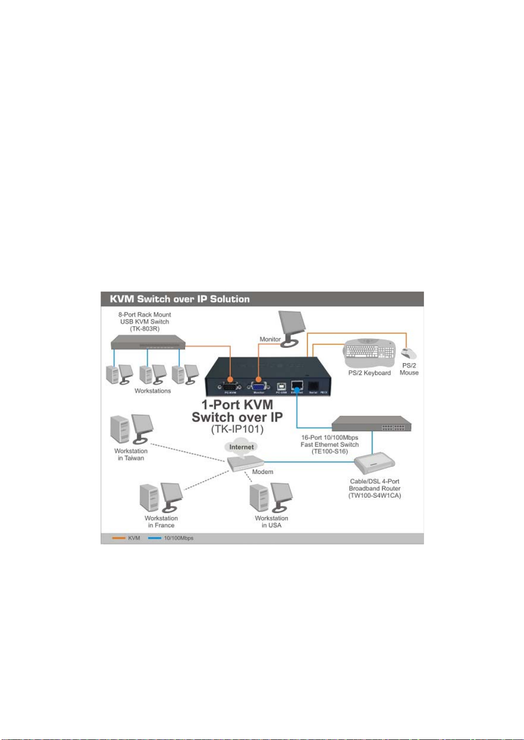
1.2 SYSTEM ARCHITECTURE ............................................................................................................ 6
1.3 TK-IP101 EXTERNAL VIEWS .................................................................................................... 7
TK-IP101 Front View ...................................................................................................................... 7
TK-IP101 Rear View ....................................................................................................................... 8
TK-IP101 Power Socket ................................................................................................................ 8
2 TK-IP101 INTALLATION ................................................................................................................ 9
2.1 PHYSICAL CONNECTIONS .......................................................................................................... 9
2.2 CONFIGURE YOUR SERVERS FOR CONNECTIONS TO TK-IP101 ......................................... 10
2.3 MORE TIPS FOR SERVER DESKTOP CONFIGURATION ........................................................... 12
2.4 CONFIGURE TK-IP101 NETWORK SETTINGS ....................................................................... 14
2.5 CONFIGURE PORT BASE SETTING FOR TK-IP101 ................................................................. 16
2.6 CONFIGURE YOUR FIREWALL/ROUTER FOR ACCESSING TK-IP101 ACROSS INTERNET ..... 18
2.7 INSTALL CERTIFICATES ON TK-IP101 .................................................................................. 19
3 MAKING A VIEWER CONNECTIO N ......................................................................................... 24
3.1 INSTALL WIN32 VIEWER ON THE CLIENT COMPUTER .......................................................... 24
3.2 INSTALL JAVA VIEWER ON THE CLIENT COMPUTER ................................................................ 24
3.3 IMPORT CERTIFICATES TO TK-IP101 VIEWER ON THE CLIENT COMPUTER ......................... 25
Import client certificate to Win32 Viewer ........................................................................... 26
Import the certificates for the Java-based TK-IP101 Viewer ....................................... 26
3.4 SPECIFY THE VIEWER CONNECTION OPTION BEFORE MAKING A CONNECTION ................. 26
ENCODING ............................................................................................................................................... 27
LOCAL CURSOR SHAPE .......................................................................................................................... 27
MISC ........................................................................................................................................................ 27
DISPLAY................................................................................................................................................... 27
3.5 ESTABLISH THE VIEWER CONNECTION .................................................................................... 27
3.6 MOUSE CURSORS SYNCHRONIZATION ................................................................................... 29
3.7 SAVE THE CONNECTION OPTIONS .......................................................................................... 30
3.8 WIN32 VIEWER CHARACTERISTICS ....................................................................................... 30
3.9 TITLE BAR INFORMATION ........................................................................................................ 34
3.10 THE SELECT COMPUTER BOX ................................................................................................... 34
3.11 VIEWER QUICK MENU .............................................................................................................. 36
3.12 JAVA VIEWER CHARACTERISTICS ........................................................................................... 40
3.13 COMMON VIDEO DISPLAY PROBLEM TROUBLESHOOTING .................................................... 40
4 TK-IP101 UNIT MANAGEMENT OVER A SECURE HTTPS BRO WSER CO N N E CTION 44
4.1 WEB-BASED MANAGEMENT INTERFACE ................................................................................. 44
4.2 DOWNLOAD – DOWNLOAD PROGRAMS FOR VIEWERS .......................................................... 46
4.3 VIEWER – VIDEO SERVER NAME & KEYBOARD TYPE SETTINGS ......................................... 47
i
Page 4

TK-IP101 User Guide R1.2
4.4 DATE & TIME – DATE, TIME, GLOBAL TIME ZONE SUPPORT AND NTP SERVER
SYNCHRONIZATION
4.5 VIDEO SERVER – MISCELLANEOUS SETTINGS FOR VIDEO SERVERS .................................. 51
4.6 POWER CONTROL – MISCELLANEOUS SETTINGS FOR VIDEO SERVERS .............................. 53
4.7 COMPUTERS – MISCELLANEOUS SETTINGS FOR VIDEO SERVERS ....................................... 54
4.8 SERVER LOG – LOGGING SERVER EVENTS ............................................................................ 56
4.9 VIDEO MODES – KEEPING, MODIFYING AND AUGMENTING YOUR VIDEO MODE DATA
BASE 57
4.10 ALARMS – E-MAIL NOTIFICATIONS AND SNMP LOGGING SUPPORT .................................. 59
4.11 KVMS – KEEPING AND ADDING YOUR KVM DATA BASE .................................................... 63
4.12 LAN TCP/IP – PORT AND IP SETTINGS ............................................................................... 67
4.13 WAN PPP – PPP SERVER AND CLIENT ................................................................................. 69
4.14 USER STATUS – SHOW THE CURRENTLY CONNECTED USERS ............................................. 73
4.15 USER MANAGEMENT – MANAGE USER ACCOUNTS, RADIUS ACCOUNTING AND REMOTE
AUTHENTICATIONS ................................................................................................................................. 74
4.16 SECURITY – CERTIFICATES INSTALLATION, VIEWER ENCRYPTION AND PASSWORD
POLICIES ................................................................................................................................................. 79
4.17 MAINTENANCE – FLASH IMAGE VERSION INFORMATION, SOFTWARE UPGRADE,
CONFIGURATION BACKUP AND UPLOAD ............................................................................................... 83
4.18 LOGOUT – LOG OUT THE WEB MANAGEMENT ................. ERROR! BOOKMARK NOT DEFINED.
4.19 APPLY SETTINGS – VALIDATE NEW SETTINGS ...................................................................... 87
................................................................................................................................. 49
- -
ii
Page 5

1 INTRODUCTION
The name of TK-IP101 is derived from an acronymic combination from it full
name, 1-Port KVM Switch over IP
powerful machine in itself. Though lightweight in size and compact in form factor,
TK-IP101 is nevertheless a heavy-weight in its functional versatility, rock-solid
robustness and formidable security. It supports full 1024-bit PKI authentication,
256-bit SSL data encryption, LDAP, RADIUS as well Active Directory authenticat
and RADIUS
Dominant yet cost-effective solution for remote server management
scenarios
With the ubiquity of the DSL/Cable technology and the bandwidth availability
therewith, the IP-based KVM technology has emerged as a dominant player in the
new landscape of remote servers management. Today, the IP-based KVM Extender
has been regarded as a better and more cost-effective solution to address the critical
issue of remote servers management, which could only be partially tacTK-IP101d in
the past by expensive yet redundant software solutions or Enterprise Management
System. And TK-IP101 is a robust and versatile solution to address the needs of
modern remote server management scenarios.
Total server control from BIOS level up anytime anywhere
TK-IP101 gives users total control from preboot stage such as the BIOS-level CMOS
setting up to the GUI applications and daily maintenance routines such as power
cycling (power control unit required). And all these could be nicely done on your
admin desk using an ordinary web-browser management interface and a thin-client
software viewer. All you need for accessing your computer is to login the TK-IP101
and download the viewer program and get yourself connected to a whole bunch of
servers in seconds. A truly anytime anywhere access for the server administrator!
Versatile backup connection featuring a PPP Server or PPP Client
To provide the necessary redundancy of a second backup system while your network
might no longer works in critical situation, TK-IP101 also allows an easy and
convenient PPP connection over the dial-in modem phone line. It could serve as a
PPP server to accept a peer computer to make PPP connection request over either a
direct cable connection or a dial-in modem phone line. On the other hand, TK-IP101
could also serve as a PPP client to dial-in to your ISP or enterprise PPP server to
connect to internet, making a truly anytime access for remote client anywhere on
the Internet. Thus, the PPP server/client features in TK-IP101 allow users a second
backup system, which offers a direct cable/modem dial-in access to your connected
servers via PSTN while your network is down.
accounting.
, which well explains the functionality of this
ion
- -
1
Page 6

TK-IP101
Edge of critical Advantage over other remote server management solution
The advantages of using TK-IP101, as compared to the conventional software
remote control solution is that: The hardware-based remote control solution such as
TK-IP101 is able to access the server regardless of the server states while software
remote control solution is non-functional while the server is still in the POST or
preboot stage or in a “blue screen of death”. TK-IP101 also offers power on/off
alternatives if used with a remote power control unit.
Rock-solid stability and ultra-security yet with flexibility and convenience to
use
The TK-IP101 distinguishes itself among its peer products not only in its rock-solid
stability in durable performance, but also in its industry-standard security features
such as full 1024-bit PKI Authentication and 256-bit SSL data encryption. Together
with 3 levels of viewer connection security levels in combination with 3 types of
password policies and three categories of user privileges, all these make TK-IP101 a
ultra-powerful IP Extender machine with ultra-flexibility for a customized balance
between data safety and user convenience. On the other hand, the robustness and
the ease of maintenance of the embedded systems involve zero costs for the unit
management and maintenance.
Global Time Zone and Timer Servers Support
To make TK-IP101 really comfortable with all the global time zones it will be
deployed in, it is vital to provide a convenient Global Time Zone support since it will
give a correct time stamp to all logging events, alert e-mail notifications and won’t
leave server administrators in troubles with calculating the time differences he will
inevitably encounter with servers in different time zones. Additionally, TK-IP101 also
supports NTP time servers and keep its time always sync with the timer servers you
specify. The TK-IP101 is even sophisticated enough to take care of the daylight
saving time in each and every Time Zone/Region, thus saving troubles for updating
time frame with daylight saving specifics every six months.
Upgrade and Configuration Backup is just a breeze
TK-IP-101 is fully Web-enabled to allow software upgrade and configuration
upload/backup over the Web Management Interface. All you need to do is to upload
the files to TK-IP-101 over Web interface and voila it’s freshly restarted and begins
- -
2
Page 7

working with those latest update functionalities and features-all within minutes and
can be performed across oceans-by a remote SUPERADMIN!
Advantages Galore
With TK-IP101, the server administrator can access enterprise server room or data
center on his own seat without toils and troubles of going anywhere from across the
street to oversea. And organizations can enjoy a uniquely centralized and very costeffective control over its dispersed servers in different branch offices, even around
the world, thus saving money for outsourcing costs.
- -
3
Page 8

1.1 Primary features
General features
▪ Full-featured IP-based Remote Control Solution for server management
▪ Provides remote control for several servers when connected to a conventional
KVM Switch
▪ Simultaneous access from multiple users
▪ No user limitation
▪ Facilitate centralized control
▪ Total control over the remote server from BIOS level up to GUI applications
▪ Remote Power On/Off support
▪ Total transparency of control
▪ Ultra-security using full 1024-bit PKI Authentication / 256-bit SSL encryption
▪ Work with LDAP / RADIUS / Active Directory Servers
▪ Ethernet 10/100 and serial PPP connections
TCP/IP remote connection
▪ Web Management Interface for all settings and upgrade/backup features
▪ Support Telnet session and FTP service (disabled by default for more security)
Thin-client Viewer Program
▪ Win-32 viewer and Java viewer for cross-platform compatibility
▪ Connection options configurable for optimized performance
▪ Shared, Non-Shared and View Only sessions
▪ Easy download and installation
▪ Multiple viewer instances can be run on a same client computer
▪ Automatic video optimization
Hi-Speed PPP Connection
▪ PPP Connection support over serial RS-232 interface up to 1 Mbps
▪ PPP server enabling for PPP connection across a pair of modems for secure or
backup direct access
▪ PPP client enabling for PPP connection to the internet with a modem
- -
4
Page 9

Video server
▪ Support up to 1280 x 1024 @ 60 Hz resolution
▪ 8/16-bit color
▪ 3 Video Quality settings
▪ 3 Video Compression schemes
▪ 8-bit color reduction
▪ JPEG Compression option for low bandwidth internet connections
▪ Configurable database to set up new or unknown VGA modes
▪ Virtually compatible to any KVM Switch through simple configuration
Power ON-OFF Control Support
▪ Remote power ON-OFF control over serial interface
▪ Serial commands configurable to fit all serial power control devices
▪ Power ON-OFF privilege only for the SUPERADMIN users
Security
▪ 1024-bit Public key Authentication using certificates generated by an external CA
▪ 256-bit SSL Encryption for keyboard, mouse and video signal transmissions
▪ Remote authentication support for LDAP or RADIUS servers
▪ RADIUS accounting support
▪ 3 SSL security levels :
o No authentication – No encryption
o Server Authentication – SSL encryption
o Server & Client authentication – SSL encryption
▪ 3 password policies :
o No Password
o One global password for all users
o One different password for each user
▪ Linux operating system offers robust virus resistance
Alarms and Notifications
▪ Alert e-mail notification and SNMP trap messages for critical server events such
as No Video, Blue Screen and NumLock Test Failure
User Management
▪ User login either by querying the local user database or by connection to remote
LDAP or RADIUS server
▪ 3 user privileges :
o SUPERADMIN – to access complete set of management features and
o ADMIN – partial set of management and all user features
o USER – only user features
Global Time Zone Support
▪ Time support for all continents and major cities
▪ Time synchronization by connection to any NTP time servers
▪ Automatic Daylight Saving management
user features, including Power ON-OFF remote servers
- -
5
Page 10
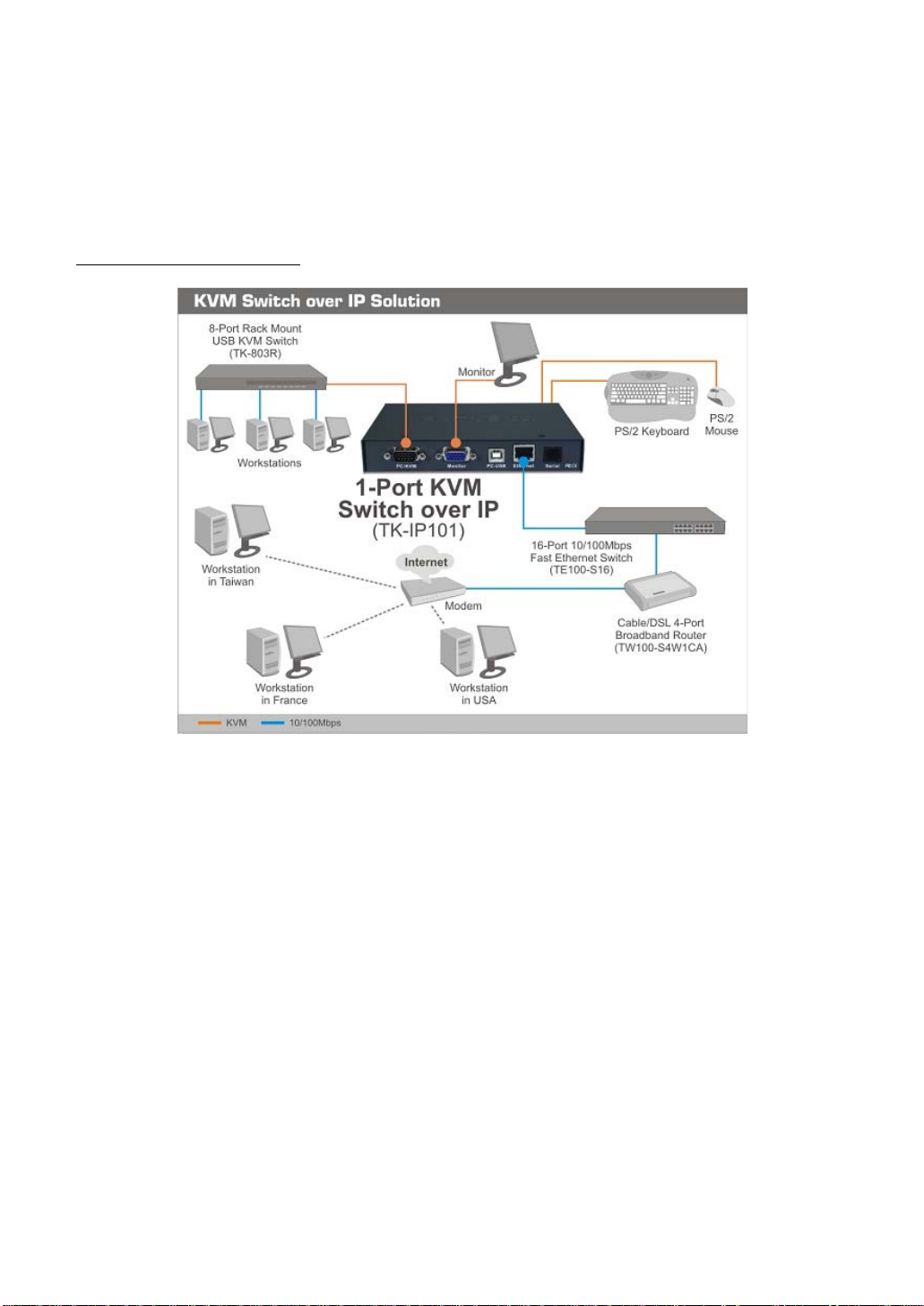
1.2 System Architecture
The TK-IP101 is based on an embedded Linux platform for computing power and
rugged stability. The TK-IP101 employs a High speed Processor to ensure excellent
video quality and fast keyboard / mouse response across the Internet, even when
bandwidth availability is limited.
LAN/WAN Configurations
TK-IP101 connected to a single server
- -
6
Page 11

1.3 TK-IP101 External Views
TK-IP101 Front View
TK-IP101 Front-panel
PS/2 Keyboard port
This is where you connect the PS/2 keyboard for local console.
PS/2 Mouse port
This is where you connect the PS/2 mouse for local console.
Console Management Port (RJ-12)
This is where you connect the serial console cable for advanced console
management of TK-IP101 unit via a serial terminal emulation utility such as
Windows HyperTerminal.
Status LEDs
The 10/100Mbps LED is lit as solid orange when the current digital link is running on
100Mbps speed.
The Link/Act LED gives off solid green light when a network link is established and
flashes whenever network transmission are perceived on the digital port.
The Power LED indicates the Power On status when it is lit as solid green.
The Video LED indicates the normal functioning of video server when it is blinking.
Restore-to-Default Button
The Restore-to-Default button is a tiny recessed button located to the right of the
LED indicators, and can only be accessed by prying down with a pointed needle tip.
To depress the recessed button for over 4 seconds, and upon release, it will restore
TK-IP101 to factory default – the default IP settings and user account settings that
come with factory default settings.
- -
7
Page 12

TK-IP101 Rear View
TK-IP101 Rear Panel
PC/KVM port (HDB-15, integrated with PS/2 Keyboard and mouse signals)
The PC port connector is where you should connect to either a single PS/2 computer
or a single PS/2 KVM Switch, using the 3-in-1 slim KVM cables w/ an integrated
HDB15 connector. However, if you are using USB-enabled computer or USB KVM
Switch, you should additionally use a USB cable to connect to a USB port on your
computer for keyboard/mouse connection.
Monitor Port (HDB-15)
This is where you should plug in the Monitor for your local console on TK-IP101.
USB port (USB Type B)
This USB port provides USB keyboard/mouse connections to a USB-enabled PC, or to
a USB KVM Switch. Thus, if you are connecting any USB-enabled PC or USB KVM
Switch, please use a USB cable to make the connection.
Ethernet Port (RJ-45)
The Ethernet port, or digital port, offers anytime anywhere access of TK-IP101 and
subsequently the conventional KVM Switch(es) and servers/computers connected
behind it to the remote login clients lover LAN/Internet.
Serial Control Port (RJ-12)
The serial control port allows you to connect to either an external modem or a power
control unit or to a cascaded chain of power control units. When added with an
external modem to its serial control port, TK-IP101 could serve either as a PPP
server to allow direct cable connection or dial-in connection from its peer computers,
or as a PPP client to dial-in to the ISP or an enterprise PPP server. Furthermore,
through serial commands sent over its serial control port, TK-IP101 can perform
remote power on/off and power cycling task via the (cascaded) power control
module(s).
TK-IP101 Power Socket
You should use the DC9V 2A Adapter provided within the package. Use of any other
adapter will nullify the warranty.
- -
8
Page 13
2 TK-IP101 INTALLATION
2.1 Physical Connections
Step 1. Power on the TK-IP101: Connect the TK-IP101 Power adapter and power
on TK-IP101.
Step 2. Set up a local console on TK-IP101: If a local console (that is a physical
keyboard, mouse and monitor connected to the TK-IP101) is required, connect the
keyboard and mouse to the TK-IP101 local console ports (that is keyboard, mouse
and monitor port specifically).
Step 3-a. Single Server Mode: If you need to connect to only one
computer/server. Just connect to the PC/KVM port directly to the PC, using the 3-in1 Slim KVM combo cable and/or the USB cable that come with the TK-IP101 packing
box.
TK-IP101 configuration – Single server mode
- -
9
Page 14

Step 3-b. Multiple Server Mode: If you need to connect to multiple
computers/servers, you should use a KVM switch in between the TK-IP101 and your
connected computers/servers. Just connect to the PC/KVM port o the console port of
your KVM switch using the 3-in-1 Slim KVM combo cable and/or the USB cable (if it
is a USB KVM switch) that come with the TK-IP101 packing box. And the KVM switch
will in turn be connected to the multiple computers/servers.
Now that you have set up your local console on TK-IP101, you can now configure
your connected servers just by using the ready access provided by TK-IP101’s local
console.
2.2 Configure Your Servers for Connections to TK-IP101
Mouse acceleration is not supported in TK-IP101. Therefore, you must turn off
mouse acceleration on all your connected servers.
Turn off mouse acceleration & “Snap to” option
Windows XP Platform
Access Control Panel/Mouse. On the Mouse Properties tab, select the Pointer Options
page :
1. Adjust the pointer speed slide bar to the exact middle.
2. Uncheck the Enhance pointer precision option.
3. Uncheck the Automatically move pointer to the default button in a
dialog box
Click OK.
Windows 2000 Platform
Access Control Panel/Mouse. On the Mouse Properties tab, select the Pointer Options
page :
1. Adjust the pointer speed slide bar to the exact middle
2. Select the Acceleration as None
- -
10
Page 15

3. Uncheck the Move pointer to the default button in dialog box
Click OK.
Windows 98
Access Control Panel/Mouse. On the Mouse Properties tab, select the Motion page.
Under the Pointer Speed category:
1. Adjust the pointer speed slide bar to the slowest (leftmost) position.
Click OK.
The mouse setting page on different Windows platforms might be quite different, some gives mouse
acceleration option and some don’t. If you see any mouse acceleration option, please uncheck it. If there is
no mouse acceleration available on the setting page, you can adjust the mouse speed slide bar to either x1 or
the slowest position (such as on Linux platforms). But sometimes, it requires a middle position on the speed
slide bar to make mouse synchronization on the viewer side, for example, Windows XP requires a middle
position on mouse speed. Anyway, the worst case is that you have to make some trial and error to make your
mouse acceleration off and the speed as x 1 (could be at the slowest position or the middle position).
- -
11
Page 16

D D D D
D
D D
D D D
D
D
D D D
D D D
2.3 More Tips for Server Desktop
Configuration
There are several aspects that have to be taken into consideration and maybe
configured on your computers or servers for best performance:
(1) Resolution modes should refrain from too much peculiarity and better
adopt ones that are within TK-IP101’s standard support.
(2) Turn off the Menu special transition effects on your operating system
(especially on Windows XP, if you are using any) such as fade for best
video refreshing effect, especially when you are using Medium or Low
Video Quality as your video filter setting on TK-IP101.
(3) Adjust the server desktop backgrounds as containing preferably plain,
solid colors with simple designs (only for improving video refreshing
speed when bandwidth is critically limited. No need to do so when
bandwidth is ample)
Configure Display Resolution on your Server
TK-IP101 supports most display modes up to 1280 x 1024. However, you might encounter some
display problems when your display card is outputting an unusual display mode. These possible problems
are either no video or abnormal display on viewer screen.
To simplify the display factor before connection to TK-IP101, we suggest you use more standard display
modes such as: 800 x 600 @ 72Hz/75Hz, 1024 x 768 @ 72Hz/75Hz, etc. For the suggested display modes,
please refer to the following table.
640 x 400 640 x 480 800 x 600
56Hz
60Hz
61Hz
64Hz
70Hz
72Hz
74Hz
75Hz
76Hz
78Hz
84Hz
85Hz
100Hz
Note: These are suggested display modes for server desktop connected TK-IP101. However, the actual feasible display
modes for as specific server desktop will be dependent on its display card. Some display modes listed here might not be
feasible with some display card. Try to do some trials to determine the best display mode for your desktop on TKIP101 viewer.
Disable special transition effects on the screen outputs of your connected servers
Go to Control Panel/ Display / Appearance / Effects. And then uncheck the option to disable transition
effects such as Fade for the menus and tool tips. You should perform the same check on each of your
connected servers.
D
D
1024 x
768
D
1152 x
864
1280 x
1024
D
- -
12
Page 17

On Windows platforms such as Windows 98, 2000, XP and 2003 Server, some transition effects might
yield undesirable video refreshing artifacts, especially when you are using Medium or Low Video Quality as
your video filter settings. To avoid undesirable artifacts from appearing on your screen, please turn off the
special transition effects.
Choose plain and solid server desktop backgrounds for your connected servers.
To optimize the bandwidth efficiency and speed up video performance across
bandwidth-limited environment, one should preferably adopt a server desktop which
should be as plain as a color background with a solid and light-colored graphics.
Complex patterns or color gradients should be avoided, if bandwidth is critical in
your application, since they will create more bandwidth demands for their
transmission across internet.
- -
13
Page 18

2.4 Configure TK-IP101 Network Settings
Step 1. Connect your TK-IP101 to the Ethernet LAN.
The factory default network settings for TK-IP101 are as follows:
IP address: 192.168.1.200
Net mask: 255.255.255.0
Gateway: 192.168.1.254
DNS: 192.168.1.254
Step 2. Access TK-IP101 Web Browser Management interface by typing the following
in the address bar of your browser window on a remote client:
https://192.168.1.200:5908
Step 3. Then a login prompt will ask you for the account name the password. Use
the default account and password:
User Name: superuser
Password: superu
After logging in, you will see the TK-IP101 Web Browser Management Interface.
Internet Explorer 7 users, click “Continue to the website (not recommended)”.
Note: Due to added levels of browser security, Internet Explorers 7 users will see red in the
address bar and a “Certificate Error” warning; this is not an issue with the TK-IP101. This
product will continue to function properly. To avoid this event, please refer to this User’s
Guide for instruction on how to configure security setting and creating certificates
Internet Explorer 7.0 Certificate Error message.
- -
14
Page 19

Certificate Error in Internet Explorer 7.0 browser.
Step 4. Go to the LAN TCP/IP page on the TK-IP101 Browser Management Interface
and modify your IP settings. Refer to Section 4.11, LAN TCP/IP – Port and IP
Settings.
Step 5. Apply the new setting by clicking Apply Settin gs.
Step 6. Verify TK-IP101’s network connection.
Connect to TK-IP101 by Web Management Interface using the new IP address.
Note that the IP address should be followed immediately by a colon and the port
base +8 for port number,
https://<IP_address>:<PortBase+8>.
For example, if the IP address is 192.168.1.7 and the port base number is 5900,
then you should enter
- -
15
Page 20

https://192.168.1.7:5908
Remember that it’s a secure SSL encrypted connection, so you should type “https” instead of the usual
“http”. Otherwise, the connection will not be established.
2.5 Configure port base setting for TK-IP101
If you are satisfied with the default port base setting as 5900, you can skip this section.
The default port base for TK-IP101 connection is set at 5900. This means it will use
port 5900 (port base) for viewer connection and port 5908 (port base + 8) for https
web browser connection.
<Port base> – used for viewer connection
<Port base + 8> – used for secure browser connection
However, if you intend to use your own port base setting, just access the Web
Management interface and configure the port base as follows:
For example, if you choose 5970 as your port base, then you have:
5970 – used for viewer connection
5978 – used for secure browser connection
- -
16
Page 21

Click Submit button and Apply Settings button to validate your new setting.
Now you have installed TK-IP101 within your Local Area Network environment, and
can try to establish a remote viewer connection…
- -
17
Page 22

2.6 Configure your firewall/router for
accessing TK-IP101 across internet
To allow access to the TK-IP101 behind corporate firewall/router, please configure
the following settings on your firewall/router (not on your TK-IP101):
Step 1. Configure a virtual server on your router: you should configure (or ask
your net admin to configure for you!) a virtual server as mapped to the TK-IP101
local IP address.
Step 2. Open a port range: (<port_base> ~ <port_base_+_9>) both
inbound and outbound for the virtual server: you should open a port range
according to what you have configured as port base for TK-IP101 previously.
Taking previous example, if we configure TK-IP101 as having a port base of 5970,
then we should open port range 5970~5979 ( that is, <port_base> ~ <port_base
+9>) both for inbound and outbound, in which,
<port_base> = 5970 is the TK-IP101 viewer connection port
. . . . . . . . . . . . . . . . . . . . . . . . . . . . . . . . . . . . . . . . . . . . . .
<port_base + 8> = 5978 is the browser SSL connection port
<port_base + 9> = 5979 is for viewer internal communication, etc.
For example:
Router internet IP ÅÆ virtual server (port range open) ÅÆ TK-IP101 local
IP
61.232.134.120 ÅÆ virtual server (port 5970~5979 open) ÅÆ 192.168.1.7
Once you haved configure a virtual server with appropriate port range open
(<port_base> ~ <port_base_+_9>), you can then try to access your TK-IP101
across internet by using in the public IP address and designated port number. For
example, in this case, we have
Browser access: https://
Viewer access: 61.232.134.120:5970
If you have domain name mapping to the public IP address, you can also use the domain
name, for example:
Browser access: https://
Viewer access: www.mycompany.com:5970
Once you have changed the port base of your TK-IP101, you should also modify the open port range on
your router accordingly, if you want internet access to come across.
61.232.134.120:5978
www.mycompany.com:5978
- -
18
Page 23
2.7 Install Certificates on TK-IP101
You could use the default set of certificates (could be found on CD-ROM) to practice making some
PKI-authenticated connections as long as your network safety is not jeopardized. We advise that it is better to
do the practices within your Local Area Network, which is supposed to be well secured with adequate firewall
and other due precautions against network intrusions. Or if you have already obtained a set of certificates
with the file names and formats required by TK-IP101, you can then use them for TK-IP101 viewer
authentication. However, if you simply use the default set of certificates that comes with TK-IP101, anybody
who has a copy of the default certificates may establish a connection to your servers. . So we strongly
recommend that you obtain your own certificates for TK-IP101 or go forth to generate them using software
like XCA….. For certificate generation using XCA, please refer to
using XCA
First you have to have these certificates ready on your client computers for
uploading to TK-IP101 via a Web browser. If you haven’t obtained your own TKIP101 certificates, you can use the default set of certificates (could be found on the
TK-IP101 support CD-ROM).
Certificates to be installed on TK-IP101:
(1) the root certificate (root.crt)
(2) the server certificate (server.crt), and
(3) the server private key (serverkey.pem)
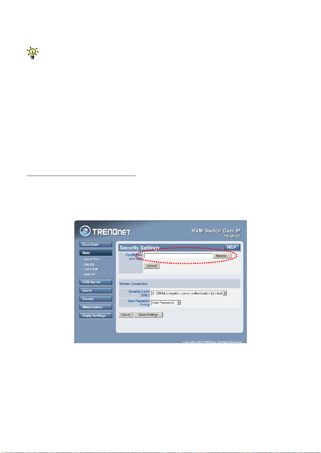
Step 1: Access TK-IP101 Web Management Interface and go to the Security page.
(could be found on the TK-IP101 support CD-ROM).
How to Generate TK-IP101 Certificates
Step 2: Click the Browse Button and use the Choose File dialog box to browse to
your certificate files ….
- -
19
Page 24

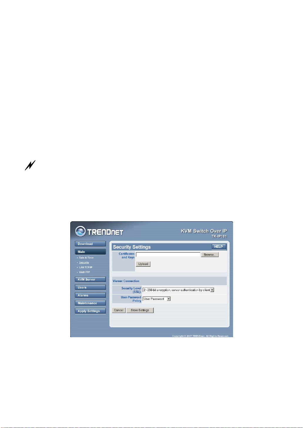
Step 3. Click UPLOAD button to upload the root certificate to TK-IP101. After the
uploading is completed, you can then see the prompt page for reboot.
Click Reboot and wait till TK-IP101 is booted up, then likewise try to import the
server.crt and the serverkey.pem.
You don’t have to reboot each time when you finish uploading one certificate. You could do one
complete reboot at the end when you finish uploading all of them. To return to the previous Security page
for uploading another certificate without going to immediate reboot, you just click the Security page
hyperlink on the left frame of the browser window.
- -
20
Page 25
2.8 Select a Security Level for Viewer
Connection
Step 1. Go to the Security page on the TK-IP101 Web management interface and
select a viewer connection security level.
There are three security levels for choice:
• Level 1: No encryption (No SSL)
• Level 2: 256-bit encryption, no user certificate required for user authentication
• Level 3: 256-bit encryption, user certificate required for authentication (PKI)
Security level 1 offers a non-secured connection, and hence should be used with
caution when TK-IP101 is intended to be accessed through external network. For
level 1, there’s virtually no encryption.
Security Level 2 offers a secured SSL connection that provides encryption for mouse,
keyboard and video but uses no PKI-authentication.
Security Level 3 offers a secured SSL connection that provides encryption for mouse,
keyboard and video, and uses 1024-bit PKI-authentication.
The choice of a security level to be implemented for the TK-IP101 viewer connection is of most
importance, especially when your remote server connections requires a high security that can keep your
servers safe from unauthorized entries and/or network sniffers.
Step 1-a. If you choose to implement PKI authentication feature on TK-IP101
viewer, you have to select Level 3 viewer security connection on the Security page of
your TK-IP101 browser interface.
Then Enter the server password.
Here you should enter the password that has encrypted the server private key in the
server private key file, serverkey.pem. You should enter the correct server password
here in order to make successful viewer connection with TK-IP101 in level 3 security
setting. If you use the standard set of certificates provided on the Support CD ROM
disc, the password that encrypts the server private key is serverpwd
However, if you use your own set of certificates, you should get the correct server
password from the Certificate Authority that issues those certificates.
- -
21
Page 26

Step 2. Go to the Apply Setting page and hit the Apply Setting button to validate
your selection.
2.9 Select a User Password Policy
Step 1. Select a User Password Policy.
TK-IP101 offers three types of password policies On the drop-down combo box, you
can select your password policy for viewer connections:
No Password
Global Password
User Password
No Password – the viewer will prompt you for no password. Anyone who is with the viewer
and passes the security level check of the viewer could well establish the connection.
Global Password
want to make viewer connections to TK-IP101.
User Password
each login user will be checked against his or her corresponding password before allowing
viewer connection.
Global user password
enter the password that is used when the global user password setting is enabled as
your active password policy.
Step 2. Go to the Apply Setting page and hit the Apply Setting button to validate
your selection.
– the viewer will prompt you for a global password, which is used by all who
– the viewer will prompt you with user-specific password. With this setting,
: If you adopt the Global Password Policy. Here you should
There are altogether nine ( 3 x 3) possible combinations of Viewer Security Levels + Password Policies
that are available for a flexibility to adapt to your security needs. The administrator can choose an optimized
combination of user password policy and the SSL / PKI Authentication according to his security/convenience
concern.
SSL / PKI
Authentication
No password
No SSL-No PKI N – N – N G – N – N U – N - N
SSL – No PKI N – S – N G – S – N U – S - N
SSL - PKI N – S – P G – S – P U – S - P
User Password Policy
Global
Password
User-specific
Password
G – Global Password U – User-specific Password
S – 256-bit SSL Encryption
P – 1024-bit PKI Authentication
N – Not available
Please note: Either Password Policy or Security Level (SSL/PKI authentication) settings should be used
with due precaution: If you adopts No Password Policy and No SSL encryption/No SSL authentication,
anyone with a viewer and knowledge of the access IP and port number of TK-IP101 can establish a remote
connection
- -
22
Page 27

Now your TK-IP101 is ready for a PKI-authenticated plus SSL-encrypted viewer
connection! All you have to do is to distribute the followings to you remote connection
client:
1. Certifidcates: (as you have obtained from your CA (Certification Authority).
They are required only if you select level 3 viewer security)
root.crt
client_name.p12. (client_name is freely chosen)
2. Certificate password: (as you have obtained from your CA. It is required
only if you select level 3 viewer security)
clientpwd (if you use the default set of certificate provided on TK-IP101
CD-ROM)
3. User account and password: (as you have specified in the User Management
page. It is required only if you choose User Password Policy)
Superuser / superu
Admin / 123456
User / 123456
(If you use the default user accounts/passwords)
4. Global Password: (as you have specified in the Security Page. It is required
only if you use the Global Password Policy)
(You will be prompted when choosing it as your password policy on the
Security Page.)
- -
23
Page 28
3 MAKING A VIEWER CONNECTION
The TK-IP101 provides a win32 viewer for Windows clients and a Java viewer for
cross-platform on any major operating systems.
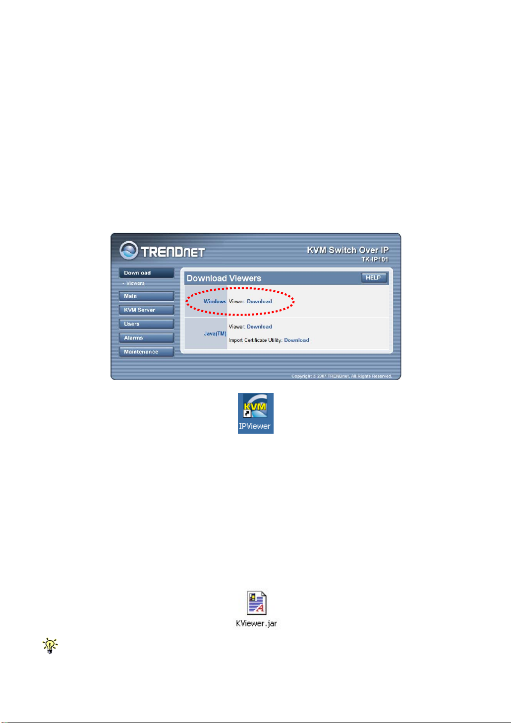
3.1 Install Win32 Viewer on the Client
Computer
Go to the Download page to download the Win32 viewer, winview_install.exe. Install
the viewer program on the client computer that will connect to TK-IP101. After
installation, a desktop icon will be created on your client desktop.
3.2 Install Java Viewer on the client
computer
Before you can use the java viewer, KViewer.jar, on any OS platform, you should
first install the Java Runtime Environment, JRE 1.5.0 or higher, which is
downloadable from http://www.java.com.
To download Java Viewer, just go to the Download page of the Web Management
interface.
After all, to run the small java program, you don’t have to actually save the
disk, since it is small (only 70 KB), you can choose to open it directly wile download is completed.
- -
24
Kviewer.jar
to your local hard
Page 29

On some client platforms such as Linux, after you have installed the JRE on your client platform, you
have to set the path information in order for the client system to know where the Java compiler program is.
3.3 Import certificates to TK-IP101 viewer on
the client computer
If you will be using only the non-PKI authenticated viewer connections to TK-IP101 (such as Level 1
No encryption and No Authentication
–
authentication by client
and proceed to the next.
To make full PKI authenticated viewer connection with TK-IP101, you need to import
client certificates to the Win32 viewer and Java Viewer on the client computer.
The Tk-IP101 is already preinstalled with a default set of certificates. You can use
the default client certificates provided on CD ROM. However, it also allows you to use
your own set of certificates.
Note that if you intend to use your own set of certificates instead of the default set of certificates, you
should not only import the client certificates to the win32 viewer/java viewer on remote client computer, but
you should also import the root certificate, server certificate and the server private key to the TK-IP101. To
import certificates to the TK-IP101, please go to the Security page of the TK-IP101 Web Management to
upload your own set of certificates. For details, please refer to
), you are not obliged to use or import any certificates. If so you can skip this section
Viewer Encryption and Password Policies
Generally, the naming requirements of these certificates are as follows:
[Certificates and private key for TK-IP101 to authenticate viewer user logins]
root.crt - TK-IP101 root certificate, mandatory file name
server.crt - TK-IP101 server certificate, mandatory file name
serverkey.pem – TK-IP101 server private key, mandatory file name
[Certificates for remote login users with viewer connections]
client_name1.p12 - client certificate, client name could vary
client_name2.p12 - client certificate, client name could vary
. . . . . . . . . . . . . . . . . . . . . . . . . . . . .
Specifically, we should import client certificate(s) in .p12 format, to the win32 viewer
and Java Viewer on your client computer, using each of their own certificate import
utilities.
, and Level 2 –
.
256-bit SSL encryption and only server
Section 4.15, Security – Certificate Installation,
- -
25
Page 30
First, you have to have your certificates ready, either on a removable media or you
can copy them to your local disk on the client computer.
Note that if you copy certificates to your local hard disk, you might need to delete them from your local
hard disk after finishing importation, so that others won’t have access to your certificate files. Although the
personal client certificate (that is, the
blame!
Note that the win32 viewer and the java viewer require separate certificate
importation utility to get the job done.
client_name1.p12
) is password-protected, more caution is never to
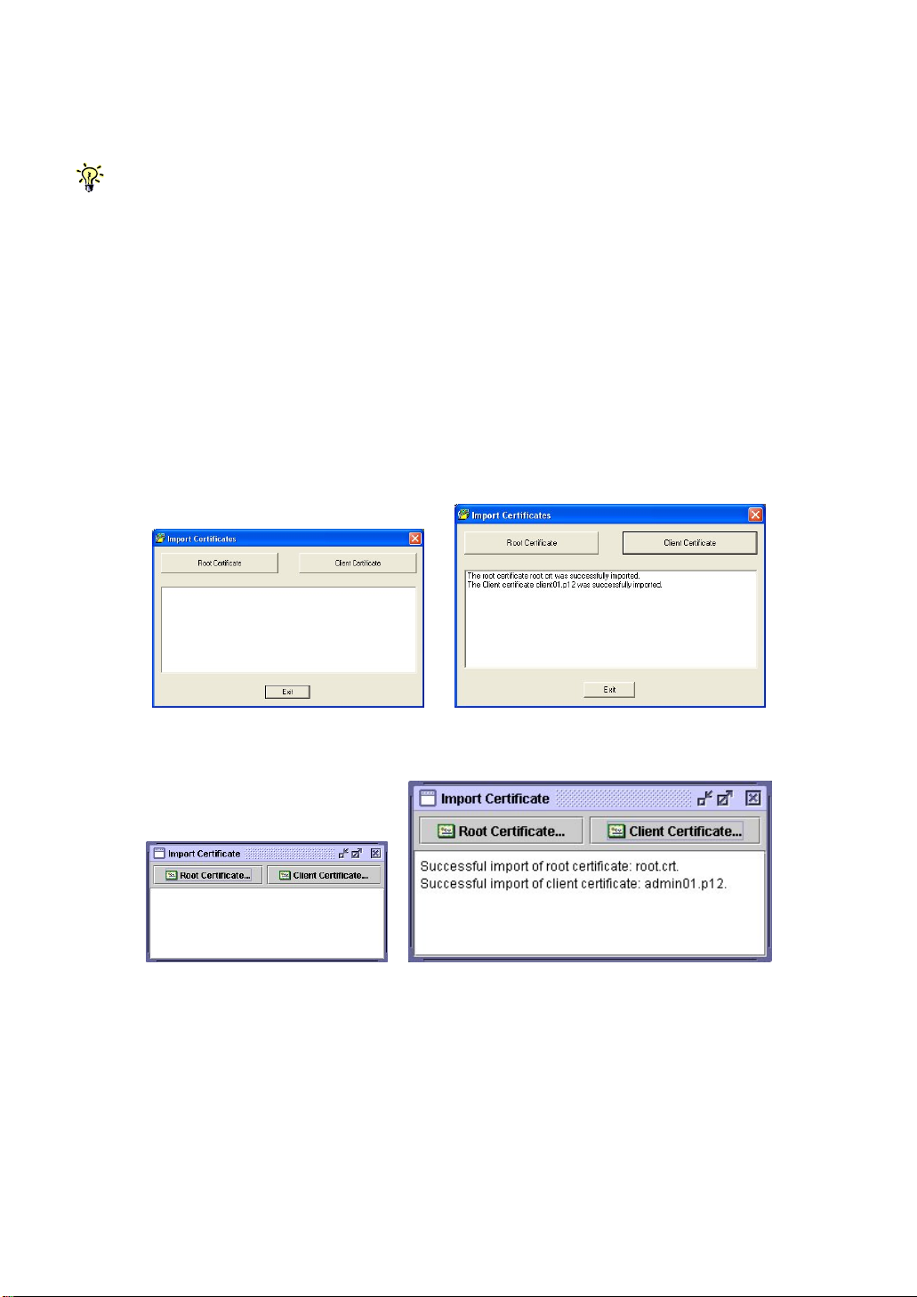
Import client certificate to Win32 Viewer
Run the importation utility by accessing Start/Programs/Trendnet /IP Viewer/Import
Certificates. Click Root Certificate to import root certificate and then click Client
Certificate to import client certificate.
Import the certificates for the Java-based TK-IP101 Viewer
Now you have imported certificates to the viewers on the client computer
and are now ready for making a viewer connection of any security level
setting ….
3.4 Specify the Viewer Connection Option
before Making a Connection
The viewer connection option interface provides you with several alternative options
to use in combination for optimization of your viewer connection.
- -
26
Page 31

Connection details box
Click the Options button on the Connection Details dialog box.
Win32 Viewer Java Viewer
Setting connection options
Encoding
Internet: Video quality is optimized for viewer connection across internet
LAN: High Video Quality for viewer connection over LAN
Raw: Best Video Quality with no compression
Local Cursor Shape
No cursor: local cursor invisible on IP Viewer.
Dot: dot shape for local cursor on IP Viewer.
Normal: arrow shape for local cursor on IP Viewer.
Misc
Shared Session: multiple users access same server desktop
View Only (inputs ignored): Keyboard and mouse inputs are ignored (not
restricting keyboard and mouse access on other users).
Display
Restrict pixels to 8-bit (for slow networks): color reduction to 256 colors for slow
connection
Allow JPEG compression (Best compression, lower quality): JPEG compression for
slow connection.
Scale x/y (server/viewer): Scale the display output on viewer (not affecting the
actual transmission bandwidth)
3.5 Establish the viewer connection
- -
27
Page 32

Using Win32 IP Viewer for Connection
First, run the viewer program, enter the access IP and port number for TK-IP101.
Default IP address: 192.168.1.200
Login dialog box (Win32 Viewer)
At the password or private path phrase prompt, just enter the user name and
password as required:
Default user & specific password:
User: superuser
Password: superu
Or, if you are using the Global Password policy setting …
Default global password: 123456
Or, if you are using the Level 3 security setting that requires installation of
certificates for PKI authentication (For details, please refer to section 3.3, Import
certificates to IP Viewer on the client Computer, and Section 4.15, Security –
Certificates Installation, Viewer Encryption and Password Policies.)
Default private path phrase: clientpwd
After you have entered either the global password, user name and password, or
private path phrase as its security and password policy require, a viewer connection
will be established successfully.
Some Tips about Viewer Connection
If you want to specify the type of your viewer connection rather than using the default one, you can click
the
Options
button and optimize your connection parameters. Please refer to previous section for details.
- -
28
Page 33

Note that you can simply type in the access IP of TK-IP101 server without specifying
its port number only when the port number is default to 5900
IP_address [only if port number is default to 5900]
192.168.1.200
Of course, you can always type
IP_address:port_number
192.168.1.200:5900
However, if the port setting on TK-IP101 is already changed to other port number,
you have to specify its specific port number following the IP address. For example, if
you want to connect to port 5910 on the TK-IP101 server, type, for example:
192.168.1.8:5910
To configure the port base number, please refer to
Section, 4.11., LAN TCP/IP – Port and IP Settings
.
Connection Performance Tuning
However, if you are using a dial-up modem line and experiencing slow keyboard
mouse movement and response, you might check whether you are using the default
LAN encoding scheme or even the RAW scheme, which requires much more packet
quantity in transmitting a video frame; or there is a network bottleneck somewhere
in between TK-IP101 and your client desktop. For more details, please refer to
Section 3.13, Common Video Display Problem Troubleshooting.
3.6 Mouse Cursors Synchronization
Normally, you will see both the local cursor and the remote cursor on the view area.
You can specify the shape of the local cursor as seen within the Viewer Window
either as a dot, an arrow or none (not showing any local cursor within the viewer
area). Also if these two cursors become out of sync, all you need to do is to hit
default the mouse synchronization hotkey (right) Ctrl – (right) Ctrl – Home to
synchronize the two cursors.
- -
29
Page 34

Note that, while operating your mouse, it is not necessary to wait till the remote cursor has actually caught
up with the local one before you can click on the target in the view area. Actually, you can click the target just
using the local cursor well before your remote cursor catches up the target!
Mouse cursors out of sync Mouse cursors in Sync
Local/remote cursor resynchronization hotkey- RCtrl-RCtrl-Home
3.7 Save the Connection Options
After you have optimized you connection options, you might want to save the
connection options. Next time when you log in with the IP viewer to TK-IP101 server,
the viewer on that specific client computer will use the stored connection parameters
as well as the password (but not the private path phrase, which is not saved since it
is used by secured/PKI-authenticated connection) for connection with TK-IP101.
To save connection options, click the KVM icon on the Viewer title bar to call forth
the Viewer Quick Menu and select Save the connection options.
IP Viewer Quick Menu (Win32 viewer)
3.8 Win32 Viewer Characteristics
Adjust the Window Size
- -
30
Page 35

Viewer Window with scroll bars (Win32 viewer)
The size of the IP viewer window can be adjusted by dragging the border of the
viewer windows.
Change the Viewer size to full screen mode
Note that only the win32 viewer supports full screen mode. The java viewer does not support full screen
mode.
Click the IP viewer icon on the title bar of the viewer window to evoke the Quick
Menu. Select the Full Screen option on the Quick Menu
A message box will appear to remind you how to exit the full screen mode:
Full screen prompt – Ctrl – Esc to return to normal mode
Click OK, and the viewer goes to full screen mode.
- -
31
Page 36

To exit the full-screen mode, just hit Ctrl-Esc to bring up the local task bar. Rightclick the viewer taskbar icon to bring up Quick Menu, then click to deselect the full
screen mode to restore it to window mode.
Scale the Window Size of your viewer
Click the IP viewer icon on the title bar of the viewer window to evoke the Quick
Menu. Select Connection options on the Quick Menu
Scale the viewer window to ½ size
On the Connection Options dialog box, specify the preferred proportions of the
viewer window, for example: ½, and then check the option. Click OK to scale the
window to half size.
- -
32
Page 37

Centralize your remote server control
If you have multiple TK-IP101 units installed in a distributed manner among your
global branch offices, you can then simultaneously monitor different remote servers
distributed over this TK-IP101 infrastructure on a single client desktop.
Five Win32 viewers on a Windows client desktop
(each showing one different remote server desktop)
Four Java Viewers on a Linux client desktop
(each showing one different remote server desktop)
- -
33
Page 38

3.9 Title Bar Information
ServerRoom_TPE: This is the name you specified for your Video Server.
Window XP Professional: This is the name you specified for this connected computer
53 ms: This is the capture time that is used for capturing the video image
Shared: This is a shared session that allows other authorized user logins
OPTIMISING: This indicates that the KVM video server is optimizing the video capture from
the server desktop.
Not shared: This indicates a non-shared session that blocks others from subsequent logins
No Encryption: This indicates no encryption for signal transmission (Level 1)
256-bit encryption: The current viewer session is using 256-bit SSL connection (Level 2 and 3)
PKI Authentication: The current viewer session is PKI-authenticated (Level 3)
Connection Information shown on the Title
3.10 The Select Computer box
Win32 Viewer
The Select Computer box allows the user to perform intuitive Click-and-Switch
operation without memorizing the varying port-switching hotkey commands of all
kinds of KVM Switches possibly installed behind TK-IP101. However, to use the
click-and-switch feature provided by it, you must first configure the KVM switching
hotkey commands for that KVM Switch model via the Web Management Interface .
Please refer to Section 4.10, KVMs – Keeping and adding your KVM Data Base
The Select Computer box shows always on top of your screen once the IP Viewer
connection is successfully made. On the box, you can see the computer icons
together with the computer names you have already specified for each of them using
the web management interface.
Click-and-Switch
To switch to a computer, just click a computer icon on the box.
Note that those computer icons represents only the computer names you have
already registered using TK-IP101 Web management interface, not indicating any
status of its connection such as whether it is in powered-on or powered-off state.
- -
34
Page 39

Java viewer
To bring up the Select Computer Box, click the Viewer Computer List option on the
Quick Menu. For the java viewer, the Select Computer Box will not appear by default.
Quick Menu (Java Viewer)
To switch to specific computer, just click any item on the listing …
Select Computer Box (Java Viewer)
- -
35
Page 40

3.11 Viewer Quick Menu
The Quick Menu of TK-IP101’s Win32 Viewer can be evoked by clicking the
program icon on the left most of the title bar, or right-clicking anywhere on the title
bar.
For the Java Viewer, Just click the Menu options under the Title Bar to evoke the
Quick Menu.
- -
36
Page 41

Select computer
Select the remote computer by a drop-down combo box
View Computer ICONs
Open the Select Computer box for computer selection by clicking icons
- -
37
Page 42

Select Computer Box (Win32 viewer)
Adjust Screen
Fine-tune the screen area by pixel shifts.
Adjust Screen Box (Win32 viewer)
Connection options
Open the Connection Options dialog box
Connection Options dialog Box (Win32 viewer)
Connection info
Show the Connection information of the viewer session.
- -
38
Page 43

Connection Info (Win32 viewer)
New connection
Make another new connection by the viewer.
Save connection options
Save the connection options settings such as those connection parameters specified
within the Connection Options Box and also the password within the registry of the
client computer.
By selecting this option, you can save your session password as well as other
connection parameters in the registry of your client computer, so that next time
when you log in the viewer for a new session, you will not be prompted for session
password again. However the client path phrase required in the connection of Level
3 security (256-bit SSL encryption and PKI Authentication) will not be saved and will
be asked for every time when you login under Level 3 security setting.
Screen Refresh
Force updating of the viewer screen output
Full Screen
Change the viewer screen to Full Screen mode (Only the Win32 Viewer supports this
Full Screen option).
Send Ctrl-Alt-Del
Send a Log On (Log Off) key sequence to the remote end.
Scanning
Start scanning through computers by issuing a programmable port switching
commands with a delay time to a conventional KVM Switch behind TK-IP101.
Computer Power Off
Send a Power Off serial port command to the remote power control unit (Only
SUPERADMIN or ADMIN is allowed).
Computer Power On
Send a Power On serial port command to the remote power unit (Only SUPERADMIN
or ADMIN is allowed)
- -
39
Page 44

Power-on/off options grayed-out (unavailable for User privilege)
Now you have got yourself well familiar with IP viewer interface, so go ahead to use
and enjoy the remote viewer connection!
3.12 Java Viewer Characteristics
You can perform likewise operations (except full screen) on java viewer. Although
the java viewer has slightly different menu arrangement, you should find it as easy
to operate on as the win32 viewer interface.
3.13 Common Video Display Problem
Troubleshooting
IP video server supports most major display modes up to 1280 x 1024. However,
some display problems will occurs, when either there is abnormal or unusual display
output from your server or the display resolution is over the biggest support of 1280
x 1024, or the display vertical frequency is beyond the support range in that pixel
dimension.
To yield best video results on the viewer screen display on remote login client, you
should also refer to Section 2.2, Prepare your Computers for Connections to TK-
IP101, and Section, 2.3, More Tips for Server Desktop Configuration for more details
about how to prepare your servers/computers before getting them connected to your
TK-IP101.
The followings are some common video display problems and their troubleshooting….
Q. There seems to be many artifacts or residuals not getting refreshed on the viewer
screen. Is there any way to improve the video display quality on viewer screen?
A: The causes of these artifacts or residuals could be:
- -
40
Page 45

(1) The video filter currently active on TK-IP101 is either set at Medium Quality or Low
Quality Level. These two video filter levels are for faster response than the High
Quality Level as to increase the response speed over limited bandwidth condition. If
your bandwidth allows or you need higher video quality instead of higher speed, just
change the video filter from Low to Medium or even to High to increase the video
display quality on viewer screen on the remote login client. To raise the Video Filter
Level, please go to the Video Server Page in TK-IP101 Web Management Interface,
and select the filter as either Medium or High Quality according to your requirements.
Note that High Quality video filter gives high quality always on the expense of video
response speed on the viewer screen.
(2) The transitional effect of Windows XP is enabled. The transition effects of menu will
cause refreshing problems in Low/Medium Video Filter settings. Thus, if you are using
a Low/Medium Quality Level of video filter, either try to raise the video filter level to
High Quality (at the expense of response speed) or just turn off the transitional effects
of Windows XP. To turn off the transitional effects of menu on Windows XP, please
refer to Section 2.2, Prepare your Computers for Connections to TK-IP101
Also note that TK-IP101 local console is not affected at all by the Video Filter settings or
by the transitional effects on Windows XP.
Q. The TK-IP101 booting time has become unduly longer over several minutes.
What’s wrong?
A. Please make sure that the external authentication, PPP server/client, time server as well as
power control settings are correct. If you don’t use all these features or the
authentication/time servers are not available, just try to disable them to save booting time
since if you don’t have all these servers present, the TK-IP101 will try to look for them till
timeout. That will waste TK-IP101 booting time considerably.
Q: Video response seems slower in limited bandwidth condition, are there ways to
increase the response speed?
A: There are several ways to increase the response speed on the viewer screen:
(1) Under bandwidth limited condition, you should select a more economical encoding
scheme such as Internet Encoding scheme instead of the LAN or RAW encoding
scheme from the viewer connection option menu. However, if the connection is
made only within LAN with plenty connection bandwidth, LAN or RAW encoding
scheme should be quicker than Internet scheme – since your client computer
won’t have to dissipate extra computing power for decoding the more-compressed
internet scheme.
(2) Use 8-bit color reduction (with only 256 colors instead of the 65K colors in 16-bit
settings)
(3) Use JPEG compression (for best video quality with optimized packet quantities)
(4) Additionally, you could always select either Medium Quality/Low Quality level for
more speed as your Video Filter setting in the Video Server Page of the TK-IP101
Web Management Interface. You could also do something to increase the response
speed: use a server desktop of small resolution (such as 800 x 600) and use a
solid plain color background for server desktop.
Finally, you should check also the networking environment to find if there is some
bottleneck that can be improved or eliminated for more bandwidth throughput.
Q. When connection is first made, the display on the viewer screen seems not
centered correctly and there is black margin on the edge of the viewer screen. How
could I eliminate the black strip?
A. The black strip is the offset that will be seen when the display on viewer screen is not
centered corrected. Probably you have not enabled automatic centering option on TK-IP101,
so please check the followings:
(1) Go to the Video Server page on TK-IP101 Web Management Interface to check
whether the Automatic Screen Alignment option is enabled. If it is not yet enabled,
- -
41
Page 46

please check the option, click Submit button and then go to Apply Settings page to
click the Apply Settings button to restart Tk-IP101 with new setting.
(2) When the viewer connection is made, select the Adjust Screen option on Viewer’s
Quick Menu, and the Adjust Screen dialog box appears. On it, check whether you have
Automatic Centering enabled. If it is not yet enabled, please check this option to
enable it. If it is already checked, please uncheck it and then wait for at least 15
seconds and then check the option again to force the video server to align (center)
the display in the viewer screen.
Q: I can log in and make successful browser connection with TK-IP101. However, I
cannot make a valid viewer connection or the TK-IP101 does not respond to my
viewer connection request. What can I do about it?
A: The TK-IP101 video server might not function properly. First, make sure your account have
the SUPERADMIN privilege. If not, you should request one that has the SUPERADMIN
privilege to do the troubleshooting job for you. Next, go to the Apply Settings Page on the
Web Management Interface and then hit the Apply Settings button to restart TK-IP101. Then
wait for at least 10 more seconds for it to start completely. Try to make the viewer connection
again to see if it is back to normal. Second, If the Apply settings button could not bring back
the IP video server to normal working condition, try to hit the Emergency Reboot button
(could be found on the Maintenance Page of the Web Management Interface) for a complete
start from ground level. An Emergency Reboot is a clean reboot, and it takes longer time for
TK-IP101 system and video server to load, thus you have to wait at least a minute for the
- -
42
Page 47

system to be up and running. Then try to make the viewer connection again to see if it is
brought back to normal function again. A cold boot of TK-IP101 is always a last resort to bring
the TK-IP101 back – just try to disconnect the power adapter form TK-IP101 and wait for
sometime (30 seconds) before plugging in again for a cold start over.
- -
43
Page 48

4 TK-IP101 UNIT MANAGEMENT
OVER A SECURE HTTPS BROWSER
CONNECTION
TK-IP101’s Web Management interface uses only password authentication to
authenticate login user’s identity. After user identity is authenticated (that is, if you
have typed in the right user name with a right password in the login prompt…), an
SSL-secured browser connection using 256-bit cipher strength is established.
4.1 Web-based Management Interface
Type in the correct IP address and port number:
https://<IP_address>:<port_number>
` https://61.222.144.195:5908
Remember that it’s a secure SSL encrypted connection, so you should type “https” instead of the usual
“http”. Otherwise, the connection will not be established. The port number might vary according to its setting
on the TK-IP101 server. By default, the browser connection uses port 5908. Both the user name and
password are case-sensitive.
Three User Privileges – SUPERADMIN, ADMIN, USER
TK-IP101 offers three categories of user privileges for Web Management:
SUPERADMIN, ADMIN and USER.
SUPERADMIN – Full access to Web Management features [and Power ON-OFF feature on viewer]
ADMIN - Partial access to Web Management features [and Power ON-OFF feature on viewer]
USER – Only minimal access to Web Management features (only the Download and the Logout
pages)
- -
44
Page 49

Full access - SUPERADMIN Partial access - ADMIN Minimal Access (User privilege)
TK-IP101 Browser Management Access Privilege
Feature Page SUPERADMIN ADMIN USER
√
Download
Viewers
Date & Time
Video Server
Power Control
Computers
Server Log
Video Modes
Alarms
KVMs
LAN TCP/IP
WAN PPP
User Status
User Manag.
Security
Maintenance
Logout
Apply Settings
√
√
√
√
√
√
√
√
√
√
√
× ×
√
× ×
√
× ×
√
× ×
√
× ×
√
× ×
√
√
√
×
√
×
√
×
√
×
√
×
√
×
√
×
√
×
√
×
√
√
√
√
×
- -
45
Page 50

4.2 Download – Download Programs for Viewers
TK-IP101 Viewer Download Page
The win32 viewer program supports all the current Windows platforms such as
Windows 98/Me/NT/2000/XP/2003 Server, and the java viewer is truly crossplatform for all major Operating Systems including Windows, Linux, MacOS, etc.
However, you should install Java Runtime Environment specific for your TK-IP101
client platform before using the Java Viewer. To get the Java Runtime Environment,
please download from the Java website: http://www.java.com
.
- -
46
Page 51

4.2 Viewer – Video Server Name & Keyboard Type Settings
After any setting change, click the
Apply Setting
click
to apply new settings to TK-IP101 immediately.
Submit
button to save new setting to the TK-IP101 database, and then
Viewer Related Settings
Server Name for Viewers
Enter the server name you choose and it will appear on the title bar of your TK-
IP101 Viewer window.
Keyboard Layout
Choose the keyboard layout for TK-IP101 according to the real keyboard you’ll be
using on the remote login client. Choosing the correct keyboard layout for your
keyboard is very important since some keycodes are represented by different key
locations in different keyboard layout. And keyboard layout setting ensure you will
have a matching keycode output as you have on the physical keyboard on client
computer. The default keyboard layout is the US keyboard (US).
- -
47
Page 52

Largest Possible Screen
Select the largest workable resolution for your display device.
640 x 400
640 x 480
800 x 600
1024 x 768
1152 x 864
1280 x 1024
TK-IP101 supports up to 1280 x 1024 pixels for resolution.
Hot keys
The Hot Keys as here specified are the key sequence that precedes the command
string and they are to be directed not to your local client PC, nor to your remote
server, but to TK-IP101 itself. The hot keys here are default to CTLR – CTLR, that is,
two consecutive Right Control keys (Please note that this is the right control key
(CTLR), NOT the left control key, CTRL). And the Mouse-Resynchronize
Hotkey is default to Home key (HOME). For example, to synchronize the remote and
the local mouse cursor, you have to hit CTLR – CTLR – Home. (To find out the key
positions on a standard keyboard, please click the Keyboard drawing
detailed key mapping.)
Of course, you can also customize the mouse resynchronization hotkey for your own
preference.
hyperlink for a
If you are using MacOS as your TK-IP101 client for connection, you might find that the default mouse
resync hotkey – CTLR-CTLR-Home - does not work on Java viewer running on your MacOS. That is
because the Right Control key on Mac keyboard sends out different keycode as the PC keyboard. If that is
the case, you might consider to configure your mouse resync hotkey as, for example, CTLL- CTLL – S, so
that you could sync mouse cursors from your Macintosh computer or notebook.
- -
48
Page 53

4.3 Date & Time – Date, Time, Global Time
Zone Support and NTP server
synchronization
After any setting change, click the
Apply Setting
click
to apply new settings to TK-IP101 immediately.
Submit
button to save new setting to the TK-IP101 database, and then
Current Date and Time
Enter the correct date and time here and click Set Current Date and Time button to
set current system time on TK-IP101.
Note that if you check the option to
time setting will be periodically synchronized to the time of NTP server specified on each restart of the TK-
IP101 and every hour.
Automatically Synchronize with an Internet Time Server (NTP)
, the
- -
49
Page 54

Time Zone
Select the Time Zone / Region and City or Town from the available list as seen in the
drop down combo boxes. For example: you can choose Australia as your Time
zone and Melbourne as your region.
Select the Region Zone
Select the Time Zone / Region.
Select the Town for the Selected Region
Specify a Town in the selected Time Zone / Region to be the place you install TKIP101 and synchronize its system time accordingly.
Internet Time
The option here is for the automatic synchronization of TK-IP101 time with a Time
Server on the Internet. You can check the option and then specify the time servers
you prefer. TK-IP101 will try to synchronize with the timer servers every time it
starts or restarts and will continue to synchronize every hour thereafter.
The Primary NTP server is the server TK-IP101 will first try to synchronize with, and
the secondary NTP server is the backup time server that TK-IP101 will synchronize
with when the first time server is not available.
Automatic synchronize with a Time Server (NTP)
Synchronize TK-IP101 system with time server you specify. Note that if you choose
this option the original Current Date and Time settings you manually entered will be
refreshed with the time provided by the internet time server.
Primary time server
Enter the domain name of the time server you choose as your primary time server.
The default one is time.stdtime.gov.tw
Secondary time server
Enter the domain name of the time server you choose as your secondary time server.
The default one is tick.stdtime.gov.tw
There are many internet time servers available. You can search in the Internet for ones that are nearer
to the location you install TK-IP101. Note that you should choose your internet time servers based on the
principle that a time server nearer to you will reduce time latency in time synchronization.
- -
50
Page 55

4.4 Video Server – Miscellaneous Settings
for Video Servers
After any setting change, click the
Apply Setting
click
to apply new settings to TK-IP101 immediately.
Submit
button to save new setting to the TK-IP101 database, and then
Default Settings
Filter
Specify the Video Filter Level for the TK-IP101 video server.
Based on the bandwidth availability, you can select one of the three modes of video fileter levels:
High Quality, Low Video
Medium Quality, Low Speed
Low Quality, High Speed
Each of the three video filter levels is adapted to different combination of video quality and bandwidth
requirements. Users can select their preference according to actual video quality preference and network
bandwidth availability. However, there’s always a trade off between video quality and response speed when
under limited network bandwidth availability.
High Quality, Low Speed
condition such as LAN or broadband internet. With this setting, the viewer screen will be updated on
minimum amount of video change. This setting will require more bandwidth than the other two filter levels
and video refresh speed will be slower (however, only noticeable when bandwidth is very limited). This filter
provides the best image quality.
(Light Filter): - This level is recommended for ample bandwidth networking
- -
51
Page 56

Medium Quality, Medium Speed (Medium Filter): This level is recommended for internet connection to
connect to TK-IP101 half a world away across internet with not so ample bandwidth like in LAN for a
smooth video performance. This setting may require more bandwidth than the High Speed, Low Video
Quality option. This is most often the best speed / bandwidth compromise.
Low Quality, High Speed
such as a dial-up modem line to the Internet) With this setting, TK-IP101 viewer screen will be updated on
maximum amount of video change. Strong filter requires less video bandwidth, hence can offer high speed
for keyboard/mouse/video response.
Automatic Screen Alignment
This option is to center the view screen automatically to eliminate the offsets
sometimes seen in the viewer screen as black gaps.
Automatic Image Optimization for Speed
This option is to optimize the screen frame images TK-IP101 captures for more
display.
(Strong Filter): This level is recommended for very limited bandwidth condition,
Attached KVM
KVM Model
Select the model of the conventional KVM Switch to be attached to the backpanel of
TK-IP101. Note that you can also add specific models to the available list so that
your computer icon could support the port switching hotkeys of any specific KVM
model upon clicking.
Number of Computers
Specify a maximum number of total connected PCs for the KVM Switch behind TKIP101. You can specify a maximum of 256 computers, as you might have a cascaded
configuration of several cascaded KVM Switch units behind TK-IP101.
Scanning
Scanning Period
Specify the scanning duration for each connected PC, if no KVM (Keyboard - Video Mouse) event happens to interrupt the scanning.
Scanning Delay
Specify the delay time that TK-IP101 will wait after it last perceives a KVM event
before it switches to the next connected PC.
Performing the NumLock Test while scanning
Check this option if you want to perform autoscanning, TK-IP101 will send an alert
e-mail or SNMP message to the designated e-mail address if the NumLock test fails.
While scanning, TK-IP101 will also send a NumLock signal to the PC. If the PC returns a response,
then he NumLock LED will be lit. The NumLock test can serve as a test to see if the connected PC is still
responsive to keyboard event. And also the NumLock signal will serve as a “wake up” signal if the PC is in
sleep mode.
- -
52
Page 57

4.5 Power Control – Miscellaneous Settings
for Video Servers
After any setting change, click the
Apply Setting
click
to apply new settings to TK-IP101 immediately.
Submit
button to save new setting to the TK-IP101 database, and then
Power Control
Enable the power control via the serial port
the remote power control over TK-IP101 viewer interface.
Power Control device initialization-dialog (chat script style)
your power control device. However, if your power control device does not require a
login script, just leave blank the field for login script.
For the individual setting of the serial ASCII port commands that should be sent for Power ON / OFF
of each port, you should go to
Computers
page for configuration.
: Check this option if you want to enable
: Specify a login script for
- -
53
Page 58

4.6 Computers – Miscellaneous Settings for
Video Servers
After any setting change, click the
Apply Setting
click
to apply new settings to TK-IP101 immediately.
Submit
button to save new setting to the TK-IP101 database, and then
Select the KVM Port Number
computer is connected. You can just select from the drop down combo box for the
target port number to be designated with various port specific settings on this page,
such as computer name, the scanning and alarm options, power-on and power-off
commands.
You can use the drop-down combo box or use the Previous and the Next button to
select KVM port for setting.
Computer Name
Enter a character string (32 characters max)
this case, it is Redhat Linux) for the computer you will connect to that specific port
(in this case, it is port 6) on the conventional KVM Switch behind TK-IP101. A
Maximum length of 32 characters for each name is allowed. The computer names
you specify here for each port will appear all together in the Select Computer Box
when logging in IP Viewer.
Computer Scanning and Alarms
Do not include in scanning process
is port 6) to be included in TK-IP101 auto-scanning, you should check this option to
exclude it.
Do not generate alarm
or SNMP messages for this computer then you should check this option to exclude it.
: Select the target KVM port to which your target
: Designate the computer name (in
: If you do not want any KVM port (in this case, it
: If you do not want the scanning process to generate alarm
- -
54
Page 59

Power Management
Power Down Command
control port for the additional remote power control unit you connect to the serial
control port of TK-IP101, e.g. “/F016\” to power down power bank 01 port 6 with
the cascadable power control module such as the TK-RP08; “/F000\” to power off all
ports on all bank. To send the power down command to a specific port over the
viewer, just switch to that port and evoke the viewer Quick Menu to click Power off
Delay (sec.)
and that of the power on command, when the Restart Computer option is enabled
and TK-IP101 receiving a specified alarm (either No Video, Blue Screen, NumLock
Test failure). For more details, please refer to the Section 4.9, Alarms – e-mail
Notifications and SNMP Logging Support for Server Alerting Events. The delay time
between the power off and the power on command is default to 5 seconds.
Power On Command
port for the additional remote power control unit you connect to the serial control
port on the backpanel of TK-IP101,, e.g. “/O016\” to power on power bank 01 port
6 with the cascadable power control module such as the ioPower; “/O000\” to power
on all ports on all bank. To send the power on command to a specific port over the
viewer, just switch to that port and evoke the viewer Quick Menu to click Power on
: Specify the delay time between the sending of power down commands
: Specifies the power down command sent over the serial
: specifies the power on command sent over the serial control
When using a remote power control device for power control of your connected server, please note that
some newer motherboard form factors, such as ATX, etc, will require BIOS option adjustment to respond to
the resumed power feed from its power bus by your power control device. Usually, you should enable the
Power Loss Restart
so that your connected servers can boot up when your power control device is feeding power to its power bus.
option on your Motherboard BIOS (or similar option depending on your BIOS vendor),
- -
55
Page 60

4.7 Server Log – Logging Server Events
After any setting change, click the
Apply Setting
click
to apply new settings to TK-IP101 immediately.
Submit
button to save new setting to the TK-IP101 database, and then
Each log item in the server log file records a specific server event and is preceded by
the date and time it is written and then followed by the description for that specific
log event.
Enable
Print Statistics
activity by TK-IP101 remote users, you should check this option to print statistics to
the server log file.
Refresh
newer server log events may have happened and being logged after your previous
access of this server log page, you need to click the Refresh button to read newer
log events.
Clear
Emergency Reboot
: Check this option enable the logging of TK-IP101 server events.
: To record the statistics of the video server and port switching
: Click the Refresh button to refresh the screen output of the log file. Since
: Click the Clear button to empty the log file contents.
Note that server log will also be erased after you perform a complete reboot remotely by hitting the
button in the Maintenance page or when TK-IP101 suffers a power loss.
- -
56
Page 61

4.8 Video Modes – Keeping, Modifying and
Augmenting your Video Mode Data Base
After any setting change, click the
Apply Setting
click
to apply new settings to TK-IP101 immediately.
Submit
button to save new setting to the TK-IP101 database, and then
Select a Video Mode
mode database. Each video mode is indicated by the pixel dimension (length by
width) at a certain vertical refresh frequency:
Width_in_pixels x Height_in_pixels @ Refresh_Rate_in_Hz
For example, 1024 x 768@60Hz is a video mode and 1024 X 768@72 Hz is another
video mode.
: Select a video mode already built in within TK-IP101’s video
Video Setting
To modify or add a new display mode involves special technical details. For ordinary
users, we do not recommend you to modify the existing video mode database.
Incorrect modification of an existing video mode might cause improper display of
that video mode on the viewer screen.
To modify an existing video mode, just select one existing video mode from the
list and then modify the parameters therein, and then click Save button to save the
new settings for the video mode.
To add a new video mode, just enter a new video mode in the Select a Video
Mode field, and then enter all the parameters here below:
Refresh rate
Screen Width
: Refresh rate of the target video mode.
: Screen width of the target video mode.
- -
57
Page 62

Total Width: specifies the total screen width of the target video mode.
Hsync Start
Screen Height
Total Height
Vsync start
To change these parameters, you should follow VESA standard specifications in order for the video
: specifies where the horizontal synchronization should start.
: specifies the screen height of the target video mode.
: specifies the total screen height of the target video mode.
: specifies where the vertical synchronization should start.
capture function of TK-IP101 to work properly.
Write New Settings
Just click the Submit button to write new setting to your video mode database.
Suppress the selected video mode
To eliminate the target video mode from the video mode database, click the
Suppress button. Normally, one does not have to suppress a screen definition.
Restore previous settings
To undo the previous one addition or elimination of a video mode, just click the
Restore button. Note that you can only undo previous one move.
The following diagram explains about the all these parameters in geometric relations
to a formation of a video mode….
Total
Hsync
Start
Screen
Total
Height
Vsync
Start
Screen
Height
DISPLAYED AREA
- -
58
Page 63

4.9 Alarms – e-mail Notifications and SNMP
Logging Support
After any setting change, click the
Apply Setting
click
This Alarms feature should be used in conjunction with TK-IP101’s auto-scanning function, thus TK-
IP101 can serve as a non-stop server health-monitoring agent.
This page pertains to the alarm event notification. TK-IP101 is capable of sending
immediate e-mail alerts as well as SNMP trap messages (SNMP logging) when there
is blue screen, no video, or NumLock test failure from a remote computer.
When TK-IP101’s scanning function is enabled, it scans through the connected
computers, and when detecting any outbreaks of critical server events, it will trigger
e-mail notifications as well as SNMP logging.
to apply new settings to TK-IP101 immediately.
Submit
button to save new setting to the TK-IP101 database, and then
\
Log SMTP
Email from
sender on the alert mails, for example: PM@Trendnet.net
Email to
support@Trendnet.net
Copy to
contact@Trendnet.net
SMTP server
(mail server) that will help TK-IP101 to send out e-mail alerts to its recipients. We
have the SMTP server name here as, for example, smtp.wanadoo.fr.
: Enter the e-mail address for TK-IP101 that will appear as the e-mail
: Enter the recipient e-mail address(es), for example:
: Enter the e-mail address(es) for the c.c. list, for example:
: Here you enter the server name or IP address of the SMTP server
- -
59
Page 64

Use comma to separate multiple e-mail entries, for example:
Email to: support@Trendnet.net, emma@international.com, joe@netview.co.jp
Copy to: charles@unisum.com.tw, daniel@runfast.com, coco@TK-IP101pro.com.au
Log SNMP
TK-IP101 supports SNMP traps so that it can provides the alarms information to the
SNMP manager devices on the network.
Primary Manager
: Specify the IP address of the Primary SNMP manager device on
your network.
Secondary Manger
: Specify the IP address of the Secondary SNMP manager device
on your network.
SNMP Community
: Specify the name of the SNMP Community to which your SNMP
Management host and SNMP agent should belong.
Note that the SNMP manager devices and agents should belong to an SNMP community, which is a
collection of hosts grouped together for administrative purposes.
There are three types of alarm triggering events TK-IP101 can respond to: No
video, Blue Screen and NumLock test failure. According to the settings you have
specified, these alarm triggering events can be configured to trigger TK-IP101’s
immediate responses, such as restart the computer, alert emails or SNMP trap
messages.
No Video Alarm (Power-Off or Out-of-Range Video)
No Video could be a result from power failure or an out-of-range video mode. If you
want TK-IP101 to respond immediately to this alarm event, just check the Enable
Alarm option.
Note that you first have to check the
option could be enabled. If the
Email
send an e-mail even if these two options are selected!
Blue Screen Alarm (Text mode)
Blue screen is a result of Operating System fatal error. If you want TK-IP101 to
respond immediately to this alarm event, just check the Enable Alarm option.
Since the output of a blue screen is sometimes identical with a text mode screen in terms of its
resolution being 600 x 400 or 600 x 480. Therefore, TK-IP101 will regard a text mode output either of 600
x 400 or 600 x 480 as identical to a blue screen, and send out alert e-mails or SNMP trap messages according
to its configuration.
NumLock Test Alarm (Frozen Keyboard)
Enable Alarm
Enable
Alarm option is left unchecked, it won’t restart computer or
option before the
Restart Computer
and
Send an
- -
60
Page 65

The NumLock test is to send a NumLock signal to the computer, and the computer
normally should return a response immediately so that the NumLock LED indicator
on the keyboard will be lit to indicate the success of the test.
The failure of a NumLock test indicates at least a keyboard failure to respond to this
NumLock signal, or it might be due to bigger problem such as system failure, or
simply a powered-off state.
Enable Alarm
: Check this option to enable TK-IP101 to respond to specific alarm
triggering events.
Restart Computer
: Check this option to restart computer upon specific alarm
triggering events.
Send an e-mail
: Check this option to send an alert e-mail upon specific alarm
triggering events.
Send an SNMP Trap
: Check this option to send an SNMP trap message upon specific
alarm triggering events.
If you uncheck the
Restart Computer
the
Enable Alarm
and
Send an E-mail
option, you won’t trigger any alarm types even if you have checked
option.
For the MIB structure of TK-IP101, please refer to the followings: (you can also find it in the form of a
TK-IP101-MIB.txt
file,
, on the TK-IP101 Support CD-ROM).
TK-IP101-MIB DEFINITIONS ::= BEGIN
IMPORTS
enterprises
FROM RFC1155-SMI
OBJECT-TYPE
FROM RFC-1212
TRAP-TYPE
FROM RFC-1215
DisplayString
FROM RFC1213-MIB;
prosum OBJECT IDENTIFIER ::= { enterprises 997 }
products OBJECT IDENTIFIER ::= { prosum 5 }
kvmIP OBJECT IDENTIFIER ::= { products 4 }
TK-IP101 OBJECT IDENTIFIER ::= { kvmIP 1 } -- trap numbers can be under
here
trapInfo OBJECT IDENTIFIER ::= { TK-IP101 1 } -- typical root for the trap
variables
-- TK-IP101 Object
alertMessage OBJECT-TYPE
SYNTAX DisplayString (SIZE (0..256))
ACCESS read-only
STATUS deprecated
DESCRIPTION
"The text of the alert message."
::= { trapInfo 1 }
TK-IP101Name OBJECT-TYPE
SYNTAX DisplayString (SIZE (0..256))
ACCESS read-only
STATUS deprecated
DESCRIPTION
- -
61
Page 66

"The Name of the TK-IP101 unit that generated the trap."
::= { trapInfo 2 }
computerNumber OBJECT-TYPE
SYNTAX INTEGER (1..65535)
ACCESS read-only
STATUS deprecated
DESCRIPTION
"the number of the computer that originated the trap."
::= { trapInfo 3 }
computerName OBJECT-TYPE
SYNTAX DisplayString (SIZE (0..256))
ACCESS read-only
STATUS deprecated
DESCRIPTION
"The Name of the computer that originated the trap."
::= { trapInfo 4 }
videoMode OBJECT-TYPE
SYNTAX DisplayString (SIZE (0..256))
ACCESS read-only
STATUS deprecated
DESCRIPTION
"The blue screen video resolution."
::= { trapInfo 5 }
-- TK-IP101 Traps
noVideo TRAP-TYPE
ENTERPRISE TK-IP101
VARIABLES {
alertMessage,
TK-IP101Name,
computerNumber,
computerName,
}
DESCRIPTION "No Video (Power-Off or Out-of-Range Video) Alert "
::= 1
blueScreen TRAP-TYPE
ENTERPRISE TK-IP101
VARIABLES {
alertMessage,
TK-IP101Name,
computerNumber,
computerName,
videoMode
}
DESCRIPTION "Blue Screen (text mode) Alert "
::= 2
numockTest TRAP-TYPE
ENTERPRISE TK-IP101
VARIABLES {
alertMessage,
TK-IP101Name,
computerNumber,
computerName,
videoMode
}
DESCRIPTION "Numlock Test(Frozen keyboard) Alert "
::= 3
END
- -
62
Page 67

4.10 KVMs – Keeping and Adding your
KVM Data Base
After any setting change, click the
Apply Setting
click
to apply new settings to TK-IP101 immediately.
Submit
button to save new setting to the TK-IP101 database, and then
Select a KVM Model
Select a KVM Switch definition from the drop-down combo box for modification. The
KVM Switch definition you select will appear in the Model Name field just below.
KVM Model Setting
Model Name
input field where you can enter a new KVM Switch model name and later adding it to
the KVM Switch database.
Number of ports
model.
Note that some models can be daisy-chained together to expand the total port capacity. If you intend to
add a KVM switch model to the database and use it as in daisy-chained configuration with other KVM
switches, you should here specify its maximum port capacity as expandable in this configuration. TK-IP101
allows a maximum setting of up to 256 ports.
Escape Hot key Sequence
that precedes the command string, together to be directed, not toward TK-IP101,
but toward the conventional KVM Switch connected to TK-IP101’s PC port. There are
: This input field shows the KVM model of your selection. It is also the
: Specify the maximum port capacity of the selected KVM Switch
: The Escape Hot Key Sequence here is the key sequence
- -
63
Page 68

up to a maximum of 4 keys that can be specified for the Escape hot Key sequence.
The Escape Hot Key sequence setting allows you to use the port switching hotkeys
offered by the conventional KVM switch behind TK-IP101.
Normally the Escape hotkey sequence uses only two consecutive strokes. The Escape hotkey sequence
is vendor-specific and will vary according to different KVM switch manufacturers. Before you are adding a
new KVM switch definition to the database, it is useful to know the Escape hotkey sequence for the target
KVM Switch. In this case, we have the Escape Hotkey Sequence as two consecutive Scroll Lock keys.
Delay between keys (ms)
: Specifies the delay time in milliseconds (from 10 to 1000
milliseconds) that TK-IP101 should wait before sending out the next key in the
sequence for port switching hotkeys.
Normally, you will have no need to adjust the delay for any KVM Switch definition already there in the
existing database, unless you experience some problem or irregularity in port switching due to improper
delay time. However, if you intend to add a new KVM definition to the existing database and the default
delay time is not appropriate for use, you then might need to adjust the delay time for optimal performance.
To obtain the optimal delay time, you have to make a few trial port switching with different delay time
settings to determine an optimal value.
Also note: It is possible to insert a precisely programmed delay between two keys if you need to increase
the common delay value selected above. To do so, just type d (xxx), xxx being the value in milliseconds up to
1000. For example, d (50) makes a 50 millisecond extra delay. For details, please refer to the following
passage.
KVM key Sequence for Port Selection (Sent after hotkey
) : Here you can edit the
port selection command strings, one separate line for each port. For example, in the
previous figure we have the typical settings of a non-cascadable 8-port KVM Switch.
The Escape Hot Key Sequence, together with what you have specified here in the
editable area for the KVM Key Sequence for Port Selection, will jointly make up the
port switching sequence that will be sent out when you click the icons within the
Select computer Box. For example: in the editable area you have …
1 Æ send out Scrolllock – Scrolllock – 1 as port switching sequence when clicking 1
Computex Box…..
2 Æ send out Scrolllock – Scrolllock – 2 as port switching sequence when clicking 2
Computex Box…..
st
icon on the Select
st
icon on the Select
…………………………………………………………………………………….
8 Æ send out Scrolllock – Scrolllock – 8 as port switching sequence when clicking 8
Computex Box…..
th
icon on the Select
- -
64
Page 69

However, some other command string you will see in the editable area might seem
as complex as 0 1 0 1 d(1000) ESC.
For example: in the editable area now you have …
0 1 0 1 d(1000) ESC Æ send out ScrollLock–ScrollLock–0-1-0-1, then delay 1000 milliseconds and then
send out an Escape key as port switching sequence when clicking 1
0 1 0 2 d(1000) ESC Æ send out ScrollLock–ScrollLock–0-1-0-2, then delay 1000 milliseconds and then
send out an Escape key as port switching sequence when clicking 2
st
icon on the Select Computex Box…..
nd
icon on the Select Computex Box…..
…………………………………………………………………………………….
0 1 0 8 d(1000) ESC Æ send out ScrollLock–ScrollLock–0-1-0-8, then delay 1000 milliseconds and then
send out an Escape key as port switching sequence when clicking 8
th
icon on the Select Computex Box…..
The hotkey sequence , 0 1 0 1 ESC, means switching to bank 01 port 01 and then
revoke the OSD menu by an ESC key. Note that you should have at least one white
- -
65
Page 70

space between keycode entries. Also you should enter one line of command string
per port. To select a port, TK-IP101 generates first the Escape hot key sequence
selected above, followed by the port sequence into the line corresponding to the port
number. Thus, together with the preceding hotkey sequence, ScrLk – ScrLk, this will
make up a complete hotkey command for port selection.
To specify the key sequence in this editable text area, you have to enter the keycodes. Note that the
keycode for a specific key might not exactly correspond to what you have seen on that physical key. Instead,
you should reference the “keyboard drawing” diagram that can be accessed via the hyperlink on the right side.
Also reference the CAUTION warning on the bottom right of this page.
Figure 4-1 Standard Keyboard Mapping Diagram
Save the (new) KVM Model Settings
the database.
Suppress this KVM model
If you want to suppress the target KVM Switch definition, you can then click the
Suppress button to eliminate it from the existing database.
:
: Click the Save button to save new settings into
- -
66
Page 71

4.11 LAN TCP/IP – Port and IP settings
After any setting change, click the
Apply Setting
click
to apply new settings to TK-IP101 immediately.
Submit
button to save new setting to the TK-IP101 database, and then
TCP/IP Settings
TCP Port base : Specify the port base for viewer connection with the TK-IP101
server. You can choose any available port setting starting form the lowest port base
alternative of 5900 with an increment of 10 right up to port 6090. The port base you
choose is exactly the port number that TK-IP101 uses for viewer connection and
“port base + 8” is the exact port number used by secure http connection of the
browser connection. After you have made the port base modification, remember to
hit the Submit button, and then hit the Apply Setting button (found on the Apply
Settings page) to reboot TK-IP101.
Host Name : Specify the host name for TK-IP101 as appears within your Local Area
Network.
Domain Name (Leave empty if unknown)
IP101 host.
IP Address
network.
Network Mask
Gateway
Primary DNS Server
setting for the e-mail alerts function in TK-IP101.
: Enter a fixed IP address that will be used by TK-IP101 in your local area
: Enter the correct subnet mask for your local network.
: Enter the correct IP for your gateway.
: Enter the primary DNS Server for TK-IP101. This is a required
: Specify the domain name for your TK-
- -
67
Page 72

If you are hosting multiple TK-IP101 units within your networking environment and you want to allow
external internet access to these multiple TK-IP101 units by using only an external IP together with a set of
dedicated port numbers each for a different TK-IP101 unit ….. then, one usual practice is to configure a set
of virtual servers on your router so as to map each
port number
allow remote clients to login multiple TK-IP101 units only by using different port number mappings.
that is assigned to a specific TK-IP101 unit. Thus, you need only one external IP address to
external access_IP: port_number
pair to an
internal IP:
Use DHCP :
Normally, it is NOT recommended to use the DHCP setting for TK-IP101. However, if you have no
choice but to use DHCP as the only available source for TK-IP101 local IP, you can still have the choice to
check the option to enable it.
This option allows you to configure TK-IP101 as a DHCP client using the IP address
assigned by a DHCP server.
- -
68
Page 73

4.12 WAN PPP – PPP Server and Client
After any setting change, click the
Apply Setting
click
to apply new settings to TK-IP101 immediately.
Submit
button to save new setting to the TK-IP101 database, and then
TK-IP101 can either serves as a PPP server for the peer computer to dial-in for
connection, or as a PPP client to dial in a PPP server to connect to a network or the
Internet. The PPP connection serves as a backup connection mode when direct
network connection is not available or just broken down. With TK-IP101’s high
speed serial control interface, it could offer excellent bandwidth to PPP connection
either when TK-IP101 is connected as PPP server or PPP client.
PPP Connection
Disabled PPP
The default setting of this PPP connection option is default to Disable PPP.
If you have direct network connection, normally you don’t have to choose PPP
connection as your connection mode. Thus, the Disable PPP option is the default
setting. However, if direct network connection is not available, you could choose to
enable TK-IP101 in PPP server mode or PPP client mode according to the real
connection scenarios.
:
- -
69
Page 74

Enable TK-IP101 PPP Server for connection request from a peer computer
Enable PPP Server
server, which could accept a peer computer’s PPP connection request either over a
direct serial cable connection, or via a dial-in modem connection.
: Check this option if you want to enable TK-IP101 as a PPP
PPP Connection over direct serial cable with TK-IP101 as PPP Server
To enable TK-IP101 as the PPP server, you should still specify the following
settings ….
TK-IP101 IP address
used by the TK-IP101 in the PPP connection. This IP address here entered will be
used only in PPP connection by TK-IP101 alone, and should be distinct from the IP
address (default = 192.168.1.200) that is specified in the LAN TCP/IP page and used
for connection via direct network.
Peer IP Address
assigned by TK-IP101 to the peer computer that has requested a PPP connection to
TK-IP101 PPP server.
User Name
peer computer.
: Here you should specify the user name for PPP connection login by the
: Enter an IP address here (default = 192.168.2.200) to be
: Enter another IP address here (default = 192.168.2.201) to be
- -
70
Page 75

Password : Here you should specify the password that is used by peer computer.
Confirm password
Modem Initialization (Chat Script Style)
script that will initialize modem to be ready for connection. The standard script
provided here by default should be able to work on most of the PPP connection over
direct serial cable (Null Modem):
TIMEOUT 3600
CLIENT CLIENTSERVER\c
PPP Connection TK-IP101 Local IP address : When the PPP connection is established,
the TK-IP101 local IP address that is used for PPP connection will be shown here, for
example: 192.168.2.200. However, if the PPP connection is not yet established, the
IP address will be shown as Unknown. Note that this IP address is used for TK-IP101
PPP server, and is distinct from the one (default = 192.168.1.200) that is used by
TK-IP101 on local area network.
Enable TK-IP101 PPP Client for Dial-in connection to a PPP server in your
ISP or to an Enterprise PPP Server
You could enable the PPP Client feature, if the only way to get your TK-IP101 on
network is through TK-IP101’s dial-in request to your ISP or enterprise PPP server.
In most cases, you should request a fixed IP address for TK-IP101 as a PPP client,
so that remote users who will access TK-IP101 will know how to access its correct
IP. If, however, the a static IP is not available, as in some cases using a dial-in
account given by ISP, you could always look up the dynamic IP assigned to TK-
IP101 by your ISP or enterprise PPP server and give it to those remote users who
will want to access TK-IP101 in this way.
: Here type in the same password again for confirmation.
: the modem initialization script is a chat
First, you should have an Dial-in account from your ISP or enterprise RAS service that accept PPP
connection over phoneline.
Enable PPP Client : Check this option if you want to enable TK-IP101 as a PPP client,
which could dial in via a phone modem to your ISP or Enterprise PPP server.
User Name
client to log in to the ISP or enterprise PPP server.
Password
logging in to the PPP server.
Confirm password
: Here you should specify the user name used by TK-IP101 as a PPP
: Here you should specify the password that is used by TK-IP101 for
: Here type in the same password again for confirmation.
- -
71
Page 76

Modem Initialization (Chat Script Style)
: the modem initialization script is a chat
script that will initialize modem to be ready for connection. The standard script
provided here by default should be able to work on most of the modem:
'ABORT' 'BUSY'
'ABORT' 'ERROR'
'ABORT' 'NO CARRIER'
'ABORT' 'Invalid Login'
'ABORT' 'Login incorrect'
'' 'AT&F'
'OK' 'AT%C3\\N3&K3B0N1'
'OK' 'ATD0860922000'
'CONNECT'
PPP Connection TK-IP101 Local IP address : When the PPP connection is established,
the TK-IP101 local IP address that is used for PPP connection will be shown here, for
example: 62.147.111.39. However, if the PPP connection is not yet established, the
IP address will be shown as Unknown. Note that this IP address is used for TK-IP101
PPP client, and in most cases, is assigned by the PPP server and thus is distinct from
the one (default = 192.168.1.200) that is used by TK-IP101 on local area network.
- -
72
Page 77

4.13 User Status – Show the Currently
Connected Users
Connected Users
In this field, one can click the Refresh button below and see the currently connected
users who are now having viewer connections with TK-IP101.
Note that: Only when you have selected your password policy to be User Password policy, will the
currently connected users be registered and shown on this page. If you are using other password policies such
as No Password or Global Password, you will not have any connected users shown on this page, since when
adopting Global Password / No Password policies, you have already implied that the distinction of the user
identities is not necessary.
:
- -
73
Page 78

4.14 User Management – Manage User
Accounts, Radius Accounting and Remote
Authentications
After any setting change, click the
Apply Setting
click
to apply new settings to TK-IP101 immediately.
Submit
button to save new setting to the TK-IP101 database, and then
User Authentication
: To edit an existing user account, select a user from the list and then press the
Edit
Edit button. A Use Edit page appears with the selected user’s User ID (User Name)
and User description on it.
Make necessary editing and enter the user password and confirm it again, or maybe
modify the access privilege as is necessary, then click Save button.
After clicking the Save button, a box appears to remind you that the Save action will
overwrite an existing user account, and you should be aware of it. If the modification
is just what you want, just click OK, and then click the Save button again to confirm
your new modifications on that existing user account.
- -
74
Page 79

If you decide to abandon editing an existing user account, you can always click
Cancel to abort and return to the User Management page.
: To add a new user account, just press the New button. A default User page
New
pops up for you to enter the User ID, User Description, Password. After you have
completed, click Save to exit. If you decide to abandon the setting, you can always
click Cancel to abort and return to the User Management page.
Delete
then press the Delete button to delete it immediately form the user list.
RADIUS Accounting
Normally, RADIUS accounting is disabled by default. However, if you have RADIUS
accounting enabled on a RADIUS server or LDAP server, you can check the option of
RADIUS Accounting and subsequently configure its relevant settings to take
advantage of this feature.
: To delete a user account from the data base, just select it from the list and
- -
75
Page 80

Enable RADIUS Accounting
: Check this option, if you want to enable RADIUS
accounting support on TK-IP101.
Accounting Server
: Here you should enter the IP address of the server that offers
RADIUS accounting service.
: Here you should specify the port that is used for Radius accounting. By default,
Port
it is set to 1813.
Secondary Accounting Server (if any)
: Here you should enter the IP address of the
secondary server, if you’ve got any backup RADIUS accounting server that offers
RADIUS accounting service.
RADIUS secret
: Here you should specify the RADIUS secret, or Shared Secret,
between the RADIUS client (i.e. TK-IP101) and the RADIUS server. Note that the
RADIUS secret, or the Shared Secret, is a shared text string that is used as a
password between the RADIUS client and RADIUS server.
Remote Authentication
By default, the Remote Authentication is configured at None – All remote
authentications are disabled. In this case, the authentication is all done locally using
the database on TK-IP101 only. However, if you have remote authentication
supports – such as a RADIUS server or LDAP server – available on your network
environment, You can then always have the choice to enable remote authentication
on TK-IP101, either using RADIUS or LDAP authentication.
Enable Remote Authentication
: You can select either None / LDAP / RADIUS support
from the drop down combo box.
None – Disable the Remote Authentication Support
LDAP – Enable LDAP Authentication
RADIUS – Enable the RADIUS Authentication
- -
76
Page 81

To enable the LDAP Authentication …….
Enable Remote Authentication
method, and then configure subsequent settings:
SSL Access
authentication. However, to use this option, you should make sure your LDAP server
support SSL and also you have to install a distinct set of certificates – ldapcert.crt
and ldapkey.pem – onto the TK-IP101 by uploading them through the Security page
(for details, please refer to Section 4.15, Security – Certificates Installation, Viewer
Encryption and Password Policies).
Server
: Enter here the port number used in LDAP authentication. By default, it is set
Port
to port 389.
Second Server (if any)
enter its IP address here.
User Base Search DN
typical to the LDAP server you use for authentication. By default, the User Base
Search DN is:
However, you should enter your own appropriate one. If you don’t know, you should
contact your LDAP server administrator.
To enable the RADIUS Authentication……
: Check this option if you want to enable SSL access of the LDAP
: Enter here the IP address of the LDAP server.
: If there is a second LDAP server for authentication, you can
: Here you should enter the User Base Search DN, which is
cn=users,dc=abc,dc=TK-IP101,dc=com
: Just select LDAP as the Remote Authentication
- -
77
Page 82

Enable Remote Authentication
method, and then configure subsequent settings:
Server
Port
set to port 1813.
Second Server (if any)
can enter its IP address here.
Password Authentication Protocol
authentication protocol to be either CHAP or PAP.
RADIUS secret
between the RADIUS client (i.e. TK-IP101) and the RADIUS server. Note that the
RADIUS secret, or the Shared Secret, is a shared text string that is used as a
password between the RADIUS client and RADIUS server.
: Enter here the IP address of the RADIUS server.
: Enter here the port number used in RADIUS authentication. By default, it is
: If there is a second RADIUS server for authentication, you
: Here you should specify the RADIUS secret, or Shared Secret,
: Just select RADIUS as the Remote Authentication
: Here you should select the password
- -
78
Page 83

4.15 Security – Certificates Installation,
Viewer Encryption and Password Policies
After any setting change, click the
Apply Setting
click
to apply new settings to TK-IP101 immediately.
Submit
button to save new setting to the TK-IP101 database, and then
Certificate and Keys (root.crt, server.crt. serverkey.pem, ldapcert.crt,
ldapkey.pem)
File path
you are going to install into TK-IP101. You don’t have to actually type in the path
yourself, just hit the Browse button, and use the Choose File dialog box to browse to
your certificate files ….
: Here you can specify the file path that is directed toward the certificates
- -
79
Page 84

Then click UPLOAD button to upload your certificates, one at a time, to TK-IP101,
and the certificate will begin uploading to TK-IP101. After the uploading is
completed, you can then see the prompt page for reboot.
PKI Authentication for Level 3 security setting
You have to upload a set of certificates into TK-IP101:
root.crt
server.crt
serverkey.pem
SSL Access for LDAP Authentication Authentications
ldapcert.crt
ldapkey.pem
- -
80
Page 85

For details, refer to Section 4.14, User Management – Mange User Accounts, Radius
Accounting and Remote Authentications.
You don’t have to reboot each time when you finish uploading one certificates. You could do one
complete reboot at the end when you finish uploading all of them. To return to the previous Security page
for uploading another certificate just click its hyperlink on the left frame of the browser window.
Viewer Security Connection Level
:
TK-IP101 offers three levels of security for viewer connection. On the drop-down
combo box, you can just choose either one of the three viewer security levels as
appropriate to your real demands on viewer connection security:
Level 1 uses No SSL data encryption and No authentication. This is the most straightforward
setting that opens most convenience if there are no security concerns at all. Anyone who have
a viewer and internet connection could easily connect to TK-IP101 as long as the user passes
the policy requests.
Level 2 uses SSL encryption for viewer connection, but only requires server-side
authentication by viewer client. That is, remote users who want to make viewer connections
are not require to install certificates on their client computers. However, the viewer connection
is encrypted with 256-bit SSL technology to ensure any data contents transmitted via the
viewer connection is protected, including keyboard, mouse and video signals.
Level 3 uses 256-bit encryption as well a bi-directional PKI authentication between TK-IP101
server and viewer client. With this level of setting, all remote users who want to make viewer
connection at all, should require installation of a proper client certificate, which is signed by
the same private key of the CA that issues the root.crt and server.crt of TK-IP101.
Level 1 - No SSL encryption, no SSL authentication
Level 2 - 256-bit encryption, server authentication by client
Level 3 - 256-bit encryption, full authentication (requires the installation of certificates)
There are altogether nine possible combinations of Viewer Security Levels + Password Policies that are
available for a flexibility to adapt to your security needs.
TK-IP101 server password
: Here you should enter the password that has encrypted
the server private key in the server private key file, serverkey.pem. You should
enter the correct server password here in order to make successful viewer
connection with TK-IP101 in level 3 security setting - 256-bit encryption, full
authentication (requires the installation of certificates).
By default, the server private key is serverpwd, if you use the standard set of
certificates provided on the Support CD ROM disc.
However, if you use your own set of certificates, you should get the correct server
password from the Certificate Authority that issues those certificates.
User Password Policy :
TK-IP101 offers three types of password policies On the drop-down combo box, you
can select your password policy for viewer connections:
No Password
Global Password
User Password
- -
81
Page 86

No Password – the viewer will prompt you for no password. Anyone who is with the viewer
and passes the security level check of the viewer, could well establish the connection.
Global Password – the viewer will prompt you for a global password, which is used by all who
want to make viewer connections to TK-IP101.
User Password – the viewer will prompt you with user-specific password. With this setting,
each login user will be checked against his or her corresponding password before allowing
viewer connection.
Global user password
global user password setting is enabled as your active password policy.
: Here you should enter the password that is used when the
There are altogether nine possible combinations of Viewer Security Levels + Password Policies that are
available for a flexibility to adapt to your security needs.
Please note: Either Password or Security (SSL/PKI authentication) settings should be used with due
precaution since anyone with a viewer and knowledge of the access IP and port number of TK-IP101 can
establish a remote connection, if TK-IP101 connection is set at No Password and no SSL / no PKI
authentication (Viewer connection security - Level 1). With these settings, there will be no password
protection and no encryption for data transmission over the viewer connection. Unless you have taken
other proper security measures or you simply have no security concern, these “unsafe settings” is not
suggested for critical/sensitive remote connection across internet.
- -
82
Page 87

4.16 Maintenance – Flash Image Version
Information, Software Upgrade,
Configuration Backup and Upload
Software version
Information about the versioning of the linux kernel and Applications are provided
here.
Linux Kernel: Built on 09/27/05-12:39:09
Applications: Built on 12/02/05-14:00:13
Software Upgrade (kupdate-xx-xx-xx)
Generally, the TK-IP101 upgrade file comes with a file name such as kupdate-xx-xxxx, for example, kupdate-17-09-05.
The kupdate file is of an accumulative nature, that means you only have to apply the
single latest kupdate patch to keep your TK-IP101 most up-to-date.
When you receive the upgrade file, you could copy to local computer and perform
the update by uploading the upgrade file using TK-IP101’s Web management
interface across LAN/internet.
To perform software upgrade for TK-IP101 …..
File Path
button.
: Just browse to the location of the update file and then click the UPLOAD
- -
83
Page 88

A running progress indicator bar will be running then to indicate the on-going upload
process. Depending on the upgrade file size and also the bandwidth availability
across the network, file upload time could vary from 1 minute to 20 minutes. When
the upload process is complete, TK-IP101 will reboot by itself.
Configuration Files (*.tgz)
- -
84
Page 89

It is wise to backup your configuration files periodically so that you will aCClways be
free from risk of being required to configure TK-IP101 anew when you have lost
your configuration or when you have to configure another unit of TK-IP101 with the
same configuration like one that you have used.
To upload the configuration file to TK-IP101 …..
File Path
UPLOAD button.
: Just browse to the location of the update file (*.tgz) and then click the
A running progress indicator bar will be running then to indicate the upload process
is running. Depending on the configuration file size and also the bandwidth
availability across the network, file upload time could vary. When the upload process
is complete, the progress bar will stop running and TK-IP101 will reboot by itself.
To backup the configuration file from TK-IP101 …..
Just click the BACKUP button and then you’ll see a file download prompt. Choose the
location for saving your configuration file (*.tgz), and then click Save to save your
configuration backup file to where you want.
Emergency Reboot
In most of the cases, you don’t need to use this emergency reboot button to restart
your TK-IP101. Normally, you should use the Apply Settings button on the Apply
Settings Page for almost all the cases of restarting/rebooting TK-IP101 with new
settings. However, if you find the Apply Setting button could not bring the TK-
IP101 to a restart that works properly with the viewer, you can then try to use the
Emergency Reboot button here. But as a rule of thumb, you should try the Apply
Settings button first, before you try the Emergency Reboot button.
- -
85
Page 90

The Emergency Reboot button will boot the TK-IP101 system completely from
ground level up, and thus will take a longer time than when you hit the Apply
Settings button. Thus before making new viewer connections, you should wait at
least 1 minute to wait the TK-IP101 system to boot up completely to normal
function.
- -
86
Page 91

4.17 Apply Settings – Validate New
Settings
All the new settings you have made could only be committed to TK-IP101’s database
by clicking the Submit button on each setting page. However, just clicking the
Submit button won’t have these new settings immediately activated. You should
Apply Settings so that new settings can be put into use at once.
The Apply Setting button will disconnect all current viewer connections.
In addition to the
Security
longer to bring TK-IP101 to normal restart for a proper viewer connection. If you find the
button no longer works to bring TK-IP101 to an effective restart, you can click the
page. The
Apply Settings
Emergency Reboot
button, TK-IP101 also provides an
button is used only when the
Apply Settings
Emergency Reboot
button could works no
Emergency Reboot
button on the
Apply Settings
- -
87
Page 92

button on the
Maintenance
Page. Only bear in mind that The Emergency Reboot is a total reboot and takes
longer time to boot up completely.
4.18 Configuration -TK-IP101 to work
skwith TK-RP08
The TK-RP08 can be used as a power control accessory for TK-IP101 Swtich, or any other KVM Switch that supports a standard serial power control.
When used in conjunction with power device or KVM, you have to properly connect the TK-RP08 to the
TK-IP101 via a serial interface connection, using the special serial cable that comes with your TK-IP101 .
Further, you have to correctly configures the setting on the TK-IP101, in order to enable the remote
power control function that can be effected via the viewer menu interface on any of the remote
connection client computers.
I. Connect TK-RP08 to TK-IP101
Before you connect the TK-RP08 to the TK-IP101, you might need to install them first into their own proper
placements within a rack, that is , if you are going to use them within a rack. After you have installed the TK-RP08, TKIP101 into the rack, or into their proper locations, you can now proceed with following steps for further connections.
Step 1. Use the serial power control cable that comes with your TK-IP101 package to connect the
TK-RP08 serial interface to the serial port on the backpanel of the TK-IP101.
TK-IP101 back panel
TK-RP08 Back panel
Serial power control cable
(can be found within the TK-IP101 package)
- -
88
Page 93

A real connection case of TK-RP08
Trendnet KVM back panel
and TK-IP101
Step 2. Make sure that the TK-IP101 and TK-RP08 are pow ered on. If not, pow er them up first before
proceeding.
Next, you should access the TK-IP101 Web management interface to set up the various power control
settings….
II. Enable the Power Control Feature on TK-IP101 Web Management
Interface
Step 3. Access the Web Management Interface of your TK-IP101.
And from there, you can then go forth to (1) enable the power control feature of TK-IP101, and then (2)
configure the Power control commands for each and every port on the TK-RP08. (
IP101 User Guide, Section 4.11, KVM Server/Power Control – Enable the power control.
Step 4. Go to the Power Control page. Then Enable and Select various Power Control features.
The Power Control page allows you to enable or disable the power control f eatu re via the serial port on the back pan e l
of your TK-IP101. (Also please refer toTK-IP101 User Guide, Section 4.11, KVM Server/Power Control – Enable the
power control.)
Also please refer to TK-
)….
- -
89
Page 94

Step 5. Check the Enabled option to activate the remote power control support feature of the back
panel serial port of the TK-IP101.
Once the
Enabled
option is checked, a subsequent Power Device Login option will appear for you to
decide whether to enter the login script. The TK-RP08 does not require a login script. Hence you don’t have
to enter any script.
Other options:
Simple Users Can Control Power
Check this box if you want that simple users be able to power on and power off the computers. By default, the TK-IP101 allows only
Super admin and admin the right to power on/off the computer from the viewer Quick Menu. If y ou want to allow this feature to
simpler users, you can check this option.
Power Device Login
Depending on the Serial Power control device you used behind TK-IP101, sometimes you will need a login script to login or initialize
your power control device. If that is the case, just check the Power Device Needs a Login option, and a Login Dialog field will appear
for you to enter your login script. In this case, you don’t have to enter any script, since TK-RP08 does not need any.
After you have made all modifications, click Store Settings to save your settings and then hit Apply
Settings/Restart Servers to validate these new settings. Every change you have made on this page will
NOT apply until you hit Apply Settings/Restart Servers!
Configure the Power Control Command for each and every port on the TKIP101
Step 6. Go to the KVM Server/Computers page.
- -
90
Page 95

The various settings on this page are KVM port-specific because a computer is first identified by the KVM
port it is attached to. Select the target port on which your subsequent settings on this page are directed. You
can use the drop-down combo box as well as use the Previous and the Next button to navigate to a specific
port.
Important Note: when using a power control device, please note that some newer computers will
require some BIOS option adjustment to restart when power is coming back. Otherwise they will not restart
without a push of the computer power button. Usually, you should enable the
Power Loss Restart
option
on your computer BIOS (or similar option depending on the BIOS vendor), so that your computer can boot
up when the power control device is feeding power again
.
Step 6-1. Configure the Power down and Power On command for each and every port on the IP KVM
Switch.
st
First, you select the 1
delay time between the Power Off and Power On Command, or you can leave it as default) then hit the
Store Settings buttons. Then, you go the 2
port and configure the Power Down and Power Off command, (and if necessary the
nd
port and then do the configurations likewise, then hit th e Store
Settings button. …. So you configure every port right through to the last port of your IP KVM switch, and
then hit the Store Settings button. Then you hit the Apply Settings button to make the changes effective.
Power down command: /Fbbp\
F: OFF
bb: 2-digit bank number on which the target port resides.
p: 1-digit target port number.
- -
91
Page 96

e.g. If you want to turn off port 3 on bank 1. Then you have to enter:
/F013\
Power on command: /Obbp\
O: ON
bb: 2-digit bank number on which the target port resides.
p: 1-digit target port number.
e.g. If you want to turn on port 3 on bank 1. Then you have to enter:
/O013\
Delay
Here you should specify the delay time between the send ing of po wer-down and power-on commands to
complete a power cycling. A power cycling is processed only if you have selected Restart Computer into
the Alarm page. By default this delay is 5 seconds.
Important Note: To remotely power on/ off this computer from the Windows or the Java Viewers,
switch to this computer and then click
Power On/Power Off
in the Viewer menu. The command
specified here will be sent automatically by TK-IP101 to the TK-RP08.
After you have made all modifications, click Store Settings to save your settings and then hit Apply Settings/Restart
Servers to validate these new settings. Every change you have made on this page will NOT apply until you hit Apply
Settings/Restart Servers! (Also refer to TK-IP101 User Guide, Section 4.10, KVM Server/Computers – Port and IP
settings)
Verify the remote Power Control function via Viewer Quick Menu
Step 7. On a client computer that has been installed with the TK-IP101 viewer program, you can then
make a viewer connection to the TK-IP101.
For viewer connection details, please refer to Chapter 4, Unit Management over a secure https browser connection.
Step 7-1. To power off a specific computer, first you have to switch to that computer desktop by
clicking its icon in the Select Computer Box to switch to whatever PC you WAN to perform power
on/off from remote.
- -
92
Page 97

Step 7-2. Access the Viewer Quick Menu by clicking on the title bar of the viewer window.
Step 7-3. To power on or power off a specific computer desktop of your choice, you need only to
select the Power On /Power Off option on the Viewer Quick Menu.
- -
93
Page 98

Now you can use the Viewe Quick Menu to perform power on / power off command remotely across
internet by using the TK-IP101 together with an TK-RP08.
Likewise, if you are using any other IP KVM switch that supports ser ial interface, then you can configure it according
to its manual instructions.
- -
94
Page 99

- -
95
 Loading...