

Page 1

TRENDnet User’s Guide
Cover Page
1
© Copyright 2018 TRENDnet. All Rights Reserved.
Page 2

TRENDnet User’s Guide
TEG-7080ES
i
Contents
Product Overview ........................................................................... 1
Package Contents .......................................................................................................... 1
Features ......................................................................................................................... 1
Product Hardware Features........................................................................................... 2
Switch Installation .......................................................................... 4
Desktop Hardware Installation ...................................................................................... 4
Rack Mount Hardware Installation ................................................................................ 4
Basic Installation ............................................................................................................ 5
Connect additional devices to your switch .................................................................... 6
Configure your switch ..................................................................... 7
Access your switch management page .......................................................................... 7
System Info .................................................................................................................... 7
View your switch status information ................................................................... 7
System ........................................................................................................................... 8
Set your system information ............................................................................... 8
Set your IPv4 settings .......................................................................................... 9
Set your IPv6 settings ........................................................................................ 10
Restrict access to switch management page ..................................................... 11
Change administrator password and add accounts........................................... 11
Physical Interface ......................................................................................................... 12
Configure Physical Interfaces ............................................................................. 12
Bridge ........................................................................................................................... 13
Configure Trunking ............................................................................................ 13
Configure port mirror settings ........................................................................... 14
Enable loopback detection ................................................................................ 15
Configure IGMP Snooping Settings .................................................................... 15
Configure Storm Control .................................................................................... 16
Set Ingress / Egress Rate Limiting ...................................................................... 16
Configure VLAN Port Settings ............................................................................ 18
Configure the VLAN forwarding Table ............................................................... 18
QoS (Quality of Service) ............................................................................................... 19
Set IEEE 802.1P settings ..................................................................................... 19
Set Port-Based QoS ............................................................................................ 20
Statistics....................................................................................................................... 21
View Traffic Information Statistics..................................................................... 21
Switch Maintenance ..................................................................... 21
Upgrade your switch firmware .................................................................................... 21
Firmware Upgrade via HTTP Settings ................................................................ 22
Backup and restore your switch configuration settings .............................................. 22
Backup/Restore via HTTP Settings ..................................................................... 22
Cable Diagnostics Test ................................................................................................. 23
Enable IEEE 802.3az Power Saving Mode .................................................................... 23
Reboot/Reset to factory defaults ................................................................................ 24
Switch Management Page Structure .............................................. 25
Technical Specifications ................................................................ 25
Troubleshooting ........................................................................... 27
Appendix ...................................................................................... 28
© Copyright 2018 TRENDnet. All Rights Reserved.
Page 3
TRENDnet User’s Guide
TEG-7080ES
1
Product Overview
Features
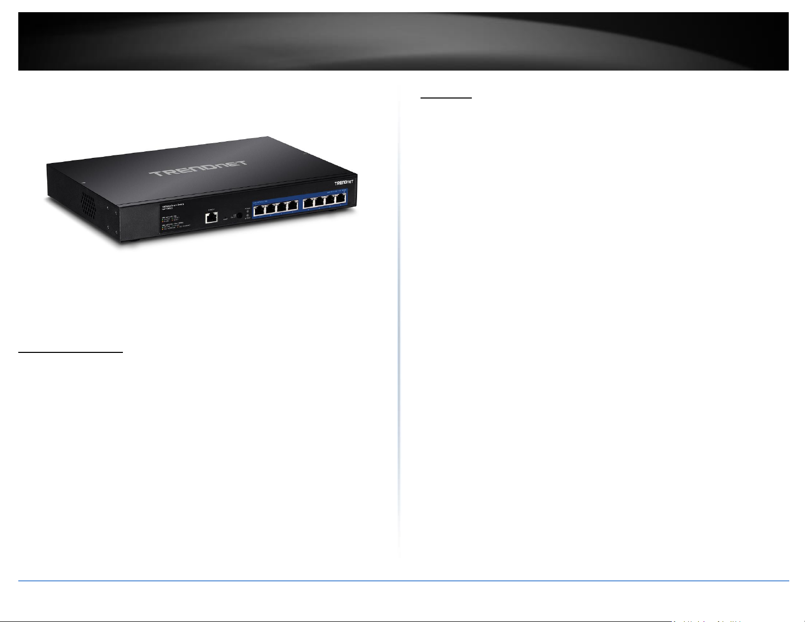
TRENDnet’s 8-Port 10G Easy Smart Switch with 8 x 10GBASE-T ports, model TEG-7080ES,
is a cost-effective switch solution for high-speed 10 Gigabit network server connections.
This easy smart switch features the most commonly used managed switch features,
reducing unnecessary switch complexity. The web-based management interface offers
features for traffic control, troubleshooting, access controls, and monitoring.
TRENDnet’s TEG-7080ES allows for simple network integration into your SMB network
High-Speed 10GBASE-T
Offers eight 10GBASE-T Ethernet ports for high-speed network uplink or downlink NAS /
access server connections providing a cost-effective solution in adding 10G link
capability to an SMB network.
TEG-7080ES
Package Contents
In addition to your switch, the package includes:
Quick Installation Guide
Power cord
RJ-45 to RS-232 console cable (1 m / 3.28 ft.)
Rack mount kit
If any package contents are missing or damaged, please contact the retail store, online
retailer, or reseller/distributor from which the product was purchased.
Easy Smart Management
Provides an easy to use web-based GUI management for reduced switch configuration
complexity and offers a combination of more commonly used SMB management
features for easy deployment.
Integration Flexibility
Managed features include access control lists, VLAN, IGMP Snooping, and QoS for
flexible network integration
Hardware
Provides 8 x 10GBASE-T ports for high-speed network uplink or downlink server
connections, and 1U rack mountable.
Smart Fan
Smart fan saves energy by auto-adjusting the fan speed and use based on cooling needs.
© Copyright 2018 TRENDnet. All Rights Reserved.
Page 4
TRENDnet User’s Guide
TEG-7080ES
2
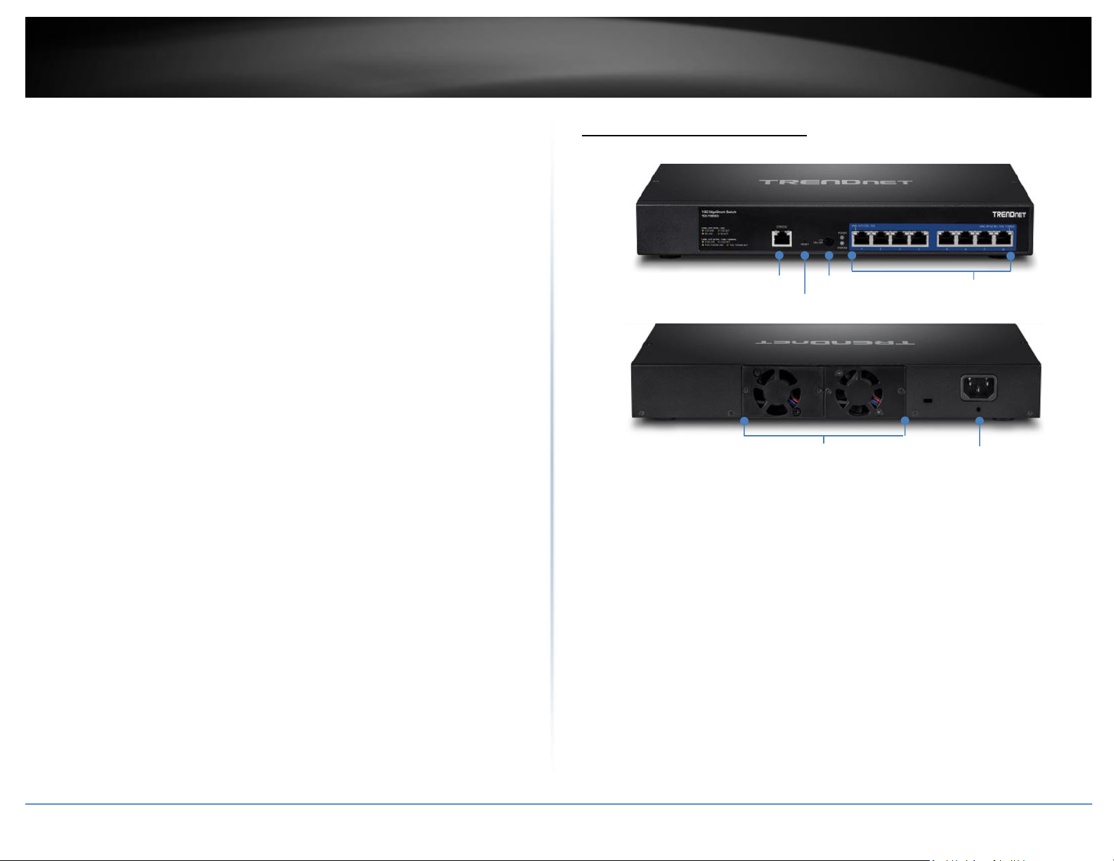
Console Port
Reset Button
LED on/off
10GBASE-T ports
Smart fans
Power port
Network Management
A broad range of network configurations are supported by: 802.3ad link aggregation,
802.1Q VLAN, bandwidth controls, IGMP, loopback detection, port mirroring and 802.1p
(QoS).
Product Hardware Features
Troubleshooting
Traffic statistics and a convenient cable diagnostic test aid in network troubleshooting.
© Copyright 2018 TRENDnet. All Rights Reserved.
LED on/off – Press and hold to turn LED lights on or off
LED Indicators – Indicator for device Power and System status.
10GBASE-T Ethernet Ports (1-8) – Connect network devices or servers
Console Port – – Use the included RJ-45 to RS-232 serial console cable to
access the out-of-band command line interface management.
Reset Button- Press and hold this button for 8 seconds and release to
reset the switch to factory defaults. The ports LEDs will turn off to
indicate that the reset was initiated.
Power Port – Connect the power cord to start up the device (supports
AC 100 – 240V, 50-60Hz)
Page 5

TRENDnet User’s Guide
TEG-7080ES
3
On
:
When the POWER LED light is on, the device is receiving
power.
Off
:
When the Power turns off, the power adapter is not
connected or the device is not receiving power.
On (Amber)
:
When the amber SYSTEM LED light is on, the device is
booting up
On (Green)
:
When the green SYSTEM LED light is on, the device has
finished booting and is ready for operation.
Click Once
:
When the LED ON/OFF button is clicked, the device will
disable all LED lights aside from the POWER LED.
Hold 3
Seconds
:
When the LED ON/OFF button is held for 3 seconds, the
device will automatically begin running cable diagnostics.
On (Amber)
:
When the Link/Act LED is on, the link established is
operating at 5Gbps speeds.
On (Green)
:
When the Link/Act LED is on, the link established is
operating at 10Gbps speeds.
Off
When the Link/Act LED light is off, there is no
established connection.
On (Amber)
:
When the Link/Act LED is on, the link established is
operating at 100/1000Mbps speeds.
On (Green)
:
When the Link/Act LED is on, the link established is
operating at 10Gbps speeds.
Off
When the Link/Act LED light is off, there is no
established connection.
Blinking
(Green)
:
When the CABLE DIAGNOSTIC LED is blinking Green, the
port is executing cable diagnostics.
Blinking
(Amber)
When the CABLE DIAGNOSTIC LED is blinking Amber,
the link is not established.
On (Green)
When the CABLE DIAGNOSTIC LED is on, the diagnostic
has determined a healthy connection.
On (Amber)
:
When the CABLE DIAGNOSTIC LED is on, the diagnostic
has determined an unhealthy connection.
10GBASE-T Ethernet Port LEDs
Link/Activity (Left hand LED - per port)
LED Indicators
POWER LED
SYSTEM LED
LED ON/OFF Button
Link/Activity (Right hand LED - per port)
10GBASE-T Ethernet Port LEDs
Cable Diagnostic (Per port)
© Copyright 2018 TRENDnet. All Rights Reserved.
Page 6
TRENDnet User’s Guide
TEG-7080ES
4
Switch Installation
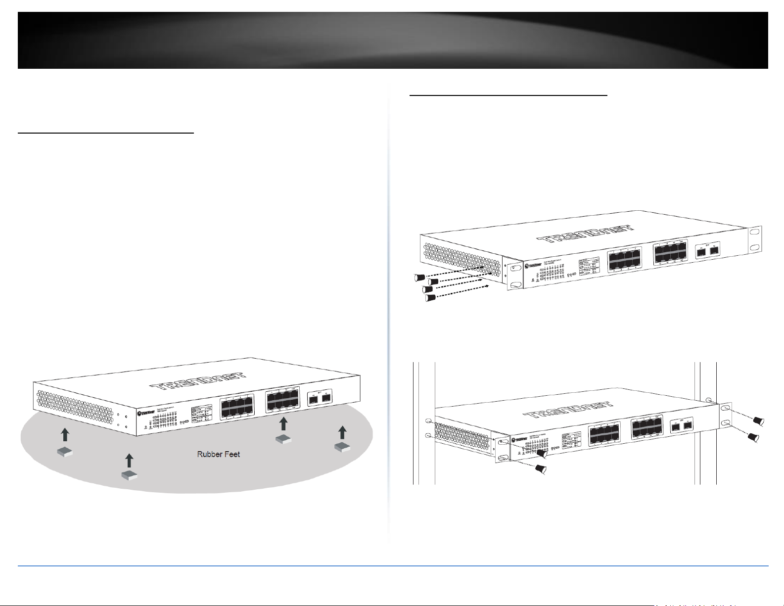
Desktop Hardware Installation
The site where you install the switch may greatly affect its performance. When
installing, consider the following pointers:
Note: The switch model may be different than the one shown in the example
illustrations.
Install the Switch in a fairly cool and dry place.
Install the Switch in a site free from strong electromagnetic field generators (such
as motors), vibration, dust, and direct exposure to sunlight.
Leave at least 10cm of space at the front and rear of the hub for ventilation.
Install the Switch on a sturdy, level surface that can support its weight, or in an
EIA standard-size equipment rack. For information on rack installation, see the
next section, Rack Mounting.
When installing the Switch on a level surface, attach the rubber feet to the
bottom of each device. The rubber feet cushion the hub and protect the hub
case from scratching.
Rack Mount Hardware Installation
The switch can be mounted in an EIA standard-size, 19-inch rack, which can be placed in
a wiring closet with other equipment. Attach the mounting brackets at the switch’s
front panel (one on each side), and secure them with the provided screws.
Note: The switch model may be different than the one shown in the example
illustrations.
Then, use screws provided with the equipment rack to mount each switch in the rack.
© Copyright 2018 TRENDnet. All Rights Reserved.
Page 7
TRENDnet User’s Guide
TEG-7080ES
5
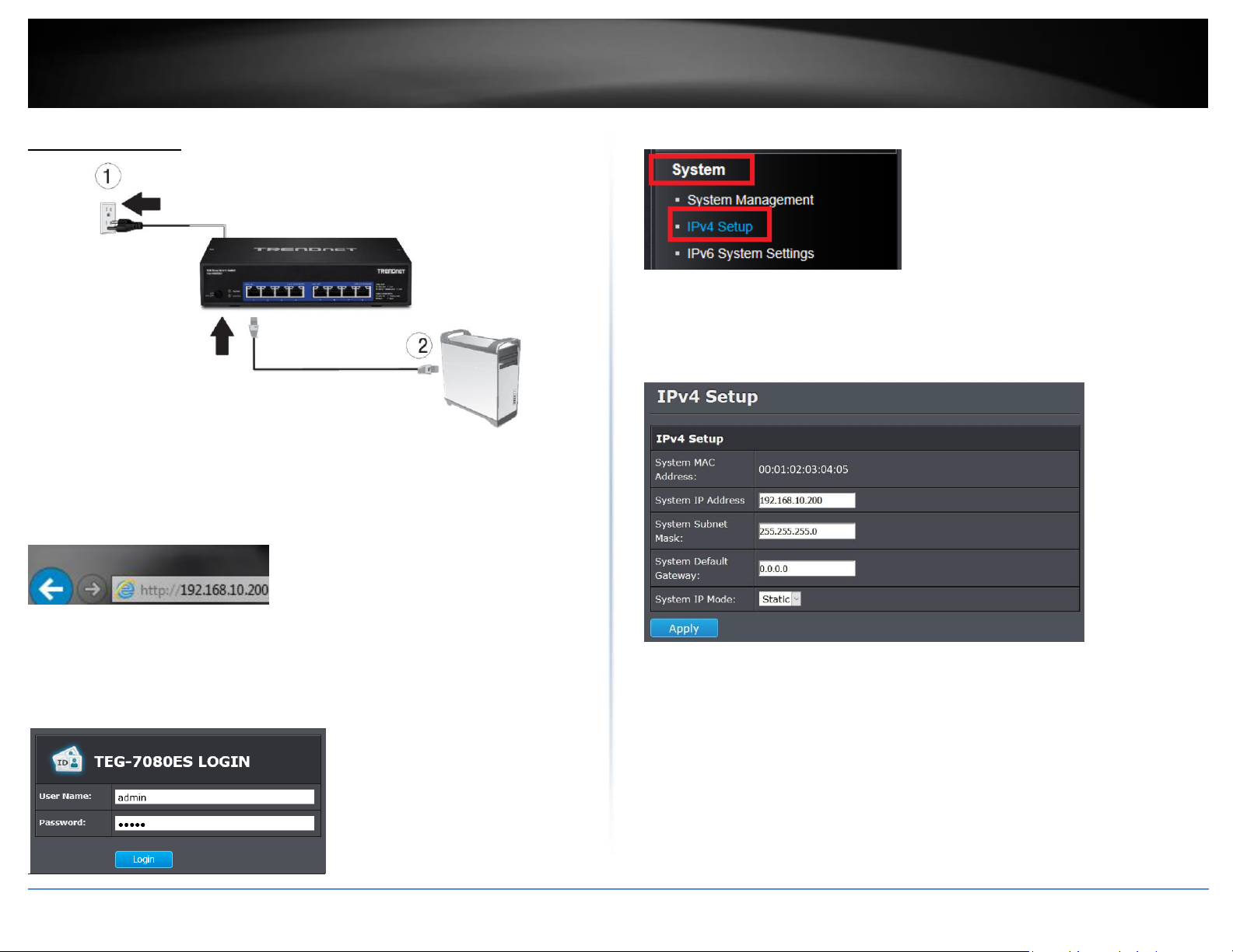
Basic Installation
3. Assign a static IP address to your computer’s network adapter in the subnet of
192.168.10.x (e.g. 192.168.10.25) and a subnet mask of 255.255.255.0.
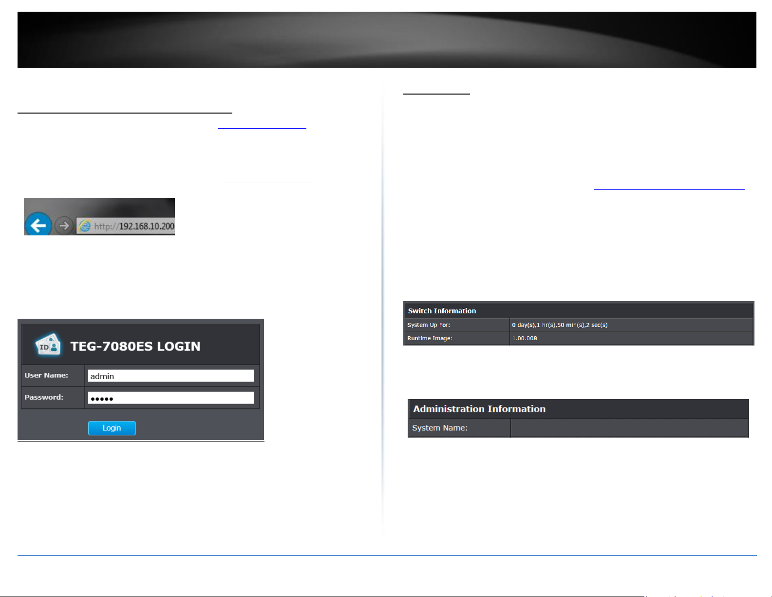
4. Open your web browser, and type the IP address of the switch in the address bar, and
then press Enter. The default IP address is 192.168.10.200.
6. Click System and then click IPv4 Setup.
7. Configure the switch IP address settings to be within your network subnet, then click
Apply to save changes.
Note: You may need to modify the static IP address settings of your computer’s network
adapter to IP address settings within your subnet in order to regain access to the switch.
5. Enter the User Name and Password, and then click Login. By default:
User Name: admin
Password: admin
Note: User name and password are case sensitive.
© Copyright 2018 TRENDnet. All Rights Reserved.
5. The browser will automatically use the new IP address to reconnect to the device and
bring you back to the login page. Re-login using the default User Name and Password.
Page 8
6
TRENDnet User’s Guide
TEG-7080ES
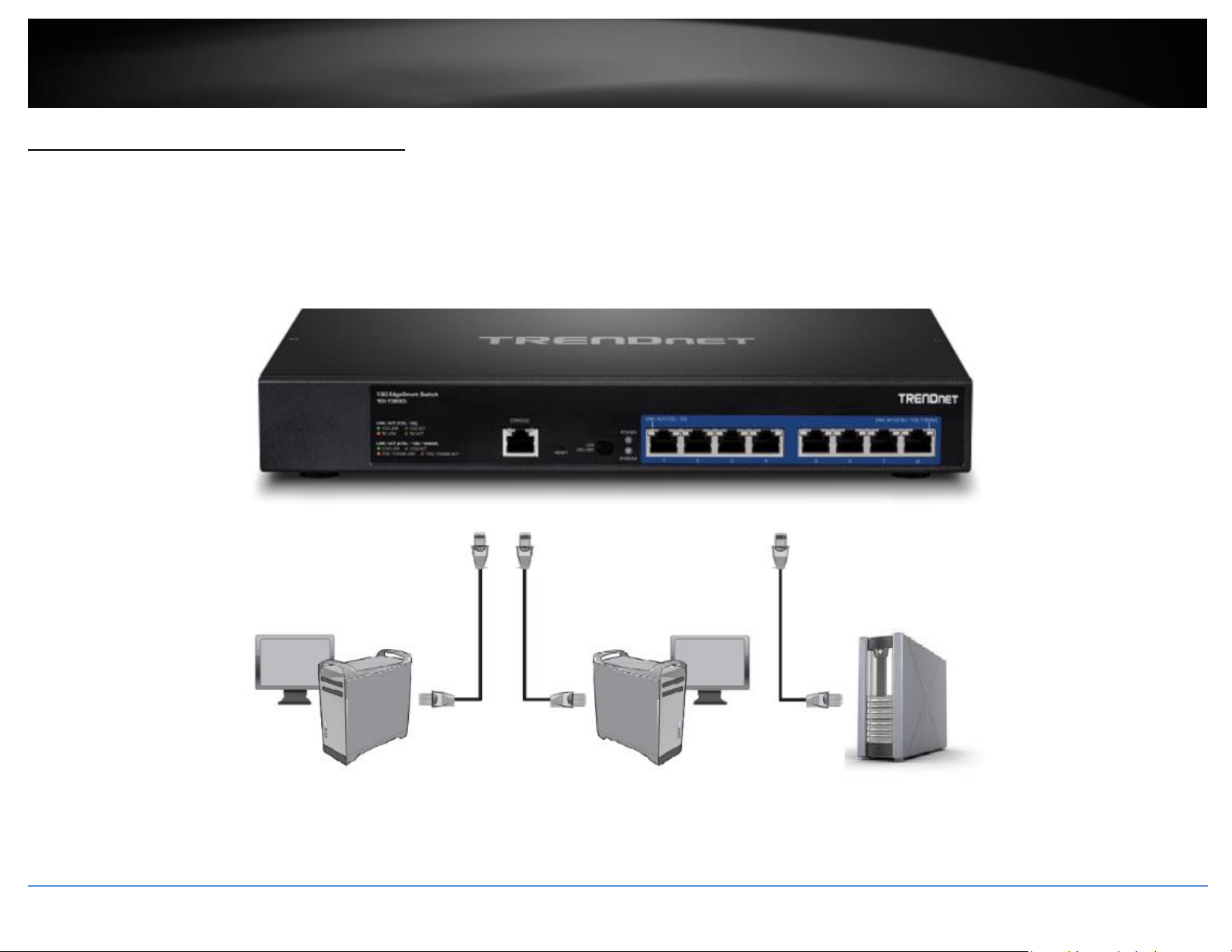
Connect additional devices to your switch
You can connect computers/servers or other network devices to your switch using Ethernet cables to connect them to one of the available 10GBASE-T Ethernet Ports. Check the status of
the LED indicators on the front panel of your switch to ensure the physical cable connection from your computer or device. You can use either the 10GBASE-T Ethernet ports connections
as network uplinks.
Note: If you encounter issues connecting to your network, there may be a problem with your computer or device network settings. Please ensure that your comp uter or device network
settings (also called TCP/IP settings) are configured properly within the network subnet your switch is connected.
10G Capable Workstation
© Copyright 2018 TRENDnet. All Rights Reserved.
10G Capable Workstation
Server
Page 9
7
TRENDnet User’s Guide
TEG-7080ES
Configure your switch
Access your switch management page
Note: Your switch default management IP address http://192.168.10.200 is accessed
through the use of your Internet web browser (e.g. Internet Explorer®, Firefox®,
Chrome™, Safari®, Opera™) and will be referenced frequently in this User’s Guide.
1. Open your web browser and go to the IP address http://192.168.10.200. Your switch
will prompt you for a user name and password.
2. Enter the user name and password. By default:
User Name: admin
Password: admin
Note: User Name and Password are case sensitive.
System Info
View your switch status information
System Info
You may want to check the general system information of your switch such as firmware
version and system uptime. Other information includes administration information,
IPv4 and IPv6 information.
1. Log into your switch management page (see “Access your switch management page”
on page 7).
2. Click on System Info.
System Information
System Up For – The duration your switch has been running continuously without
a restart/power cycle (hard or soft reboot) or reset.
Runtime Image: The current software or firmware version your switch is running.
Administration Information
System Name – Displays the identifying system name of your switch. This
information can be modified under the System section.
© Copyright 2018 TRENDnet. All Rights Reserved.
Page 10
8
TRENDnet User’s Guide
TEG-7080ES
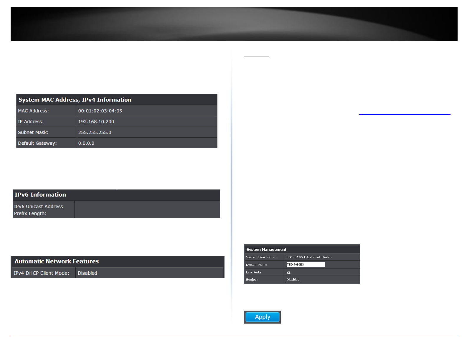
System MAC Address, IPv4 Information
MAC Address: Displays the switch system MAC address.
IP Address – Displays the current IPv4 address assigned to your switch.
Subnet Mask – Displays the current IPv4 subnet mask assigned to your switch.
Default Gateway – Displays the current gateway address assigned to your switch.
IPv6 Information
IPv6 Address: Displays the current IPv6 address and prefix assigned to your
switch.
Automatic Network Features
IPv4 DHCP Client Mode: Displays if your switch IPv4 address setting is set to
DHCP client.
System
Set your system information
System > System Management
This section explains how to assign a name for the switch. This information helps in
identifying each specific switch among other switches in the same local area network.
Entering this information is optional.
1. Log into your switch management page (see “Access your switch management page”
on page 7).
2. Click on System
3. Review the System Management settings. When you have completed making
changes, click Apply to save the settings.
System Description - Specifies the switch model. You cannot change this
parameter.
System Name - Specifies a name for the switch, the name is optional and may
contain up to 15 characters.
Link Ports - Specifies the ports with an established link.
Bonjour – A discovery protocol that enables automatic discovery of services
and devices within the IP networks. Bonjour is disabled by default.
4. Click Apply to save configuration changes to the NV-RAM to ensure that if the switch
is rebooted or power cycled, the configuration changes will still be applied.
© Copyright 2018 TRENDnet. All Rights Reserved.
Page 11
9
TRENDnet User’s Guide
TEG-7080ES
Set your IPv4 settings
System > IPv4 Setup
This section allows you to change your switch IPv4 address settings. Typically, the IP
address settings should be changed to match your existing network subnet in order to
access the switch management page on your network.
Default Switch IPv4 Address: 192.168.10.200
Default Switch IPv4 Subnet Mask: 255.255.255.0
1. Log into your switch management page (see “Access your switch management page”
on page 7).
2. Click on System, and click on IPv4 Setup.
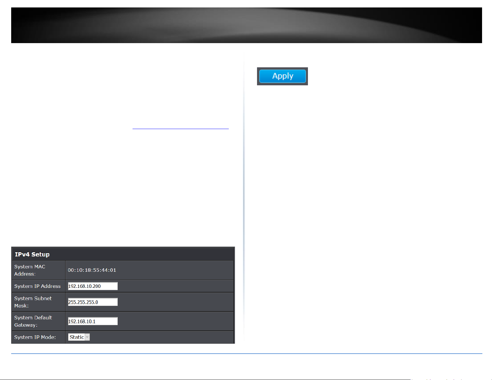
3. Review the settings. When you have completed making changes, click Apply to save
the settings.
System MAC Address: Displays the switch MAC address information.
System IP Address: Enter the new switch IP address. (e.g. 192.168.200.200)
System Subnet Mask: Enter the new switch subnet mask. (e.g. 255.255.255.0)
System Default Gateway: Enter the default gateway IP address. (e.g.
192.168.200.1 or typically your router/gateway to the Internet).
System IP Mode: Click the drop-down list and select Static to manually specify
your IP address settings or DHCP to allow your switch to obtain IP address
settings automatically from a DHCP server on your network.
4. Click Apply to save configuration changes to the NV-RAM to ensure that if the switch
is rebooted or power cycled, the configuration changes will still be applied.
© Copyright 2018 TRENDnet. All Rights Reserved.
Page 12

10
TRENDnet User’s Guide
TEG-7080ES
Set your IPv6 settings
System > IPv6 System Settings
Internet Protocol version 6 (IPv6) is a new IP protocol designed to replace IP version 4
(IPv4). The IPv6 address protocol meets the current requirements of new applications
and the never ending growth of the Internet. The IPv6 address space makes more
addresses available but it must be approached with careful planning. Successful
deployment of IPv6 can be achieved with existing IPv4 infrastructures. With proper
planning and design, the transition between IP version 4 and 6 is possible today as well.
Use the IPv6 System Settings page to configure the IPv6 network interface, which is the
logical interface used for in-band connectivity with the switch via all of the switch's
front-panel ports. The configuration parameters associated with the switch's network
interface do not affect the configuration of the front-panel ports through which traffic is
switched or routed.
1. Log into your switch management page (see “Access your switch management page”
on page 7).
2. Click on System, and click on IPv6 System Settings.
3. Review the settings. When you have completed making changes, click Apply to save
the settings.
IPv6 State: The IPv6 address for the IPv6 network interface is set in auto
configuration mode if this option is enabled. The default value is Disable. Auto
configuration can be enabled only when DHCPv6 is not enabled on any of the
management interfaces. DHCPv6 Client: This option only displays when
DHCPv6 is enabled.
IPv6 Unicast Address / Prefix Length: The IPv6 Unicast Address is an identifier
for a single interface, on a single node. A packet that is sent to a unicast
address is delivered to the interface identified by that address. Add the IPv6
prefix and prefix length to the IPv6 System Settings interface.
Link Local Address Settings / Prefix Length: A link local address has a prefix of
FE80, is not routable, and can be used for communication only on the local
network. Only one link local address is supported. If a link local address exists
on the interface, this entry replaces the address in the configuration.
4. Click Apply to save configuration changes to the NV-RAM to ensure that if the switch
is rebooted or power cycled, the configuration changes will still be applied.
© Copyright 2018 TRENDnet. All Rights Reserved.
Page 13

11
TRENDnet User’s Guide
TEG-7080ES
Restrict access to switch management page
System > IP Access List
This section allows you to define or restrict access to the switch management page to a
list of specific IP addresses.
1. Log into your switch management page (see “Access your switch management page”
on page 7).
2. Click on System, and click on IP Access List.
3. Review the settings.
First, enter the IPv4 or IPv6 address to allow access and click Apply to save entries into
the IP Access List. A maximum of 5 IP addresses can be added to the IP Access List.
For each entry, the access list will populate. You can remove IP addresses from the IP
Access List simply by deleting the entries and clicking Apply.
To limit access to your switch management page to a single user at a time, simply check
the Limit Single User Access box and click Apply. Access to the switch management
page will automatically timeout after 5 minutes.
Change administrator password and add accounts
System > Administration
This section explains how to change the administrator password create additional
administrative user accounts for access to the switch management page.
1. Log into your switch management page (see “Access your switch management page”
on page 7).
2. Click on System, and click on Administration.
To change the administrator password, first enter the current password and then enter
and confirm the new password in the avaliable cells. Click Apply to save the new
password.
Note: The password consists of up to 12 alphanumeric characters.
4. Click Apply to save configuration changes to the NV-RAM to ensure that if the switch
is rebooted or power cycled, the configuration changes will still be applied.
4. Click Apply to save configuration changes to the NV-RAM to ensure that if the switch
is rebooted or power cycled, the configuration changes will still be applied.
© Copyright 2018 TRENDnet. All Rights Reserved.
Page 14

12
TRENDnet User’s Guide
TEG-7080ES
Physical Interface
Configure Physical Interfaces
Physical Interface
This section allows you to configure the physical port parameters such as speed, duplex,
flow control, and jumbo frames. This section also reports the current link status of each
port and negotiated speed/duplex.
1. Log into your switch management page (see “Access your switch management page”
on page 7).
2. Click on Physical Interface.
3. Review the settings. Click Apply to save changes.
Port - Specifies the port number. The All value indicates ports 01 through 08 on
the Switch. You cannot change this parameter.
Type - This parameter indicates the port type. On the Switch, the port type can
be 10Gbps/Full, 5Gbps/Full, 2.5Gbps/Full, 1000Mbps/Full, and 100Mbps/Full.
Link Status - This parameter indicates the status of the link between the port
and the end node connected to the port. The possible values are:
o Up -This parameter indicates a valid link exists between the port and
the end node.
o Down -This parameter indicates the port and the end node have not
established a valid link.
Admin. Status: This parameter indicates the operating status of the port. You
can use this parameter to enable or disable a port. You may want to disable a
port and prevent packets from being forwarded if a problem occurs with the
node or cable connected to the port. You can enable the port to resume
normal operation after the problem has been fixed. You can also disable an
unused port to secure it from unauthorized connections. The possible values
are:
o Enabled - This parameter indicates the port is able to send and receive
Ethernet frames.
o Disabled - This parameter indicates the port is not able to send and
receive Ethernet frames.
Mode: This parameter indicates the speed and duplex mode settings for the
port. You can use this parameter to set the speed and duplex mode of a port.
The possible settings are:
o Auto -This parameter indicates the port is using Auto-Negotiation to
set the maximum operating speed and duplex mode. The actual
operating speed and duplex mode of the port are displayed in port
Type (for example, “1000Mbps” for 1000 Mbps full duplex mode) after
a port establishes a link with an end node.
o 10000/Full -This parameter indicates the port is configured for 10Gbps
operation in full-duplex mode.
o 5000/Full -This parameter indicates the port is configured for 5Gbps
operation in full-duplex mode.
o 2500/Full -This parameter indicates the port is configured for 2.5Gbps
operation in full-duplex mode.
o 1000/Full -This parameter indicates the port is configured for
1000Mbps operation in full-duplex mode.
o 100/Full -This parameter indicates the port is configured for 100Mbps
operation in full-duplex mode.
Note: When selecting a Mode setting, the following points apply:
o When a twisted-pair port is set to Auto-Negotiation, the end node should
also be set to Auto-Negotiation to prevent a duplex mode mismatch.
o A switch port using Auto-Negotiation defaults to half-duplex if it detects
that the end node is not using Auto-Negotiation. This can result in a
mismatch if the end node is operating at a fixed duplex mode of full-duplex.
To avoid this problem when connecting an end node with a fixed duplex
mode of full-duplex to a switch port, disable Auto-Negotiation on the port
and set the port’s speed and duplex mode manually.
Jumbo: This parameter indicates whether or not jumbo frames can be accepted
by the switch. You may want to activate jumbo frames when your switch will
transmit video and audio files. The possible values are:
o Enabled -This parameter indicates the port is permitted to accept
jumbo frames.
© Copyright 2018 TRENDnet. All Rights Reserved.
Page 15

13
TRENDnet User’s Guide
TEG-7080ES
o Disabled -This parameter indicates the port is not permitted to accept
jumbo frames.
Note: When QoS is enabled on a port, the Jumbo frame parameter cannot be
enabled.
Flow Ctrl: Flow Control, This parameter reflects the current flow control setting
on the port. The switch uses a special pause packet to notify the end node to
stop transmitting for a specified period of time. The possible values are:
o Enabled - This parameter indicates that the port is permitted to use
flow control.
o Disabled - This parameter indicates that the port is not permitted to
use flow control.
5. Click Apply to save configuration changes to the NV-RAM to ensure that if the switch
is rebooted or power cycled, the configuration changes will still be applied.
the cables prior to configuring the ports can create loops in your network topology.
Loops can result in broadcast storms which can severely limited the effective bandwidth
of your network.
1. Log into your switch management page (see “Access your switch management page”
on page 7).
2. Click on Bridge, click on Trunk Config, and click on Trunking.
3. Review the settings. For each trunk group, click Apply to save changes.
Distribution Criterion: This parameter indicates the criterion to balance traffic
between members of the Trunk Group. This allows the switch to specify criteria
to allow for the most efficient traffic distribution. The optimal choice will
depend on your network environment.
o SA-This parameter indicates the switch is distributing traffic to links
within the trunk group based on the Source MAC address only.
o DA- This parameter indicates the switch is distributing traffic to links
within the trunk group based on the Destination MAC address only.
o SA + DA- This parameter indicates the switch is distributing traffic to
links within the trunk group based on the Source MAC address and
Destination MAC address.
Bridge
Configure Trunking
Bridge > Trunk Config > Trunking
Important Note: Do not connect the cables of a port trunk to the ports on the switch
until you have configured the ports on both the switch and the end nodes. Connecting
© Copyright 2018 TRENDnet. All Rights Reserved.
Trunk Group Settings: This parameter allows users to create Trunk Groups based
on specified ports. The trunking function enables the cascading of two or more
ports for a combined larger total bandwidth. Up to 4 trunk groups may be
created, each supporting up to 8 ports. Select the ports to be trunked together
in the desired Trunk Group, and click Apply to activate the selected trunking
groups.
Page 16

14
TRENDnet User’s Guide
TEG-7080ES
Configure port mirror settings
Bridge > Mirroring
Port mirroring allows you to monitor the ingress and egress traffic on a port by having
the traffic copied to another port where a computer or device can be set up to capture
the data for monitoring and troubleshooting purposes.
1. Log into your switch management page (see “Access your switch management page”
on page 7).
2. Click on Bridge, and click on Mirroring.
4. Click Apply to save configuration changes to the NV-RAM to ensure that if the switch
is rebooted or power cycled, the configuration changes will still be applied.
3. Review the settings. Click Apply to save changes.
Mirror Setting – Check the Enable Mirror box to enable port mirroring.
Mirroring Port Setting – Select desired Mirror ports and designate a Mirror To
port for traffic to be copied for data monitoring and troubleshooting
Note: The Mirror Ports and Mirror-To ports cannot belong to the same trunk group.
4. Click Apply to save configuration changes to the NV-RAM to ensure that if the switch
is rebooted or power cycled, the configuration changes will still be applied.
© Copyright 2018 TRENDnet. All Rights Reserved.
Page 17

15
TRENDnet User’s Guide
TEG-7080ES
Enable loopback detection
Bridge > Loopback Detection
The loopback detection feature allows the switch to detect and prevent disruption from
loops that occur on uplink or downlink switches directly connected to your switch.
1. Log into your switch management page (see “Access your switch management page”
on page 7).
2. Click on Bridge and click on Loopback Detection.
3. Review the settings.
Enable Loop Detection – This selection enables the Loopback Detection feature
for each port.
Port – Defines switch port and corresponding Loop Status
Loop Status – Defines if a Loop is detected and the link status.
Configure IGMP Snooping Settings
Bridge > IGMP Snooping > IGMP Snooping Settings
1. Log into your switch management page (see “Access your switch management page”
on page 7).
2. Click on Bridge, click on IGMP Snooping, and click on IGMP Snooping Settings.
3. Review the settings. Click Apply to save the settings.
IGMP Snooping Enable – Select to enable IGMP Snooping feature
VLAN ID for IGMP snooping – This parameter allows users to define VLAN IDs
to enable IGMP snooping.
Block Unknown Multicast Address Enable – Enabling this feature will
automatically block unknown multicasting addresses.
4. Click Apply to save configuration changes to the NV-RAM to ensure that if the switch
is rebooted or power cycled, the configuration changes will still be applied.
4. Click Apply to save configuration changes to the NV-RAM to ensure that if the switch
is rebooted or power cycled, the configuration changes will still be applied.
© Copyright 2018 TRENDnet. All Rights Reserved.
Page 18

16
TRENDnet User’s Guide
TEG-7080ES
Configure Storm Control
Bridge > Bandwidth Control > Storm Control
This section allows you to configure the storm control settings for the switch.
1. Log into your switch management page (see “Access your switch management page”
on page 7).
2. Click on Bridge, click on Bandwidth Control, and click on Storm Control.
3. Review the settings for each port. Click Apply to save the settings.
Storm Control Type – Enabling this feature provides bidirectional bandwidth
control. Once enabled, any excessive packets will be discarded.
Storm Control Rate – This parameter defines the Ingress/Egress Storm Control
Rates ( 1/2/4/8/16/64/128/256/512Mbps)
4. Click Apply to save configuration changes to the NV-RAM to ensure that if the switch
is rebooted or power cycled, the configuration changes will still be applied.
Set Ingress / Egress Rate Limiting
Bridge > Bandwidth Control > Rate Limiting
This section allows you to set the ingress (receive) and egress (transmit) rate for each
switch port.
1. Log into your switch management page (see “Access your switch management page”
on page 7).
2. Click on Bridge, click on Bandwidth Control, and click on Rate Limiting.
3. Review the settings for each port. Click Apply to save the settings.
Port – Lists the switch ports. Users can click on the port number to change Rate
Limiting changes to the respective port.
Ingress Rate – Displays the Ingress Rate Limit value.
Egress Rate- Displays the Egress Rate Limit Value.
© Copyright 2018 TRENDnet. All Rights Reserved.
4. Click Apply to save configuration changes to the NV-RAM to ensure that if the switch
is rebooted or power cycled, the configuration changes will still be applied.
Page 19

17
TRENDnet User’s Guide
TEG-7080ES
Bridge > VLAN > Tagged VLAN
A VLAN is a group of ports that can be anywhere in the network, but communicate as
though they were in the same area.
VLANs can be easily organized to reflect department groups (such as R&D, Marketing),
usage groups (such as e-mail), or multicast groups (multimedia applications such as
video conferencing), and therefore help to simplify network management by allowing
users to move devices to a new VLAN without having to change any physical
connections.
1. Log into your switch management page (see “Access your switch management page”
on page 7).
2. Click on Bridge, click on VLAN, and click on Tagged VLAN and then Create New VLAN.
3. Review the settings.
New VLAN ID – Enter the VLAN ID for the new VLAN.
Tag Settings –Clicking the icons under each port will change the member state
from Not Member, Tag egress packets, and Untag egress packets. Clicking the
All icon will change tag settings for all ports.
On a port, the tag information within a frame is examined when it is received to
determine if the frame is qualified as a member of a specific tagged VLAN. If it is, it is
eligible to be switched to other member ports of the same VLAN. If it is determined that
the frame’s tag does not conform to the tagged VLAN, the frame is discarded. Since
these VLAN ports are VLAN aware and able to read VLAN VID tagged information on a
frame and forward to the appropriate VLAN, typically tagged VLAN ports are used for
uplink and downlink to other switches to carry and forward traffic for multiple VLANs
across multiple switches. Tagged VLAN ports can be included as members for multiple
VLANs. Computers and other edge devices are not typically connected to tagged VLAN
ports unless the network interface on these device can be enabled to be VLAN aware.
Select the tagged VLAN ports to add to the new VLAN.
Note: By default, the default VLAN VID 1 is set as the Management VLAN.
4. Click Apply to save configuration changes to the NV-RAM to ensure that if the switch
is rebooted or power cycled, the configuration changes will still be applied.
5. The created Tagged VLANs will be displayed on the Tagged VLAN page. This switch
supports a maximum of 16 VLANs.
© Copyright 2018 TRENDnet. All Rights Reserved.
Page 20

18
TRENDnet User’s Guide
TEG-7080ES
Configure VLAN Port Settings
Bridge > VLAN > Port Settings
In this section, you can modify the port VID settings.
1. Log into your switch management page (see “Access your switch management page”
on page 7).
2. Click on Bridge, click on VLAN, and click on Port Settings.
3. Review the settings for each port. Click Apply to save settings.
Port – Displays the port number
PVID – Allows users to assign VLAN IDs for untagged packets through 802.1q
VLAN.
4. Click Apply to save configuration changes to the NV-RAM to ensure that if the switch
is rebooted or power cycled, the configuration changes will still be applied.
Configure the VLAN forwarding Table
Bridge > VLAN > Dynamic Forwarding Table
1. Log into your switch management page (see “Access your switch management page”
on page 7).
2. Click on Bridge, click on VLAN, and click on Dynamic Forwarding Table.
3. This table displays the MAC addresses learned by the switch, along with responding
VLAN, and Port (including trunk groups).
If the entries span multiple pages, you can click the Arrow buttons to navigate the
pages.
© Copyright 2018 TRENDnet. All Rights Reserved.
Page 21

19
TRENDnet User’s Guide
TEG-7080ES
QoS (Quality of Service)
When a port on an Ethernet switch becomes oversubscribed, its egress queues contain
more packets than the port can handle in a timely manner. In this situation, the port
may be forced to delay the transmission of some packets, resulting in the delay of
packets reaching their destinations. A port may be forced to delay transmission of
packets while it handles other traffic, and, in some situations, some packets destined to
be forwarded to an oversubscribed port from other switch ports may be discarded.
Minor delays are often of no consequence to a network or its performance. But there
are applications, referred to as delay or time sensitive applications, which can be
impacted by packet delays. Voice transmission and video conferences are two examples.
If packets carrying data in either of these cases are delayed from reaching their
destination, the audio or video quality may suffer. This is where Class of Service (CoS) is
of value. It allows you to manage the flow of traffic through a switch by having the
switch ports give higher priority to some packets, such as delay sensitive traffic, over
other packets. This is referred to as prioritizing traffic.
Set IEEE 802.1P settings
Bridge > QoS > IEEE 802.1P QoS
1. Log into your switch management page (see “Access your switch management page”
on page 7).
2. Click on Bridge and click on QoS.
3. By default, the QoS Mode setting is set to IEEE 802.1P QoS.
4. Review the fixed IEEE 802.1P QoS settings. These Traffic Classes are fixed to their
respective queues (Queue 0, Queue 1, Queue, 2, Queue 3) and cannot be changed.
o IEEE 802.1p sets a 3-bit value in the MAC header to indicate prioritization.
This 3-bit value provides priority levels ranging from 0 to 7 (i.e., a total of 8
levels), with level 7 representing the highest priority. This permits packets
to cluster and form different traffic classes. Thus, when network
congestion occurs, those packets that have higher priorities will receive
preferential treatment while low priority packets will be kept on hold.
6. Change the Scheduling Method Settings to define the hierarchy and parameters for
the QoS Mode application. Click Apply to save the settings.
• Weighted Round Robin - The port transmits a set number of packets from each
queue, in a round robin fashion, so that each has a chance to transmit traffic.
• All-High-Before-Low - The port transmits all packets out of higher priority
queues before transmitting any from the lower priority queues.
7. Click Apply to save configuration changes to the NV-RAM to ensure that if the switch
is rebooted or power cycled, the configuration changes will still be applied.
© Copyright 2018 TRENDnet. All Rights Reserved.
Page 22

20
TRENDnet User’s Guide
TEG-7080ES
Set Port-Based QoS
Bridge > QoS > Port-Based QoS
The Port-Based QoS mode allows users to change priority port settings for all available
ports. This setting supports four Queues (Queue 0, Queue 1, Queue 2, Queue 3), all of
which hold different weights. Ports handling high priority traffic, such as video or voice
application, can be assigned higher priority queues (Queue 3) for optimized
performance.
1. Log into your switch management page (see “Access your switch management page”
on page 7).
2. Click on Bridge and select QoS
3. Change QoS Mode Setting to Port-Based QoS.
3. For each port, select a Queue in the Priority Settings. Click Apply to save the settings.
5. Change the Scheduling Method Settings to define the hierarchy and parameters for
the QoS Mode application. Click Apply to save the settings.
• Weighted Round Robin - The port transmits a set number of packets from each
queue, in a round robin fashion, so that each has a chance to transmit traffic.
• All-High-Before-Low - The port transmits all packets out of higher priority
queues before transmitting any from the lower priority queues.
6. Click Apply to save configuration changes to the NV-RAM to ensure that if the switch
is rebooted or power cycled, the configuration changes will still be applied.
© Copyright 2018 TRENDnet. All Rights Reserved.
Page 23

21
TRENDnet User’s Guide
TEG-7080ES
Statistics
Statistics provide important information for troubleshooting switch problems at the port
level. The Switch Management page provides one statistics charts for monitoring Traffic
Information
View Traffic Information Statistics
Statistics > Traffic Information
1. Log into your switch management page (see “Access your switch management page”
on page 7).
2. Click on Statistics and click on Traffic Information
3. View the Traffic Information Statistics.
Tx – Displays the total number of bytes transmitted per port.
Rx – Displays the total number of bytes received per port.
Clear Counter – Clears the Traffic Information and resets the counter.
Refresh – Refreshes the Statistics table with the updated Traffic Information.
Switch Maintenance
Upgrade your switch firmware
TRENDnet may periodically release firmware upgrades that may add features or fix
problems associated with your TRENDnet switch model and version. To check if there is
a firmware upgrade available for your device, please check your TRENDnet model and
version using the link. http://www.trendnet.com/downloads/
In addition, it is also important to verify if the latest firmware version is newer than the
one your switch is currently running. To identify the firmware that is currently loaded on
your switch, log in to the switch, click on the System Info section or click on Tools and
click on Firmware Upgrade. The firmware used by the switch is listed as Runtime Image
or Image Version. If there is a newer version available, also review the release notes to
check if there were any new features you may want or if any problems were fixed that
you may have been experiencing.
1. If a firmware upgrade is available, download the firmware to your computer.
2. Unzip the file to a folder on your computer.
Please note the following:
Do not interrupt the firmware upgrade process. Do not turn off the device or
press the Reset button during the upgrade.
If you are upgrade the firmware using a laptop computer, ensure that the laptop
is connected to a power source or ensure that the battery is fully charged.
Disable sleep mode on your computer as this may interrupt the firmware upgrade
process.
Do not upgrade the firmware using a wireless connection, only using a wired
network connection.
Any interruptions during the firmware upgrade process may permanently
damage your switch.
© Copyright 2018 TRENDnet. All Rights Reserved.
Page 24

22
TRENDnet User’s Guide
TEG-7080ES
Firmware Upgrade via HTTP Settings
Tools > Firmware Upgrade > via HTTP
1. Log into your switch management page (see “Access your switch management page”
on page 7).
2. Click on Tools, click on Firmware Upgrade, and click via HTTP.
3. Depending on your web browser, in the Firmware Upgrade via HTTP Settings, click
Browse or Choose File.
4. Navigate to the folder on your computer where the unzipped firmware file (.hex) is
located and select it.
5. Click Apply. If prompted, click Yes or OK.
Backup and restore your switch configuration settings
Tools > Config File Backup/Restore > via HTTP
You may have added many customized settings to your switch and in the case that you
need to reset your switch to default, all your customized settings would be lost and
would require you to manually reconfigure all of your switch settings instead of simply
restoring from a backed up switch configuration file. The configuration will be backed up
or restored only to the currently used image.
Backup/Restore via HTTP Settings
To backup your switch configuration:
1. Log into your switch management page (see “Access your switch management page”
on page 7).
2. Click on Tools, click on Config File Backup/Restore and click on via HTTP.
3. Click Backup to save the configuration file (config.bin) to your local hard drive.
Note: If prompted, choose the location on your local hard drive. If you are not prompted,
the configuration file (config.bin) will be saved to your default downloads folder.
To restore your switch configuration:
1. Log into your switch management page (see “Access your switch management page”
on page 7).
2. Click on Tools, click on Config File Backup/Restore and click on via HTTP.
3. Next to Select File, depending on your web browser, click on Browse or Choose File.
4. A separate file navigation window should open.
5. Select the switch configuration file to restore and click Restore. (Default Filename:
config.bin). If prompted, click Yes or OK.
6. Wait for the switch to restore settings.
© Copyright 2018 TRENDnet. All Rights Reserved.
Page 25

23
TRENDnet User’s Guide
TEG-7080ES
Cable Diagnostics Test
Tools > Cable Diagnostics
The switch provides a basic cable diagnostic tool in the GUI for verifying the pairs in
copper cabling and estimated distance for troubleshooting purposes.
1. Log into your switch management page (see “Access your switch management page”
on page 7).
2. Click on Tools and click on Cable Diagnostic.
3. Click on the Start button to run the cable diagnostic.
The results will be displayed in the Cable Diagnostic Table.
Enable IEEE 802.3az Power Saving Mode
Tools > IEEE 802.3az EEE
The IEEE 802.3 EEE standard defines mechanisms and protocols intended to reduce the
energy consumption of network links during periods of low utilization, by transitioning
interfaces into a low-power state without interrupting the network connection. The
transmitted and received sides should be IEEE802.3az EEE compliance. By default, the
switch disabled the IEEE 802.3az EEE function. Users can enable this feature via the
IEEE802.3az EEE setting page.
1. Log into your switch management page (see “Access your switch management page”
on page 7).
2. Click on Tools and click on IEEE 802.3az EEE
3. Click the IEEE 802.3az EEE Status drop-down list and select Enabled to enable the
power saving feature and click Apply to save the settings.
Test Results: Displays the diagnostic results for each pair in the cable. One of the
following cable status parameters is displayed:
o Healthy: There is no problem detected with the cable.
o Open: There is an open wire within the cable.
o Short: Two wires are shorted together within the cable.
Clear: The Clear button can be used to clear the Cable Diagnostic test results.
© Copyright 2018 TRENDnet. All Rights Reserved.
Page 26

24
TRENDnet User’s Guide
TEG-7080ES
Administrator User Name
admin
Administrator Password
admin
Switch IP Address
192.168.10.200
Switch Subnet Mask
255.255.255.0
Reboot/Reset to factory defaults
Tools > Reboot
This section provides the procedures for rebooting or resetting the switch to factory
default settings.
To reboot your switch:
You may want to reboot your switch if you are encountering difficulties with your switch
and have attempted all other troubleshooting.
Note: You may want to save the settings to flash before reboot the switch under Save
Settings to Flash (menu) > Save Settings to Flash (button). If you have not saved your
current configuration settings to flash first, the configuration changes will be lost after a
reboot.
There is one method that can be used to reboot your switch.
Software Method (Switch Management Page):
1. Log into your switch management page (see “Access your switch management page”
on page 7).
2. Click on Tools and click on Reboot.
3. Click the Reboot Type drop-down list and select Normal and click Apply to initiate a
reboot. Wait for the switch complete the rebooting process.
To reset your switch to factory defaults:
You may want to reset your switch to factory defaults if you are encountering difficulties
with your switch and have attempted all other troubleshooting. Before you reset your
switch to defaults, if possible, you should backup your switch configuration first, see
“Backup and restore your switch configuration settings” on page 22.
There are two methods that can be used to reset your switch to factory defaults.
Hardware Method: Using a paper clip, on the front panel of the switch, push and
hold the Reset button more than 3 seconds and release. Located on the back
panel of your switch, see “Product Hardware Features” on page 2. Use this method
if you are encountering difficulties with accessing your switch management page.
Software Method (Switch Management Page):
1. Log into your switch management page (see “Access your switch management
page” on page 7).
2. Click on Tools and click on Reboot.
3. Click the Reboot Type drop-down list and select the following option
o Factory Default: Resets all switch configuration settings to factory
defaults.
o Factory Default Except IP: Resets all switch configuration settings to
factory defaults and leaves the current IP address configuration
The switch factory default settings are below.
© Copyright 2018 TRENDnet. All Rights Reserved.
Page 27

TRENDnet User’s Guide
TEG-7080ES
25
Switch Management Page Structure
Switch Info
System
System Management
IPv4 Setup
IPv6 System Settings
IP Access List
Administration
Physical Interface
Bridge
Trunk Config
o Trunking
Mirroring
Loopback Detection
IGMP Snooping
o IGMP Snooping Settings
Bandwidth Control
o Storm Control
o Rate Limiting
VLAN
o Tagged VLAN
o Port Settings
o Dynamic Forwarding Table
QoS
Statistics
Traffic Information
Tools
Firmware Upgrade
o via HTTP
Config File Backup/Restore
o via HTTP
Cable Diagnostics
IEEE 802.3az EEE
Reboot
Logout
Technical Specifications
Standards
IEEE 802.1p
IEEE 802.1Q
IEEE 802.3u
IEEE 802.3x
IEEE 802.3ab
IEEE 802.3ad
IEEE 802.3az
IEEE 802.3an
IEEE 802.3bz
Device Interface
8 x 10GBASE-T (10Gbps, 5Gbps, 2.5Gbps, 1Gbps, 100Mbps)
1 x RJ-45 console port
LED indicators
LED on/off button
Reset button
Data Transfer Rate
Fast Ethernet: 100Mbps (half duplex), 200Mbps (full duplex)
Gigabit Ethernet: 2Gbps (full duplex)
2.5 Gigabit Ethernet: 5Gbps (full duplex)
5 Gigabit Ethernet: 10Gbps (full duplex)
10 Gigabit Ethernet: 20Gbps (full duplex)
Performance
Switch fabric: 160Gbps
RAM buffer: 2MB
MAC Address Table: 16K entries
Jumbo Frames: 9KB
Forwarding rate: 119Mpps (64-byte packet size)
Management
CLI (Console) for IP address settings and password configuration only
HTTP / HTTPS (SSL v2/3 TLS 1.2) web based GUI
Enable/disable 802.3az Power Saving
© Copyright 2018 TRENDnet. All Rights Reserved.
Page 28

TRENDnet User’s Guide
TEG-7080ES
26
Cable diagnostic test
IPv6: IPv6 Static IP
MTBF
207,390 hours
Link Aggregation
Static link aggregation and 802.3ad dynamic LACP (Up to 4 groups)
Quality of Service (QoS)
802.1p Class of Service (CoS)
Bandwidth Control per port
Queue Scheduling: Strict Priority (All-High-Before-Low), Weighted Round Robin
(WRR)
VLAN
802.1Q Tagged VLAN
Asymmetric VLAN
Up to 16 VLAN groups, ID Range 1-4094
Multicast
IGMP Snooping v1, v2
Port Mirror
One to one
Many to one
Access Control
Loopback Detection
Trusted Host/IP Access List
Power
Input: 100 – 240V AC, 50/60Hz, internal power supply
Output: 12V DC, 3.5A
Max. Consumption: 28.5W
Smart Fan / Acoustics
Quantity: 2
Noise Level: 39.5 dBA (max.)
Operating Temperature
0° – 50° C (32° – 122° F)
Operating Humidity
Max. 90% non-condensing
Dimensions
330 x 230 x 44mm (13 x 9 x 1.73 in.)
Rack mountable 1U height
Weight
2.31kg (5.01 lbs.)
Certifications
CE
FCC
Warranty
Lifetime
© Copyright 2018 TRENDnet. All Rights Reserved.
Page 29

TRENDnet User’s Guide
TEG-7080ES
27
Troubleshooting
Q: I typed http://192.168.10.200 in my Internet Browser Address Bar, but an error
message says “The page cannot be displayed.” How can I access the switch
management page?
Answer:
1. Check your hardware settings again. See “Switch Installation” on page 4.
2. Make sure the Power and port Link/Activity and WLAN lights are lit.
3. Make sure your network adapter TCP/IP settings are set to Use the following IP
address or Static IP (see the steps below).
4. Make sure your computer is connected to one of the Ethernet switch ports.
5. Since the switch default IP address is 192.168.10.200, make sure there are no other
network devices assigned an IP address of 192.168.10.200
Windows 7/8.1/10
a. Go into the Control Panel, click Network and Sharing Center.
b. Click Change Adapter Settings, right-click the Local Area Connection icon.
c. Then click Properties and click Internet Protocol Version 4 (TCP/IPv4).
d. Then click Use the following IP address, and make sure to assign your
network adapter an IP address in the subnet of 192.168.10.x. Click OK
Windows Vista
a. Go into the Control Panel, click Network and Internet.
b. Click Manage Network Connections, right-click the Local Area Connection
icon and click Properties.
c. Click Internet Protocol Version (TCP/IPv4) and then click Properties.
d. Then click Use the following IP address, and make sure to assign your
network adapter an IP address in the subnet of 192.168.10.x. Click OK
Windows XP/2000
a. Go into the Control Panel, double-click the Network Connections icon
b. Right-click the Local Area Connection icon and the click Properties.
c. Click Internet Protocol (TCP/IP) and click Properties.
d. Then click Use the following IP address, and make sure to assign your
network adapter an IP address in the subnet of 192.168.10.x. Click OK
Note: If you are experiencing difficulties, please contact your computer or operating
system manufacturer for assistance.
Q: If my switch IP address is different than my network’s subnet, what should I do?
Answer:
You should still configure the switch first. After all the settings are applied, go to the
switch configuration page, click on System, click IPv4 Setup and change the IP address of
the switch to be within your network’s IP subnet. Click Apply, then click OK. Then click
Save Settings to Flash (menu) and click Save Settings to Flash to save the IP settings to
the NV-RAM.
Q: I changed the IP address of the switch, but I forgot it. How do I reset my switch?
Answer:
Using a paper clip, push and hold the reset button on the front of the switch and release
after 15 seconds.
The default IP address of the switch is 192.168.10.200. The default user name and
password is “admin”.
© Copyright 2018 TRENDnet. All Rights Reserved.
Page 30

TRENDnet User’s Guide
TEG-7080ES
28
Appendix
How to find your IP address?
Note: Please note that although the following procedures provided to follow for your
operating system on configuring your network settings can be used as general
guidelines, however, it is strongly recommended that you consult your computer or
operating system manufacturer directly for assistance on the proper procedure for
configuring network settings.
Command Prompt Method
Windows 2000/XP/Vista/7/8.1/10
1. On your keyboard, press Windows Logo+R keys simultaneously to bring up the Run
dialog box.
2. In the dialog box, type cmd to bring up the command prompt.
3. In the command prompt, type ipconfig /all to display your IP address settings.
MAC OS X
1. Navigate to your Applications folder and open Utilities.
2. Double-click on Terminal to launch the command prompt.
3. In the command prompt, type ipconfig getifaddr <en0 or en1> to display the wired
or wireless IP address settings.
Note: en0 is typically the wired Ethernet and en1 is typically the wireless Airport
interface.
Graphical Method
MAC OS 10.6/10.5
1. From the Apple menu, select System Preferences.
2. In System Preferences, from the View menu, select Network.
3. In the Network preference window, click a network port (e.g., Ethernet, AirPort,
modem). If you are connected, you'll see your IP address settings under "Status:"
MAC OS 10.4
1. From the Apple menu, select Location, and then Network Preferences.
2. In the Network Preference window, next to "Show:", select Network Status. You'll see
your network status and your IP address settings displayed.
Note: If you are experiencing difficulties, please contact your computer or operating
system manufacturer for assistance.
How to configure your network settings to use a static IP address?
Note: Please note that although the following procedures provided to follow for your
operating system on configuring your network settings can be used as general
guidelines, however, it is strongly recommended that you consult your computer or
operating system manufacturer directly for assistance on the proper procedure for
configuring network settings.
Windows 7/8.1/10
a. Go into the Control Panel, click Network and Sharing Center.
b. Click Change Adapter Settings, right-click the Local Area Connection icon.
c. Then click Properties and click Internet Protocol Version 4 (TCP/IPv4).
d. Then click Use the following IP address, and assign your network adapter a
static IP address. Click OK
Windows Vista
a. Go into the Control Panel, click Network and Internet.
b. Click Manage Network Connections, right-click the Local Area Connection
icon and click Properties.
c. Click Internet Protocol Version (TCP/IPv4) and then click Properties.
d. Then click Use the following IP address, and assign your network adapter a
static IP address. Click OK
Windows XP/2000
a. Go into the Control Panel, double-click the Network Connections icon
b. Right-click the Local Area Connection icon and the click Properties.
c. Click Internet Protocol (TCP/IP) and click Properties.
d. Then click Use the following IP address, and assign your network adapter a
static IP address. Click OK
MAC OS 10.4/10.5/10.6
a. From the Apple, drop-down list, select System Preferences.
b. Click the Network icon.
c. From the Location drop-down list, select Automatic.
d. Select and view your Ethernet connection.
© Copyright 2018 TRENDnet. All Rights Reserved.
Page 31

TRENDnet User’s Guide
TEG-7080ES
29
In MAC OS 10.4, from the Show drop-down list, select Built-in
Ethernet and select the TCP/IP tab.
In MAC OS 10.5/10.6, in the left column, select Ethernet.
e. Configure TCP/IP to use a static IP.
In MAC 10.4, from the Configure IPv4, drop-down list, select Manually
and assign your network adapter a static IP address. Then click the
Apply Now button.
In MAC 10.5/10.6, from the Configure drop-down list, select Manually
and assign your network adapter a static IP address . Then click the
Apply button.
f. Restart your computer.
Note: If you are experiencing difficulties, please contact your computer or operating
system manufacturer for assistance.
How to find your MAC address?
In Windows 2000/XP/Vista/7/8.1./10,
Your computer MAC addresses are also displayed in this window, however, you can type
getmac –v to display the MAC addresses only.
In MAC OS 10.4,
1. Apple Menu > System Preferences > Network
2. From the Show menu, select Built-in Ethernet.
3. On the Ethernet tab, the Ethernet ID is your MAC Address.
In MAC OS 10.5/10.6,
1. Apple Menu > System Preferences > Network
2. Select Ethernet from the list on the left.
3. Click the Advanced button.
3. On the Ethernet tab, the Ethernet ID is your MAC Address.
© Copyright 2018 TRENDnet. All Rights Reserved.
Page 32

TRENDnet User’s Guide
TEG-7080ES
30
Federal Communication Commission Interference Statement
This equipment has been tested and found to comply with the limits for a Class B digital device,
pursuant to Part 15 of the FCC Rules. These limits are designed to provide reasonable
protection against harmful interference in a residential installation. This equipment generates,
uses and can radiate radio frequency energy and, if not installed and used in accordance with
the instructions, may cause harmful interference to radio communications. However, there is
no guarantee that interference will not occur in a particular installation. If this equipment does
cause harmful interference to radio or television reception, which can be determined by
turning the equipment off and on, the user is encouraged to try to correct the interference by
one of the following measures:
Reorient or relocate the receiving antenna.
Increase the separation between the equipment and receiver.
Connect the equipment into an outlet on a circuit different from that to which
the receiver is connected.
Consult the dealer or an experienced radio/TV technician for help.
FCC Caution: Any changes or modifications not expressly approved by the party responsible
for compliance could void the user's authority to operate this equipment.
This device complies with Part 15 of the FCC Rules. Operation is subject to the following two
conditions: (1) This device may not cause harmful interference, and (2) this device must accept
any interference received, including interference that may cause undesired operation.
IMPORTANT NOTE:
Radiation Exposure Statement:
This equipment complies with FCC radiation exposure limits set forth for an uncontrolled
environment. This equipment should be installed and operated with minimum distance
20cm between the radiator & your body.
This transmitter must not be co-located or operating in conjunction with any other antenna
or transmitter.
Country Code selection feature to be disabled for products marketed to the US/CANADA
RoHS
This product is RoHS compliant.
Europe – EU Declaration of Conformity
This device complies with the essential requirements of the R&TTE Directive 2004/108/EC
and 2006/95/EC.
EN 60950-1: 2006+A11: 2009+A1: 2010+A12: 2011+A2: 2013
EN 55032: 2012+AC: 2013
EN 61000-3-2: 2014
EN 61000-3-3: 2013
EN 55024: 2010
Directives:
EMC Directive 2014/30/EU
Low Voltage Directive 2014/35/EU
REACH Regulation (EC) No. 1907/2006
RoHS Directive 2011/65/EU
WEEE Directive 2012/19/EU
CE Mark Warning
This is a Class A product. In a domestic environment, this product may cause radio
interference, in which case the user may be required to take adequate measures.
© Copyright 2018 TRENDnet. All Rights Reserved.
Page 33

TRENDnet User’s Guide
Limited Warranty
31
Limited Warranty
TRENDnet warrants only to the original purchaser of this product from a TRENDnet
authorized reseller or distributor that this product will be free from defects in material
and workmanship under normal use and service. This limited warranty is nontransferable and does not apply to any purchaser who bought the product from a
reseller or distributor not authorized by TRENDnet, including but not limited to
purchases from Internet auction sites.
Limited Warranty
TRENDnet warrants its products against defects in material and workmanship, under
normal use and service. Specific warranty periods are listed on each of the respective
product pages on the TRENDnet website.
AC/DC Power Adapter, Cooling Fan, and Power Supply carry a one-year
warranty.
Limited Lifetime Warranty
TRENDnet offers a limited lifetime warranty for all of its metal-enclosed network
switches that have been purchased in the United States/Canada on or after 1/1/2015.
Cooling fan and internal power supply carry a one-year warranty
To obtain an RMA, the ORIGINAL PURCHASER must show Proof of Purchase and return
the unit to the address provided. The customer is responsible for any shipping-related
costs that may occur. Replacement goods will be shipped back to the customer at
TRENDnet’s expense.
Upon receiving the RMA unit, TRENDnet may repair the unit using refurbished parts. In
the event that the RMA unit needs to be replaced, TRENDnet may replace it with a
refurbished product of the same or comparable model.
In the event that, after evaluation, TRENDnet cannot replace the defective product or
there is no comparable model available, we will refund the depreciated value of the
product.
If a product does not operate as warranted during the applicable warranty period,
TRENDnet shall reserve the right, at its expense, to repair or replace the defective
product or part and deliver an equivalent product or part to the customer. The
repair/replacement unit's warranty continues from the original date of purchase. All
products that are replaced become the property of TRENDnet. Replacement products
may be new or reconditioned. TRENDnet does not issue refunds or credit. Please
contact the point-of-purchase for their return policies.
TRENDnet shall not be responsible for any software, firmware, information, or memory
data of customer contained in, stored on, or integrated with any products returned to
TRENDnet pursuant to any warranty.
There are no user serviceable parts inside the product. Do not remove or attempt to
service the product by any unauthorized service center. This warranty is voided if (i) the
product has been modified or repaired by any unauthorized service center, (ii) the
product was subject to accident, abuse, or improper use, or (iii) the product was subject
to conditions more severe than those specified in the manual.
Warranty service may be obtained by contacting TRENDnet within the applicable
warranty period and providing a copy of the dated proof of the purchase. Upon proper
submission of required documentation, a Return Material Authorization (RMA) number
will be issued. An RMA number is required in order to initiate warranty service support
for all TRENDnet products. Products that are sent to TRENDnet for RMA service must
have the RMA number marked on the outside of return packages and sent to TRENDnet
prepaid, insured and packaged appropriately for safe shipment. International customers
© Copyright 2018 TRENDnet. All Rights Reserved.
Page 34

TRENDnet User’s Guide
Limited Warranty
32
shipping from outside of the USA and Canada are responsible for any return shipping
and/or customs charges, including but not limited to, duty, tax, and other fees.
Refurbished product: Refurbished products carry a 90-day warranty after date of
purchase. Please retain the dated sales receipt with purchase price clearly visible as
evidence of the original purchaser's date of purchase. Replacement products may be
refurbished or contain refurbished materials. If TRENDnet, by its sole determination, is
unable to replace the defective product, we will offer a refund for the depreciated value
of the product.
WARRANTIES EXCLUSIVE: IF THE TRENDNET PRODUCT DOES NOT OPERATE AS
WARRANTED ABOVE, THE CUSTOMER'S SOLE REMEDY SHALL BE, AT TRENDNET'S
OPTION, REPAIR OR REPLACE. THE FOREGOING WARRANTIES AND REMEDIES ARE
EXCLUSIVE AND ARE IN LIEU OF ALL OTHER WARRANTIES, EXPRESSED OR IMPLIED,
EITHER IN FACT OR BY OPERATION OF LAW, STATUTORY OR OTHERWISE, INCLUDING
WARRANTIES OF MERCHANTABILITY AND FITNESS FOR A PARTICULAR PURPOSE.
TRENDNET NEITHER ASSUMES NOR AUTHORIZES ANY OTHER PERSON TO ASSUME FOR
IT ANY OTHER LIABILITY IN CONNECTION WITH THE SALE, INSTALLATION,
MAINTENANCE, OR USE OF TRENDNET'S PRODUCTS.
TRENDNET SHALL NOT BE LIABLE UNDER THIS WARRANTY IF ITS TESTING AND
EXAMINATION DISCLOSE THAT THE ALLEGED DEFECT IN THE PRODUCT DOES NOT EXIST
OR WAS CAUSED BY CUSTOMER'S OR ANY THIRD PERSON'S MISUSE, NEGLECT,
IMPROPER INSTALLATION OR TESTING, UNAUTHORIZED ATTEMPTS TO REPAIR OR
MODIFY, OR ANY OTHER CAUSE BEYOND THE RANGE OF THE INTENDED USE, OR BY
ACCIDENT, FIRE, LIGHTNING, OR OTHER HAZARD.
CONTRACT OR TORT (INCLUDING NEGLIGENCE), FOR INCIDENTAL, CONSEQUENTIAL,
INDIRECT, SPECIAL, OR PUNITIVE DAMAGES OF ANY KIND, OR FOR LOSS OF REVENUE OR
PROFITS, LOSS OF BUSINESS, LOSS OF INFORMATION OR DATE, OR OTHER FINANCIAL
LOSS ARISING OUT OF OR IN CONNECTION WITH THE SALE, INSTALLATION,
MAINTENANCE, USE, PERFORMANCE, FAILURE, OR INTERRUPTION OF THE POSSIBILITY
OF SUCH DAMAGES, AND LIMITS ITS LIABILITY TO REPAIR, REPLACEMENT, OR REFUND
OF THE PURCHASE PRICE PAID, AT TRENDNET'S OPTION. THIS DISCLAIMER OF LIABILITY
FOR DAMAGES WILL NOT BE AFFECTED IF ANY REMEDY PROVIDED HEREIN SHALL FAIL
OF ITS ESSENTIAL PURPOSE.
Governing Law: This Limited Warranty shall be governed by the laws of the state of
California.
Some TRENDnet products include software code written by third party developers.
These codes are subject to the GNU General Public License ("GPL") or GNU Lesser
General Public License ("LGPL").
Visit http://www.trendnet.com/gpl or the support section on
http://www.trendnet.com and search for the desired TRENDnet product to access to
the GPL Code or LGPL Code. These codes are distributed WITHOUT WARRANTY and are
subject to the copyrights of the developers. TRENDnet does not provide technical
support for these codes. Please visit http://www.gnu.org/licenses/gpl.txt or
http://www.gnu.org/licenses/lgpl.txt for specific terms of each license.
PWP07172015v3 2017/03/3
LIMITATION OF LIABILITY: TO THE FULL EXTENT ALLOWED BY LAW, TRENDNET ALSO
EXCLUDES FOR ITSELF AND ITS SUPPLIERS ANY LIABILITY, WHETHER BASED IN
© Copyright 2018 TRENDnet. All Rights Reserved.
Page 35

 Loading...