

Page 1

MODEL 58014-4
ASSEMBLY MANUAL
Page 2

SAFETY PRECAUTIONS
WARNING! CAUTION! DANGER!
Your model is able to use LiPo
batteries. Charging and discharging batteries has the
potential for re, explosion, serious injury, and property damage if
not performed per the instructions. Before use, read and follow all
manufacturer’s instructions, warnings, and precautions. In addition,
Lithium Polymer (LiPo) batteries pose a SEVERE risk of re if not
properly handled per the instructions and require special care and
handling procedures for long life and safe operation. LiPo batteries
are intended only for advanced users that are educated on the risks
associated with LiPo battery use. Traxxas does not recommend
that anyone under the age of 14 use or handle LiPo battery packs
without the supervision of a knowledgeable and responsible adult.
Dispose of used batteries according to the instructions.
Important Warnings for users of Lithium Polymer (LiPo) batteries:
• LiPo batteries have a minimum safe discharge voltage threshold
that should not be exceeded. The electronic speed control is
equipped with built-in Low-Voltage Detection that alerts the
driver when LiPo batteries have reached their minimum voltage
(discharge) threshold. It is the driver’s responsibility to stop
immediately to prevent the battery pack from being discharged
below its safe minimum threshold.
• Low-Voltage Detection is just one part of a comprehensive plan
for safe LiPo battery use. It is critical to follow all instructions for
safe and proper charging, use, and storage of LiPo batteries. Make
sure you understand how to use your LiPo batteries. If you have
questions about LiPo battery usage, please consult with your local
hobby dealer or contact the battery manufacturer. As a reminder,
all batteries should be recycled at the end of their useful life.
• ONLY use a Lithium Polymer (LiPo) balance charger with a balance
adapter port to charge LiPo batteries. Never use NiMH or NiCadtype chargers or charge modes to charge LiPo batteries. DO NOT
charge with a NiMH-only charger. The use of a NiMH or NiCad
charger or charge mode will damage the batteries and may cause
re and personal injury.
• NEVER charge LiPo battery packs in series or parallel. Charging
packs in series or parallel may result in improper charger cell
recognition and an improper charging rate that may lead to
overcharging, cell imbalance, cell damage, and re.
• ALWAYS inspect your LiPo batteries carefully before charging.
Look for any loose leads or connectors, damaged wire insulation,
damaged cell packaging, impact damage, uid leaks, swelling
(a sign of internal damage), cell deformity, missing labels, or
any other damage or irregularity. If any of these conditions are
observed, do not charge or use the battery pack. Follow the
disposal instructions included with your battery to properly and
safely dispose of the battery.
• DO NOT store or charge LiPo batteries with or around other
batteries or battery packs of any type, including other LiPos.
• Store and transport your battery pack(s) in a cool dry place.
DO NOT store in direct sunlight. DO NOT allow the storage
temperature to exceed 140°F or 60°C, such as in the trunk of a car,
or the cells may be damaged and create a re risk.
• DO NOT disassemble LiPo batteries or cells.
• DO NOT attempt to build your own LiPo battery pack from
loose cells.
Charging and handling precautions for all battery types:
• BEFORE you charge, ALWAYS conrm that the charger
settings exactly match the type (chemistry), specication, and
conguration of the battery to be charged.
FIRE HAZARD!
• DO NOT attempt to charge non-rechargeable batteries
(explosion hazard), batteries that have an internal
charge circuit or a protection circuit, batteries that have been
altered from original manufacturer conguration, or batteries that
have missing or unreadable labels, preventing you from properly
identifying the battery type and specications.
• DO NOT exceed the maximum manufacturer recommended
charge rate.
• DO NOT let any exposed battery contacts or wires touch each
other. This will cause the battery to short circuit and create the risk
of re.
• While charging or discharging, ALWAYS place the battery (all types
of batteries) in a re retardant/re proof container and on a nonammable surface such as concrete.
• DO NOT charge batteries inside of an automobile. DO NOT charge
batteries while driving in an automobile.
• NEVER charge batteries on wood, cloth, carpet, or on any other
ammable material.
• ALWAYS charge batteries in a well-ventilated area.
• REMOVE ammable items and combustible materials from the
charging area.
• DO NOT leave the charger and battery unattended while
charging, discharging, or anytime the charger is ON with a battery
connected. If there are any signs of a malfunction or in the event
of an emergency, unplug the charger from the power source and
disconnect the battery from the charger.
• DO NOT operate the charger in a cluttered space, or place objects
on top of the charger or battery.
• If any battery or battery cell is damaged in any way, DO NOT
charge, discharge, or use the battery.
• Keep a Class D re extinguisher nearby in case of re.
• DO NOT disassemble, crush, short circuit, or expose the batteries
to ame or other source of ignition. Toxic materials could be
released. If eye or skin contact occurs, ush with water.
• If a battery gets hot to the touch during the charging process
(temperature greater than 110°F / 43°C), immediately disconnect
the battery from the charger and discontinue charging.
• Allow the battery pack to cool o between runs (before charging).
• ALWAYS unplug the charger and disconnect the battery when not
in use.
• ALWAYS unplug the battery from the electronic speed control
when the model is not in use and when it is being stored or
transported.
• DO NOT disassemble the charger.
• REMOVE the battery from your model or device before charging.
• DO NOT expose the charger to water or moisture.
• ALWAYS store battery packs safely out of the reach of children
or pets. Children should always have adult supervision when
charging and handling batteries.
• Nickel-Metal Hydride (NiMH) batteries must be recycled or
disposed of properly.
• Always proceed with caution and use good common sense at all
times.
2 • SLASH KIT
Page 3

SAFETY PRECAUTIONS
All of us at Traxxas want you to safely enjoy your new
model. Operate your model sensibly and with care, and
it will be exciting, safe, and fun for you and those around
you. Failure to operate your model in a safe and responsible
manner may result in property damage and serious injury.
The precautions outlined in this manual should be strictly
followed to help ensure safe operation. You alone must see
that the instructions are followed and the precautions are
adhered to.
Important Points to Remember
• Your model is not intended for use on public roads or
congested areas where its operation can conict with or
disrupt pedestrian or vehicular trac.
• Never, under any circumstances, operate the model in
crowds of people. Your model is very fast and could cause
injury if allowed to collide with anyone.
• Because your model is controlled by radio, it is subject to
radio interference from many sources that are beyond your
control. Since radio interference can cause momentary
losses of radio control, always allow a safety margin in all
directions around the model in order to prevent collisions.
• The motor, battery, and speed control can become hot
during use. Be careful to avoid getting burned.
• No Reverse Voltage: The ESC is not protected against
reverse polarity voltage.
• No Schottky Diodes: External Schottky diodes are not
compatible with reversing speed controls. Using a Schottky
diode with your Traxxas speed control will damage the ESC
and void the 30-day warranty.
• Always adhere to the minimum and maximum limitations
of the speed control as stated in the specications table in
the Owner’s Manual. If your ESC operates on two batteries,
do not mix battery types and capacities. Use the same
voltage and capacity for both batteries. Using mismatched
battery packs could damage the batteries and electronic
speed control.
Recycling Traxxas Power Cell NiMH Batteries
Traxxas strongly encourages you to recycle Power Cell NiMH
batteries when they reach the end of their useful life. Do
not throw batteries in the trash. All Power Cell NiMH battery
packs display the RBRC (Rechargeable Battery Recycling
Corporation) icon, indicating they are recyclable. To nd a
recycling center near you, ask your local hobby dealer or visit
www.call2recycle.org.
• Don’t operate your model at night, or anytime your line
of sight to the model may be obstructed or impaired in
any way.
Speed Control
Your model’s electronic speed control (ESC) is an extremely
powerful electronic device capable of delivering high
current. Please closely follow these precautions to prevent
damage to the speed control or other components.
• Disconnect the Battery: Always disconnect the battery or
batteries from the speed control when not in use.
• Insulate the Wires: Always insulate exposed wiring with
heat shrink tubing to prevent short circuits.
• Transmitter on First: Switch on your transmitter rst before
switching on the speed control to prevent runaways and
erratic performance.
• Don’t Get Burned: The ESC and motor can become
extremely hot during use, so be careful not to touch them
until they cool. Supply adequate airow for cooling.
• Use the Factory-Installed Connectors: Do not change the
battery and motor connectors. Improper wiring can cause
re or damage to the ESC. Please note that modied speed
controls can be subject to a rewiring fee when returned for
service.
SLASH KIT • 3
Page 4

INTRODUCTIONINTRODUCTION
Thank you for purchasing the Traxxas Slash unassembled kit.
The Traxxas Slash short-course race truck puts you in the driver’s
seat for intense fender-to-fender, high-ying o-road action.
Bringing the thrill of 900+ horsepower full-scale racing and
head-to-head competition to your own backyard. The rearwheel drive Slash is purpose built to y over jumps and rip fullthrottle through the turns. The Slash hangs it out for an all new
way to challenge your driving skills. The 4-wheel independent
suspension and racing tires carefully replicate real world driving
and handling experience as closely as possible.
This manual details the assembly of the Slash. This manual
will also acquaint you with the model’s many dierent
components and its mechanical operation. Read through
the manual and examine the model carefully before opening
any of the parts bags included in the kit. If for some reason
you think the model is not what you wanted, then do not
continue any further. Your hobby dealer absolutely cannot
accept a model for return or exchange which has been run or
contains open bags.
If you have any questions about your Slash, call Traxxas’
technical support department at 1-888-TRAXXAS (1-888-872-
9927) (U.S. residents only). Outside the U.S., call +1-972-549-
3000). Technical support is available Monday through Friday,
from 8:30am to 9:00pm central time. Technical assistance
is also available at Traxxas.com/support or via e-mail at
support@Traxxas.com.
Join thousands of registered members in our online
community at Traxxas.com. Traxxas oers a full-service, onsite repair facility to handle any of your Traxxas service needs.
Maintenance and replacement parts may be purchased
directly from Traxxas by phone or online at Traxxas.com. You
can save time, along with shipping and handling costs, by
purchasing replacement parts from your local dealer.
Do not hesitate to contact us with any of your product
support needs. We want you to be thoroughly satised with
your new model!
ASSEMBLY HINTS
To assemble this kit, you’ll need a large at working area
where you will have plenty of room to build. Be sure it’s a
place where you can leave your work spread out and not in
the way when you want to take a break from the assembly.
Allow yourself plenty of time to build this kit; assembly time is
going to vary with each individual. Experienced builders may
only need 4-5 hours to assemble this kit, while others may
spend an entire weekend on it. You should feel comfortable
with taking as much time as needed to properly build and set
up your model.
If you’ve been exploring the contents of your kit box, you’ve
noticed many bags of small parts. Open only one bag at a
time. To keep the parts organized, use small paper plates
or several large plastic plates with partitions to contain the
parts. Label the paper plates, and then pour the contents
of the bags onto them. This puts the parts out in the open
where you can nd them easily. The plates also prevent small
parts from rolling o the table.
Please read the text next to each diagram. The text contains
important information, such as assembly steps, screw sizes,
and part numbers. Also, pay attention to any notes that may
follow some steps. Before you attempt to run your newly-built
model, please read all of the instructions and precautions
included in the Owner’s Manual. You can download the
Owner’s Manual for the Slash, as well as the manuals for all
Traxxas vehicles, at Traxxas.com.
Remember, as you assemble your Traxxas model, you are not
alone. If you have any questions or run into diculties, call
Traxxas’ technical support department at 1-888-TRAXXAS
(1-888-872-9927) (U.S. residents only). Outside the U.S., call
+1-972-549-3000). Technical support is available Monday
through Friday, from 8:30am to 9:00pm central time.
ITEMS YOU WILL NEED
Some of the tools that you may need in the maintenance and
repair of your model have been provided. These include:
• Antenna nut wrench
• 1.5mm “L” wrench
• Turnbuckle wrench
• 2.0mm “T” wrench
• 4-way wrench
• 2.5mm “T” wrench
Required but not included:
• Phillips screwdriver
• 4 AA alkaline batteries
• NiMH battery pack or LiPo battery pack
• NiMH/LiPo battery charger
• Safety glasses
• Needle nose pliers
• Polycarbonate RC Body Paint
The following items are not required for the operation of your
model, but are a good idea to include in any RC toolbox:
• Metric hex driver set (part #3415)
(highly recommended for kit assembly)
• Hobby knife
• Side cutters
• Traxxas Ultra Premium Tire Glue (CA glue) (part #6468)
These items can be purchased from your hobby dealer.
4 • SLASH KIT
Page 5

INTRODUCTIONINTRODUCTION
RADIO SYSTEM INSTRUCTIONS
The Traxxas TQ 2.4GHz radio system is provided with your unassembled kit. Complete instructions for operating the radio
system are included in the Slash Owner’s Manual. You can download the Owner’s Manual for the Slash, as well as the manuals
for all Traxxas vehicles, at Traxxas.com.
WARRANTY STATEMENT
Every eort has been made in component design and material selection to make your model as durable as possible and still
maintain a weight consistent with good handling. Because this model is intended for operation under severe conditions, no
warranties are expressed nor implied relating to the longevity of the parts. If you nd that a part has a defect in materials or
workmanship, please return it to us BEFORE IT IS USED, and we will gladly replace it. Damage caused by excessive force, abuse,
neglect or failure to adhere to the precautions outlined in the literature contained with your model will void the warranty.
HARDWARE DESCRIPTIONS
The following chart is provided to help you identify the many dierent sizes and types of hardware that are used in the
assembly of this model. Note the dierence between the length measurements of the roundhead and countersunk screws.
A ruler is provided at the bottom of each page to measure the length of the screws in millimeters.
3x12mm Countersunk Screw 3x12mm Buttonhead Screw
3mm
12mm
ABBREVIATIONS
12mm
CCS Countersunk Cap Screw GS Set (Grub) Screw
CS Cap Screw PTW PTFE Washer
FCS Flathead Cap Screw MW Metal Washer
BCS Buttonhead Cap Screw E E-Clip
CSS Cap Shoulder Screw BB Ball Bearing
NL Nylon Locknut
3mm
5x10x4mm Ball Bearing
10mm 5mm
4mm
ICON DESCRIPTIONS
There are icons in this assembly instruction which indicate certain actions needed during assembly.
White: Silicone
Black: Black Lithium
x2
Grease Tube
Apply included
grease to part
indicated.
Repeat Icon
Repeat step the number
of times indicated.
Turn Icon
Indicates assembly
needs to be ipped
or turned around.
Optional Part Icon
Optional part available.
Refer to included
parts list.
Oil Bottle
Use included silicone
shock oil.
Aluminum Part Icon
Aluminum accessory
part available. Refer to
included parts list.
x4
SLASH KIT • 5
Page 6

A. DIFFERENTIAL ASSEMBLY
DIFFERENTIAL BAG
Dierential Housing
with Steel Ring Gear
Dierential Cover Plate
Sun Gear (2)
2.5x8.8mm Pin
Planetary Gear (4)
2.5x15.8mm Pin (4)
A1. Install a sun gear into
dierential housing
2.5x8.8mm Pin
Sun Gear
Dierential Housing
with Steel Ring Gear
A2. Assemble planetary gears and install into dierential housing
Completed Planetary
x4
2.5x15.8mm Pin
Planetary Gear
Completed Planetary
Gear Assembly
Dierential Housing
with Steel Ring Gear
Gear Assembly
2.6x8mm CCS (4)
Black Lithium Grease
A3. Install remaining sun gear
into dierential housing
Liberally coat
Sun Gear
all gears
A4. Install dierential cover plate
2.6x8mm CCS
Completed Dierential Assembly
Dierential
Cover Plate
Align
notches
6 • SLASH KIT
Page 7

B. SHOCK ASSEMBLY
SHOCK BAG
Shock Assemblies
Silicone Shock Oil
Front Shock Springs (Short)
Rear Shock Springs (Long)
Upper Spring Retainers (4)
Lower Spring Retainers (4)
Preload Spacers (2)
B1. Assemble front and rear shocks
1. 2. 3. 4. 5.
Slowly move piston
to remove excess
air, then let sit a few
minutes until all the
bubbles are out.
1.5mm
(1/16")
Add oil to reach the
proper level. Ensure
the piston is covered in
oil to prevent pulling
air into the shock.
Unscrew
cap
Fill with
shock oil
3mm
(1/8")
x4
Note: Shaft should
be fully compressed
when cap is installed.
ACCESSORY
Aluminum Accessory
3767A Blue Shock Caps
3767G Green Shock Caps
3767X Red Shock Caps
Option Part
Titanium Nitride
Shock Shafts
1664T Long
2656T XX-long
Shock Exploded View
Shock Cap
Preload
Spacer*
Bump
Stop*
Lower Spring
Retainer
Rubber
Diaphragm
Upper Spring
Retainer
Shock
Spring
Exercise shock to make sure it compresses fully. If it does not, it is overlled.
*8mm preload spacer and bump stop on rear shocks only
Front Shocks
Assembled
Rear Shocks
Assembled
8mm
Preload
Spacer
SLASH KIT • 7
Page 8

C. REAR MODULE ASSEMBLY
TRANSMISSION BAG
Gearbox Halves (L&R)
5x11x4mm BB (4)
Note: Bearing Seating
Press down hard to ensure
bearings are fully seated.
3
7
7
TRANSMISSION BAG
C1. Insert 5x11x4mm bearings into gearbox halves
5x11x4mm
BB
5x11x4mm
BB
C2. Install 5x8x0.5 washers on gear shaft assembly and install into left gear box half
Left Gearbox HalfRight Gearbox Half
22T Gear Shaft Assembly
5x8x0.5 PTFE Washer (2)
DIFFERENTIAL BAG
Black Lithium Grease
5x8x0.5 PTFE
Washer
22T Gear Shaft
Assembly
5x8x0.5 PTFE
Washer
Apply drop
of grease
22T Gear Shaft
Assembly
8 • SLASH KIT
Left Gearbox Half
Page 9

C. REAR MODULE ASSEMBLY
TRANSMISSION BAG
5x11x4mm BB (2)
30T Idler Gear
Idler Gear Shaft
5x8x0.5 PTFE Washer (2)
DIFFERENTIAL BAG
Black Lithium Grease
C3. Assemble idler gear shaft and install idler gear shaft assembly into left gear box half
1.
5x11x4mm
BB
30T Idler Gear
5x11x4mm
BB
30T Idler Gear
Shaft Assembly
Apply drop
of grease
2.
Idler Gear
Shaft
3.
5x8x0.5 PTFE Washer
Left Gearbox Half
TRANSMISSION BAG
3x23mm BCS (5)
3x20mm BCS
Black Tape
DIFFERENTIAL BAG
Black Lithium Grease
5x8x0.5 PTFE Washer
C4. Install dierential assembly into left gearbox half
Completed
Dierential
Assembly
Left Gearbox
Half
Apply drop
of grease
C5. Assemble transmission case
3x20mm
BCS
3x23mm BCS3x23mm BCS
Right
Gearbox Half
Left Gearbox
Half
Note: Make sure the
gears are meshed
Install included black tape on
the bottom of the gearbox
SLASH KIT • 9
Page 10

C. REAR MODULE ASSEMBLY
TRANSMISSION BAG
3x8mm FCS (2)
Fixed Gear Adapter
ELECTRONICS BAG
Titan 12T Motor
16T Pinion Gear
3x4mm GS
C6. Install pinion gear onto motor and install motor into transmission case
Titan 12T
Motor
16T Pinion
Gear
3x4mm GS
2mm
3x8mm FCS
Titan 12T Motor
Assembly
Fixed Gear Adapter
ACCESSORY
Option Part
3350R Velineon VXL-3s
Brushless Power System
TRANSMISSION BAG
Slipper Clutch Spring
Slipper Steel Disc
Slipper Pressure Plate
Slipper Hub
2x10mm Pin
5x11x4mm BB
Slipper Friction Pad (3)
M4x0.7 NL
3x6mm CS (3)
90T Spur Gear
C7. Assemble slipper clutch and spur gear onto the input shaft
1.
Install pin into input shaft
2x10mm
Pin
Slipper
Friction Pad
Slipper Hub
5x11x4mm BB
Slipper Clutch Spring
Slipper
Steel Disc
3.
M4x0.7 NL
2. Spur gear installation
90T Spur
Gear
Tighten the slipper
clutch adjusting nut
clockwise until the slipper clutch
3x6mm
CS
adjusting spring is fully compressed
(do not overtighten), and then turn the
slipper clutch nut counterclockwise one full turn.
Slipper
Pressure Plate
Tip: Insert the included “T” and “L” wrenches
into the di shaft to hold it in place while
tightening the slipper clutch adjusting nut.
10 • SLASH KIT
Page 11

C. REAR MODULE ASSEMBLY
TRANSMISSION BAG
Gear Cover
Gear Cover Plug
3x6mm BCS
3x8mm BCS
TRANSMISSION BAG
Inner Driveshafts
3x11mm Screw Pin (2)
C8. Install gear cover onto transmission case
Fold in gear
cover tab before
installation
1.
3x8mm
BCS
2.
Gear
Cover Plug
3x6mm
BCS
C9. Install inner driveshafts onto transmission case
3x11mm Screw Pin
3x11mm Screw Pin
ACCESSORY
Option Part
6852R CV Driveshafts
REAR SUSPENSION BAG
Rear Shock Tower
Rear Camber Links (2)
3x15mm FCS (2)
ACCESSORY
Aluminum Accessory
3737 Red Camber Links
3737A Blue Camber Links
Inner
Driveshaft
C10. Attach the camber links to the rear shock tower
Rear Shock
Tower
Rear Camber
Link
3x15mm
FCS
Inner
Driveshaft
Note orientation. The smaller hollow
ball installs on the shock tower.
The wider ends of both hollow balls
should face the shock tower.
Rear Camber
Link
3x15mm
FCS
Rear Camber Link
82.5mm
SLASH KIT • 11
Page 12

C. REAR MODULE ASSEMBLY
REAR SUSPENSION BAG
3x12mm BCS (2)
C11. Attach the rear shock tower to transmission case
3x12mm BCS
Rear Shock Tower
Transmission
Case
REAR SUSPENSION BAG
Rear Body Mount
2.5x12mm CS (4)
C12. Install rear body post onto rear shock tower
Rear Body Mount
Rear Shock Tower
2.5x12mm
CS
12 • SLASH KIT
Page 13

C. REAR MODULE ASSEMBLY
REAR SUSPENSION BAG
Rear Suspension Arm (L&R)
3x46mm Screw Pin (2)
ACCESSORY
Option Part
Heavy Duty Suspension
Arms (various colors;
see included parts list)
C13. Install rear suspension arms onto transmissions case
Rear Suspension Arm
(Right)
3x46mm
Screw Pin
3x46mm
Screw Pin
Rear Suspension Arm
(Left)
REAR SUSPENSION BAG
Rear Axle Carrier (2)
Outer Driveshaft with
Stub Axle (2)
5x11x4mm BB (4)
2x10mm Stub Axle Pin (2)
Hex Wheel Hub (2)
5x8x0.8 PTFE Washer (2)
5x8x0.3 PTFE Washer (2)
ACCESSORY
C14. Assemble outer driveshafts and hub
Rear Axle
Carrier
5x11x4mm
BB
x2
5x11x4mm
BB
5x8x0.8
PTFE Washer
Stub
Axle
5x8x0.3
PTFE Washer
Outer
Driveshaft
Aluminum Accessory
Rear Axle Carriers
3652A Blue
3652X Red
3652G Green
3652P Pink
x2
Hex Wheel
Hub
2x10mm
Stub Axle Pin
SLASH KIT • 13
Page 14

C. REAR MODULE ASSEMBLY
REAR SUSPENSION BAG
3x28mm Screw Pin (2)
3x15mm BCS (2)
C15. Install outer driveshaft assemblies
Outer
Driveshaft
Assembly
3x28mm
Screw Pin
Correct driveshaft U-joint alignment.
3x15mm
BCS
3x15mm
BCS
Outer Driveshaft
Assembly
3x28mm
Screw Pin
REAR SUSPENSION BAG
Rear Skid Plate
4x12mm CCS (4)
3x12mm CCS (2)
C16. Install rear skid plate on bottom of transmission case
4x12mm
CCS
3x12mm
CCS
4x12mm
CCS
Rear Skid
Plate
14 • SLASH KIT
Page 15

C. REAR MODULE ASSEMBLY
REAR SUSPENSION BAG
Wheelie Bar Mount
3x40mm BCS
3x30mm BCS
3x12mm BCS
C17. Install wheelie bar mount
3x40mm
BCS
3x30mm
BCS
Wheelie Bar
Mount
3x12mm
BCS
REAR SUSPENSION BAG
Rear Bumper
Rear Bumper Brace
3x15mm BCS (2)
3x12mm CSS (4)
C18. Install rear bumper
3x15mm
BCS
Rear Bumper
Brace
Rear
Bumper
3x12mm
CSS
3x12mm
CSS
3x12mm
CSS
SLASH KIT • 15
Page 16

C. REAR MODULE ASSEMBLY
REAR SUSPENSION BAG
3x14mm BCS (2)
3x15mm BCS (2)
C19. Install rear shocks
3x14mm
BCS
3x15mm
BCS
3x14mm
BCS
3x15mm
BCS
1 2 3 4 5
Install into Position 2 for best
off-road performance.
Completed rear module assembly
Check your assembly carefully.
16 • SLASH KIT
Page 17

D. FRONT MODULE ASSEMBLY
FRONT SUSPENSION BAG
Front Body Mount Base
Body Post (2)
3x8mm BCS (2)
Front Bulkhead
Front Shock Tower
3x15mm BCS (2)
3x10mm FCS (2)
D1. Assemble front body mount D2. Assemble body mount, shock tower and bulkhead
Body Post
Body Post
3x8mm BCS
Front Body
Mount Base
3x8mm BCS
3x10mm
FCS
Front Bulkhead
Front Shock Tower
3x15mm
BCS
Front Body
Mount
FRONT SUSPENSION BAG
Front Camber Link (2)
3x15mm FCS (2)
D3. Install front camber links
Front Camber
Link
3x15mm
FCS
Note orientation.
The wider end of
the larger hollow
ball should face
away from the
shock tower.
The smaller hollow ball installs
on the shock tower. The wider end
should face the shock tower.
Front Camber
Link
3x15mm
FCS
Front Camber Link
79mm
SLASH KIT • 17
Page 18

D. FRONT MODULE ASSEMBLY
FRONT SUSPENSION BAG
Front Suspension Arm (2)
44mm Suspension Pin (2)
Tie Bar
3mm E-Clip (4)
D4. Attach the front suspension arms to the front bulkhead assembly
Front Suspension
Arm
Tie Bar
44mm Suspension
Pin Assembly
Front Suspension
Arm
x2
3mm E-Clip
Tie Bar
44mm Suspension Pin
Use needle nose pliers to press
E-clip onto suspension pin.
18 • SLASH KIT
3mm E-Clip
3mm E-Clip
Page 19

D. FRONT MODULE ASSEMBLY
FRONT SUSPENSION BAG
Steering Block (2)
Front Axle (2)
Caster Block (L&R)
5x11x4mm BB (4)
2x10mm Axle Pin (2)
5x8x0.5 PTFE Washer (2)
Hex Wheel Hub (2)
3x26.5mm Screw Pin (2)
ACCESSORY
D5. Assemble the front hubs
1.
Steering
Block
5x11x4mm BB
5x11x4mm
BB
2. 3.
5x8x0.5 PTFE
D6. Attach caster blocks to the front hubs
Right Caster
Block
Washer
Front
Axle
Left Caster
Block
Hex Wheel
Hub
2x10mm
Axle Pin
x2
Aluminum Accessory
Steering Blocks
(various colors; see
included parts list)
Caster Blocks
(various colors; see
included parts list)
FRONT SUSPENSION BAG
M3x0.5 NL (2)
3x18mm BCS (2)
3x23.5mm Screw Pin (2)
3x26.5mm
Screw Pin
D7. Install front hub assembly to the front suspension arms
3x18mm
BCS
M3x0.5
NL
3x23.5mm
Screw Pin
3x26.5mm
Screw Pin
3x18mm
BCS
3x23.5mm
Screw Pin
M3x0.5
NL
SLASH KIT • 19
Page 20
D. FRONT MODULE ASSEMBLY
FRONT SUSPENSION BAG
Front Skid Plate
Steering Bellcrank (L&R)
Draglink
5x8x0.5 PTFE Washer (4)
3x6x0.5mm MW (4)
5x8x2.5mm PB (4)
3x10mm SS (2)
3x30mm CS (2)
4x12mm CCS (2)
ACCESSORY
D8. Assemble the steering bellcranks onto the front skidplate and install onto front bulkhead assembly
1. 2.
3x30mm
CS
3x6x0.5mm
3x6x0.5mm
MW
5x8x2.5mm
Steering
Bellcrank
(Left)
5x8x2.5mm PB
5x8x0.5 PTFE
PB
Washer
MW
5x8x2.5mm PB
Steering
Bellcrank
(Right)
5x8x2.5mm PB
5x8x0.5 PTFE
Washer
Front Skid Plate
3.
3x10mm
SS
Draglink
3x6x0.5mm
MW
Note: If you are using the provided tools for kit assembly,
install the toe links and M3x0.5 NL (from D9) during this step
to allow room for tightening the nuts with the 4-way wrench.
3x6x0.5mm MW
4x12mm CCS
Tip: Included 4-way
wrench can be used
to install 3x10mm SS
Aluminum Accessory
Bellcrank Assemblies
(various colors; see
included parts list)
FRONT SUSPENSION BAG
Toe Link (2)
M3x0.5 NL (4)
3x18mm BCS (4)
D9. Install toe links onto front bulkhead assembly
M3x0.5 NL
Note orientation.
The wider end of the
hollow ball should
face the locknut.
M3x0.5 NL
Toe
Link
M3x0.5 NL
Toe
Link
3x18mm
BCS
M3x0.5 NL
Note orientation.
The wider end of the
hollow ball should
face the locknut.
20 • SLASH KIT
3x18mm
BCS
3x18mm
BCS
Toe Link
88mm
Page 21

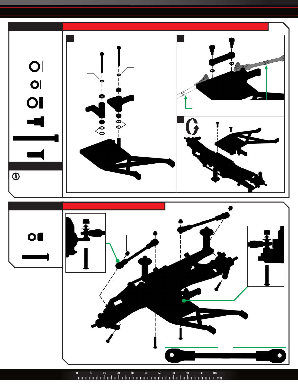
D. FRONT MODULE ASSEMBLY
FRONT SUSPENSION BAG
Servo Saver
Steering Link
M3x0.5 NL
3x14mm BCS (2)
D10. Install steering link and servo saver to bellcrank
3x14mm
BCS
Steering
Link
M3x0.5 NL
Servo
Saver
3x14mm
BCS
62.5mm
FRONT SUSPENSION BAG
Front Bumper
4x12mm CCS (4)
Steering Link
D11. Install front bumper onto front bulkhead
4x12mm
CCS
4x12mm
CCS
Front
Bumper
SLASH KIT • 21
Page 22

D. FRONT MODULE ASSEMBLY
FRONT SUSPENSION BAG
3x15mm BCS (4)
Note: These screws
may be included in
the CHASSIS BAG
D12. Install front shocks
3x15mm
BCS
3x15mm
BCS
3x15mm
BCS
3x15mm
BCS
Completed front module assembly
Install into Position 1
for best off-road
1 2
performance.
Check your assembly carefully.
22 • SLASH KIT
Page 23

E. CHASSIS ASSEMBLY
CHASSIS BAG
Slash Chassis
3x8mm FCS (4)
3x15mm CS (2)
ELECTRONICS BAG
Steering Servo
XL-5 Electronic
Speed Control (ESC)
ACCESSORY
Option Part
2075 Digital
High-Torque Servo
2275R Digital
High-Speed Servo
2250 Coreless Servo
2255 Brushless Servo
Option Part
3350R Velineon VXL-3s
Brushless Power System
E1. Install steering servo into chassis E2. Install electronic speed control onto chassis
Slash
Chassis
Wires face
front
3x8mm
FCS
Steering
Servo
3x15mm
CS
XL-5 Electronic
Speed Control
Chassis
Slash
CHASSIS BAG
Lower Receiver Box
Lower Receiver Box Foam
ELECTRONICS BAG
TQ Receiver
Receiver Foam Tape
ACCESSORY
Option Part
6533 TQi 2.4GHz
5Ch Micro Receiver
E3. Install receiver into lower receiver box
Lower Receiver
Box Foam
Lower
Receiver
Box
Tip: Route the antenna
wire out of the lower
receiver box before
attaching the receiver
Route antenna wire through antenna post
TQ Receiver
Receiver
Foam Tape
SLASH KIT • 23
Page 24

E. CHASSIS ASSEMBLY
CHASSIS BAG
3x6mm BCS (2)
E4. Install the lower receiver box E5. Install wires into the receiver box and plug the wires into the receiver
3x6mm
BCS
Steering ServoSteering Servo
CH1CH1
Route the servo wire
through the chassis
Electronic Electronic
Speed ControlSpeed Control
CH2CH2
Route wires through
the lower receiver box
CH3 Not Used
CH2 Electronic Speed Control
CH1 Not Used
CH1 Steering Servo
Bundle excess wires
into the receiver box
CHASSIS BAG
Antenna Tip
Antenna Tube
Antenna Crimp Nut
TOOLS BAG
Antenna Nut Wrench
E6. Slide the antenna wire into the antenna tube and install into the post on the lower receiver box
1.
Antenna
Tube
Antenna
Post
Take care not to crimp
the antenna wire when
inserting the antenna tube
2.
Slide the crimp nut
over the antenna tube
onto the post.
Antenna
Crimp Nut
3.
Use the supplied tool
to tighten the crimp
nut on the post.
Do not overtighten or crush the antenna wire.
Do not kink or cut the black wire, do not bend
or cut the metal tip, and do not bend or cut the
white wire at the end of the metal tip. Do not
shorten the antenna tube.
4.
antenna tip.
Antenna
Tip
Install
24 • SLASH KIT
Page 25

E. CHASSIS ASSEMBLY
CHASSIS BAG
Receiver Box Cover
O-Ring Seal
3x8mm BCS (2)
Receiver Wire Clamp
Upper Receiver Box Foam
2.5x8mm CS (2)
ELECTRONICS BAG
Silicone Grease
E7. Waterproof and seal the receiver box
1.
Receiver Box
3x8mm
BCS
O-Ring
Seal
Cover
3x8mm
BCS
2. 3.
Receiver
Wire Clamp
4.
Upper Receiver
Box Foam
2.5x8mm CS
2.5x8mm CS
Apply small
bead of grease
CHASSIS BAG
Battery Hold Down Mount
Battery Hold Down
3x15mm CCS (2)
Battery Post
Angled Body Clip
TOOLS BAG
4-Way Wrench
E8. Install battery hold down
3x15mm
CCS
Battery Hold
Down Mount
Take care not to crimp the wires during installation
Use included
4-way wrench
for battery post
installation
Battery
Post
Battery Hold
Down
Angled
Body Clip
SLASH KIT • 25
Page 26

E. CHASSIS ASSEMBLY
CHASSIS BAG
Nerf Bar (2)
3x8mm BCS (4)
E9. Install nerf bars onto the chassis
3x8mm
BCS
Nerf Bar
3x8mm
BCS
3x8mm
BCS
Nerf Bar
3x8mm
BCS
Completed chassis assembly
Check your assembly carefully.
26 • SLASH KIT
Page 27

F. SUSPENSION INSTALLATION
CHASSIS BAG
3x12mm BCS (4)
F1. Attach the rear module to the chassis
Route ESC wires through the shock tower and
connect to the motor. Red to red / black to black.
3x12mm
BCS
3x12mm
BCS
Rear
Module
CHASSIS BAG
Front Bumper Mount
3x12mm BCS (2)
3x15mm BCS (2)
4x12mm BCS (4)
4x14mm BCS
F2. Attach the front module to the chassis
1.
Ensure the steering bellcrank screw heads are
seated into the bosses on the chassis bottom.
4x12mm
BCS
Front
Module
3x12mm
BCS
2.
Front
Bumper
Mount
4x12mm
BCS
4x14mm BCS
3x15mm BCS
3x15mm
BCS
SLASH KIT • 27
Page 28

F. SUSPENSION INSTALLATION
CHASSIS BAG
3x10mm BCS
Completed installation
F3. Center the steering servo F4. Install the servo horn onto the servo
1 2
Turn transmitter on
(see Quick Start)
3
Turn on the model
(see Quick Start)
5
Unplug battery and turn transmitter o
4
Set Steering Trim to Zero
Plug charged battery
into ESC
(see Quick Start)
(see Quick Start)
3x10mm
BCS
Check your assembly carefully.
28 • SLASH KIT
Page 29

G. FINAL ASSEMBLY
WHEELS AND TIRE BAG
M4x0.7 NL (4)
Assembled Front Tires
and Wheels (2)
Assembled Rear Tires
and Wheels (2)
Kit assembly complete
G1. Install tires on front and rear axles
x4
Note the location marked on the
inside of the wheel when installing.
M4x0.7 NL
SLASH KIT • 29
Page 30

APPENDIX
Painting the Body
Buying Paint
The body supplied with your model is molded from
lightweight and durable clear polycarbonate. It should
be painted on the underside so that the color will not
be scratched off while running. The best way to paint
the body is by using thinned paints sprayed through an
airbrush or spray gun. If you do not have these tools, the
next best way is using spray can paints. Whatever paint
you use, be sure that it is made for painting Lexan® or
polycarbonate. Other types of paints and solvents can
attack the body material and cause it to appear foggy.
Preparing the Body
The body must be washed thoroughly with dish soap and
water to remove any grease or oil (i.e., fingerprints), which
may keep the paint from adhering to it. Dry the body
completely with a soft, lint-free cloth. Use the supplied
masks to mask the windows and any stripes or custom
effects on the truck body. Special tape made for striping is
also available from automotive paint supply stores and will
provide sharper edges. For easy, custom-colored striping,
automotive pin-striping tape can be applied to the inside
of the body and painted over. Be sure that all of your tape
and masks are fully pressed down (burnished) so that the
paint will not run or bleed underneath. Usually, the darker
colors are painted first, followed by the lighter colors. If
your paint scheme would be easier to mask by covering
the dark areas and spraying them last, be sure the lighter
colors are opaque enough to prevent the darker color
from showing through. Lighter colors can be backed with
silver to help make them opaque.
Note: Please read this entire section and plan your paint job before beginning.
Spraying the Body
Read the directions on your bottle or can of paint
and shake, mix, or thin the paint, as required. It is very
important to avoid breathing the paint vapors, as they
are extremely harmful. Spray the paint outdoors in
well-ventilated areas only. Apply the paint to the body
sparingly and in light coats. Be patient! Let the paint
dry fully in between coats. This will prevent accidentally
smearing wet paint. Take extra care when masks are being
removed. After the body is completely painted, remove
the peel coat from the outside of the body.
Decals
You are now ready to apply the decals. The decals have
been die-cut for your convenience. Test the position
of the decals before applying them to the body. Once
the decals have been applied, they cannot be removed
without damaging them. You can spray the body with
window cleaner before applying the decals. This will allow
you to re-position them. Once positioned, squeegee the
cleaner from under the decal. The decal will adhere when
it dries. If you have air bubbles in the decals, puncture the
center of each bubble with a sharp pin and push the air
out. If you have creases along the outer edges of a decal
(especially when applied to curved surfaces), use a hobby
knife to cut along the top of the crease and overlap the
edges.
30 • SLASH KIT
Page 31

APPENDIX
MAIN DOCUMENTS BAG
Body Clip (4)
Appendix 1: Body installation
SLASH KIT • 31
Page 32

QUICK START GUIDE
The following guide is an overview of the procedures for getting your
model running. The complete manual for your model can be viewed
and downloaded by following the link on the cover of this manual or
by scanning the QR code. Please read this entire manual for complete
instructions on the proper use and maintenance of your model.
Read the Safety Precautions
For your own safety, understand where carelessness and misuse could
lead to personal injury and product damage.
Prepare Your Model
Selecting a charger and batteries for your model
Your model does not include a battery or charger. The speed control in
the model is compatible with both LiPo and NiMH batteries. One NiMH
or 2s LiPo battery equipped with a Traxxas High Current connector is
required. Traxxas Power Cell iD batteries are strongly recommended
for maximum performance and safer charging. The following chart lists
available Power Cell batteries for your model:
LiPo Batteries with iD
2843X 5800mAh 7.4V 2-Cell 25C LiPo Battery
2869X 7600mAh 7.4V 2-Cell 25C LiPo Battery
NiMH Batteries with iD
2923X Battery, Power Cell, 3000mAh (NiMH, 7-C at, 8.4V)
2940X Battery, Series 3 Power Cell, 3300mAh (NiMH, 7-C at, 8.4V)
2950X Battery, Series 4 Power Cell, 4200mAh (NiMH, 7-C at, 8.4V)
WARNING: FIRE HAZARD!
Users of Lithium Polymer (LiPo) batteries must read the
Warnings and Precautions beginning on page 2. You
MUST use a LiPo charger for LiPo batteries or battery damage
with the potential for fire will result.
Install the battery pack in the model
Place the battery in the tray. Insert the
hold-down into the chassis as shown.
Secure by placing the clip into the post.
Compatible batteries:
• 6-7 cell NiMH • 2-cell LiPo
ATTENTION: USERS
OF LiPo BATTERIES
Activate Low-Voltage Detection when
using LiPo batteries. Refer to the EZ-Set
Tips card attached to your model, or see
the Electronic Speed Control Adjustments section of this guide.
Turning on Your Model
Turn on the transmitter
Always turn the transmitter on first, before turning on the model. The
transmitter’s LED will glow green.
Plug the battery into the speed control
Align the + and – markings. Make certain the battery plug is
completely inserted.
Turn on the model
Press and release the EZ-Set button on the speed control. The speed
control’s LED will glow.
11
Always turn your
transmitter on rst.
22
Plug in the battery.
33
Turn on the model.
Make certain you choose the correct type of charger for the batteries you
select. Traxxas recommends you choose a genuine Traxxas EZ-Peak iD
charger for safer charging and maximum battery life and performance.
Charger Part No.
EZ-Peak Plus,
4 amps
EZ-Peak Live,
12 amps
EZ-Peak Dual,
8 amps
EZ-Peak Live
Dual, 26+ amps
2970 YES YES YES 3s
2971 YES YES YES 4s
2972 YES YES YES 3s
2973 YES YES YES 4s
NiMH
Compatible
LiPo
Compatible
Battery iDMax.
Cells
Install batteries in the transmitter
The transmitter requires 4 AA alkaline or rechargeable batteries.
Before Operating Your Model
Check servo operation
Confirm the model’s wheels turn right and left when the transmitter
steering wheel is turned right and left. The front wheels should be pointing
straight ahead. If they are turned slightly, slowly adjust the steering trim
control on the transmitter until they are pointing straight ahead.
Range test the radio system
With a friend’s help, check servo operation at the farthest distance you
plan to drive the model and confirm that there is no radio interference.
Operating Your Model
T
U
R
N
R
I
G
H
T
U
R
N
L
E
F
T
T
Neutral
Brake/Reverse
32 • SLASH KIT
Forward
Note: After stopping the model, return the transmitter’s trigger to
neutral and push up again to activate reverse throttle.
Page 33

QUICK START GUIDE
Avoid running your model in tall grass or soft sand. These will strain
the power system and could damage the motor. If the model becomes
stuck, do not apply throttle. Free the model before operating it.
The TQ 2.4GHz transmitter has a directional antenna. For maximum range,
hold the transmitter upright and pointed in the direction of the model.
Pointing the transmitter away from the model will reduce radio range.
Transmitter Adjustments
Steering Trim
Slowly turn the steering trim knob to precisely set the steering
neutral point. To adjust, drive the vehicle forward slowly
while “steering” with the trim knob until the vehicle travels in
a straight line with no steering input.
Electronic Speed Control Adjustments
ATTENTION: IF USING A LiPo BATTERY
To prevent over-discharging of LiPo batteries, Low-Voltage
Detection must be switched on. To check the status of your model, turn
it on. If the speed control’s LED is green, Low-Voltage Detection is
already activated. If the LED is red, Low-Voltage Detection is not active.
Follow these steps to turn on Low-Voltage Detection:
1. Turn the model on. Make sure the LED on the
speed control is on and red.
A
2. Press and hold the EZ-Set button for ten seconds.
The LED will turn off and then light green, and the
motor will beep twice. Release the button.
3. Low-Voltage Detection is now ACTIVATED.
Red LED: Hold 10 seconds
B
LiPo batteries are intended only for the most
advanced users that are educated on the risks
associated with LiPo battery use.
2 Beeps: LED shines green
To disable Low-Voltage Detection when using NiMH batteries, repeat the
steps above. The motor will beep three times and the LED will glow red.
WARNING: FIRE HAZARD!
Do not use LiPo batteries in this vehicle with
Low-Voltage Detection disabled.
Calibrating the Speed Control
The speed control is calibrated at the factory. If the LED on the speed
control is flashing green, then follow these steps to recalibrate it.
1. Connect a fully charged battery to the model.
2. Turn on the transmitter (with the throttle at neutral).
3. Press and hold the EZ-Set button (A).
A
The LED will first turn green and then
red. Release the EZ-Set button.
4. When the LED blinks RED ONCE, pull
the throttle trigger to the full throttle
Green then Red
B
position and hold it there (B).
5. When the LED blinks RED TWICE, push
the throttle trigger to the full reverse
and hold it there (C).
6.
When the LED blinks GREEN ONCE,
programming is complete. The LED will
Once Red
C
Twice Red
then shine green or red (depending on
Low-Voltage Detection setting).
Running in Wet Conditions
Your Traxxas model is designed with water-resistant features to protect
the electronics in the model (receiver, servos, electronic speed control).
Though highly water resistant, the model should not be treated as
though it is submersible or totally, 100% waterproof. Water resistance
applies only to the installed electronic components. Running in wet
conditions requires additional care and maintenance to prevent
corrosion and maintain proper function. Download the complete
manual for full precautions and maintenance requirements. Read
and understand all precautions before operating your model in wet
conditions. The complete manual for your model can be viewed and
downloaded by following the link on the cover of this manual or by
scanning the QR code. Please read this entire manual for complete
instructions on the proper use and maintenance of your model.
Gearing
Your model may include additional gears. These gears are for maximumspeed running on hard surfaces only. Using the high-speed gearing for
general driving and off-road driving may overheat the motor, speed
control, or battery. For full instructions on installing and using the highspeed gearing, download the complete manual. The complete manual
for your model can be viewed and downloaded by following the link
on the cover of this manual or by scanning the QR code. Please read
this entire manual for complete instructions on the proper use and
maintenance of your model.
Selecting a Throttle Mode: SPORT, RACE, or TRAINING
Connect a fully charged battery to the model and turn on your transmitter.
1.
2. With the model off, press and hold the EZ-Set button until the LED
turns solid green, then solid red, and then begins blinking red. It will
blink once, then twice, then three times, then repeat.
One blink = Sport Mode is the default setting. It allows full forward
and reverse throttle.
Two blinks = Race Mode removes reverse throttle in case your track
does not allow it.
Three blinks = Training Mode will slow the model down by 50% for
young or inexperienced drivers.
3. Release the EZ-Set button after the number of blinks for the mode you
wish to select. Note: If you missed the mode you wanted, keep the EZ-Set
button pressed down and the blink cycle will repeat.
4. The LED will blink and then turn solid green (Low-Voltage Detection
ACTIVE) or red (Low-Voltage Detection DISABLED). The model is now
ready to drive.
After You Run Your Model
Turn the model o
Press and release the EZ-Set button on the speed control.
The speed control’s LED will go out.
Unplug the battery and remove it from the model
Do not store the model with the battery installed.
Turn the transmitter o
Always turn the transmitter off last, after the model has been
turned off.
11
Turn o the model.
22
Unplug the battery.
33
Always turn your
transmitter o last.
SLASH KIT • 33
Page 34

NOTES
34 • SLASH KIT
Page 35

NOTES
SLASH KIT • 35
Page 36

ASSEMBLY MANUAL
200514 KC2850-R03
MODEL 58014-4
6250 TRAXXAS WAY, McKINNEY, TEXAS 75070
1-888-TRAXXAS
Entire contents ©2020 Traxxas. No part of this manual may be reproduced or distributed in print or electronic media
without the express written permission of Traxxas. Specications are subject to change without notice.
 Loading...