

Page 1
Quality Refrigeration
OWNER’S MANUAL
Instructions for the installation, operation
and maintenance of Traulsen:
TS Series Pizza/Salad/Sandwich Prep Tables
TS048HT, TS066HT, TS072HT & TS090HT
This Traulsen unit is built to our highest quality standards. We build our refrigerators this way as a matter of pride. This philosophy has made Traulsen the
leader in commercial refrigeration since 1938. We thank you for your choice and confidence in Traulsen equipment and we know you will receive many years
of utility from this equipment.
All Traulsen units are placed on a permanent record file with the service department. In the event of any future questions you may have, please refer to the model
and serial number found on the name tag affixed to the unit. Should you need service, call us on our toll free number, 800-825-8220 between 7:30 am - 4:30
pm CST, Monday thru Friday. You may also log onto www.traulsen.com for further information. It is our pleasure to help and assist you in every possible way.
INSTALLER
COMPLETE THE FOLLOWING INFORMATION PRIOR TO UNIT INSTALLATION
INITIAL START DATE: SERIAL NO.
MODEL TYPE:
COMPANY/INDIVIDUAL NAME:
INSTALLER:
FORM NUMBER TR35921 REV. 11/10 P/N 375-60308-00
Page 2
TABLE OF CONTENTS
I. THE SERIAL TAG Page 1
II. RECEIPT INSPECTION Page 2
III. OPERTIONAL GUIDELINES Page 2
IV. INSTALLATION
a-Location Page 2
b-Packaging Page 2
c-Installing/Adjusting Legs orCasters Page 2
d-Doors Page 2
e-Installing Optional Drawers Page 2
f-Cord & Plug Page 2
g-Power Supply Page 3
V. DAILY OPERATION
a-Pans Page 3
b-Setting Up The Rail Page 3
c-Closing Down The Rail At Night Page 3
d-Defrost Page 3
VI. CARE & MAINTENANCE
a-Cleaning The Condenser/Filter Page 4
b-Replacing The Gaskets Page 4
c-Cleaning The Cabinet Surfaces Page 4
d-Cleaning The Rail Area Page 4
VII. MICROPROCESSOR CONTROL
a-Control Features Page 5
b-Alarm Explanations Page 6
c-Control Panel Diagram Page 7
d-Notes To The User Page 7
e-Enter The Service Access Page 7
f-Customer/Service Parameters Page 7
g-Adjusting Thermostat Set Point Page 8
h-Adjusting Thermostat Set Point Differential Page 8
i-Changing The Temperature Scale Page 8
j-Setting The 24-Hour Clock Page 8
k-Setting The Date Page 9
l-Setting Daylight Savings Time Page 9
m-Starting A Manual Defrost Cycle Page 10
n-Setting Defrost Lockouts Page 10
o-Adjusting The Room Temperature Offset Page 11
p-Viewing Sensor Temperatures Page 11
VIII. WIRING DIAGRAM Page 12
IX. TROUBLE SHOOTING GUIDE Page 13
X. SERVICE ASSISTANCE
a-Service Information Page 14
b-Service Support Information Page 14
c-Warranty Registration Page 14
XI. WARRANTIES Page 15
XII. SERVICE PARTS LIST Page 16
I. THE SERIAL TAG
I. a - SERIAL TAG:
The serial tag is a permanently affixed label on which is recorded vital
electrical and refrigeration data about your Traulsen product, as well
as the model and serial number. This tag is located in the right interior
compartment on all standard TS Series models.
READING THE SERIAL TAG
• Serial = The permanent ID# of your Traulsen unit
• Model = The model # of your Traulsen unit
• Volts = Voltage
• Hz = Cycle
• PH = Phase
• Total Current = Maximum amp draw
• Minimum Circuit = Minimum circuit ampacity
• Lights = Light wattage
• Heaters = Heater amperage (Hot Food units only)
• Refrigerant = Refrigerant type used and refrigerant charge
• Design Pressure = High & low side operating pressures
• Agency Labels = Designates agency listings
FORT WORTH, TX.
SERIAL MODEL
VOLTS Hz PH
TOTAL CURRENT AMPS
MINIMUM CIRCUIT AMPS
MAXIMUM OVERCURRENT PROTECTION AMPS
LIGHTS WATTS
HEATERS AMPS
REFRIGERANT TYPE OZ
DESIGN PRESSURE HIGH LOW
REFRIGERANT TYPE OZ
DESIGN PRESSURE HIGH LOW
370-60294-00 REV (A)
COMMERCIAL REFRIGERATION
-1-
Page 3

II. RECEIPT INSPECTION
IV. INSTALLATION (CONTINUED)
II. a - RECEIPT INSPECTION:
All Traulsen products are factory tested for performance and are free
from defects when shipped. The utmost care has been taken in crating
this product to protect against damage in transit.
You should carefully inspect your unit for damage during delivery. If
damage is detected, you should save all the crating materials and
make note on the carrier’s Bill Of Lading describing the damage. A
freight claim should be filed immediately. If damage is subsequently
noted during or immediately after installation, contact our customer
care team to le a freight claim. There is a fteen (15) day limit to le
freight damage with the carrier. Under no condition may a damaged
unit be returned to Traulsen without first obtaining written permission
(return authorization). You may contact Hobart/Traulsen customer care
at 800-333-7447 to request a return or file a claim.
III. OPERATIONAL GUIDELINES
III. a - OPERATIONAL GUIDELINES:
Follow these simple guidelines for proper TS Series Operation.
1. Keep the condenser clean. Don’t obstruct airflow.
2. Use up to 6” deep stainless steel or aluminum pans.
3. All pan spaces should be filled any time the unit is running, even if
some pans are empty.
4. Keep the room temperature at 860F (300C) or less.
5. Do not allow air drafts (such as heat, A/C or ventilation) to blow on
or over the rail area. This will disrupt the air blanket over the product
area, resulting in poor holding temperatures.
6. Rail covers should be closed over the rail as much as possible.
7. Product should be loaded into the rail at a maximum temperature of
360F. The TS Series unit was not designed to chill warm product, but
to hold refrigerated product at a safe temperature.
8. Keep area around the evaporator fans clear.
IV. b - PACKAGING (continued):
To remove the wooden pallet, first if at all possible, we suggest that the cabinet
remain bolted to the pallet during all transportation to the point of final installation.
The bolts can then be removed with a 1/2” socket wrench. Avoid laying the unit
on its front, side or back for removal of the pallet.
NOTE: Traulsen does not recommend laying the unit on its front, side or
back. If you must, please allow the unit to remain in an upright position
for 24 hours before plugging it in so that the compressor oils and refriger-
ant may settle.
IV. c - INSTALLING/ADJUSTING LEGS OR CASTERS:
To install legs or casters, slide leg or caster into the caster channel from the side
of the unit without the refrigeration system.
To adjust the legs or casters, loosen the two bolts and move leg or caster to desired
location, spacing between leg or caster not to exceed 48 inches. Leg or caster on
each end of the unit can not exceed 8 inches from the end of the cabinet.
NOTE: Traulsen recommends to position legs or casters under the mullion
when possible.
IV. INSTALLATION
IV. a - LOCATION:
Select a proper location for your unit, away from extreme heat or cold.
Allow enough clearance between the unit and the side wall in order to
make use of the door stay open feature at 1200 (self-closing feature
operates up to 900). The door(s) must be able to open a minimum of
900 in order to make use of the maximum clear door width.
IV. b - PACKAGING:
Your Traulsen unit is shipped from the factory bolted to a sturdy wooden
pallet in stretch wrapped material and wood crate.
Most exterior stainless steel surfaces have a protective vinyl covering to
prevent scratching during manufacturing, shipping and installation.
After the unit is installed in place of application peel, remove and discard
the covering from all surfaces.
IV. d - DOORS:
Your Traulsen TS Series model door(s) are eld re-hingeable. If re-hinging is
required, please contact our in-house service department at 800-825-8220 for
re-hinging instructions.
IV. e - INSTALLING OPTIONAL DRAWERS:
Doors are supplied standard on all TS Series models. However, we have engineered
our refrigerator models with a drop-in feature that allows you to easily convert
door(s) into two 6” deep drawers or three 4” deep drawers.
The door(s) on the refrigerator models can easily be converted to drawers in the
field. To begin the process, open the door to its maximum position. Support the
non-hinged end of the door so minimum movement occurs. When the bolts from
the lower hinge plate are removed, remove the lower hinge plate and then the door
from the top hinge bracket plate and then the door from the top hinge bracket.
The hinge plate pin and plastic bushing will remain in the top hinge plate.
NOTE: The lower hinge plate is under spring tension.
-2-
Page 4
IV. INSTALLATION (continued)
IV. INSTALLATION (continued)
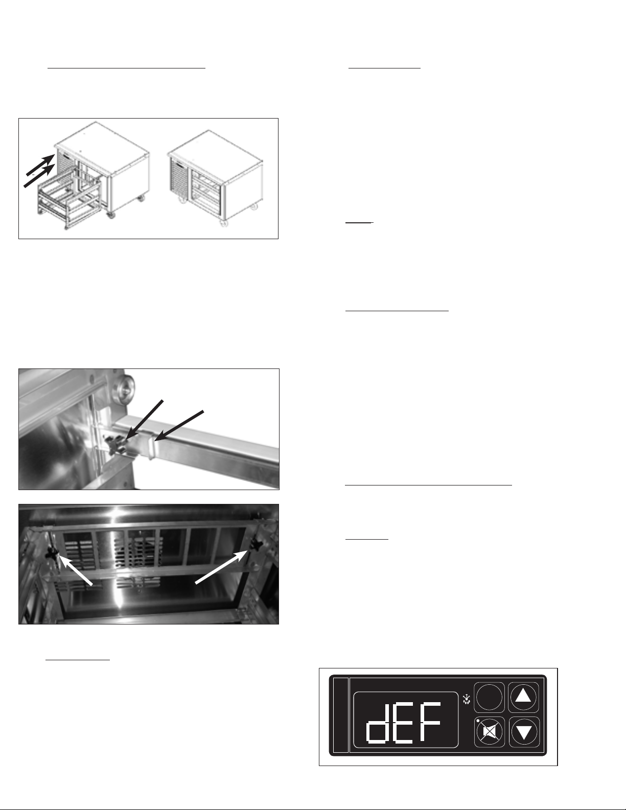
IV. e - INSTALLING OPTIONAL DRAWERS (continued):
Once the door(s) have been removed, Insert drawer frame as shown below.
NOTE: Undercounter model drawings shown below.
Once the drawer frame has been inserted, the drawer frame module can be
installed by tighting the black front and back clamping knobs (2 of each) located
on the cross rail locks and liner locks. Slide the front cross rail locks towards the
center of the drawer frame module and allow the liner locks to drop down from
the top of the liner. Insert the door frame module push towards the back of the
unit. The entire frame assembly is now installed and ready for use.
NOTE: Repeat process for multiple drawer inserts.
IV. g - POWER SUPPLY:
The supply voltage should be checked prior to connection to be certain
that proper voltage for the cabinet wiring is available (refer to the serial
tag to determine correct unit voltage, see page 1). Make connections in
accordance with local electrical codes. Use qualified electricians.
Use of a separate, dedicated circuit is required. Size wiring to handle
indicated load and provide necessary over current protector in circuit
(see amperage requirements on the unit’s serial tag).
V. DAILY OPERATION
V. a - PANS:
Standard TS Series models are designed to operate with full, half or third
size pans without the use of adapter bars. Other fractional size pans can
be used with optional adapter bars available from Traulsen. 4” deep pans
provide the best temperature performance in the rail. Both 2” & 6” deep
pans will also perform to NSF7 temperature requirements.
V. b - SETTING UP THE RAIL:
Install pans in all pan spaces in the rail. Rest each pan evenly on the
front and back support ledges. Do not use uneven or bent pans, as
these will allow circulating cold air to escape.
Front Clamping Knobs
Front Cross Rail Locks
Back Clamping
Knobs
IV. f - CORD & PLUG:
All self-contained models are shipped standard with a NEMA 5-15P plug and 9
foot cord . Select only a dedicated electrical outlet for power source.
NOTE: Do not under any circumstances, cut or remove the round grounding
prong from the plug, or use an extension cord.
Allow the unit to reach operating temperature before loading any food
product. Load only refrigerated product at 360F or below.
All pan spaces should be lled, even if some pans are empty (even
during nighttime storage).
When not in constant use, the TS Series rail covers should be kept
closed over the pans.
V. c - CLOSING DOWN THE RAIL AT NIGHT:
Food product may be stored in the rail overnight if needed. Cover the entire rail with plastic wrap prior to closing the rail covers over the pans.
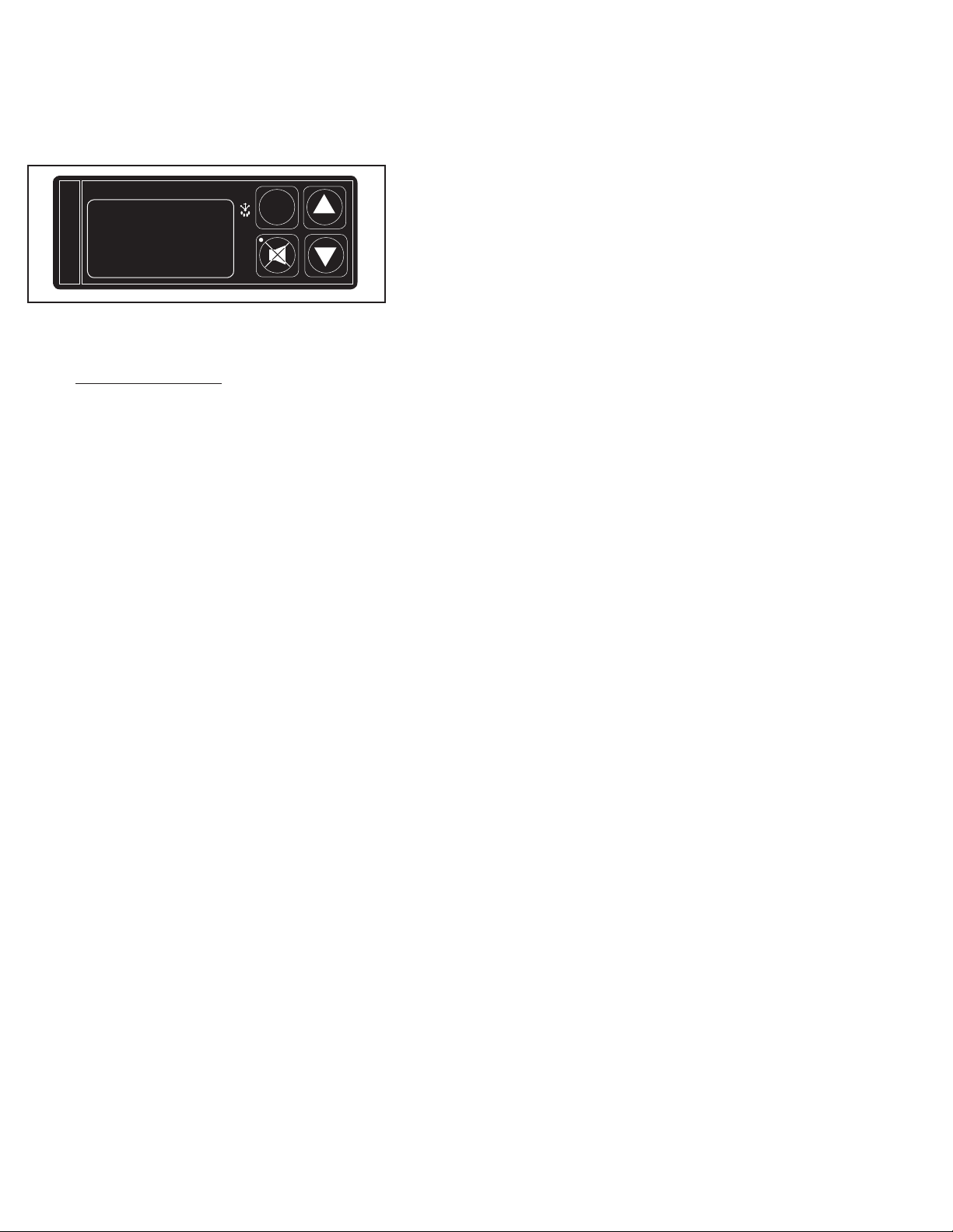
V. d - DEFROST:
The Traulsen refrigerated Prep Table is equipped with an automatic hot
gas defrost system which clears the evaporator coil of any accumulated
frost. Frost is accumulates on the evaporator coil during the normal
refrigeration or cool cycle. The defrost cycle occurs automatically every three hours and is indicated by the illumination of the green snow
flack and the letters “DEF” displayed on the screen of the Intela-Traul
control. The defrost cycle should last for approximately ten to twenty
minutes. At the completion of the defrost cycle the cabinet will resume
normal refrigeration operation with the compressor cycling ON and OFF
to maintain cabinet and rail temperature.
INTELA-TRAUL
°F °C
FREEZER
SET
-3-
Page 5
VI. CARE & MAINTENANCE (continued)VI. CARE & MAINTENANCE
DOOR GASKET
INSIDE DOOR PANEL
OUTSIDE DOOR PANEL
GASKET RETAINER
VI. a - CLEANING THE CONDENSER/FILTER:
The most important thing you can do to insure a long, reliable service
life for your Traulsen is to regularly clean the condenser coil and or
filter if provided.
The patented microprocessor control will notify you through a “CLN-FIL”
message when the condensing temperature of the refrigerator reaches
140 degrees F or greater. If the condensing temperature reaches 160
degrees F the compressor will automatically turn off . When the temperature drops below 140 degrees F the compressor will restart and when
the temperature drops below 120 degrees F the alarm will reset.
WARNING: DISCONNECT ELECTRICAL POWER SUPPLY BEFORE
CLEANING ANY PARTS OF THE UNIT.
To clean the condenser/filter, first disconnect electrical power to the
cabinet and remove the front hinged louver assembly. Proceed to
vacuum or brush any dirt, lint or dust from the finned condenser coil/
filter, the compressor and other cooling system parts. If significant dirt
is clogging the condenser fins or filter, use compressed air to blow this
clear. To replace the louver assembly reverse the process.
VI. b - REPLACING THE GASKETS:
To remove the gasket to be replaced, grasp it firmly by one corner and
pull it out. Before attempting to install a new gasket, both the unit and
the gasket itself must be at room temperature. Insert the four corners
rst by using a rubber mallet (or hammer with a block of wood). After
the corners are properly inserted, work your way towards the center from
both ends by gently hitting with a mallet until the gasket is completely
seated in place (see gure for proper gasket placement).
VI. c - CLEANING THE CABINET SURFACES (continued):
Care should also be taken to avoid splashing the unit with water, containing chlorinated cleansers, when mopping the floor around the unit. For stubborn odor or
spills, use baking soda and water (mixed to a 1 tbsp baking soda to 1 pint water
ratio). A stainless steel polish is recommended for shining of unit.
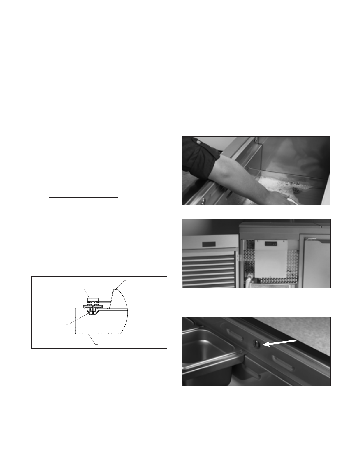
VI. d - CLEANING THE RAIL AREA :
WARNING: DISCONNECT ELECTRICAL POWER SUPPLY BEFORE CLEANING
ANY PARTS OF THE UNIT.
Temperature rail is equipped with drain and flush valve. Up to 5 gallons of water
can be used to clean rail compartment.
NOTE: The gasket may appear too large, but if it is installed as
indicated above it will slip into place.
VI. c - CLEANING THE CABINET SURFACES:
WARNING: DISCONNECT ELECTRICAL POWER SUPPLY BEFORE
CLEANING ANY PARTS OF THE UNIT.
Exterior stainless steel should be cleaned with warm water, mild soap
and a soft cloth. Apply with a dampened cloth and wipe in the direction of the metal grain. Avoid the use of strong detergents and gritty,
abrasive cleaners as they may tend to mar and scratch the surface.
Do NOT use cleansers containing chlorine, such as bleach, this may
promote corrosion of the stainless steel.
For excessive spills the front and rear air baffle in the rail are removable by unscrewing the thumb screws.
Air baffles can be cleaned in a sink using caution not to loose fasteners.
NOTE: Use caution in avoiding getting excessive water down in cabinet
ducts with outer air ducts removed.
-4-
Page 6
VII. PATENTED MICROPROCESSOR CONTROL
Your new refrigerator cabinet is equipped with a state-of-the-art patented microprocessor control, which precisely regulates operation and provides alarms
when problems occur. It is supplied from the factory completely ready for use and requires no adjustments, but without the audible alarms activated. See
pages 5 thru 11 for more information.
INTELA-TRAUL
°F °C
FREEZER
PATENTED MICROPROCESSOR CONTROL
VII. a - CONTROL FEATURES:
1- Internal Time Clock
• Eliminates external defrost time clock.
• Defrost cycle can be quickly adjusted to suit individual location and use.
• Must be set at power-up. (See page 8, “Setting the 24-Hour Clock”)
• Will automatically update for Daylight Savings Time.
SET
2- Water Resistant Housing
The face of the control is water resistant to provide for protection during cleaning.
3- Parameter/Service Levels
• See “Customer / Service Parameters” on Page 7.
4- Defrost Lockouts
See “Setting Defrost Lockouts” on page 10.
Customers can set up to 4 different defrost lockout periods. The lockout prevents the unit from going into a defrost cycle during peak kitchen use.
Note: The 24-hour clock must be set for this feature to operate correctly.
5- Communication Ability
A NAFEM Data Protocol (NDP) compliant RS-485 serial communications port is available to interface with data collection software (by others). All micropro-
cessor control equipped models are capable of communicating within a NAFEM Data Protocol network if provided with an optional Gateway Hub (available
from Traulsen). The actual communications software is available from a number of third party software vendors.
6- Alarms (See the following pages for explanations)
• High Cabinet Air Temperature
• Low Cabinet Air Temperature
• Loss Of Power
• Sensor Failure
• Clean Condenser
7- Display Features
• 3-Digit LED Display
• Defrost in Progress Icon
• Fahrenheit or Celsius Temperature Scale In Use
-5-
Page 7
VII. PATENTED MICROPROCESSOR CONTROL (continued)
VII. b - ALARM EXPLANATIONS:
Explanation of alarms assume the audible alarm style is set at a 3-second burst or a continuous audible alarm. References to the audible alarm do not
apply if the audible alarm style is set to OFF.
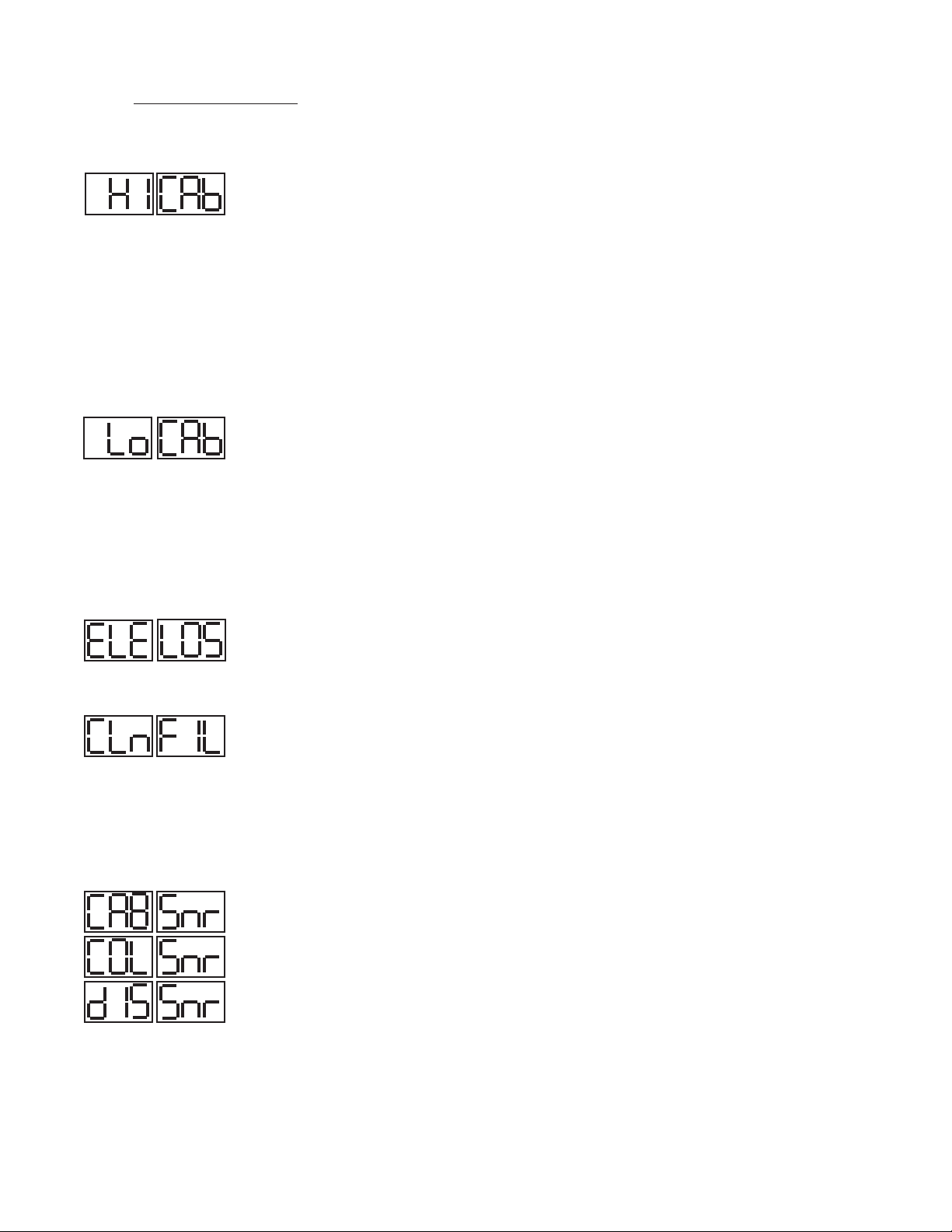
High Cabinet Air Temperature
The audible alarm will sound and the display will read HI CAb when the temperature inside the cabinet rises above a pre-programmed limit. The limit
is determined by the type of unit being operated (i.e.: refrigerator/freezer). To turn off the audible alarm, press the alarm cancel button. The visual alarm text
will continue to display until the cabinet air temperature falls below the limit. If the temperature does not fall below the limit within 5 minutes, the audible
alarm* will sound again and an additional Call Service message will display.
POSSIBLE CAUSES:
• Doors open for extended periods of time.
• Large amounts of hot product placed inside the cabinet.
• Condenser coil dirty.
• Cooling Compressor Failure. Call Service.
• Refrigeration Problems.
Low Cabinet Air Temperature
The audible alarm will sound and the display will read Lo Cab when the temperature inside the cabinet falls below a pre-programmed limit. The limit is
determined by the type of unit being operated (i.e.: refrigerator/ freezer). To turn off the audible alarm, press the alarm cancel button. The visual alarm text
will continue to display until the cabinet air temperature rises above the limit. If the temperature does not rise above the limit within 5 minutes, the audible
alarm will sound again and an additional Call Service message will display.
POSSIBLE CAUSES:
• No product in unit.
• Failed sensors.
• Stuck Evaporator Relay.
Loss Of Power
The audible alarm will sound and the display will read ELE LOS, when the unit regains power after an outage. To turn off the audible alarm and/or clear the
visual text, press the alarm cancel button.
Condenser Clean
The audible alarm will sound and the display will read “CLean FiLter” when discharge temperatures exceeds 140 degrees. As the load on the condenser
decreases, the alarm will turn off by itself. As the temperature on the condenser continue to rise, the audible alarm will return until the problem has been
eliminated.
NOTE: If discharge temperature rises above 1600F the compressor & condenser fan motor will be switched off until the discharge temp falls
below 1400F.
Sensor Failures
The audible alarm will sound and the display will read CAB Snr, COL Snr or DIS Snr when that particular sensor has failed to operate. To turn off the audible
alarm, press the alarm cancel function of the sensor, the audible alarm will sound again in either 5 minutes or 24 hours.
Note: Test sensor in ice water.
-6-
Page 8
VII. PATENTED MICROPROCESSOR CONTROL (continued)
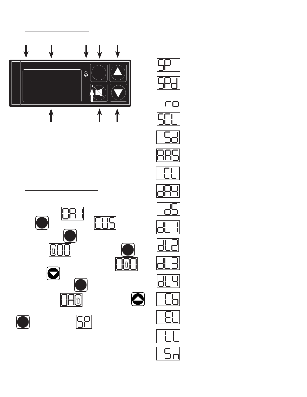
VII. c - CONTROL PANEL DIAGRAM:
0
F LED
°F °C
FREEZER
0
C LED
INTELA-TRAUL
LED DISPLAY DOWN BUTTON
SYBMBOL
RED ALARM LIGHT
ALARM CANCEL
DEFROST
SET
BUTTON
SET
BUTTON
UP BUTTON
VII. d - NOTES TO THE USER:
You only have 20-30 seconds between button pushes. If you take longer than 30
seconds, the controller will revert back to displaying the cabinet temperature. If
you enter the wrong security code, the controller will revert back to displaying the
cabinet temperature. You can exit the parameters at any time by waiting 20-30
seconds for the control to return to normal operation.
VII. f - CUSTOMER/SERVICE PARAMETERS:
Listed below are the available parameters in the order they appear,
using the down arrow key on the controller. You can use either the up
or down arrow keys to scroll through the options.
Thermostat Set Point
Thermostat Set Point Differential
Room Temperature Offset
Temperature Scale
Start Manual Defrost
Audible Alarm Style
Time (24-hour clock)
VII. e - ENTER THE CUSTOMER ACCESS:
Note: This is required to set any of the control parameters.
Use the security code 0, A, 1 and the following instructions: Press
the set button . The display will read Customer/Service
SET
Access. Press the set button . The display will show three zeros with
the left zero ashing . Press the set button . The
display will show three zeros with the center zero ashing Press
the down arrow key to sequence through F, E, d, C, b, A, 9, 8, 7,…
etc. When you reach “A” press set The display will show zero, A, zero
with the right zero ashing . Press the up arrow key to
sequence through 1, 2, 3, 4, 5, 6, 7, 8, 9, A, b,…etc. When you reach “1” press
set . The display will read Thermostat Set Point. You are
SET
SET
SET
SET
Date (month-day-year)
Daylight Savings
Defrost Lockout 1
Defrost Lockout 2
Defrost Lockout 3
Defrost Lockout 4
Cabinet Air Temperature
Evaporator Coil Temperature
now in the CUSTOMER/SERVICE PARAMETERS.
Liquid Line Temperature
Serial Number
-7-
Page 9

VII. PATENTED MICROPROCESSOR CONTROL (continued)
VII. g - ADJUSTING THE THERMOSTAT SET POINT:
This parameter sets the high point of the desired cabinet temperature range.
Typically, refrigerators will range from 36° F to 40° F (2.5° C to 3.3° C) for this
parameter setting. This parameter is preset at the factory and does not have to
be adjusted unless the customer chooses to do so.
Follow the instructions to enter the customer access code on page 7. When the
control display reads Thermostat Set Point. Press the set button
. Use the arrow keys to adjust the temperature to
SET
your desired setting. When the display shows the temperature you want press
the set button . The display will then read Thermostat Set
Point. You can use the up or down arrow keys to scroll to the next parameter
or wait 30 seconds for the control to return to normal opera-
tion.
SET
VII. h - ADJUSTING THE SET POINT DIFFERENTIAL:
This parameter sets the number of degrees the air temp will rise above set point
before the refrigeration system will cycle on. The set point differential is set at
1.5 which will allow the air temperature to rise 1.5 degrees above SP (set point)
setting before cycling refrigeration on. This parameter is preset at the factory and
does not have to be adjusted unless the customer chooses to do so.
Follow the instructions to enter the customer access code on page 7. When the
control displays Thermostat Set Point, press the down arrow key
VII. i - CHANGING THE TEMPERATURE SCALE:
The temperature scale determines if the temperature displayed will
be in degrees Fahrenheit or degrees Celsius.
Follow the instructions to enter the customer access code on page 7.
When the control displays Thermostat Set Point, press
the down arrow key until the control display reads
Temperature Scale. Press the set button .
The display will start with the current setting either for
degrees Fahrenheit or for degrees Celsius. Use the
arrow keys to toggle between the options. When
the display shows the scale you want press the set button .
The display will then read Temperature Scale. You
can use the up or down arrow keys to scroll to the
next parameter or wait 30 seconds for the control to return to normal
operation.
SET
SET
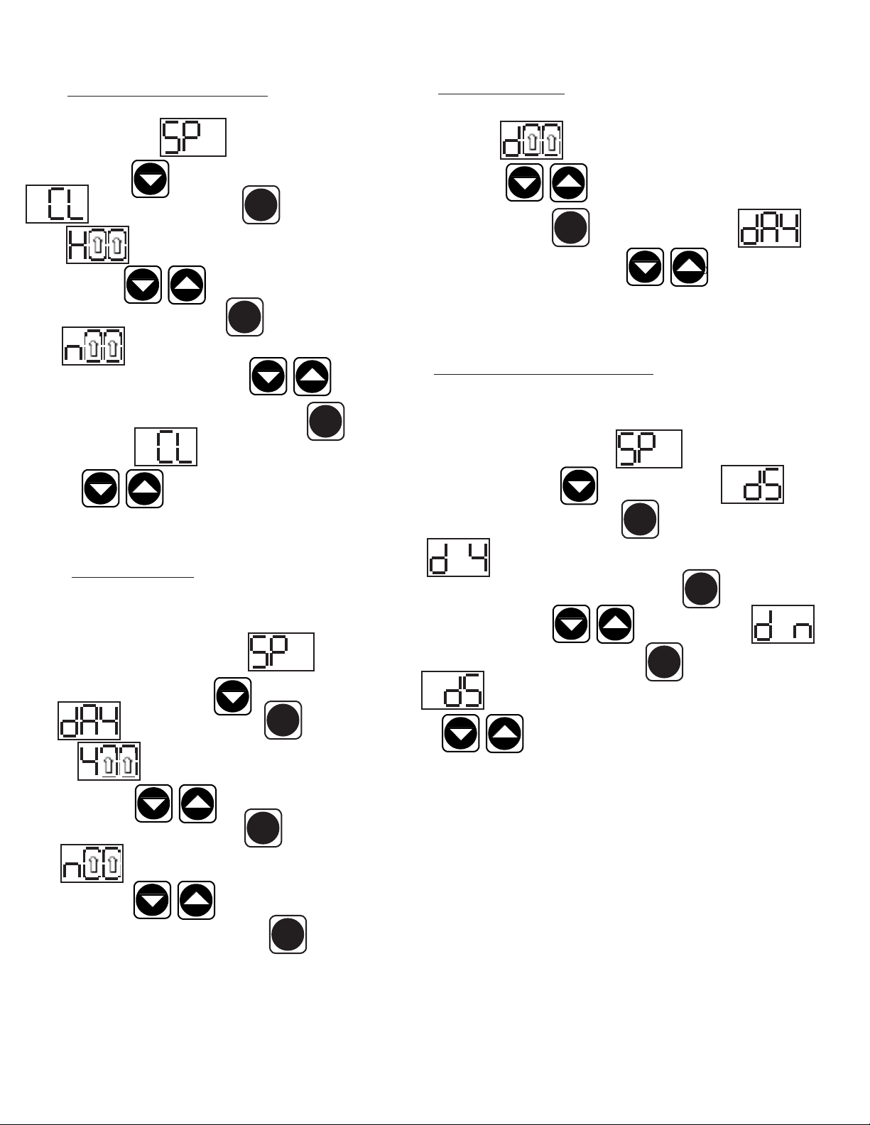
VII. j - SETTING THE 24-HOUR CLOCK:
The internal time clock must be set in order for the data storage memory
to correctly log events and to allow any defrost lockout to occur at the
correct time of day. If the clock is not set, the control assumes the time
is 12 a.m. at the time power is supplied to the unit. The hours on a
24-hour time clock read the following way:
until the control display reads Set Point Differential.
Press the set button . Use the arrow keys to adjust the
temperature to your desired setting. When the display shows the temperature you
want press the set button . The display will then read Set
Point Differential. You can use the up or down arrow keys to scroll to the next
parameter or wait 30 seconds for the control to return to normal
operation.
SET
SET
H01 = 1:00 a.m. H09 = 9:00 a.m. H17 = 5:00 p.m.
H02 = 2:00 a.m. H10 = 10:00 a.m. H18 = 6:00 p.m.
H03 = 3:00 a.m. H11 = 11:00 a.m. H19 = 7:00 p.m.
H04 = 4:00 a.m. H12 = 12:00 a.m. H20 = 8:00 p.m.
H05 = 5:00 a.m. H13 = 1:00 p.m. H21 = 9:00 p.m.
H06 = 6:00 a.m. H14 = 2:00 p.m. H22 = 10:00 p.m.
H07 = 7:00 a.m. H15 = 3:00 p.m. H23 = 11:00 p.m.
H08 = 8:00 a.m. H16 = 4:00 p.m. H24 = 12:00 a.m.
-8-
Page 10
VII. PATENTED MICROPROCESSOR CONTROL (continued)
VII. j - SETTING THE 24-HOUR CLOCK (continued):
Follow the instructions to enter the customer access code on page 7.
When the control displays Thermostat Set Point, press
the down arrow key until the control display reads
Clock. Press the set button . The display will
show Hours. The right two numbers will be flashing.
Use the arrow keys to set the hour. When the correct
hour is displayed, press the set button . The display will sh
ow Minutes. The right two numbers will be flash-
ing. Use the arrow keys to set the minutes . When
the correct minutes are displayed, press the set button . The
display will then read Clock. You can use the up or down
arrow keys to scroll to the next parameter, or wait 30
SET
SET
SET
VII. k - SETTING THE DATE (continued):
The display will show (day). The right two numbers will be ashing.
Press the arrow keys to set the day. When the correct day is
displayed, press the set button . The display will then read
Date. You can use the up or down arrow keys to scroll to the next
parameter, or wait 30 seconds for the control to return to normal operation.
SET
VII. l - SETTING DAYLIGHT SAVINGS TIME:
This parameter is preset at the factory to automatically adjust the 24-hour clock
for Daylight Savings Time. Follow the instructions to enter the customer access
code on page 7. When the control displays Thermostat Set
Point, press the down arrow key until the display reads
seconds for the control to return to normal operation.
VII. k - SETTING THE DATE:
The date must be set in order for the data storage memory to cor-
rectly log events. Follow the instructions to enter the customer access
code on page 7. When the control displays Thermostat
Set Point, press the down arrow key until the control display
reads Date. Press the set button . The display
will show (year). The right two numbers will be ashing.
Press the arrow keys to set the year. When the cor-
rect year is displayed, press the set button . The display will
show (month). The right two numbers will be ashing.
Use the arrow keys to set the month. When the
SET
SET
Daylight Savings Time. Press the set button . The display will
show Daylight Savings Time (Yes, automatically adjust for
Daylight Savings Time). For “YES” press the set button , for “NO”
press the up or down arrow key . The display will read
Daylight Savings Time (no). Press the set button . The display will
read Daylight Savings Time. You can press the up or down ar-
row keys to scroll to the next parameter, or wait 30 seconds
for the control to return to normal operation.
SET
SET
SET
correct month is displayed, press the set button .
SET
-9-
Page 11
VII. PATENTED MICROPROCESSOR CONTROL (continued)
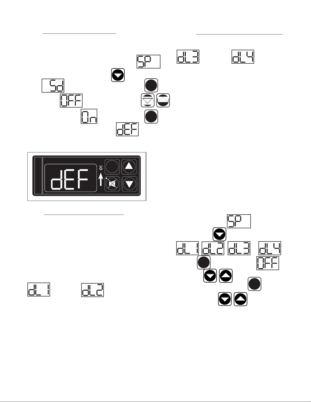
VII. m - STARTING A MANUAL DEFROST CYCLE:
This parameter allows a service technician to start a defrost cycle at any time. This
parameter will override any lockout settings. Follow the instructions to enter the
customer access code on page 7. When the control displays Ther-
mostat Set Point, press the down arrow key until the control display
reads Start Manual Defrost. Press the set button . The
display will show (OFF). Press either arrow key
(ON). The display will show . Press the set button . The
defrost icon will be lit, and the display will read when the unit is
in defrost.
INTELA-TRAUL
°F °C
FREEZER
DEFROST ICON
SET
SET
SET
VII. n - SETTING THE DEFROST LOCKOUTS (contin-
ued):
OFF OFF
140 = 2:00 p.m. 200 = 8:00 p.m.
143 = 2:30 p.m. 203 = 8:30 p.m.
150 = 3:00 p.m. 210 = 9:00 p.m.
153 = 3:30 p.m. 213 = 9:30 p.m.
160 = 4:00 p.m. 220 = 10:00 p.m.
163 = 4:30 p.m. 223 = 10:30 p.m.
170 = 5:00 p.m. 230 = 11:00 p.m.
173 = 5:30 p.m. 233 = 11:30 p.m.
180 = 6:00 p.m. 240* = 12:00 a.m.
183 = 6:30 p.m. 243* = 12:30 a.m.
190 = 7:00 p.m. 010 = 1:00 a.m.
* Denotes not available.
A lockout can not be programmed to start at 12:00 am or 12:30 am
due to conflicts with other internal programs. The defrost lockouts can
not be programmed to run back-to-back. For example, if dL1 is set to
080, then a defrost cycle would be locked out from 8:00 am to 10:00
am. Because of the dL1 setting the dL2 parameter would not let the
user choose a lockout start time before 10:30 am. All lockouts are
preset at the factory to OFF.
VII. n - SETTING THE DEFROST LOCKOUTS:
The defrost lockout parameters allow the customer to prevent the unit from going
into a defrost cycle for two hours during a set time frame. Customers can set up
to four defrost lockout parameters. They are all programmed the same way. The
parameters will be set for the time the lockout is to start. The controller automatically calculates 2 hours from that setting. The options are similar to the 24-hour
clock settings and are in 30-minute increments. Each of the lockout parameters
covers 6 hours of the 24-hour clock. Note: The 24-hour clock must be set for
this feature to operate at the correct time of day. See “Setting the 24-Hour Clock”
on page 8.
OFF OFF
020 = 2:00 a.m. 080 = 8:00 a.m.
023 = 2:30 a.m. 083 = 8:30 a.m.
030 = 3:00 a.m. 090 = 9:00 a.m.
033 = 3:30 a.m. 093 = 9:30 a.m.
040 = 4:00 a.m. 100 = 10:00 a.m.
043 = 4:30 a.m. 103 = 10:30 a.m.
050 = 5:00 a.m. 110 = 11:00 a.m.
053 = 5:30 a.m. 113 = 11:30 a.m.
060 = 6:00 a.m. 120 = 12:00 p.m.
063 = 6:30 a.m. 123 = 12:30 p.m.
070 = 7:00 a.m. 130 = 1:00 p.m.
Follow the instructions to enter the customer access code on page 7.
When the control displays Thermostat Set Point, press
the down arrow key until the control the display reads
or . Press the
set button . The display will show Off. Press
the arrow keys to set the start time. When the correct
time is displayed, press the set button . You can press the
up or down arrow keys to scroll to the next parameter,
or wait 30 seconds for the control to return to normal operation.
SET
SET
-10-
Page 12

VII. PATENTED MICROPROCESSOR CONTROL (continued)
VII. o - ADJUSTING THE ROOM TEMPERATURE OFFSET:
The room temperature offset parameter allows a service technician or end
user the ability to have the display show a temperature that is within three
degrees of the actual temperature being read by the cabinet air sensor.
This allows for continuity of reading between different temperature read-
ing devices. (i.e.: thermistor vs. thermocouple vs. handheld thermometer)
This parameter is preset at the factory to “0” or no offset.
Follow the instructions to enter the customer access code on page 7.
When the control displays Thermostat Set Point, press
the down arrow key until the control display reads
Room Temperature Offset. Press the set button . Use the
arrow keys to adjust the offset to your desired
setting. When the display shows the offset you want press the set
button . The display will then read Room
Temperature Offset. You can use the up or down arrow keys
to scroll to the next parameter, or wait 30 sec-
onds for the control to return to normal operation.
SET
SET
VII. p - VIEWING SENSOR TEMPERATURES:
These parameters allow a service technician or customer to view the
temperature of all sensors within the unit. The temperatures cannot
be adjusted.
Follow the instructions to enter the customer access code on page 7.
When the control displays T h e r m o s t a t S e t P o in t,
press the down arrow key until the display reads Evaporator
Coil or Cabinet Air or Liquid Line
Press the SET button to view the current sensor
value. Press the SET button when done. Press the UP or DOWN arrow
keys to scroll through the parameters, or wait 30
seconds for the control to return to normal operation.
SET
-11-
Page 13
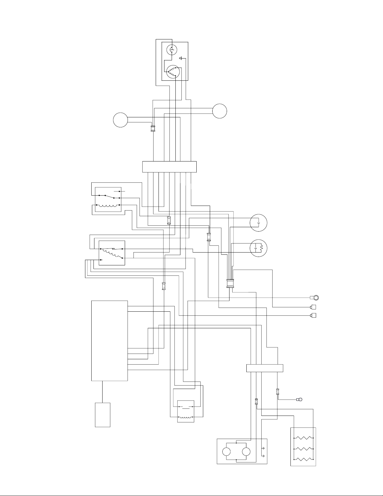
VIII. WIRING DIAGRAM
(CONDENSING UNIT CONNECTOR)
7
BLACK
(CABINET CONNECTOR)
GREEN
WHITE
ORANGE
GRAY
C
WHITE
BLUE
CAPACITOR
RUN
CAPACITOR
START
POWER CORD
L2
C
WHITE
K
GREEN
BLACK
9
8
BLACK
BLACK
PINK
PINK
(MIT II RELAY BOX)
YELLOW
PURPLE
BLUE
BLUE
WHITE
WHITE
GREEN
1
465
3
2
(POTENTIAL RELAY)
(CONDENSER FAN RELAY)
(FREEZER ONLY)
D
GREEN
D
GREEN
WHITE
ORANGE
BLACK
EVAP
WHITE
D
D
D
D
65432
1
YELLOW
GREEN
RED
D
1
BLUE
PURPLE
GREEN
YELLOW
BLUE
WHITE
BLUE
PURPLE
WHITE
CONDENSER FAN
(FREEZER ONLY)
FAN
FAN
EVAP
EVAPORATOR FANS
DOOR HEATERS
COND
FAN
2
1
3
4
COMPRESSOR
RELAY
L1
COMPRESSOR
S
R
C
SOL
(SOLENOID VALVE)
YELLOW
RED
1
5
2
4
COMPRESSOR
DEFROST
POWER
BLOWER
DOOR HEATER
NEUTRAL
COMPRESSOR
5 4 3 2 1 2 1
PURPLE
BLUE
BLUE
WHITE
(MIT II CONTROL BOX)
RED
YELLOW
S
Note: Refer to the wiring diagram below for any service work performed by a qualified technician.
-12-
Page 14

IX. TROUBLE SHOOTING GUIDE
PROBLEM POSSIBLE SOLUTION
1. Condensing unit fails to start. a. Check if cord & plug has been disconnected.
b. Clean Condenser
2. Condensing unit operates for prolonged periods or
continuously.
a. Are doors closed properly?
b. Dirty condenser or filter. Clean properly.
c. Evaporator coils iced. Needs to defrost. See instructions for starting a manual
defrost cycle p. 10.
3. Food Compartment is too warm.
a. Check door(s) and gasket(s) for proper seal.
b. Check if a large quantity of warm food was recently added or the door was kept
(Note: Compressor may be cycling ON/OFF frequently)
open for a long period of time.
c. Microprocessor Control setting is too high. Readjust per instructions on p. 7 and 8.
d. Clean Condenser
4. Food Compartment is too cold. a. Check if a large quantity of very cold or frozen food has recently been added. Allow
adequate time for the cabinet to recover its normal operating temperature.
b. Adjust the microprocessor control to warmer setting. Readjust per instruction on p.
7 and 8.
5. Condensation on exterior surface. a. Check door(s) alignment and gaskets for proper seal.
b. Condensation on the exterior surface of the unit is perfectly normal during periods
of high humidity.
c. Check perimeter heat setting and increase setting if <100.
6. Product temperature in rail too warm. a. Product held in plastic pans.
b. Room ambient temperature exceeds 86
temperature.
c. Air drafts disrupting air-flow over product pans.
d. Food debris blocking air discharge and/or return vents.
e. Product loaded in pans above 360F.
f. Rail inserts missing.
g. Base doors left open.
h. Pan(s) missing.
7. Compressor hums & does not start. a. Call for service.
8. Water on floor. a. Make sure drain valve is closed.
b. If water is from system condensate pan, install wicking card kit.
0
F. Operate in room ambient below this
-13-
Page 15

X. SERVICE ASSISTANCE
X. a - SERVICE INFORMATION:
Before calling for service, please check the following:
Is the electrical cord plugged in?
Is the fuse OK or circuit breaker on?
Clean condenser coil
Is the power switch on?
If after checking the above items and the unit is still not operating properly, please contact an authorized Traulsen service agent. You may obtain the name
of a service agent from the Service Directory page of our web site: www.traulsen.com. Please note, you will be required to register for a login name and
pass code to access our directory. If service is not satisfactory, please contact our in-house service department at:
Traulsen
4401 Blue Mound Road
Fort Worth, TX 76106
(800) 825-8220
Traulsen reserves the right to change specifications or discontinue models without notice.
X. b - SERVICE SUPPORT INFORMATION:
To purchase replacement parts or to speak to service support for Traulsen and most Hobart refrigeration units please contact our Ft. Worth facility by phone
at 800-825-8220 or fax to 817-740-6748 (parts) or 817-740-6757 (service).
Note: When calling for spare parts or service support, please make sure you have model and serial number of unit available.
To source service support locally follow instructions below for nearest authorized service agent. Please note, you will be required to register for a login
name and pass code to access our directory.
1. Log onto www.traulsen.com
2. Select Contact Us/Dealer Directory (top right of screen)
3. Click on Service Directory tab
4. Select state by using the drop down box
5. Select Go
X. c - WARRANTY REGISTRATION:
The warranties for your new Traulsen unit may be registered with us by contacting our Ft. Worth facility directly by phone at 800-825-8220 or you may
register on line. Please note, you will be required to register for a login name and pass code to access our on line registration.
1. Log onto www.traulsen.com
2. Select Contact Us/Dealer Directory (top right of screen)
3. Select Warranty Registration (lower right of screen)
4. Fill out information requested
5. Select Submit to complete unit warranty registration
-14-
Page 16

XI. WARRANTIES
STANDARD DOMESTIC WARRANTY
TRAULSEN warrants new equipment to the original purchaser, when installed within the United States against defective material and workmanship for one
(1) year from the date of original installation. Under this warranty, TRAULSEN, will repair or replace, at its option, including service and labor, all parts found
to be defective and subject to this warranty. The compressor part is warranted for an additional four (4) years. During this period TRAULSEN, will supply
replacement compressor (s) if deemed defective, however, all installation, recharging and repair costs will remain the responsibility of the owner. However, all
installation and repair costs will remain the responsibility of the owner.
This warranty does not apply to damage resulting from fire, water, burglary, accident, abuse, misuse, transit, acts of God, terrorism, attempted repairs, improper
installation by unauthorized persons, and will not apply to food loss.
For TRAULSEN units purchased with a remote feature, standard warranty will apply only to those components contained within the unit to the point of connection of the refrigeration lines leading to the remote compressor.
THERE ARE NO ORAL, STATUTORY OR IMPLIED WARRANTIES APPLICABLE TO TRAULSEN, INCLUDING BUT NOT LIMITED TO, ANY IMPLIED WARRANTY OF
MERCHANTABILITY OR FITNESS FOR ANY PARTICULAR PURPOSE WHICH EXTEND BEYOND THE DESCRIPTION ON THE FACE HEREOF. TRAULSEN SHALL
HAVE NO OBLIGATION OR LIABILITY FOR CONSEQUENTIAL OR SPECIAL DAMAGES, GROWING OUT OF OR WITH RESPECT TO THE EQUIPMENT OR ITS SALE,
OPERATION OR USE, AND TRAULSEN NEITHER ASSUMES NOR AUTHORIZES ANYONE ELSE TO ASSUME FOR IT ANY OBLIGATION OR LIABILITY IN CONNECTION WITH THE EQUIPMENT OR ITS SALE, OPERATION OR USE OTHER THAN AS STATED HEREIN.
PATENTED MICROPROCESSOR CONTROL WARRANTY
TRAULSEN, warrants to the original purchaser of the microprocessor control when installed as part of the Refrigeration/Hot Food Equipment manufactured
and sold by TRAULSEN, to be free of defects in material and workmanship under normal service and use for a period of two (2) years from the date of instal-
lation. Under this warranty statement, TRAULSEN will repair or exchange at TRAULSEN’S discretion, F.O.B. factory, any part of said control, which proves to
be defective. Inspection by the TRAULSEN Service Department of parts claimed defective shall be final in determining warranty status. The warranty is to
include repair or exchange of any defective In-Warranty control or part (s) of said control for:
Part (s) –Any TRAULSEN microprocessor control supplied part (s) found to be defective.
Labor –The labor charges from a TRAULSEN Certied Service Agent to effect the repair or exchange of the defective part(s).
“Defective Part Return” – All claimed defective part(s) must be returned to TRAULSEN for defect validation within
30 days from the date of the repair. Failure to return all claimed defective part(s) to TRAULSEN will invalidate the warranty claim, this warranty statement,
and forfeit payment for those repairs effected.
This warranty does not apply to damage resulting from fire, water, burglary, accident, abuse, misuse, transit, acts of God, terrorism, attempted
repairs, improper installation by unauthorized persons, and will not apply to food loss, and will not apply if said equipment is located outside
The United States.
INTERNATIONAL COMMERCIAL WARRANTY
TRAULSEN warrants to the original purchaser the Refrigeration Equipment manufactured and sold by it to be free from defects in material and workmanship under normal use and service for a period
of one (1) year from date of shipment. Under this warranty, TRAULSEN will reimburse the purchaser for the replacement of any part of said equipment (excluding dryers & refrigerant gas) which then
proves to be defective. This warranty does not apply to damage resulting from fire, water, burglary, accident, abuse, misuse, transit, acts of God, terrorism, attempted repairs, improper
installation by unauthorized persons, and will not apply to food loss.
TRAULSEN’S standard warranty does not apply to Export Sales. Rather, for a period of one (1) year from date of original installation not to exceed Fifteen (15) months from date of shipment from fac-
tory, TRAULSEN:
Will replace, F.O.B. factory, any defective parts normally subject to warranty.
Will not cover the cost of packing, freight or labor such costs being the sole responsibility of the dealer/end user.
THIS WARRANTY IS IN LIEU OF ALL OTHER WARRANTIES EITHER EXPRESSED OR IMPLIED AND CONSTITUTES TRAULSEN’S FULL OBLIGATION AND LIABILITY. WARRANTIES NOT AVAILABLE
ON REMOTE MODELS.
(for Canadian warranties see domestic US warranty)
-15-
Page 17

XII. SERVICE PARTS LIST
Note: Part numbers listed are for standard products as currently manufactured. For products manufactured as other than standard, please
contact the factory.
ITEM DESCRIPTION PART NUMBER
CASTERS ALL MODELS
6” ADJUSTABLE CASTER NO LOCK SER-60538-00
6” ADJUSTABLE CASTER WITH LOCK SER-60538-01
4 5/8” ADJUSTABLE CASTER NO LOCK SER-60536-00
4 5/8” ADJUSTABLE CASTER WITH LOCK SER-60536-01
3 1/2” ADJUSTABLE CASTER NO LOCK SER-60567-00
3 1/2” ADJUSTABLE CASTER WITH LOCK SER-60567-01
LEGS ALL MODELS
6” LEG SER-60542-00
DOORS MODELS TS048 & TS072 (right section)
DOOR ASSEMBLY, HINGED LEFT 200-60791-00
DOOR ASSEMBLY, HINGED RIGHT 200-60791-01
DOOR GASKET 341-60197-00
DOORS MODELS TS066, TS072 & TS090 (left section)
DOOR ASSEMBLY, HINGED LEFT 200-60789-00
DOOR ASSEMBLY, HINGED RIGHT 200-60789-01
DOOR GASKET 341-60197-02
DRAWERS 2 DRAWER 6” DEEP PAN MODELS TS048 & TS072 (right section)
DRAWER ASSEMBLY 550-10108-00
DRAWER FACE ASSEMBLY 550-10114-00
DRAWER FRAME ASSEMBLY 550-10104-00
DRAWER FRAME INSERT SER-60539-00
DRAWER GASKET 341-60176-07
DRAWER ROLLER 344-60155-00
DRAWER ADAPTER BAR 701-61198-00
DRAWERS 2 DRAWER 6” DEEP PAN MODELS TS066, TS072 & TS090 (LEFT SECTION)
DRAWER ASSEMBLY 550-10190-00
DRAWER FACE ASSEMBLY 550-10194-00
DRAWER FRAME ASSEMBLY 550-10188-00
DRAWER FRAME INSERT SER-60568-00
DRAWER GASKET 341-60176-09
DRAWER ROLLER 344-60155-00
DRAWER ADAPTER BAR 701-61258-00
DRAWERS 3 DRAWER 4” DEEP PAN MODELS TS048 & TS072 (RIGHT SECTION)
DRAWER ASSEMBLY 550-10098-00
DRAWER FACE ASSEMBLY 550-10099-00
DRAWER FRAME ASEMBLY 550-10104-00
DRAWER FRAME INSERT SER-60541-00
DRAWER GASKET 341-60176-06
DRAWER ROLLER 344-60155-00
DRAWER ADAPTER BAR 701-61198-00
-16-
Page 18

XII. SERVICE PARTS LIST (continued)
Note: Part numbers listed are for standard products as currently manufactured. For products manufactured as other than standard, please
contact the factory.
ITEM DESCRIPTION PART NUMBER
DRAWERS 3 DRAWER 4” DEEP PAN MODELS TS066, TS072 & TS090 (left section)
DRAWER ASSEMBLY 550-10191-00
DRAWER FACE ASSEMBLY 550-10196-00
DRAWER FRAME ASEMBLY 550-10188-00
DRAWER FRAME INSERT SER-60569-00
DRAWER GASKET 341-60176-10
DRAWER ROLLER 344-60155-00
DRAWER ADAPTER BAR 701-61258-00
KEY DOOR LOCKS (all models)
Key 346-28924-42
SHELVES MODEL TS048 (3 shelves maximum per door)
SHELF PLATED 340-60230-01
MODEL TS066
SHELF PLATED LEFT SECTION 340-60294-00
SHELF PLATED RIGHT SECTION 340-60294-01
MODEL TS072
SHELF PLATED LEFT SECTION 340-60294-00
SHELF PLATED RIGHT SECTION 340-60231-03
MODEL TS090
SHELF PLATED LEFT SECTION 340-60294-00
SHELF PLATED RIGHT SECTION 340-60294-01
SHELF PLATED CENTER SECTION 340-60295-00
SHELF MOUTING PINS ALL MODELS
SHELF PIN 344-24759-02
RAIL COVERS MODEL TS048
HINGED LIFT UP LID 500-60722-00
MODEL TS066
HINGED LIFT UP LID 500-60722-01
MODEL TS072
HINGED LIFT UP LID 500-60722-02
MODEL TS090
HINGED LIFT UP LID 500-60722-03
RAIL AIR BAFFLES MODEL TS048
AIR BAFFLE BACK 614-60254-00
AIR BAFFLE FRONT 614-60254-01
1/4-20 THUMB SCREW & RETAINING RING SER-60570-00
MODEL TS066
AIR BAFFLE BACK 614-60252-02
AIR BAFFLE FRONT 614-60252-01
1/4-20 THUMB SCREW & RETAINING RING SER-60570-00
-17-
Page 19

XII. SERVICE PARTS LIST (continued)
Note: Part numbers listed are for standard products as currently manufactured. For products manufactured as other than standard, please
contact the factory.
ITEM DESCRIPTION PART NUMBER
RAIL AIR BAFFLES MODEL TS072
AIR BAFFLE BACK 614-60257-00
AIR BAFFLE FRONT 614-60257-01
1/4-20 THUMB SCREW & RETAINING RING SER-60570-00
MODEL TS090
AIR BAFFLE BACK 614-60250-02
AIR BAFFLE FRONT 614-60250-01
1/4-20 THUMB SCREW & RETAINING RING SER-60570-00
RAIL ADAPTER BARS MODELS TS048 & TS090 (models only)
ADAPTER BAR 701-61444-00
LOUVERS ALL MODELS
LOUVER PANEL 500-60729-00
FILTERS MODELS TS048
FILTER 341-60062-05
MODELS TS066, TS072 & TS090
FILTER 341-60062-07
WHITE PLASTIC
CUTTING BOARDS MODELS TS048 & TS072
WHITE PLASTIC CUTTING BOARD 340-60172-00
MODEL TS066
WHITE PLASTIC CUTTING BOARD 340-60172-02
MODEL TS090
WHITE PLASTIC CUTTING BOARD 340-60172-06
COMPOSITE
CUTTING BOARDS MODELS TS048 & TS072
COMPOSITE CUTTING BOARD 340-60171-01
MODELS TS066
COMPOSITE CUTTING BOARD 340-60171-03
MODELS TS090
COMPOSITE CUTTING BOARD 340-60171-02
WICKING CARD KIT ALL MODELS
WICKING CARD KIT SER-60571-00
-18-
Page 20

HOURS OF OPERATION:
Monday thru Friday 7:30 am - 4:30 pm CST
Quality Refrigeration
Traulsen
4401 Blue Moud Road Fort Worth, TX 76106
Phone (800) 825-8220 Fax (817) 740-6757
Website: www.traulsen.com
© 2010 Traulsen - All Rights Reserved
 Loading...