

Page 1
Quality Refrigeration
OWNER’S MANUAL
Instructions for the installation, operation
and maintenance of Traulsen:
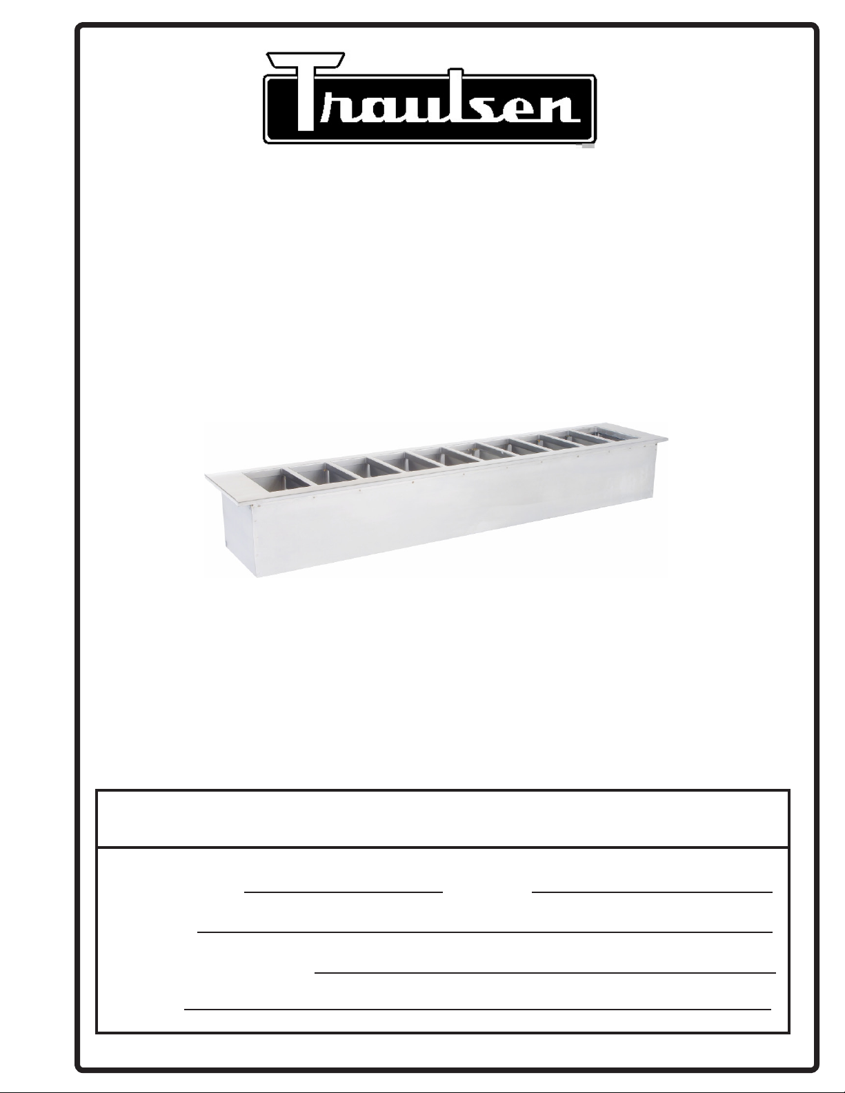
TRD-Series Refrigerant Drop-In Pan Chillers
Models TRD027, TRD034, TRD041, TRD048, TRD055, TRD062, TRD069, TRD076, TRD083 & TRD090
This Traulsen unit is built to our highest quality standards. We build our refrigerators this way as a matter of pride. This philosophy has
made Traulsen the leader in commercial refrigeration since 1938. We thank you for your choice and condence in Traulsen equipment
and we know you will receive many years of utility from this equipment.
All Traulsen units are placed on a permanent record le with the service department. In the event of any future questions you may have,
please refer to the model and serial number found on the name tag axed to the unit. Should you need service, call us on our toll free
number, 800-825-8220 between 7:30 am - 4:30 pm CST, Monday thru Friday. You may also log onto www.traulsen.com for further information. It is our pleasure to help and assist you in every possible way.
INSTALLER
COMPLETE THE FOLLOWING INFORMATION PRIOR TO UNIT INSTALLATION
INITIAL START DATE: SERIAL NO.
MODEL TYPE:
COMPANY/INDIVIDUAL NAME:
INSTALLER:
FORM NUMBER TR36011 (REV. 12-21-16) P/N 375-60349-00
Page 2
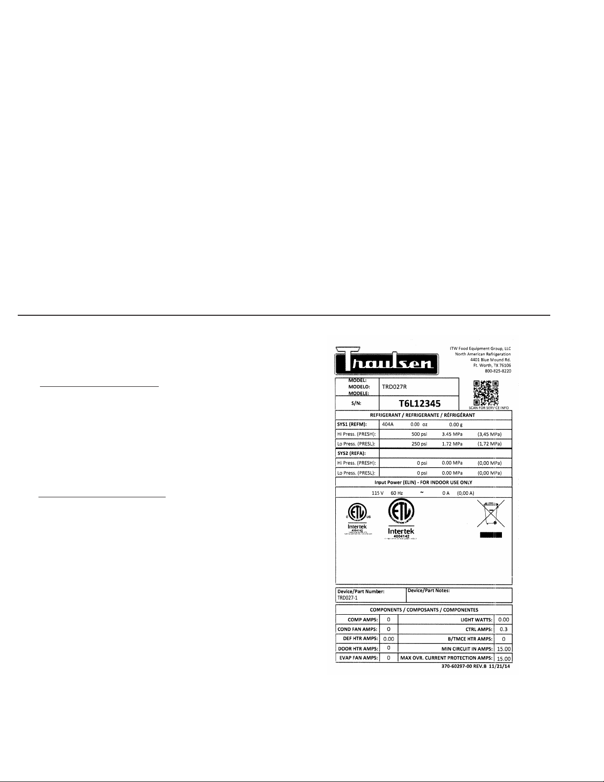
TABLE OF CONTENTS
I. THE SERIAL TAG Page 1
a) Serial Tag & Location Page 1
b) Reading The Serial Tag Page 1
II. RECEIPT INSPECTION Page 2
III. INSTALLATION Page 2
a) Installing The Pan Chiller Page 2
b) Refrigeration Lines Remote Models Page 2
IV. ELECTRICAL CONNECTIONS Page 2
a) Electrical Connections Page 2
b) Cord Connected Units Self-Contained Page 2
V. PRESTART CHECKS Page 2
a) Defrost Time Clock Settings Page 2-3
b) Leaving Food Product Throughout Night Page 3
c) Temperature Control Settings Page 3
VI. OPERATION Page 3
a) Pan Chiller Page 3
b) Shutdown For Extended Periods Page 3
VII. MAINTENANCE PROCEDURES Page 4
a) Cleaning Page 4
VIII. CONDENSING UNIT SELF-CONTAINED Page 4
IX. TROUBLE SHOOTING Page 5
X. SERVICE/WARRANTY INFORMATION Page 5
XI. WARRANTIES Page 6
I. THE SERIAL TAG
I. a - SERIAL TAG & LOCATION:
The serial tag is a permanently axed label on which is recorded vital
electrical and refrigeration data about your Traulsen product, as well as
the model and serial number. This tag is located inside the top opening
on all standard TRD-Series Pan Chiller models. Prior to installation, test
the electrical service to assure that it agrees with the specications of
the equipment marked on the serial tag.
I. b - READING THE SERIAL TAG
• Model = The model # of your Traulsen unit
• (S/N) Serial Number = The permanent ID# of your Traulsen unit
• Refrigerant SYS1= System 1 Refrigerant type used and refrigerant charge
• Design Pressure= System 1 High and Low Pressure
• Refrigerant SYS2= System 2 Refrigerant type used and refrigerant charge
• Design Pressure= System 2 High and Low Pressure
• Volts = Voltage
• Hz = Cycle
• Total Current = Maximum amp draw
• Min Circuit Amps = Minimum circuit ampacity
• Agency Labels = Designates agency listings
This unit is listed to UL 471, CSA 120 and NSF 7 by an approved NRTL.
Consult the factory or unit data plate for approval information.
• Components = Component Ratings
-1-
Page 3
II. RECEIPT INSPECTION
IV. ELECTRICAL CONNECTIONS
II. a - RECEIPT INSPECTION:
Carefully inspect your Traulsen unit for damage during delivery. If
damage is detected, you should save all crating materials and make
note on the carrier’s Bill of Lading describing the damage. A freight
claim should be led immediately. If damage is subsequently noted
during or immediately after installation, contact the respective carrier
and le a freight claim. There is a ve (5) day limit to le freight damage
with the carrier. Under no condition may a damaged unit be returned
to Traulsen without rst obtaining written permission (return authorization). You may contact Traulsen customer care at 800-333-7447.
III. INSTALLATION
III. a - INSTALLING THE PAN CHILLER:
Self-contained units must be installed with sucient air circulation
for the condensing unit. Venting must include provisions for both air
intake and exhaust. Failure to provide adequate ventilation may cause
severe compressor damage, and will void warranty.
Both self-contained and remote units require a counter cut-out that
is 3/8 inch (0.3175cm) larger than the overall outer dimension of the
pan chiller. Refer to the specication sheet for your particular unit.
IV. a - ELECTRICAL CONNECTIONS:
Refer to the wiring diagram shipped with the unit located inside the compressor compartment or on the back of the unit.
IV. b - CORD CONNECTED UNITS SELF-CONTAINED
MODELS:
Plug the unit into a properly sized outlet. See serial tag located
inside lower storage cabinet for proper circuit sizing.
WARNING: THIS MACHINE IS PROVIDED
WITH A THREE-PRONGED GROUNDING PLUG. THE OUTLET
TO WHICH THIS PLUG IS CONNECTED MUST BE PROPERLY GROUNDED. IF THE RECEPTACLE IS NOT THE PROPER
GROUNDING TYPE, CONTACT AN ELECTRICIAN.
V. PRESTART CHECKS
V. a - DEFROST TIME CLOCK SETTINGS:
Never apply power to a Traulsen unit without setting the time
clock to the correct time of day. (Note: All time clocks are
preset at the factory to turn the pan chiller “o at 12:00 midnight and back on at 5:00 a.m.” unless otherwise instructed
by customer).
III. b - REFRIGERATION LINES REMOTE MODELS:
WARNING: REFRIGERATION LINES ARE SHIPPED UNDER PRESSURE.
USE CAUTION WHEN OPENING LINES.
Location of the refrigeration lines varies depending on installation
needs. The suction line is 3/8” copper tubing and is marked “Suction”.
The supply line is 1/4” copper. See “Electrical Connections” section for
wiring instructions.
A control box, expansion valve, solenoid valve, time clock and temperature controller, is supplied with the drop-in. All drop-in units are
shipped with this control box loose. Refrigeration lines and power
supply must be attached to this box then routed to the drop-in.
Cut refrigeration tubing with tube cutter (not a hacksaw) and de burr
end of tube. De grease tubing prior to eld connection. Use Silfos 5%
for refrigerant line brazing. 50/50 or cold solder is not acceptable.
If no holding charge is evident upon opening lines, contact Traulsen
Parts and Service Department at (800) 825-8220 immediately.
On self-contained units, the time clock is located on the
compressor compartment housing.
To set the time of day, rotate the disc in the direction of the
arrows (clockwise rotation) to align the hands to the correct
time of day (see page 3).
To change time clock setting, the tripper pins must be recongured. Each pin on the time clock represents 15 minutes.
Tripper pins pulled out away from center of time clock represent refrigeration o. Tripper pins pushed toward center
indicate refrigeration on. If system runs only during normal
working hours and food has been removed from pan chiller
at night, the time clock must be set to shut pan chiller o at
closing time and to turn on one hour prior to putting the food
in the pan chiller the next day (see page 3).
For system charge, follow remote refrigeration system manufacturer’s
instructions.
-2-
Page 4

V. PRESTART CHECKS
V. PRESTART CHECKS (continued)
V. a - DEFROST TIME CLOCK SETTINGS: (continued)
On Cycle
Pins In
Time Shown
With Clock Set
At 8:00 a.m.
O Cycle
Pins Out
V. b - LEAVING FOOD PRODUCT IN THROUGHOUT THE
NIGHT:
If leaving the food product in the pan chiller overnight, defrost time
clock needs to be set to cycle o and on throughout the night. Time
clock must be set to run for 15 minutes on and 60 minutes o consistently until the night cover is removed the next day. To change the
setting, set the pins to desired cycle times. Each tripper pin represents 15 minutes. Tripper pins pulled out away from center of time
clock represent refrigeration o. Tripper pins pushed toward center
indicate refrigeration on. Make sure time clock is set to correct time
of day (see below).
V. c - TEMPERATURE CONTROL SETTINGS:
All temperature settings are preset at the factory but local
conditions may necessitate slight adjustments.
On both self-contained and remote units, the temperature
control marked should be set at 23º F (-5°C) with a 3º F dierential. The operating display range should read between 20ºF
(-6.6°C ) and 28º F (-2.2°C ). The temperature control settings
are “locked” to avoid unauthorized adjustments. Therefore,
an authorized service technician must make adjustments to
the set point.
VI. OPERATION
VI. a - PAN CHILLER:
Note: Pan chiller system Must BE periodically shut down for
proper defrost and functioning of the unit (see instructions
on pages 2-3 for defrost time clock settings ).
To insure proper food temperatures are maintained in exposed insert pans, the following conditions are required per
NSF Standards:
1. No direct air blowing on food product from other equipment in the kitchen (max air velocity 50 FPM).
Plastic wrap should be placed over exposed food prior to closing
the night cover to help prevent condensation from getting into the
food. The night cover must be closed if food is being left in the pan
chillers overnight.
Time Shown
With Clock Set
At 8:00 a.m.
O Cycle
Pins Out
On Cycle
Pins In
2. Room ambient temperatures of 86ºF (30°C ) and relative
humidity of 50% or less around working area of pan chiller.
3. Food sits a minimum of 1 inch below top of insert pan.
4. All shelving mounted over insert pans (with heated equipment above it) must be insulated.
5. Occasional stirring of certain foods may be required in
order to maintain consistent temperatures.
6. Some food products chill faster than others i.e., lettuce,
diced tomatoes, etc. Double pans will help prevent over
chilling.
7. For remote refrigerators with pan chiller systems, it is imperative that the existing refrigeration equipment must be
sized properly and in good working condition.
VI. b - SHUTDOWN FOR EXTENDED PERIODS:
For an extended period of time, disconnect the electrical
power. As soon as the divider bars have defrosted, wipe out
the pan chiller cavity.
-3-
Page 5

VII. MAINTENANCE PROCEDURES (continued)VII. MAINTENANCE PROCEDURES
VII. a - CLEANING:
WARNING: DISCONNECT ELECTRICAL POWER
SUPPLY BEFORE CLEANING ANY PARTS ON THE UNIT.
DO NOT HOSE DOWN OR POUR WATER OR LIQUID
CLEANERS IN THE PAN CHILLER COMPARTMENT AS THIS
COULD CAUSE DAMAGE TO THE PAN CHILLER AND REQUIRE
AN AUTHORIZED SERVICE TECHNICIAN TO REPAIR. FAILURE
TO FOLLOW THIS INSTRUCTION WILL VOID WARRANTY.
The drain is provided for condensate runo during the defrost
cycle. Use a soft cloth or sponge to clean the pan chiller. Always exercise caution to avoid getting the fan assembly wet.
There are two drains in the pan chiller. Both drains must be
cleared/cleaned regularly for proper operation. Drains should
be cleaned a minimum of once a month.
The top drain in the pan chiller compartment (see below).
A removable screen has been provided to prevent the drain
from clogging. Clear drain of dirt and debris so that condensate can ow freely. This drain is provided for condensate run
o from defrosting of chiller plates.
VII. a - CLEANING: (continued)
Pan Chiller Fan
Mounting Holes
Drain
Pan Chiller Fan
Mounting Holes
VIII. CONDENSING UNIT SELF-CONTAINED
VIII. a - CONDENSING UNIT SELF-CONTAINED MODELS:
WARNING: DISCONNECT ELECTRICAL POWER SUPPLY
BEFORE CLEANING ANY PARTS ON THE UNIT.
The condensing unit coil must be cleaned regularly on self-contained
models for optimal performance. The operating environment will
aect the required frequency of cleaning. However, coils should be
cleaned a minimum of once every three months. Air must be able to
freely circulate through the condenser. Unit performance and operating eciency are signicantly aected by the amount of air passing
through the condenser. Condenser ns that are clogged with dirt
and debris greatly reduce required airow. Failure to keep the coil
ns clean may cause premature compressor failure, which will not
be covered by warranty.
Drain
A second drain located below the fan assembly in the pan
chiller must also be properly maintained and functional. (See
Fig. 5). To access this drain, remove the fan shroud and fan
housing assembly. (A 7/16” hex socket is required to remove
the fan assembly cap screws). Clear drain of dirt and debris
so that condensate can ow freely. This drain is provided for
condensate run o from defrost cycle.
Always run both drain separately to the oor sink.
The condensing unit is located at the bottom of the unit. To access
the condenser coil, remove the slotted access panel to the right of the
controls. The panel is held in place with 6 Philips head sheet metal
screws. Carefully clean dirt and lint from the condenser coil using a
vacuum cleaner or soft brush; do not use a wire brush. These units do
not have a removable lter. Replace slotted access panel. Reconnect
electrical supply.
-4-
Page 6

IX. TROUBLE SHOOTING
IX. a - TROUBLE SHOOTING:
SYMPTOM POSSIBLE CAUSE
1. Compressor fails to operate. a) Power failure.
b) Plug loose in receptacle or unplugged.
c) Blown fuse or tripped circuit breaker.
d) Main power switch is O.
e) Temperature control or time clock not set properly.
2. Condensing unit operates for pro- longed periods or
continuously.
3. Pan Chiller not holding temperature. a) Temperature control and/or time clock not set properly.
a) Evaporator coil is iced up or dirty.
b) Excessive load of warm food.
b) Fan not operating.
c) Coil iced up.
X. SERVICE/WARRANTY INFORMATION
X. a - SERVICE SUPPORT INFORMATION:
To purchase replacement parts or to speak to service support for Traulsen and most Hobart refrigeration units please contact our Ft.
Worth facility by phone at 800-825-8220 or fax to 817-740-6748 (parts) or 817-740-6757 (service).
Note: When calling for spare parts or service support, please make sure you have model and serial number of unit available.
Model Number
Serial Number
]
To source service support locally follow instructions below for nearest authorized service agent. Please note, you will be required to
register for a login name and pass code to access our directory.
1. Log onto www.traulsen.com
2. Select Contact Us/Dealer Directory (top right of screen)
3. Click on Service Directory tab
4. Select state by using the drop down box
5. Select Go
X. b - WARRANTY REGISTRATION:
The warranties for your new Traulsen unit may be registered with us by contacting our Ft. Worth facility directly by phone at 800825-8220 or you may register on line. Please note, you will be required to register for a login name and pass code to access our on
line registration.
1. Log onto www.traulsen.com
2. Select Contact Us/Dealer Directory (top right of screen)
3. Select Warranty Registration (lower right of screen)
4. Fill out information requested
5. Select Submit to complete unit warranty registration
-5-
Page 7

XI. WARRANTIES
v. 100215
For sales of Traulsen refrigeration equipment (“Equipment”) within the United States, Traulsen warrants to the original
purchaser of the Equipment (“Purchaser”) that Traulsen will convey the Equipment free and clear of all liens, security
interests, and encumbrances created by, through, or under Traulsen. Traulsen further warrants that for a period of three (3)
years from the later of either (a) the date of delivery to the common carrier or (b) the date of installation (the “Domestic
Warranty Period”) but in no event, shall the Domestic Warranty Period commence later than 18 months from the date of
delivery to the common carrier unless otherwise agreed upon by the parties in writing, under normal use and given proper
installation and maintenance as determined by Traulsen, the Equipment: (a) will conform to the specifications as provided
by Traulsen (“Specifications”) and (b) will be free from substantial defects in material and workmanship.
The warranty period for compressors shall extend for an additional two (2) years beyond the Domestic Warranty Period. In
the case of a nonconforming compressor, Traulsen shall provide a replacement compressor; however all installation,
recharging, and repair costs shall be the responsibility of Purchaser. In the case of a nonconforming part, Purchaser must
return the part to Traulsen within 30 days from the date of repair. Failure to return a claimed defective part to Traulsen
within the 30 days will waive the right to the warranty claim.
Additionally, Traulsen provides a lifetime warranty on the housing of cam-lift hinges and the workflow handles. In the case
of a non-conforming housing for cam-lift hinge or workflow handle, Traulsen shall provide a replacement part; however
Purchaser shall be responsible for any other replacement costs, including but not limited to installation and labor.
The Domestic Warranty does not apply to: (a) consumable components or ordinary wear items; (b) components that are
removable without the use of tools including but not limited to gaskets, shelf pins, and light bulbs; (c) use of the Equipment
components or parts not supplied by Traulsen or specified by Traulsen in the Operator’s Manual as set forth on Traulsen’s
website; or (d) damage resulting from fire, water, burglary, accident, abuse, misuse, transit, acts of God, terrorism, power
surges, improper installation, or repairs or installation by unauthorized third parties.
For Traulsen units purchased for use with a condenser provided by a third-party, this standard warranty will apply only to
those components contained within the unit to the point of connection of the refrigeration lines leading to the third-party
condenser.
In the event of a breach of the warranties set forth above (the “Domestic Warranty”), Traulsen will, at Traulsen’s option and
as Purchaser’s sole remedy, repair or replace, including labor costs, any nonconforming Equipment, provided that (a) during
the Warranty Period Traulsen is promptly notified in writing upon discovery of the nonconformance with a detailed
explanation of any alleged deficiencies; (b) Traulsen is given a reasonable opportunity to investigate all claims; and (c)
Traulsen’s examination of any alleged defective part confirms such alleged deficiencies and that the deficiencies were not
caused by misuse, neglect, improper installation, unauthorized alteration or repair or improper testing. Traulsen reserves the
right to, at its request, require Purchaser shall ship the alleged defective part to Traulsen for inspection and confirmation of
defect. No Equipment may be returned without Traulsen’s approval.
Purchaser is solely responsible for determining if Equipment is fit for a particular purpose and suitable for Purchaser’s
application. Accordingly and due to the nature and manner of Traulsen’s Equipment, Traulsen is not responsible for the
results or consequences of use, misuse, or application of its Equipment.
THIS DOMESTIC WARRANTY SETS FORTH THE EXTENT OF TRAULSEN’S LIABILITY FOR SALES WITHIN
THE UNITED STATES. EXCEPT AS SET FORTH ABOVE, TRAULSEN MAKES NO WARRANTY OR
REPRESENTATION OF ANY KIND, EXPRESS OR IMPLIED (INCLUDING NO WARRANTY OF
MERCHANTABILITY OR FITNESS FOR ANY PARTICULAR PURPOSE). IN NO EVENT WILL TRAULSEN’S
LIABILITY IN CONNECTION WITH THE AGREEMENT OR SALE OF THE EQUIPMENT EXCEED THE
PURCHASE PRICE OF THE EQUIPMENT AS TO WHICH THE CLAIM IS MADE. IN NO EVENT SHALL
TRAULSEN BE LIABLE FOR ANY LOSS OF USE, LOSS OF PRODUCT, LOSS OF PROFIT, OR ANY OTHER
INDIRECT, INCIDENTAL, SPECIAL, OR CONSEQUENTIAL DAMAGES RESULTING FROM THIS WARRANTY
EVEN IF TRAULSEN HAS BEEN NOTIFIED OF THE POSSIBILITY OF SUCH DAMAGES.
TRAULSEN EQUIPMENT WARRANTY
U.S. Domestic Warranty
-6-
Page 8

HOURS OF OPERATION:
Monday thru Friday 7:30 am - 4:30 pm CST
Traulsen
4401 Blue Moud Road Fort Worth, TX 76106
Phone (800) 825-8220 Fax (817) 740-6757
Website: www.traulsen.com
Quality Refrigeration
© 2016 Traulsen - All Rights Reserved
 Loading...