

Page 1
Trusted
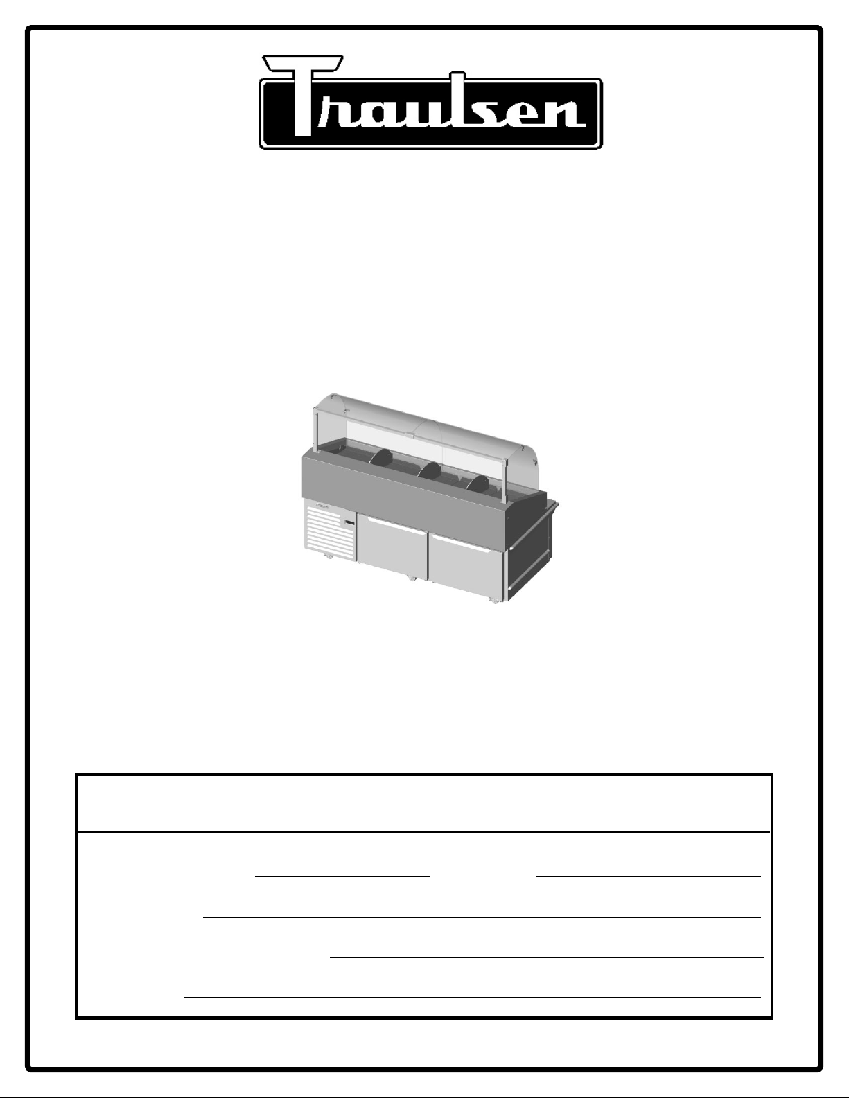
OWNER’S MANUAL
Instructions for the installation, operation and
maintenance of Traulsen’s Seafood Display Cabinet
This Traulsen unit is built to our highest quality standards. We build our refrigerators, freezers and heated
cabinets this way as a matter of pride. This philosophy has made Traulsen the leader in commercial
refrigeration since 1938. We thank you for your choice and confidence in Traulsen equipment and we know
you will receive many years of utility from this equipment.
All Traulsen units are placed on a permanent record file with the service department. In the event of any
future questions you may have, please refer to the model and serial number found on the name tag affixed
to the unit. Should you need service, however, call us on our toll free number, 800-825-8220 between 7:30
am and 4:30 pm CST, Monday thru Friday. It is our pleasure to help and assist you in every possible way.
INSTALLER
COMPLETE THE FOLLOWING INFORMATION PRIOR TO UNIT INSTALLATION
INITIAL START DATE: SERIAL NO.
MODEL TYPE:
COMPANY/INDIVIDUAL NAME:
INSTALLER:
FORM NUMBER TR99999 REV. 7/10 P/N 375-60304-00
Page 2
TABLE OF CONTENTS
Part I - Cabinet Information Part II - Control Information
I. THE SERIAL TAG Page 1
II. RECEIPT INSPECTION Page 2
III. INSTALLATION
a-Location Page 2
b-Packaging Page 2
c-Cord & Plug Page 2
d-Power Supply Page 2
e-Wiring Diagram Page 2
f-Clearance Page 2
g-Adjusting Supports Page 2
IV. OPERATIONS
a-Ice and Product Loading Guidelines Page 3
b-Periodic Ice Melt Removal Page 3
c-Cleaning The Display Area Page 3
d-Cleaning The Fans & Bearing Posts Page 4
e-Interior Arrangements Page 4
f-Transport Latch Page 4
g-Temperature Display Page 4
V. CARE & MAINTENANCE
a-Replacing The Gaskets Page 4
b-Cleaning The Exterior Page 5
c-Cleaning The Interior Page 5
d-Cleaning The Condenser Coil Page 5
VI. OTHER
a-Service Information Page 5
b-Spare Parts Page 5
VII. INTELA-TRAUL
a-Control Features Page 7
b-Alarm Explanations Page 8
c-Control Panel Page 9
d-Parts Assembly Page 9
e-Notes To The User Page 10
f-Enter The Customer Access Code Page 10
g-Customer Service Parameters Page 11
h-Adjusting Thermostat Set Point High Page 11
i-Adjusting Thermostat Set Point Low Page 12
j-Changing The Temperature Scale Page 12
k-Setting The 24-Hour Clock Page 13
l-Setting The Date Page 14
m-Setting Daylight Savings Time Page 14
n-Starting A Manual Defrost Page 15
o-Setting Defrost Lockouts Page 16
p-Adjusting The Room Temperature Offset Page 17
q-Setting The Audible Alarm Style Page 17
r-Viewing Sensor Temperatures Page 18
VIII. TROUBLE SHOOTING GUIDE Page 19
IX. SPARE PARTS LIST Page 20
X. WARRANTY INFORMATION Page 21
XI. WIRING DIAGRAM Page 22
®
PART I. CABINET INFO
FORT WORTH, TX.
SERIAL MODEL
VOLTS Hz PH
TOTAL CURRENT AMPS
MINIMUM CIRCUIT AMPS
MAXIMUM OVERCURRENT PROTECTION AMPS
LIGHTS WATTS
HEATERS AMPS
REFRIGERANT TYPE OZ
DESIGN PRESSURE HIGH LOW
REFRIGERANT TYPE OZ
DESIGN PRESSURE HIGH LOW
370-60294-00 REV (A)
I. THE SERIAL TAG
The serial tag is a permanently affixed sticker on
which is recorded vital electrical and refrigeration data
about your Traulsen product, as well as the model
and serial number. This tag is located in the
refrigeration compartment of all seafood display
cabinets.
READING THE SERIAL TAG
• Serial = The permanent ID# of your Traulsen
• Model = The model # of your Traulsen
• Volts = Voltage
• Hz = Cycle
• PH = Phase
• Total Current = Maximum amp draw
• Minimum Circuit = Minimum circuit ampacity
• Lights = Light wattage
• Heaters = Heater amperage (Hot Food units only)
• Refrigerant = Refrigerant type used
• Design Pressure = High & low side operating
pressures and refrigerant charge
• Agency Labels = Designates agency listings
-1-
Page 3
II. RECEIPT INSPECTION III. INSTALLATION (continued)
All Traulsen products are factory tested for performance
and are free from defects when shipped. The utmost
care has been taken in crating this product to protect
against damage in transit.
You should carefully inspect your Traulsen unit for
damage during delivery. If damage is detected, you
should save all the crating materials and make note on
the carrier’s Bill Of Lading describing this. A freight claim
should be filed immediately. If damage is subsequently
noted during or immediately after installation, contact
the respective carrier and file a freight claim. Under no
condition may a damaged unit be returned without first
obtaining written permission (return authorization).
III. INSTALLATION
III. a - LOCATION:
Select a proper location away from extreme heat or cold.
Allow enough clearance between the unit and the side
wall in order to allow the doors to fully open.
III. b - PACKAGING:
Unit is shipped from the factory strapped to a sturdy
wooden pallet and protected by wood crating. The
crating is attached to the pallet with several screws.
These should first be removed to avoid scratching the
unit when lifting off the crating.
Most exterior surfaces have a protective vinyl covering
to prevent scratching during manufacturing, shipping,
and installation. Remove after install and discard.
To remove the roadshow cabinet from the wooden
pallet start by cutting free the nylon bands. Next,
remove the screws attaching the two metal hold down
brackets to the skid. Slide them out of the caster
channel to remove, thus releasing the roadshow
cabinet from the skid.
NOTE: DO NOT LAY THE UNIT ON ITS SIDE DURING
TRANSPORTATION OR INSTALLATION.
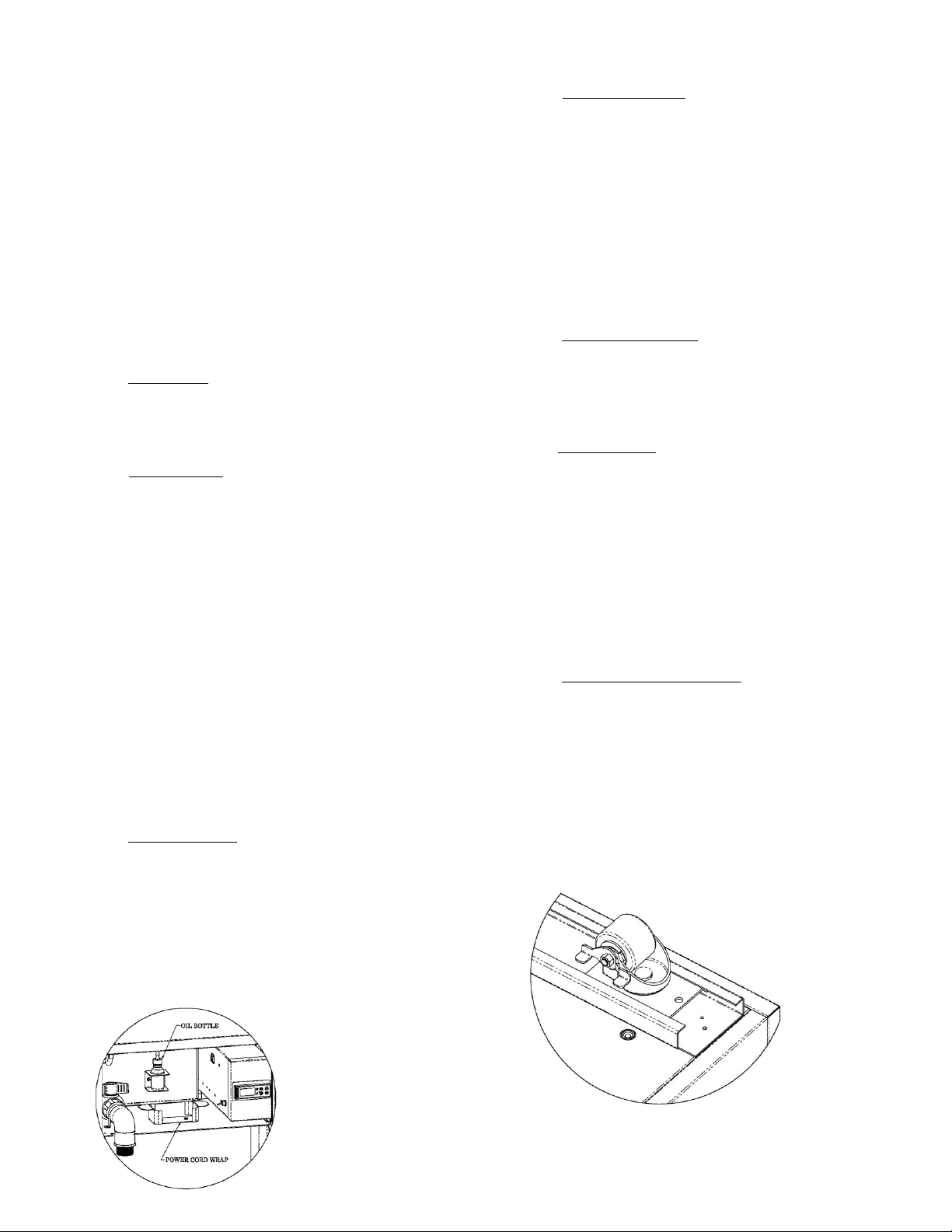
III. c - CORD & PLUG:
An attached cord & plug is provided, shipped coiled
inside the compressor compartment (secured by a
nylon strip). For your safety and protection, this includes
a special three-prong grounding plug. Under no
circumstances should you ever remove the round
grounding prong from the plug.
III. d - POWER SUPPLY:
The supply voltage should be checked prior to
connection to be certain that proper voltage for the
cabinet wiring is available (refer to the serial tag for the
correct unit voltage). Make connections in accordance
with local electrical codes. Use qualified electricians.
Use of a separate, dedicated
circuit is required.
Size wiring to handle indicated load and provide
necessary overcurrent protector in circuit (see amp
requirements on the unit’s serial tag).
III. e - WIRING DIAGRAM:
Refer to the wiring diagram on page 22 for any service
work performed on the unit. Should you require a new
one, please contact Traulsen Service at (800) 8258220, and provide serial number of the unit involved.
III. f - CLEARANCE:
To assure optimum performance of your seafood
display cabinet the condensing unit MUST have an
adequate supply of air for cooling purposes. The
operating location must have 31” minimum clearance
in front of both the customer and operator side louvers.
Select a working location away from extreme heat or
cold. The seafood display cabinet is designed to
operate in temps of 86°F (30°C) or less. Locate the unit
so that air drafts (such as heat, A/C or ventilation) do
not blow on or over the seafood display area.
III. g - ADJUSTING SUPPORTS:
Unit includes 6 factory installed casters, 2 with brakes.
For ease of mobility only the centerline casters are fixed.
To set the brake, using your foot simply push this down
into the locked position. Push up to release.
Adjust the caster location by loosening the two bolts at
the base of each caster (see fig. 2), then slide this along
the mounting channel into the desired position. Tighten
the two bolts to resecure the caster.
NOTE: When adjusting the caster
location please note that these
must always be installed towards
the four corners of the unit, as
well as the center, for proper
cabinet support and mobility.
Select only an appropriate dedicated 20 amp outlet.
To prevent cord and/or
plug damage always
secure the entire cord
on the supplied cord
wrap during transport
(see fig. 1).
Fig. 1
Fig. 2
NOTE: Cabinet is designed to be pushed from the left or
right side for easy mobility. Pushing the cabinet from
either the front (customer side) or back (operator side)
can result in damage to the center set of casters.
-2-
Page 4
IV. OPERATIONS
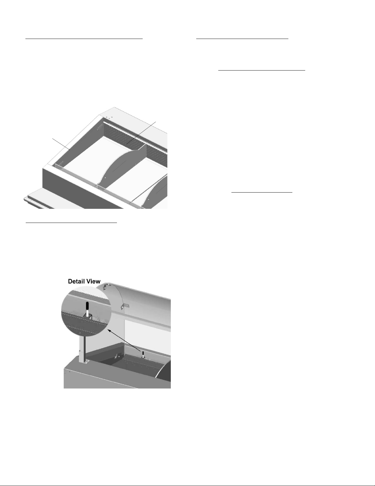
IV a. ICE & PRODUCT LOADING GUIDELINES:
Ice is not required for proper operation, but if used it
should be loaded only up to the level of the lowest air
baffles with product loaded no higher than the rail
perimeter, indicated by load level labels (see fig 3).
NOTE: Do Not Allow Ice to Collect Above
Front Rim Where It Will Block Air-Flow.
Max Ice
Loading
Level
Max Product
Loading Level
Fig. 3
IV b. PERIODIC ICE MELT REMOVAL:
In the event ice is used, the seafood display cabinet is
designed to retain a significant amount of water (from
the inevitable melting) below the display area. Up to 5
gallons of water can be held, and so may need
occasional draining during the day. A float indicator is
provided at the front of the cabinet to notify when
draining is required (see fig. 4).
Fig. 4
To drain the water...
Open the hinged louvered service door that covers the
system end of the unit. It is on the same side as the
refrigerated base doors. Pull it to open. A two foot
flexible hose is provided to facilitate water removal.
Open the valve by rotating the drain handle 90° so that
the handle is in line with the pipe. This will allow the
water to drain out. When the water stops draining, close
the valve and close the louvered service door.
Dispose of the water in an appropriate manner.
IV c. CLEANING THE DISPLAY AREA:
CAUTION: The power should be removed from the unit
by unplugging the power cord from the power source
before doing any cleaning or servicing of this unit.
For The Plastic Sneeze Shield
1) Remove the power from the unit.
2) Remove the plastic sneeze shield pieces by
sliding out of their holders.
3) Remove screws holding the front panels to those
on the side. Push canopy forward to remove from
rear cross brace retaining brackets.
4) Wash the parts with a solution of mild dish soap
and water and a soft cloth. Dry with a soft cloth.
CAUTION:
The use of any soap with chemicals
(ex. Windex, 409, etc.) will cause the
acrylic material to permanently blur.
5) Reinstall the sneeze shield pieces in the rear
cross brace brackets.
For The Display Area
1) Remove the power from the unit.
2) Locate the unit so that the system end of the unit
is located near an appropriate floor drain.
3) Open the louvered service door and position the
enclosed hose over the floor drain.
4) Rotate the red handle on the main drain valve so
that it is in line with the pipe. When you do this
the residual condensate and ice melt will spill out.
5) Remove the ice pans.
6) Remove any cross bars (running front to back) and
the two long support bars (running left to right).
7) Carefully remove the two sections of air baffles by
folding down the vertical member and lifting the
assemblies out of the unit. Care should be taken
not to hit or damage the fan blades.
8) Carefully lift the fan blades off their bearing pins
by holding the fan and lifting straight up. Place
the fan blades in a safe location. They will be
cleaned separately.
9) The display area can now be washed with a hose,
cloth or other means available. All of the water
used will come out of the main drain. Care should
be taken not to hit the fan bearing pins with any
hard objects. These are permanently installed.
10) After the unit is washed, dry with a squeegee,
towels, or other means. Using a clean rag wipe the
bearing pins clean and dry.
11) Replace the cleaned and oiled fan blades (see
procedure following) on the pins.
12) Reinstall the parts in the reverse order, steps 7-2.
13) Close the main drain valve by rotating the red
handle so that it is positioned across the pipe.
CAUTION:
Failure to close the drain pipe will result in the
condensate and ice melt water dripping
onto the floor the next time the unit is used.
-3-
Page 5
IV. OPERATIONS (cont’d)
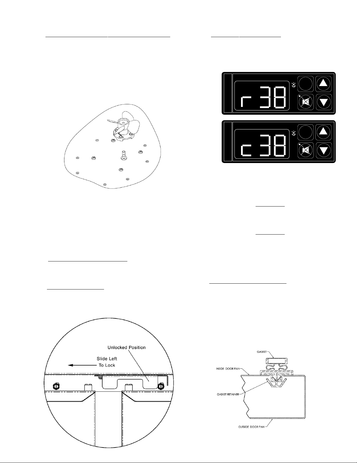
IV d. CLEANING THE FANS AND BEARING POSTS:
NOTE: Fan and bearing MUST be cleaned
and lubricated before every day of use.
1) Using Q-Tips and Alcohol or Mineral Spirits, wipe
the inside of the fan blade hole clean (see fig 5).
2) Use a dry Q-Tip to dry any remaining solvent
inside the bearing surface. Check to make sure no
cleaning material is left in the hole.
Fig. 5
3) Use a soft cloth or Q-Tip with Alcohol or Mineral
Spirits to clean the area around the bearing
surface bottom.
4) Place 8-drops of Traulsen supplied oil (p/n 377-
60061) into the bearing hole.
5) Place the fan onto the cleaned pin and move up
and down to distribute the oil on the bearing pin
6) Repeat the process with the second fan
IV. e - INTERIOR ARRANGEMENTS:
The compartment behind each door is equipped to hold
five 18” x 26” sheet pans.
IV. f - TRANSPORT LATCH:
A transport latch is provided to prevent the doors from
opening while moving. Engage this by sliding the level
to the left (see fig. 6). To disengage slide to the right.
Fig. 6
IV. g - TEMPERATURE DISPLAY:
Two temperatures are displayed on the control,
1) Product Display Area (indicated by “R” see fig. 7) and
2) Cabinet Base (indicated by “C” see fig 8). These flash
alternatively on the control display every ten seconds.
INTELA-TRAUL
°F °C
Fig. 7
REFRIGERATOR
INTELA-TRAUL
°F °C
Fig. 8
REFRIGERATOR
SET
SET
V. CARE & MAINTENANCE
WARNING
DISCONNECT ELECTRICAL POWER SUPPLY
BEFORE CLEANING ANY PARTS OF THE UNIT
WARNING
DO NOT USE A SPRAY HOSE ON ANY AREA
OTHER THAN INSIDE THE DISPLAY WELL.
SPRAYING THE EXTERIOR OR INTERIOR
BASE COULD RESULT IN SIGNIFICANT
CABINET DAMAGE.
V. a - REPLACING THE GASKETS:
To remove a door gasket simply grasp it firmly by one
corner and pull it out of its securing channel. Before
attempting to install a new gasket, both the unit and the
gasket itself must be at room temperature. Insert the
four corners first by using a rubber mallet (or hammer
with a block of wood). After the corners are properly
inserted, work your way towards the center from both
ends by gently hitting with a mallet until the gasket is
completely seated in place (see figure 9 for proper gasket placement).
Fig. 9
NOTE: The gasket may appear too large, but if it is
installed as indicated above it will slip into place.
-4-
Page 6

V. CARE & MAINTENANCE (cont’d)
VI. OTHER
V. b - CLEANING THE EXTERIOR:
Exterior stainless steel should be cleaned with warm
water, mild soap and a soft cloth. Apply with a
dampened cloth wiping in the direction of the metal grain.
Avoid the use of strong detergents and gritty, abrasive
cleaners as they may tend to mar and scratch the
surface. Do NOT use cleansers containing chlorine, this
may promote corrosion of the stainless steel.
Care should also be taken to avoid splashing the unit
with water, containing chlorinated cleansers, when
mopping the floor around the unit.
For stubborn odor spills, use baking soda and water
(mixed to a 1 TBSP baking soda to 1 pint water ratio).
V. c - CLEANING THE CABINET INTERIOR BASE:
For cleaning both stainless steel and anodized
aluminum interiors, the use of baking soda as described
in section “V. b” is recommended. Use on breaker strips
as well as door gaskets. All interior fittings are
removable without tools to facilitate cleaning.
V. d - CLEANING THE CONDENSER COIL:
To clean the condenser open the door to access the
compressor compartment. Proceed to wipe, brush or
vacuum any dirt, lint or dust from the finned condenser
coil, as well as from the the compressor and other
refrigeration system parts. If significant dirt is clogging
the condenser fins or filter, use compressed air to blow
this clear.
Close the door when done.
VI. a - SERVICE INFORMATION:
Before calling for service, please check the following:
Is the electrical cord plugged in?
Is the fuse OK or circuit breaker on?
Is the power switch “ON”?
If after checking the above items and the unit is still not
operating properly, please contact an authorized
Traulsen service agent. A complete list of authorized
service agents was provided along with your Traulsen
unit. If you cannot locate this, you may also obtain the
name of a service agent from the Service/Contact page
of our website: www.traulsen.com.
If service is not satisfactory, please contact our in-house
service department at:
Traulsen
4401 Blue Mound Road
Fort Worth, TX 76106
(800) 825-8220
Traulsen reserves the right to change specifications or
discontinue models without notice.
VI. b - SPARE PARTS:
Spare or replacement parts may be obtained through a
parts supplier or one of our authorized service agents.
A complete list of authorized service agents
accompanies this manual and is also posted on our
company’s official website @ www.traulsen.com.
-5-
Page 7
PART II. CONTROL INFO
-6-
Page 8

VII. INTELA-TRAUL
Your new Traulsen Seafood Display Cabinet is equipped with a state-of-the-art electronic microprocessor
INTELA-TRAUL® control, which precisely regulates operation and provides alarms when problems occur. It is
supplied from the factory completely ready for use but without the audible alarms activated. See pages 8 thru 17 for
more information.
VII. a - INTELA-TRAUL® CONTROL FEATURES:
Internal Time Clock
• Eliminates defrost time clock.
Parameter/Service Levels
• See “Customer / Service Parameters” on Page 10.
Alarms (See the following pages for explanations)
• High Cabinet Air Temperature
• Low Cabinet Air Temperature
• CONDENSERCLEAN*
• Sensor Failures
®
-7-
Page 9

VII. INTELA-TRAUL® (continued)
VII. b - ALARM EXPLANATIONS:
*NOTE: Explanation of alarms assume the audible alarm style is set at a 3-second burst or a
continuous audible alarm. References to the audible alarm do not apply if the audible alarm
style is set to OFF (Refer to page 17 for setting the audible alarm style).
High Cabinet Air Temperature: The audible alarm* will sound and the display will read HI
CAb when the temperature inside the cabinet rises above a pre-programmed limit. The limit is
determined by the type of unit being operated (i.e.: refrigerator/freezer). To turn off the audible
alarm*, press the alarm cancel button. The visual alarm text will continue to display until the
cabinet air temperature falls below the limit. If the temperature does not fall below the limit
within 5 minutes, the audible alarm* will sound again and an additional Call Service message
will display.
POSSIBLE CAUSES:
• Doors open for extended periods of time.
• Large amounts of hot product placed inside the cabinet.
• Condenser coil dirty.
Low Cabinet Air Temperature: The audible alarm* will sound and the display will read Lo
Cab when the temperature inside the cabinet falls below a pre-programmed limit. The limit is
determined by the type of unit being operated (i.e.: refrigerator/ freezer). To turn off the audible
alarm*, press the alarm cancel button. The visual alarm text will continue to display until the
cabinet air temperature rises above the limit. If the temperature does not rise above the limit
within 5 minutes, the audible alarm* will sound again and an additional Call Service message
will display.
POSSIBLE CAUSES:
• No product in unit.
• Failed sensors.
System Leak: The audible alarm* will sound and the display will read Call Service, when the
control detects a leak in the refrigeration system. To turn off the audible alarm*, press the alarm
cancel button. The visual alarm text will remain until a service technician has repaired the unit.
If the condition remains for 24 hours, the audible alarm* will sound again.
POSSIBLE CAUSES:
• Low refrigerant charge.
• Discharge sensor has failed low.
Sensor Failures: The audible alarm* will sound and the display will read Sensor Failure Call
Service, when any of the unit sensors fail to operate. To turn off the audible alarm*, press the
alarm cancel button. The visual alarm text will remain until the sensor has been replaced.
Depending on the function of the sensor, the audible alarm* will sound again in either 5 minutes
or 24 hours.
*Not available on remote models.
-8-
Page 10

VII. c - CONTROL PANEL:
LED FOR °F LED FOR °C
VII. INTELA-TRAUL
INTELA-TRAUL
°F °C
SET
®
(continued)
3-DIGIT (RED)
LED DISPLAY
VII. d - PARTS ASSEMBLY:
COIL SENSOR*
337-60406-03
BLUE
RAIL SENSOR*
337-60405-03
GREEN
REFRIGERATOR
DEFROST ALARM CANCEL
ICON BUTTON
W / LED
CABINET SENSOR*
337-60407-02
YELLOW
HORN*
337-60070-00
INTELA-TRAUL**
HORIZONTAL
CONTROLLER
337-60403-00
25 PIN
CONNECTOR
P1
-9-
RAIL AIR SENSOR
EVAP COIL SENSOR
CABINET LINE SENSOR
CONNECTOR J1
*= Can be ordered seperately
**=Requires unit Model No. & S/N to place order.
Page 11

VII. INTELA-TRAUL® (continued)
VII. e - NOTES TO THE USER:
You only have 20-30 seconds between button pushes. If you take longer than 30 seconds, the controller will revert back to
displaying the rail and box temperature. If you enter the wrong security code, the controller will revert back to displaying the
rail and box temperature. You can exit the parameters at any time by pressing the alarm cancel button or by waiting 20-30
seconds.
VII. f - ENTER THE CUSTOMER ACCESS:
Use the security code 0, A, 1 and the following instructions:
Press the set button . The display will read Customer/Service Access.
Press the set button .
SET
SET
The display will show three zeros with the left zero flashing
Press the set button .
SET
The display will show three zeros with the center zero flashing
Press the down arrow key to sequence through F, E, d, C, b, A, 9, 8, 7,…etc.
When you reach A press set .
SET
The display will show zero, A, zero with the right zero flashing .
Press the up arrow key to sequence through 1, 2, 3, 4, 5, 6, 7, 8, 9, A, b,…etc.
When you reach 1 press set .
SET
The display will read Rail Set Point High.
You are now in the CUSTOMER / SERVICE PARAMETERS.
-10-
Page 12

VII. INTELA-TRAUL® (continued)
VII. g - CUSTOMER SERVICE PARAMETERS:
Listed below are the available parameters in the order they appear, using the down arrow key on the
controller. You can use either the up or down arrow keys to scroll through the options.
Set Rail Temp High Defrost Lockout 2
Set Base Temp High Defrost Lockout 3
Temperature Scale Defrost Lockout 4
Audible Alarm Style Room Temp Offset Rail
Time (24-hour clock) Room Temp Offset Base
Date (month - day - year) Ambient Air Sensor
Daylight Savings Evaporator Coil Sensor
Start Manual Defrost Rail Line Sensor
Defrost Lockout 1 Relative Humidity Sensor
Set Base Temp Low Set Rail Temp Low
VII. h - ADJUSTING THE THERMOSTAT SET POINT HIGH:
This parameter sets the high point of the desired rail and base temperature ranges. Typically, freezers
will range from -3° F to 0° F (-19° C to –18° C) and refrigerators will range from 36° F to 40° F (2° C to
4° C) for this parameter setting. This parameter is preset at the factory and does not have to be adjusted
unless the customer chooses to do so. Note: Set Point Low and Set Point High cannot be set to the
same temperature. There will be at least 1-2 degree difference between the two settings.
Follow the instructions to enter the customer access code on page 10. When the control
display reads Rail Set Point High. Press the set button .
SET
Use the arrow keys to adjust the temperature to your desired setting.
When the display shows the temperature you want press the set button .
SET
The display will then read Rail Set Point High.
You can use the up or down arrow keys to scroll to the next parameter
)
)
or press the alarm cancel button to exit .
)
-11-
Page 13

VII. INTELA-TRAUL® (continued)
VII. i - ADJUSTING THE THERMOSTAT SET POINT LOW:
This parameter sets the low point of the desired rail and base temperature ranges. Typically, freezers
will range from –6° F to -4° F (-21° C to –20° C) and refrigerators will range from 32° F to 34° F ( 0° C to
1° C) for this parameter setting. This parameter is preset at the factory and does not have to be adjusted
unless the customer chooses to do so. Note: Set Point Low and Set Point High cannot be set to the
same temperature. There will be at least 1-2 degree difference between the two settings.
Follow the instructions to enter the customer access code on page 10. When the control displays
press . Use the arrow keys to adjust the temperature to your desired
setting. When the display shows the temperature you want press . Use the up or down arrow
keys to scroll to , then press . When the display shows the temperature you want
press . You can press the arrow keys to scroll to the next parameter or press the
SET
alarm cancel button to exit .
VII. j - Changing The Temperature Scale:
SET
SET
SET
)
)
)
The temperature scale determines if the temperature displayed will be in degrees Fahrenheit or
degrees Celsius.
Follow the instructions to enter the customer access code on page 10. Press until the control
display reads Temperature Scale. Press the set button . The display will start with the
SET
current setting either for degrees Fahrenheit or for degrees Celsius. Use the arrow
keys to toggle between the options. When the display shows the scale you want press the
set button . You can use the up or down arrow keys to scroll to the next parameter
or press the alarm cancel button to exit .
SET
)
)
)
-12-
Page 14

VII. INTELA-TRAUL® (continued)
VII. k - SETTING THE 24-HOUR CLOCK:
The internal timeclock must be set in order for the data storage memory to correctly log events and to
allow any defrost lockout to occur at the correct time of day. If the clock is not set, the control assumes
the time is 12 am at the time power is supplied to the unit. The hours on a 24-hour time clock read the
following way:
H01 = 1:00 a.m. H07 = 7:00 a.m. H13 = 1:00 p.m. H19 = 7:00 p.m.
H02 = 2:00 a.m. H08 = 8:00 a.m. H14 = 2:00 p.m. H20 = 8:00 p.m.
H03 = 3:00 a.m. H09 = 9:00 a.m. H15 = 3:00 p.m. H21 = 9:00 p.m.
H04 = 4:00 a.m. H10 = 10:00 a.m. H16 = 4:00 p.m. H22 = 10:00 p.m.
H05 = 5:00 a.m. H11 = 11:00 a.m. H17 = 5:00 p.m. H23 = 11:00 p.m.
H06 = 6:00 a.m. H12 = 12:00 p.m. H18 = 6:00 p.m. H24 = 12:00 a.m.
Follow the instructions to enter the customer access code on page 10. When the control
displays Rail Set High, press the down arrow key until the control
display reads Clock. Press the set button .
SET
The display will show Hours. The right two numbers will be flashing.
Use the arrow keys to set the hour.
When the correct hour is displayed, press the set button .
SET
The display will show Minutes. The right two numbers will be flashing.
Use the arrow keys to set the minutes .
When the correct minutes are displayed, press the set button .
SET
The display will then read Rail Set Point High.
You can use the up or down arrow keys to scroll to the next parameter
or press the alarm cancel button to exit .
)
)
)
-13-
Page 15

VII. INTELA-TRAUL® (continued)
VII. l - SETTING THE DATE:
The date must be set in order for the data storage memory to correctly log events. Follow the instruc-
tions to enter the customer access code on page 10. When the control displays Rail Set
Point High, press the down arrow key until the control display reads Date. Press the
set button . The display will show (year). The right two numbers will be flashing.
SET
Press the arrow keys to set the year. When the correct year is displayed, press the set
button . The display will show (month). The right two numbers will be flashing. Use
SET
the arrow keys to set the month. When the correct month is displayed, press the set
button . The display will show (day). The right two numbers will be flashing. Press
SET
the arrow keys to set the day. When the correct day is displayed, press the set button
. The display will then read Rail Set Point High. You can use the up or down arrow
SET
)
)
keys to scroll to the next parameter, press the alarm cancel button to exit .
VII. m - SETTING DAYLIGHT SAVINGS TIME:
)
This parameter is preset at the factory to automatically adjust the 24-hour clock for Daylight Savings
Time. Follow the instructions to enter the customer access code on page 9. When the control dis-
plays Rail Set Point High, press the down arrow key until the display reads
Daylight Savings Time. Press the set button . The display will show Day-
SET
light Savings Time (Yes, automatically adjust for Daylight Savings Time). For “YES” press the set
button , for “NO” press the up or down arrow key . The display will read
Dayligt Savings Time (no). Press the set button . The display will read Rail Set Point
SET
SET
High. You can press the the up or down arrow keys to scroll to the next parameter or
)
)
press the alarm cancel button to exit .
)
-14-
Page 16

VII. INTELA-TRAUL® (continued)
VII. n - STARTING A MANUAL DEFROST CYCLE:
This parameter allows a service technician to start a defrost cycle at any time. This parameter
will override any lockout settings.
Follow the instructions to enter the customer access code on page 10. When the control
displays Rail Set High, press the down arrow key until the control
display reads Start Manual Defrost.
Press the set button .
SET
The display will show (OFF).
Press either arrow key (YES).
The display will show .
Press the set button .
SET
The display will then read Rail Set Point High.
You can use the up or down arrow keys to scroll to the next parameter
or press the alarm cancel button to exit .
)
)
)
INTELA-TRAUL
°F °C
SET
The defrost icon will be lit, and the display will read
when the unit is in defrost. will continue to be
displayed until the unit recovers temperature.
REFRIGERATOR
DEFROST ICON
NOTE: Traulsen refrigerator units also have an off-cycle defrost once an hour, at which time the
control will read . This defrost is temperature terminated and can last from 3 - 10
minutes (dEF will be displayed for 22-27 minutes time).
-15-
Page 17

VII. INTELA-TRAUL® (continued)
VII. o - SETTING THE DEFROST LOCKOUTS:
The defrost lockout parameters allow the customer to prevent the unit from going into a defrost cycle for
two hours during a set time frame. Customers can set up to four defrost lockout parameters. They are
all programmed the same way. The parameters will be set for the time the lockout is to start. The
controller automatically calculates 2 hours from that setting. The options are similar to the 24-hour clock
settings and are in 30-minute increments. Each of the lockout parameters covers 6 hours of the 24-hour
clock. Note: The 24-hour clock must be set for this feature to operate at the correct time of day. See
“Setting the 24-Hour Clock” on page 12.
Sample:
OFF OFF OFF OFF
020 = 2:00 a.m. 080 = 8:00 a.m. 140 = 2:00 p.m. 200 = 8:00 p.m.
023 = 2:30 a.m. 083 = 8:30 a.m. 143 = 2:30 p.m. 203 = 8:30 p.m.
030 = 3:00 a.m. 090 = 9:00 a.m. 150 = 3:00 p.m. 210 = 9:00 p.m.
033 = 3:30 a.m. 093 = 9:30 a.m. 153 = 3:30 p.m. 213 = 9:30 p.m.
040 = 4:00 a.m. 100 = 10:00 a.m. 160 = 4:00 p.m. 220 = 10:00 p.m.
043 = 4:30 a.m. 103 = 10:30 a.m. 163 = 4:30 p.m. 223 = 10:30 p.m.
050 = 5:00 a.m. 110 = 11:00 a.m. 170 = 5:00 p.m. 230 = 11:00 p.m.
053 = 5:30 a.m. 113 = 11:30 a.m. 173 = 5:30 p.m. 233 = 11:30 p.m.
060 = 6:00 a.m. 120 = 12:00 p.m. 180 = 6:00 p.m. 240* = 12:00 a.m.
063 = 6:30 a.m. 123 = 12:30 p.m. 183 = 6:30 p.m. 243* = 12:30 a.m.
070 = 7:00 a.m. 130 = 1:00 p.m. 190 = 7:00 p.m. 010 = 1:00 a.m.
073 = 7:30 a.m. 133 = 1:30 p.m. 193 = 7:30 p.m. 013 = 1:30 a.m.
080 = 8:00 a.m. 140 = 2:00 p.m. 200 = 8:00 p.m. 020 = 2:00 a.m.
* Denotes not available.
A lockout can not be programmed to start at 12:00 am or 12:30 am due to conflicts with other internal
programs. The defrost lockouts can not be programmed to run back-to-back. For example, if dL1 is
set to 080, then a defrost cycle would be locked out from 8:00 am to 10:00 am. Because of the dL1
setting the dL2 parameter would not let the user choose a lockout start time before 10:30 am. All
lockouts are preset at the factory to OFF.
Follow the instructions to enter the customer access code on page 10. When the control
displays Rail Set High, press the down arrow key until the control the
control display reads or . Press the set button .
SET
The display will show Off. Press the arrow keys to set the start time.
When the correct time is displayed, press the set button .
SET
The display will then read Rail Set Point High.
You can press the up or down arrow keys to scroll to the next parameter
)
or press the alarm cancel button to exit .
)
)
-16-
Page 18

VII. INTELA-TRAUL® (continued)
VII. p - ADJUSTING THE ROOM TEMPERATURE OFFSET:
The room temperature offset parameter allows a service technician or end user the ability to have the
display show a temperature that is within three degrees of the actual temperature being read by the
cabinet air sensor. This allows for continuity of reading between different temperature reading devices.
(i.e.: thermistor Vs thermocouple Vs handheld thermometer) This parameter is preset at the factory to
“0” or no offset.
Follow the instructions to enter the customer access code on page 10. When the control displays
Room Temperature Offset Rail press . Use the arrow keys to adjust the
offset to your desired setting then press . Press the up or down arrow keys until the
SET
control displays Room Temperature Offset Base , then press . Use the arrow keys
to adjust the offset to your desired setting the press . You can use the up or down
arrow keys to scroll to the next parameter or press the alarm cancel button to exit .
VII. q - SETTING THE AUDIBLE ALARM STYLE:
SET
SET
SET
)
)
)
This parameter will allow the customer to turn on/off the audible alarm feature on the INTELATRAUL® control. The audible alarm is preset from the factory to OFF. The customer can choose
between an audible alarm that sounds for 3 seconds then automatically turns off, or a continuous
audible alarm that must be manually acknowledged. Regardless of this feature’s setting, visual alarm
text will display when conditions warrant.
To adjust this setting, follow the instructions to enter the customer access code on page 10. When the
control displays Rail Set Point High, press the up arrow key until the display reads
Audible Alarm Style. Press the set button . The display will read OFF. Use the
SET
arrow keys to scroll between for the 3-Second Audible Alarm Burst or
for Continuous Audible Alarm. When the display shows your choice of style, press the set
button . The display will then read Rail Set Point High. Use the arrow keys to
scroll to the next parameter or press the Alarm Cancel Button to exit.
SET
-17-
)
)
)
Page 19

VII. INTELA-TRAUL® (continued)
VII. r - VIEWING SENSOR TEMPERATURES:
These parameters allow a service technician or customer to view the temperature of all sensors
within the unit. The temperatures cannot be adjusted.
Follow the instructions to enter the customer access code on page 10. When the control displays
Rail Set Point High , press the DOWN arrow key unit the display reads Evaporator Coil
Sensor or Rail Line Sensor or press the SET button . The display will read
SET
Thermostat Set Point High .
Press the UP or DOWN arrow keys to scroll through the parameters or press the ALARM
)
)
CANCEL button to exit.
)
-18-
Page 20

VIII. TROUBLE SHOOTING GUIDE
FIND YOUR PROBLEM HERE REMEDY
1. Condensing unit fails to start. a. Check if cord & plug has been disconnected.
b. Check INTELA-TRAUL® temperature setting.
c. Check if power switch is in the ON position.
2. Condensing unit operates for a. Are doors closing properly?
prolonged periods or continuously. b. Dirty condenser or filter. Clean properly.
c. Evaporator coil iced. Needs to defrost. See
instructions for setting a manual defrost cycle
on page 15.
d. Shortage of refrigerant, call service.
e. Canopy not installed correctly. Install correctly.
f. Air drafts blowing into display area. Relocate unit.
3. Product rail is too warm. a. Check doors and gaskets for proper seal.
b. Perhaps proper air flow is being blocked by
excessive product, ice, or both. Remove
obstruction(s).
c. INTELA-TRAUL® setting too high, readjust
per instructions on page 11.
d. Too much water in product rail interfering with fan
operation. Drain water.
e. Air drafts blowing into display area. Relocate unit.
4. Food compartment is too cold. a. Perhaps a large quantity of very cold or frozen
food has recently been added. Allow adequate
time for the cabinet to recover its normal operating
temperature.
b. Adjust the INTELA-TRAUL® to a warmer
setting, see page 12.
5. Compressor hums but does not start. a. Call for service.
6. Rail fans making excessive noise or a. Fans require daily cleaning or lubrication.
not rotating properly. b. Fans not installed correctly. Refer to page 4 for
proper cleaning and installation details.
7. Refrigerated base too warm. a. Ice covering rail sensor. Clear away ice.
b. Door not closed. Close door.
c. Check doors and gaskets for proper seal.
-19-
Page 21

IX. SPARE PARTS LIST
-20-
Page 22

X. WARRANTY INFORMATION
STANDARD DOMESTIC WARRANTY
TRAULSEN warrants new equipment to the original purchaser, when installed within the United States against defective material and
workmanship for one (1) year from the date of original installation. Under this warranty, TRAULSEN will repair or replace, at its option,
including service and labor, all parts found to be defective and subject to this warranty. The compressor part is warranted for an
additional four (4) years. During this period TRAULSEN will supply replacement compressor(s) if deemed defective, however all
installation, recharging and repair costs will remain the responsibility of the owner.
This warranty does not apply to damage resulting from fire, water, burglary, accident, abuse, misuse, transit, acts of God, terrorism,
attempted repairs, improper installation by unauthorized persons, and does not apply to food loss.
For Traulsen units purchased with a remote feature, standard warranty will apply only to those components contained within the unit to
the point of connection of the refrigeration lines leading to the remote condenser.
THERE ARE NO ORAL, STATUTORY OR IMPLIED WARRANTIES APPLICABLE TO TRAULSEN, INCLUDING BUT NOT LIMITED
TO, ANY IMPLIED WARRANTY OF MERCHANTABILITY OR FITNESS FOR ANY PARTICULAR PURPOSE WHICH EXTEND
BEYOND THE DESCRIPTION ON THE FACE HEREOF. TRAULSEN SHALL HAVE NO OBLIGATION OR LIABILITY FOR
CONSEQUENTIAL OR SPECIAL DAMAGES, GROWING OUT OF OR WITH RESPECT TO THE EQUIPMENT OR ITS SALE,
OPERATION OR USE, AND TRAULSEN NEITHER ASSUMES NOR AUTHORIZES ANYONE ELSE TO ASSUME FOR IT ANY
OBLIGATION OR LIABILITY IN CONNECTION WITH THE EQUIPMENT OR ITS SALE, OPERATION OR USE OTHER THAN AS
STATED HEREIN.
INTELA-TRAUL® CONTROL WARRANTY
TRAULSEN warrants to the original purchaser of the INTELA-TRAUL® control when installed as part of the Refrigeration/Hot Food
Equipment manufactured and sold by TRAULSEN, to be free of defects in material and workmanship under normal service and use for
a period of two (2) years from the date of installation. Under this warranty statement, TRAULSEN will repair or exchange at TRAULSEN’S
discretion, F.O.B. factory, any part of said control, which proves to be defective. Inspection by the TRAULSEN Service Department of
parts claimed defective shall be final in determining warranty status. The warranty is to include repair or exchange of any defective
In-Warranty control or part(s) of said control for:
Part(s) – Any TRAULSEN INTELA-TRAUL® supplied part(s) found to be defective.
Labor – The labor charges from a TRAULSEN certified service agent to effect the repair or exchange of the defective part(s).
“Defective Part Return” – All claimed defective part(s) must be returned to TRAULSEN for defect validation within 30 days from the
date of the repair. Failure to return all claimed defective part(s) to TRAULSEN will invalidate the warranty claim, this warranty
statement, and forfeit payment for those repairs effected.
This warranty does not apply to damage resulting from fire, water, burglary, accident, abuse, misuse, transit, acts of God, terrorism,
attempted repairs, improper installation by unauthorized persons, and does not apply to food loss, and will not apply if said equipment
is located outside The United States.
INTERNATIONAL COMMERCIAL WARRANTY
TRAULSEN warrants to the original purchaser the Refrigeration Equipment manufactured and sold by it to be free from defects in material and workmanship under normal
use and service for a period of one (1) year from date of shipment. Under this warranty, TRAULSEN will reimburse the purchaser for the replacement of any part of said
equipment (excluding dryers & refrigerant gas) which then proves to be defective. This warranty does not apply to damage resulting from fire, water, burglary, accident,
abuse, misuse, transit, acts of God, terrorism, attempted repairs, improper installation by unauthorized persons, and will not apply to food loss.
TRAULSEN’S standard warranty does not apply to Export Sales. Rather, for a period of one (1) year from date of original installation not to exceed Fifteen (15) months from
date of shipment from factory, TRAULSEN:
will replace, F.O.B. factory, any defective parts normally subject to warranty.
will not cover the cost of packing, freight or labor such costs being the sole responsibility of the dealer.
THIS WARRANTY IS IN LIEU OF ALL OTHER WARRANTIES EITHER EXPRESSED OR IMPLIED AND CONSTITUTES
TRAULSEN’S FULL OBLIGATION AND LIABILITY. WARRANTIES NOT AVAILABLE ON REMOTE MODELS.
-21-
Page 23

XI. WIRING DIAGRAM
-22-
Page 24

HOURS OF OPERATION:
Monday thru Friday 7:30 am - 4:30 pm CST
Quality Refrigeration
Traulsen
4401 Blue Mound Road Fort Worth, TX 76106
Phone: (800) 825-8220 Fax-Svce: (817) 740-6757
Website: www.traulsen.com
© 2010 Traulsen - All Rights Reserved
 Loading...