

Page 1
Quality Refrigeration
OWNER’S MANUAL
TB SERIES GLYCOL PIZZA/SALAD/SANDWICH PREP TABLES
4401 Blue Mound Road Fort Worth, Texas 76106 (USA)
Phone: 800.825.8220 | Service Fax: 817.740.6757 | E-mail: service@traulsen.com | Website: traulsen.com
Hours Of Operation: Monday - Friday 7:30 a.m. - 4:30 p.m.
(CST)
Page 2
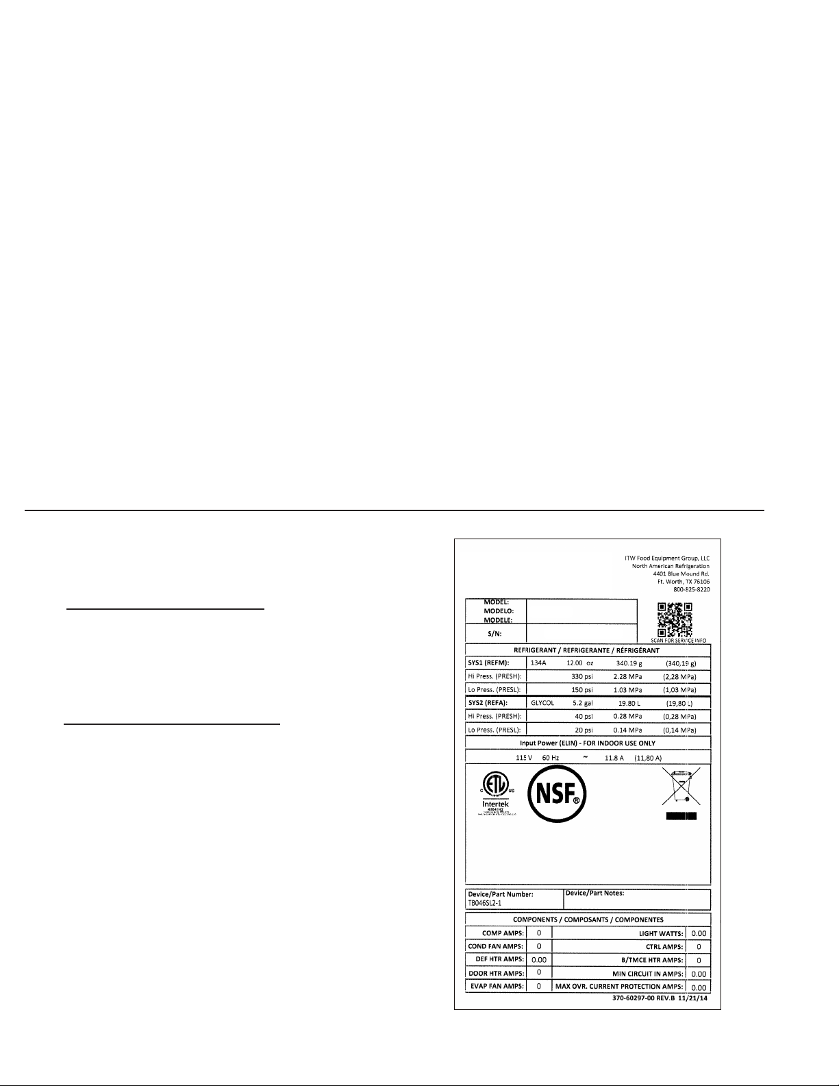
TABLE OF CONTENTS
1. THE SERIAL TAG Page 1
A) Serial Tag & Location Page 1
B) Reading The Serial Tag Page 1
2. RECEIPT INSPECTION Page 2
3. INSTALLATION Page 2
4. PRESTART CHECKS Page 3
5. OPERATION Page 3
A) Operation Page 3
B) Pan Chiller Page 3
C) Lower Storage Cabinet Page 4
D) Shutdown For Extended Period Page 4
E) Removing Food Product At Night Page 4
F) Leaving Food Product In The Unit
Throughout The Night Page 4
6. CONTROL BASICS Page 4
A) Control Basics Page 4
B) Control Panel Diagram Page 4
C) Enter The Customer Access Page 5
6. CONTROL BASICS (continued)
D) Adjusting The Thermostat Set Point Page 5
E) Adjusting The Thermostat Set Point Differential Page 5
F) Changing the Themperature Scale Page 5
G) Adjusting The Room Temperature Offset Page 5
H) Starting A Manual Defrost Cycle Page 6
I) Viewing Sensor Temperatures Page 6
J) Remote Applications Page 6
7. GENERAL CARE Page 6
A) General Care Page 6
B) Adjusting The Shelves Page 6
C) Cleaning The Condenser Page 6
D) Cleaning The Lower Storage Cabinet Page 7
E) Cleaning The Pan Chiller Page 7
8. TROUBLE SHOOTING Page 7
A) Trouble Shooting Page 8
9. SERVICE/WARRANTY INFORMATION Page 9
A) Service Information Page 9
B) Service Support Information Page 9
C) Warranty Registration Page 9
10. WARRANTIES Page 10
1. THE SERIAL TAG
1. A - SERIAL TAG & LOCATION:
The serial tag is a permanently afxed label on which is recorded
vital electrical and refrigeration data about your Traulsen product,
as well as the model and serial number. This tag is located in the
right interior compartment on all standard TB Series models.
1. B - READING THE SERIAL TAG
• Model = The model # of your Traulsen unit
• (S/N) Serial Number = The permanent ID# of your Traulsen unit
• Refrigerant SYS1= System 1 Refrigerant type used and refrigerant
charge
• Design Pressure= System 1 High and Low Pressure
• Refrigerant SYS2= System 2 Refrigerant type used and refrigerant
charge
• Design Pressure= System 2 High and Low Pressure
• Volts = Voltage
• Hz = Cycle
• Total Current = Maximum amp draw
• Min Circuit Amps = Minimum circuit ampacity
• Agency Labels = Designates agency listings
This unit is listed to UL 471, CSA 120 and NSF 7 by an approved NRTL.
TB SERIES
Page 1
Page 3
2. RECEIPT INSPECTION
3. INSTALLATION
2. A - RECEIPT INSPECTION:
Carefully inspect your Traulsen unit for damage during
delivery. If damage is detected, you should save all crating
materials and make note on the carrier’s Bill of Lading
describing the damage. A freight claim should be led
immediately. If damage is subsequently noted during or
immediately after installation, contact the respective carrier and le a freight claim. There is a ve (5) day limit to
le freight damage with the carrier. Under no condition
may a damaged unit be returned to Traulsen without rst
obtaining written permission (return authorization). You
may contact Traulsen customer care at 800-825-8220.
Some models may use R-290 (Propane)
as a refrigerant. If ammable refrigerant is present, follow
instructions as labeled on the unit. Proper care must be
taken to avoid any damage to the refrigeration system
including refrigerant tubing, condenser, evaporator coils
during handling, moving, installation and cleaning as it
may cause risk of re or explosion. If damaged, unit must
be moved to well ventilated area away from any sources
of ignition.
3. A - INSTALLATION:
Prep table models can be installed with no clearance at the back
and sides of the units.
Most units are supplied with a cord and plug, which can simply be
plugged into a dedicated appropriately sized outlet.
For those requiring hard-wiring directly to the power supply, this
should be done only by a qualied electrician. A junction box
located on back of the machine near bottom is provided for electrical eld connections. See Amp Plate inside of the refrigerated
cabinet for electrical ratings.
Some components are packed and shipped inside the lower storage cabinet to avoid damage during shipment. Remove these
items from the cabinet and remove packing materials. If unit is
equipped with shelves, cut and remove the plastic ties holding
the shelves in place.
Place cutting board on rail so that holes in cutting board line up
with pins on the counter top.
Further service and repair must be performed by qualied
refrigeration technicians familiar with applicable safety
standards for ammable refrigerants. Technicians must
use appropriate personal protective equipment and follow applicable safety precautions to avoid risk of re or
explosion.
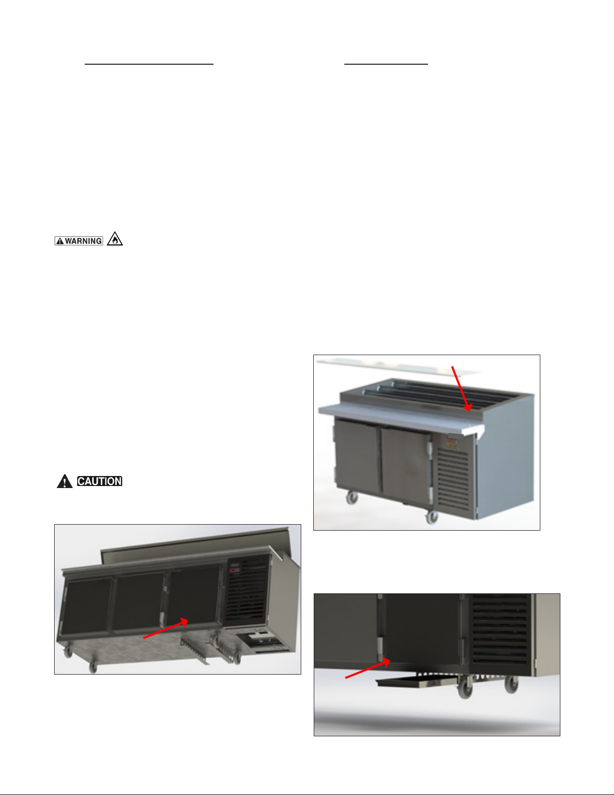
Do not damage evaporating catch pan
support brackets on the bottom of the unit when lifting the
prep table from the shipping pallet (see photo below)!
Slide evaporating catch pan over support brackets all the way
to the back of the prep table positioning it below the prep table
drain outlets.
TB SERIES
Page 2
Page 4
3. INSTALLATION (continued)
5. OPERATION
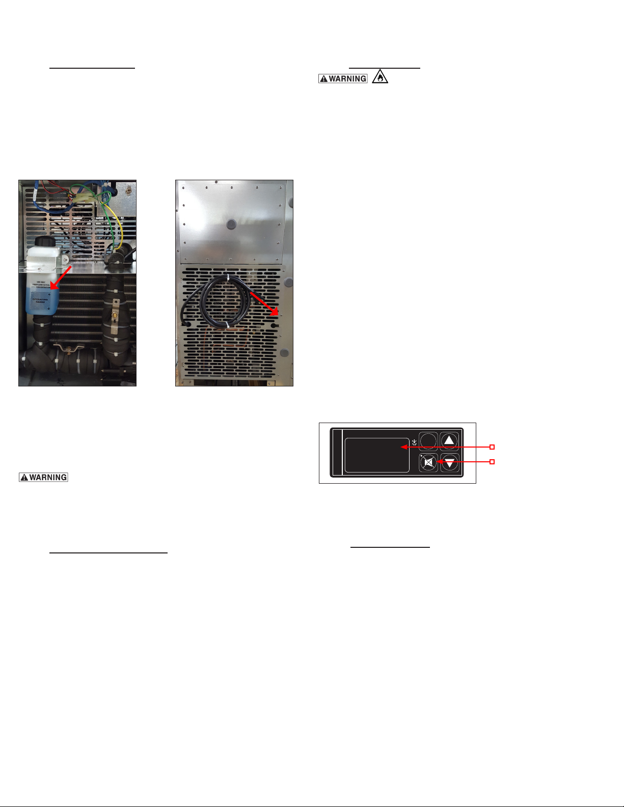
3. A - INSTALLATION: (continued):
Open the condensing compartment hinged louver door and check
the glycol level in plastic expansion tank.
A small amount of glycol may spill from tank during shipment. Prior
to startup, tank should be approximately 1/2 full. The glycol used
is a non-toxic food grade (propylene) glycol. Add 35% Propylene
Glycol if necessary.
5. A - OPERATION:
Some models may use R-290 (Propane)
as a refrigerant. Consult detailed owner’s manual available at www.traulsen.com before attempting to install or
service units with R-290 or other ammable refrigerants.
All safety precautions must be followed to avoid risk of re
or explosion. Contact Traulsen for additional information
at 800-825-8220.
Plug cordset into wall outlet (self contained models).
Open the louver door, ip the main power switch ON and
close the door. Observe the Temperature Display through
the opening in the louver door. At start-up, the readout
will ash from RHI High Glycol Temperature to CHI High
Cabinet Temperature to C35 Cabinet Air Temperature,
and to R28 Glycol Temperature this signies that the
temperatures are above normal operating range. After
the temperatures will pull down to 36°F (2°C) for the
Glycol Temperature and 41° F (5°C) for the Cabinet Air
Temperature, the readouts will stop showing RHI and
CHI error messages.
Close louver door remove rear condensing unit cover and check
if glycol ball valve is in the open position. Re-attach rear louver.
Cut zip-tie securing electrical cord and plug cord into wall socket.
GAS REFRIGERATION LINES IN CONDENSING
UNIT AREA ARE SHIPPED UNDER PRESSURE!
4. PRESTART CHECKS
4. A - PRESTART CHECKS:
Glycol Prep Tables are shipped with factory pre-set temperature
settings. Although Traulsen Glycol Prep Tables are tested at factory before shipment, there are variables that can affect cooling
performance of the unit:
• Ambient Temperature
• Humidity Level
• Air stream patterns
• Over-shelves/Heat lamps
• Product temp prior to loading into refrigerated pan chiller well.
• Surrounding equipment.
All temperature settings can be adjusted by the Customer or
Authorized Kairak Service Agent within +/- 3 °F.
Additional message power loss) will appear. Press the Alarm
Cancel Button to cancel ELE LOS message.
INTELA-TRAUL
°F °C
FREEZER
When the Glycol Temperature cools to 30°F (-1°C), the
unit is ready to go!
SET
1-LED Display
2-Alarm Cancel
Button
5. B - PAN CHILLER:
To ensure proper food temperatures are maintained in
exposed insert pans, the following conditions are recommended.
1. All food brought to line must be at 41°F (5°C) or below.
2. No direct air blowing on food product from other equipment in the kitchen (max air velocity 50 FPM/0.234 Meter/
second).
3. Room ambient temperatures of 86°F (30°C) or less
around working area of Pan Chiller.
4. All shelving mounted over insert pans (with heated
equipment above it) must be insulated. No line of sight
from radiant heat sources to insert pans.
5. Occasional stirring of certain foods may be required in
order to maintain consistent temperatures.
TB SERIES
Page 3
Page 5

6. CONTROL BASICS5. OPERATION (continued)
5. B - PAN CHILLER: (continued)
6. Some food products chill faster than others i.e., lettuce,
dried tomatoes, etc.
7. For remote refrigerators with pan chiller systems, it is
imperative that the existing refrigeration equipment to be
sized properly and in good working condition.
8. Traulsen recommends specied pans for optimum performance (see spec sheet for recommended suppliers).
5. C - LOWER STORAGE CABINET:
The lower storage cabinet is designed to maintain temperature between 33°F (0.55°C) and 40°F (4°C). If the
base is overloaded with warm food products, a certain
amount of time is required to remove heat from items
before operating temperatures can be maintained. The
system is only designed for storage of refrigerated product. Frequently opening the doors or drawers will increase
the temperature in the cabinet and will require a certain
amount of time to recover.
5. D - SHUTDOWN FOR EXTENDED PERIODS:
If the prep table and lower storage cabinet are not to
be used for an extended period of time, disconnect the
electrical power supply and open the doors (or drawers)
to the lower storage cabinet. As soon as the divided bars
and the cabinet have warmed to room temperature, wipe
out the pan chiller cavity and base interior.
5. E - REMOVING FOOD PRODUCT AT
NIGHT:
If you are storing product in the refrigerated storage
base and food needs to be removed from Pan Chiller at
night, simply close the night cover after removing food
pans. This will improve energy efciency during overnight
hours. If ALL food is removed from unit (pan chiller and
refrigerated base both empty), ip the ON/OFF switch to
shut down entire unit. To turn unit back on, ip switch ON.
5. F - LEAVING FOOD PRODUCT IN THE UNIT
THROUGHOUT THE NIGHT: (Recommended)
This unit is preset at factory and does not require periodic
shutdowns for the defrost cycle. This upgraded glycol
refrigeration system eliminates the operational burden
of removing food pans prior to the defrost period or for
overnight storage. No defrost cycle means that food can
be consistently cooled 100% of the time, day or night.
Plastic wrap should be placed over exposed food prior
TB SERIES
Page 4
6. A - CONTROL BASICS:
The product you received is equipped with a state-of-the-art patented microprocessor control, which precisely regulates operation
and provides alarms when problems occur. It is supplied from the
factory completely ready for use and requires no adjustments.
6. B - CONTROL PANEL DIAGRAM :
INTELA-TRAUL
°F °C
FREEZER
CONTROL FEATURES:
a - Water Resistant Housing
• The face of the control is water resistant to provide for protection
during cleaning.
b - Parameter/Service Levels
• See “Customer Access” on page 5.
c - Alarms (See the Troubleshooting Section for explanations)
• High/Low Cabinet Air Temperature
• High/Low Glycol Temperature
• Loss Of Power
• Sensor Failure
Defrost Error
Compressor Run Error
d - Display Features
• 3-Digit LED Display
• Fahrenheit or Celsius Temperature Scale In Use
The temperature reading will alternate every 5 seconds, displaying
SET
1-LED Display
C35 Cabinet Air Temperature and R28 Glycol Temperature.
NOTES TO THE USER:
You only have 20-30 seconds between button pushes. If you take
longer than 30 seconds, the controller will revert back to displaying
the cabinet temperature. If you enter the wrong security code, the
controller will revert back to displaying the cabinet temperature.
You can exit the parameters at any time by waiting 20-30 seconds
for the control to return to normal operation.
Page 6

6. CONTROL BASICS (continued)
6. CONTROL BASICS (continued)
6. C - ENTER THE CUSTOMER ACCESS:
Note: This is required to set any of the control parameters.
To adjust any of the control’s operating features, enter the customer access code. Use the security code 0, A, 1 combined with
the following instructions: Press the SET Button (see 3 below).
INTELA-TRAUL
°F °C
FREEZER
The display will read cus Customer Access. Press the SET But-
ton. The display will show three zeros with the left zero ashing
SET
3-SET Button
5-UP Arrow Button
4-Down Arrow Button
000. Press the SET Button. The display will show three zeros
with the center zero ashing 000. Press the ▼Arrow Button
(see 4 above) to sequence through F, E, d, C, b…etc. When you
reach “A” press the SET Button. The display will show zero, an
A, and a zero with the right zero ashing 0A0. Press the ▲
Arrow Button (see 5 above) to sequence through 1, 2, 3, 4, 5,
6, 7, 8, 9, A, b,…etc. When you reach “1” press the SET Button.
The display will read SP Thermostat Set Point. Press the SET
Button to view and again to exit. You are now ready to adjust the
control. Listed below are the available parameters in the order
they appear, using the ▼Arrow Button on the controller, you can
use either the ▲ or ▼ Arrow Button to scroll through the options.
6. D - ADJUSTING THE THERMOSTAT SET POINT:
SP Thermostat Set Point. This parameter sets the low point of
the desired pan chiller temperature range. Typically, pan chiller
will range from 27° F to 29° F (-2.7° C to -1.7° C) for this parameter setting. This parameter is preset at the factory and does not
have to be adjusted unless the customer chooses to do so. Follow the instructions to enter the Customer Access code on page
5. When the control display reads SP Thermostat Set Point,
press the SET Button. The display will then read preset 27.5
Thermostat Set Point. You can use the ▲ or ▼Arrow Button to
scroll to the next parameter or wait 30 seconds for the control to
return to normal operation.
6. E - ADJUSTING THE THERMOSTAT SET POINT
DIFFERENTIAL:
SPD Thermostat Set Point Differential. This parameter sets the
number of degrees the glycol temp will rise above set point before
the refrigeration system will cycle on. The set point differential
is set at 2.0 which will allow the glycol temperature to rise 2
degrees above Set Point setting before cycling refrigeration on.
This parameter is preset at the factory and does not have to be
adjusted unless the customer chooses to do so.
TB SERIES
Page 5
6. E - ADJUSTING THE THERMOSTAT SET
POINT DIFFERENTIAL: (continued)
Follow the instructions to enter the Customer Access code
on page 5. When the control displays SP Thermostat
Set Point, press the ▼Arrow Button until the control
display reads SPD Thermostat Set Point Differential.
Press the SET Button. Use the ▲ or ▼Arrow Button to
adjust the temperature to your desired setting. When the
display shows the temperature you want press the SET
Button. The display will then read SPDThermostat Set
Point Differential. You can use the ▲ or ▼Arrow Button
to scroll to the next parameter or wait 30 seconds for the
control to return to normal operation.
6. F - CHANGING THE TEMPERATURE
SCALE:
SCL Temperature Scale. The temperature scale deter-
mines if the temperature displayed will be in degrees
Fahrenheit
S for degrees Celsius S C. Follow the instructions to
enter the Customer Access code on page 5.
When the control displays SP Thermostat Set Point,
press the down ▼Arrow Button until the control display
reads sclTemperature Scale. Press the SET Button.
The display will start with the current setting either S f
for degrees Fahrenheit or S C for degrees Celsius. Use
the ▲ or ▼Arrow Button to toggle between the options.
When the display shows the scale you want press the
SET Button. The display will then read SCL Temperature
Scale. You can use the ▲ or ▼Arrow Button to scroll to
the next parameter or wait 30 seconds for the control to
return to normal operation.
6. G - ADJUSTING THE ROOM TEMPERATURE
OFFSET:
RO Room Temperature Offset. The room temperature
offset parameter allows a service technician or end user
the ability to have the display show a temperature that is
within three degrees of the actual temperature being read
by the Glycol Temperature sensor. This allows for continuity of reading between different temperature reading
devices. (i.e.: thermistor vs. thermocouple vs. handheld
thermometer) This parameter is preset at the factory to “0”
or no offset. Follow the instructions to enter the Customer
Access code on page 5.
When the control displays SP (thermostat set point),
press the ▼Arrow Button until the control display reads
RO Room Temperature Offset. Use the ▲ or ▼Arrow
Button to toggle between the options. When the display
shows offset you want press the SET Button. The display will then read RO Room Temperature Offset. You
Page 7

6. CONTROL BASICS (continued)
7. GENERAL CARE
6. H - STARTING A MANUAL DEFROST CYCLE:
SD Start Manual Defrost. This parameter allows a service
technician to start a defrost cycle at any time. This parameter
will override any lockout settings. Follow the instructions to
enter the Customer Access code on page 5. When the control
displays SP Thermostat Set Point, press the ▼Arrow Button
until the control display reads SD Start Manual Defrost.
Press the SET Button. The display will show OFF. Press
either the ▲ or ▼Arrow Button. The display will show On.
Press the SET Button. The defrost icon will be lit when the unit
is in defrost (see 6 below).
INTELA-TRAUL
°F °C
FREEZER
Press either the ▲ or ▼Arrow Button to scroll through the parameters, or wait 30 seconds for the control to return to normal
operation.
SET
6-Defrost Icon
6. I - VIEWING SENSOR TEMPERATURES:
These parameters allow a service technician or customer to
view the temperature of all sensors within the unit. The temperatures cannot be adjusted. Follow the instructions to enter the
Customer Access code on page 5. When the control displays
SP Thermostat Set Point, press the ▼Arrow Button until the
control display reads CB Rail Sensor or EL Cabinet Sensor
or LL Liquid Line Sensor. Press the SET Button to view the
current sensor value. Press the SET Button when done. Press
either ▲ or ▼Arrow Button to scroll through the parameters, or
wait 30 seconds for the control to return to normal operation.
FOR ALARM EXPLANATIONS SEE TROUBLE SHOOTING
PAGE 8.
6. J - REMOTE APPLICATIONS:
For remote applications consult factory. For proper operation
of remote equipment, Traulsen recommends all remote glycol
racks to provide a constant supply of 20°F (-6.7°C) glycol without any interruption in prescribed ow or capacity. The glycol
supply temperature should operate +-2° differential. Every
three (3) hours, the glycol temperature must elevate to +35°F
(1.7°C) for thirty (30) minutes to shed frost from the chiller plate
surface. After the thirty minute duration, the glycol temperature
should resume 20°F (1.7°C)+-2° operation. Flow rates for all
Traulsen equipment are noted in their respective specication
documents. Temperature and ow rate values may need to be
adjusted depending on site conditions. Contact factory before
making any adjustments.
7. A - GENERAL CARE:
Disconnect electrical power supply
before cleaning any parts of the unit. All Traulsen
gylcol equipment should be cleaned only with
warm water, mild soap and a soft cloth. Apply with
a dampened cloth and wipe in the direction of the
metal grain.
Avoid the use of strong detergents and gritty, abrasive
cleaners as they may tend to mar and scratch the
surface. Do not use cleansers containing chlorine, this
may promote metal corrosion.
Care should also be taken to avoid splashing the unit
with water, containing chlorinated cleansers, when
mopping the oor around the unit.
For stubborn odor spills, use baking soda and water
(mixed to a 1 TBSP baking soda to 1 pint water ratio).
7. B - ADJUSTING THE SHELVES:
Shelves and shelf clips are shipped with the unit. For
each shelf, insert four (4) shelf clips into the pilaster
slots at the same height. The shelf clips have a small
projection on top which holds the shelf in position and
prevents it from slipping forward. After installing shelf
clips on pilasters, place shelves on clips.
7. C - CLEANING THE CONDENSER:
Disconnect electrical power supply
before cleaning any parts of the unit.
The condensing unit coil and lter must be cleaned
regularly on self-contained models for optimal performance. The operating environment will affect the
required frequency of cleaning. However, both should
be cleaned a minimum of once every three months. Air
must be able to freely circulate through the condenser.
Unit performance and operating efciency are signicantly affected by the amount of air passing through the
condenser. Condenser ns that are clogged with dirt
and debris greatly reduce airow and removal of heat.
Failure to keep the coil ns and the air lter clean may
cause premature compressor failure, which will not be
covered by warranty. (On models that contain lters,
operating unit without lter will void warranty).
Evaporator coils should be cleaned every six (6)
months for optimal performance.
TB SERIES
Page 6
Page 8

7. GENERAL CARE (continued)
7. GENERAL CARE (continued)
7. C - CLEANING THE CONDENSER:
The evaporator coils are located in the storage cabinet
behind the coil can cover. With a Phillips head screwdriver, remove four screws and take off cover. Clean
evaporator coils with a vacuum cleaner or soft brush,
do not use a wire brush. Replace coil can cover. Reconnect electrical supply.
The air lter in all the prep tables is located in the interior rear louver door and does not require any tools for
removal (see below).
7. E - CLEANING THE PAN CHILLER:
Use water, a mild detergent and a soft cloth or sponge to clean the
pan chiller. There is one drain located in the pan chiller, provided
for condensate run-off. Drain must be cleared/cleaned regularly
for proper operation. Drains should be cleaned at a minimum of
once a month.
The drain in the plan chiller compartment is typically located above
the louvered compressor compartment. A removable screen has
been provided to prevent the drain from clogging. Clear drain of
dirt and debris so that condensate can ow freely.
7. D - CLEANING LOWER STORAGE CABINET:
Use warm, soapy water to clean lower storage cabinet and doors. NEVER use cleaners containing grit,
abrasive materials, bleach or harsh chemicals. Rinse
thoroughly and dry with a clean soft cloth. Always rub in
the same direction as the grain pattern on the stainless
steel.
To clean the inside of the lower storage cabinet,
remove wire shelves. All wire shelves are adjustable
and can be easily removed. Clean shelving in a sink. If
the shelf clips have been removed, make sure the four
clips per shelf are at same height in pilaster.
7. D - CLEANING LOWER STORAGE
CABINET: (continued)
The shelf clips have a small projection on top which
holds the shelf in position and prevents it from slip-
If drain is piped to oor sink, pan chiller may be ushed with clean
water & mild detergents. Do not leave standing water in pan chiller.
8. TROUBLE SHOOTING
8. A - TROUBLE SHOOTING:
Some models may use R-290 (Propane) as a
refrigerant. Service and repair must be performed by qualied
refrigeration technicians familiar with applicable safety standards
for ammable refrigerants. Technicians must use appropriate
personal protective equipment and follow applicable safely precautions to avoid risk of re or explosion.
Service and repair must be performed in well ventilated and
unconned area, away from any ignition sources. All system
components must be replaced with like components. Factory
recommends to use exact make and models to assure the consistent performance and to minimize the risk of possible ignition
due to incorrect parts. In case of uncertainty or parts unavailability,
contact Traulsen technical assistance at 800-825-8220.
TB SERIES
Page 7
Page 9

8. TROUBLE SHOOTING (continued)
8. A - TROUBLE SHOOTING: (continued)
SYMPTOM AND CONTROL
POSSIBLE CAUSE RECOMMENDED ACTION
ALARM
1. Unit doesn’t run? a) No power to unit.
2. Cabinet not maintaining temp.
(base cabinet warmer than 41°F/5°C)
CHI High Cabinet Air Temperature
CL N fin Condenser coil requires
cleaning
3. Cabinet not maintaining temp (base
cabinet is colder than 35°F/1.6°C)
b)Main power switch is in OFF position.
a) Base cabinet overloaded with warm
food product (food temperature above
41°F/5°C)
b) Doors open for extended periods of
time.
c) Door gasket not sealing properly
d) Air lter dirty
e) Condenser coil dirty
f) Inadequate air circulation due to product loading
g) Circulation fan faulty
h) Low refrigerant
a) No product in unit.
b) Failed sensors.
c) Stuck Evaporator Relay.
Clo Low Cabinet Temperature
4. Prep top not maintaining temp
(Chiller Rail temp warmer than
35°F/1.6°C)
a) Prep top overloaded with warm
food product (food temperature above
41°F/5°C)
Low refrigerant
RHI Glycol temperature is too high
5. Prep top not maintaining temp
(Chiller Rail temp colder than 27°F/-
2.8°C Set Point) Clo Glycol tem-
perature is too low
a) Glycol Temp. Sensor malfunction.
b) Control system components malfunc-
tioning
a) Plug in unit and check circuit breaker.
b) Remove louver panel, reach inside compressor compartment
and ip switch to ON position.
a) Remove warm food product and replace with properly chilled
product (food must be colder than 41°F/5°C before placement
into base cabinet)
b) Replace door gasket
c) Clean or replace air lter
d) Clean condenser coil
e) Shift pans/boxes to create clearance for air circulation
f) Check fan connections and replace fan if necessary
g) Call Service
h) Call Service
a) Check and replace sensor if necessary.
b) Replace evaporator relay.
a) Remove warm food product and replace with properly chilled
product (food must be colder than 41°F/5°C before placement
into prep top) Check for leaks, recharge the system
a) Check and replace sensor if necessary.
b) Check and replace control system components.
6. Compressor run time exceeds 24
hours.
7. Sensor Failures:
a) Glycol Temp. Sensor malfunction.
b) Low in refrigerant.
a) Check and replace sensor if necessary.
b) Check for leaks, recharge the system
a) Replace sensors.
sN1 Glycol temp. sensor (green)
sN2Defrost cycle termination sensor
(blue)
sN3Cabinet Air Temp.(yellow)
8. Chiller plates are coated in water
and/or ice (thin layer).
9. Defrost cycle time exceeds 120
min.
10. Chiller plates develop thick (1/8”
or more) layer of ice.
11. Pans don’t t in prep top. a) Incorrect pan model. a) Check model specs for a list of compatible pans
12. Clear water is dripping from unit. b) Catch pan is overowing or missing. a) Clean and replace catch pan in channel located underneath
13. Loss Of Power error message
ELE LOS.
a) Normal operation a) No action required. Condensation on the chiller plates will
a) Sensor malfunctioning.
b) Hot ambient environment in the
kitchen.
a) Control set below standard factory
settings.
b) Excessive compressor runtime.
a) Unit regains power after an outage or
plugged in the rst time.
occur
in most kitchen environments. Occasionally, a thin layer of ice
may develop for a short period of time.
a) Replace the sensor.
b) Block prep table from the heat source.
a) Adjust control to factory settings.
b) Clean lter and clean condenser coil if necessary.
the prep table base, ensuring that the pan reaches the drain
lines in the back of the cabinet.
a) To clear the visual text, press the Alarm Cancel Button (see
page 3 for button location).
TB SERIES
Page 8
Page 10

9. SERVICE/WARRANTY INFORMATION
9. A - SERVICE INFORMATION:
Before calling for service, please check the following:
Is the electrical cord plugged in?
Is the fuse OK or circuit breaker on?
Clean condenser coil
Is the power switch on?
If after checking the above items and the unit is still not operating properly, please contact an authorized Traulsen at:
4401 Blue Mound Road Fort Worth, TX 76106 (800) 825-8220.
Traulsen reserves the right to change specications or discontinue models without notice.
9. B - SERVICE SUPPORT INFORMATION:
To purchase replacement parts or to speak to service support for Traulsen units please contact our Ft. Worth facility by phone
at 800-825-8220 or fax to 817-740-6748 (parts) or 817-740-6757 (service).
Note: When calling for spare parts or service support, please make sure you have model and serial number of unit
available.
Model Number
Serial Number
]
9. C - WARRANTY REGISTRATION:
The warranties for your new Traulsen unit may be registered with us by contacting our Ft. Worth facility directly by phone
at 800-825-8220.
Both three year parts and labor warranty and a ve year compressor warranty are provided standard.
TB SERIES
Page 9
Page 11

10. WARRANTIES
TRAULSEN EQUIPMENT WARRANTY
v. 100215
U.S. Domestic Warranty
For sales of Traulsen refrigeration equipment (“Equipment”) within the United States, Traulsen warrants to the original
purchaser of the Equipment (“Purchaser”) that Traulsen will convey the Equipment free and clear of all liens, security
interests, and encumbrances created by, through, or under Traulsen. Traulsen further warrants that for a period of three (3)
years from the later of either (a) the date of delivery to the common carrier or (b) the date of installation (the “Domestic
Warranty Period”) but in no event, shall the Domestic Warranty Period commence later than 18 months from the date of
delivery to the common carrier unless otherwise agreed upon by the parties in writing, under normal use and given proper
installation and maintenance as determined by Traulsen, the Equipment: (a) will conform to the specifications as provided
by Traulsen (“Specifications”) and (b) will be free from substantial defects in material and workmanship.
The warranty period for compressors shall extend for an additional two (2) years beyond the Domestic Warranty Period. In
the case of a nonconforming compressor, Traulsen shall provide a replacement compressor; however all installation,
recharging, and repair costs shall be the responsibility of Purchaser. In the case of a nonconforming part, Purchaser must
return the part to Traulsen within 30 days from the date of repair. Failure to return a claimed defective part to Traulsen
within the 30 days will waive the right to the warranty claim.
Additionally, Traulsen provides a lifetime warranty on the housing of cam-lift hinges and the workflow handles. In the case
of a non-conforming housing for cam-lift hinge or workflow handle, Traulsen shall provide a replacement part; however
Purchaser shall be responsible for any other replacement costs, including but not limited to installation and labor.
The Domestic Warranty does not apply to: (a) consumable components or ordinary wear items; (b) components that are
removable without the use of tools including but not limited to gaskets, shelf pins, and light bulbs; (c) use of the Equipment
components or parts not supplied by Traulsen or specified by Traulsen in the Operator’s Manual as set forth on Traulsen’s
website; or (d) damage resulting from fire, water, burglary, accident, abuse, misuse, transit, acts of God, terrorism, power
surges, improper installation, or repairs or installation by unauthorized third parties.
For Traulsen units purchased for use with a condenser provided by a third-party, this standard warranty will apply only to
those components contained within the unit to the point of connection of the refrigeration lines leading to the third-party
condenser.
In the event of a breach of the warranties set forth above (the “Domestic Warranty”), Traulsen will, at Traulsen’s option and
as Purchaser’s sole remedy, repair or replace, including labor costs, any nonconforming Equipment, provided that (a) during
the Warranty Period Traulsen is promptly notified in writing upon discovery of the nonconformance with a detailed
explanation of any alleged deficiencies; (b) Traulsen is given a reasonable opportunity to investigate all claims; and (c)
Traulsen’s examination of any alleged defective part confirms such alleged deficiencies and that the deficiencies were not
caused by misuse, neglect, improper installation, unauthorized alteration or repair or improper testing. Traulsen reserves the
right to, at its request, require Purchaser shall ship the alleged defective part to Traulsen for inspection and confirmation of
defect. No Equipment may be returned without Traulsen’s approval.
Purchaser is solely responsible for determining if Equipment is fit for a particular purpose and suitable for Purchaser’s
application. Accordingly and due to the nature and manner of Traulsen’s Equipment, Traulsen is not responsible for the
results or consequences of use, misuse, or application of its Equipment.
THIS DOMESTIC WARRANTY SETS FORTH THE EXTENT OF TRAULSEN’S LIABILITY FOR SALES WITHIN
THE UNITED STATES. EXCEPT AS SET FORTH ABOVE, TRAULSEN MAKES NO WARRANTY OR
REPRESENTATION OF ANY KIND, EXPRESS OR IMPLIED (INCLUDING NO WARRANTY OF
MERCHANTABILITY OR FITNESS FOR ANY PARTICULAR PURPOSE). IN NO EVENT WILL TRAULSEN’S
LIABILITY IN CONNECTION WITH THE AGREEMENT OR SALE OF THE EQUIPMENT EXCEED THE
PURCHASE PRICE OF THE EQUIPMENT AS TO WHICH THE CLAIM IS MADE. IN NO EVENT SHALL
TRAULSEN BE LIABLE FOR ANY LOSS OF USE, LOSS OF PRODUCT, LOSS OF PROFIT, OR ANY OTHER
INDIRECT, INCIDENTAL, SPECIAL, OR CONSEQUENTIAL DAMAGES RESULTING FROM THIS WARRANTY
EVEN IF TRAULSEN HAS BEEN NOTIFIED OF THE POSSIBILITY OF SUCH DAMAGES.
TB SERIES
Page 10
Page 12

Quality Refrigeration
4401 Blue Mound Road Fort Worth, Texas 76106 (USA)
Phone: 800.825.8220 | Service Fax: 817.740.6757 | E-mail: service@traulsen.com | Website: traulsen.com
Form Number: TR36009 | Part Number: 375-60347-00 | Revision Date: 10-31-17
Traulsen © All Rights Reserved
 Loading...