

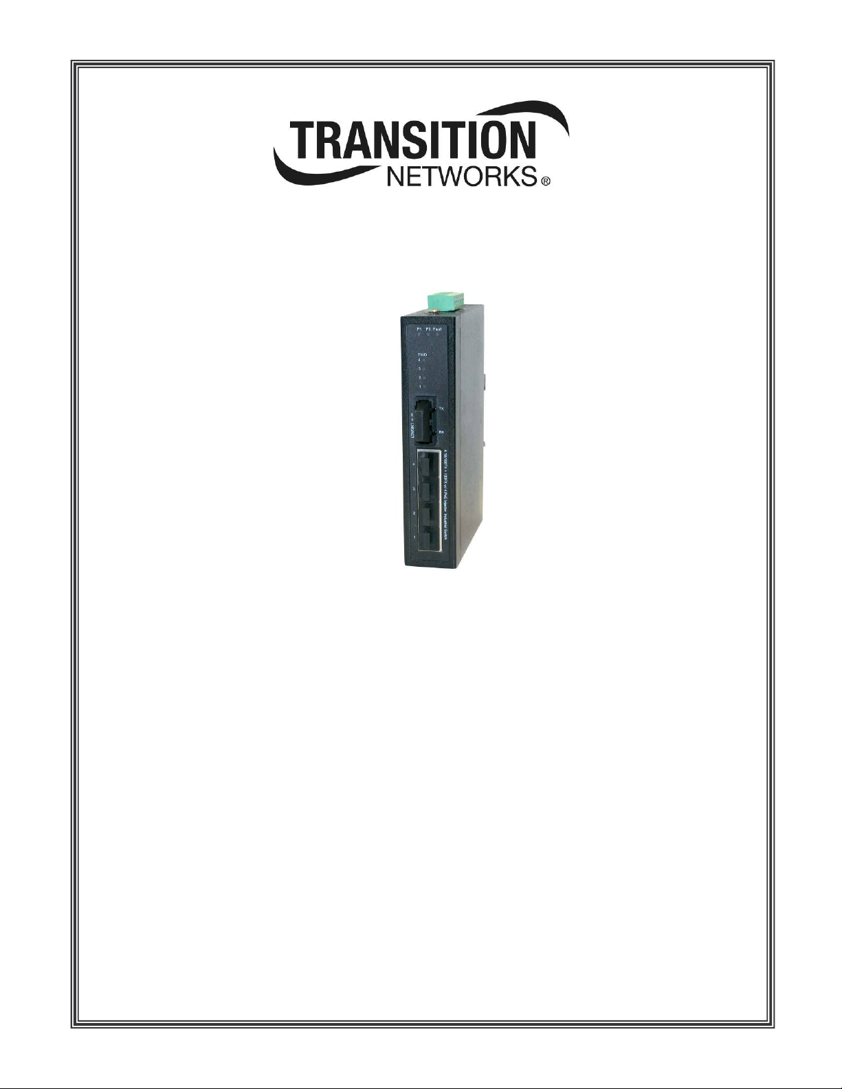
SISTP10xx-141-LR(T)
10/100Base-TX to 100Base-FX
Industrial PoE Switch
Installation Manual
Rev. A
3-Jun-2008


Transition Networks
Table of Contents
Trademark, copyright, and product classification information ......................................................................... iii
Trademark.................................................................................................................................................. iii
Copyright restrictions ................................................................................................................................. iii
FCC warning .............................................................................................................................................. iii
CE Mark ..................................................................................................................................................... iii
About this product and manual ....................................................................................................................... iv
Industrial PoE Switch ................................................................................................................................. iv
Term/usage................................................................................................................................................ iv
About this manual ...................................................................................................................................... iv
Manual structure ........................................................................................................................................ iv
Cautions and warnings .................................................................................................................................... v
Cautions and warnings................................................................................................................................ v
Cautions......................................................................................................................................................v
Warnings.................................................................................................................................................... vi
Section I ....................................................................................................................................................................1
SISTP10xx-141 Industrial PoE Switch ......................................................................................................................1
In this section ..............................................................................................................................................1
General description..........................................................................................................................................2
Overview .....................................................................................................................................................2
Features......................................................................................................................................................2
SISTP10xx-141 Industrial PoE Switch part numbers.......................................................................................3
Standard models.........................................................................................................................................3
Package contents ............................................................................................................................................4
Package contents........................................................................................................................................4
Physical description .........................................................................................................................................5
Physical dimensions....................................................................................................................................5
Front panel..................................................................................................................................................5
Bottom panel...............................................................................................................................................6
Back panel ..................................................................................................................................................6
Section II ...................................................................................................................................................................7
Installation .................................................................................................................................................................7
In this section ..............................................................................................................................................7
DIN rail mounting .............................................................................................................................................8
DIN rail clip..................................................................................................................................................8
DIN rail mounting considerations ................................................................................................................8
DIN rail mounting ........................................................................................................................................9
Wall mounting ................................................................................................................................................10
Wall mount bracket ...................................................................................................................................10
Wall mount bracket install .........................................................................................................................10
Grounding the Industrial PoE Switch .............................................................................................................11
Wiring considerations................................................................................................................................11
Industrial PoE Switch grounding ...............................................................................................................11
Connecting power to the Industrial PoE Switch .............................................................................................12
Redundant power inputs ...........................................................................................................................12
Terminal-block wiring ................................................................................................................................13
Connecting an alarm fixture ...........................................................................................................................15
Alarm relay................................................................................................................................................15
Alarm relay wiring......................................................................................................................................15
Fault indications ........................................................................................................................................16
Connecting fiber cables .................................................................................................................................17
Fiber cable installation ..............................................................................................................................17
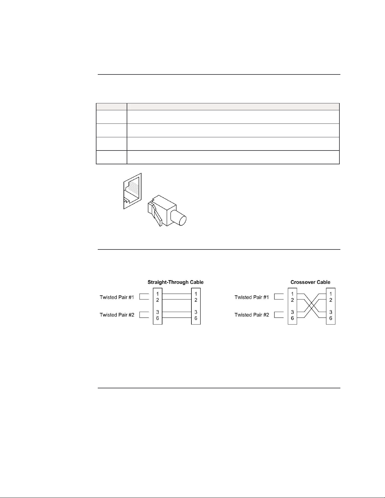
Connecting copper cables .............................................................................................................................18
Copper cable installation...........................................................................................................................18
Copper cable configuration .......................................................................................................................18
Light Emitting Diodes (LEDs).........................................................................................................................19
LEDs .........................................................................................................................................................19
Section III: ...............................................................................................................................................................20
Advanced Features .................................................................................................................................................20
Introduction ...............................................................................................................................................20
24-Hour Technical Support: 1-800-260-1312 International: 00-1-952-941-7600 i

Transition Networks SISTP10xx-141-LR(T) Industrial PoE Switch
In this section ............................................................................................................................................20
Advanced Features........................................................................................................................................21
AutoCrossTM..............................................................................................................................................21
Auto-Negotiation (IEEE 802.3u)................................................................................................................21
Pause (IEEE 802.3xy)..............................................................................................................................21
Section IV:...............................................................................................................................................................22
Cable Specifications................................................................................................................................................22
Introduction ...............................................................................................................................................22
In this section ............................................................................................................................................22
Copper (RJ-45) cable specifications ..............................................................................................................23
Copper cabling..........................................................................................................................................23
Copper cable specifications ......................................................................................................................23
RJ-45 pinouts............................................................................................................................................23
Fiber cable and optic specifications ...............................................................................................................24
Fiber cable characteristics ........................................................................................................................24
Fiber optic specifications...........................................................................................................................24
Section V:................................................................................................................................................................25
Troubleshooting.......................................................................................................................................................25
Introduction ...............................................................................................................................................25
In this section ............................................................................................................................................25
Troubleshooting problem and corrective action table ....................................................................................26
Section VI:...............................................................................................................................................................27
Contact Us, Warranty, &..........................................................................................................................................27
Compliance Information ..........................................................................................................................................27
Introduction ...............................................................................................................................................27
In this section ............................................................................................................................................27
Contact us......................................................................................................................................................28
Technical support......................................................................................................................................28
Live Web chat ...........................................................................................................................................28
Web-based training...................................................................................................................................28
E-Mail........................................................................................................................................................28
Address.....................................................................................................................................................28
Warranty ........................................................................................................................................................29
Limited lifetime warranty ...........................................................................................................................29
What the warranty does not cover.............................................................................................................29
Warranty Service.......................................................................................................................................29
Who to contact for returns.........................................................................................................................29
How and where to send the returns ..........................................................................................................29
Customer pays non-compliant return costs...............................................................................................30
Non-warranty repair costs .........................................................................................................................30
Repaired non-warranty products...............................................................................................................30
This warranty is your only remedy.............................................................................................................30
Compliance information .................................................................................................................................31
Compliances .............................................................................................................................................31
UL Listed; C-UL Listed (Canada) .............................................................................................................31
FCC Regulations.......................................................................................................................................31
Canadian Regulations...............................................................................................................................31
European Regulations...............................................................................................................................31
Appendix A:.............................................................................................................................................................33
Technical Specifications..........................................................................................................................................33
SISTP10xx-141-LR(T) specifications, notices, and warnings ........................................................................33
Notices ......................................................................................................................................................34
Warnings...................................................................................................................................................34
ii
24-Hour Technical Support: 1-800-260-1312 International: 00-1-952-941-7600

SISTP10xx-141-LR(T) Industrial PoE Switch Transition Networks
Trademark, copyright, and product classification information
Trademark
Copyright restrictions
FCC warning
All trademarks and registered trademarks are the property of their respective owners.
© 2008 Transition Networks: All rights reserved. No part of this work may be reproduced or
used in any form or by any means—graphic, electronic, or mechanical—without written
permission from Transition Networks.
Printed in the U.S.A.
This equipment has been tested and found to comply with the limits for class A devices,
pursuant to part 15 of FCC rules. These limits are designed to provide reasonable
protection against harmful interference in a commercial installation. This equipment
generates, uses, and radiates radio frequency energy; therefore, if it is not installed and
used in accordance with the instructions in this document, could cause harmful
interference to radio communications. Operation of this equipment in a residential area
is likely to cause harmful interference; the user will be required to correct the interference
at the user’s own expense.
CE Mark
CE Marking (European Conformity): This is a Class A product. In a domestic
environment, this product could cause radio interference; as a result, the user may be
required to take adequate preventative measures.
24-Hour Technical Support: 1-800-260-1312 International: 00-1-952-941-7600
iii

Transition Networks SISTP10xx-141-LR(T) Industrial PoE Switch
About this product and manual
Industrial PoE Switch
Term/usage
About this manual
Manual structure
The SISTP10xx-141-LR(T) unmanaged Industrial PoE Switch provides (4) 10/100Base-TX
(RJ-45) copper ports with Power over Ethernet injection and a 100Base-FX fiber connection
with a fixed optical transceiver. These switches are hardened devices designed to reliably
operate in harsh environments such as those found on factory floors, outdoor enclosures or
other hazardous environments.
In this manual, the term “Industrial PoE Switch” (first letter upper case) refers to the
SISTP10xx-141-LR(T) 10/100Base-TX to 100Base-FX Industrial PoE Switch.
This manual provides instructions on how to install, configure, and operate the
SISTP10xx-141-LR(T) 10/100Base-TX to 100Base-FX Industrial PoE Switch.
This manual has a beginning table of contents; also, at the beginning of each section there is
a table of contents. As you traverse the manual, note the side headings. These side
headings make it easier to find specific information. The manual sections are as follows:
Section Description
I Industrial PoE Switch general description, ordering information, package
contents and physical features/description
II Installation and operation of the Industrial PoE Switch
III Advanced features
IV Cable Specifications
V Troubleshooting
VI Contacting Transition Networks, product warranty and product compliance
information
Appendix A Presents product specifications, notices, and warnings
iv
24-Hour Technical Support: 1-800-260-1312 International: 00-1-952-941-7600

SISTP10xx-141-LR(T) Industrial PoE Switch Transition Networks
Cautions and warnings
Cautions and warnings
Cautions
Make sure that you read and understand all content identified by these two symbols:
Cautions and warnings appear here and throughout this manual where appropriate. Failure to
read and understand the information identified by the “caution” and “warning” symbols could
result in poor equipment performance, damage to equipment, or injury to persons.
Cautions indicate the possibility of damage to equipment.
CAUTION
Make sure that the Industrial PoE Switch is mounted with proper space around it for
ventilation (heat dissipation). Failure to observe this caution could result in damage to the
Industrial PoE Switch.
CAUTION
Please exercise caution when using power tools. Do not install this unit in damp or wet
locations, or in close proximity to very hot surfaces. Failure to observe this caution could
result in damage to the Industrial PoE Switch and cables.
CAUTION
Only qualified persons should install the Industrial PoE Switch. Failure to observe this
caution could result in poor performance or damage to the Industrial PoE Switch.
CAUTION
Install the Industrial PoE Switch in an environment where the temperature range will not
exceed the stated environmental specifications for the particular model being installed.
Failure to observe this caution could result in permanent damage to the Industrial PoE
Switch.
CAUTION
DO NOT install the Industrial PoE Switch in areas where strong electromagnetic fields
(EMF) exist. Failure to observe this caution could result in poor Industrial PoE Switch
performance and data corruption.
CAUTION
The Industrial PoE Switch must be mounted to a well-grounded surface. Failure to
observe this caution could result in EMI problems.
CAUTION
When connecting DC power wires to the terminal-block plug, pay close attention to the
polarity markings shown near the terminal block of the Industrial PoE Switch. Failure to
observe this caution could result in damage to the equipment.
CAUTION
This is a Class A product. In a residential environment, this product could cause radio
interference in which case the user may be required to take adequate corrective
measures.
Continued on next page
24-Hour Technical Support: 1-800-260-1312 International: 00-1-952-941-7600
v

Transition Networks SISTP10xx-141-LR(T) Industrial PoE Switch
Cautions and warnings, continued
Warnings
Warnings indicate the possibility of injury to persons.
WARNING
Be sure to disconnect power before installing and wiring the Industrial PoE Switch.
Failure to observe this warning could result in an electrical shock.
WARNING
Fiber optics: Visible and invisible laser radiation when open: DO NOT stare into the
beam, or directly view the beam with optical instruments. Failure to observe this warning
could result in an eye injury or blindness.
WARNING
Use of controls, adjustments or the performance of procedures other than those
specified herein may result in hazardous radiation exposure.
vi
24-Hour Technical Support: 1-800-260-1312 International: 00-1-952-941-7600

In this section
Section I
SISTP10xx-141 Industrial PoE Switch
These are the topics:
Topic See Page
General description 2
SISTP10xx-141 Industrial PoE Switch model numbers 3
Package Contents 4
Physical Description 5

Transition Networks SISTP10xx-141-LR(T) Industrial PoE Switch
General description
Overview
Features
The SISTP10xx-141 unmanaged Industrial PoE Switch can help eliminate EMI or RFI issues
and help to overcome distance limitations with copper-based cabling by providing a fiber
interface to transport data from copper-based industrial networking and communication
devices over fiber optic cabling. In addition, these PoE switches are industrial hardened
Power Sourcing Equipment (PSE) and are fully compatible with Powered Devices (PD) that
comply with the IEEE802.3afTM Power over Ethernet standard.
Each Industrial PoE Switch can connect to either 10Base-T or 100Base-TX copper ports and
provides a 100Base-FX fiber optic connection. In addition, the four RJ-45 ports also provide
power to Data Terminal Equipment (DTE) Power Devices (PD) over unshielded twisted pair
cabling. Multiple fiber optic connector options are offered as well as two distinct operating
temperature ranges:
- Standard: -10°C to +50°C (14°F to +122°F)
- Extended: -40°C to +65°C (-40°F to +149°F)
The SISTP10xx-141 Industrial PoE Switch has the following features:
• Auto-Negotiation
• AutoCrossTM
• IEEE802.3af Power over Ethernet compliant
• 4-port integrated POE injector with full 15.4 Watts per port on data pairs
• Under-current detection and over current protection [re-settable fuse]
• Dual, redundant auto-sensing 48VDC inputs with reverse polarity protection
• Dry Contact Relay alarm output for failure of primary or redundant power input
• IEEE 802.3x flow control support
Flow control on full-duplex
Back pressure on half-duplex
• 1K MAC address table
• Full wire-speed with 1Gbps backplane switching fabric
• DIN-Rail mounting bracket (installed)
• Wall mount brackets included
• IP30 protection metal enclosure
• Lifetime Warranty
2
24-Hour Technical Support: 1-800-260-1312 International: 00-1-952-941-7600
SISTP10xx-141-LR(T) Industrial PoE Switch Transition Networks
SISTP10xx-141 Industrial PoE Switch part numbers
Standard models
The part numbers shown in Tables 1 and 2 perform as described in this manual.
Table 1: Industrial PoE Switch Part Numbers
Standard Operating Temperature (-10°C to +50°C)
Part Number Ports 1-4: 10/100Base-TX Port 5: 100Base-FX
SISTP1011-141-LR RJ-45
100 m (328ft)
SISTP1013-141-LR RJ-45
100 m (328ft)
SISTP1014-141-LR RJ-45
100 m (328ft)
Table 2: Industrial PoE Switch Part Numbers
Extended Operating Temperature (-40°C to +65°C)
Part Number Ports 1-4: 10/100Base-TX Port 5: 100Base-FX
SISTP1011-141-LRT RJ-45
100 m (328ft)
SISTP1013-141-LRT RJ-45
100 m (328ft)
SISTP1014-141-LRT RJ-45
100 m (328ft)
Note: The distances for ports 1 and 2 listed in Tables 1 and 2 are typical maximum
distances; the physical characteristics of the network will affect the actual distances.
ST, 1300 nm multimode
2 km (1.2miles)
SC, 1300 nm multimode
2 km (1.2 miles)
SC, 1310 nm single mode
20 km (12.4 miles)
ST, 1300 nm multimode
2 km (1.2miles)
SC, 1300 nm multimode
2 km (1.2 miles)
SC, 1310 nm single mode
20 km (12.4 miles)
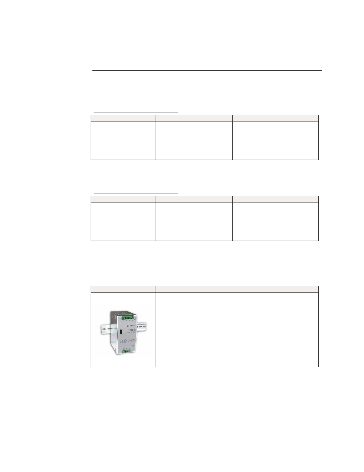
Table 3: Optional Accessories (sold separately)
Part Number Description
25080
Industrial DIN Rail Power Supply 120W
- Universal AC input voltage range (switch selectable)
88 ~ 132VAC/176 ~ 264VAC
- 48VDC, 2.5A output
- Operating temperature range: -10°C to +60°C
- Short circuit/Over load/Over voltage/Over temperature protection
- Cooling by free air convection – no fan
- UL 508(industrial control equipment)approved
- LED indicator for power on
- 100% full load burn-in test
- Dimensions: 65mm W x 125mm H x 100mm D
- Lifetime warranty
24-Hour Technical Support: 1-800-260-1312 International: 00-1-952-941-7600
3

Transition Networks SISTP10xx-141-LR(T) Industrial PoE Switch
Package contents
Package contents
Quantity Description
1 10/100Base-TX to 100Base-FX Industrial PoE Switch
1 DIN-Rail mounting bracket (installed)
2 Wall mount brackets
8 Screws (for attaching wall-mount bracket)
1 Installation manual CD
Compare the package contents of your industrial PoE Switch with the standard checklist
above. If any item is damaged or missing, please contact Transition Networks Technical
Support.
4
24-Hour Technical Support: 1-800-260-1312 International: 00-1-952-941-7600
SISTP10xx-141-LR(T) Industrial PoE Switch Transition Networks
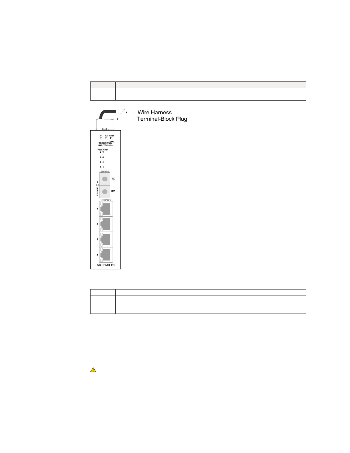
Full Duplex/Collision
UTP p
ort 1-4 LED
PoE Power FWD
UTP
ports 1-4
LED
Link/Activity Fiber port 5 LED
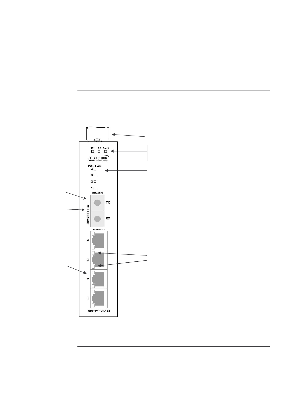
Physical description
Physical dimensions
Front panel
Width: 1.2” [30mm]
Height: 5.5” [140mm]
Depth: 3.7” [95mm]
The front panel of the Industrial PoE Switch is shown in Figure 1 with corresponding
descriptions listed below:
Terminal block - power inputs / relay outputs
Fault LED
Secondary power input 2 LED
Primary power input 1 LED
100Base-FX Fiber Port
(SC shown)
10/100Base-TX
UTP ports (RJ-45)
w/ PoE injector
Link/Activity UTP port 1-4 LED
24-Hour Technical Support: 1-800-260-1312 International: 00-1-952-941-7600
Figure 1: SISTP10xx-141-LR(T) Industrial PoE Switch (Front View)
Continued on next page
5

Transition Networks SISTP10xx-141-LR(T) Industrial PoE Switch
Physical description, continued
Bottom panel
The top view of the Industrial PoE Switch is shown in Figure 2 with corresponding descriptions
listed below:
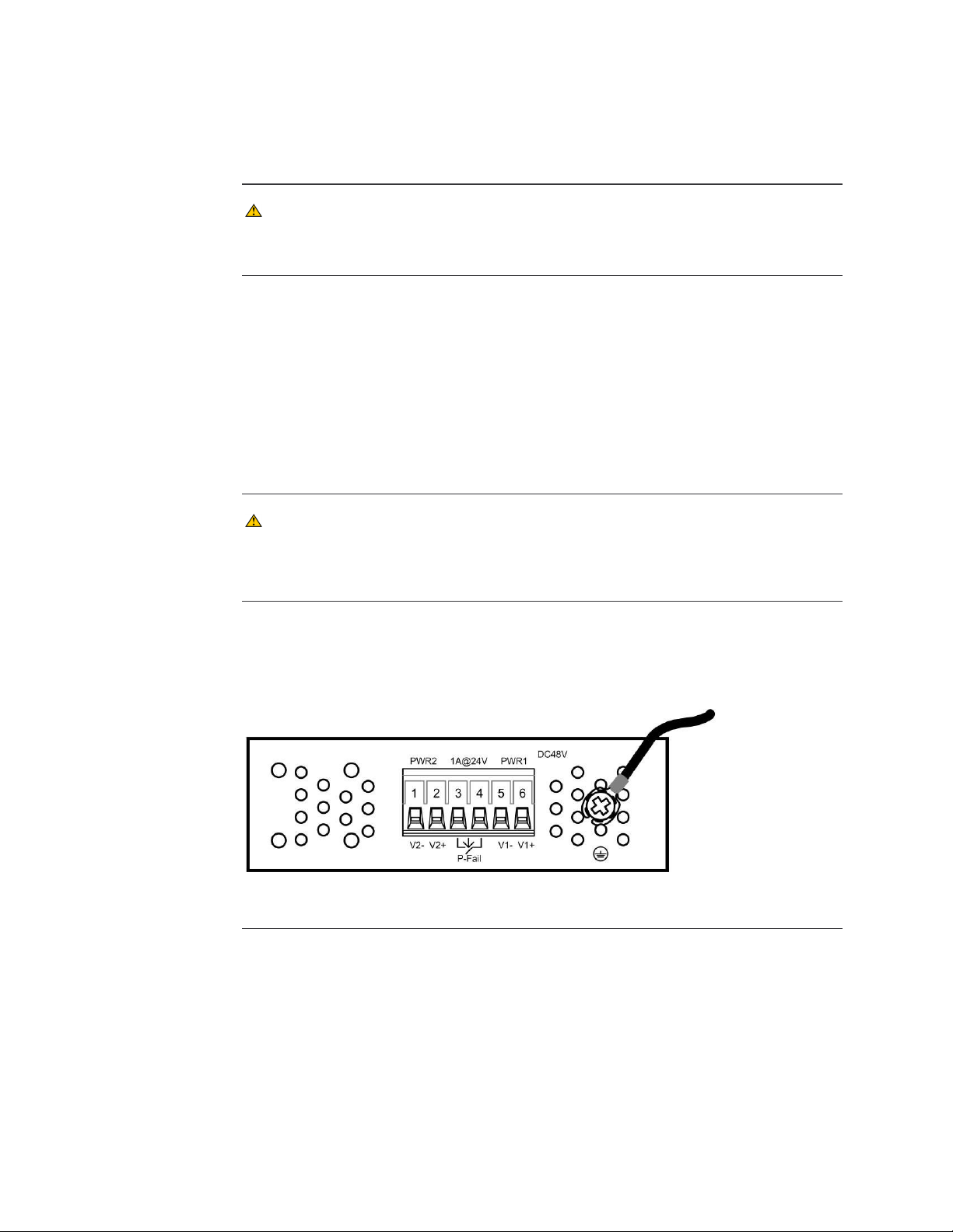
6-position terminal block
Grounding Screw
Secondary power input terminals (2)
Figure 2: SISTP10xx-141-LR(T) Industrial PoE Switch (Top View)
Contact relay
output terminals (2)
Primary power input terminals (2)
Back panel
The back view of the Industrial PoE Switch is shown in Figure 3 with corresponding
descriptions listed below:
DIN Rail Clip
(installed)
Metal spring
Screws (3)
Figure 3: SISTP10xx-141-LR(T) Industrial PoE Switch (Back View)
6
24-Hour Technical Support: 1-800-260-1312 International: 00-1-952-941-7600

In this section
Section II
Installation
These are the topics:
Topic See Page
DIN rail mounting 8
Wall mounting 10
Grounding the Industrial PoE Switch 11
Connecting power to the Industrial PoE Switch 12
Connecting an alarm fixture 15
Connecting fiber cable 17
Connecting copper cable 18
Light Emitting Diodes (LEDs) 19

Transition Networks SISTP10xx-141-LR(T) Industrial PoE Switch
DIN rail mounting
DIN rail clip
The Industrial PoE Switch includes an aluminum DIN Rail Clip attached to the rear panel.
Verify the clip is attached and oriented as pictured in Figure 4 below.
DIN Rail Clip
(installed)
Metal spring
Screws (3)
DIN rail mounting considerations
Figure 4: Mounted DIN Rail Clip
Consider the following before mounting the DIN rail to a surface and attaching the Industrial
PoE Switch:
• The surface must support at least 450g (1.0 lbs) for the Industrial PoE Switch.
• Do not place heavy objects on the Industrial PoE Switch.
CAUTION
Mount the Industrial PoE Switch with proper spacing around it for ventilation (heat
dissipation). Failure to observe this caution could result in damage to the Industrial PoE
Switch.
CAUTION
Please exercise caution when using power tools. Do not install this unit in damp or wet
locations, or in close proximity to very hot surfaces. Failure to observe this caution could
result in damage to the Industrial PoE Switch and cables.
Continued on next page
8
24-Hour Technical Support: 1-800-260-1312 International: 00-1-952-941-7600

SISTP10xx-141-LR(T) Industrial PoE Switch Transition Networks
DIN rail mounting, continued
DIN rail mounting
To mount the Industrial PoE Switch to the DIN rail, see Figure 5 and do the following:
Step Action
1. Align and then position DIN-Rail-clip spring to the top of the DIN rail as shown in
Figure 5, step (a).
2. Press DOWN on the Industrial PoE Switch and then IN to snap it into place on the
DIN Rail. See Figure 5, step (b).
Figure 5: Industrial PoE Switch Mounting to DIN Rail
To remove the Industrial PoE Switch from the DIN rail, reverse the steps above.
24-Hour Technical Support: 1-800-260-1312 International: 00-1-952-941-7600
9

Transition Networks SISTP10xx-141-LR(T) Industrial PoE Switch
Wall mounting
Wall mount bracket
Wall mount bracket install
The Industrial PoE Switch includes wall mount brackets and screws in the contents of the
shipping package. The wall mount brackets can be attached to the top and bottom panels of
the Industrial PoE Switch to enable mounting to a vertical surface such as the wall of an
enclosure. Locate the brackets (2) and screws (8) and follow the steps below to install the
brackets on the Industrial PoE Switch.
To install the wall mount brackets to the Industrial PoE Switch, see Figure 6 and do the
following:
Step Action
1. Remove existing screws (3) and DIN-Rail bracket from rear of Industrial PoE
Switch.
2. Locate wall mount brackets (2) and screws (8) from Industrial PoE Switch
packaging.
3. Place brackets in correct orientation as shown and insert and tighten screws to
secure bracket to the top and bottom of Industrial PoE Switch.
4. Mount assembled device to a wall per locally accepted practices for anchoring
and securing. (Wall mount screws not included.)
Locate wall mount
brackets and screws
2
Remove screws and
DIN rail bracket
1
3
Screw brackets onto top and
bottom of Industrial Switch
Figure 6: Installing wall mount brackets to Industrial PoE Switch
10
24-Hour Technical Support: 1-800-260-1312 International: 00-1-952-941-7600
SISTP10xx-141-LR(T) Industrial PoE Switch Transition Networks
Grounding the Industrial PoE Switch
CAUTION
Be sure to disconnect the Industrial PoE Switch from the DC power source before
installing and wiring the device.
Wiring considerations
The following wiring considerations are recommended:
• Signal lines must not be directly connected to outdoor wiring.
• Use separate paths or conduits to route wiring for power and device data cables. To avoid
interference, wires with different signal characteristics route separately. If power wiring and
device data cables must cross make sure that the wires are perpendicular at the
intersection point.
• Use the type of signal transmitted through a wire to determine which wires should be kept
separate. The rule of thumb is wiring that shares similar electrical characteristics can be
bundled together.
• Keep input and output wiring separated.
CAUTION
The Industrial PoE Switch is intended to be grounded to a well-grounded mounting
surface such as a metal plate. Install the grounding wire prior to connecting any other
device to the Industrial PoE Switch.
Industrial PoE Switch grounding
Grounding the Industrial PoE Switch helps limit the effects of noise due to electromagnetic
interference (EMI) via proper grounding. Always run the ground connection from the ground
screw to a grounding surface before connecting the Industrial PoE Switch to a DC power
source. See Figure 7.
Figure 7: Industrial PoE Switch Ground Screw (Top Panel)
24-Hour Technical Support: 1-800-260-1312 International: 00-1-952-941-7600
11

Transition Networks SISTP10xx-141-LR(T) Industrial PoE Switch
Power Input 2
Power Input 1
Connecting power to the Industrial PoE Switch
Redundant power inputs
The Industrial PoE Switch has dual (redundant) power inputs capable of auto-sensing the
input voltage, while providing over current protection and reverse polarity protection.
The dual power inputs can be connected simultaneously to live DC power sources. See Figure
8. If one power source fails, the other live source acts as a backup, and automatically supplies
the Industrial PoE Switch with power.
12
Figure 8: Redundant Power Connections
IMPORTANT
• Power is supplied through an external 48 VDC power source. Check the Technical
Specification section for details about the DC power input voltage.
• The Industrial PoE Switch does not include a power switch; therefore, plugging a wired and
active terminal-block plug into its terminal block will immediately power ON the unit.
CAUTION
Before connecting the Industrial PoE Switch to a DC power source, ensure the power
source is stable.
CAUTION
This device is intended to be supplied by a listed power source marked LPS or Limited
Power Source, provided with a connector for field wiring terminal.
CAUTION
This device is designed for operation with a safety extra-low voltage (SELV) in
compliance with IEC950 / EN60950 / VDE0805 and in compliance with the low
voltage directive 73/23/EEC and 93/68/EEC.
Continued on next page
24-Hour Technical Support: 1-800-260-1312 International: 00-1-952-941-7600

SISTP10xx-141-LR(T) Industrial PoE Switch Transition Networks
Connecting power to the Industrial PoE Switch, continued
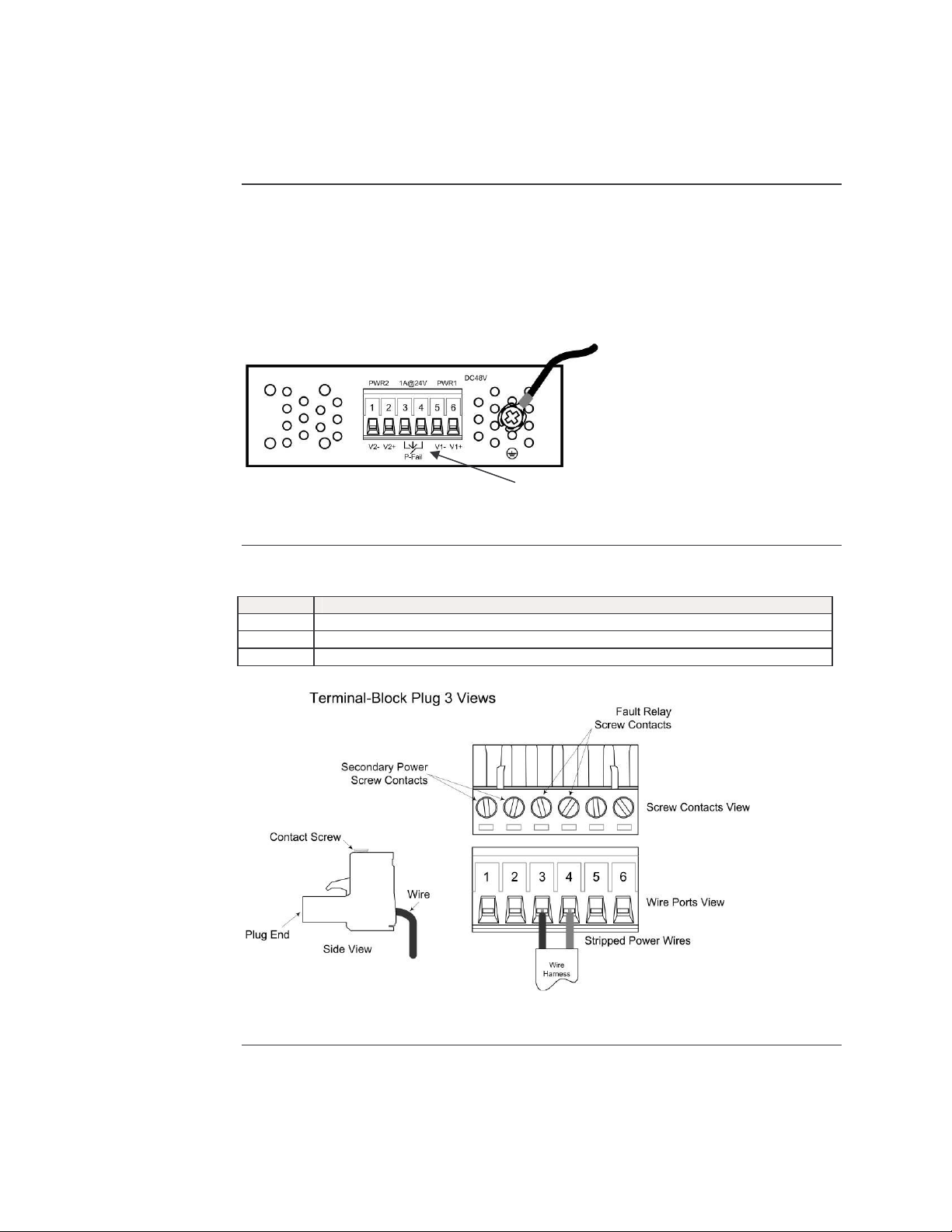
Note: The terminal block can accept 12 – 24 AWG wire for power and alarm relay inputs.
Terminal-block wiring
To wire the 6-position terminal block for redundant power, do the following:
Note: The 6-position terminal-block plug is constructed (keyed) to mate with the Industrial
PoE Switch terminal block. When wiring the plug for power, use the polarity markings
next to the terminal block and on top of the plug to ensure proper connection.
Step Action
1. Turn the external power source OFF.
2. Strip the power wires as required.
3. Insert one stripped power wire into the terminal block plug. Observe polarity.
See Figure 9.
4. Secure the wire using a flathead screwdriver by tightening the contact screw.
See Figure 9.
5. Repeat Steps 3 and 4 until all wires are installed and secured.
Figure 9: 6-Position Terminal-Block (Primary/Redundant Power Wiring)
Continued on next page
24-Hour Technical Support: 1-800-260-1312 International: 00-1-952-941-7600
13
Transition Networks SISTP10xx-141-LR(T) Industrial PoE Switch
Connecting power to the Industrial PoE Switch, continued
Terminal-block wiring (continued)
Step Action
6.
Insert the terminal block plug into the Industrial PoE Switch’s terminal block, as
shown in Figure 10.
14
Figure 10: Wired Terminal Block Plug Inserted Into Industrial PoE Switch
7.
8.
Note: An external AC/DC power supply is not included with the Industrial PoE Switch.
CAUTION
Make sure that the DC power source is stable and clean.
Turn ON the power source and the PWR LED should turn ON along with PWR 1
LED and/or PWR 2 LED, depending on whether one or both power supplies are
connected and turned ON.
Transition Networks offers an accessory power supply that can be purchased
separately, if required. Please see optional accessories in the general information
section of this manual for ordering information.
The operating temperature of the Industrial PoE Switch, when used in conjunction with
an AC/DC power supply will be limited to the lesser operating temperature range of
either device.
For example: SISTP10xx-141-LRT (-40ºC to +65ºC operating temp) used
with 25080 (-10ºC to +60ºC operating temp)
Operating temp for combination is -10ºC to +60ºC
24-Hour Technical Support: 1-800-260-1312 International: 00-1-952-941-7600
SISTP10xx-141-LR(T) Industrial PoE Switch Transition Networks
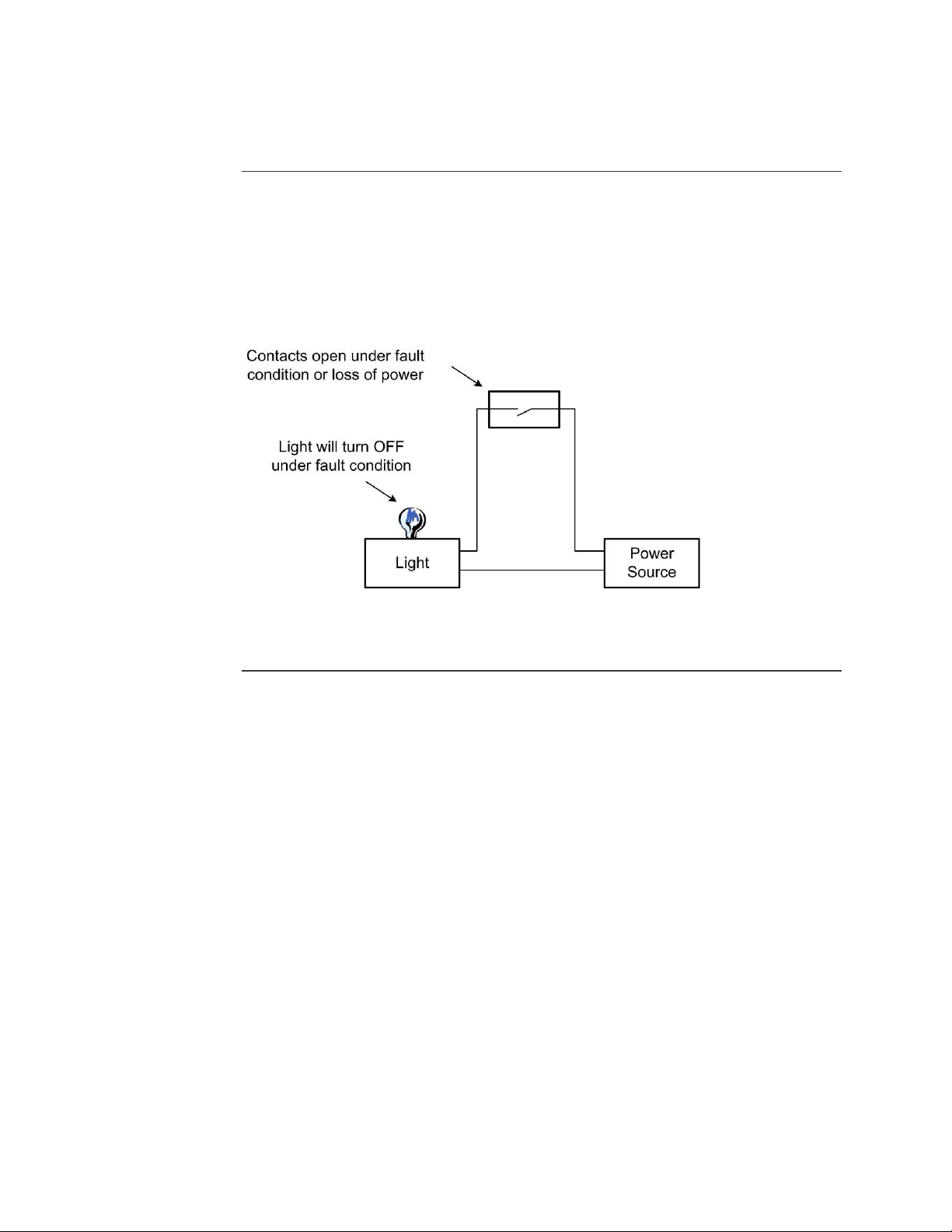
Alarm Relay Contacts
Connecting an alarm fixture
Alarm relay
The Industrial PoE Switch has dry relay contacts for connecting an external alarm fixture.
Located on the green terminal block on the top panel, the relay has “normally open” contacts
that can be wired to form a circuit for triggering an external alarm when a fault occurs (light or
audible alarm). See Figure 11.
Note: Normally open contacts are contacts that form an open circuit when there is a loss of
power to the device or when a fault occurs. Once power is applied to the Industrial
PoE Switch, the contacts will be closed and current will flow through the contacts.
Figure 11: Alarm Relay Contacts
Alarm relay wiring
To wire an alarm to the relay contacts, do the following:
Step Action
1. Verify that the external power source is turned OFF.
2. Strip the wires as required.
3. Wire the alarm relay as shown in Figure 12.
Figure 12: Alarm Relay Wiring
Continued on next page
24-Hour Technical Support: 1-800-260-1312 International: 00-1-952-941-7600
15
Transition Networks SISTP10xx-141-LR(T) Industrial PoE Switch
Connecting an alarm fixture, continued
Fault indications
Wire the relay contacts to any warning light or audible alarm in the control room as shown in
Figure 13. When a fault occurs, the relay contacts open, stopping the flow of current through
the contact circuit. This will disable the external alarm or turn OFF a light, indicating a fault.
An alarm will occur under the following conditions:
• Power failure to either of the Industrial PoE Switch power inputs:
o Power wires are disconnected, power source malfunction
o Input power is something other than 48VDC
Figure 13: Alarm Relay Contacts
16
24-Hour Technical Support: 1-800-260-1312 International: 00-1-952-941-7600
SISTP10xx-141-LR(T) Industrial PoE Switch Transition Networks
Connecting fiber cables
Fiber cable installation
When connecting fiber cables to the 100BASE-FX port on the Industrial PoE Switch, make
sure the correct type is used: ST or SC.
To install the fiber cables, do the following:
Step Action
1. Remove and keep the fiber-port protective dust cover(s).
Note: When not connected to a fiber cable, keep the protective cover(s) on the optical ports
to protect the optics and keep dust and debris from entering the optical interface.
2. Check that the fiber connectors on the fiber-optic cabling are clean. If necessary,
clean the fiber connectors using locally accepted cleaning procedures.
Note: Dirty fiber connectors on fiber optic cables will impair light transmission quality
through the cable and lead to degraded performance on the port.
3. Connect the fiber cable as shown in Figure 14.
Figure 14: Fiber Cable Connections
4. Check the corresponding fiber port LED on the Industrial PoE Switch to verify the
connection—LNK/ACT LED should be lit.
Warning
• Visible and invisible laser radiation when open: DO NOT stare into the beam, or
directly view the beam with optical instruments. Failure to observe this warning could
result in an eye injury.
• Use of controls, adjustments or the performance of procedures other than those
specified herein may result in hazardous radiation exposure.
24-Hour Technical Support: 1-800-260-1312 International: 00-1-952-941-7600
17
Transition Networks SISTP10xx-141-LR(T) Industrial PoE Switch
Connecting copper cables
Copper cable installation
To connect the copper cable to the Industrial PoE Switch and other equipment, do the
following:
Step Action
1. Locate or build 10Base-T or 100Base-TX compliant copper cables with male, RJ45 connectors installed at both ends.
2. Connect the RJ-45 connector at one end of the cable to the RJ-45 port on
the Industrial PoE Switch. See Figure 15 below.
3. Connect the RJ-45 connector at the other end of the cable to the RJ-45
port on the other device (switch, workstation, PLC, etc.).
4. Check the copper port LED on the Industrial PoE Switch to verify the
connection—LNK/ACT LED should be lit.
Copper cable configuration
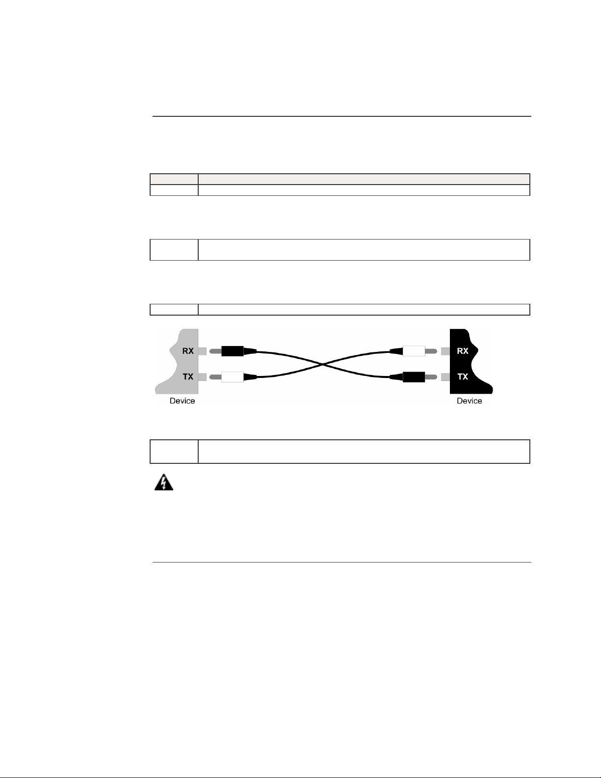
Figure 15: Copper Cable Installation
Either a straight-through or cross-over cable may be used. See Figure 16.
Figure 16: Straight-Through and Crossover Cables
Note: The AutoCrossTM feature determines the characteristics of the cable connection and
automatically configures the unit to link up, regardless of the cable configuration,
allowing either straight-through (MDI) or crossover (MDI-X) cables to be used.
(Requires no operator intervention.). See Advanced Features section for more
information.
18
24-Hour Technical Support: 1-800-260-1312 International: 00-1-952-941-7600

SISTP10xx-141-LR(T) Industrial PoE Switch Transition Networks
Light Emitting Diodes (LEDs)
LEDs
The Industrial PoE Switch has LED indicators located on its front panel. The LEDs present ata-glance network status, and provide real-time connectivity information. Figure 17 shows the
LEDs and a chart that explains the function of each.
LED Description
P1 Green = input power present on PWR1
input
P2 Green = input power present on PWR2
input
FAULT Red = Loss of either power input
LNK/ACT
(Fiber port)
PWR FWD 1-4 Green = PoE power being supplied to
LNK/ACT
(UTP port)
[upper LED]
Full Duplex /
Collision
(UTP port)
[lower LED]
Green = fiber link
Green (blinking) = fiber port is receiving
link pulses or data from a
100Base-FX compliant port
powered device (PD)
Off = No PoE power being output on
port
Green = UTP link
Green (blinking) = UTP port is receiving
link pulses or data from a
10/100Base-TX compliant port
Yellow = Full duplex link
Yellow (blinking) = collisions occurring
Off = half duplex or no link
Figure 17: LEDs and Description Chart
24-Hour Technical Support: 1-800-260-1312 International: 00-1-952-941-7600
19

Introduction
In this section
Section III:
Advanced Features
This section provides an explanation of the advanced features on the Industrial PoE Switch.
These are the topics:
Topic See Page
AutoCrossTM 21
Auto-Negotiation 21
Pause 21

SISTP10xx-141-LR(T) Industrial PoE Switch Transition Networks
Advanced Features
AutoCrossTM
AutoCrossTM automatically detects and configures the twisted pair port on the converter to the
correct MDI or MDI-X configuration allowing either straight-through (MDI) or crossover (MDI-X)
cables to be used – see figure 18. No user intervention is required.
* Eliminates an entire category of troubleshooting
* No need to identify cable type; straight-through or crossover
* No user intervention required to determine correct button / switch settings
Figure 18: Straight-Through and Crossover Cables
Auto-Negotiation
(IEEE 802.3u)
Pause (IEEE 802.3xy)
Auto-Negotiation allows devices to perform automatic configuration to achieve the best
possible mode of operation over a link. The Industrial PoE Switch will broadcast its speed
(10Mbps, 100Mbps) and duplex (half, full) capabilities to other devices and negotiate the best
mode of operation between the two devices.
* No user intervention required to determine best mode of operation
* Optimal link established automatically
* Quick and easy installation
Note: If the Industrial PoE Switch is connected to a non-negotiating device over the copper
link, it will default to 10Mb/s speed, half duplex mode.
PAUSE signaling is an IEEE feature that is used to temporarily suspend data transmission
between two devices in the event that one of the devices becomes overwhelmed. In the event
that a device needs some time to clear network congestion, it will send out a PAUSE signal to
the other end device, which will then wait a pre-determined amount of time before retransmitting the data. Transition's converters will pass PAUSE signaling unhindered; ensuring
that the message is delivered to the end device.
* PAUSE enabled devices allowed to work properly
* Prevents loss of valuable data transmission
* Reduces bottlenecks and allows for efficient use of network devices
Note: PAUSE signaling is not standardized over fiber media. Transition's Industrial PoE
Switches will communicate this signaling over fiber between the switches to pass this
signaling on to the other end device.
24-Hour Technical Support: 1-800-260-1312 International: 00-1-952-941-7600
21

Transition Networks SISTP10xx-141-LR(T) Industrial PoE Switch
Section IV:
Cable Specifications
Introduction
In this section
This section provides copper and fiber cable specifications.
These are the topics:
Topic See Page
UTP cable specifications 23
Fiber cable and optic specifications 24
22
24-Hour Technical Support: 1-800-260-1312 International: 00-1-952-941-7600

SISTP10xx-141-LR(T) Industrial PoE Switch Transition Networks
Copper (RJ-45) cable specifications
Copper cabling
Shielded twisted-pair (STP) or unshielded twisted-pair (UTP) cabling may be used and can be
configured as either Straight-through or crossover – see figure 19.
Figure 19: Straight-Through and Crossover Cables
Note: The AutoCrossTM feature determines the characteristics of the cable connection and
automatically configures the unit to link up, regardless of the cable configuration,
allowing either straight-through (MDI) or crossover (MDI-X) cables to be used.
(Requires no operator intervention.). See Advanced Features section for more
information.
Copper cable specifications
RJ-45 pinouts
Wire category: Category 5 (minimum)
Attenuation: 22.0 dB /100m @ 100 MHz
Gauge: 24 to 22 AWG
Maximum cable distance: 100 meters (328 ft)
Figure 20 shows the RJ-45 connector pin assignment chart for 10Base-T or 100Base-TX.
No MDI Signal Name MDI-X Signal Name
1 Receive Data + (RD+) Transmit Data + (TD+)
2 Receive Data - (RD-) Transmit Data - (TD-)
3 Transmit Data + (TD+) Receive Data + (RD+)
6 Transmit Data - (TD-) Receive Data - (RD-)
Figure 20: RJ-45 Connector Pin Assignment Chart
Note: The Industrial PoE Switch is configured as a MDI-X device.
24-Hour Technical Support: 1-800-260-1312 International: 00-1-952-941-7600
23

Transition Networks SISTP10xx-141-LR(T) Industrial PoE Switch
Fiber cable and optic specifications
Fiber cable characteristics
Fiber optic specifications
Cable physical characteristics must meet or exceed IEEE 802.3™ specifications.
Parameter Specification
Bit Error Rate: <10-9
Single mode fiber: 9 µm
Multimode fiber: 62.5/125 µm
Multimode fiber: 100/140, 85/140, 50/125 µm
The following shows the fiber optic specification:
Fiber Cable Specifications
SISTP1011-141-LR(T)
Fiber-optic transmitter power:
Fiber-optic receiver sensitivity:
Link budget:
SISTP1013-141-LR(T)
Fiber-optic transmitter power:
Fiber-optic receiver sensitivity:
Link budget:
SISTP1014-141-LR(T)
Fiber-optic transmitter power:
Fiber-optic receiver sensitivity:
Link budget:
1300 nm multimode
min: -20.0 dBm max: -14.0 dBm
min: -31.0 dBm max: 0.0 dBm
11.0dB
1300 nm multimode
min: -20.0 dBm max: -14.0 dBm
min: -31.0 dBm max: 0.0 dBm
11.0dB
1310 nm single mode
min: -15.0 dBm max: -8.0 dBm
min: -32.0 dBm max: -5.0 dBm
17.0 dB
Note: The fiber optic transmitters on this device meet Class I Laser safety requirements per
IEC-825/CDRH standards and comply with 21CFR1040.10 and 21CFR1040.11.
24
24-Hour Technical Support: 1-800-260-1312 International: 00-1-952-941-7600

SISTP10xx-141-LR(T) Industrial PoE Switch Transition Networks
Section V:
Troubleshooting
Introduction
In this section
This section provides basic troubleshooting information for the Industrial PoE Switch via a
problem and corrective action table. The problems are stated in the problem column and the
action(s) to take for the problem is stated in the corrective action column. If the corrective
measures listed do not correct the problem, contact our 24-Hour Technical Support
department at 1-800-260-1312, International: 00-1-952-941-7600.
These are the topics:
Topic See Page
Troubleshooting problem and corrective action table 26
24-Hour Technical Support: 1-800-260-1312 International: 00-1-952-941-7600
25

Transition Networks SISTP10xx-141-LR(T) Industrial PoE Switch
Troubleshooting problem and corrective action table
Problem Potential Cause Potential Solution
Industrial PoE Switch does
not power up
No link or activity on the
UTP port
No link or activity on the
Fiber port
Alarm contacts not working
• Is the wired terminal-block plug fully
inserted into the Industrial PoE
Switch?
• Is the power LED lit?
• Is the power LED lit?
• Is the UTP cable properly installed
at both ends?
• Is the power LED lit?
• Is the Fiber cable properly installed
at both ends?
• Is the wired terminal-block plug fully
inserted into the Industrial PoE
Switch?
• Is the alarm circuit wired for
normally-open contacts?
• Wire and insert the terminal-block plug
into the Industrial PoE Switch’s terminal
block – See pages 12-14
• Check that DC power is at the
recommended levels.
• Contact Technical Support.
US/Canada: 1-800-260-1312,
International: 00-1-952-941-7600
• Check that the power is turned ON.
• Verify that the cable at both ends is
properly inserted into the UTP port
• Check that the power is turned ON.
• Verify that the cable at both ends is
properly inserted into the fiber port
• Wire alarm contacts and circuit and
insert the terminal-block plug into the
Industrial PoE Switch’s terminal block –
See page 15
• Check that alarm circuit is wired
correctly – See page 16
• Contact Technical Support.
US/Canada: 1-800-260-1312,
International: 00-1-952-941-7600
26
24-Hour Technical Support: 1-800-260-1312 International: 00-1-952-941-7600

Introduction
In this section
Section VI:
Contact Us, Warranty, &
Compliance Information
This section explains how to contact Transition Networks via Phone, fax, email, and direct
mail. It also explains:
• What the warranty covers
• Who to contact to return product
• How and where to return the product
• Industry standards compliance
These are the topics:
Topic See Page
Contact us 28
Warranty 29
Compliance information 31

Transition Networks SISTP10xx-141-LR(T) Industrial PoE Switch
Contact us
Technical support
Live Web chat
Web-based training
Technical Support is available 24 hours a day.
United States: 1-800-260-1312
International: 00-1-952-941-7600
Chat live via the Web with a Transition Networks Technical Support Specialist.
Log onto www.transition.com and click the Transition Now link.
Transition Networks provides 8-10 seminars per month via live web-based training.
Log onto www.transition.com and click the Learning Center link.
Ask a question anytime by sending an e-mail message to our technical support staff at:
techsupport@transition.com
Address
Transition Networks
10900 Red Circle Drive
Minnetonka, MN 55343, U.S.A.
Telephone: 952-941-7600
Toll free U.S.A & Canada: 800-526-9267
Fax: 952-941-2322
28
24-Hour Technical Support: 1-800-260-1312 International: 00-1-952-941-7600

SISTP10xx-141-LR(T) Industrial PoE Switch Transition Networks
Warranty
Limited lifetime warranty
What the warranty does not cover
Warranty Service
Effective for products shipped May 1, 1999 and after, every Transition Networks’ labeled
product will be free from defects in material and workmanship for its lifetime. This warranty
covers the original user only and is not transferable.
This warranty does not cover damage from accident, acts of God, neglect, contamination,
misuse or abnormal conditions of operation or handling, including over-voltage failures caused
by use outside the product’s specified rating, or normal wear and tear of mechanical
components. If the user is unsure of the proper means of installing or using the equipment,
contact Transition Networks’ free technical support services.
Transition Networks will at its option:
• Repair the defective product to functional specification at no charge
• Replace the product with an equivalent functional product
• Refund the purchase price of a defective product
Who to contact for returns
How and where to send the returns
To return a defective product for warranty coverage, contact Transition Networks’ technical
support department for a return authorization number (RAN). Transition’s technical support
department can be reached through any of the following means:
Technical Support is available 24 hours a day:
• Tel: 800-260-1312 x 200 or 952-941-7600 x 200
• Fax: 952-941-2322
• Email: techsupport@transition.com
• Live web chat: Transition Now
• Voicemail: 800-260-1312 x 579 or 952-941-7600 x 579
• All messages will be answered within one hour
Send the defective product postage and insurance prepaid to the following address:
CSI Material Management Center
c/o Transition Networks
10900 Red Circle Drive
Minnetonka, MN 55343 U.S.A.
Attn: RETURNS DEPT: Credit Return Authorization (CRA)# or Return Material Authorization
(RMA) # ___________
Failure to protect the product during shipping may void this warranty. The return authorization
number must be written on the outside of the carton to ensure its acceptance. We cannot
accept delivery of any equipment sent to us without a CRA or RMA number.
Continued on next page
24-Hour Technical Support: 1-800-260-1312 International: 00-1-952-941-7600
29

Transition Networks SISTP10xx-141-LR(T) Industrial PoE Switch
Warranty, continued
Customer pays non-compliant return costs
Non-warranty repair costs
Repaired nonwarranty
products
The customer must pay the non-compliant product(s) return transportation cost to Transition
Networks for evaluation of said product(s) for repair or replacement. Transition Networks will
pay for shipping the repaired or replaced in-warranty product(s) back to the customer (any and
all customs charges, tariffs, or/and taxes are the customer’s responsibility).
Before making any non-warranty repair, Transition Networks requires a $200 charge, plus
actual shipping costs to and from the customer. If the repair is greater than $200, an estimate
is issued to the customer for authorization of repair. If no authorization is obtained, or the
product is deemed not repairable, Transition Networks will retain the $200 service charge and
return the product to the customer not repaired.
Non-warranted products repaired by Transition Networks for a fee will carry a 180-day limited
warranty. All warranty claims are subject to the restrictions and conventions set forth by this
document.
Transition Networks reserves the right to charge for all testing and shipping incurred, if after
testing, a return is classified as “No Problem Found.”
This warranty is your only remedy
This warranty is your only remedy. No other warranties, such as fitness for a particular
purpose, are expressed or implied. Transition Networks is not liable for any special, indirect,
incidental or consequential damages or losses, including loss of data, arising from any cause
or theory. Authorized resellers are not authorized to extend any different warranty on
Transition Networks’ behalf.
30
24-Hour Technical Support: 1-800-260-1312 International: 00-1-952-941-7600

SISTP10xx-141-LR(T) Industrial PoE Switch Transition Networks
Compliance information
Compliances
UL Listed;
C-UL Listed
(Canada)
FCC Regulations
Canadian Regulations
CISPR22/EN5022 Class A + EN55024; EN60950 Class A; FCC Class A; CE Mark
The following part numbers are UL Listed: SISTP1011-141-LR, SISTP1011-141-LRT,
SISTP1013-141-LR, SISTP1013-141-LRT, SISTP1014-141-LR, SISTP1014-141-LRT.
This equipment has been tested and found to comply with the limits for a Class A digital
device, pursuant to part 15 of the FCC rules. These limits are designed to provide reasonable
protection against harmful interference when the equipment is operated in a commercial
environment. This equipment generates, uses, and can radiate radio frequency energy and, if
not installed and used in accordance with the instruction manual, may cause harmful
interference to radio communications. Operation of this equipment in a residential area is
likely to cause harmful interference, in which case the user will be required to correct the
interference at the user’s own expense.
This digital apparatus does not exceed the Class A limits for radio noise for digital apparatus
set out on the radio interference regulations of the Canadian Department of Communications.
Le présent appareil numérique n'émet pas de bruits radioélectriques dépassant les limites
applicables aux appareils numériques de la Class A prescrites dans le Règlement sur le
brouillage radioélectrique édicté par le ministère des Communications du Canada.
European Regulations
CUATION:
This is a Class A product. In a domestic environment, this product could cause radio
interference in which case the user may be required to take adequate corrective measures.
Achtung !
Dieses ist ein Gerät der Funkstörgrenzwertklasse A. In Wohnbereichen können bei Betrieb
dieses Gerätes Rundfunkstörungen auftreten. In diesem Fäll ist der Benutzer für
Gegenmaßnahmen verantwortlich.
Attention !
Ceci est un produit de Classe A. Dans un environnent domestique, ce produit risque de créer
des interférences radioélectriques, il appartiendra alors à l'utilisateur de prende les measures
spécifiques appropriées.
24-Hour Technical Support: 1-800-260-1312 International: 00-1-952-941-7600
31

Transition Networks SISTP10xx-141-LR(T) Industrial PoE Switch
European
Regulations,
(continued)
In accordance with European Union Directive 2002/96/EC of the European Parliament and of
the Council of 27 January 2003, Transition Networks will accept post usage returns
of this product for proper disposal. The contact information for this activity can be
found in the ‘Contact Us’ portion of this document.
CAUTION: RJ connectors are NOT INTENDED FOR CONNECTION TO THE
PUBLIC TELEPHONE NETWORK. Failure to observe this caution could result in
damage to the public telephone network.
Der Anschluss dieses Gerätes an ein öffentlickes Telekommunikationsnetz in den EGMitgliedstaaten verstösst gegen die jeweligen einzelstaatlichen Gesetze zur Anwendung der
Richtlinie 91/263/EWG zur Angleichung der Rechtsvorschriften der Mitgliedstaaten über
Telekommunikationsendeinrichtungen einschliesslich der gegenseitigen Anerkennung ihrer
Konformität.
32
24-Hour Technical Support: 1-800-260-1312 International: 00-1-952-941-7600

Appendix A:
Technical Specifications
SISTP10xx-141-LR(T) specifications, notices, and warnings
Parameter Description
Standards IEEE 802.3™, IEEE 802.3ab, IEEE 802.3u,
IEEE 802.3x, IEEE 802.3af
Regulatory Compliance for
Emissions
Safety Compliance UL 60950; cUL; CE/EN60950-1
EMI Compliance EN61000-4-2; EN61000-4-3; EN61000-4-4;
Environmental Compliance IEC60068-2-32 (Free fall)
Ports (1) fiber port single mode/multi-mode
Fiber Optic Specifications
Max Distance
Max Data Rate Fiber: 100 Mb/s
Signals TxD, RxD, CTS, RTS, DTR, DSR, RI, DCD, GND
MAC address table 1k MAC addresses
Power Consumption 4.6 watts (w/o PoE); 66 watts (w/PoE)
Ingress Protection IP30
MTBF (MIL-HDBK-217F) 443,154 hours
Input Power 48 VDC, 0.1A-1.4A; dual, redundant auto-sensing
Dimensions
Weight
Shipping weight
Standard Operating Temperature
(-LR models only)
Extended Operating Temperature
(-LRT models only)
Storage Temperature
Operating Humidity
Warranty Lifetime
CISPR/EN55022 Class A; FCC Class A; CE Mark;
EN61000-4-5; EN61000-4-6; EN61000-4-8;
EN61000-4-11; EN61000-4-12; EN61000-6-2;
EN61000-6-4
IEC60068-2-27 (Shock)
IEC60068-2-6 (Vibration)
(4) RJ-45 port
1300 nm multimode
min: -20.0 dBm max: -14.0 dBm
min: -31.0 dBm max: 0.0 dBm
11.0dB
1310 nm single mode
min: -15.0 dBm max: -8.0 dBm
min: -32.0 dBm max: -5.0 dBm
17.0 dB
Fiber (fixed): up to 20km (12.4 miles)
Copper: up to 100 meters (328 ft.)
Copper: 10Mb/s or 100Mb/s
inputs with reverse polarity and overload current
protection
Width: 1.2" [30 mm]
Depth: 3.7" [95 mm]
Height: 5.5" [140 mm]
0.45 kg (1.0 lbs)
0.59 kg (1.3 lbs)
-10ºC to +50ºC (32 ºF to 140ºF)
-40ºC to +65ºC (-40 ºF to 167ºF)
-40ºC to +85ºC (-40 ºF to 185ºF)
5% to 95% (non-condensing)
Transition Networks SISTP10xx-141-LR(T) Industrial PoE Switch
SISTP10xx-141-LR(T) specifications, notices, and warnings, continued
Notices
Warnings
• The information in this user’s guide is subject to change. For the most up-to-date
information on the SISTP10xx-141-LR(T) Industrial PoE Switch, please refer to the user’s
guide on-line at: www.transition.com.
• Product is certified by the manufacturer to comply with DHHS Rule 21/CFR, Subchapter J
applicable at the date of manufacture.
• IMPORTANT Copper based media ports: e.g., Twisted Pair (TP) Ethernet, USB, RS-232,
RS422, RS485, DS1, DS3, Video Coax, etc., are intended to be connected to intra-building
(inside plant) link segments that are not subject to lightening transients or power faults.
Copper based media ports: e.g., Twisted Pair (TP) Ethernet, USB, RS-232, RS-422, RS485, DS1, DS3, Video Coax, etc., are NOT to be connected to inter-building (outside plant)
link segments that are subject to lightening transients or power faults. Failure to observe
this caution could result in damage to equipment.
WARNING: Visible and invisible laser radiation when open: Do not stare into the beam
or view the beam directly with optical instruments. Failure to observe this warning could
result in an eye injury or blindness.
WARNING: Use of controls, adjustments or the performance of procedures other than
those specified herein may result in hazardous radiation exposure.
34
24-Hour Technical Support: 1-800-260-1312 International: 00-1-952-941-7600
 Loading...