

SAPTF33xx-1xx
3
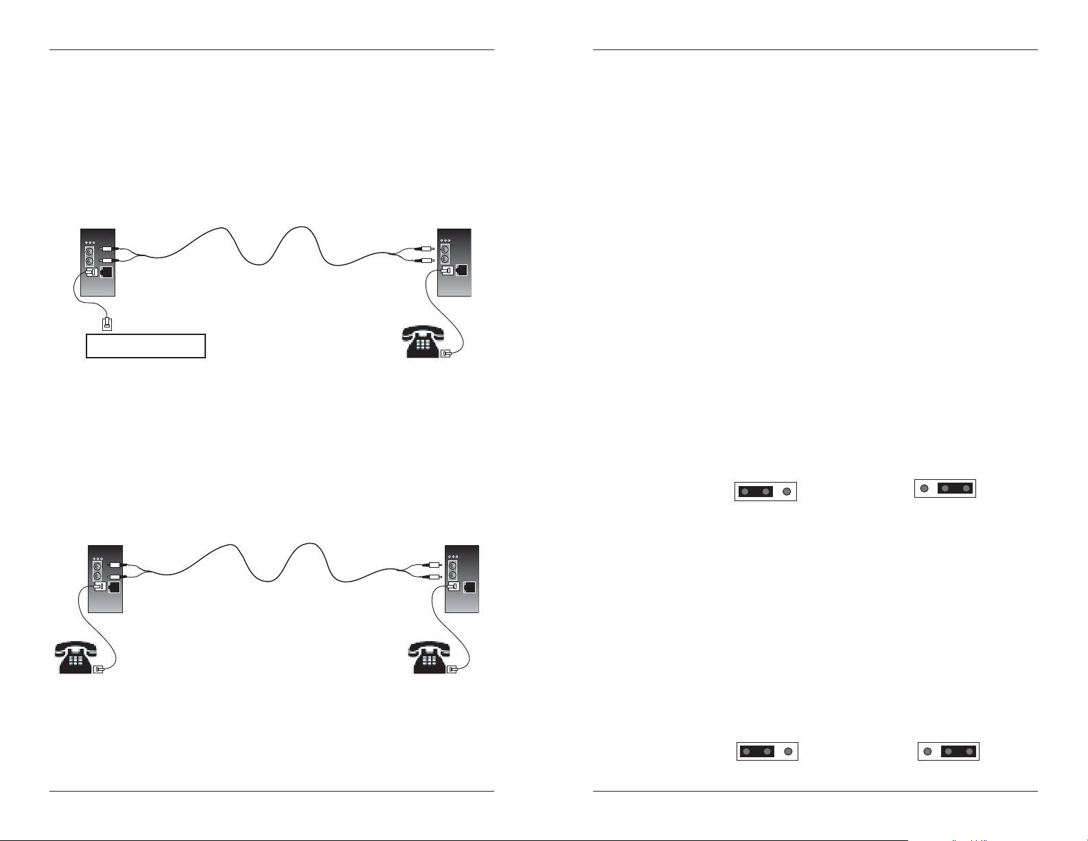
SAPTF33xx-1xx in the Network
Standard Configuration
One Unit A device (SAPTF33xx-100) and one Unit B device (SAPTF33xx-110)
are required for the standard configuration. The Unit A device is connected to
the Central Office (CO) while the Unit B device is connected to a telephone
device.
SAPTF33xx-100
Unit A -- Emulates
the telephone device
Central Office (CO)
Automatic Ring-Down Configuration
Automatic Ring Down (ARD) is a dedicated, point-to-point voice system. When
one telephone is taken off-hook, the other telephone rings, without the need to
dial. Two Unit B devices (SAPTF33xx-110), connected via the fiber ports, are
required for this mode of operation; with a telephone device at each end.
SAPTF33xx-110
Unit B -- Emulates the
Central Office (CO)
SAPTF33xx-110
Unit B -- Emulates the
Central Office (CO)
SAPTF33xx-110
Unit B -- Emulates the
Central Office (CO)
Installation
CAUTION: Wear a grounding device and observe electrostatic discharge
precautions when setting the jumpers. Failure to observe this caution could
result in damage to, and subsequent failure of, the media converter.
Setting the Jumpers
1. Using a small screwdriver, remove the screws that secure the cover to the
media converter and carefully remove the cover.
2. Locate the jumpers on the circuit board.
3. Using small needle-nosed pliers or similar device, move the jumper to the
desired position. (Refer to the drawings below.)
4. Carefully replace the cover on the media converter and replace the
screws to secure the cover.
Standard / Automatic Ring-Down
The jumper labeled “JP1” is used to switch between the Standard or Automatic
Ring-Down configuration and is located on the top circuit board of Unit B
(SAPTF33xx-110).
The drawing below illustrates the jumper settings.
• Set jumper JP1 on the Unit B device to the Standard setting when
using the Standard configuration (described on page 4).
• Set jumper JP1 on both Unit B devices to the Automatic Ring-Down
setting when using the Automatic Ring-Down configuration
(described on page 4).
JP1
1
Standard
JP1
13
Automatic
Ring-Down
US / EU Telephone Regulation
The jumper labeled “US EU” is used to switch between the US or EU
telephone configuration and is located on the top circuit board of Unit A
(SAPTF33xx-100). This feature is required to comply with the EU TBR21
telephone regulation. The jumper has been set at the factory to the US setting
as the default.
The drawing below illustrates the jumper settings.
• Set jumper “US EU” on the Unit A device to the US setting if the
device is to be used with US-based telephone systems.
• Set jumper “US EU” on the Unit A device to the EU setting if the
device is to be used with European-based telephone systems.
US EU US EU
US Setting EU Setting
4
24-hour Technical Support: 1-800-260-1312 -- International: 00-1-952-941-7600
techsupport@transition.com Click the “Transition Now” link for a live Web chat.
5
g
SAPTF33xx-1xx
g
e
Installation -- Continued
Grounding the Media Converter
The SAPTF33xx-1xx single-slot chassis comes equipped with grounding lugs
Installation -- Continued
Installing the Cable -- Standard Configuration
NOTE: Unit B MUST be configured for Standard Configuration (see page 4).
located on the back panel. They require a grounding conductor wire
terminated with a two-hole, compression-type, grounding connector. The
grounding wire -- which must be a copper conductor -- is not included with
the chassis and must be provided by the customer/installer.
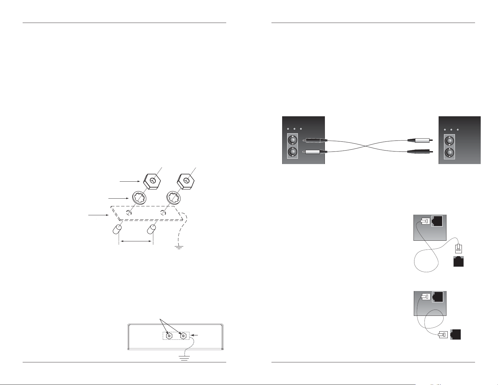
Fiber
1. Locate or build fiber cable with male, two-stranded TX to RX connectors
installed at both ends.
The electrical conducting path from the single-slot chassis must:
• Flow via the grounding lugs to the common bonding network (CBN).
• Be of sufficiently low impedance to conduct fault currents likely to be
imposed on the media converter, and
2. Connect the fiber cables to Unit A (SAPTF33xx-100) as described:
• Connect the male TX cable connector to the female TX port.
• Connect the male RX cable connector to the female RX port.
PWR
ACT
SDF
Unit A
Unit B
ACT
SDF
PWR
• Enable proper operation of any over-current protection devices.
The conductor must be fastened to the grounding lugs with the enclosed anti-
TX RX
TX RX
rotation star-washers and lug-nut fasteners. The applied torque required to the
connector lug-nut fasteners is specified by the connector’s manufacturer.
3. Connect the fiber cables to Unit B (SAPTF33xx-110) as described:
Lug nuts (included)
Star washer (included)
Two-hole, compression-type
grounding connector
(not included)
Grounding lugs
(6-32, 1/8" diam.)
12 AWG copper wir
(not included)
• Connect the male TX cable connector to the female RX port.
• Connect the male RX cable connector to the female TX port.
Copper
1. Locate or build copper cables with male, RJ11C connectors installed at both ends.
2. Connect the copper cables to Unit A
Unit A
(SAPTF33xx-100) as described:
3/4-inch
spacin
To properly ground the SAPTF33xx-1xx single-slot chassis:
1. Obtain one (1) grounding conductor (12 AWG copper wire gauge or
larger) with a two-hole, compression-type, grounding connector.
2. Attach the grounding conductor to the converter by placing the two-hole
connector onto the grounding lugs and fasten with the enclosed lockwashers / lug-nuts at the proper torque (per the manufacturer’s
specification).
3. Attach the opposite end of the
rounding lugs
grounding conductor to the
6
(CBN).
24-hour Technical Support: 1-800-260-1312 -- International: 00-1-952-941-7600
common bonding network
grounding
connector
and wire
earth ground
techsupport@transition.com Click the “Transition Now” link for a live Web chat.
• Connect the RJ-11C connector at one
end of the cable to the RJ-11C port on
Unit A.
• Connect the RJ-11C connector at the
other end of the cable to the RJ-11C port
on the Central Office.
3. Connect the copper cables to Unit B
(SAPTF33xx-110) as described:
• Connect the RJ-11C connector at one
end of the cable to the RJ-11C port on
Unit B.
• Connect the RJ-11C connector at the
other end of the cable to the RJ-11C port
on the telephone device.
Connect to the
RJ-11C port on the
Central Office.
Unit B
Connect to the
RJ-11C port on the
telephone device.
7

SAPTF33xx-1xx
T
Installation -- Continued
Installing the Cable -- Automatic Ring-Down Configuration
NOTE: Both Unit B’s MUST be configured for Automatic Ring-Down (see page 4).
Fiber
1. Locate or build fiber cable with male, two-stranded TX to RX connectors
installed at both ends.
2. Connect the fiber cables to the first Unit B (SAPTF33xx-110) as described:
• Connect the male TX cable connector to the female TX port.
• Connect the male RX cable connector to the female RX port.
PWR
ACT
SDF
TX RX
Unit B Unit B
3. Connect the fiber cables to the second Unit B (SAPTF33xx-110) as
described:
• Connect the male TX cable connector to the female RX port.
• Connect the male RX cable connector to the female TX port.
Copper
1. Locate or build copper cables with male, RJ-11C connectors installed at
both ends.
2. Connect the copper cables to both Unit B’s (SAPTF33xx-110) as described:
• Connect the RJ-11C connector at one end
of the cable to the RJ-11C port on the
first Unit B.
• Connect the RJ-11C connector at the
other end of the cable to the RJ-11C port
on the telephone device.
3. Connect the copper cables to the second Unit
B (SAPTF33xx-110) as described in step 2.
RJ-11C port on the
telephone device.
PWR
ACT
SDF
TX RX
Unit B
Connect to the
Operation
Power the Media Converter
NOTE: The external power supply provided with this product is UL listed by
the power supply’s manufacturer.
AC
1. Install the barrel connector of the AC power cord to the external power
connector on back of the media converter.
2. Connect the AC power cord to the correct voltage AC rack or wall socket.
3. Verify that the media converter is powered by observing the illuminated
LED power indicator light.
DC
Consult the user’s guide for the Transition Networks SPS1872-xx DC external
power supply for powering the media converter.
Status LEDs
Use the status LEDs to monitor the SAPTF33xx-1xx media converter operation
in the network.
PWR (Power)
On = The media converter is connected to external power.
SDF (Signal Detect Fiber Link)
On = The fiber link is active.
ACT (Activity)
On = The telephone device is in use (off-hook).
Flashing = The telephone device is ringing or pulse-dialing.
PWR
SDF
ACT
8
24-hour Technical Support: 1-800-260-1312 -- International: 00-1-952-941-7600
techsupport@transition.com Click the “Transition Now” link for a live Web chat.
9

SAPTF33xx-1xx
Operation - Continued
Loop-Start Operation
Loop-Start Service -- commonly known as “Plain Old Telephone Service”
(POTS) -- is the primary analog signaling method used between telephone
switches such as the Central Office (CO) and a telephone device. Loop-Start
provides a way to indicate on-hook and off-hook conditions, which facilitates
outgoing and incoming calls in a voice network.
When a customer wants to make an outgoing call, he or she takes a telephone
device off-hook. This action completes the loop, which signals the CO that a
customer desires to use the telephone line. To signal the customer of an
incoming call, the CO applies a ring voltage to alert the customer.
The three states of the Loop-Start signaling protocol are described below:
Idle State (On-Hook)
1. The CO applies a battery voltage to the ring lead and monitors the
tip-ring current for closure of the tip-ring.
2. The telephone device draws less than 10 µA of from the line while
waiting for the superimposition of the ringing voltage over the ring
lead.
Telephone In-Use (Off-Hook)
1. The customer takes the telephone device off-hook, drawing a
minimum of 20 to 30 mA of current.
2. The CO senses the tip-ring current and issues a dial tone on the line.
3. Communication can now begin.
Central Office (CO) Rings the Telephone
1. The CO superimposes the ringing voltage over the ring lead battery.
2. The telephone device uses the ring voltage to operate the ringer,
which alerts the customer of an incoming telephone call.
3. The customer takes the phone off-hook, which closes the tip-ring
connection and allows the tip-ring current to flow.
4. The CO senses the DC current from the telephone device and
connects the call to the telephone line.
5. Communication can now begin.
Cable Specifications
The physical characteristics must meet or exceed FCC part 68 specifications.
Copper Cable
Either shielded (STP) or unshielded (UTP) twisted-pair is acceptable.
Gauge: 24 to 22 AWG
Maximum # Nodes: 2
Maximum Cable Length: 5 meters (16.4 ft) (Unit A and CO)
Fiber Cable
Bit error rate: ≤10-9
Single mode fiber (recommended): 9 µm
Multimode fiber (recommended): 62.5/125 µm
Multimode fiber (optional): 100/140, 85/140, 50/125 µm
SAPTF3311-100, SAPTF3311-110 1300 nm multimode
Fiber Optic Transmitter Power: min: -19.0 dBm max: -14.0 dBm
Fiber Optic Receiver Sensitivity: min: -30.0 dBm max: -14.0 dBm
Link Budget: 11.0 dB
SAPTF3313-100, SAPTF3313-110 1300 nm multimode
Fiber Optic Transmitter Power: min: -19.0 dBm max: -14.0 dBm
Fiber Optic Receiver Sensitivity: min: -30.0 dBm max: -14.0 dBm
Link Budget: 11.0 dB
SAPTF3314-100, SAPTF3314-110 1310 nm single mode
Fiber Optic Transmitter Power: min: -15.0 dBm max: -8.0 dBm
Fiber Optic Receiver Sensitivity: min: -31.0 dBm max: -8.0 dBm
Link Budget: 16.0 dB
SAPTF3315-100 1310 nm single mode
Fiber Optic Transmitter Power: min: -27.0 dBm max: -10.0 dBm
Fiber Optic Receiver Sensitivity: min: -34.0 dBm max: -14.0 dBm
Link Budget: 13.0 dB
SAPTF3315-110 1310 nm single mode
Fiber Optic Transmitter Power: min: -8.0 dBm max: -2.0 dBm
Fiber Optic Receiver Sensitivity: min: -34.0 dBm max: -7.0 dBm
Link Budget: 26.0 dB
SAPTF3329-100, SAPTF3329-110
SAPTF3329-101, SAPTF3329-111 1310 nm single mode
Fiber Optic Transmitter Power: min: -13.0 dBm max: -6.0 dBm
Fiber Optic Receiver Sensitivity: min: -32.0 dBm max: -3.0 dBm
Link Budget: 19.0 dB
SAPTF3329-102, SAPTF3329-112
SAPTF3329-103, SAPTF3329-113 1310 nm single mode
Fiber Optic Transmitter Power: min: -8.0 dBm max: -3.0 dBm
Fiber Optic Receiver Sensitivity: min: -33.0 dBm max: -3.0 dBm
Link Budget: 25.0 dB
The fiber optic transmitters on this device meets Class I Laser safety requirements
per IEC-825/CDRH standards and complies with 21 CFR1040.10 and
21CFR1040.11.
-- Category 1
5 km (3.1 mi) (Unit B and telephone)
10
24-hour Technical Support: 1-800-260-1312 -- International: 00-1-952-941-7600
techsupport@transition.com Click the “Transition Now” link for a live Web chat.
11

SAPTF33xx-1xx
RJ-11C Connector Specification
Unit A (Telephone Emulation)
Connector: RJ-11C
Impedance: 600 Ω
REN: 0.4 B
Loop Current: 10 to 100 mA
Insertion Loss: 0.0 ± 1.0 dB at 1000 Hz
(When both ports are terminated at 600 Ω.)
Unit B (Central Office Emulation)
Connector: RJ-11C
Impedance: 600 Ω
Battery Source: 48 VDC +/- 5V
Ringing Supply: 90 Vp-p
RIng Frequency: 15-30 Hz (Reproduces the frequency detected by Unit A.)
Ring Cadence: Reproduces the cadence detected by Unit A.
Insertion Loss: 0.0 ± 1.0 dB at 1000 Hz
(When both ports are terminated at 600 Ω.)
Technical Specification
For use with Transition Networks Model SAPTF33xx-1xx or equivalent
Standards FCC Part 68, TBR21
Dimensions 3.6" x 4.5" x 1.8" (91 mm x 115 mm x 45 mm)
Shipping Weight 1 lb. (0.45 kg) (approximate)
Power Consumption 7.0 watts
Power Supply 12VDC, 0.8 Amp (North America, Europe, UK)
12VDC, 1.25 Amp (Latin Am., Japan, N.Z., Australia, S. Africa)
The external power supply provided with this product is UL
listed by the power supply’s manufacturer.
MTBF 47,000 hours (MIL217F2 V5.0) (MIL-HDBK-217F)
115,000 hours (Bellcore7 V5.0)
Environment Tmra*: 0° to 50°C (32° to 122° F )
Storage Temp: -15° to 65°C (-4° to 122°F)
Humidity: 5 to 95%, non condensing
Altitude: 0 to 10,000 feet
Warranty Lifetime
*Manufacturer’s rated ambient temperature.
The information in this user’s guide is subject to change. For the most up-to-date
information on the SAPTF33xx-1xx media converter, view the user’s guide on-line at:
www.transition.com.
Product is certified by the manufacturer to comply with DHHS Rule 21/CFR, Subchapter J
applicable at the date of manufacture.
CAUTION: Visible and Invisible Laser Radiation When Open. Do Not Stare Into Beam Or
View Directly With Optical Instruments.
CAUTION: Use of controls, adjustments or the performance of procedures other than
those specified herein may result in hazardous radiation exposure.
Troubleshooting
1. Is the PWR (power) LED illuminated?
NO
• Is the power adapter the proper type of voltage and cycle frequency
for the AC outlet? (See “Power Supply” on page 12.)
• Is the power adapter properly installed in the media converter and in
the outlet?
• Does the external power source provide power?
• Contact Technical Support: US/Canada: 1-800-260-1312,
International: 00-1-952-941-7600.
YES
• Proceed to step 2.
2. Is the SDF (signal detect fiber Link) LED illuminated?
NO
• Check the fiber cables for proper connection.
• Verify that the TX and RX cables on the first media converter are
connected to the RX and TX ports, respectively, on the second media
converter.
• Contact Technical Support: US/Canada: 1-800-260-1312,
International: 00-1-952-941-7600.
•
12
24-hour Technical Support: 1-800-260-1312 -- International: 00-1-952-941-7600
techsupport@transition.com Click the “Transition Now” link for a live Web chat.
13
 Loading...