

Page 1
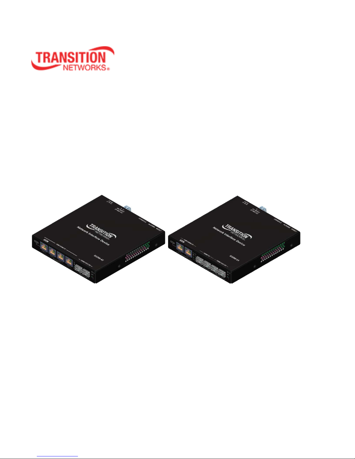
S3290
Carrier Ethernet (CE)
Network Interface Device (NID)
Install Guide
33594 Rev. D
Page 2
Transition Networks, Inc. S3290 Install Guide
Safety Warnings and Cautions
These products are not intended for use in life support products where failure of a product could reasonably be
expected to result in death or personal injury. Anyone using this product in such an application without express written
consent of an officer of Transition Networks does so at their own risk, and agrees to fully indemnify Transition Networks
for any damages that may result from such use or sale.
Attention: this product, like all electronic products, uses semiconductors that can be damaged by ESD
(electrostatic discarge). Always observe appropriate precautions when handling.
Warning: Potential for damage to equipment or personal injury.
Warning: Risk of Electrical Shock
Functional grounding point
Protective grounding point
Special considerations
S3290 Install Guide - TN PN 33594 Rev. D
Record of Revisions
Rev Date Description of Changes
B 5/1/15
C 9/25/15 Update the Rack Mount Installation information.
D
2/2/16 Updated TT-LOOP, VLAN Translation, and contact information.
Trademark notice
All trademarks and registered trademarks are the property of their respective owners. All other products or
service names used in this publication are for identification purposes only, and may be trademarks or
registered trademarks of their respective companies. All other trademarks or registered trademarks
mentioned herein are the property of their respective holders.
Copyright restrictions
© 2014-2016 Transition N e twor ks, Inc. All rights reserved. No part of this work may be reproduced or used
in any form or by any means (graphic, electronic, or mec han ic al) with out wr itte n per mission from Transition
Networks.
Address comments on this product or manual to:
Updated to v 2.1.3 which adds DDMI, HQoS, JSON, LLDP-MED, MEP BFD, MPLS-TP, PFC, Traffic Test
Loop, UDLD, and Y.1564 support.
Transition Networks Inc.
10900 Red Circle Drive, Minnetonka, MN 55343
Telephone: +1-952-941-7600 / Toll Free: 800-526-9267 / Fax: 952-941-2322
E-Mail: customerservice@transition.com / techsupport@transition.com sales@transition.com
info@transition.com
33594 Rev. D https://www.transition.com Page 2 of 30
/
Page 3

Transition Networks, Inc. S3290 Install Guide
Table of Contents
Safety Warnings and Cautions ............................................................................................................... 2
1. Introduction ...................................................................................................................................... 4
Product Description ...................................................................................................................................... 4
Models .......................................................................................................................................................... 4
Options .......................................................................................................................................................... 4
Applications .................................................................................................................................................. 4
Features ........................................................................................................................................................ 6
Specifications ................................................................................................................................................ 7
Related Manuals and Help ............................................................................................................................ 7
2. Installation ........................................................................................................................................ 8
Unpacking / Package Contents ..................................................................................................................... 8
Install Cautions and Warnings ...................................................................................................................... 8
Installation Location...................................................................................................................................... 8
Desktop Installation .................................................................................................................................. 8
Rack Mount Installation ............................................................................................................................ 9
DIN Rail Installation (WMBD) .................................................................................................................... 9
Wall Mount Installation (WMBL) .............................................................................................................. 9
Grounding and Wiring Recommendations ................................................................................................. 10
Back Panel ................................................................................................................................................... 10
Front Panel .................................................................................................................................................. 13
Connecting Power ....................................................................................................................................... 14
Power via the 12V DC (Barrel) Connector ............................................................................................... 14
Power via the DC INPUT (EuroBlock) Connector ..................................................................................... 14
Installing SFP Modules and Fiber Cables .................................................................................................... 16
Installing Copper Cables .............................................................................................................................. 17
Connecting Via the Serial CONSOLE / CLI ................................................................................................... 18
Connecting Via the MGMT Port / Web GUI ................................................................................................ 18
Factory Defaults .......................................................................................................................................... 19
Login using PuTTY Terminal Emulator Software ......................................................................................... 19
Login Using Telnet ....................................................................................................................................... 20
Login Using the Web Interface ................................................................................................................... 20
Re-Access the Web GUI via CLI Commands ................................................................................................ 20
Switching MGMT / PORT 1 Modes ............................................................................................................. 21
3. Troubleshooting .............................................................................................................................. 22
4. Service, Warranty and Tech Support ................................................................................................ 25
Contact Us ................................................................................................................................................... 25
Warranty ..................................................................................................................................................... 25
Five-Year Limited Hardware Warranty .................................................................................................. 25
Return Authorization .............................................................................................................................. 25
Service Hours .......................................................................................................................................... 25
Return Instructions ................................................................................................................................. 25
Compliance Information ............................................................................................................................. 27
Declaration of Conformity .......................................................................................................................... 27
Electrical Safety Warnings .......................................................................................................................... 29
33594 Rev. D https://www.transition.com Page 3 of 30
Page 4

Transition Networks, Inc. S3290 Install Guide
Model
Description
2xTP 4xSFP NID: T wo 10/100/1000Mbps RJ45 ports with four 100/1000Mbps SFP
ports. Includes IEEE 1588v2 with RFC 2544 Traffic Generation.
4xTP 2xSFP NID: Four 10/ 100/ 100 0Mb ps RJ45 port s w ith t wo 100/100 0M bps SFP
ports. Includes IEEE 1588v2 with RFC 2544 Traffic Generation.
Model
Description
25132
Optional Power Supply supporting an operating environment of -30°C to 70°C.
WMBL
Wall Mount Bracket (Kit) Long.
WMBD
Wall Mount Bracket DIN (DIN Rail Vertical Wall Mount Kit).
S3290-RMB
Single Rack Mount Bracket for S3290 NID.
S3290-RPS
Isolated Wide Input 20W Power Supply Assembly for S3290 Series
SFPs
See the TN SFP webpage for models and specifications.
1. Introduction
Product Description
Transition Networks’ managed S3290 NID provides advanced packet performance metering and service
creation aimed directly at customer premises and cell sites. The S3290 is optimized for business Ethernet
and mobile backhaul deployments.
The S3290 is a multi-service NID that provides SLA assurance and advanced fault management that is
MEF CE2.0 compliant. IEEE 802.1ag Service OAM, ITU Y.1731 Performance Monitoring and IEEE 802.3ah
Link OAM are standard features.
The S3290 supports advanced features such as IPv6 and IPv4, VLANs, QoS, bandwidth allocation, ring
protection, jumbo frames and numerous security features. The S3290 can be managed and provisioned
with Transition Networks Converge
SSL/SSH, RADIUS, TACACS+, Management VLAN and ACL rules.
The S3290 offers AC or DC power inputs for operation in a variety of environments. The SFP ports are
triple speed and support 100Mbps, 1000Mbps or SGMII SFPs. CWDM and Bi-Di SFPs are also supported,
allowing for flexible network architectures.
Models
The S3290 models are described below.
™
EMS or via Web, CLI and SNMP (v1, v2c & v3). T he S3290 supports
S3290-24
S3290-42
Options
The S3290 options are listed below.
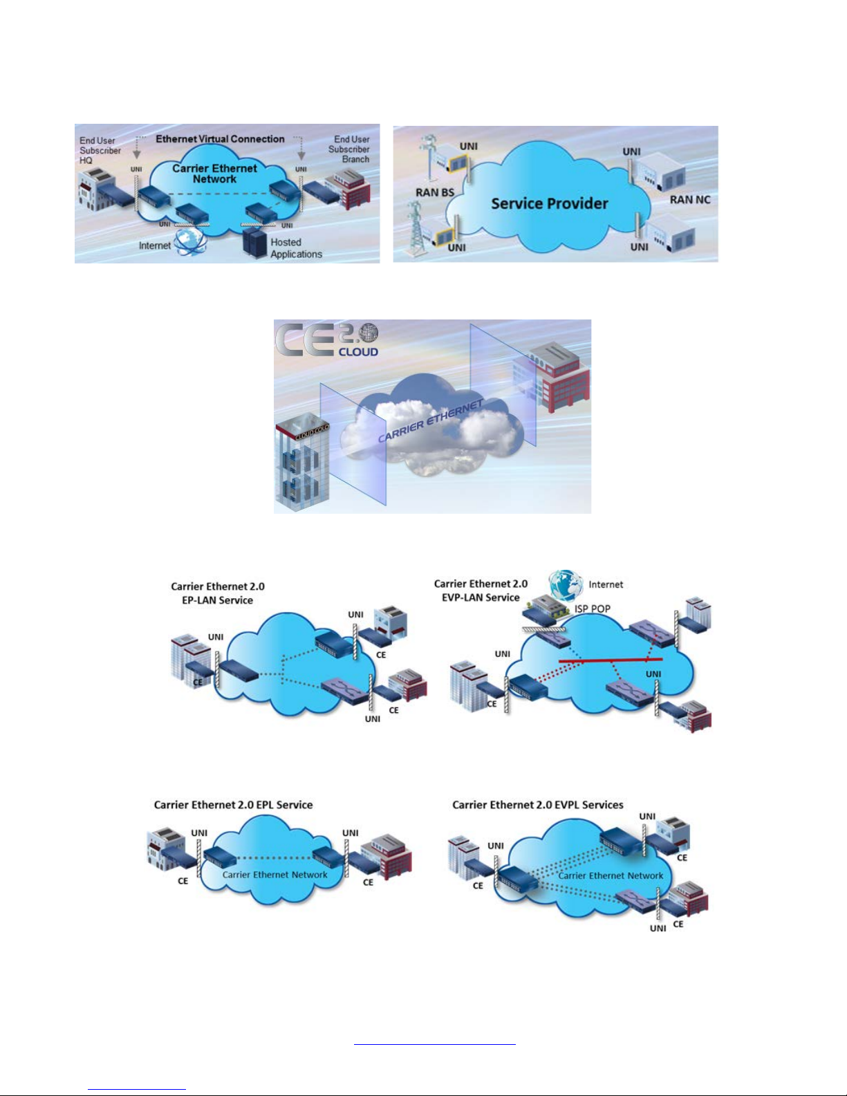
Applications
The S3290 is designed to support a wide range of MEF-based Carrier Ethernet services to include Fiber-tothe-Desk, Migration to Packet Networks, Small Cell / DAS, and Cloud Services.
33594 Rev. D https://www.transition.com Page 4 of 30
Page 5
Transition Networks, Inc. S3290 Install Guide
Several S3290 application examples are pr o vided bel o w.
CE Services Example
Cloud Services Example
E-LAN Services Example
33594 Rev. D https://www.transition.com Page 5 of 30
E-Line Services Example
Page 6

Transition Networks, Inc. S3290 Install Guide
Features
• Two/four 10/100/1000Mbps Base–T ports. Four/two 100/1000Mbps SFP ports. Any port can be
network (NNI) or client (UNI).
• Two of the SFP ports support a proprietary 2.5Gbps mode.
• TP ports support IEEE 802.3az Energy Efficient Ethernet for power saving.
• Full bandwidth 1000Mbps switching, non blocking.
• SNMP v1, v2c, and v3.
• IPv6 and IPv4 support.
• VLAN (802.1Q) Q-in-Q (C-Tag / S-Tag).
• RMON and Syslog.
• OAM Support: IEEE 802.3ah Link OAM, IEEE 802.1ag Service OAM, ITU-T Y.1731 Performance
Monitoring, and MEF E-LMI.
• Loop Protection: ITU G.8032 and IEEE RSTP, MSTP.
• G.8031 Linear Protection switching
• IEEE 1588v2 PTP (Precision Time Protocol).
• DC or AC power input (12VDC Barrel connector or 2-Pin, 21 -60VDC Terminal block).
• Jumbo Frame Support (10240 bytes maximum).
• Wire speed loopbacks.
• RFC 2544 Traffic Generation and Reports.
• Last Gasp/Dying Gasp notification via SNMP trap. Monitor Rx and Tx Dying Gasp for each port.
• SNMP traps configurable: System (Warm Start, Cold Start); Interface (Link Up. Link Down, LLDP);
AAA (Authentication Fail); Switch (STP, RMON).
• Alarm inputs/outputs: RJ-45 connector with 2-IN and 2-OUT, 10-30VDC, 40mA maximum; optically
isolated from main board. Alarm indications via Syslog and SNMP.
• E-LINE (EPL and EVPL) / E-LAN (EP-LAN and EVP-LAN) / E-ACCESS (ACCESS EPL and EVPL)
/ E-TREE (EP-TREE and EVP-TREE).
• UNI or NNI configuration.
• TOS (Type of Service) and Diffserv (Differentiated services).
• QoS (802.1p Quality of Service): 8 queues; strict priority and DWRR, shaping, policing, P-bit and
DSCP.
• Management via Industry standard CLI, Web, SSH/SSL & SNMP (v1, v2c, v3).
• Port configuration, status, statistics, and monitoring.
• RADIUS, TACACS+ and ACL.
• Remote backup / restore configuration / firmware upgrades.
• L2CP (Layer 2 Control Protocol).
• LLDP (Link Layer Discovery Protocol).
• Port Mirroring and Remote Mirroring.
• Link Aggregation Control Protocol (LACP).
• DDMI (Digital Diagnostics Monitoring Interface).
• HQoS (Hierarchical Quality of Service) with Guaranteed Bandwidth Rate.
• JSON (JavaScript Object Notation) RPC.
• LLDP-MED per TIA-1057.
• MEP BFDs (Bidirection Forwarding Detections).
• MEP Route Trace.
• PFC (802.1Qbb Priority Flow Control)
• Traffic Test Loop (Y.1564, RFC2544, and TT-Loop functions).
• UDLD (Uni Directional Link Detection) protocol support (RFC 5171).
• Y.1564 Tests and Reports.
33594 Rev. D https://www.transition.com Page 6 of 30
Page 7

Transition Networks, Inc. S3290 Install Guide
Specifications
Standards: IEEE 802.3 for 10Base-T, IEEE 802.3u for 100Base-TX IEEE 802.3z for 1000Base-X, IEEE
802.3ab for 1000Base-T, IEEE 802.3x for Flow control, IEEE 802.3ad for LACP, (Link Aggregation Control
Protocol) IEEE 802.1p for COS (Class of Service), IEEE 802.1Q for VLAN Tagging, IEEE 802.1w for RSTP
(Rapid Spanning Tree Protocol), IEEE 802.1s for MSTP (Multiple Spanning Tree Protocol), IEEE 802.1x for
Authentication, IEEE 802.1AB for LLDP (Link Layer Discovery Protocol), IEEE 802.3ah Link OAM, IEEE
802.1ag SOAM FM, IEEE 1588-2008 (v2) Precision Time Protocol (PTP), ITU Y.1731 PM.
Maximum MAC Addresses: 8K
Maximum VLANs: 4K VLANs
Maximum Frame Size: 1518-10240 bytes including FCS.
Memory: 8Mbit shared buffer memory
Data Rate Copper ports: (RJ-45): 10/100/1000 Mbps. SFP ports (empty): 100/1000 Mbps or SGMII.
Status LEDs: Power, Port Activity and Port Duplex
Dimensions Width: 5.95” [151.13 mm] Depth: 6.5” (165.1 mm) Height: 1” (25.4 mm)
Weight: S3290-42: 1.45 lb. (0.65 Kg). S3290-24: 1.40 lb (0.63 Kg.)
Input Power AC: 12 VDC (+/- 5%) via barrel connector using 100-250VAC.
DC: 21-60VDC via terminal block.
Power Consumption: These are nominal power measurements with all interfaces connected and active,
using standard 1G MM SFP modules:
• Barrel input: 520 mA at 12 VDC
• Terminal block input: 340 mA at 21 VDC
Environment: -20°C to +65°C operating temperature (Note: above 50° C industrial rated SFP modules are
required). -40°C to +85°C storage temperature. 5%– 95% operating humidity non-condensing.
Altitude: 0-10,000 feet (with de-rating)
Safety Compliance: CE, EN55022 Class A. The external wall adapter is UL listed.
Immunity Compliance: EN55024
Warranty: 5 Year Hardware
Support: TNCARE packages available for Technical Support, Hardware Support, Training, and Consulting.
Related Manuals and Help
The S3290 ships with a printed documentation postcard that po ints you to the online prod uc t
documentation. The S3290 documentation set includes:
• Product Documentation Po st car d, 33504 (printed)
• S3290 Quick Start Guide (33615)
• S3290 Install Guide (33594) (this manual)
• S3290 Web User Guide (33595)
• S3290 CLI Reference (33596)
Power Supply Included: To order the corresponding country specific power supply, add the extension to
the end of the SKU (e.g., S3290-24-NA = -NA = North America; -LA = Latin America; -EU = Europe; -UK =
United Kingdom, -SA = South Africa, -JP = Japan. -OZ = Australia; -BR = Brazil.
33594 Rev. D https://www.transition.com Page 7 of 30
Page 8
Transition Networks, Inc. S3290 Install Guide
2. Installation
Unpacking / Package Contents
Carefully unpack the contents and verify that you have received these items in the packaging:
• One S3290 NID
• One Power Supply (optional - ordered separately)
• One 6’ Console Cable, DB9 Female-to-RJ45 Male
• One Product Documentation Postcard
• One S3290 Quick Start Guide
• Four rubber feet
Save the packaging for future use.
Install Cautions and Warnings
Warning: Risk of Electrical Shock. Disconnect power before installing the S3290. Failure to observe
this warning could result in an electrical shock.
CAUTION Only qualified persons should install the S3290. Failure to observe this caution could
result in poor performance or damage to the equipment.
CAUTION Install the S3290 in an operating environment where the temperature range is from
-20°C to +65°C, with relative humidity of 5% to 90% non-condensing. Failure to observe this caution could
result in poor equipment performance.
CAUTION DO NOT install the S3290 in areas where strong electromagnetic fields (EMF) exist.
Failure to observe this caution could result in poor equipment performance and data corruption.
WARNING Disconnect power before installing and wiring the S3290 for power. Failure to observe this
warning could result in an electrical shock.
Attention: this product, like all electronic products, uses semiconductors that can be damaged by
ESD (electrostatic discarge). Always observe appropriate precautions when handling.
Installation Location
Deciding where to install the S3290 can greatly affect its performance. When sele ct ing an insta llat ion
location, consider the following:
• Install the S3290 in a fairly cool and dry place. See the “Specifications” section (page 7) and the
cautions below for the acceptable temperature and humidity ranges.
• Install the S3290 where it will not be exposed to liquid.
• Install the S3290 in a location free from strong electromagnetic field generators (such as motors).
• Do not expose or subject the S3290 to excessive vibration, dust, or direct exposure to sunlight.
• Leave at least 5 cm (1.97 in) of space around the S3290 for ventilation purposes.
Desktop Installation
Attach the Rubber Feet to the bottom of the S3290 for added stability when placing on a desktop, table top,
or other flat surface. Make sure that air flow is not blocked by any obstacles.
33594 Rev. D https://www.transition.com Page 8 of 30
Page 9
Transition Networks, Inc. S3290 Install Guide
Rack Mount Installation
The S3290-RMB can be used to mount an S3290 on a 19 inch Rack. See the S3290 Single Rack Mount
Ear Bracket Install Guide, 33659 for more information.
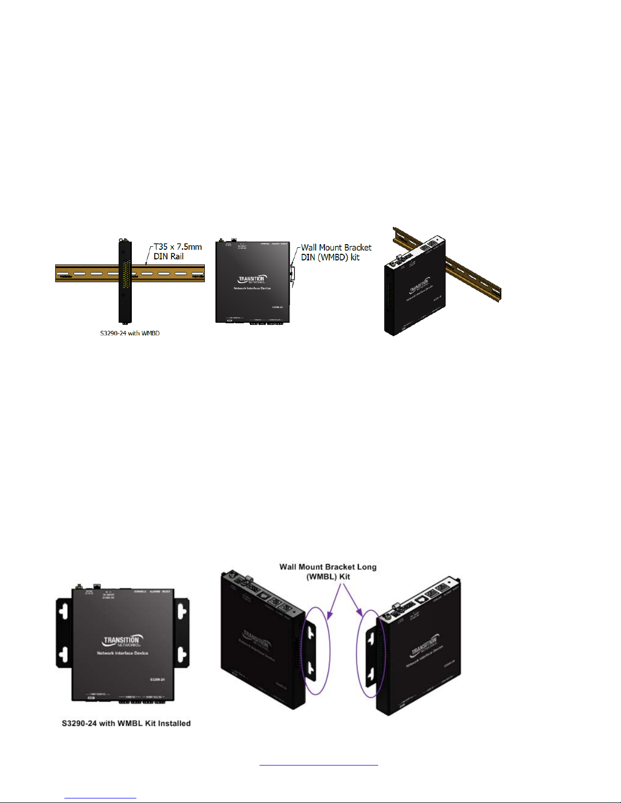
DIN Rail Installation (WMBD)
Din Rail Brackets allow stand-alone media converters to be mounted to a Din Rail, common in industrial
environments, in either a flat mount against the Din Rail or in a vertical mount in which the S3290 mounts
on its edge.
To install the S3290 in a standard DIN Rail, follow the instructions provided with the Wall Mount Bracket
DIN (WMBD) shown below:
Wall Mount Installation (WMBL)
Wall Mount Brackets are small simple “L-shaped” tabs that allow a single S3290 to be mounted anywhere
needed. The brackets are sold in pairs and are available in several sizes and types to match the different
sized media converters and space requirements.
A Wall Mount Kit is required for S3290 wallmount installations. When mounting on a wall ensure that:
• The mounting surface and fasteners used can support the S3290, mounting kit, plus cable pull.
• Cable pull does not exceed the limit.
• The S3290 install position allows proper ventilation.
To mount the S3290 on a wall:
1. Using a Phillips scr ewdriver, align the WMBL brackets with the h oles on the s ide of the S3290 and
attach with the screws provided.
2. Secure to the wall using the screws provided.
The Wall Mount Bracket Long (WMBL) is shown below:
33594 Rev. D https://www.transition.com Page 9 of 30
Page 10

Transition Networks, Inc. S3290 Install Guide
Grounding and Wiring Recommendations
CAUTION Connect the S3290 to a well-grounded surface. Failure to observe this caution could
result in electromagnetic interference (EMI) problems.
The S3290 can eliminate the effects of noise due to EMI via proper grounding. Always run the ground
connection from the ground screw to the grounded surface before connecting power.
The following wiring considerations are recommended:
• Use separate paths to route wirin g for power and device da ta cables. If power wirin g and device
data cables must cross, make sure that the wires are perpendicular at the intersection points.
• DO NOT run signal or communications wiring and power wiring in the same conduit. To avoid
interference, wire with different signal characteristics should be wired separately.
• Keep input and output wires separated.
• Label the wiring to all devices in the system for clarity.
No power ON/OFF Switch: The S3290 does not include a power ON/OFF switch; therefore, when power is
applied to the switch, it immediately powers Up.
Back Panel
The S3290 back panel is shown and described below.
RESET: The RESET button functions include:
1) Press and immediately release the RESET button to :
a. Restart the device.
2) Press and hold the RESET button for more than 5 seconds to:
a. Load the factory default configuration,
b. copy the running-configuration to the startup-configuration,
c. restart the device in factory default configuration (note that this resets the unit IP address).
The RESET button can be disabled (ignored) via the CLI. Refer to the S3290 CLI Refer enc e manual.
Note: Restoring factory default can also be performed by making a physical loopback between port 1 and
port 2 within the first minute after switch reboot. In the first minute after boot, 'loopback' packets will be
transmitted at port 1. If a 'loopback' packet is received at port 2, then the switch will do a restore to defaults.
Press the Enter key to display the logon sequence, and then enter your User Name and Password.
33594 Rev. D https://www.transition.com Page 10 of 30
Page 11

Transition Networks, Inc. S3290 Install Guide
Alarm Outputs
Alarm State & LED
behavior
Trigger
setting
Alarm relay out state
Asserted & Active
Close
relay closed
De-asserted & Not active
Close
relay open
Asserted & Active
Open
Relay open
De-asserted & Not active
Open
Relay closed
Wire state
Trigger
setting
Alarm state & LED
behavior
Energized
Close
Asserted & Active
De-energized
Close
De-asserted & Not active
Energized
Open
De-asserted & Not active
De-energized
Open
Asserted & Active
ALARMS: Alarm inputs and outputs are RJ-45 connector with 2-IN and 2-OUT; 10-30VDC, 40mA
maximum; optically isolated from main board. You can connect up to two alarm inputs from external devices
in your environment (e.g., a fire alarm, a door, a temperature gauge) to the alarm input port on the switch
front panel. The figure below shows the location of the alarm pinouts. For each alarm input, you can
configure an open or closed circuit to trigger an alarm and configure the severity of the alarm. A triggered
alarm generates a system message. If you enter a descriptive name for the alarm, that name is included in
the system message. A triggered alarm also turns on the LED display. The LED is normally off, meaning no
alarm condition exists.
You can set the alarm severity to Info, Warning, or Error. The severity is included in the alarm message and
also sets the S2 LED color when the alarm is triggered. The S2 LED is amber for an Info alarm, red for a
Warning alarm, and blinking red for an Error alarm. If not set, the default alarm severity is Info.
You can use the S3290 web GUI or CLI to configure alarm contacts; see the related manual for details.
The ALARMS port pinning and basic block diagram are shown below.
The Alarm Input and Output truth tables are provided below.
Alarm Inputs
33594 Rev. D https://www.transition.com Page 11 of 30
Page 12

Transition Networks, Inc. S3290 Install Guide
CONSOLE: RJ-45 serial port 115200 baud CLI port. The S3290 RJ-45 console port allows root access to
its CLI (Command Line Interface) via a computer, regardless of the state of the switch (unless it is
completely dead). By connecting to the console port, out-of-band remote access to the CLI of the switch is
possible. This creates a secondary path to the switch outside the bandwidth of the network, which needs to
be secured without relying on the primary network.
DC INPUT: 21-60 VDC EuroBlock. One of two power input options (not redundant power inputs).
CAUTION : only one power input should be connected at any time.
Strain Relief:
Provides an optional means to offload cable strain.
12V DC: The barrel input requires 12VDC +/-5%. One of two power input options (not
redundant power inputs).
CAUTION : only one power input should be connected at any time.
Grounding Lug: Provides an option for grounding the S3290. See “Grounding and
Wiring Recommendations” on page 10.
33594 Rev. D https://www.transition.com Page 12 of 30
Page 13

Transition Networks, Inc. S3290 Install Guide
Front Panel
The S3290 front panels are shown and described belo w.
S3290-24 (above) / S3290-42 (below).
MGMT / PORT 1: Port1 (MGMT) is a normal data port, but by default it will be in a
separate private VLAN (PVLAN 1) that you can remove. You can enable or disable outof-band management on PORT 1. PORT 1 can be optionally configured to support
either out-of-band management or it can be used as a normal data UNI/NNI port.
See Connecting Via the MGMT Port / Web GUI on page 18. By default, PORT 1 is enabled as a
Management port with a default IP and subnet mask. See Factory Defaults on page 19. Full instructions for
disabling the management function and how to use the port as a normal data port are provided in the CLI
Reference and Web User Guide manuals.See also Switching MGMT / PORT 1 Modes on page 21.
GigabitEthernet 1/1 (Port 1) is configured by default to act as a management port. This is achieved by
placing Port 1 in Private VLAN 6 which isolated traffic at layer 2 on this port from other front ports which are
by default placed into Private VLAN 1.
PORT 2 - PORT 4 (or PORT 1 & 2): Ethernet RJ-45 (10M/100M/1 Gbps) twisted pair ports (IEEE
10/100/1000Base-T interfaces). The Port 1 and Port 2 (or PORT 1-4) LEDs are shown and
described below:
LED1: Link/Activity/Duplex: ON = Link, OFF= No link
BLINK = Activity
Green = Full duplex, Yellow = Half duplex
LED2: Speed: Green = 1000Mbs, Yellow = 100Mbs, OFF = 10Mbs
PORT 5 & 6 (or PORT 3 - PORT 6 on the S3290-42): Two (or four) SGMII interfaces. The Serial Gigabit
Media-independent Interface (SGMII) interfaces can operate at multiple speeds of 100M/1G/2.5G bps.
P3 - P6 LED (P5 - P6 on the S3290-42): fiber link status. When lit in green, indicates a 1G fiber
link / activity. When lit in amber, indicates a 100M fiber link / activity. When off indicates no fiber
link established.
PWR LED: Green Power LED: On = power applied to the PC board. Flashes Green during S3290 b oot up.
S1 LED: System Status LED (Bi-color Green and Amber):
During boot up – Amber
Normal operation – Green
Firmware upgrade – Flashes Green
Fatal condition logged – Flashes Amber
33594 Rev. D https://www.transition.com Page 13 of 30
Page 14

Transition Networks, Inc. S3290 Install Guide
S2 LED: S2 is used for alarms. You can set the alarm severity to Info, Warning, or Error.
The severity is included in the alarm message and also sets the S2 LED color when the alarm is
triggered. The S2 LED is amber for an Info alarm, red for a Warning alarm, and blinking red for
an Error alarm. If not set, the default alarm severity is Info. See the back panel ALARMS port
description on page 13.
S2 LED is green when at least one alarm source is being monitored (enabled) if the severity level is Info.
S2 LED is amber when at least one event source has triggered if the severity level is Warning.
S2 LED is flashing amber when at least one event source has triggered if the severity level is Error.
S2 LED is off when all event sources are disabled if the severity level is Error.
Connecting Power
You can connect S3290 power either via the 12V DC Connector or via the
DC INPUT Connector (not redundant power inputs).
CAUTION : only one power input should be connected at any time.
Note that when power is initially applied (or when power is recycled) the S3290
front panel LEDs all light for approximately 10 seconds. Some LEDs will remain lit,
depending on the S3290 operating sta tus and port connections.
Power via the 12V DC (Barrel) Connector
Connct the Barrel connector to the DC INPUT Connector.
Power via the DC INPUT (EuroBlock) Connector
DC INPUT: 21-60 VDC EuroBlock (Terminal Block). The procedures below describe how to
remove the terminal block, connect the Power wires to the Terminal Block, and then reinstall the
terminal block and verify the Power wire connections.
Removing the Terminal Block (TB)
1. Loosen the “2” mounting screws that attach the “primary” Terminal Block (TB) to the S3290 chassis.
2. Pull the TB from the S3290 chassis connector as shown below.
.
Notes: It is a good practice to turn OFF input and load power, and unplug the power Terminal Block before
making wire connections. Otherwise, a metal screwdriver blade can inadvertently short the terminal
connections to the grounded enclosure. However, in some instances this is not possible as this may be a
bussed power rail providing power to numerous other devices.
33594 Rev. D https://www.transition.com Page 14 of 30
Page 15

Transition Networks, Inc. S3290 Install Guide
Terminal Block
Power Wires
Wire Securing
Screws
Chassis Mounting
Screws Qty (2)
Wire Slots
Connect to AC/DC
power source
Also note:
• The range of suitable wire for the terminal block is 12 to 26 AWG.
• The power source must be safety certified.
Connecting Power Wires to the Terminal Block
1. Strip the wires to the proper length.
2. Insert the positive and neg ative power wires into V+ and V- contacts r espectively of the Terminal Block
(note polarity on the chassis of the switch). Make sure the wires are secure. See figure below.
3. Insert the positive and negative power wires into V+ and V- contacts respectively into the power
source—make sur e the wires are secure. S ee the f igu r es abo ve. Insert the positive and negati ve p o wer
wires into V+ and V- contacts respectively into the power source—make sure the wires are secure.
See the figure below.
Reinstalling the Terminal Block and verifying power wire connection s
4. Reinstall the Terminal Block into the primary location on the S3290.
5. Tighten the two screws to secure the Terminal Block to the S3290 chassis.
6. Turn the power source ON and obs erve that the green front panel PWR (power) LED is lit, indicating
that power is applied to the S3290.
33594 Rev. D https://www.transition.com Page 15 of 30
Page 16

Transition Networks, Inc. S3290 Install Guide
LC Fiber
Cable
SFP
Switch
Fully Inserted SFP
Switch
Installing SFP Modules and Fiber Cables
Warning
Visible and invisible laser radiation when open: DO NOT stare into the beam or view the beam directly with
optical instruments. Failure to observe this warning could result in an eye injury or blindness.
Use of controls, adjustments or the performance of procedures other than those specified herein may result
in hazardous radiation exposure.
Avoid bending fiber-optic cable beyond its minimum bend radius—any arc smaller than a few inches in
diameter can damage the cable and cause problems that are difficult to diagnose.
Installing SFPs
1. Attach an ESD-preventive wrist stra p to your wrist and to a bare-metal grounded surface.
2. Have a replacement SFP or a trans ceiver-cage plug ready, as well as an antistatic mat and a rubber
safety cap for the SFP.
3. Locate the proper fiber cable.
4. Position the cable at the SFP as shown below.
Caution: Disconnect all cables before removing or installing an SFP module to prevent damage to the fiber
cable.
5. Insert the fiber cable ends completely into the SFP as shown below.
6. Insert the SFP fully into the cage as shown below.
Removing SFPs
7. Attach an ESD-preventive wrist stra p to your wrist and to a bare-metal grounded surface.
8. Have a replacement SFP or a trans ceiver-cage plug ready, as well as an antistatic mat and a rubber
safety cap for the SFP.
9. Disconnect the LC cable for the SFP.
10. Pull the bale clasp handle out from the SFP to unlock the SFP.
11. Grasp the SFP bale clasp and pull the SFP approximately 0.5 inches (1.3 cm) out of the cage.
12. Using your fingers, grasp the body of the SFP and pull it completely from the cage.
13. Insert the rubber protector into the SFP module to protect it.
14. Place the SFP module in an antistatic bag or other protective environment.
33594 Rev. D https://www.transition.com Page 16 of 30
Page 17

Transition Networks, Inc. S3290 Install Guide
Pin
Out Jack Pin Assignments
1
Outgoing Data 1 (+)
2
Outgoing Data 2 (-)
3
Incoming Data 1 (+)
4
Not Connected
5
Not Connected
6
Incoming Data 2 (-)
7
Not Connected
8
Not Connected
1
2
3
6
Straight-Through Cable Crossover Cable
1
2
3
6
1
2
3
6
1
2
3
6
Twisted Pair #1
Twisted Pair #2
Twisted Pair #1
Twisted Pair #2
Installing Copper Cables
Copper Cable Configuration
Depending on the equipment type, data terminal equipment (DTE) or data communication equipment
(DCE), use a crossover or straight-through cable. See figure below.
Connecting Ethernet Cables
1. Locate or build an IEEE 802.3 compliant cable with male RJ-45 connectors installed at both ends as
shown below.
2. Connect the RJ-45 connector at one end of the cable to the S3290 RJ-45 port.
3. Connect the RJ-45 connector at the other end of the cable to the RJ-45 Ethernet network port.
33594 Rev. D https://www.transition.com Page 17 of 30
Page 18

Transition Networks, Inc. S3290 Install Guide
Connecting Via the Serial CONSOLE / CLI
The S3290 CLI interface is an Industry standard CLI and consists of different configuration commands
structure with ability to configure and view the configuration using the Serial Console, Telnet, or SSH.
Connecting Via the MGMT Port / Web GUI
The S3290 supports the current version of most popular Web browsers.
See the S3290 Web User Guide or the S3290 CLI Reference manual for details on configurati on and
management methods.
To login using the ser i al inter f ac e (e.g., HyperTerminal) use the setup 115200, 8, none, 1, none.
See the S3290 CLI Reference manual for details.
Type help, ?, or press the Enter key to display the commands as shown below.
33594 Rev. D https://www.transition.com Page 18 of 30
Page 19

Transition Networks, Inc. S3290 Install Guide
DHCP
Ipv4 Address
Ipv6 Address
Enabled
192.168.0.1
::192.0.2.1
Factory Defaults
The S3290 comes with the following defaults:
Note: after power up, the S3290 has DHCP enabled. If a DHCP server is available, the S3290 will obtain an
IP address from the DHCP server. If no DHCP server is available, after 70 seconds, the S3290 will fall back
to the default IP address of 192.168.0.1/24.
Static IP configuration
You can change the defaults via the CLI. Note: you may want to save the existing config to startup config
first by using the copy running-config command. See the CLI Reference manual for details. To manually
configure the IP address:
1. At the command prompt type # configure terminal and press the Enter key to enter config mode.
2. Enter the command (config)# interface vlan 1 and press the Enter k ey to enter the interf ace config
mode.
3. Set the IP to 192.168.1.110 and subnet to 255.255.255.0 (substitut e what you would like the static IP
and subnet to be). You can change the current IP address using the following command:
(config-if-vlan)# ip address 192.168.1.110 255.255.255.0
See the S3290 CLI Referenc e manual for CLI command information for CLI details.
4. To verify the chang e, you can log in to th e S3290 Web GUI using IP address 192.168.1.110. See the
S3290 Web User Guide for more information.
Login using PuTTY Terminal Emulator Software
1. Start a PuTTY session. In the PuTTY dialog box in the “Host Name {or IP Address}” field, enter the IP
address of the switch (e.g., 192.168.1.110). In the Port field, enter 22.
2. Name the session in the “Saved Sessions” field (e.g., as S3290 SW).
3. Click the Save button and the dialog box displays.
4. Click the Open button to launch the login screen.
Note: If a Security Alert displays, click YES, if you trust the host and the key will be added to the
PuTTY cache. Click NO if you do not want to register the key for this session.
5. At the login prompt, type “admin” (default/lowercase).
6. Press the Enter key twice to bring up the Root (top) level commands as shown below.
See the S3290 CLI Referenc e manual for CLI command information for CLI details.
33594 Rev. D https://www.transition.com Page 19 of 30
Page 20

Transition Networks, Inc. S3290 Install Guide
Login Using Telnet
1. Use the Windows Start > Command Prompt menu path to display the command.
2. At the command prompt type Telnet and then 192.168.1.110 and press the Enter key
3. At the Username prompt, enter admin (lower case) and press the Enter key.
4. At the Password prompt press the Enter key to display the # prompt.
5. At the # prompt enter CLI commands as desired.
See the S3290 CLI Referenc e manual for CLI command information for CLI details.
Login Using the Web Interface
1. Launch a web browser (Internet Explorer/FireFox).
2. Enter the S3290 IP address (e.g., 192.168.0.1) in the b rowser URL field.
3. Press the Enter key to launch the login dialog box.
4. In the user name field type “admin” (lowercase) and leave the password field empty (no password).
5. Press the Enter key to launch the S3290 web GUI.
6. See the S3290 Web User Guide manual for web GUI configuration, monitoring, diagnostics, and
maintainance.
Re-Access the Web GUI via CLI Commands
You can use the following CLI commands to regain web GUI access (e.g., after a Software Upload).
# show ip int brief
Vlan Address Method Status
---- -------------------- -------- ------
# conf term
(config)# int vlan 1
(config-if-vlan)# ip addr 192.168.1.110 255.255.255.0
(config-if-vlan)# end
# show ip int brief
Vlan Address Method Status
---- -------------------- -------- ------
1 192.168.1.110/24 Manual UP
#
You can then access the web GUI via the IP address and netmask entered (e.g., 192.168.1.110 and
255.255.255.0 in the example abo ve). Se e the S3290 CLI Reference manual for details.
33594 Rev. D https://www.transition.com Page 20 of 30
Page 21

Transition Networks, Inc. S3290 Install Guide
Switching MGMT / PORT 1 Modes
The S3290 MGMT / PORT 1 is a normal data port, but by default it will be in a separate private VLAN that
you can remove. You can enable or disable out-of-band management on Port 1. Port 1 can be optionally
configured to support either out-of-band management or it can be used as a normal data UNI/NNI port.
By default, Port 1 is enabled as a management port with a default IP (192.168.0.1/24) and subnet mask.
By default, all ports are VLAN unaware and members of VLAN 1 and Private VLAN 1.
To configure Port 1 as a normal front panel data port, use the settings below.
Normal front port:
interface GigabitEthernet 1/1
!
Management Port:
interface GigabitEthernet 1/1
no pvlan 1
pvlan 6
no ip dhcp forwarding
no spanning-tree
!
Configure the Default Management Port as a Data Port
The GigabitEthernet 1/1 (MGMT / PORT 1) is configured as a Management Port by default:
Alternatively, any port can be designated as a Management port. To change GigabitEthernet 1/1 to act as a
data port:
1. Disable spanning-tree on the port designated for Management. Remove pvlan 1 from the new interface
and disable dhcp forwarding, and add pvlan6:
(config)# int Gi 1/2
(config-if)# no spanning-tree
(config-if)# no pvlan 1
(config-if)# no ip dhcp forwarding
(config-if)# pvlan 6
2. Physically connect to the newly designated Management port.
3. Enable pvlan 1 for the new port designated as a data port.
4. If necessary enable spanning-tree on the new data port.
Additional instructions for disabling management are provided in CLI and Web manuals.
33594 Rev. D https://www.transition.com Page 21 of 30
Page 22

Transition Networks, Inc. S3290 Install Guide
3. Troubleshooting
This section provides basic S3290 troubleshooting procedures.
1. Verify the Product Description, Models, Applications, Features, an d Specifications in the “Introduction”
section starting on page 4 of this manual.
2. Verify the procedures in section 2. Installation starting on page 8 of this manual.
3. Make sure your particular model supports the function attempted.
4. Verify the Installation. Check the Operating System, Web Browser, Telnet Client, and/or Terminal
Emulation package support.
5. Respond to an y S3290 error m essages (see the Er ror Messages sec tion of the S32 90 CLI Reference
or the S3290 Web User Guide.
6. Run the S3290 Diagnostics tes ts and verification functi ons (e.g., P ing, VeriPHY). See the “Diagnos tics”
section of the S3290 Web User Guide manual.
7. Check the S3290 operating parameters (e.g., Information, CPU Load, Log, Detailed Log). See the
“Operation” section of the S3290 Web User Guide manual.
8. If you can access the S32 90 v ia PuT T Y or HyperTerminal but not via the web inter fac e, in config mode,
enter the default keep_ip CLI command and try accessing the S3290 web interface again.
9. If you have problem s displaying t he S3290 web interfac e in IE, tr y displa ying in C om patibilit y View from
the IE Tools > Compatibility View menu path.
10. Record the error condition. See “Recordi ng Mod el and S ystem Information” below.
11. Contact TN Tech Support. See section“4. Service, Warranty and Tech Support” on page 25.
33594 Rev. D https://www.transition.com Page 22 of 30
Page 23

Transition Networks, Inc. S3290 Install Guide
Recording Model and System Information
After performing the troubleshooting procedures, and before calling or emailing Technical Support, please
record as much information as possible in order to help the Transition Networks Tech Support Specialist.
1. Select the S3290 Configuration > System > Information menu path. (From the CLI, use the show
commands needed to gather the information below or as requested by the TN Suppor t Spec ial ist).
2. Record S3290 Model Information: Product ID: _____________________________
Serial #: ___________________________ Board Rev: ____________________________
MAC Address: ______________________ Chip ID: _______________________________
System Uptime: _____________________ Software Version: ________________________
3. Record the Monitor menu information:
Monitor > System > Information: _____________________________________________________
Monitor > System > IP Status: ________________________________________________________
LED Status: ______________________________________________________________________
4. Provide additional Model and System information to your Technical Support Specialist. See the
“Troubleshooting” section above.
Your Transition Networks service contract number: _____________________________________
A description of the failure: _________________________________________________________
________________________________________________________________________________
________________________________________________________________________________
A description of any action(s) already taken to resolve the problem (e.g., changing mode, rebooting,
etc.): ____________________________________________________________________________
_________________________________________________________________________________
________________________________________________________________________________
The serial and revision numbers of all involved Transition Networks products in the network:
_________________________________________________________________________________
_________________________________________________________________________________
A description of your network environment (layout, cable type, etc.): _________________________
_________________________________________________________________________________
________________________________________________________________________________
Network load and frame size at the time of trouble (if known): ______________________________
33594 Rev. D https://www.transition.com Page 23 of 30
Page 24

Transition Networks, Inc. S3290 Install Guide
The device history (i.e., have you returned the device before, is this a recurring problem, etc.):
_________________________________________________________________________________
________________________________________________________________________________
Any previous Return Material Authorization (RMA) numbers: _______________________________
Serial Label on S3290-24 Bottom
33594 Rev. D https://www.transition.com Page 24 of 30
Page 25

Transition Networks, Inc. S3290 Install Guide
4. Service, Warranty and Tech Support
Contact Us
Technical Support: Technical support is available 24-hours a day
US and Canada: 1-800-260-1312
International: 00-1-952-941-7600
Main Office
tel: +1.952.941.7600 | toll free: 1.800.526.9267 | fax: 952.941.2322
sales@transition.com | techsupport@transition.com | customerservice@transition.com
Address
Transition Networks
10900 Red Circle Drive
Minnetonka, MN 55343, U.S.A.
Web: https://www.transition.com
Warranty
Five-Year Limited Hardware Warranty
Transition Networks warrants to the original consumer or purchaser that each of its S3290 products and all
components thereof, will be free from defects in material and/or workmanship for a period of five years from
the original factory shipment date. Any warranty hereunder is extended to the original consumer or
purchaser and is not assignable. Transition Networks makes no express or implied warranties including, but
not limited to, any implied warranty of merchantability or fitness for a particular purpose, except as
expressly set forth in this warranty. In no event shall Transition Networks be liable for incidental or
consequential damages, costs, or expenses arising out of or in connection with the performance of the
product delivered hereunder. Transition Networks will in no case cover damages arising out of the product
being used in a negligent fashion or manner.
Return Authorization
To return a defective product for warranty coverage, contact Transition Networks's technical support
department for a return authorization number. Transition's technical support department can be reached
through any of the following means:
Service Hours
USA: 8:00 PM Sunday through 8:00 PM Friday CST
After Hours: Calls will be answered by an on call engineer.
Return Instructions
Send the defective product postage and insurance prepaid to the following address:
Transition Networks, Inc.
10900 Red Circle Drive
Minnetonka, MN 55343 USA
Attn: RETURNS DEPT: CRA/RMA # ___________
33594 Rev. D https://www.transition.com Page 25 of 30
Page 26

Transition Networks, Inc. S3290 Install Guide
Failure to properly protect the product during shipping may void this warranty. The return authorization
number must be written on the outside of the carton to ensure its acceptance. We cannot accept delivery of
any equipment that is sent to us without a CRA or RMA number.
CRA’s are valid for 60 days from the date of issuance. An invoice will be generated for payment on any
unit(s) not returned within 60 days.
Upon completion of a demo/ evaluation test period, units must be returned or purchased within 30 days. An
invoice will be generated for payment on any unit(s) not returned within 30 days after the demo/ evaluation
period has expired.
The customer must pay for the non-compliant product(s) return transportation costs to Transition Networks
for evaluation of said product(s) for repair or replacement. Transition Networks will pay for the shipping of
the repaired or replaced in-warranty product(s) back to the customer (any and all customs charges, tariffs,
or/and taxes are the customer's responsibility).
Before making any non-warranty repair, Transition Networks requires a $200.00 charge plus actual shipping
costs to and from the customer. If the repair is greater than $200.00, an estimate is issued to the customer
for authorization of repair. If no authorization is obtained, or the product is deemed ?not repairable,?
Transition Networks will retain the $200.00 service charge and return the product to the customer not
repaired. Non-warranted products that are repaired by Transition Networks for a fee will carry a 180-day
limited warranty. All warranty claims are subject to the restrictions and conventions set forth by this
document.
Transition Networks reserves the right to charge for all testing and shipping incurred, if after testing, a return
is classified as "No Problem Found."
THIS WARRANTY IS YOUR ONLY REMEDY. NO OTHER WARRANTIES, SUCH AS FITNESS FOR A
PARTICULAR PURPOSE, ARE EXPRESSED OR IMPLIED. TRANSITION NETWORKS IS NOT LIABLE
FOR ANY SPECIAL, INDIRECT, INCIDENTAL OR CONSEQUENTIAL DAMAGES OR LOSSES,
INCLUDING LOSS OF DATA, ARISING FROM ANY CAUSE OR THEORY. AUTHORIZED RESELLERS
ARE NOT AUTHORIZED TO EXTEND ANY DIFFERENT WARRANTY ON TRANSITION NETWORKS'S
BEHALF.
33594 Rev. D https://www.transition.com Page 26 of 30
Page 27

Transition Networks, Inc. S3290 Install Guide
Compliance Information
Standards
CISPR22/EN55022 Class A, CE Mark, and IEC 61850-3
FCC Regulations
NOTE: This equipment has been tested and found to comply with the limits for a Class A digital device,
pursuant to Part 15 of the FCC Rules. These limits are designed to provide reasonable protection against
harmful interference when the equipment is operated in a commercial environment. This equipment
generates, uses, and can radiate radio frequency energy and, if not installed and used in accordance with
the instruction manual, may cause harmful interference to radio communications. Operation of this
equipment in a residential area is likely to cause harmful interference in which case the user will be required
to correct the interference at his own expense.
Canadian ICES-003
This Class A digital apparatus complies with Canadian ICES-003.
Cet appareil numériqué de la classe A est conformé à la norme NMB-003 du Canada.
CE Marking
This is a Class A product. In a domestic environment, this product could cause radio interference; as a
result, the customer may be required to take adequate preventative measures.
UL Listed Power Supply
The Power Supply is tested and recognized by the Underwriters Laboratories, Inc.
Declaration of Conformity
33594 Rev. D https://www.transition.com Page 27 of 30
Page 28

Transition Networks, Inc. S3290 Install Guide
European Regulations
WARNING: This is a Class A product. In a domestic environment, this product could cause radio
interference in which case the user may be required to take adequate measures.
Achtung ! Dieses ist ein Gerät der Funkstörgrenzwertklasse A. In Wohnbereichen können bei Betrieb
dieses Gerätes Rundfunkstörungen auftreten. In diesem Fäll ist der Benutzer für Gegenmaßnahmen
verantwortlich.
Attention ! Ceci est un produit de Classe A. Dans un environment domestique, ce produit risque de créer
des interférences radioélectriques, il appartiendra alors à l’utilsateur de prende les measures spécifiques
appropriées.
In accordance with European Union Directive 2002/96/EC of the European Parliament and of the
Council of 27 January 2003, Transition Networks will accept post usage returns of this product
for proper disposal. The contact information for this activity can be found in the ‘Contact Us’
portion of this document.
CAUTION: RJ connectors are NOT INTENDED FOR CONNECTION TO THE PUBLIC
TELEPHONE NETWORK. Failure to observe this caution could result in damage to the public
telephone network.
Der Anschluss dieses Gerätes an ein öffentlickes Telekommunikationsnetz in den EG-Mitgliedstaaten
verstösst gegen die jeweligen einzelstaatlichen Gesetze zur Anwendung der Richtlinie 91/263/EWG zur
Angleichung der Rechtsvorschriften der Mitgliedstaaten über Telekommunikationsendeinrichtungen
einschliesslich der gegense iti gen An erkennung ihrer Konformität.
33594 Rev. D https://www.transition.com Page 28 of 30
Page 29

Transition Networks, Inc. S3290 Install Guide
Electrical Safety Warnings
Electrical Safety
IMPORTANT: This equipment must be installed in accordance with safety precautions.
Elektrische Sicherheit
WICHTIG: Für die Installation dieses Gerätes ist die Einhaltung von Sicherheitsvorkehrungen
erforderlich.
Elektrisk sikkerhed
VIGTIGT: Dette udstyr skal 29nstallers I overensstemmelse med sikkerhedsadvarslerne.
Elektrische veiligheid
BELANGRIJK: Dit apparaat moet in overeenstemming met de veiligheidsvoorschriften worden
geïnstalleerd.
Sécurité électrique
IMPORTANT : Cet équipement doit être utilisé conformément aux instructions de sécurité.
Sähköturvallisuus
TÄRKEÄÄ : Tämä laite on asennettava turvaohjeiden mukaisesti.
Sicurezza elettrica
IMPORTANTE: questa apparecchiatura deve essere installata rispettando le norme di sicurezza.
Elektrisk sikkerhet
VIKTIG: Dette utstyret skal 29nstallers I samsvar med sikkerhetsregler.
Segurança eléctrica
IMPORTANTE: Este equipamento tem que ser instalado segundo as medidas de precaução de segurança.
Seguridad eléctrica
IMPORTANTE: La instalación de este equipo deberá llevarse a cabo cumpliendo con las precauciones de
seguridad.
Elsäkerhet
OBS! Alla nödvändiga försiktighetsåtgärder måste vidtas när denna utrustning används.
33594 Rev. D https://www.transition.com Page 29 of 30
Page 30

Transition Networks, Inc. S3290 Install Guide
Transition Networks
10900 Red Circle Drive
Minnetonka, MN 55343 USA
Tel: 952- 941-7600 or 1-800-526-9267
Fax: 952-941-2322
Copyright© 2014-2016 Transition Networks. All rights reserved. Printed in the U.S.A.
S3290 Install Guide 33594 Rev D
33594 Rev. D https://www.transition.com Page 30 of 30
 Loading...