

LACTPWR
10/100/10001000Base-X
USB
DPX
100Base-FX
10/100Base-TX
USB
CBFFG
LACTPWR
LACT FD LACT FD
PWR
LACT
100Base-X 1000Base-X
PWR
LNK
DPX
1000Base-X 1000Base-X
PWR
1 2
LNK
10/100/10001000Base-X
LNK
LNK
PWR USB
USB
USB
USB
USB
USB
DPX
100Base-FX
10/100Base-TX
USB
CFBRM
LACTPWR
CFBRM
FBRM1xxx-1xx & BFFG1xxx-1xx
Chassis & Stand-Alone Remotely Managed
Devices
Manual
33345, Revision D


Transition Networks
Table of contents
Section I: ..................................................................................................................................................................1
Product Description ................................................................................................................................................1
General description.......................................................................................................................................2
Product features.............................................................................................................................................3
Management methods...................................................................................................................................4
Hardware description....................................................................................................................................5
FBRM/BFFG13xx-1xx fiber-to-fiber gigabit models .................................................................................13
Redundant SFBRM1040-140 models ........................................................................................................15
Section II: ...............................................................................................................................................................17
Hardware Installation ...........................................................................................................................................17
Installing CFBRM/CBFFG cards into point system chassis ......................................................................18
Installing SFBRM/SBFFG standalone models ............................................................................................19
Installing fiber and copper cables ..............................................................................................................20
Connecting power (standalone models)...................................................................................................22
Section III: ..............................................................................................................................................................24
USB Driver Installation & COM Port Setup........................................................................................................24
Installing USB driver....................................................................................................................................25
Configuring COM port................................................................................................................................29
Section live: ...........................................................................................................................................................32
Initial Device Setup...............................................................................................................................................32
USB CLI access ............................................................................................................................................33
Initial Device setup via USB CLI ................................................................................................................35
Initial Device setup via telnet (directly to Device) ..................................................................................38
Initial Device setup via chassis agent MMU, web-based ........................................................................41
Initial Device setup IP web-based (directly to Device) ...........................................................................44
Sections V: .............................................................................................................................................................49
Device Management.............................................................................................................................................49
SNMP IP-based management.....................................................................................................................50
Device management via chassis agent (MMU) web-based.....................................................................53
Device management via IP web-base (directly to Device).....................................................................56
Section VI:..............................................................................................................................................................59
Software Features..................................................................................................................................................59
Software feature descriptions .....................................................................................................................60
Software security feature descriptions .......................................................................................................69
Section VIl:.............................................................................................................................................................71
Operations .............................................................................................................................................................71
Status LEDs...................................................................................................................................................72
OAM Device management configuration options ...................................................................................75
Firmware upgrades......................................................................................................................................76
Continued on next page
24-Hour Technical Support: 1-800-260-1312 Intern ational: 00-1-952-941-7600 i

Transition Networks
Table of contents, continued
Section Vlll: ...........................................................................................................................................................82
Troubleshooting ....................................................................................................................................................82
Troubleshooting problem and corrective action table.............................................................................83
Section lX:..............................................................................................................................................................88
Copper Cable & Fiber Optic Specifications .......................................................................................................88
Copper cables ..............................................................................................................................................89
Fiber optic cable and connector specifications........................................................................................90
Section X:.............................................................................................................................................................101
Contact Us, Warranty, & Conformity Information...........................................................................................101
Contact us...................................................................................................................................................102
Conformity declaration .............................................................................................................................103
Warranty.....................................................................................................................................................105
Compliance information...........................................................................................................................107
Appendix A:.........................................................................................................................................................109
FBRM/BFFG Part Numbers.................................................................................................................................109
FBRM copper-to-fiber part numbers........................................................................................................109
FBRM fiber-to-fiber part numbers ............................................................................................................112
BFFG copper-to-fiber part numbers.........................................................................................................115
BFFG fiber-to-fiber part numbers .............................................................................................................116
Appendix B:.........................................................................................................................................................120
FBRM/BFFG Technical Specification ................................................................................................................120
Specifications, notices, and warnings......................................................................................................120
Appendix C:.........................................................................................................................................................122
Device Commands & Descriptions...................................................................................................................122
Appendix D: ........................................................................................................................................................129
IP-Based and Chassis Management Parameters...............................................................................................129
Appendix E: .........................................................................................................................................................141
Request for Comment (RFC) Compliance.........................................................................................................141
Index.....................................................................................................................................................................143
ii

Transition Networks
Trademark, copyright information, and about this manual
Trademark
Copyright
restrictions
About this
manual
All trademarks and registered trademarks are the property of their respective owners.
© 2008 Transition Networks: All rights reserved. No part of this work may be
reproduced or used in any form or by any means—graphic, electronic, or
mechanical—without written permission from Transition Networks.
Printed in the U.S.A.
This manual is designed to help you find the information you need quickly. It is
structured as follows:
• Table of Contents (TOC)
• Section TOC: Shows all the major topics in the section
• Side Headings: Shows all the sub topics on each page
• Index
24-Hour Technical Support: 1-800-260-1312 International: 00-1-952-941-7600 iii

Transition Networks
Caution and warnings
Definitions
Cautions
Cautions indicate that there is the possibility of poor equipment performance or
damage to the equipment. The symbol below identifies cautions
Warnings indicate that there is the possibility of injury to person.
Cautions and Warnings appear here and may appear throughout this manual where
appropriate. Failure to read and understand the information identified by the symbol
could result in poor equipment performance, damage to the equipment, or injury to
persons.
When handling chassis Devices observe electrostatic discharge precautions.
This requires proper grounding; i.e., wear a wrist strap.
Warnings
Copper based media ports, e.g., Twisted Pair (TP) Ethernet, USB, RS232,
RS422, RS485, DS1, DS3, Video Coax, etc., are intended to be connected to
intra-building (inside plant) link segments that are not subject to lightening
transients or power faults.
Copper based media ports, e.g., Twisted Pair (TP) Ethernet, USB, RS232,
RS422, RS485, DS1, DS3, Video Coax, etc., are NOT to be connected to
inter-building (outside plant) link segments that are subject to lightening.
DO NOT install the Devices in areas where strong electromagnetic fields
(EMF) exist. Failure to observe this caution could result in poor Device
performance.
Use of controls, adjustments or the performance of procedures other than
those specified herein may result in hazardous radiation exposure.
Visible and invisible laser radiation when open. DO NOT stare into the beam
or view the beam directly with optical instruments. Failure to observe this
warning could result in an eye injury or blindness.
iv

Transition Networks
Section I:
Product Description
In this section
These are the topics:
Topic See Page
General description 2
Product features 3
Management methods 4
Hardware description 5
FBRM/BFFG13xx-1xx fiber-to-fiber gigabit models 13
Redundant SFBRM1040-140 models 15
24-Hour Technical Support: 1-800-260-1312 Intern ational: 00-1-952-941-7600 1

Section I: FBRM/BFFG Product Description Transition Networks
General description
Design and configuration
The FBRM and BFFG Devices are designed as standalone models, and also as slidein Devices for the Point System chassis. These Devices can be managed through
SNMP via the Focal Point software (free), Web-based management, Local SNMP,
and USB interfaces.
The CFBRM and CBFFG (chassis Devices), and SFBRM and SBFFG (standalone
Devices) are designed to manage Devices remotely through the copper and fiber
ports.
The FBRM or BFFG Devices installed on a network should be configured one as the
local peer and the other as a remote peer for management.
Remote management is accomplished using OAM (Operation Administration and
Maintenance) per the IEEE 802.3ah, 2004 standard. Standalone Devices can also be
managed via IP (Web-based) or Telnet.
What is OAM?
In-band management
USB interface
Point System mgmt interface
These Devices implement the IEEE 802.3ah standard or (OAM) in the Ethernet first
mile. OAM is a group of network management functions that provide network fault
indications, performance information, data, and diagnosis. These Devices implement
remote management via OAM as per the IEEE 802.3ah standard.
These Devices implement complete Real-Time Multi-Threaded Operating System
(RTOS) with a TCP/IP stack for in-band management.
The USB (Universal Serial Bus) type “B” serial port is used mainly to configure
Device-basic setup before installation and operation on a network.
Implements the current Point System management I
2
C interface. This allows
managing the Device via SNMP, using the existing Point System method.
2

Transition Networks Section I: FBRM/BFFG Product Description
Product features
Supported features
The following is a list of the major FBRM and BFFG Device supported features:
• Remote Management via OAM (IEEE 802.3ah) and IP-based management
• AutoCross
• Transparent Link pass-through with automatic link restoration
• Far end fault detection on fiber ports
• OAM IEEE 802.3ah
• Auto-Negotiation (enable/disable)
• Force 10 Mbs or 100 Mbs speed (non-gigabit models only)
• Force half or full duplex
• Pause capability
• Automatic firmware upgrade via OAM
• Forwards all IEEE multicast frames including STP/LACP/LAMP
• Enable/disable USB port access
• Enable/disable SNMP queries
• Enable/disable system-level IP management or on a per port basis
• IEEE 802.1q VLAN (virtual local area network)
• Management VLAN for all management frames
• IEEE 802.1x port-based network access control
• Radius authentication for management
• Remote and local firmware upgrades via TFTP (Trivial File Transfer Protocol) or
Xmodem
24-Hour Technical Support: 1-800-260-1312 International: 00-1-952-941-7600 3

Section I: FBRM/BFFG Product Description Transition Networks
Management methods
Management
USB
Telnet
The FBRM and BFFG Devices support the following management methods:
• USB CLI (Command Line Interface)
• Telnet
• MMU (Management Module Unit) chassis web-based
• IP-based (web-based directly to the Device)
USB management requires a direct connection to the Device via a computer. This
method is used to set up initially or to troubleshoot Devices in the field.
Telnet management requires that the Device be connected to a network. Then from
the CPU command line type Telnet and the Device IP address as shown as follows:
Telnet nnn.nnn.nnn.nnn (represents Device IP address).
MMU
IP-based (web- based)
The MMU (Management Module Unit) is the heart of the Point System chassis’
management capability. It has the ability to monitor and manage all its installed
Devices. The MMU communicates through the CLI presented at the serial port, or
through SNMP, Telnet CLI, and Web interface available via the Ethernet port.
The switch provides complete management through IP via an SNMP interface, webbrowser, or Telnet. The Device provides an embedded web server for web-based
management. It also offers advanced management features and enables Device
management from anywhere on the network through a standard browser, such as
Microsoft Internet Explorer or Netscape.
4
Transition Networks Section I: FBRM/BFFG Product Description
Hardware description
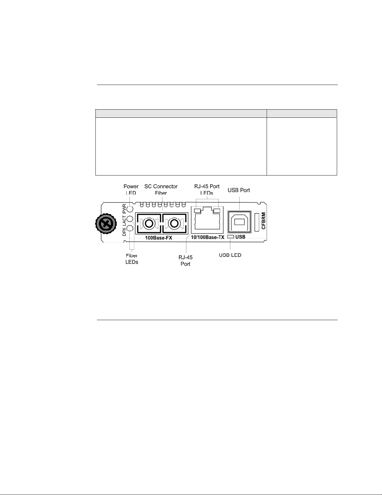
Front panel CFBRM
The front panel of the CFBRM10xx-1xx Devices has the following ports and LEDs:
Ports Front Panel LEDs
One RJ-45 auto-sensing of 10Base or 10/100Base-TX UTP
• Power (one)
• RJ-45 port (two)
connections
One 100Base-FX/LX/BX fiber either SC or ST connectors
• LACT (one)
• DPX (one)
One USB
• USB (one)
Figure 1: Chassis CFBRM10xx-1xx Device Front Panel
Note: The LEDs and ports are the same on the SFBRM10xx-1xx standalone
models.
Continued on next page
24-Hour Technical Support: 1-800-260-1312 International: 00-1-952-941-7600 5
Section I: FBRM/BFFG Product Description Transition Networks
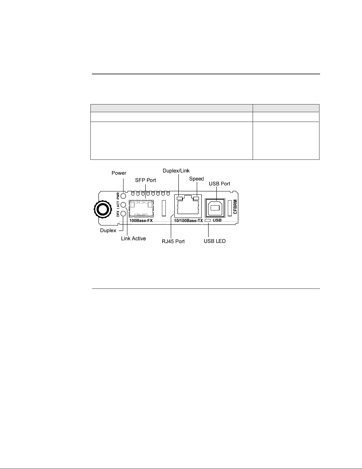
Hardware description, continued
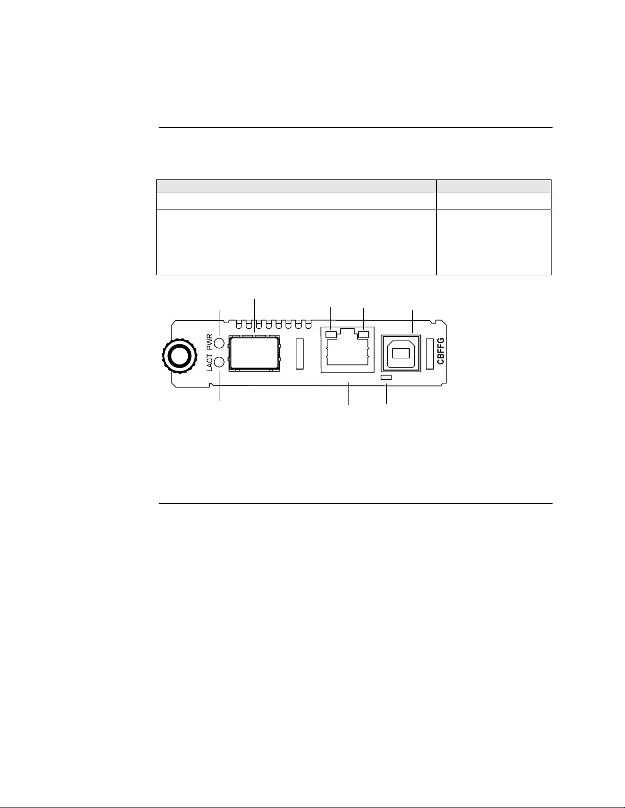
Front panel CFBRM
The front panel of the CFBRM 1040-140 Devices has the following ports and LEDs:
Ports Front Panel LEDs
100Base-FX SFP port
10/100 Base-T copper port
• Power (one)
• Link/Active
• Speed
• Duplex (one)
One USB
• USB (one)
Figure 2: CFBRM1040-100 Front Panel
Note: The LEDs and ports are the same on the SFBRM1040-140 standalone
models.
Continued on next page
6
Transition Networks Section I: FBRM/BFFG Product Description
Hardware description, continued
Front panel CFBRM Gbit
The front panel of the CFBRM13xx-1xx Devices has the following ports and LEDs:
Ports Front Panel LEDs
One 100 Base-T
One 1000Base-FX/LX/BX fiber either SC or ST connectors
One USB
SC Connector
Fiber
100Base-T 1000Base-X
SC Connector
Fiber
USB Port
• Power (one)
• Fiber-Port Link (one)
• Fiber-Port Link (one)
• USB (one)
USBLNKPWR LNK
Power
LED
Fiber Link
LED
Fiber Link
LED
USB LED
Figure 3: Chassis CFBRM13xx-1xx Device Front Panel
Note: The LEDs and ports are the same on the SFBRM13xx-1xx standalone
models.
Continued on next page
24-Hour Technical Support: 1-800-260-1312 International: 00-1-952-941-7600 7
Section I: FBRM/BFFG Product Description Transition Networks
Hardware description, continued
Front panel CBFFG Gbit
The front panel of the CBFFG10xx-1xx Devices has the following ports and LEDs:
Ports Front Panel LEDs
1000Base-SX/LX/BX fiber SC port
10/100/1000Base-T copper port
• Power (one)
• Link/Active
• Speed
• Duplex (one)
One USB
• USB (one)
Figure 4: CBFFG10xx-1xx Device Front Panel
Note: The LEDs and ports are the same on the SBFFG10xx-1xx standalone
models.
Continued on next page
8
Transition Networks Section I: FBRM/BFFG Product Description
Hardware description, continued
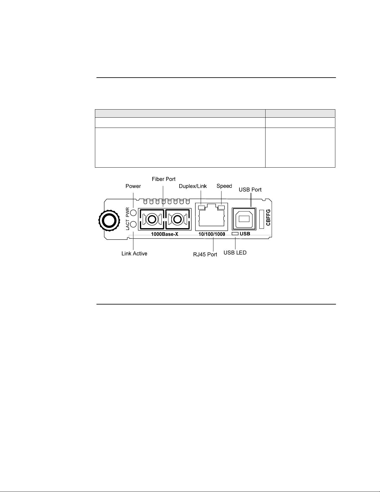
Front panel CBFFG Gbit
The front panel of the CBFFG1040-1xx Devices has the following ports and LEDs:
Ports Front Panel LEDs
1000Base SFP port
10/100/1000Base-T copper port
• Power (one)
• Link/Active
• Speed
• Duplex (one)
One USB
Power
SFP Port
Duplex/Link
Speed
USB Port
• USB (one)
USB
USB LED
Link Active
10/100/10001000Base-X
RJ45 Port
Figure 5: CBFFG1040-1xx Device Front Panel
Note: The LEDs and ports are the same on the SBFFG1040-1xx standalone
models.
Continued on next page
24-Hour Technical Support: 1-800-260-1312 International: 00-1-952-941-7600 9
Section I: FBRM/BFFG Product Description Transition Networks
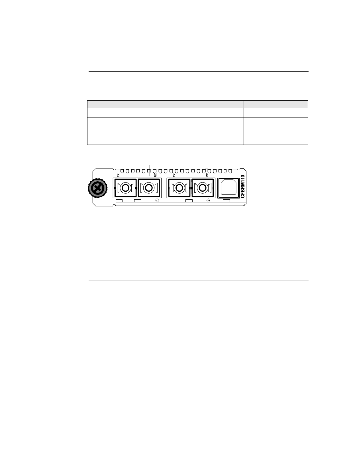
Hardware description, continued
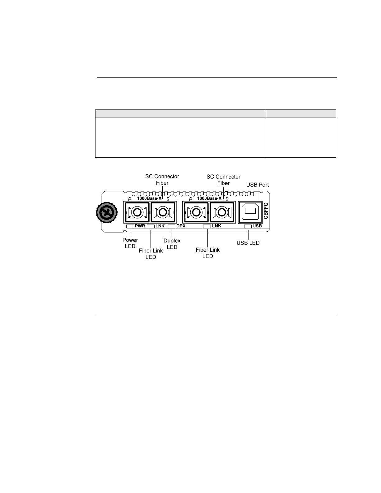
Front panel CBFFG Gbit
The front panel of the CBFFG13xx-1xx Devices has the following ports and LEDs:
Ports Front Panel LEDs
Two 1000Base-FX/LX/BX fiber either SC or ST connectors
• Power (one)
• Fiber-Port Link (two)
• Duplex (one)
One USB
• USB (one)
Figure 6: Chassis CBFFG13xx-1xx Device Front Panel
Note: The LEDs and ports are the same on the SBFFG13xx-1xx standalone
models.
Continued on next page
10
Transition Networks Section I: FBRM/BFFG Product Description
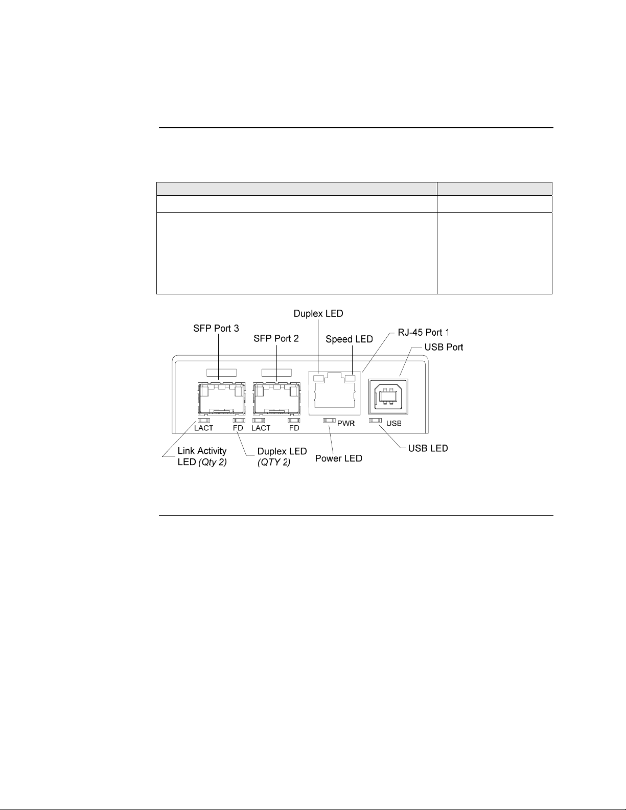
Hardware description, continued
Front panel SFBRM
The front panel of the SFBRM1040-140 redundant Devices has the following ports
and LEDs:
Ports Front Panel LEDs
1000Base SX/LX SFP ports (2 and 3)
• Power (one)
• Link/Active
• Duplex
10/100/1000Base-T copper port (1)
• Speed
• Duplex (one)
One USB
• USB (one)
Figure 7: CBFFG1040-140 Device Front Panel
Continued on next page
24-Hour Technical Support: 1-800-260-1312 International: 00-1-952-941-7600 11
Section I: FBRM/BFFG Product Description Transition Networks
Hardware description, continued
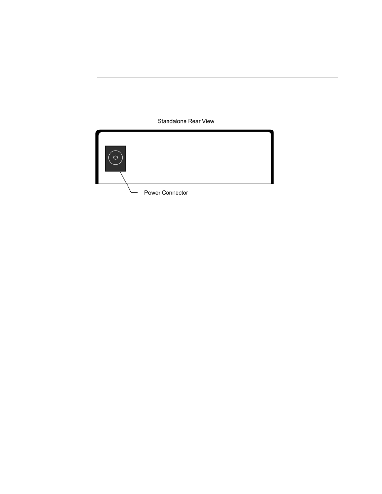
Rear panel (standalone)
On the standalone SFBRM and SBFFG Devices only, the rear panel consists of a
power-barrel connector for connecting power via a power adaptor. See Figure 8.
Figure 8: SFBRM/SBFFG 1xxx-1xx Device Real Panel (Standalone Only)
Note: The Point System chassis powers the CFBRM and CBFFG chassis Devices.
12

Transition Networks Section I: FBRM/BFFG Product Description
FBRM/BFFG13xx-1xx fiber-to-fiber gigabit models
Gigabit (Gbit) models
The FBRM100Base-FX-to-1000Base-X and the BFFG 1000Base-X-to-1000Base-X
are the Gbit versions of the IEEE 802.3ah managed Devices. The BFFG models link
Gbit fiber connections; the FBRM models convert 100Base-Fx 100 Mbit/s to Gbit.
These Devices function generally in the same manner as copper-to-fiber FBRMs, the
difference is the way the ports are configured. See Tables 1 and 2.
Table 1: FBRM13xx-1xx 100Base-FX-to-1000Base-X Device
Port Configuration
Port 1: 100Base-FX
• Default setting: 100Mbs and full duplex.
• FEFI (Far-end fault indication) is configurable.
Port 2: 1000Base-X
Default:
• Auto-Negotiation enabled.
• OAM enabled and in Active Mode if chassis Device
(passive if standalone).
Table 2: BFFG13xx-1xx 1000Base-X-to-1000Base-X Device
Port Configuration
Port 1: 1000Base-X
Port 2: 1000Base-X
Default: Auto-Negotiation enabled.
Default:
• Auto-Negotiation enabled.
• OAM is enabled and in Active Mode if chassis Device
(passive if standalone).
Continued on next page
24-Hour Technical Support: 1-800-260-1312 International: 00-1-952-941-7600 13
Section I: FBRM/BFFG Product Description Transition Networks
FBRM/BFFG13xx-1xx fiber-to-fiber gigabit models, continued
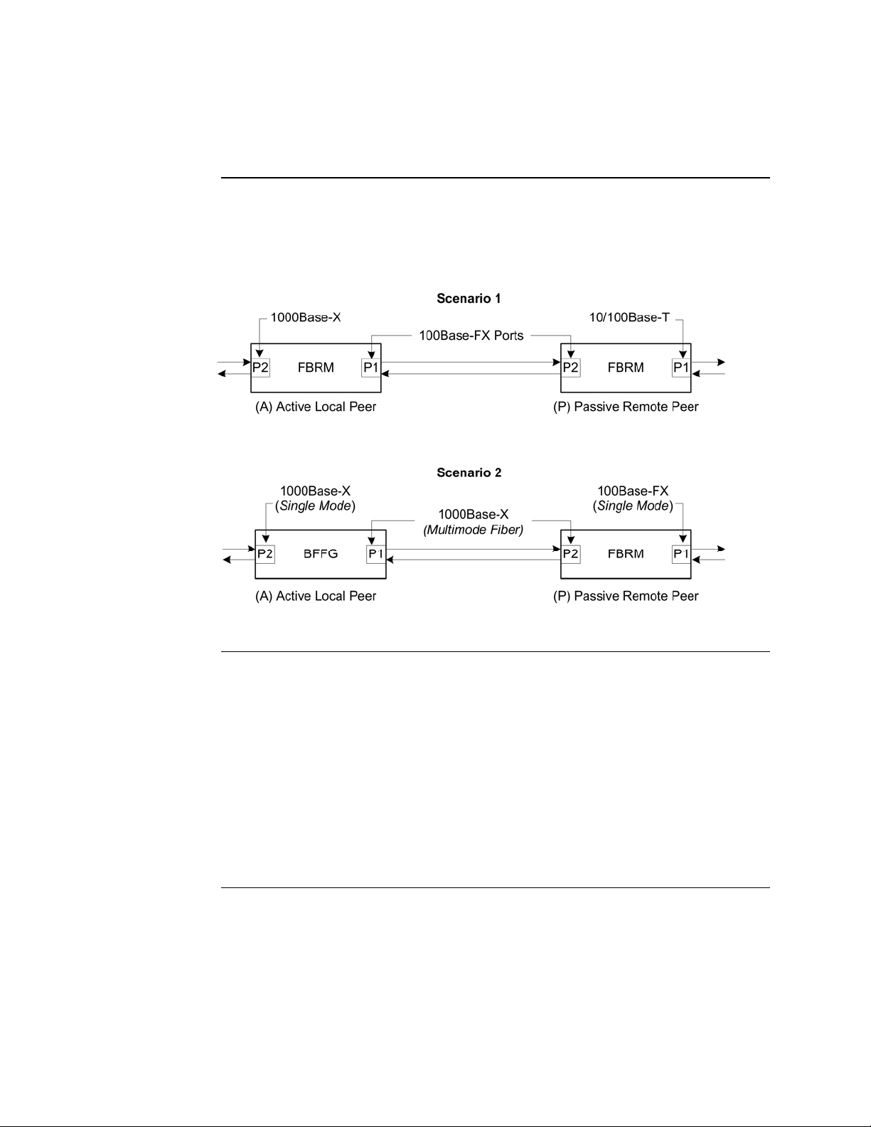
Connectivity
The different versions of the FBRM and BFFG can be connected and set up to
manage a remote peer completely. In a mixed setup with other FBRM or BFFG
Devices, consider the connectivity scenarios in Figure 9, and the explanation that
follows:
Connection scenario explanation
Figure 9: Connectivity Scenarios
In Figure 9, P2 of the active local peer in both scenarios is “OAM enabled” and
“Active” by default. To manage the remote passive peer via OAM, configure P1 of
the active local peer as follows:
• Enable OAM
• Select Active mode
If the connection to the passive remote peer is made thru P2 of the active local peer,
OAM occurs without human intervention.
Note: Automatic firmware upgrades will not occur with different types of FBRM
or BFFG Device configurations.
14
Transition Networks Section I: FBRM/BFFG Product Description
Redundant SFBRM1040-140 models
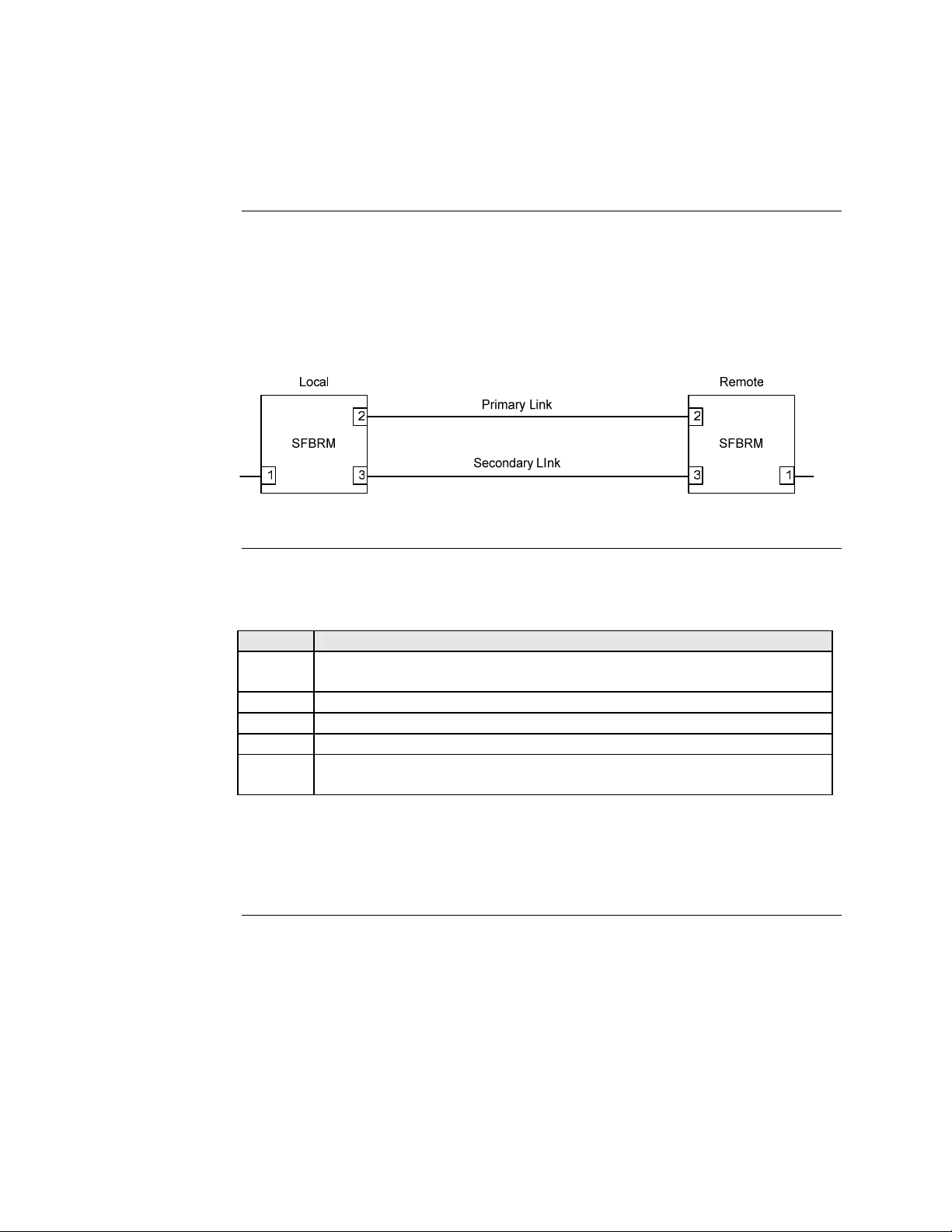
Redundant models
These SFBRM SFP Devices support fiber redundancy. They have two (2) fiber SFP
ports and one (1) copper port. When you tag the fiber ports as primary and secondary
with redundancy enabled, any fault on the primary port results in the secondary port
becoming operational. There is an option for reverting back to the primary once it
has been restored, or you can continue using the secondary port—these are user
selectable features. See Figure 10.
Figure 10: SFBRMs in Redundant Mode
Explanation
With Port 3 as the secondary port in Redundancy Mode and Port 2, the primary goes
down, the following will happen:
Stage Description
A. All Physical layer and OAM configurations of Port 2 will be applied to
Port 3.
B. Port 2 is disabled, and Port 3 initialized to take over.
C. An SNMP trap is sent indicating that the ports have switched.
D. OAM reinitializes (resets all OAM counters and event logs).
E. All the dynamic MAC entries in the ATU are flushed and the active port
has to relearn the entries.
Note: If the configuration option “revert” is set, when the primary port link is
restored the session will revert back to the primary port. If the “revert’ option
is NOT SET and the primary link is restored, the secondary port remains in
operation until the user intervenes.
Continued on next page
24-Hour Technical Support: 1-800-260-1312 International: 00-1-952-941-7600 15
Section I: FBRM/BFFG Product Description Transition Networks
Redundant SFBRM1040-140 models, continued
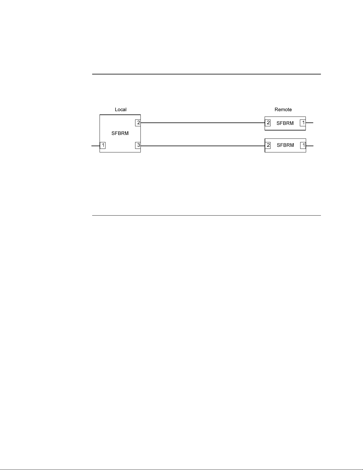
3-port switch mode
In this mode, the Device acts as a 3-port switch with the fiber port connected to 2
remote Devices. See Figure 11.
Figure 11: 3-Port Switch Mode
Note: In 3-port switch mode:
• Only one OAM session can be active at anytime.
• Transparent Link pass through is not applicable in this scenario. The port
link status from the Devices is received only as SNMP traps.
16

Introduction
Caution
In this section
Transition Networks
Section II:
Hardware Installation
This section describes how to install the CFBRM and CBFFG Devices into a Point
System chassis with a remotely managed SFBRM or CFBRM standalone Device.
Also, shows how to install two SFBRM Devices or two SBFFG standalone Devices
on a network, one as a local Device and the other as a remotely managed Device.
When handling chassis Devices observe electrostatic discharge precautions.
This requires proper grounding; i.e., wear a wrist strap. Failure to observe this
caution could result in damage to the chassis Device.
These are the topics:
Topic See Page
Installing CFBRM/CBFFG Devices into a point system chassis 18
Installing SFBRM/SBFFG standalone models 19
Installing copper and fiber cables 20
Connecting power (standalone models) 22
24-Hour Technical Support: 1-800-260-1312 Intern ational: 00-1-952-941-7600 17

Section ll: FBRM/BFFG Hardware Installation Transition Networks
Installing CFBRM/CBFFG Devices into point system chassis
IMPORTANT
Caution
The CFBRM/CBFFG Device product family IS NOT compatible with the CPSMM200 and CPSMM-210 MGMT modules when used in a cascaded application. The
CFBRM/CBFFG can be installed in the “master” chassis with the CPSMM-200
MGMT module, but they can not be installed in a cascaded chassis using the
CPSMM-210 MGMT module.
Alternatively, the CFBRM/CBFFG can be used with the CPSMM120 MGMT
module, which does not support chassis cascading.
Wear a grounding strap and observe electrostatic discharge precautions when
installing the CFBRM/CBFFG Device into the Point System chassis. Failure
to observe this caution could result in damage to the Device.
Chassis Device installation
To install the chassis Device into the Point System chassis, do the following:
Step Action
1. Locate an empty slot in the Point System chassis.
2. Grasp the edges of the Device by its front panel.
3. Align the Device with the slot guides and carefully insert the Device into
the installation slot.
4. Firmly seat the Device against the chassis back panel.
5. Push IN and ROTATE clockwise the panel-fastener screw to secure the
Device to the chassis. See Figure 12.
18
Figure 12: CFBRM/CBFFG Device Chassis Installation
Transition Networks Section ll: FBRM/BFFG Hardware Installation
Installing SFBRM/SBFFG standalone models
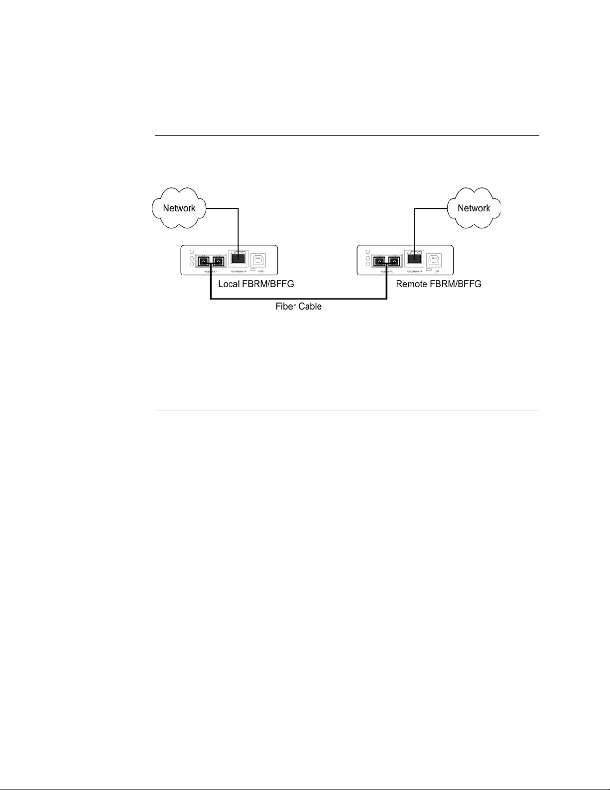
Standalone installation
Figure 13 shows a typical installation involving two (2) SFBRM/SBFFG standalone
Devices on a network.
Figure 13: Installation with Two SFBRM/SBFFG Standalone Devices
Note: With the local active standalone Device connected to a remote standalone
passive Device and with “Mode Control” set to “Auto,” the local (active)
Device will manage the remote (passive) Device. This relationship is
established automatically.
24-Hour Technical Support: 1-800-260-1312 International: 00-1-952-941-7600 19
Section ll: FBRM/BFFG Hardware Installation Transition Networks
Installing fiber and copper cables
Warning
Fiber cable
Use of controls, any adjustments, or the performance of procedures other than
those specified herein may result in hazardous radiation exposure.
Visible and invisible laser radiation when open: DO NOT stare into the laser-
light beam or view the beam directly with optical instruments. Failure to
observe this warning could result in an eye injury or blindness.
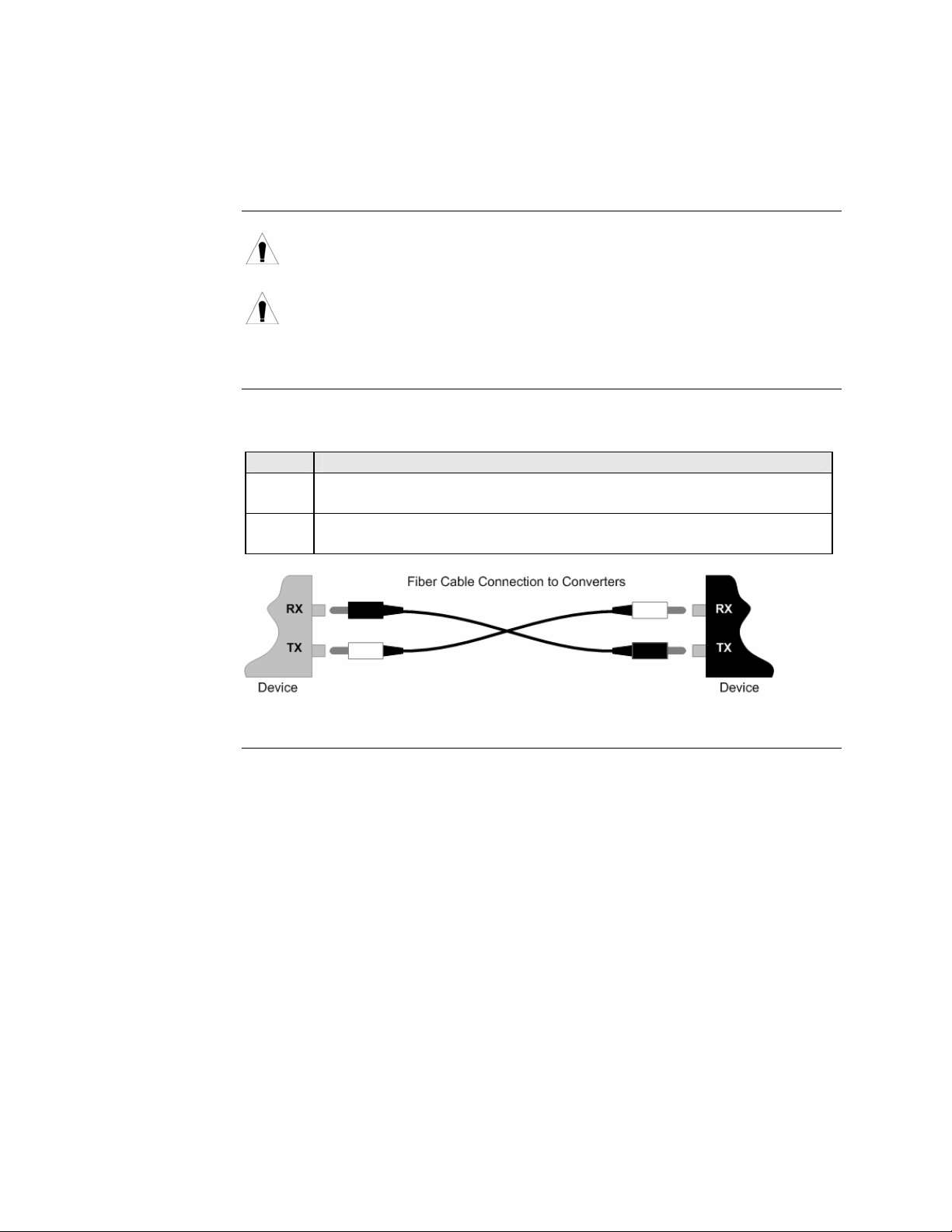
To install the fiber cable, do the following:
Step Action
1. Locate a 100/1000Base-FX/SX/LX compliant fiber cable with male,
two-stranded connectors installed at both ends. See Figure 14.
2. Connect the fiber cables to the FBRM or BFFG Devices as shown in
Figure 14.
Figure 14: Fiber Cable Installation
Continued on next page
20
Transition Networks Section ll: FBRM/BFFG Hardware Installation
Installing fiber and copper cables, continued
Caution
Copper cable
Copper based media ports, e.g., Twisted Pair (TP) Ethernet, USB, RS232,
RS422, RS485, DS1, DS3, Video Coax, etc. are intended to be connected to
intra-building (inside building) link segments that are not subject to lightening
transients or power faults. Failure to observe this caution could result in
damage to equipment.
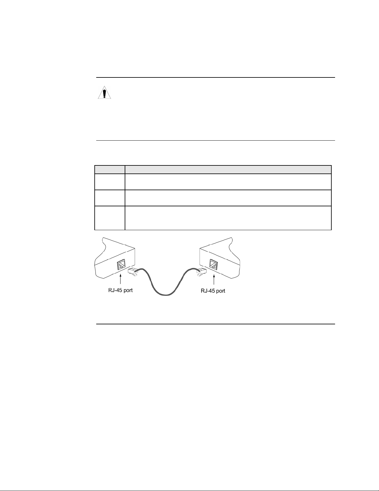
To install the copper cable, do the following:
Step Action
1. Locate a 10/100 or 10/100/1000Base-T compliant copper cable with
male, RJ-45 connectors installed at both ends.
2. Connect the RJ-45 connector at one end of the cable to the Device’s RJ-
45 ports.
3. Connect the RJ-45 connector at the other end of the cable to the 10/100
or 10/100/1000Base-T RJ-45 port on the other Device (switch,
workstation, etc.). See Figure 15.
Figure 15: Copper Cable Installation
24-Hour Technical Support: 1-800-260-1312 International: 00-1-952-941-7600 21

Section ll: FBRM/BFFG Hardware Installation Transition Networks
Connecting power (standalone models)
Chassis powers slide-in Device
Adapter powers standalone
Transition Networks’ Point System chassis powers the CFBRM/CBFFG chassis
Devices.
Use an AC power adaptor to power the SFBRM/SBFFG standalone Device. To
connect power to the Device, do the following:
Step Action
1. Connect the barrel connector on the power adapter cord to the power
connector on the Device (located on the rear of the Device).
See Figure 16.
Figure 16: Standalone Device Power Connector
2. Connect the power adapter plug into AC power.
3. Verify that the Device has powered UP—the power indicator LED will be
lit.
22

Transition Networks Section ll: FBRM/BFFG Hardware Installation
Intentionally Blank
24-Hour Technical Support: 1-800-260-1312 International: 00-1-952-941-7600 23

Transition Networks
Section III:
USB Driver Installation & COM Port Setup
Introduction
In this section
This section shows how to install the USB driver and configure COM ports.
These are the topics:
Topic See Page
Installing USB driver 25
Configuring COM ports 29
24-Hour Technical Support: 1-800-260-1312 Intern ational: 00-1-952-941-7600 24

Transition Networks Section lll: FBRM/BFFG1 Driver Installation & COM Port Setup
Installing USB driver
USB driver
Installing USB driver
The driver installation instructions are for Windows XP only. Installing the USB
driver using Windows 2000 is similar, but not necessarily identical to the following
Windows XP driver-installation procedure.
Note: The following USB drivers are provided with the product on a CD, also
available at
www.ftdichip.com (click on drivers): WinXP64, Win Server
2003, Win 2002, Win ME/98, Mac OS X, 9, 8, and Linux.
To install the USB driver on a computer with a Windows XP OS, do the following:
Step Action
1. Extract the driver (provided CD or from website) and place it in an
accessible folder on the local drive.
2. Plug the Device into the USB port on the PC to bring up the “found new
hardware” wizard dialog box, shown in Figure 17.
3. Select RADIO button, “No, not this time” as shown in Figure 17.
Figure 17: Found New Hardware Wizard Dialog Box
Continued on next page
24-Hour Technical Support: 1-800-260-1312 International: 00-1-952-941-7600 25

Section lll: FBRM/BFFG USB Driver Installation & COM Port Setup Transition Networks
Installing USB driver, continued
Installing USB driver (continued)
Step Action
4. Click the NEXT button to launch the “installation options” dialog box.
5. Select RADIO button “Install from a list or specific location
(Advanced)” as shown in Figure 18.
Figure 18: Installation Options Dialog Box
6. Click the NEXT button to bring up the “driver search installation
options” dialog boxes shown in Figure 19.
Figure 19: Driver Search Installation Options Dialog Box
Continued on next page
26

Transition Networks Section lll: FBRM/BFFG1 Driver Installation & COM Port Setup
Installing USB driver, continued
Step Action
7. Use the BROWSE button to locate the USB driver, as shown in
Figure 20.
C:\FBRM/BFFG1xx
Figure 20: Driver Location
8. Click the NEXT button to start installing the driver and the driver-install
screen will appear as XP copies the Device driver. See Figure 21.
FBRM/BFFG1xx Driver
Figure 21: Windows XP Installing Driver Box
Continued on next page
24-Hour Technical Support: 1-800-260-1312 International: 00-1-952-941-7600 27

Section lll: FBRM/BFFG USB Driver Installation & COM Port Setup Transition Networks
Installing USB driver, continued
Step Action
9. After the driver installation is successful, the “finished installing” dialog
box will appear, as shown in Figure 22.
Figure 22: Finish Installing Driver Dialog Box
10. Click the FINISH button and a “found new hardware” message will
appear on the lower right side of the screen, as shown in Figure 23.
Figure 23: New Hardware Installed and Ready to Use
28
Transition Networks Section lll: FBRM/BFFG1 Driver Installation & COM Port Setup
Configuring COM port
Getting COM port number
You need the COM port number to configure the terminal emulator. To get the COM
port number, do the following:
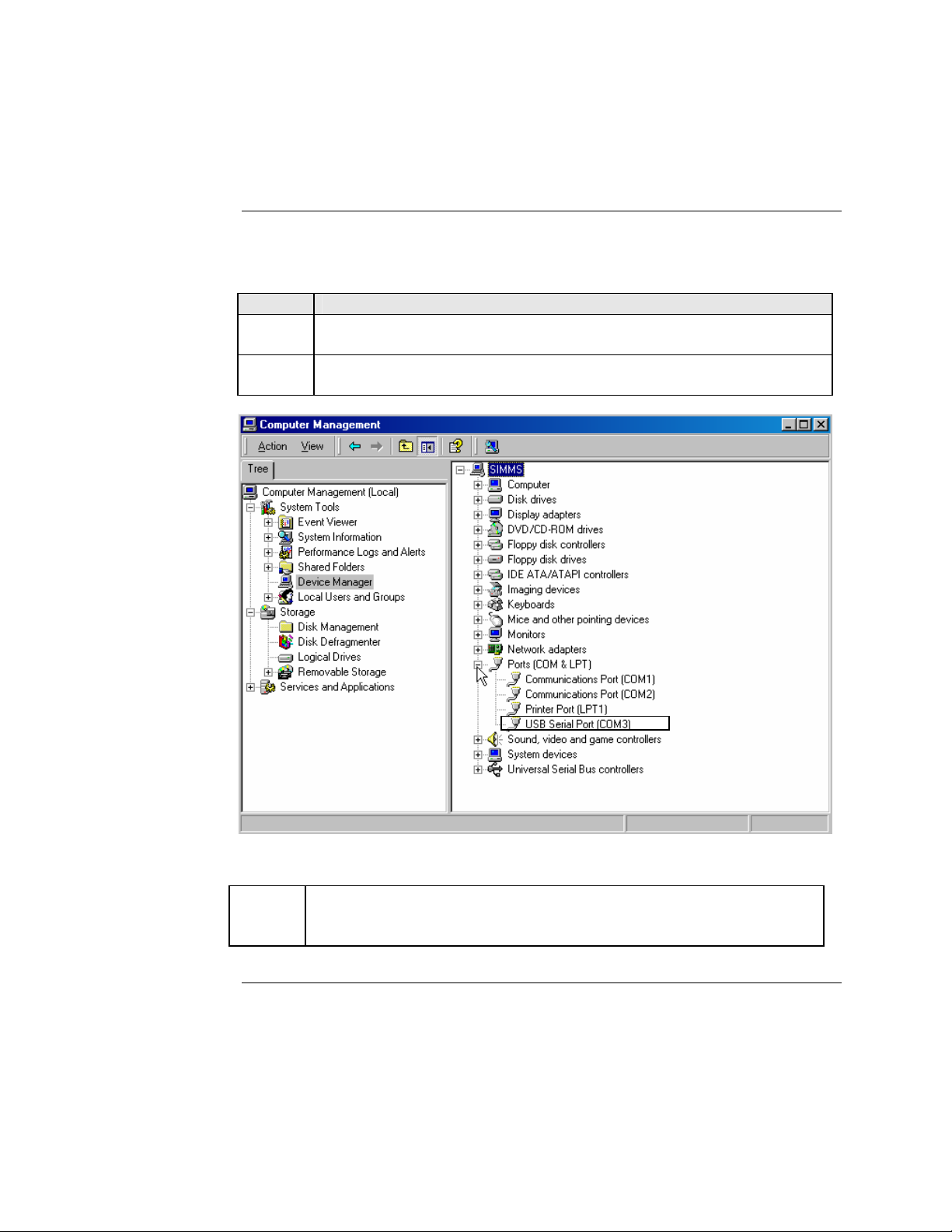
Step Action
1. On the desktop, right click on the “my computer” icon and select
“Device manager” to open the “computer management” window.
2. Click on “Device manager” to open the Device manager’s panel (screen
right panel) shown in Figure 24.
Figure 24: Computer Management Window
3.
Expand the Ports (COM & LPT) in the right column and write down the
USB COM port number for configuring the terminal emulator software
used for the USB Device.
Continued on next page
24-Hour Technical Support: 1-800-260-1312 International: 00-1-952-941-7600 29

Section lll: FBRM/BFFG USB Driver Installation & COM Port Setup Transition Networks
Configuring COM port, continued
Terminal emulator setup
To set up the terminal emulator software, e.g., HyperTerminal to use the USB COM
port, do the following:
Step Action
1. Activate the “HyperTerminal” software to bring up the “connection
description” dialog box, shown in Figure 25.
Figure 25: Connexion Description Diallo Box
2. Type in a name and select an icon.
3. Click the OK button to launch the “connect to” dialog box, shown in
Figure 26.
Figure 26: Connect To Dialog Box
Continued on next page
30

Transition Networks Section lll: FBRM/BFFG1 Driver Installation & COM Port Setup
Configuring COM port, continued
Terminal emulator setup (continued)
Step Action
4. Select the COM port identified for the USB Device shown in the Device
manager.
5. Click the OK button to bring up the “port settings” dialog box, shown in
Figure 27.
Figure 27: COM Port Settings Dialog Box
6. Set the COM port properties as follows:
• Baud: 57600
• Data length: 8
• Parity: None
• Stop bit: 1
• Flow Control: None
7. Click the OK button and the Device login prompt will appear.
24-Hour Technical Support: 1-800-260-1312 International: 00-1-952-941-7600 31

Introduction
Transition Networks
Section live:
Initial Device Setup
There are four ways to set up the FBRM/BFFG 1xxx-1xx Devices before the Device
can be operated and managed:
• USB CLI
• Telnet
• Chassis MMU (chassis model)
• IP-based (directly to FBRM/BFFG)
The factory default IP configuration is the following:
• IP address: 192.168.1.1
• Subnet Mask: 255.255.255.0
• Gateway: 192.168.1.2
In this section
These are the topics:
Topic See Page
USB CLI access 33
Initial Device setup via USB CLI 35
Initial Device setup via Telnet (directly to Device) 38
Initial Device setup via chassis agent (MMU) web-based 41
Initial Device setup via IP web-based (directly to Device) 44
24-Hour Technical Support: 1-800-260-1312 Intern ational: 00-1-952-941-7600 32

Transition Networks Section lV: FBRM/BFFG Initial Device Setup
USB CLI access
Accessing the USB CLI
To access the USB CLI, do the following:
Step Action
1. Connect the Device to a computer via the USB port.
2. Activate the terminal emulator software to launch the emulator screen.
3. Press the ENTER key to bring up the “password” prompt.
4. Enter the password and then the login (default is “root” in both cases) to
bring up the Device console> prompt, shown in Figure 28.
Password :
Login : root
Password :
Console:/>_
Figure 28: Device Console Prompt
5.
To access the commands list, at the console> prompt type help or “?”
6. Press the ENTER key to launch the “commands” screen, shown in
Figure 29.
Figure 29: Commands for FBRM/BFFGs Models
Note: See Appendix C for a complete list of the configuration commands and
definitions. All CLI commands are case sensitive.
Continued on next page
24-Hour Technical Support: 1-800-260-1312 International: 00-1-952-941-7600 33

Section IV: FBRM/BFFG Initial Device Setup Transition Networks
USB CLI access, continued
Redundant
The following is the screen of commands for the redundant SFP Devices.
Figure 30: Commands for Redundant SFP Models
34

Transition Networks Section lV: FBRM/BFFG Initial Device Setup
Initial Device setup via USB CLI
IP configuration
Factory default IP config
Use the ‘set’ commands to set the IP configuration through the USB port. Configure
the Device with a network IP address, subnet mask, and default gateway. Set the IP
address via USB CLI (Command Line Interface), or via DHCP (Dynamic Host
Configuration Protocol), which is disabled by default.
The factory default IP configuration shipped with the Device is as follows:
• IP address: 192.168.1.1
• Subnet Mask: 255.255.255.0
• Gateway: 192.168.1.2
Note: Type “help set <command>” to display the format used to set the commands.
Set IP config via USB CLI
To set the IP via the USB CLI, do the following:
Step Action
At the console> prompt type set ip=nnn.nnn.nnn.nnn
1.
2. Press the ENTER key to set the IP address.
At the console> prompt type set netmask=nnn.nnn.nnn.nnn
3.
4. Press the ENTER key to set the netmask.
At the console> prompt type set gateway=nnn.nnn.nnn.nnn
5.
At the console> prompt type save
6.
7. Press the ENTER key to save the new IP configuration.
Continued on next page
24-Hour Technical Support: 1-800-260-1312 International: 00-1-952-941-7600 35

Section IV: FBRM/BFFG Initial Device Setup Transition Networks
Initial Device setup via USB CLI, continued
DHCP method
To set the IP configuration via the DHCP in console mode, do the following:
Note: A DHCP server must be on the network and accessible before using this
method.
Step Action
At the console> prompt type set dhcp=enable
1.
2. Press the ENTER key and the screen will appear as shown in Figure 31.
Figure 31: Enable DHCP
Type reboot
3.
4. Press the ENTER key to reboot the Device and start the DHCP process.
Note: DHCP “successful” will appear on the screen when completed, or “failed” if
not successful.
Continued on next page
36
Transition Networks Section lV: FBRM/BFFG Initial Device Setup
Initial Device setup via USB CLI, continued
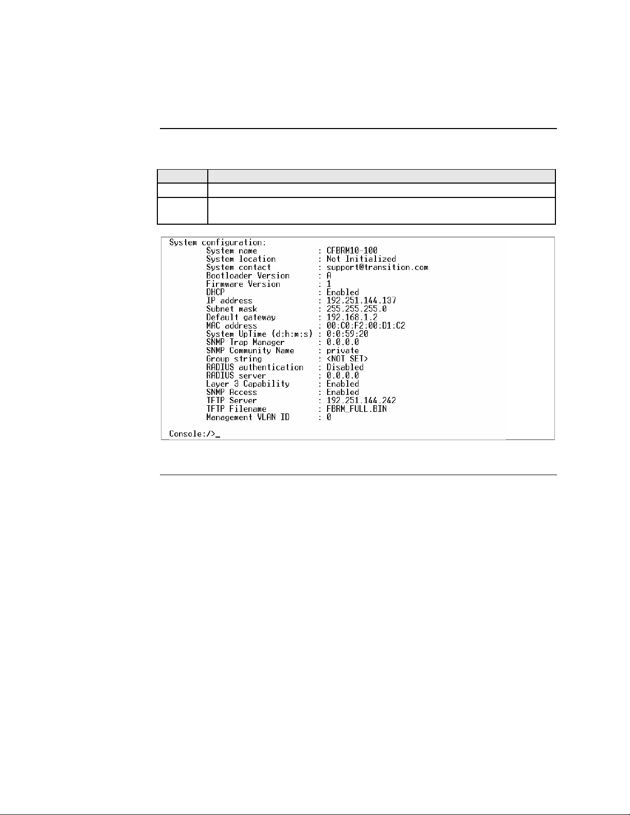
Show system configuration
To show the Device system configuration, do the following:
Step Action
1.
At the console> prompt type show
2. Press the ENTER key to bring up the Device system configuration screen,
shown in Figure 32.
Figure 32: Example System Configuration Screen
24-Hour Technical Support: 1-800-260-1312 International: 00-1-952-941-7600 37
Section IV: FBRM/BFFG Initial Device Setup Transition Networks
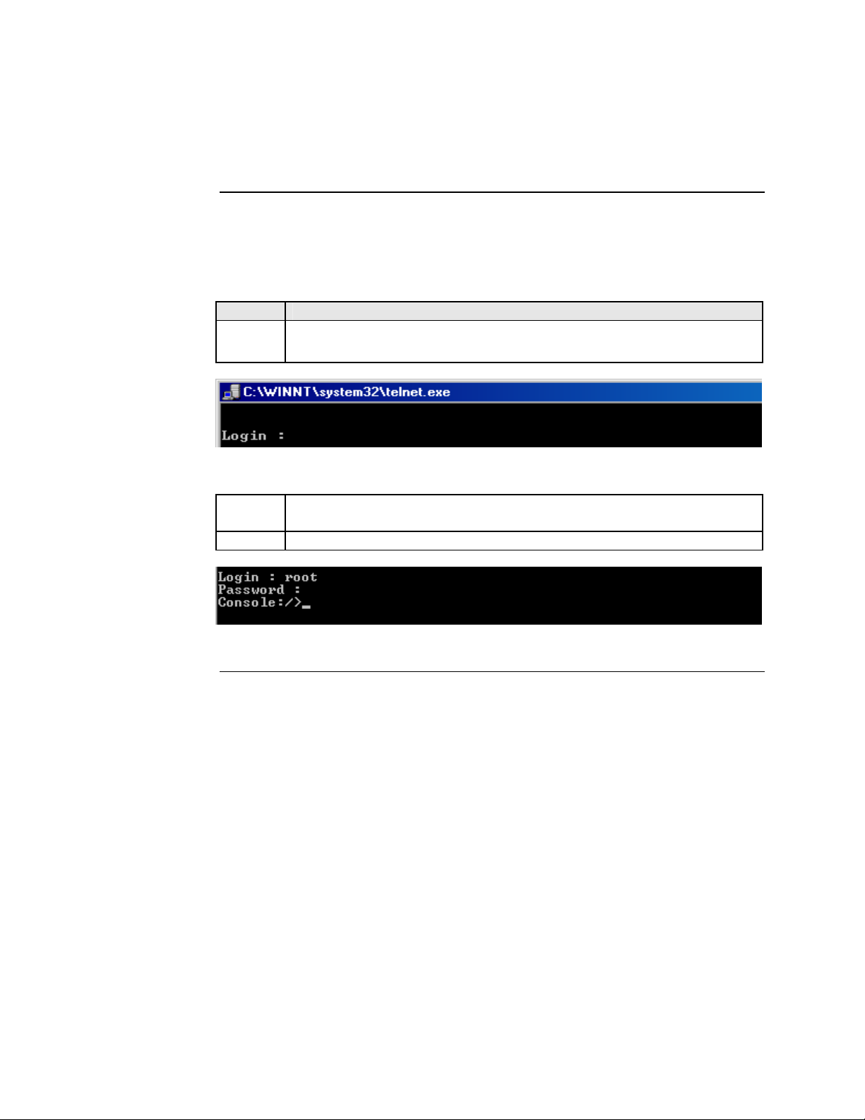
Initial Device setup via telnet (directly to Device)
To set up the Device initially via telnet directly to the Device, do the following:
Initial setup via Telnet to Device
Step Action
1.
At the command line type: Telnet nnn.nnn.nnn.nnn (IP address of the Device) to
bring up the password prompt, shown in Figure 33.
Figure 33: Password Prompt
Type the case-sensitive username and password (default is ‘root’ for
2.
both).
3. Press the ENTER key to launch the console prompt, shown in Figure 34.
Figure 34: Console Prompt
Continued on next page
38
Transition Networks Section lV: FBRM/BFFG Initial Device Setup
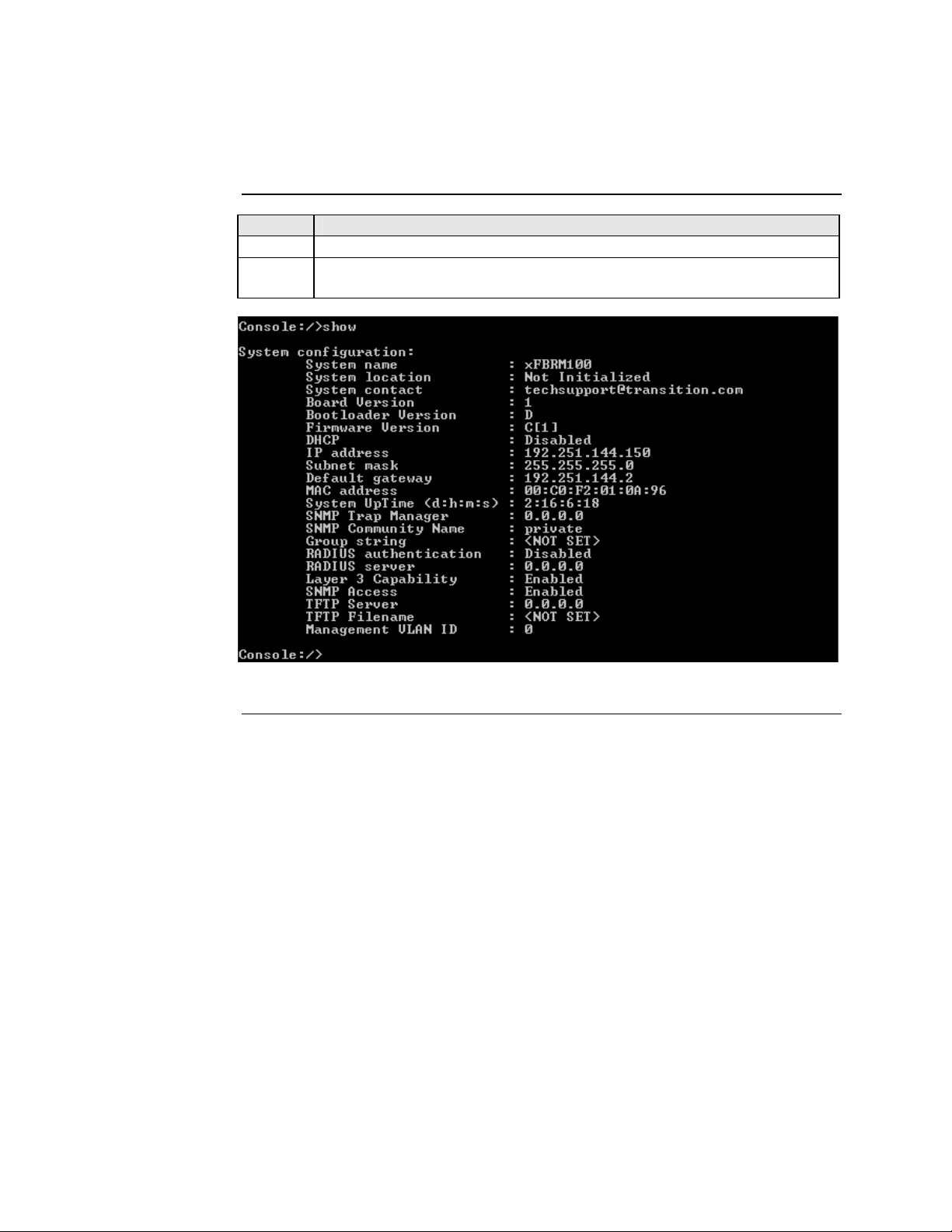
Initial Device setup via telnet (directly to Device), continued
Step Action
At the console:/> prompt type show
4.
5. Press the ENTER key to display the system configuration, as shown in
Figure 35.
Figure 35: System Configuration Screen
Continued on next page
24-Hour Technical Support: 1-800-260-1312 International: 00-1-952-941-7600 39

Section IV: FBRM/BFFG Initial Device Setup Transition Networks
Initial Device setup via telnet (directly to Device), continued
Step Action
6.
At the console prompt type: help
7.
Press the ENTER key to show the commands, shown in Figure 36.
Terminating
telnet
Figure 36: Device Command Screen
Note: The CLI and Telnet interface commands are structured in the same manner.
To disconnect the Telnet client from the management module server, press the
CTRL-D keys, or at the console prompt type: exit or logoff
40
Transition Networks Section lV: FBRM/BFFG Initial Device Setup
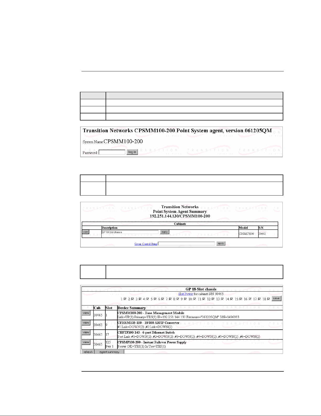
Initial Device setup via chassis agent MMU, web-based
Setup via Web to MMU
To set up the Device initially via the MMU web-based, do the following:
Step Action
1. Open a web browser.
2. At the URL type the IP address of the chassis (MMU).
3. Click the GO button to bring up the password screen, shown in Figure 37.
Figure 37: Chassis Agent (MMU) Log In Screen
Type the password (default is private). 4.
5. Press the ENTER key to launch the chassis agent’s main menu, shown in
Figure 38.
Figure 38: Chassis Agent (MMU) Main Menu
6. Click the VIEW button to show the Devices in the chassis and the screen
will appear, as shown in Figure 39.
Figure 39: Point System Chassis Main Menu
Continued on next page
24-Hour Technical Support: 1-800-260-1312 International: 00-1-952-941-7600 41

Section IV: FBRM/BFFG Initial Device Setup Transition Networks
Initial Device setup via chassis agent MMU, web-based, continued
Step Action
7. Click the VIEW button of the CFBRM/CBFFG Device in slot 9 to show
the local configuration screen for the Device. See Figure 40.
Note: You can configure the IP along with other Device parameters on this screen.
42
Figure 40: Local Switch FBRM/BFFG Configuration Screen
Note: DO NOT use the browser BACK button to navigate the screens. This will
cause the connection to drop.
Continued on next page

Transition Networks Section lV: FBRM/BFFG Initial Device Setup
Initial Device setup via chassis agent MMU, web-based, continued
IP config via DHCP
To configure the IP via DHCP, do the following:
Step Action
1. A DHCP server must be on the network and accessible.
2. On the local switch configuration screen, enable DHCP.
3. On the local switch configuration screen set item Reset Switch to “Yes.”
4. Click the SAVE/EXECUTE button to start the DHCP process.
Note: To verify that the DHCP IP configuration was successful, check the IP
configuration for the Device on the local switch screen and note the changes
to the IP configuration.
24-Hour Technical Support: 1-800-260-1312 International: 00-1-952-941-7600 43
Section IV: FBRM/BFFG Initial Device Setup Transition Networks
Initial Device setup IP web-based (directly to Device)
Initial setup via IP to Device
To set up the Device initially via a IP web-based, do the following:
Step Action
1. Open a web browser.
2. At the URL type in the FBRM/BFFG default IP address.
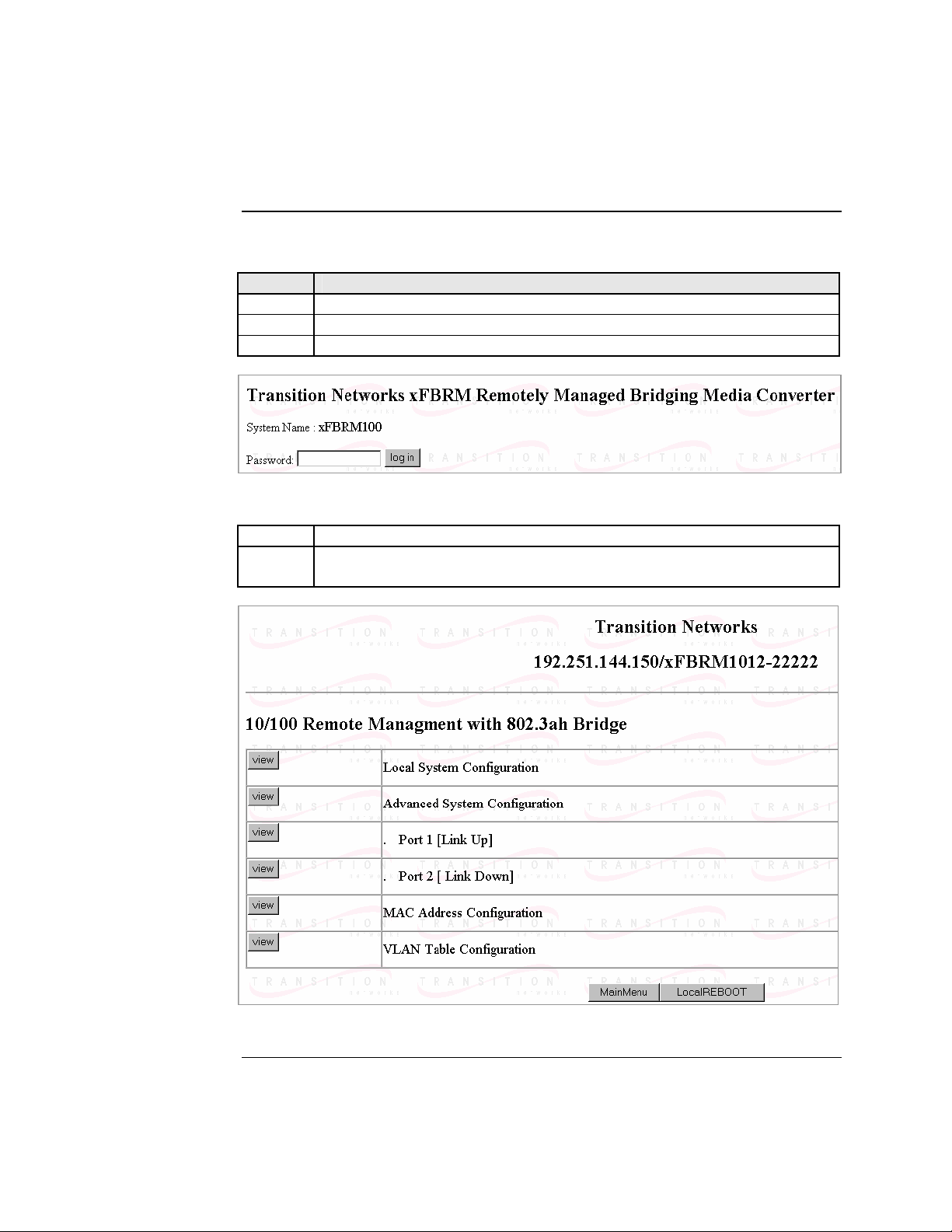
3. Click the GO button to launch the password screen shown in Figure 41.
Figure 41: Login Screen
Type the password (default is private). 4.
5. Press the ENTER key to launch the FBRM/BFFG main menu, as shown
in Figure 42.
44
Figure 42: FBRM/BFFG Main Menu
Continued on next page
Transition Networks Section lV: FBRM/BFFG Initial Device Setup
Initial Device setup IP web-based (directly to Device), continued
Step Action
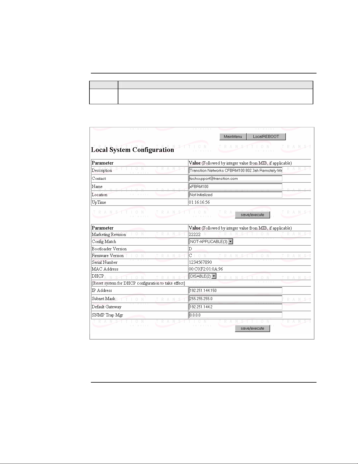
6. Click the local system configuration VIEW button to show the local
system configuration menu, shown in Figure 43.
Note: You can configure the IP along with other Device parameters on this screen.
Figure 43: FBRM/BFFG Local System Configuration Screen
Note: DO NOT use the browser BACK button to navigate the screens. This will
cause the connection to drop.
Continued on next page
24-Hour Technical Support: 1-800-260-1312 International: 00-1-952-941-7600 45

Section IV: FBRM/BFFG Initial Device Setup Transition Networks
Initial Device setup IP web-based (directly to Device), continued
IP config via DHCP
To set up the IP configuration via DHCP, do the following:
Step Action
1. A DHCP server must be on the network and accessible.
2. On the local switch configuration screen, enable DHCP as shown in Figure
44.
46
Figure 44: IP-based Local System Configuration Screen
3. Click the Local REBOOT button at the top of the screen to start the DHCP
process.
Note: To verify that the DHCP IP configuration was successful, check the IP
configuration for the Device on the local system configuration screen and
note the changes to the IP configuration.
Continued on next page

Transition Networks Section lV: FBRM/BFFG Initial Device Setup
Initial Device setup IP web-based (directly to Device), continued
Redundant Devices
To set up the redundant feature for the stand-alone 3-port FBRM SFP Device via IP
web-based, do the following:
Step Action
1. Open a web browser.
2. At the URL type in the SFBRM default IP address.
3. Click the GO button to launch the password screen shown in Figure 45.
Figure 45: Login Screen
Type the password (default is private). 4.
5. Press the ENTER key to launch the SFBRM main menu, as shown in
Figure 46.
Figure 46: Redundant Device Main Menu
Continued on next page
24-Hour Technical Support: 1-800-260-1312 International: 00-1-952-941-7600 47

Section IV: FBRM/BFFG Initial Device Setup Transition Networks
Initial Device setup IP web-based (directly to Device), continued
Step Action
6. Click the advance system configuration VIEW button to show the
redundancy configuration parameters, shown in Figure 47.
48
Figure 47: Redundancy Configuration Screen
Note: The redundancy features are specific to the 3-port SFBRM SFP Device
only.

In this section
Transition Networks
Sections V:
Device Management
These are the topics:
Topic See Page
SNMP IP-based management 50
Device management via chassis MMU web-based 53
Device management via IP (directly to Device) 56
24-Hour Technical Support: 1-800-260-1312 Intern ational: 00-1-952-941-7600 49

Section V: FBRM/BFFG Device Management Transition Networks
SNMP IP-based management
SNMP
The FBRM/BFFG Device provides complete management through the SNMP
interface. It supports the following standard MIBs for management, using SNMPv1:
• RFC 1213 (MIB- II)
• RFC 2819 (RMON – statistics group)
• RFC 2863 (IF MIB counters)
• RFC 3635 (Ether-like MIB counters)
• RFC 1493 (Bridge MIB objects counters)
• RFC 2674 (Bridge extension counters)
I-D: draft-ietf-hubmib-efm-mib (EFM OAM mib – the EFM hub mib is added to the
TN private tree since it has not been added to the ISO tree.) Use the provide version
shipped on the CD with your Device.
See Figure 48.
EFM-Hub MIBs
Figure 48: EFM Hub MIBs Added to Private Tree
Continued on next page
24-Hour Technical Support: 1-800-260-1312 International: 00-1-952-941-7600
50

Transition Networks Section V: FBRM/BFFG Device Management
SNMP IP-based management, continued
TN private MIBs
The TN private MIBs for SNMP IP-based management feature extensive
management options. Some of the features are the following:
• Copper and fiber link status
• Copper and fiber port duplex
• Administratively enable/disable port
• Copper port speed
• Enable/disable Auto-Negotiation (copper)
• Enable/disable Pause
• Enable/disable capability advertisement for speed and duplex
• RMON statistics
• AutoCross on copper port
• Remote fault detect
• Enable/disable far-end fault on fiber
• Transparent link-pass through
• 802.3ah OAM enable/disable on all ports
• OAM channel statistics
• OAM remote loopback
• Rate limiting/band width allocation using fixed rate sets
• IP traffic class priority
• 802.1q VLAN support
• Virtual cable test
The remote Device can be managed completely through OAM. Figure 49 shows an
example of a private MIB objects tree.
Continued on next page
24-Hour Technical Support: 1-800-260-1312 International: 00-1-952-941-7600 51

Section V: FBRM/BFFG Device Management Transition Networks
SNMP IP-based management, continued
MIB objects
Figure 49 shows the placement of the MIB objects on the private tree.
Private MIB Objects
Figure 49: Private MIB Objects
24-Hour Technical Support: 1-800-260-1312 International: 00-1-952-941-7600
52
Transition Networks Section V: FBRM/BFFG Device Management
Device management via chassis agent (MMU) web-based
Management via MMU
To set up the FBRM/BFFG initially via the MMU, do the following:
Step Action
1. Open a web browser.
2. At the URL type the IP address of the chassis (MMU).
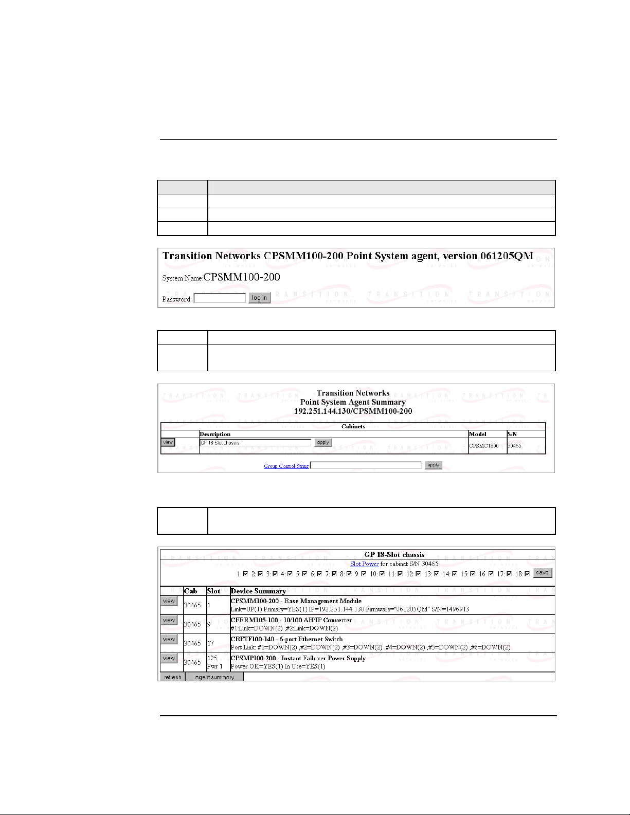
3. Click the GO button to launch the password screen. See Figure 50.
Figure 50: Chassis Agent (MMU) Login Screen
Type the password (default is private). 4.
5. Press the ENTER key to launch the chassis agent’s main menu, as shown
in Figure 51.
Figure 51: Chassis Agent (MMU) Main Menu
6. Click the VIEW button to show the Devices in the cabinet slots, as shown
in Figure 52.
Figure 52: Devices in Chassis Slots
Continued on next page
24-Hour Technical Support: 1-800-260-1312 International: 00-1-952-941-7600 53

Section V: FBRM/BFFG Device Management Transition Networks
Device management via chassis agent (MMU) web-based, continued
Step Action
7. Click the VIEW button of the CFBRM/CBFFG Device to bring up the
local switch management screen. See Figure 53.
Figure 53: Local Switch Configuration Screen
8. Scroll down to the LOCAL PORT buttons, shown in Figure 54.
Figure 54: Local System Configuration Local Port Buttons
Note: DO NOT use the browser BACK button to navigate the screens. This will
cause the connection to drop.
Continued on next page
24-Hour Technical Support: 1-800-260-1312 International: 00-1-952-941-7600
54

Transition Networks Section V: FBRM/BFFG Device Management
Device management via chassis agent (MMU) web-based, continued
Step Action
9. Click a PORT BUTTON to bring up the local port switch configuration
screen, shown in Figure 55.
10. Scroll down the screen to see the remaining parameters.
Note: You can set OAM and other parameters on this screen.
Figure 55: Port 1 Local Switch
Note: DO NOT use the browser BACK button to navigate the screens. This will
cause the connection to drop.
24-Hour Technical Support: 1-800-260-1312 International: 00-1-952-941-7600 55

Section V: FBRM/BFFG Device Management Transition Networks
Device management via IP web-base (directly to Device)
Introduction
IP web-based management
The FBRM/BFFG Device supports complete Web-based management for viewing
statistics and configuring the Device. See the help file on Transition Networks
website for more details about different configuration variables.
To manage the Device via the IP web-based, do the following:
Step Action
1. Open a web browser.
2. At the URL type the IP address of the Device.
3. Click the GO button to bring up the password screen, shown in Figure 56.
Enter the password (default password is “private”). 4.
Figure 56: Device Password Screen
Note: DO NOT use the browser BACK button to navigate the screens. This will
cause the connection to drop.
Continued on next page
24-Hour Technical Support: 1-800-260-1312 International: 00-1-952-941-7600
56

Transition Networks Section V: FBRM/BFFG Device Management
Device management via IP web-base (directly to Device), continued
IP web-based management (continued)
Step Action
5. Click the LOG IN button to bring up the main menu of the Device. See
Figure 57.
Note: Any Transition Networks FBRM/BFFG remote peer can be completely
managed by an FBRM/BFFG local peer through OAM.
Figure 57: FBRM/BFFG Main Menu
Note: DO NOT use the browser BACK button to navigate the screens. This will
cause the connection to drop.
Continued on next page
24-Hour Technical Support: 1-800-260-1312 International: 00-1-952-941-7600 57

Section V: FBRM/BFFG Device Management Transition Networks
Device management via IP web-base (directly to Device), continued
OAM configuration
The OAM configuration screen allows enabling or disabling OAM by setting the
mode to “active” or “passive.” If the remote Device is a Transition Networks
FBRM/BFFG Device, the main menu (PORT button with the remote Device
connected) will show the options for managing the remote OAM peer.
The Devices are interoperable with other IEEE 802.3ah compliant Devices. Standard
OAM discovery, loopback, dying gasp, link and other critical events are supported.
The OAM configuration screen for that port will show the following:
• OAM state
• MAC address
• OUI (unique identifier)
Note: On the SFBRM1040-1xx redundant models, there can be only one (1) OAM
session at a time—the OAM enabled port is user selected. Port 2 fiber is the
default port.
OAM config screen
To view the OAM configuration screen for non-transition networks IEEE 802.3ah
compliant Devices, do the following:
Step Action
1. Click any port VIEW button on the CFBRM/CBFFG main menu to bring
up configure screen of that port.
2. Click the OAM Config button and the screen will appear, as shown in
Figure 58.
3. You can set up OAM parameters on this screen.
Figure 58: OAM Configuration and Status Screen (OAM Config Button)
24-Hour Technical Support: 1-800-260-1312 International: 00-1-952-941-7600
58

Introduction
In this section
Transition Networks
Section VI:
Software Features
This section explains the operational status LEDs and what they indicate, along with
product features, and the three (3) methods used to upgrade the software.
These are the topics:
Topic See Page
Software feature descriptions 60
Software security feature descriptions 69
24-Hour Technical Support: 1-800-260-1312 Intern ational: 00-1-952-941-7600 59

Section Vl: FBRM/BFFG Software Features Transition Networks
Software feature descriptions
Note: The FBRM/BFFG Devices does not have configuration switches.
Firmware activated features
The FBRM/BFFG series Devices features can be configured via USB, MMU, or IP.
Table 3 explains the configurable parameters of the Devices.
Table 3: Device Software Configurable Features
Feature Description
AutoCross When the AutoCross feature is active, it allows the use
(10/100Base-T or
10/100/1000Base-T)
of a straight-through (MDI) or crossover (MDI-X)
copper cable when connecting to 10/100Base-T or
10/100/1000Base-T Devices. AutoCross determines the
characteristics of the connection and configures the
Devices to link up automatically. This occurs regardless
of the cable configuration: MDI or MDI-X. (Transition
networks recommends leaving AutoCross in default
mode, “enabled.”)
Automatic Firmware
Upgrades
The Device has an automatic firmware upgrade feature.
This feature applies to a communication link between a
local peer and its remote peer Devices connected via a
fiber optic cable. If the remote passive peer Device is not
in Active Mode and a local active peer Device detects a
different firmware revision on its remote passive peer
Device, the local active Device will force a bootload
condition and download its firmware revision to its
remote passive peer Device.
Note The local Device could have a different firmware
revision (newer or older) than its remote peer. In
either case, the firmware revision on the local
Device will replace that of its remote passive
peer.
Note: The firmware of the local active peer Device
should be upgraded before the remote passive
peer Device to ensure that the correct firmware
version is on both Devices.
Continued on next page
24-Hour Technical Support: 1-800-260-1312 International: 00-1-952-941-7600
60

Transition Networks Section Vl: FBRM/BFFG Software Features
Software feature descriptions, continued
Table 3: Device Software Configurable Features (continued)
Feature Description
Auto-Negotiation This feature allows the two Devices to configure
themselves to achieve the best possible mode of
operation over a link, automatically. The Device
broadcasts its speed and duplex (full or half) capabilities
to the other Device and negotiates the best mode of
operation. Auto-Negotiation allows quick connections
because the optimal link between the Devices is
established automatically.
In a scenario where the Device links to a nonnegotiating Device, disable Auto-Negotiations. In this
instance, the mode of operation will drop to the lowest
common denominator between the two Devices; e.g., 10
Mb/s at half-duplex.
Disabling this feature allows forcing the connection to
the desired speed and duplex mode of operation.
Backup Configuration The firmware uses TFTP to upload its present
configuration onto a TFTP server, and can also
download the configuration from the TFTP server and
update its settings. This is useful when you want to
program more than one unit to the same configuration.
One unit can be programmed and that configuration can
be used to populate the other units. Care should be taken
on some settings such as IP address and VLAN settings.
This feature can be used with ‘ingress/egress’ frames. Bandwidth Allocation by
priority (ingress/egress)
It allows setting the bandwidth in varied increments,
starting at 64kps to full bandwidth.
Rate Limiting based on frame priorities can also be
configured. Each higher priority frame can be
configured to get twice the bandwidth of lower priority
frames; e.g., priority “3” frame configurations can get
twice the bandwidth of priority “2” frames.
Egress bandwidth allocation
in 64Kbits/sec increments:
• Rate limit all frames
Ingress bandwidth allocation
in 64Kbits/sec increments
with four filter selections:
• Rate limit all frames
• Rate limit multicast, flooded unicast, and broadcast
• Rate limit multicast and broadcast
• Rate limit broadcast
Continued on next page
24-Hour Technical Support: 1-800-260-1312 International: 00-1-952-941-7600 61

Section Vl: FBRM/BFFG Software Features Transition Networks
Software feature descriptions, continued
Table 3: Device Software Configurable Features (continued)
Feature Description
Congestion Reduction The FBRM and BFFG Devices do not forward collision
signals or error packets between collision domains,
which improves baseline network performance.
In addition, the Devices filter packets destined for local
Devices, which reduces network congestion.
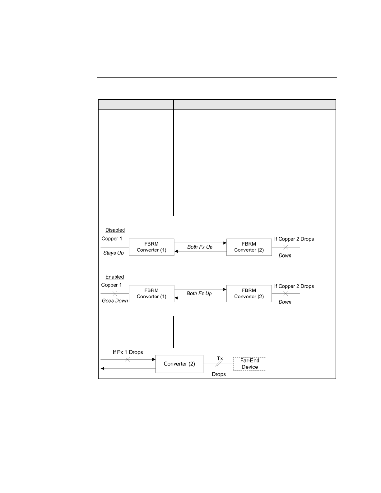
Far-End Fault (FEF)
FEF is a troubleshooting feature. With FEF enabled, if
the receiver on the fiber port goes “down” on one
Device, a FEF idle pattern is sent to the other Device to
terminate data transmission. Then an SNMP trap is sent
to the administrator, identifying the fiber link loss.
If FEF is disabled, a “down” Rx link on one Device
does not transmit to its peer, the down link notification
will not be passed on.
For FEF enabled and disabled scenarios, see illustration
below.
Far-End Fault Detection
(FEFD) Fiber Ports
If FEFD is enabled when the receiver on the fiber port
goes down on one Device, it sends a far-end-fault
pattern to the other side to bring down the fiber port on
both ends. An SNMP trap will be sent to the
administrator, indicating the fiber link loss.
If FEFD is disabled, a “down” Rx link on one Device is
not transmitted to the other Device; the link down signal
will not be passed over the link.
Continued on next page
24-Hour Technical Support: 1-800-260-1312 International: 00-1-952-941-7600
62

Transition Networks Section Vl: FBRM/BFFG Software Features
Software feature descriptions, continued
Table 3: Device Software Configurable Feature (continued)
Feature Description
Full Duplex In a full-duplex network, maximum cable lengths are
determined by the cable type. See the Cable
Specifications section for the different FBRM and BFFG
models.
The 512-Bit Rule does not apply in a full-duplex
network.
Firmware upgrades
(bootloader)
Half Duplex In a half-duplex network, the maximum cable lengths are
Auto firmware upgrade enable/disable:
In some cases, there may not be a requirement for
automatic firmware upgrades. For example, one might
connect a remote peer Device with the latest firmware
version before upgrading the local peer Device.
Typically, the local peer Device would detect a different
firmware version and will downgrade the firmware on
the remote peer Device. To prevent this, disable
automatic upgrade on the remote peer Device. The
remote peer Device will reject all upgrade requests from
the local peer Device—you can then upgrade the local
Device.
Force upgrade:
This is used to force a firmware upgrade on the remote
peer Device when the auto-upgrade feature is disabled on
the remote peer Device. This gives the local peer Device
authority to override the auto-upgrade feature of its
remote peer Device.
determined by the round trip delay limitations of each
Fast Ethernet collision domain. (A collision domain is
the longest path between any two terminal Devices, e.g.,
terminal, switch, or router.)
The 512-Bit Rule determines the maximum length of
cable permitted by calculating the round-trip delay in bit-
times (BT) of a particular collision domain. If the result
is less than or equal to 512 BT, the path is good.
For more information on the 512-Bit Rule, see the white
paper titled “Collision Domains” on Transition
Networks’ website at: www.transition.com
Continued on next page
24-Hour Technical Support: 1-800-260-1312 International: 00-1-952-941-7600 63

Section Vl: FBRM/BFFG Software Features Transition Networks
Software feature descriptions, continued
Table 3: Device Software Configurable Features (continued)
Feature Description
Operation
Administration and
Maintenance (OAM,
IEEE 802.3ah-2004
standard)
Critical Event (OAM, When the link on the other port fails, the Device sends an
IEEE 802.3ah-2004
standard)
Discovery (OAM,
IEEE 802.3ah-2004
standard)
Event Notification with
Log In (OAM,
IEEE 802.3ah-2004
standard)
Note: On the SFBRM1040-1xx redundant models, there
can be only one (1) OAM session at a time—the
OAM enabled port is user selected. Port 2 fiber is
the default port.
The Device implements the IEEE OAM 802.3ah
standard for troubleshooting and remote management.
This product implements OAM on both the fiber and
twisted pair interfaces. It implements the following
OAM features:
• Discovery
• Remote Loop Back
• Exchange of configuration information and remote
firmware upgrades with organization specific PDUs
• Link status failure indication
The Device implements the draft-ietf-hubmib-efm-mib
(EFM OAM MIB). Use the version provided on the CD.
OAM critical event signal to its peer, indicating the fault
condition.
An active-state Device initiates OAM communications
by sending PDUs across the link connected to an OAM
enabled port. The Device at the other end (if OAM
capable) responds to the request from the active Device
by establishing an OAM communications channel.
An OAM link event notifies its OAM peer of any symbol
or frame errors that occurred on its link. The window
used for error monitoring, along with the threshold value
are configurable. At the end of the window, if the errors
are greater than or equal to the threshold value, an OAM
event notification is sent to its peer. If the threshold is set
to zero, then at the end of each window an event
notification is sent—this acts more like an asynchronous
update of the link statistics.
Continued on next page
24-Hour Technical Support: 1-800-260-1312 International: 00-1-952-941-7600
64

Transition Networks Section Vl: FBRM/BFFG Software Features
Software feature descriptions, continued
Table 3: Device Software Configurable Features (continued)
Feature
Last Gasp/Dying
Gasp(OAM, IEEE
802.3ah-2004 standard)
Remote Loop Back
(OAM, IEEE 802.3ah2004 standard)
Description
All FBRM/BFFG Devices come equipped with a Last
Gasp/OAM Dying Gasp feature. This feature enables
the Device to store a small amount of power to enable
sending an SNMP trap to alert the management console
of a power failure. Feature benefits are the following:
• Notification of an impending power loss before it
happens
• Allows for quicker resolution of the power loss
The default action for last gasp/OAM dying gasp is to
send an SNMP Trap. If the desire is to send a dying
gasp through OAM, it must be configured through the
SNMP/Web interface. It requires choosing the port on
which to send the Dying Gasp command since both
ports are OAM capable. This feature helps
communicate with OAM peers that are not TN Devices.
OAM remote loop back can be used to test link health
by sending a loop back request from the active peer
Device to the remote passive peer Device. Once the
remote passive peer enters loop back mode, all frames
coming into that port are looped back, yet not forwarded
to other ports.
The OAM frames are still exchanged between the local
and remote peer Devices—only OAM frames get
through. The active peer Device discards the frames
coming out of its remote peer Device to prevent
flooding the network. See the illustration below.
Alternate Loop back
This feature can be used to verify end-to-end
connectivity.
Continued on next page
24-Hour Technical Support: 1-800-260-1312 International: 00-1-952-941-7600 65

Section Vl: FBRM/BFFG Software Features Transition Networks
Software feature descriptions, continued
Table 3: Device Software Configurable Feature (continued)
Feature
OAM Exchange of
configuration
information and remote
upgrades with
organizational specific
PDUs ( IEEE 802.3ah-
2004 standard)
Link Status Failure
Indications
Standard MIB Counters
Description
The remote peer Device (only if a TN
FBRM/BFFGDevice) set to passive mode can be
completely managed through the SNMP/Web
management by its active peer Device when set to
Active Mode. This is done using organizational specific
PDUs. When the active peer upgrades to a new revision
of firmware, it detects the firmware configuration of its
remote peer Device and upgrades it automatically.
If the active peer is in a chassis, the remote peer can be
managed through Point System management by the
management module unit (MMU).
Link status failure indication with OAM PDU flags
fielded and sent as an OAM critical event (refer to
57.4.2.1 of the standard).
The Device provides complete management through the
SNMP interface. It supports the following standard
MIBs for management using SNMPv1:
• RFC 1213 (MIB-II)
• RFC 2819 (RMON – statistics group)
• RFC 2863 (IF MIB counters)
• RFC 3635 (Ether-like MIB counters)
• RFC 1493 (Bridge MIB object counters)
• RFC 2674 (Bridge extensions counters)
Continued on next page
24-Hour Technical Support: 1-800-260-1312 International: 00-1-952-941-7600
66

Transition Networks Section Vl: FBRM/BFFG Software Features
Software feature descriptions, continued
Table 3: Device Software configurable Features (continued)
Feature
Pause (flow control) and
Back Pressure
Point System
Management
Description
Pause is used to suspend data transmission temporarily
to relieve buffer congestion. If a Device needs sometime
to clear network congestion, it will send a pause signal
to the Device at the other end, then that Device will wait
a predetermined amount of time before re-transmitting
its data.
This feature reduces data bottlenecks and allows
efficient use of network Devices, preventing data losses.
The pause feature is set in Firmware mode, using the
SNMP interface. It can be set to one of four settings:
• Disable (no pause)
• Symmetrical pause
• Asymmetric TX (transmit) pause
• Asymmetric RX (receive) pause
Note: Enable the “pause feature” if available on ALL
network Devices attached to the media
Device(s), otherwise disable this feature.
Back pressure is used in half duplex mode. Back
pressure ensures the retransmission of incoming packets
when a port using half-duplex is temporarily not able to
receive in coming frames.
The slide-in Device plugs into the chassis to provide
management through the I
2
C interface. This provides
SNMP and Web-based management through the MMU.
Continued on next page
24-Hour Technical Support: 1-800-260-1312 International: 00-1-952-941-7600 67
Section Vl: FBRM/BFFG Software Features Transition Networks
Software feature descriptions, continued
Table 3: Device Software Configurable Features (continued)
Feature
Transparent Link-Pass
Through (TLPT) and
Auto Link Restoration
Note: In the redundant
models (SFBRM1040-
1xx) this feature only
works when the Device
is in redundant mode.
Description
With OAM enabled, TLPT with automatic link
restoration is available for the copper ports on the local
and remote peer Devices. When a copper port goes
“down,” the information is passed to the other Device
and the copper port on that Device will go “down.”
When the link is restored, the link on the other port is
also restored—the fiber ports remain UP. When TLPT is
disabled, if the copper port link drops it does not affect
its peer’s copper port links.
Auto Link Restoration
will restore the broken link
automatically upon correcting the fault condition.
For TLPT disabled and enabled scenarios, see the
illustrations below.
Selective Link Pass
Through
The feature monitors the fiber Rx port for signal loss. If
the fiber Rx goes “down,” the copper port stops
transmitting. See illustration below.
24-Hour Technical Support: 1-800-260-1312 International: 00-1-952-941-7600
68

Transition Networks Section Vl: FBRM/BFFG Software Features
Software security feature descriptions
Table 4: Device Software Configurable Security Features
Security Feature
802.1x MAC filtering When enabled on a port, stops learning all MAC
CLI Timeout on Idle If the CLI session on USB/Telnet is idle for more than
IP access (system
level/port level)
MAC addresses blocking The MAC address can be added to the static MAC
Management VLAN In a VLAN enabled network, the administrator can
SNMP access The administrator can stop all SNMP access to the
Radius authentication The Device supports authentication using the RADIUS
Description
addresses. To allow any frame with a MAC address not
in the Static MAC database access, the user needs to add
the new address or it will be discarded. This allows
filtering any unauthorized access to the network by
unknown MAC addresses.
two (2) minutes, the session will time out requiring
logging in to re-gain access to the CLI.
Any management of the system via IP can be locked at
the system level, or only on certain ports. For example
management can occur via web/SNMP only on Port 1, so
that access via other ports can be blocked.
address database with the ‘connected port’ as zero. This
will cause any frames from that MAC address database
to cause an ATU-member violation on that port,
resulting in sending a trap. This could cause excessive
traps (overload the CPU with interrupts) depending on
the traffic generated by that MAC. The user can disable
all traps by setting the Ignore SA Violation on the port
that is receiving the MAC address under Advanced Port
Configuration on the web page.
assign a VLAN as a management VLAN. This VLAN
ID will be used in all management frames. This separates
the management traffic from the data.
Device, if not used. This will prevent unauthorized
access to the system configuration, but the SNMP traps
will still be sent.
protocol. When enabled, RADIUS authentication is used
for Web login, serial port, and Telnet authentication.
The Radius server and the shared secret needs to be
configured using CLI/Web/SNMP before enabling
RADIUS authentication.
Continued on next page
24-Hour Technical Support: 1-800-260-1312 International: 00-1-952-941-7600 69

Section Vl: FBRM/BFFG Software Features Transition Networks
Software security feature descriptions, continued
Table 4: Device Software Configurable Security Features (continued)
Security Feature
Select Link-Pass
Through (LTP)
Note: In the redundant
models (SFBRM1040-
1xx) this feature only
works when the Device
is in redundant mode.
USB access The USB port can be turned OFF to prevent
Username/password for
CLI
Description
When enabled, a link change on Port 2 is passed on to
Port 1 (twisted pair). For example on a 10/100BaseT-to-
100Base FX Device, when the (monitored port) fiber
goes DOWN, LPT forces the twisted pair DOWN. The
LPT Port binding allows the user to choose which port to
monitor for LPT.
unauthorized access to the system.
The username and password on the CLI (USB/Telnet) is
configurable and can be set by the administrator.
24-Hour Technical Support: 1-800-260-1312 International: 00-1-952-941-7600
70

Introduction
In this section
Transition Networks
Section VIl:
Operations
This section explains the operational status LEDs and what they indicate, along with
product features, and the three methods use to upgrade the firmware.
These are the topics:
Topic See Page
Status LEDs 72
OAM Device management configuration options 75
Firmware upgrades 76
24-Hour Technical Support: 1-800-260-1312 Intern ational: 00-1-952-941-7600 71
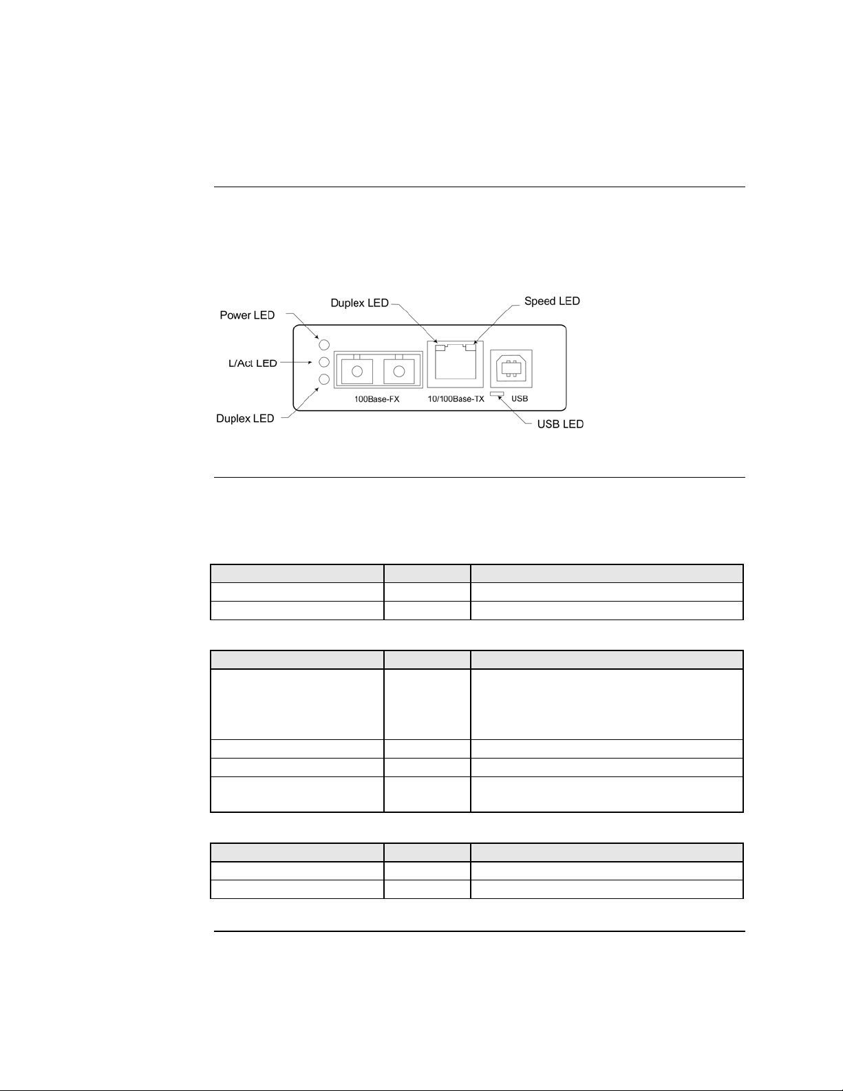
Section Vll: FBRM/BFFG Operation Transition Networks
Status LEDs
Status monitoring LEDS
The FBRM series Devices are designed to operate without user intervention. Use the
status LEDs to monitor Device operation, once it has been installed in the network.
See Figure 59.
Figure 59: FBRM Device LEDs
LED status tables
Tables 5, 6, and 7 explain the status of the power, USB, twisted pair (TP), and fiber
LEDs.
Table 5: Power and USB LEDs FBRM Devices
LEDs Color Status
Power Green ON has power/OFF no power
USB Green Blinking activity/OFF no activity
Table 6: TP Bi-Color LEDs FBRM Devices
TP LEDs Color Status
Duplex
Yellow Half duplex TPLink/activity:
ON link, BLINK activity
Green Full duplex TPLink/activity:
ON link, BLINK activity
Half Duplex/Link/Active Yellow ON Link, blinking activity
Full Duplex/Link/Active Green ON Link, blinking activity
Speed Yellow ON 10Mbs
Green ON 100Mbs
Table 7: Fiber LEDs FBRM Devices
Fiber LEDs Color Status
Link Active Green ON link, blinking activity
Duplex Green ON full, OFF half
Continued on next page
24-Hour Technical Support: 1-800-260-1312 International: 00-1-952-941-7600
72

Transition Networks Section Vll: FBRM/BFFG Operation
Status LEDs, continued
Status monitoring LEDS
The BFFG copper-to-fiber Gbit series Devices are designed to operate without user
intervention. Use the status LEDs to monitor Device operation, once it has been
installed in the network. See Figure 60.
Figure 60: BFFG Device LEDs
LED status tables
Tables 8, 9, and 10 explain the status of the power, USB, twisted pair (TP), and fiber
LEDs.
Table 8: Power and USB LEDs BFFG Devices
LEDs Color Status
Power Green ON has power/OFF no power
USB Green Blinking activity/OFF no activity
Table 9: Twisted Pair Bi-Color LEDs BFFG Devices
TP LEDs Color Status
Duplex
Yellow Half duplex TPLink/activity:
ON link, BLINK activity
Green Full duplex TPLink/activity:
ON link, BLINK activity
Half Duplex/Link/Active Yellow ON Link, blinking activity
Full Duplex/Link/Active Green ON Link, blinking activity
Speed OFF 10Mbs
Yellow ON 100Mbs
Green ON 1000 Mbs
Table 10: Fiber LEDs BFFG Devices
Fiber LEDs Color Status
Link Active Green ON link, blinking activity
Duplex Green ON full, OFF half
Continued on next page
24-Hour Technical Support: 1-800-260-1312 International: 00-1-952-941-7600 73
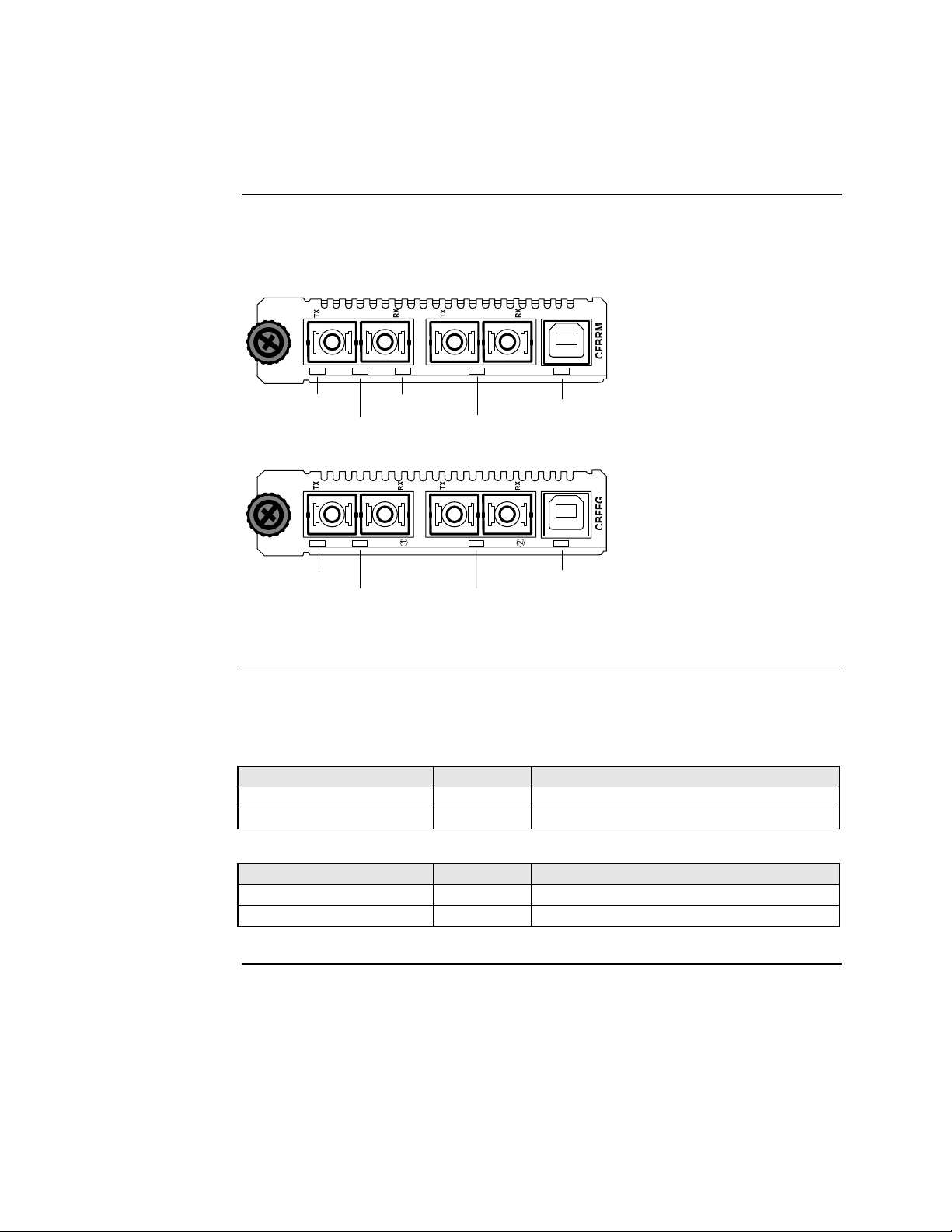
Section Vll: FBRM/BFFG Operation Transition Networks
Status LEDs, continued
Status monitoring LEDs
The FBRM Gbit and BFFG Gbit fiber series Devices are designed to operate without
user intervention. Use the status LEDs to monitor media-Device operation once
installed in the network. See Figure 61.
100Base-X 1000Base-X
USBLNKDPXPWR LNK
LED status table (Gbit)
Power
LED
Fiber Link
1000Base-X 1000Base-X
Power
LED
LED
Fiber Link
LED
Duplex
LED
Fiber Link
LED
Fiber Link
LED
USB LED
USBLNKPWR LNK
USB LED
Figure 61: CBFFG/CFBRM1xxx-xx Gbit Device LEDs
Tables 11 and 12 explain the status of the power, USB, link, duplex LEDs for Gbit
FBRM/BFFG Devices.
Table 11: Power and USB LEDs
LEDs Color Status
Power Green ON has power, OFF no power
USB Green Blinking activity, OFF no activity
Table 12: Fiber LEDs
Fiber-LEDs Color Status
Link Green ON link; blinking activity
ON full; OFF half (BFFG models only) Duplex Green
24-Hour Technical Support: 1-800-260-1312 International: 00-1-952-941-7600
74

Transition Networks Section Vll: FBRM/BFFG Operation
OAM Device management configuration options
OAM mgmt. configuration options
OAM Mode control is a feature of the FBRM/BFFG Devices. It can be set to ‘Auto’
(default) or set manually (Active/Passive/Disabled):
• In ‘Auto’ Mode, the Device decides the OAM operation
• In Manual Mode, the user decides the OAM Mode (Active/Passive/Disabled)
Table 13 lists the default configuration.
Table 13: OAM Device Configurations
Chassis Device Standalone OAM Capability
Active Passive The active Device manages the passive Device.
Active Active The Devices exchange status information through
OAM, but cannot be managed through OAM.
Passive Active The chassis Device needs to be in Active Mode since
it is being managed by the point system agent.
Management through ‘OAM and the chassis
simultaneously will cause configuration errors.
Note: A chassis Device in a single slot chassis without the Point System agent
functions as a standalone Device.
24-Hour Technical Support: 1-800-260-1312 International: 00-1-952-941-7600 75

Section Vll: FBRM/BFFG Operation Transition Networks
Firmware upgrades
Introduction
The firmware image on the Device can be upgraded by these methods:
• TFTP protocol
• XModem
• OAM
When enabled, OAM is done automatically when the active peer detects that its
remotely managed peer is running a different version of the firmware. TFTP and
XModem are initiated by the user. All firmware upgrades are done by the
“bootloader.”
Note: The bootloader recognizes incompatible FBRM/BFFG BIN files when
upgrading. Since there are different FBRM/BFFG Device types, it is possible
that the user could download the wrong BIN file; when it receives an
incorrect file through TFTP or XMODEM, the following message will
appear on the screen:
Bootloader: Hardware and BIN file mismatch, upgrade
aborted.
XModem method
To upgrade the firmware via XModem, do the following:
Step Action
1.
At the console prompt> type xmodemupgrade
2.
Press the ENTER key and a decision prompt will appear as shown in
Figure 62.
Console:/>xmodemupgrade
Do you wish to proceed to upgrading (y/n):_
Figure 62: Decision Prompt for Firmware Upgrades
Note: If you select “Y,” the firmware image on the targeted Device will be erased.
Continued on next page
24-Hour Technical Support: 1-800-260-1312 International: 00-1-952-941-7600
76

Transition Networks Section Vll: FBRM/BFFG Operation
Firmware upgrades, continued
XModem method (continued)
Step Action
3. Type “Y” at the prompt.
4. Press the ENTER key to launch the firmware upgrade screen, shown in
Figure 63.
10/100BaseT to 100BaseFX IPBased 802.3ah Bridge
Version A
Copyright (c) 2006 Transition Networks
Reading config from flash........done
Erasing Application Memory
Start sending file through XModem...
Transfer completed
Checking CRC. . . . . . . .
Figure 63: Firmware Upgrade via Xmodem
5. Choose the ‘send file’ option from Hyperterminal with ‘XModem’ as the
protocol. After the download, the bootloader verifies the CRC of the file
and resets itself to start the user application.
Continued on next page
24-Hour Technical Support: 1-800-260-1312 International: 00-1-952-941-7600 77

Section Vll: FBRM/BFFG Operation Transition Networks
Firmware upgrades, continued
TFTP method
The Device can be upgraded remotely using TFTP. A valid IP address, subnet,
gateway, TFTP server IP address, and filename must be configured before starting
the upgrade process.
TFTP can be started in the following ways:
• ‘tftpupgrade’ command at the CLI
• On the web using Æ “Local System Configuration” Æ ‘TFTP upgrade’
[perform(1)]
• Using SNMP, set ‘sfbrm100SysTFTPCmd’ to ‘1’ (perform)
After initiating the command, the system resets to start the bootloader, and then the
tftp upgrade will start. A message will appear like the example shown Figure 64.
10/100BaseT to 100BaseFX IPBased 802.3ah Bridge
Version A
Copyright (c) 2006 Transition Networks
Reading config from flash........done
Erasing Application Memory
Set to TFTP Boot from Server nnn.nnn.nnn.nnn
Getting File : FBRM.bin . . . . . . . . . . . done
Checking CRC. . . . . . . .
Figure 64: Firmware Upgrade via TFTP
After a successful upgrade, the application will start up.
Continued on next page
24-Hour Technical Support: 1-800-260-1312 International: 00-1-952-941-7600
78

Transition Networks Section Vll: FBRM/BFFG Operation
Firmware upgrades, continued
OAM method
What happens when the upgrade fails?
OAM firmware upgrades are done by the local active peer Device to its remote
passive peer Device automatically. This occurs when the active peer Device finds that
its remote peer has a firmware revision different from its own. The active peer Device
sends a bootloader command to its remote peer. When the firmware upgrade on the
remote peer Device is completed, it will perform a “reset” to activate the new
firmware—no user intervention is required. (Active and passive peer relationships are
established during configuration.)
The FBRM/BFFG Devices can have a corrupted image for a variety of reasons. If the
image is corrupt, the following will occur: The bootloader checks the CRC to make
sure the image is good; if the check fails, it will re-initiate each method (XMODEM,
TFTP, OAM) in an attempt to accomplish the upgrade. The sequences is a follows:
Stage Description
A. XMODEM will re-initiate if there is no input from the console; it will try
the OAM method.
B.
OAM initiates to locate an active peer on the network to get the upgrade
image; if an active peer is not available, it will try the TFTP method.
C.
TFTP initiates a request to the TFTP server to get the upgrade image for
the Device.
D.
This process continuously loops through these upgrade methods until one
of the methods successfully upgrades the firmware image.
Admin intervention
To do a firmware upgrade from the console, before the bootloader moves to the next
method, it waits for ‘2’ seconds for user input displaying the following message:
“Moving to XMODEM upgrade, Hit 'ESC’ to skip or ctrl-C
for CLI.”
Bootloader CLI
The “bootloader” has a CLI to configure network setting, such as the TFTP server
address, filename, and the boot method to use for upgrading the firmware.
The CLI can be started by pressing any key within ‘2’ seconds before it starts the
CRC validation, or by pressing the CTRL-C keys when it shows the following
message:
Transfer Failed
Moving to OAM, XMODEM or TFTP upgrade, Hit 'ESC' to skip/
<ctrl-c> for CLI.
Continued on next page
24-Hour Technical Support: 1-800-260-1312 International: 00-1-952-941-7600 79

Section Vll: FBRM/BFFG Operation Transition Networks
Firmware upgrades, continued
Accessing the bootloader CLI
To access the bootloader CLI to upgrade the firmware, do the following:
Step Action
1.
When “Transfer Failed” appears on the screen, within ‘2’
seconds, press the CTRL-C keys to bring up the bootloader CLI, as
shown in Figure 65.
10/100BaseT to 100BaseFX IP-Based 802.3ah Bridge
Version A [Mar 2 2006 09:56:02]
Copyright (c) 2006 Transition Networks
Reading config from flash........done.
BOOT LOADER CLI
Type 'h' for help
BOOT:>
Figure 65: Bootloader CLI
2.
At the BOOT:> prompt type the letter “h” to bring up the help screen,
shown in Figure 66.
h Display this help
p Ping a host
z Clear entire Application flash
x Set boot method as xmodem
t Set boot method as tftp
o Set boot method as OAM
s Show system information
n configure network information
r reset system
q Exit Boot CLI
BOOT:>
Figure 66: Bootloader Help Screen
Note: When y ou press the LETTER key of any command it might not appear at
the BOOT:> prompt, but the result will appear on the screen.
Continued on next page
24-Hour Technical Support: 1-800-260-1312 International: 00-1-952-941-7600
80

Transition Networks Section Vll: FBRM/BFFG Operation
Firmware upgrades, continued
Accessing the bootloader CLI (continued)
Step Action
At the BOOT:> prompt type the letter “t” to establish TFTP as the reboot
3.
method.
At the BOOT:> prompt type the letter “s” to view system information, as
4.
shown in Figure 67.
System configuration:
IP Address : 192.251.144.150
Subnet Mask : 255.255.255.0
Default Gateway : 192.251.144.2
MAC Address : 00:c0:f2:00:d1:bc
TFTP Server address : 0.0.0.0
TFTP Filename :
BOOT:>
Figure 67: System Configuration Information
5. If system configuration parameters are entered incorrectly or missing as
shown above, at the BOOT:> prompt type the letter “n.”
6. Press the EN TER key until the desired parameter appears on the screen
(TFTP Filename []). See Figure 68.
BOOT:>
Enter the Network configuration IP Address [192.251.144.150]:
Subnet Mask [255.255.255.0]:
Gateway [192.251.144.2]:
TFTP Server IP [0.0.0.0]:
TFTP Filename []:
Figure 68: Network Configuration Screen
7. Enter the necessary data.
8. When done, press the letter “r” key to reboot the Device. The firmware
image will be burned to flash memory of the Device. When completed,
the Device will reboot and return to the Login> prompt.
24-Hour Technical Support: 1-800-260-1312 International: 00-1-952-941-7600 81

Transition Networks
Section Vlll:
Troubleshooting
Introduction
In this section
This section provides basic troubleshooting information for the FBRM/BFFG Device
via a problem and corrective action table. The problems are stated in the problem
column and the action(s) to take for the problem is stated in the corrective action
column. If the corrective measures listed do not correct the problem, contact our 24Hour Technical Support department at 1-800-260-1312, International: 00-1-952-941-
7600.
These are the topics:
Topic See Page
Troubleshooting problem and corrective action table 83
24-Hour Technical Support: 1-800-260-1312 Intern ational: 00-1-952-941-7600 82

Section Vlll: FBRM/BFFG Troubleshooting Transition Networks
Troubleshooting problem and corrective action table
Problem Corrective Action
Device does not power
up
Cannot detect or
communicate with the
xFBRM/xBFFG
Cannot access the Device
via USB port
The local Device LACT
LED is ON but no data
transfer is detected (LED
flashing)
Ports do not link up
• Is the Device power LED ON?
• Is the power adapter’s barrel inserted fully into the Device?
• Is the power adapter plugged into an AC outlet?
• Is the AC outlet active; if not, check the outlet’s circuit breaker?
• Contact Technical Support. US/Canada: 1-800-260-1312, International:
00-1-952-941-7600.
• If CFBRM/CBFFG is in a cascaded chassis move the CFBRM/CBFFG
to the master chassis
• Upgrade to the latest version of firmware
• Contact Technical Support. US/Canada: 1-800-260-1312, International:
00-1-952-941-7600.
• Is the USB driver installed?
• Is the serial access disabled?
• Is the USB cable connected to the Device and to the host computer?
• Is the terminal emulator software configured properly for the USB port
and launched? See Driver Installation and COM Port Setup: Terminal
Emulator section.
• Contact Technical Support. US/Canada: 1-800-260-1312, International:
00-1-952-941-7600.
• Is the input source to the local Device active?
• Is the RJ-45 network cable fully inserted into the local Device, also into
the network Device?
• Is the fiber cable properly inserted into the local Device and the end
source Device?
• Contact Technical Support. US/Canada: 1-800-260-1312, International:
00-1-952-941-7600.
• Check the cable type needed for the Device and make sure the right
cable is used.
• Check Auto-Negotiation setting.
• Check if TPLT or remote fault-detect condition was triggered.
• Contact Technical Support. US/Canada: 1-800-260-1312, International:
00-1-952-941-7600.
Continued on next page
24-Hour Technical Support: 1-800-260-1312 International: 00-1-952-941-7600 83

Transition Networks Section Vlll: FBRM/BFFG Troubleshooting
Troubleshooting problem and corrective action table, continued
Problem Corrective Action
The Trap Server does not
record traps
• Ensure the Trap Server application is running.
o In the Windows environment, if the “TN” icon is displayed in the
lower right corner of the monitor, then the Trap Server is running.
• SNMP traps may be blocked by a router or firewall. Consult your
Network administrator to determine if this is the case.
• The SNMP trap manager may not be configured properly. The result is
that the SNMP agent does not know the proper IP address. Use the “set”
command to configure the trap manager. Enter the following command
on a single line:
CPSMM100> set=cpsmm100SNMPTrapMgr.<cabinet serial number>.<slot number of the
MM>,ip,<new IP Address of NMS>
• Alternatively, use the “getnext” command to “get” much of this
information and then use the “set=*” command to issue the set request.
The following is an example. Enter “Super-User Mode”:
CPSMM100> su=<private community name>
[su] CPSMM>
Enter the “getnext” command:
[su] CPSMM100> getnext=cpsmm100snmptrapmgr
The response is:
SNMP: GETNEXT [192.251.144.229] id=D2EE6F3F ind=0 cpsmm100snmptrapmgr.1758208.1
1P Address [4/0x4] 192.251.144.235
Enter the set request:
[su] CPSMM100> set=*,ip,172.16.45.105
The response is:
SNMP: SET [192.251.144.229] id=D2EE6F3F ind=0 cpsmm100SNMPTrapMgr.1758208.1
IP Address [4/0x4] 172.16.45.105
Save the changes:
[su] CPSMM100> save
Continued on next page
24-Hour Technical Support: 1-800-260-1312 International: 00-1-952-941-7600
84

Section Vlll: FBRM/BFFG Troubleshooting Transition Networks
Troubleshooting problem and corrective action table, continued
Problem Corrective Action
The Trap Server does not
record traps,(continued)
Cannot activate IP-based
management
TLPT and SLDP are not
working
OAM session is not
active
OAM remote Device is
detected on local, but
cannot configure remote
from local
The response is:
FLASH: Saving configuration, please wait up to one minute...
Writing Flash
(04004500,05E8,00FE0000,00FFFFFE)
Erasing
.
Done Erasing/Verifying
Writing [000005E8]
#[0000FFFF]
Done Writing
Verifying
FLASH: Write complete.
• Are the IP, Gateway, and subnet mask configured correctly?
• With DHCP enabled, DHCP could have failed leaving the system with
the old static IP config. Verify the configuration via the USB port.
• Make sure IP-based access is not turned OFF in the system.
• Contact Technical Support. US/Canada: 1-800-260-1312, International:
00-1-952-941-7600.
• Are the TLPT and SLDP enabled on both systems? Refresh web pages
to make sure they are set.
• Check if port binding for TLPT/RFD is set to the active OAM channel.
• With 100Base-Fx, make sure “far end fault” is enabled.
• Contact Technical Support. US/Canada: 1-800-260-1312, International:
00-1-952-941-7600.
• If OAM is enabled, check the ports on the local and remote Devices.
• Make sure the local Device is in OAM “Active” Mode.
• Make sure the remote peer Device is set to “Passive” Mode.
Note: OAM session can be formed between Devices with both set to
Active Mode, but this prevents remote management. The remote
Device should be in “Passive” Mode for management.
• Contact Technical Support. US/Canada: 1-800-260-1312, International:
00-1-952-941-7600.
Continued on next page
24-Hour Technical Support: 1-800-260-1312 International: 00-1-952-941-7600 85

Transition Networks Section Vlll: FBRM/BFFG Troubleshooting
Troubleshooting problem and corrective action table, continued
Problem Corrective Action
Unable to do
configuration directly
using IP based
management on Remote
Device
Chassis FBRM/BFFG
not recognized by the
chassis agent
Chassis FBRM/BFFG is
in a single-slot chassis,
but the Port 2 comes up
in OAM “Passive” Mode
with OAM Mode control
is set to ‘auto’
• If the OAM session is active, the active local peer Device sends
configuration information; if the user attempts to go directly to the
remote passive peer Device, the configuration will be overwritten by the
OAM update from the local active peer. It is advisable to always use the
local active peer Device to manage its remote passive peer Device.
• Contact Technical Support. US/Canada: 1-800-260-1312, International:
00-1-952-941-7600.
• Make sure the Point System agent has the latest firmware version for the
CFBRM/CBFFG Device. Use the FEATSUPP command to see if the
Devices are supported.
• Contact Technical Support. US/Canada: 1-800-260-1312, International:
00-1-952-941-7600.
• The chassis Devices in single-slot chassis function as a standalone
Device.
• Chassis Device needs a Point System management module in a chassis
to switch to “Active” Mode, or to set OAM Mode manually.
• Contact Technical Support. US/Canada: 1-800-260-1312, International:
00-1-952-941-7600.
24-Hour Technical Support: 1-800-260-1312 International: 00-1-952-941-7600
86

Section Vlll: FBRM/BFFG Troubleshooting Transition Networks
Intentionally Blank
24-Hour Technical Support: 1-800-260-1312 International: 00-1-952-941-7600 87

Transition Networks
Section lX:
Copper Cable & Fiber Optic Specifications
Introduction
In this section
This section provides copper and fiber cable specifications.
These are the topics:
Topic See Page
Copper cables 89
Fiber optic cables and connectors 90
24-Hour Technical Support: 1-800-260-1312 Intern ational: 00-1-952-941-7600 88

Section lX: FBRM/BFFG Cable & Fiber Optic Specifications Transition Networks
Copper cables
Characteristics
Copper cable specification
Cooper cable physical characteristics must meet or exceed IEEE 802.3™
specifications.
Category 5: minimum
Gauge: 24 to 22 AWG
Attenuation: 22.0 dB/100m @ 100 MHz
Maximum cable distance: 100 meter (328 ft.)
• Straight-through or crossover twisted-pair cable may be used. See Figure 69.
• Shielded twisted-pair (STP) or unshielded twisted-pair (UTP) may be used.
• Pins 1&2 and 3&6 are the two active pairs in an Ethernet network.
• RJ-45 pin-outs on MDI cable: Pin 1 = TD+, Pin 2 = TD-, Pin 3 = RD+, Pin 6 =
RD-
• Use only dedicated wire pairs for the active pins.
(e.g., blue/white & white/blue, orange/white & white/orange, etc.)
• DO NOT use flat or silver satin wire.
Figure 69: MDI Straight Through and MDI-X Crossover Cables
24-Hour Technical Support: 1-800-260-1312 International: 00-1-952-941-7600 89

Transition Networks Section lX: FBRM/BFFG Cable & Fiber Optic Specifications
Fiber optic cable and connector specifications
Fiber cable characteristics
Copper-to-fiber connectors
Cable physical characteristics must meet or exceed IEEE 802.3™ specifications.
Parameter Specification
Bit Error Rate: <10-9
Single mode fiber: 9 µm
Multimode fiber: 62.5/125 µm
Multimode fiber: 100/140, 85/140, 50/125 µm
The following are FBRM10xx-1xx copper-to-fiber connector specifications.
Fiber Optics Specifications
CFBRM1011-100
SFBRM1011-100
Fiber-optic transmitter power:
Fiber-optic receiver sensitivity:
Link budget:
CFBRM1013-100
SFBRM1013-100
Fiber-optic transmitter power:
Fiber-optic receiver sensitivity:
Link budget:
CFBRM1014-100
SFBRM1014-100
Fiber-optic transmitter power:
Fiber-optic receiver sensitivity:
Link budget:
1300 nm multimode
min: -19.0 dBm max: -14.0 dBm
min: -30.0 dBm max: -14.0 dBm
11 dB
1300 nm multimode
min: -19.0 dBm max: -14.0 dBm
min: -30.0 dBm max: -14.0 dBm
11 dB
1310 nm single mode
min: -15.0 dBm max: -8.0 dBm
min: -31.0 dBm max: -8.0 dBm
16 dB
CFBRM1015-100 (long haul)
SFBRM1015-100 (long haul) 1310 nm single mode
Fiber-optic transmitter power: min: -8.0 dBm max: -2.0 dBm
Fiber-optic receiver sensitivity: min: -34.0 dBm max: -7.0 dBm
Link budget: 26 dB
WARNING: Visible and invisible laser radiation when open. Do not stare into the
beam or view the beam directly with optical instruments. Failure to observe this
warning could result in an eye injury or blindness.
WARNING: Use of controls, adjustments or the performance of procedures other
than those specified herein may result in hazardous radiation exposure.
Continued on next page
24-Hour Technical Support: 1-800-260-1312 International: 00-1-952-941-7600
90

Section lX: FBRM/BFFG Cable & Fiber Optic Specifications Transition Networks
Fiber optic cable and connector specifications, continued
Copper-to-fiber connectors (continued)
Fiber Optics Specifications
CFBRM1016-100 (extra long haul)
SFBRM1016-100 (extra long haul) 1310 nm single mode
Fiber-optic transmitter power: min: -5.0 dBm max: 0.0 dBm
Fiber-optic receiver sensitivity: min: -34.0 dBm max: -7.0 dBm
Link budget: 29 dB
CFBRM1017-100 (long wave length)
SFBRM1017-100 (long wave length)
Fiber-optic transmitter power:
Fiber-optic receiver sensitivity:
Link budget:
CFBRM1035-100
SFBRM1035-100
Fiber-optic transmitter power:
Fiber-optic receiver sensitivity:
Link budget:
CFBRM1029-100
CFBRM1029-101
SFBRM1029-100
SFBRM1029-101
Fiber-optic transmitter power:
Fiber-optic receiver sensitivity:
Link budget:
CFBRM1029-102
CFBRM1029-103
SFBRM1029-102
SFBRM1029-103
Fiber-optic transmitter power:
Fiber-optic receiver sensitivity:
Link budget:
Note: The fiber optic transmitters on these Devices meet Class I Laser safety
requirements per IEC-825/CDRH standards and comply with 21
CFR1040.10 and 21CFR1040.11.
WARNING: Visible and invisible laser radiation when open. Do not stare into the
beam or view the beam directly with optical instruments. Failure to observe this
warning could result in an eye injury or blindness.
WARNING: Use of controls, adjustments or the performance of procedures other
than those specified herein may result in hazardous radiation exposure.
1550 nm single mode
min: -5.0 dBm max: 0.0 dBm
min: -34.0 dBm max: -7.0 dBm
29 dB
1550 nm single mode
min: -0.0 dBm max: 5.0 dBm
min: -36.0 dBm max: -3.0 dBm
36 dB
1310 nm (TX)/1550 nm (RX) simplex
1550 nm (TX)/1310 nm (RX) simplex
1310 nm (TX)/1550 nm (RX) simplex
1550 nm (TX)/1310 nm (RX) simplex
min: -14.0 dBm max: -8.0 dBm
min: -33.0 dBm max: -3.0 dBm
19 dB
1310 nm (TX)/1550 nm (RX) simplex
1550 nm (TX)/1310 nm (RX) simplex
1310 nm (TX)/1550 nm (RX) simplex
1550 nm (TX)/1310 nm (RX) simplex
min: -8.0 dBm max: -3.0 dBm
min: -33.0 dBm max: -3.0 dBm
25 dB
Continued on next page
24-Hour Technical Support: 1-800-260-1312 International: 00-1-952-941-7600 91

Transition Networks Section lX: FBRM/BFFG Cable & Fiber Optic Specifications
Fiber optic cable and connector specifications, continued
Copper-to-Copper-to-fiber connectors with DMI
Fiber Optics Specifications
CFBRM1011-110 DMI
SFBRM1011-110 DMI 1300 nm multimode
Fiber-optic transmitter power: min: -19.0 dBm max: -14.0 dBm
Fiber-optic receiver sensitivity: min: -30.0 dBm max: -14.0 dBm
Link budget: 11 dB
CFBRM1013-110 DMI
SFBRM1013-110 DMI
Fiber-optic transmitter power:
Fiber-optic receiver sensitivity:
Link budget:
CFBRM1014-110 DMI
SFBRM1014-110 DMI
Fiber-optic transmitter power:
Fiber-optic receiver sensitivity:
Link budget:
CFBRM1015-110 DMI (long haul)
SFBRM1015-110 DMI(long haul)
Fiber-optic transmitter power:
Fiber-optic receiver sensitivity:
Link budget:
CFBRM1016-110 DMI
SFBRM1016-110 DMI
(extra long haul)
Fiber-optic transmitter power:
Fiber-optic receiver sensitivity:
Link budget:
CFBRM1017-110 DMI
SFBRM1017-110 DMI
(long wave length)
Fiber-optic transmitter power:
Fiber-optic receiver sensitivity:
Link budget:
CFBRM1035-110 DMI
SFBRM1035-110 DMI
Fiber-optic transmitter power:
Fiber-optic receiver sensitivity:
Link budget:
1300 nm multimode
min: -19.0 dBm max: -14.0 dBm
min: -30.0 dBm max: -14.0 dBm
11 dB
1310 nm single mode
min: -15.0 dBm max: -8.0 dBm
min: -31.0 dBm max: -8.0 dBm
16 dB
1310 nm single mode
min: -8.0 dBm max: -2.0 dBm
min: -34.0 dBm max: -7.0 dBm
26 dB
1310 nm single mode
min: -5.0 dBm max: 0.0 dBm
min: -34.0 dBm max: -7.0 dBm
29 dB
1550 nm single mode
min: -5.0 dBm max: 0.0 dBm
min: -34.0 dBm max: -7.0 dBm
29 dB
1550 nm single mode
min: -0.0 dBm max: 5.0 dBm
min: -36.0 dBm max: -3.0 dBm
36 dB
Continued on next page
24-Hour Technical Support: 1-800-260-1312 International: 00-1-952-941-7600
92
 Loading...