

Page 1
50 Hz P ackage
Heat Pump Units
Product Data
Convertible Models
WCC030,040,050
30, 40, 50 MBh
IPB-99-7-EN-10-6-99
Page 2
General
Features
T-Top™
Corrosion Resistant Screws
Powder Paint
Water-Shed™ Base
High Efficiency
Climatuff
DuraT uff™ Plate Fin Coil
Time Defrost Control
Sloped Drain Pan
100% Foil Faced Insulation
Easy Access
©American Standard Inc. 1999 IPB-99-7-EN-10-6-99
®
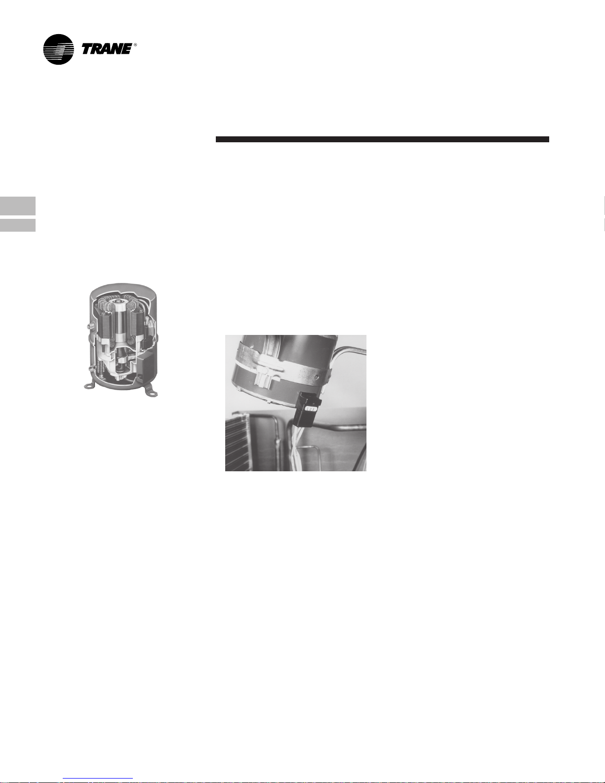
Compressor
Page 3

Contents
Feature Summary 2
Features and Benefits 4
Standard Equipment 4
Impack Accessories 5
Optional Equipment 6
Selection Procedure 7
Model Number Nomenclature 7
General Data 8
English Units
WCC030FD00B 8
WCC040FD00B 8
WCC050FD00B 8
Metric Units
WCC030FD00B 9
WCC040FD00B 9
WCC050FD00B 9
IPB-99-7-EN-10-6-99 3
Perf ormance Data 10
Cooling English Units 10
Cooling Metric Units 11
Heating English Units 12
Heating Metric Units 13
Indoor Blower Performance 14
Optional Equipment 15
Controls 16
Field Wiring 17
Dimensions 20
Mechanical Specification Options 26
Page 4
• High Efficiency
Impack performance is among the highest
in the industry.
• Climatuff® Compressor
Protection against chemical, electrical, and
mechanical stresses are built in for
efficiency and a longer life. The compressor
is backed by a 5-year limited warranty, with
an optional warranty for 5 more years.
• Time Defrost Control
This is an electronic, time initiated, temperature terminated defrost system that offers a
choice of 50, 70, or 90 minute cycles. The
time override limits the defrost cycle to 10
minutes.
• Convertibility
Impack units are easily converted from
horizontal to downflow with the removal of
one screw from each panel. Accordingly, the
need to stock both dedicated horizontal and
dedicated downflow models has been
eliminated.
• Installation
The ease of installation and application
flexibility exhibited through the design
reduce both field time and material.
• Application
The low profile horizontal duct take-offs
eliminate the need for expensive transition
ducts in crawl space applications.
• Commonality
The common cabinet among the TCC’s,
WCC’s, and YCC’s minimizes both the
training of sales and service personnel and
replacement parts inventory.
• Flexibility
A single curb fits the entire Impack line from
1.5 tons through 5 tons thereby providing
great installation flexibility on shopping
malls, factories, schools, and other
commercial buildings where a mix-match of
tonnages and utilities is desired.
Features and
Benefits
Standard Equipment
• Water-Shed™ Base
Superior water integrity is accomplished
with the Water-Shed™ base pan having
elevated downflow openings and a perimeter channel that prevents water from
draining into the ductwork.
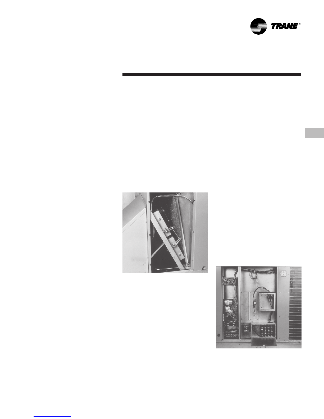
• Easy Access
All electrical components can be diagnosed
and replaced with the removal of one panel
that is attached with two screws.
• Service
All wiring is both numbered and color coded
thereby reducing training and servicing
costs related to circuit tracing and components replacements.
• Maintenance
A plug on the outdoor fan motor allows the
top cover to be removed completely without
the hassle of cumbersome wires. The
unique service orifice ring allows the indoor
fan motor/blower to be removed as a unit.
• Plate Fin Coil
Refrigeration coils are built with internally
enhanced copper tubing for high efficiency
with less coil area.
• Shipping
Unit dimensions were carefully selected to
provide an attractive aspect ratio and for
shipping and handling considerations.
• Good Neighbor
Most units can be installed flush with the
residence or building thereby minimizing the
ground space required. Blankets of
insulation reduce blower noise and energy
losses to the outside environments.
• Rooftop Mounting
The cabinets are physically smaller than
most competitive models. This means less
intrusive installations on residential rooftops
where aesthetics are critical.
• Handling
The three-way wooden skid allows for easy
loading between the wheel wells on pickup
trucks for transporting to job sites.
• Structure
The units are lighter weight through the use
of high technology components thereby
reducing mounting structure requirements
and difficulty when handling.
• Duct Flanges
Only Impack has downflow duct flanges for
duct attachments that preserve the built-in
water integrity.
• Corrosion
The drain pan is engineered material and
eliminates the need for coatings and sealers
to prevent sweating and corrosion. The
heavy gauge, zinc-coated steel cabinet has
a weather resistant enamel finish that stays
attractive and protects your investment for
years.
• Low Ambient Control
Zero degree ambient cooling is accomplished with two kits. One for low cost
installations when full tonnage is not
needed. The other kit maintains head
pressure and full capacity at zero degrees.
• Quality and Reliability Testing
We perform a 100% coil leak test at the
factory. The evaporator and condenser
coils are leak tested at the factory. The
evaporator and condenser coils are leak
tested at 200 psig and pressure tested to
450 psig respectively. In addition the Impack
designs were rigorously rain
tested at the factory to ensure water
integrity. Shipping tests are performed to
determine packaging requirements. Factory
shake and drop tests are used as part of
the package design process to help assure
that the unit will arrive at the job site in top
condition. Additionally, all components are
inspected at the point of final assembly.
Substandard parts and components are
identified and rejected immediately. Every
unit receives a 100% run test before leaving
the production line to make sure it lives up
to rigorous Trane® requirements. We at
Trane test our designs at our factory and not
on our customers!
4 IPB-99-7-EN-10-6-99
Page 5
Impack
Accessories
• Standard Thermostats
No special thermostats are needed with
Impack units.
• Filter Frame Kit
The Impack filter frames accept standard
filters and fit inside the unit. The frame kits
function in either horizontal or downflow
duct configurations.
• Coil Guard Kit
The guards are vinyl coated 1" x 3" wire
grills. These grills will protect the coil from
hail, kids with sticks as well as normal
shipping and installation handling damage.
• UNI-CURB™
One universal curb fits all the Impack
models. It ships knocked down. The curb
design incorporates the popular locking tabs
for quick and easy assembly. Full perimeter
curbs are also available for all models.
• 25% Fresh Air Kit
The kit installs over the horizontal return air
opening with six screws for downflow requirements. It can be used on horizontal air flow
applications by cutting a hole in the return
air duct or in the unit filter access panel.
• Rectangular to Round Duct Kits
The adapter kit can be used in either
horizontal or downflow applications.
• Low Ambient Kit
An EDC provides low ambient cooling to 0° F
with some reduced capacity and protects
the system against evaporator icing during
other unusual cooling conditions.
• Fan Delay Relay Kit
This solid state kit is a time delay that keeps
the indoor blower on for about ninety
seconds and increases the SEER. It wires
into the low voltage unit pigtails.
• High Static Motor Kit
Contains a higher torque indoor fan motor.
• Lifting Lug Kit
Four reusable lugs in each kit allow units to
be easily lifted to rooftop installations. These
lugs snap (no screws required) into slots in
the unit drip lip channel.
• Start Kit
The kit mounts in the control box for those
installations with specific conditions such as
excessive voltage drop due to long wires.
(This is a capacitor and start relay kit and is
not a PTC device.) This kit can be a good
specification buster!
IPB-99-7-EN-10-6-99 5
• Economizer
The economizer fits inside the unit with only
the rain hood and barometric relief on the
outside. Cabling (with polarized plugs) is
shipped with the economizer. This cabling is
easily routed to the control box where it
terminates in low voltage pigtails. The
economizer features a fully modulating low
voltage motor eliminating the need for any
high voltage wiring. The economizer must
be used with the filter frame kit . . . no return
air filter in the economizer kit. A dr y bulb
sensor is shipped with the economizer. The
economizer was not designed for use in
horizontal applications. Heat pump applications require a relay kit.
• Enthalpy Control Kit
For those applications specifying an economizer with enthalpy control, this control can
be used in place of the dry bulb sensor or,
alternately, two enthalpy controls can be
paired to provide differential enthalpy control.
• Single Power Entry Kit
The kit minimizes installation costs by
reducing the load center circuit requirement
and reducing the number of circuit pulls
needed.
Page 6

Optional
Equipment
OPTIONAL EQUIPMENT FOR PACKAGE UNITS (Check mark [
Indoor Thermostats — 3H/2C Auto Changeover ............................................................................................................................... BAY28X153A [ ]
Roof Curb (Flat Roof) (WCC-F) 5 ................................................................................................................................................. BAYCURB030A [ ]
Roof Curb (Flat Roof) (WCC040-050F) ........................................................................................................................................ BAYCURB034A [ ]
0-25% Manual Fresh Air Damper (WCC030F) 2 ........................................................................................................................BAYDMPR040A [ ]
0-25% Manual Fresh Air Damper (WCC040,050F) 2 ................................................................................................................. BAYDMPR041A [ ]
12" Round Duct Adapter (2 per box) (WCC030F) ........................................................................................................................ BAYDUCT004A [ ]
14" Round Duct Adapter (1 per box) (WCC040,050F) ................................................................................................................. BAYDUCT005A [ ]
0-100% Mod. Economizer w/Baro. Relief (WCC030F) 12345 .............................................................................................. BAYECON054A [ ]
0-100% Mod. Economizer w/Baro. Relief (WCC040,050F) 12345 ....................................................................................... BAYECON055A [ ]
0-100% Horizontal Economizer 23 ............................................................................................................................................ BAYECON073A [ ]
Enthalpy Control (solid state) (WCC-F) 3 .....................................................................................................................................BAYENTH001A [ ]
Economizer Relay Kit (WCC-F) 1 .................................................................................................................................................BAYRLAY003A [ ]
Filter Frame (20x25x1" filter not incl.) WCC030F 2 .......................................................................................................................BAYFLTR012A [ ]
Filter Frame (3-10x25x1" filters not incl.) WCC040,050F 2 ..........................................................................................................BAYFLTR014A [ ]
Lifting Lug Kit (WCC-F) ........................................................................................................ ............................................................. BAYLlFT002A [ ]
Evaporator Defrost Control (Low Ambient Cool) Kit (WCC-F) 1 ................................................................................................. BAYLOAM011A [ ]
Condenser Coil Guard (WCC030F) .............................................................................................................................................. BAYGARD017A [ ]
Condenser Coil Guard (WCC040,050F) ....................................................................................................................................... BAYGARD022A [ ]
High Static Motor (WCC030F) (230/460) (3/4 hp) ........................................................................................................................ BAYHSMT043A [ ]
High Static Motor (WCC040,050F) (230/460) (1 hp) .................................................................................................................... BAYHSMT044A [ ]
Anti-Short Cycle Timer (WCC-F) ...................................................................................................................................................... BAYASCT001 [ ]
Indoor Fan Delay Kit (WCC-F) ............................................................................................................................................................ BAY24X045 [ ]
Notes:
1
Relay required with economizer on WCC-F models .
2
Must use filter frame when economizer/fresh air kit is used.
3
Dry bulb control standard with economizer.
2H/1C Auto ................................................................................................................................................... BAY28X138A [ ]
Prog. Setback Thermostat (WCC-F) ........................................................................................................... BAYSTAT024B [ ]
2 Stage Htg/Clg Thermostat (WCC-F) .......................................................................................................... BAYSTAT239 [ ]
Remote Sensor for Prog. Thermostat............................................................................................................ BAYSTAT021 [ ]
Fan Control Relay Kit (DPDT Relay (WCC-F) ...................................................................................... ........... BAY24X042 [ ]
5 or 7 Minute Delay Relay ............................................................................................................................. BAY41X171A [ ]
Locking Thermostat Cover (Thermostats) ....................................................................................................... BAY28X190 [ ]
Man. Prog. 2 Htg/1 Clg ................................................................................................................................... TAYSTAT500 [ ]
Man. Prog. 2 Htg/1 Clg ................................................................................................................................... TAYSTAT501 [ ]
Man. 2 Htg/1 Clg with Subbase..................................................................................................................... BAYSTAT240 [ ]
Outdoor Thermostat .................................................................................................................................... BAYSTAT033A [ ]
✓✓
✓] indicates accessories included).
✓✓
4
Ships knocked down.
5
Downflow only.
6 IPB-99-7-EN-10-6-99
Page 7
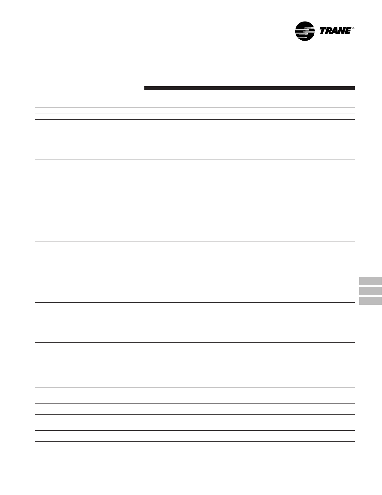
123456789101112
WCC030FD00BA
PRODUCT TYPE
TC = Package Cooling
WC = Package Heat Pumps
Selection
Procedure
Model Number Nomenclature
PRODUCT
SERVICE CHANGE
AIRFLOW CONFIGURATION
C = Convertible
NOMINAL NET COOLING
CAPACITY
030 = 30 MBh
040 = 40 MBh
050 = 50 MBh
MAJOR DESIGN MODIFICATION
F = Impack
MINOR DESIGN
MODIFICATION
FACTORY INSTALLED OPTIONS
EXAMPLES:
0 = No factory installed options
AUXILIARY HEATING CAPACITY
Ø = No Auxiliary Heat (from Factory)
ELECTRICAL CHARACTERISTICS
D = 380-415V/3/50
IPB-99-7-EN-10-6-99 7
Page 8
General
Data English Units
MODEL
RA TED VOL TS/PH/HZ
A.R.I. RATING
RATINGS (COOLING)
BTUH
INDOOR AIR FLOW (CFM)
POWER INPUT (kW)
EER-95 (BTU/WATT-HR.)
EER-82
NOISE RATING NO.
RATINGS (HEATING)
(HIGH TEMP.) BTUH - COP
POWER INPUT (kW)
(LOW TEMP.) BTUH - COP
POWER INPUT (kW)
HSPF (BTU/WATT-HR.)
POWER CONNS. — V/PH/HZ
MIN. BRCH. CIR. AMPACITY
FUSE SIZE - MAX.(AMPS)
FUSE SIZE - RECMD. (AMPS)
COMPRESSOR
NO. USED - NO. SPEEDS
VOLTS/PH/HZ
R.L. AMPS
L.R. AMPS
BRCH. CIR. SELEC. CUR. AMPS
OUTDOOR COIL — TYPE
ROWS / F.P.I.
F ACE AREA (SQ. FT.)
TUBE SIZE (IN.)
REFRIGERANT CONTROL
INDOOR COIL — TYPE
ROWS / F.P.I.
F ACE AREA (SQ. FT.)
TUBE SIZE (IN.)
REFRIGERANT CONTROL
DRAIN CONN. SIZE (IN.)
DUCT CONNECTIONS
OUTDOOR FAN — TYPE
NO. USED / DIA. (IN.)
TYPE DRIVE / NO. SPEEDS
CFM @ 0.0 IN. W.G.
NO. MOTORS - HP
MOTOR SPEED R.P.M.
VOLTS/PH/HZ
F.L. AMPS - L.R. AMPS
INDOOR FAN — TYPE
DIA. X WIDTH (IN.)
NO. USED
DRIVE / SPEEDS (NO.)
CFM VS. IN. W.G.
NO. MOTORS - HP
MOTOR SPEED R.P.M.
VOLTS/PH/HZ
F.L. AMPS - L.R. AMPS
FILTER — FURNISHED?
TYPE RECOMMENDED
NO. - SIZE - THICKNESS
REFRIGERANT
CHARGE (LBS. OF R-22)
DIMENSIONS
CRATED (IN.)
UNCRATED
WEIGHT
SHIPPING (LBS.) / NET (LBS.)
NOTES:
1
RATED IN ACCORDANCE WITH A.R.I. STANDARD 210/240.
2
CALCULATED IN ACCORDANCE WITH A.R.I. STANDARD 270.
3
CALCULATED IN ACCORDANCE WITH CURRENTLY PREVAILING NATL. ELECTRIC CODE.
4
STANDARD AIR - DRY COIL - OUTDOOR
1
6
2
1
6
3
4
5
WCC030FD00B
380-415/3/50
31000
1000
3.12
9.50
10.90
8.0
29600 - 3.12
2.78
15600 - 2.00
2.29
380-415/3/50
10.2
15
15
1 - 1
5.7
51
4.2
PLATE FIN
2 / 15
8.62
PLATE FIN
3 / 15
3.96
1 / 18
DIRECT / 1
2040
1 - 1/2
900
1.7 - 3.8
10 X 9
1
DIRECT / 2
1 - 1/3
900
1.1 - 2.6
NO
3 - 10 x 25
8.2 LBS.
406 / 366
®
CLIMATUFF
380-415/3/50
3/8 COPPER
TXV BLEED
3/8 COPPER
ORIFICE - .071
3/4 FEMALE NPT
SEE OUTLINE DRAWING
PROPELLER
380-415/1/50
CENTRIFUGAL
SEE FAN PERFORMANCE TABLE
380-415/1/50
THROW AWAY
H X W X D
35-1/4 X 38 X 57
SEE OUTLINE DRAWING
WCC040FD00B
380-415/3/50
39600
1325
4.10
9.70
10.95
8.4
39400 - 3.18
3.66
20700 - 2.06
2.96
6.80
380-415/3/50
13.8
20
20
1 -
8.0
51
7.1
PLATE FIN
2 / 15
14.0
3/8
PLATE FIN
4 / 15
5.4
3/8
1 / 22
DIRECT / 1
2830
1 - 1/2
900
1.7 - 3.8
11.0 X 11.0
1
DIRECT / 2
1 - 3/4
900
2.1 - 4.8
NO
3 - 10 x 25
13.0 LBS
561 / 521
®
SEE OUTLINE DRAWING
SEE FAN PERFORMANCE TABLE
SEE OUTLINE DRAWING
CLIMATUFF
380-415/3/50
TXV BLEED
ORIFICE- .082
3/4 FEMALE
SEE OUTLINE DRAWING
PROPELLER
380-415/1/50
CENTRIFUGAL
SEE FAN PERFORMANCE TABLE
380-415/1/50
THROWAWAY
H X W X D
39-3/8 X 47 X 66
SEE OUTLINE DRAWING
5
STANDARD AIR - WET COIL - INDOOR
6
RATED IN ACCORDANCE WITH D.O.E. TEST PROCEDURE. HSPF IS AT THE
MINIMUM DESIGN REQUIREMENT FOR REGION IV.
WCC050FD00B
380-415/3/50
51600
1675
5.53
9.35
11.15
8.4
53600 - 3.18
4.91
31300 - 2.16
4.21
6.80
380-415/3/50
16.3
25
25
1 -
9.8
71
10.0
PLATE FIN
2 / 15
14.0
3/8
PLATE FIN
4 / 15
5.4
3/8
1 / 22
DIRECT / 1
2830
1 - 1/2
900
1.7 - 3.8
11.0 X 11.0
1
DIRECT / 2
1 - 3/4
900
2.1 - 4.8
NO
3 - 10 x 25
12.0 LBS
579 / 539
®
CLIMATUFF
380-415/3/50
TXV BLEED
ORIFICE - .096
3/4 FEMALE
PROPELLER
380-415/1/50
CENTRIFUGAL
380-415/1/50
THROWAWAY
H X W X D
39-3/8 X 47 X 66
8 IPB-99-7-EN-10-6-99
Page 9
General
Data Metric Units
MODEL
RA TED VOL TS/PH/HZ
A.R.I. RATING
RATINGS (COOLING)
BTUH
INDOOR AIR FLOW (CMH)
POWER INPUT (kW)
EER-95 (BTU/WATT-HR.)
EER-82
NOISE RATING NO.
RATINGS (HEATING)
(HIGH TEMP.) CAPACITY (WATTS) - COP
POWER INPUT (kW)
(LOW TEMP.) CAPACITY (WATTS) - COP
POWER INPUT (kW)
HSPF (BTU/WATT-HR.)
POWER CONNS. — V/PH/HZ
MIN. BRCH. CIR. AMPACITY
FUSE SIZE - MAX.(AMPS)
FUSE SIZE - RECMD. (AMPS)
COMPRESSOR
NO. USED - NO. SPEEDS
VOLTS/PH/HZ
R.L. AMPS
L.R. AMPS
BRCH. CIR. SELEC. CUR. AMPS
OUTDOOR COIL — TYPE
ROWS / FINS PER MILLIMETER
FACE AREA (SQ. M)
TUBE SIZE (IN.)
REFRIGERANT CONTROL
INDOOR COIL — TYPE
ROWS / FINS PER MILLIMETER
FACE AREA (SQ. M)
TUBE SIZE (IN.)
REFRIGERANT CONTROL
DRAIN CONN. SIZE (IN.)
DUCT CONNECTIONS
OUTDOOR FAN — TYPE
NO. USED / DIA. (MM)
TYPE DRIVE / NO. SPEEDS
CMH @ 0.0 PASCALS
NO. MOTORS - HP
MOTOR SPEED R.P.M.
VOLTS/PH/HZ
F.L. AMPS - L.R. AMPS
INDOOR FAN — TYPE
DIA. X WIDTH (MM)
NO. USED
DRIVE / SPEEDS (NO.)
CMH VS. PASCALS
NO. MOTORS - HP
MOTOR SPEED R.P.M.
VOLTS/PH/HZ
F.L. AMPS - L.R. AMPS
FILTER — FURNISHED?
TYPE RECOMMENDED
NO. - SIZE - THICKNESS
REFRIGERANT
CHARGE (KG OF R-22)
DIMENSIONS
CRATED (MM)
UNCRATED
WEIGHT
SHIPPING (KG) / NET (KG)
NOTES:
1
RATED IN ACCORDANCE WITH A.R.I. STANDARD 210/240.
2
CALCULATED IN ACCORDANCE WITH A.R.I. STANDARD 270.
3
CALCULATED IN ACCORDANCE WITH CURRENTLY PREVAILING NATL. ELECTRIC CODE.
4
STANDARD AIR - DRY COIL - OUTDOOR
1
6
2
1
6
3
4
5
WCC030FD00B
380-415/3/50
9085
1690
3.12
9.50 / 10.00
10.90
8.0
8675 - 3.12
2.78
4572 - 2.00
2.29
6.80
380-415/3/50
10.2
15
15
CLIMATUFF
380-415/3/50
3/8 COPPER
3/8 COPPER
ORIFICE - .071
3/4 FEMALE NPT
SEE OUTLINE DRAWING
PROPELLER
380-415/1/50
CENTRIFUGAL
SEE F AN PERFORMANCE TABLE
380-415/1/50
THROWAWAY
H X W X D
895 X 965 X 1448
SEE OUTLINE DRAWING
®
1 - 1
5.7
51
4.2
PLATE FIN
2 / .591
.801
TXV BLEED
PLATE FIN
3 / .591
.368
1 / 457
DIRECT / 1
3448
1 - 1/2
900
1.7 - 3.8
254 X 229
1
DIRECT / 2
1 - 1/3
900
1.1 - 2.6
NO
3 - 254 x 635
3.72 KG
184 / 166
WCC040FD00B
380-415/3/50
11606
2240
4.10
9.70 / 10.00
10.95
8.4
11547 - 3.18
3.66
6067 - 2.06
2.96
6.80
380-415/3/50
13.8
20
20
CLIMATUFF
380-415/3/50
ORIFICE- .082
3/4 FEMALE
SEE OUTLINE DRAWING
PROPELLER
380-415/1/50
CENTRIFUGAL
SEE FAN PERFORMANCE TABLE
380-415/1/50
THROW AWAY
H X W X D
1000 X 1194 X 1676
SEE OUTLINE DRAWING
5
STANDARD AIR - WET COIL - INDOOR
6
RATED IN ACCORDANCE WITH D.O.E. TEST PROCEDURE. HSPF IS AT THE
MINIMUM DESIGN REQUIREMENT FOR REGION IV.
®
1 -
8.0
51
7.1
PLATE FIN
2 / .591
1.30
3/8
TXV BLEED
PLATE FIN
4 / .591
.502
3/8
1 / 559
DIRECT / 1
4785
1 - 1/2
900
1.7 - 3.8
279 X 279
1
DIRECT / 2
1 - 3/4
900
2.1 - 4.8
NO
3 - 254 x 635
5.90 KG
254 / 236
SEE OUTLINE DRAWING
SEE FAN PERFORMANCE TABLE
1000 X 1194 X 1676
SEE OUTLINE DRAWING
WCC050FD00B
380-415/3/50
15122
2830
5.53
9.35 / 10.00
11.15
8.4
15709 - 3.18
4.91
9173 - 2.16
4.21
6.80
380-415/3/50
16.3
25
25
CLIMATUFF
380-415/3/50
ORIFICE - .096
3/4 FEMALE
PROPELLER
380-415/1/50
CENTRIFUGAL
380-415/1/50
THROWAWAY
H X W X D
®
1 -
9.8
71
10.0
PLATE FIN
2 / .591
1.30
3/8
TXV BLEED
PLATE FIN
4 / .591
.502
3/8
1 / 559
DIRECT / 1
4783
1 - 1/2
900
1.7 - 3.8
279 X 279
1
DIRECT / 2
1 - 3/4
900
2.1 - 4.8
NO
3 - 254 x 635
5.44 KG
263 / 244
IPB-99-7-EN-10-6-99 9
Page 10

Performance
Data Cooling English Units
O.D. I.D. TOTAL SENS. CAP. AT ENTERING D.B. TEMP. COMPR.
D.B. W.B. CAP. 72 74 76 78 80 KW
59 29.3 23.6 25.4 27.2 29.1 30.0* 2.29
85 63 31.5 20.1 21.9 23.7 25.5 27.3 2.37
67 33.8 16.2 18.0 19.8 21.6 23.4 2.44
71 36.2 12.3 14.1 15.9 17.7 19.5 2.52
59 28.6 23.3 25.1 26.9 28.7* 29.4* 2.41
90 63 30.8 19.8 21.6 23.4 25.2 27.0 2.48
67 33.0 15.9 17.7 19.5 21.3 23.1 2.56
71 35.3 11.9 13.7 15.5 17.3 19.1 2.64
59 27.9 23.0 24.8 26.6 28.2* 28.8* 2.53
95 63 30.0 19.5 21.3 23.1 24.9 26.7 2.60
67 32.2 15.6 17.4 19.2 21.0 22.8 2.67
71 34.4 11.6 13.4 15.2 17.0 18.8 2.75
59 27.0 22.6 24.4 26.2 27.5* 28.1* 2.65
100 63 29.0 19.1 20.9 22.7 24.5 26.3 2.72
67 31.1 15.2 17.0 18.8 20.6 22.4 2.79
71 33.3 11.2 13.0 14.8 16.6 18.4 2.86
59 26.2 22.2 24.1 25.9 26.7* 27.4* 2.77
105 63 28.1 18.7 20.5 22.3 24.1 25.9 2.84
67 30.1 14.8 16.6 18.4 20.2 22.0 2.91
71 32.2 10.8 12.6 14.4 16.2 18.0 2.98
59 24.4 21.5 23.3 24.7* 25.3* 25.9* 3.02
115 63 26.2 17.9 19.7 21.5 23.3 25.1 3.08
67 28.1 14.0 15.8 17.6 19.4 21.2 3.14
71 30.0 10.0 11.8 13.6 15.4 17.2 3.20
WCC040FD00B AT 1325 CFM (CAPACITIES ARE GROSS IN BTUH/1000-INDOOR FAN HEAT IGNORED)
O.D. I.D. TOTAL SENS. CAP. AT ENTERING D.B. TEMP. COMPR.
D.B. W.B. CAP. 72 74 76 78 80 KW
59 37.1 30.9 33.4 35.9 37.7* 38.6* 2.60
85 63 40.0 25.9 28.5 31.0 33.5 36.1 2.68
67 42.9 20.5 23.1 25.6 28.1 30.7 2.75
71 46.0 15.0 17.6 20.1 22.6 25.1 2.84
59 36.5 30.6 33.1 35.7 37.2* 38.1* 2.73
90 63 39.3 25.7 28.2 30.7 33.3 35.8 2.81
67 42.2 20.3 22.8 25.3 27.9 30.4 2.89
71 45.2 14.8 17.3 19.8 22.4 24.9 2.97
59 35.9 30.4 32.9 35.4 36.7* 37.6* 2.87
95 63 38.6 25.4 28.0 30.5 33.0 35.5 2.95
67 41.5 20.0 22.5 25.1 27.6 30.1 3.02
71 44.5 14.5 17.0 19.6 22.1 24.6 3.10
59 34.9 29.9 32.5 35.0* 35.9* 36.8* 3.01
100 63 37.6 25.0 27.5 30.1 32.6 35.1 3.09
67 40.4 19.6 22.1 24.7 27.2 29.7 3.16
71 43.2 14.1 16.6 19.1 21.7 24.2 3.24
59 33.9 29.5 32.1 34.2* 35.1* 35.9* 3.16
105 63 36.5 24.6 27.1 29.6 32.2 34.7 3.23
67 39.2 19.2 21.7 24.2 26.8 29.3 3.30
71 42.0 13.7 16.2 18.7 21.3 23.8 3.37
59 32.0 28.7 31.3 32.6* 33.4* 34.2* 3.45
115 63 34.4 23.8 26.3 28.8 31.3 33.9 3.51
67 37.0 18.4 20.9 23.4 25.9 28.5 3.57
71 39.6 12.8 15.4 17.9 20.4 22.9 3.64
WCC030FD00B AT 1000 CFM (CAPACITIES ARE GROSS IN BTUH/1000-INDOOR FAN HEAT IGNORED)
CORRECTION FA CTORS - OTHER AIRFLOWS
AIRFLOW 875 1125
TOTAL CAP. X0.98 X1.02
SENS. CAP. X0.94 X1.05
COMPR. KW X0.99 X1.01
GROSS CAPACITY = 32200 BTUH
AIRFLOW = 1000 CFM
COMPRESSOR POWER = 2673 W ATTS
I.D. FAN POWER = 340 WATTS
O.D . FAN POWER = 250 WATTS
E.E.R. = 9.50 BTUH/WATT
NOTE: RATED WITH 25 FEET OF 7/8
* DRY COIL CONDITION (TOTAL CAPACITY = SENSIBLE CAP ACITY)
TOTAL CAP ACITY,COMP. KW AND APP. DEW PT. ARE VALID ONLY
FOR WET COIL
ALL TEMPERATURES IN DEGREES F.
AIRFLOW 1150 1500
TOTAL CAP. X0.98 X1.01
SENS. CAP. X0.94 X1.06
COMPR. KW X0.98 X1.02
GROSS CAPACITY = 41600 BTUH
AIRFLOW = 1325 CFM
COMPRESSOR POWER = 3022 W ATTS
I.D. FAN POWER = 560 WATTS
O.D . FAN POWER = 500 WATTS
E.E.R. = 9.70 BTUH/WATT
NOTE: RATED WITH 25 FEET OF 7/8
* DRY COIL CONDITION (TOTAL CAPACITY = SENSIBLE CAP ACITY)
TOTAL CAP ACITY,COMP. KW AND APP. DEW PT. ARE VALID ONLY
FOR WET COIL
ALL TEMPERATURES IN DEGREES F.
(MULTIPLY OR ADD AS INDICATED)
VALUES AT 95/80/67 RATING CONDITIONS
SUCT. AND 3/8 LIQUID LINE
CORRECTION FA CTORS - OTHER AIRFLOWS
(MULTIPLY OR ADD AS INDICATED)
VALUES AT 95/80/67 RATING CONDITIONS
SUCT. AND 3/8 LIQUID LINE
O.D. I.D. TOTAL SENS. CAP. AT ENTERING D.B. TEMP. COMPR.
WCC050FD00B AT 1675 CFM (CAPACITIES ARE GROSS IN BTUH/1000-INDOOR FAN HEAT IGNORED)
D.B. W.B. CAP. 72 74 76 78 80 KW
59 47.9 40.4 43.6 46.9 48.7* 49.9* 4.22
85 63 51.3 34.0 37.3 40.5 43.7 47.0 4.35
67 55.0 27.0 30.3 33.5 36.8 40.0 4.48
71 58.8 19.9 23.2 26.4 29.6 32.9 4.61
59 47.3 40.2 43.4 46.7 48.3* 49.4* 4.17
90 63 50.8 33.8 37.1 40.3 43.5 46.8 4.29
67 54.5 26.8 30.1 33.3 36.5 39.8 4.41
71 58.2 19.7 23.0 26.2 29.4 32.7 4.54
59 46.9 40.0 43.2 46.4 47.9* 49.0* 4.11
95 63 50.3 33.6 36.9 40.1 43.3 46.6 4.22
67 53.9 26.6 29.9 33.1 36.3 39.6 4.34
71 57.7 19.5 22.8 26.0 29.2 32.5 4.46
59 45.1 39.2 42.4 45.3* 46.5* 47.6* 4.28
100 63 48.5 32.8 36.1 39.3 42.6 45.8 4.39
67 51.9 25.9 29.1 32.3 35.6 38.8 4.51
71 55.6 18.8 22.0 25.2 28.5 31.7 4.63
59 43.4 38.4 41.7 44.0* 45.0* 46.1* 4.46
105 63 46.6 32.1 35.3 38.6 41.8 45.0 4.57
67 50.0 25.1 28.4 31.6 34.8 38.1 4.68
71 53.5 18.0 21.3 24.5 27.7 31.0 4.80
59 39.9 36.9 40.0* 41.1* 42.1* 43.1* 4.82
115 63 42.9 30.6 33.8 37.1 40.3 43.1* 4.92
67 46.0 23.6 26.9 30.1 33.3 36.6 5.03
71 49.3 16.6 19.8 23.0 26.3 29.5 5.13
CORRECTION FACTORS - OTHER AIRFLOWS
AIRFLOW 1450 1900
TOTAL CAP. X0.98 X1.01
SENS. CAP. X0.94 X1.06
COMPR. KW X0.99 X1.01
GROSS CAPACITY = 54000 BTUH
AIRFLOW = 1675 CFM
COMPRESSOR POWER = 4339 W ATTS
I.D. FAN POWER = 680 WATTS
O.D . FAN POWER = 500 WATTS
E.E.R. = 9.35 BTUH/WATT
NOTE: RATED WITH 25 FEET OF 7/8
* DRY COIL CONDITION (TOTAL CAPACITY = SENSIBLE CAP ACITY)
TOTAL CAP ACITY,COMP. KW AND APP. DEW PT. ARE VALID ONLY
FOR WET COIL
ALL TEMPERATURES IN DEGREES F.
(MULTIPLY OR ADD AS INDICATED)
VALUES AT 95/80/67 RATING CONDITIONS
SUCT. AND 3/8 LIQUID LINE
10 IPB-99-7-EN-10-6-99
Page 11

Performance
Data Cooling Metric Units
O.D. I.D. TOTAL SENS. CAP. AT ENTERING D.B. TEMP. COMPR.
D.B. W.B. CAP . 22.2 23.3 24.4 25.6 26.7 KW
15.0 8.6 6.9 7.4 8.0 8.5 8.8* 2.3
29.4 17.2 9.2 5.9 6.4 6.9 7.5 8.0 2.4
19.4 9.9 4.7 5.3 5.8 6.3 6.9 2.4
21.7 10.6 3.6 4.1 4.7 5.2 5.7 2.5
15.0 8.4 6.8 7.4 7.9 8.4* 8.6* 2.4
32.2 17.2 9.0 5.8 6.3 6.9 7.4 7.9 2.5
19.4 9.7 4.7 5.2 5.7 6.2 6.8 2.6
21.7 10.3 3.5 4.0 4.5 5.1 5.6 2.6
15.0 8.2 6.7 7.3 7.8 8.3* 8.4* 2.5
35.0 17.2 8.8 5.7 6.2 6.8 7.3 7.8 2.6
19.4 9.4 4.6 5.1 5.6 6.2 6.7 2.7
21.7 10.1 3.4 3.9 4.5 5.0 5.5 2.8
15.0 7.9 6.6 7.1 7.7 8.1* 8.2* 2.7
37.8 17.2 8.5 5.6 6.1 6.7 7.2 7.7 2.7
19.4 9.1 4.5 5.0 5.5 6.0 6.6 2.8
21.7 9.8 3.3 3.8 4.3 4.9 5.4 2.9
15.0 7.7 6.5 7.1 7.6 7.8* 8.0* 2.8
40.6 17.2 8.2 5.5 6.0 6.5 7.1 7.6 2.8
19.4 8.8 4.3 4.9 5.4 5.9 6.4 2.9
21.7 9.4 3.2 3.7 4.2 4.7 5.3 3.0
15.0 7.1 6.3 6.8 7.2* 7.4* 7.6* 3.0
46.1 17.2 7.7 5.2 5.8 6.3 6.8 7.4 3.1
19.4 8.2 4.1 4.6 5.2 5.7 6.2 3.1
21.7 8.8 2.9 3.5 4.0 4.5 5.0 3.2
WCC040FD00B AT 2250 CMH (GROSS CAP ACITY IN KILOWATTS)
O.D. I.D. TOTAL SENS. CAP. AT ENTERING D.B. TEMP. COMPR.
D.B. W.B. CAP . 22.2 23.3 24.4 25.6 26.7 KW
15.0 10.9 9.1 9.8 10.5 11.0* 11.3* 2.6
29.4 17.2 11.7 7.6 8.4 9.1 9.8 10.6 2.7
19.4 12.6 6.0 6.8 7.5 8.2 9.0 2.8
21.7 13.5 4.4 5.2 5.9 6.6 7.4 2.8
15.0 10.7 9.0 9.7 10.5 10.9* 11.2* 2.7
32.2 17.2 11.5 7.5 8.3 9.0 9.8 10.5 2.8
19.4 12.4 5.9 6.7 7.4 8.2 8.9 2.9
21.7 13.2 4.3 5.1 5.8 6.6 7.3 3.0
15.0 10.5 8.9 9.6 10.4 10.8* 11.0* 2.9
35.0 17.2 11.3 7.4 8.2 8.9 9.7 10.4 3.0
19.4 12.2 5.9 6.6 7.4 8.1 8.8 3.0
21.7 13.0 4.2 5.0 5.7 6.5 7.2 3.1
15.0 10.2 8.8 9.5 10.3* 10.5* 10.8* 3.0
37.8 17.2 11.0 7.3 8.1 8.8 9.6 10.3 3.1
19.4 11.8 5.7 6.5 7.2 8.0 8.7 3.2
21.7 12.7 4.1 4.9 5.6 6.4 7.1 3.2
15.0 9.9 8.6 9.4 10.0* 10.3* 10.5* 3.2
40.6 17.2 10.7 7.2 7.9 8.7 9.4 10.2 3.2
19.4 11.5 5.6 6.4 7.1 7.9 8.6 3.3
21.7 12.3 4.0 4.7 5.5 6.2 7.0 3.4
15.0 9.4 8.4 9.2 9.6* 9.8* 10.0* 3.5
46.1 17.2 10.1 7.0 7.7 8.4 9.2 9.9 3.5
19.4 10.8 5.4 6.1 6.9 7.6 8.4 3.6
21.7 11.6 3.8 4.5 5.2 6.0 6.7 3.6
WCC030FD00B AT 1698 CMH (GROSS CAP ACITY IN KILOWATTS)
CORRECTION FA CTORS - OTHER AIRFLOWS
AIRFLOW 1486 1910
TOTAL CAP. X0.98 X1.02
SENS. CAP. X0.94 X1.05
COMPR. KW X0.99 X1.01
GROSS CAP ACITY = 9435 KW
AIRFLOW = 1698 CMH
COMPRESSOR POWER = 2673 W ATTS
I.D. FAN POWER = 340 WATTS
O.D . FAN POWER = 250 WATTS
E.E.R. = 9.50 BTUH/WATT
NOTE: RATED WITH 7.62 METERS OF 7/8 IN.
* DRY COIL CONDITION (TOTAL CAPACITY = SENSIBLE CAP ACITY)
TOTAL CAPACITY, COMP. KW AND APP. DEW PT. ARE VALID ONLY
FOR WET COIL
ALL TEMPERATURES IN DEGREES C.
AIRFLOW 1953 2547
TOTAL CAP. X0.98 X1.01
SENS. CAP. X0.94 X1.06
COMPR. KW X0.98 X1.02
GROSS CAP ACITY =12189 KW
AIRFLOW = 2250 CMH
COMPRESSOR POWER = 3022 W ATTS
I.D. FAN POWER = 560 WATTS
O.D . FAN POWER = 500 WATTS
E.E.R. = 9.70 BTUH/WATT
NOTE: RATED WITH 7.62 METERS OF 7/8 IN.
* DRY COIL CONDITION (TOTAL CAPACITY = SENSIBLE CAP ACITY)
TOTAL CAPACITY, COMP. KW AND APP. DEW PT. ARE VALID ONLY
FOR WET COIL
ALL TEMPERATURES IN DEGREES C.
(MUL TIPLY OR ADD AS INDICATED)
VALUES AT ARI RATING CONDITIONS
SUCT. AND 3/8 IN. LIQUID LINES
CORRECTION FA CTORS - OTHER AIRFLOWS
(MUL TIPLY OR ADD AS INDICATED)
VALUES AT ARI RATING CONDITIONS
SUCT. AND 3/8 IN. LIQUID LINES
O.D. I.D. TOTAL SENS. CAP. A T ENTERING D.B. TEMP. COMPR.
WCC050FD00B AT 2845 CMH (GROSS CAP ACITY IN KILOWATTS)
D.B. W.B. CAP . 22.2 23.3 24.4 25.6 26.7 KW
15.0 14.0 11.8 12.8 13.7 14.3* 14.6* 4.2
29.4 17.2 15.0 10.0 10.9 11.9 12.8 13.8 4.3
19.4 16.1 7.9 8.9 9.8 10.8 11.7 4.5
21.7 17.2 5.8 6.8 7.7 8.7 9.6 4.6
15.0 13.9 11.8 12.7 13.7 14.2* 14.5* 4.2
32.2 17.2 14.9 9.9 10.9 11.8 12.7 13.7 4.3
19.4 16.0 7.9 8.8 9.8 10.7 11.7 4.4
21.7 17.1 5.8 6.7 7.7 8.6 9.6 4.5
15.0 13.7 11.7 12.7 13.6 14.0* 14.4* 4.1
35.0 17.2 14.7 9.8 10.8 11.7 12.7 13.7 4.2
19.4 15.8 7.8 8.8 9.7 10.6 11.6 4.3
21.7 16.9 5.7 6.7 7.6 8.6 9.5 4.5
15.0 13.2 11.5 12.4 13.3* 13.6* 13.9* 4.3
37.8 17.2 14.2 9.6 10.6 11.5 12.5 13.4 4.4
19.4 15.2 7.6 8.5 9.5 10.4 11.4 4.5
21.7 16.3 5.5 6.4 7.4 8.4 9.3 4.6
15.0 12.7 11.3 12.2 12.9* 13.2* 13.5* 4.5
40.6 17.2 13.7 9.4 10.3 11.3 12.2 13.2 4.6
19.4 14.6 7.4 8.3 9.3 10.2 11.2 4.7
21.7 15.7 5.3 6.2 7.2 8.1 9.1 4.8
15.0 11.7 10.8 11.7* 12.0* 12.3* 12.6* 4.8
46.1 17.2 12.6 9.0 9.9 10.9 11.8 12.6* 4.9
19.4 13.5 6.9 7.9 8.8 9.8 10.7 5.0
21.7 14.4 4.9 5.8 6.7 7.7 8.6 5.1
IPB-99-7-EN-10-6-99 11
CORRECTION FA CTORS - OTHER AIRFLOWS
AIRFLOW 2462 3227
TOTAL CAP. X0.98 X1.01
SENS. CAP. X0.94 X1.06
COMPR. KW X0.99 X1.01
GROSS CAP ACITY =15822 KW
AIRFLOW = 2845 CMH
COMPRESSOR POWER = 4339 W ATTS
I.D. FAN POWER = 680 WATTS
O.D . FAN POWER = 500 WATTS
E.E.R. = 9.35 BTUH/WATT
NOTE: RATED WITH 7.62 METERS OF 7/8 IN.
* DRY COIL CONDITION (TOTAL CAPACITY = SENSIBLE CAP ACITY)
TOTAL CAPACITY,COMP. KW AND APP. DEW PT. ARE VALID ONL Y
FOR WET COIL
ALL TEMPERATURES IN DEGREES C.
(MUL TIPLY OR ADD AS INDICATED)
VALUES AT ARI RATING CONDITIONS
SUCT. AND 3/8 IN. LIQUID LINES
Page 12

Performance
Data Heating English Units
O.D. HEA TING CAPACITY (BTUH/1000) AT TOTAL POWER IN KILOWATTS AT
TEMP . INDICATED INDOOR DRY BULB TEMP. INDICATED INDOOR DRY BULB TEMP .
F . 60 70 75 80 60 70 75 80
-18 7.94 7.70 7.57 7.45 1.62 1.69 1.72 1.75
-13 9.10 8.83 8.69 8.55 1.70 1.77 1.81 1.84
-8 10.3 9.95 9.80 9.64 1.78 1.86 1.90 1.93
-3 11.4 11.1 10.9 10.7 1.86 1.94 1.98 2.02
2 12.6 12.2 12.0 11.8 1.94 2.03 2.07 2.12
7 13.8 13.3 13.1 12.9 2.02 2.11 2.16 2.21
12 14.9 14.5 14.2 14.0 2.10 2.20 2.25 2.30
17 16.1 15.6 15.4 15.1 2.18 2.29 2.34 2.39
22 18.0 17.4 17.2 16.9 2.26 2.37 2.42 2.47
27 19.9 19.3 19.0 18.7 2.34 2.45 2.50 2.56
32 21.8 21.1 20.8 20.4 2.41 2.53 2.59 2.65
37 23.7 22.9 22.6 22.2 2.49 2.61 2.67 2.73
42 25.5 24.8 24.4 24.0 2.57 2.69 2.76 2.82
47 30.5 29.6 29.1 28.7 2.66 2.79 2.85 2.91
52 32.9 31.9 31.4 30.9 2.73 2.87 2.94 3.00
57 35.4 34.3 33.7 33.2 2.81 2.95 3.02 3.09
62 37.8 36.6 36.0 35.4 2.89 3.04 3.11 3.18
67 40.2 38.9 38.3 37.7 2.97 3.12 3.19 3.27
72 42.6 41.3 40.6 39.9 3.05 3.20 3.28 3.35
WCC040FD00B AT 1325 CFM
O.D . HEATING CAPACITY (BTUH/1000) AT TOTAL POWER IN KILOWATTS AT
TEMP. INDICATED INDOOR DRY BULB TEMP. INDICATED INDOOR DRY BULB TEMP.
F . 60 70 75 80 60 70 75 80
-18 10.5 10.2 10.1 9.97 2.27 2.36 2.40 2.45
-13 12.1 11.7 11.6 11.4 2.35 2.45 2.49 2.54
-8 13.6 13.2 13.1 12.9 2.43 2.53 2.58 2.64
-3 15.1 14.7 14.5 14.3 2.51 2.62 2.67 2.73
2 16.6 16.2 16.0 15.8 2.58 2.70 2.76 2.82
7 18.2 17.7 17.5 17.3 2.66 2.79 2.85 2.91
12 19.7 19.2 19.0 18.7 2.74 2.87 2.94 3.01
17 21.2 20.7 20.4 20.2 2.82 2.96 3.03 3.10
22 23.8 23.2 22.9 22.6 2.93 3.07 3.15 3.22
27 26.4 25.8 25.4 25.1 3.04 3.19 3.26 3.34
32 29.0 28.3 27.9 27.5 3.14 3.30 3.38 3.46
37 31.6 30.8 30.4 30.0 3.25 3.42 3.50 3.58
42 34.2 33.3 32.9 32.4 3.36 3.53 3.62 3.70
47 40.5 39.4 38.9 38.3 3.48 3.66 3.75 3.84
52 43.7 42.5 41.9 41.4 3.59 3.78 3.87 3.96
57 46.9 45.6 45.0 44.4 3.70 3.89 3.99 4.09
62 50.1 48.8 48.1 47.4 3.81 4.01 4.11 4.21
67 53.3 51.9 51.2 50.4 3.92 4.13 4.23 4.33
72 56.5 55.0 54.2 53.5 4.03 4.24 4.35 4.46
WCC030FD00B AT 1000 CFM
CORRECTION FA CTORS - OTHER AIRFLOWS
(VALUE AT 1000 CFM TIMES CORR. F A CTOR
AIRFLOW 870 1130
HEATING CAP. X0.98 X1.02
COMPR. KW X1.02 X0.98
VALUES AT ARI RATING CONDITIONS OF:
AIRFLOW = 1000 CFM
HEATING CAP. (HIGH TEMP.) = 29600 BTUH
HEATING CAP. (LOW TEMP.) = 15600 BTUH
COMPR. POWER (HIGH TEMP.) = 2195 WATTS
COMPR. POWER (LOW TEMP.) = 1695 WATTS
COEFF. OF PERF. (HIGH TEMP.) = 3.12
COEFF. OF PERF. (LOW TEMP.) = 2.00
OUTDOOR FAN PO WER = 250 WATTS
INDOOR FAN PO WER = 340 WATTS
NOTE:RATED WITH 25 FEET OF 7/8
AIRFLOW 1153 1497
HEATING CAP. X0.98 X1.01
COMPR. KW X1.02 X0.98
VALUES AT ARI RATING CONDITIONS OF:
AIRFLOW = 1325 CFM
HEATING CAP. (HIGH TEMP.) = 39400 BTUH
HEATING CAP. (LOW TEMP.) = 20700 BTUH
COMPR. POWER (HIGH TEMP.) = 2600 WATTS
COMPR. POWER (LOW TEMP.) = 1900 WATTS
COEFF. OF PERF. (HIGH TEMP.) = 3.18
COEFF. OF PERF. (LOW TEMP.) = 2.06
OUTDOOR FAN PO WER = 500 WATTS
INDOOR FAN PO WER = 560 WATTS
NOTE:RATED WITH 25 FEET OF 7/8
= VALUE AT NEW AIRFLOW)
70&47/43 (HIGH TEMP. POINT)
70&17/15 (LOW TEMP. POINT)
SUCTION AND 3/8 LIQUID LINE
CORRECTION FA CTORS - OTHER AIRFLOWS
(VALUE AT 1325 CFM TIMES CORR. F A CTOR
= VALUE AT NEW AIRFLOW)
70&47/43 (HIGH TEMP. POINT)
70&17/15 (LOW TEMP. POINT)
SUCTION AND 3/8 LIQUID LINE
O.D . HEATING CAPACITY (BTUH/1000) AT TOTAL POWER IN KILOWATTS AT
TEMP. INDICATED INDOOR DRY BULB TEMP. INDICATED INDOOR DRY BULB TEMP.
F . 60 70 75 80 60 70 75 80
-18 14.3 13.9 13.8 13.6 2.94 3.06 3.12 3.18
-13 16.8 16.4 16.2 16.0 3.09 3.23 3.30 3.36
-8 19.4 18.9 18.7 18.4 3.25 3.40 3.47 3.55
-3 21.9 21.4 21.1 20.8 3.41 3.57 3.65 3.73
2 24.5 23.9 23.6 23.3 3.57 3.74 3.82 3.91
7 27.0 26.3 26.0 25.7 3.72 3.91 4.00 4.09
12 29.5 28.8 28.5 28.1 3.88 4.08 4.17 4.27
17 32.1 31.3 30.9 30.5 4.04 4.25 4.35 4.45
22 33.9 33.1 32.7 32.3 4.08 4.29 4.39 4.50
27 35.8 34.9 34.5 34.0 4.12 4.33 4.44 4.54
32 37.7 36.7 36.2 35.8 4.16 4.37 4.48 4.59
37 39.5 38.5 38.0 37.5 4.20 4.42 4.53 4.63
42 41.4 40.3 39.8 39.3 4.24 4.46 4.57 4.68
47 55.0 53.6 52.9 52.2 4.69 4.94 5.06 5.19
52 58.8 57.3 56.6 55.8 4.80 5.06 5.18 5.31
57 62.6 61.0 60.2 59.4 4.91 5.17 5.30 5.43
62 66.5 64.8 63.9 63.0 5.02 5.29 5.42 5.55
67 70.3 68.5 67.6 66.7 5.13 5.40 5.54 5.68
72 74.1 72.2 71.2 70.3 5.24 5.52 5.66 5.80
WCC050FD00B AT 1675 CFM
12 IPB-99-7-EN-10-6-99
CORRECTION FA CTORS - OTHER AIRFLOWS
(VALUE AT 1675 CFM TIMES CORR. F A CTOR
AIRFLOW 1457 1893
HEATING CAP. X0.99 X1.01
COMPR. KW X1.02 X0.98
VALUES AT ARI RATING CONDITIONS OF:
AIRFLOW = 1675 CFM
HEATING CAP. (HIGH TEMP.) = 53600 BTUH
HEATING CAP. (LOW TEMP.) = 31300 BTUH
COMPR. POWER (HIGH TEMP.) = 3760 WATTS
COMPR. POWER (LOW TEMP.) = 3065 WATTS
COEFF. OF PERF. (HIGH TEMP.) = 3.18
COEFF. OF PERF. (LOW TEMP.) = 2.16
OUTDOOR FAN PO WER = 500 WATTS
INDOOR FAN PO WER = 680 WATTS
NOTE:RATED WITH 25 FEET OF 7/8
= VALUE AT NEW AIRFLOW)
70&47/43 (HIGH TEMP. POINT)
70&17/15 (LOW TEMP. POINT)
SUCTION AND 3/8 LIQUID LINE
Page 13

Performance
Data Heating Metric Units
O.D . HEATING CAP A CITY IN KILOWATTS AT TOTAL POWER IN KILOWATTS AT
TEMP. INDICATED INDOOR DRY BULB TEMP. INDICATED INDOOR DR Y B ULB TEMP.
C. 23.3 31.7 35.8 40.0 23.3 31.7 35.8 40.0
-27.8 2.33 2.26 2.22 2.18 1.62 1.69 1.72 1.75
-25.0 2.67 2.59 2.55 2.51 1.70 1.77 1.81 1.84
-22.2 3.02 2.92 2.87 2.82 1.78 1.86 1.90 1.93
-19.4 3.34 3.25 3.19 3.14 1.86 1.94 1.98 2.02
-16.7 3.69 3.57 3.52 3.46 1.94 2.03 2.07 2.12
-13.9 4.04 3.90 3.84 3.78 2.02 2.11 2.16 2.21
-11.1 4.37 4.25 4.16 4.10 2.10 2.20 2.25 2.30
-8.3 4.72 4.57 4.51 4.42 2.18 2.29 2.34 2.39
-5.6 5.27 5.10 5.04 4.95 2.26 2.37 2.42 2.47
-2.8 5.83 5.65 5.57 5.48 2.34 2.45 2.50 2.56
0.0 6.39 6.18 6.09 5.98 2.41 2.53 2.59 2.65
2.8 6.94 6.71 6.62 6.50 2.49 2.61 2.67 2.73
5.6 7.47 7.27 7.15 7.03 2.57 2.69 2.76 2.82
8.3 8.94 8.67 8.53 8.41 2.66 2.79 2.85 2.91
11.1 9.64 9.35 9.20 9.05 2.73 2.87 2.94 3.00
13.9 10.37 10.05 9.87 9.73 2.81 2.95 3.02 3.09
16.7 11.08 10.72 10.55 10.37 2.89 3.04 3.11 3.18
19.4 11.78 11.40 11.22 11.05 2.97 3.12 3.19 3.27
22.2 12.48 12.10 11.90 11.69 3.05 3.20 3.28 3.35
WCC040FD00B AT 0.63 CUBIC METERS/SEC
O.D. HEATING CAP A CITY IN KILOWATTS AT TOTAL POWER IN KILOWATTS AT
TEMP . INDICATED INDOOR DRY BULB TEMP. INDICATED INDOOR DRY BULB TEMP .
C. 23.3 31.7 35.8 40.0 23.3 31.7 35.8 40.0
-27.8 3.08 2.99 2.96 2.92 2.27 2.36 2.40 2.45
-25.0 3.55 3.43 3.40 3.34 2.35 2.45 2.49 2.54
-22.2 3.98 3.87 3.84 3.78 2.43 2.53 2.58 2.64
-19.4 4.42 4.31 4.25 4.19 2.51 2.62 2.67 2.73
-16.7 4.86 4.75 4.69 4.63 2.58 2.70 2.76 2.82
-13.9 5.33 5.19 5.13 5.07 2.66 2.79 2.85 2.91
-11.1 5.77 5.63 5.57 5.48 2.74 2.87 2.94 3.01
-8.3 6.21 6.07 5.98 5.92 2.82 2.96 3.03 3.10
-5.6 6.97 6.80 6.71 6.62 2.93 3.07 3.15 3.22
-2.8 7.74 7.56 7.44 7.35 3.04 3.19 3.26 3.34
0.0 8.50 8.29 8.17 8.06 3.14 3.30 3.38 3.46
2.8 9.26 9.02 8.91 8.79 3.25 3.42 3.50 3.58
5.6 10.02 9.76 9.64 9.49 3.36 3.53 3.62 3.70
8.3 11.87 11.54 11.40 11.22 3.48 3.66 3.75 3.84
11.1 12.80 12.45 12.28 12.13 3.59 3.78 3.87 3.96
13.9 13.74 13.36 13.18 13.01 3.70 3.89 3.99 4.09
16.7 14.68 14.30 14.09 13.89 3.81 4.01 4.11 4.21
19.4 15.62 15.21 15.00 14.77 3.92 4.13 4.23 4.33
22.2 16.55 16.11 15.88 15.68 4.03 4.24 4.35 4.46
WCC030FD00B AT 0.47 CUBIC METERS/SEC
CORRECTION FA CTORS - OTHER AIRFLOWS
(VALUE AT 0.47 CMS TIMES CORR. F A CTOR
AIRFLOW 0.41 0.53
HEATING CAP. X0.98 X1.02
COMPR. KW X1.02 X0.98
VALUES AT ARI RATING CONDITIONS OF:
AIRFLOW = 0.47 CMS
HEATING CAP. (HIGH TEMP.) = 8.67 KILOWATTS
HEATING CAP. (LOW TEMP.) = 4.57 KILOWA TTS
COMPR. POWER (HIGH TEMP.) = 2195 WATTS
COMPR. POWER (LO W TEMP.) = 1695 W ATTS
COEFF. OF PERF. (HIGH TEMP.) = 3.12
COEFF. OF PERF. (LOW TEMP.) = 2.00
OUTDOOR FAN PO WER = 250 WATTS
INDOOR FAN PO WER = 340 WATTS
NOTE:RATED WITH 7.62 METERS OF 7/8
AIRFLOW 0.54 0.71
HEATING CAP. X0.98 X1.01
COMPR. KW X1.02 X0.98
VALUES AT ARI RATING CONDITIONS OF:
AIRFLOW = 0.63 CMS
HEA TING CAP . (HIGH TEMP .) = 11.55 KILO WA TTS
HEA TING CAP . (LO W TEMP.) = 6.07 KILOWA TTS
COMPR. POWER (HIGH TEMP.) = 2600 WATTS
COMPR. POWER (LO W TEMP.) = 1900 W ATTS
COEFF. OF PERF. (HIGH TEMP.) = 3.18
COEFF. OF PERF. (LOW TEMP.) = 2.06
OUTDOOR FAN PO WER = 500 WATTS
INDOOR FAN PO WER = 560 WATTS
NOTE:RATED WITH 7.62 METERS OF 7/8
= VALUE AT NEW AIRFLOW)
21&8/6 (HIGH TEMP. POINT)
21&(-8)/(-9) (LOW TEMP. POINT)
SUCTION AND 3/8 LIQUID LINE
CORRECTION FA CTORS - OTHER AIRFLOWS
(VALUE AT 0.63 CMS TIMES CORR. F A CTOR
= VALUE AT NEW AIRFLOW)
21&8/6 (HIGH TEMP. POINT)
21&(-8)/(-9) (LOW TEMP. POINT)
SUCTION AND 3/8 LIQUID LINE
O.D. HEA TING CAP A CITY IN KILOW A TTS A T TOTAL PO WER IN KILOW A TTS A T
TEMP . INDICA TED INDOOR DR Y BULB TEMP . INDICATED INDOOR DRY BULB TEMP .
C. 23.3 31.7 35.8 40.0 23.3 31.7 35.8 40.0
-27.8 4.19 4.07 4.04 3.98 2.94 3.06 3.12 3.18
-25.0 4.92 4.81 4.75 4.69 3.09 3.23 3.30 3.36
-22.2 5.68 5.54 5.48 5.39 3.25 3.40 3.47 3.55
-19.4 6.42 6.27 6.18 6.09 3.41 3.57 3.65 3.73
-16.7 7.18 7.00 6.91 6.83 3.57 3.74 3.82 3.91
-13.9 7.91 7.71 7.62 7.53 3.72 3.91 4.00 4.09
-11.1 8.64 8.44 8.35 8.23 3.88 4.08 4.17 4.27
-8.3 9.41 9.17 9.05 8.94 4.04 4.25 4.35 4.45
-5.6 9.93 9.70 9.58 9.46 4.08 4.29 4.39 4.50
-2.8 10.49 10.23 10.11 9.96 4.12 4.33 4.44 4.54
0.0 11.05 10.75 10.61 10.49 4.16 4.37 4.48 4.59
2.8 11.57 11.28 11.13 10.99 4.20 4.42 4.53 4.63
5.6 12.13 11.81 11.66 11.51 4.24 4.46 4.57 4.68
8.3 16.11 15.70 15.50 15.29 4.69 4.94 5.06 5.19
11.1 17.23 16.79 16.58 16.35 4.80 5.06 5.18 5.31
13.9 18.34 17.87 17.64 17.40 4.91 5.17 5.30 5.43
16.7 19.48 18.99 18.72 18.46 5.02 5.29 5.42 5.55
19.4 20.60 20.07 19.81 19.54 5.13 5.40 5.54 5.68
22.2 21.71 21.15 20.86 20.60 5.24 5.52 5.66 5.80
IPB-99-7-EN-10-6-99 13
WCC050FD00B A T 0.79 CUBIC METERS/SEC
CORRECTION FA CTORS - O THER AIRFLOWS
(VALUE AT 0.79 CMS TIMES CORR. F ACT OR
AIRFLOW 0.69 0.89
HEATING CAP. X0.99 X1.01
COMPR. KW X1.02 X0.98
VALUES AT ARI RATING CONDITIONS OF:
21&8/6 (HIGH TEMP. POINT)
21&(-8)/(-9) (LOW TEMP. POINT)
AIRFLOW = 0.79 CMS
HEA TING CAP . (HIGH TEMP .) = 15.71 KILO WA TTS
HEA TING CAP . (LO W TEMP.) = 9.17 KILOWA TTS
COMPR. POWER (HIGH TEMP.) = 3760 WATTS
COMPR. POWER (LO W TEMP.) = 3065 W ATTS
COEFF. OF PERF. (HIGH TEMP.) = 3.18
COEFF. OF PERF. (LOW TEMP.) = 2.16
OUTDOOR FAN PO WER = 500 WATTS
INDOOR FAN PO WER = 680 WATTS
NOTE:RATED WITH 7.62 METERS OF 7/8
= V ALUE A T NEW AIRFLO W)
SUCTION AND 3/8 LIQUID LINE
Page 14

Performance
Data
Indoor Blower Performances WCC030FD
Air Flow
CFM (CMH)
[2]
750 (1270) 0.58 (145) 220 0.17 0.43 (107) 218 0.17
790 (1335) 0.56 (140) 227 0.17 0.39 (97) 225 0.18
830 (1400) 0.53 (132) 234 0.18 0.34 (85) 231 0. 19
880 (1490) 0.50 (125) 241 0.1 9 0.28 (70) 239 0.20
920 (1554) 0.47 (117) 247 0.20 0.20 (50) 247 0.21
960 (1622) 0.44 (110) 254 0.20 0.10 (25) 254 —
1000 (1690) 0.40 (100) 260 0.21 — — —
1040 (1757) 0.36 ( 90) 267 0.21 — — —
1080 (1825) 0.32 (80) 274 0.22 — — —
1130 (1910) 0.26 (65) 281 0.23 — — —
1170 (1977) 0.21 (52) 287 0.24 — — —
1210 (2045) 0.13 (32) 293 0.24 — — —
1250 (2112) 0.05 (12) 300 0.25 — — —
High Speed [1] Low Speed
Press IN.
W.G.
(PA)
PWR
Watts
BHP
Press IN.
W.G. (PA)
PWR
Watts
BHP
———————
———————
———————
———————
———————
———————
[1] Factory setting at HI speed [2] Wet coil, no filter, no heater
Indoor Blower Performances WCC050FD
Air Flow
CFM (CMH)
[2]
1170 (1980) 0.73 (184) 431 0. 33 0.60 (150) 414 0.29
1210 (2050) 0.70 (175) 440 0.34 0. 55 ( 137) 423 0.29
1250 (2120) 0.67 (167) 450 0.35 0. 51 ( 127) 432 0.29
1290 (2180) 0.65 (163) 459 0.36 0. 47 ( 117) 442 0.28
1330 (2250) 0.63 (157) 469 0.38 0. 42 ( 105) 451 0.28
1380 (2340) 0.59 (148) 478 0.39 0.39 (97) 460 0.27
1420 (2400) 0.56 (140) 488 0.40 0.35 (87) 469 0.27
1460 (2470) 0.53 (132) 498 0.41 0.31 (77) 479 0.27
1500 (2540) 0.51 (127) 508 0.42 0.28 (70) 488 0.2 6
1540 (2600) 0.48 (120) 519 0.43 0.24 (60) 497 0.2 5
1580 (2670) 0.44 (110) 530 0.44 0.21 (52) 506 0.2 5
1630 (2760) 0.40 (100) 541 0.45 0.17 (42) 516 0.24
1670 (2830) 0.37 (92) 552 0.46 0.14 (35) 525 0.23
1710 (2890) 0.33 (83) 563 0.47 0.10 (25) 534 0.23
1750 (2960) 0.28 (70) 575 0.47 0.07 (17) 544 0.23
1790 (3025) 0.24 (60) 588 0.48 — — —
1830 (3090) 0.19 (45) 601 0.49 — — —
1880 (3180) 0.15 (37) 608 0.49 — — —
1920 (3250) 0.11 (27) 620 0.50 — — —
1960 (3315) 0.07 (17) 631 0.52 — — —
[1] Factory setting at HI speed [2] Wet coil, no filter, no heater
High Speed [1] Low Speed
Press IN.
W.G. (PA)
PWR
Watts
BHP
Press IN.
W.G. (PA)
PWR
Watts
BHP
Indoor Blower Performances WCC040FD
Air Flow
CFM (CMH)
[3]
1000 (1690) — — — 0.69 (172) 356 0.27
1040 (1757) — — — 0.67 (167) 365 0.27
1080 (1825) — — — 0.64 (160) 373 0.28
1130 (1910) — — — 0.60 (150) 381 0.28
1170 (1977) 0.73 (183) 431 0.3 3 0. 57 ( 142) 389 0.29
1210 (2045) 0.70 (175) 440 0.34 0.5 3 (1 32) 398 0.29
1250 (2112) 0.67 (167) 450 0.35 0.4 9 (1 22) 40 7 0.29
1290 (2180) 0.65 (162) 459 0.36 0.4 5 (1 12) 41 7 0.29
1330 (2247) 0.63 (157) 469 0.38 0.4 0 (1 00) 42 7 0.29
1380 (2332) 0.59 (147) 478 0.39 0.35 (87) 437 0.28
1420 (2400) 0.56 (140) 488 0.40 0.28 (70) 448 0.28
1460 (2467) 0.53 (132) 498 0.41 0.19 (47) 463 0.26
1500 (2535) 0.50 (125) 508 0.42 0.10 (25) 479 0.24
1540 (2602) 0.47 (117) 518 0.43 0.01 (2.5) 49 5 0.23
1580 (2670) 0.44 (110) 528 0.44 — — —
1630 (2755) 0.41 (102) 537 0.45 — — —
1670 (2825) 0.38 (95) 547 0.46 — — —
1710 (2890) 0.35 (87) 557 0.47 — — —
1750 (2958) [2] 0.31 (77) 567 0.48 — — —
[1] Factory setting at LO speed
[2] Water Blow Off Unit
High Speed Low Speed [1]
Press IN.
W.G.
(PA)
PWR
BHP
Watts
[3] Wet coil, no filter, no heater
Press IN.
W.G. (PA )
PWR
Watts
BHP
14 IPB-99-7-EN-10-6-99
Page 15

Optional
Equipment
25% Manual Fresh Air Kit
T ypical Filter Frame
IPB-99-7-EN-10-6-99 15
Page 16

Optional
Equipment
Economizer and Rain Hood
(Downflow Applications)
ALL DIMENSIONS ARE IN INCHES (MM)
Thermostats
Two stages heating/cooling or one stage
heating/cooling thermostats are available in
either manual or automatic changeover.
Programmable Electronic
Night Setback Thermostat
Heating setback and cooling setup with 7-day,
5-1-1 programming capability. Available in
2 heating/cooling or 1 heating/cooling
versions with automatic changeover.
ECONOMIZER
MODEL
BA YEC ON054B WCC030F
BA YEC ON055B
APPLICATION
MODELS
WCC040F
WCC050F20(500)21(533)26(660)
ABC D E FGH
20
16-5/8
(500)
(420)
Controls
Field Installed Control Options
Economizer Controls
The standard equipment offering is a fixed dry
bulb changeover control. In addition to the
standard offering, there are two other field
installed control accessories.
Enthalpy Control
Replaces the dry bulb control with a solid
state dry bulb and wet bulb changeover
controller which has a fully adjustable set
point. Enthalpy control offers a higher level of
23-1/2
22-9/16
(600)
energy savings potential than the standard
dry bulb control due to the additional wet bulb
sensing capability.
Differential Enthalpy
Replaces the standard dry bulb control with
two enthalpy sensors that compare total heat
content of the indoor air and outdoor air to
determine the most efficient entering air
source. This control option offers the highest
level of energy efficiency available.
(575)
OMIT
8-5/8
22-1/4
(565)
26-1/8
(670)
25-1/8
(640)
32-1/8
(820)
(220)
12-1/8
(315)
From Dwg. 21D662389 Rev.1
1-1/2
(38)
1-3/4
(45)
16 IPB-99-7-EN-10-6-99
Page 17

Field
Wiring
WCC-F Heat Pump Models
NOTES:
1. FUSED DISCONNECT SIZE, POWER WIRING AND
GROUNDING OF EQUIPMENT MUST COMPLY
WITH CODES.
2. BE SURE POWER SUPPLY AGREES WITH
EQUIPMENT AND HEATER NAMEPLATE.
3. LOW VOLTAGE WIRING TO BE 18 AWG MINIMUM
CONDUCTOR.
4. SEE HEATER NAMEPLATE FOR CURRENT
RATING OF HEATER USED.
5. SEE UNIT AND HEATER DIAGRAM FOR
ELECTRICAL CONNECTION DETAILS.
6. IF ELECTRIC HEATER ACCESSORY IS NOT
INSTALLED OMIT THE ELECTRIC HEATER,
ASSOCIATED POWER WIRES AND THE ‘W’ AND
‘X2’ THERMOSTAT WIRES.
7. FIG. 3 DEMONSTRATES CONNECTION OF THE
OUTDOOR THERMOSTAT ACCESSORY ONLY.
FOR FURTHER UNIT CONNECTION DETAILS
REFER TO THE OTHER FIGURES.
8. THE 41A(BR) WIRE IS FIRST STAGE ELECTRIC
HEAT. IF THE ELECTRIC HEATER ACCESSORY
HAS TWO HEATING STAGES THE 41C(BR) WIRE
IS SECOND STAGE ELECTRIC HEAT.
9. WHEN THE BAYECON054A OR –055A
ECONOMIZER IS INSTALLED THE BAYRLAY003
RELAY ACCESSORY KIT IS REQUIRED TO
INTERFACE THE ECONOMIZER TO THE HEAT
PUMP FOR PROPER SYSTEM OPERATION.
WHEN THE BAYECON054B OR –055B OR 073A
ECONOMIZER IS INSTALLED, THE BAYRLAY004A
RELAY ACCESSORY KIT IS REQUIRED TO
INTERFACE THE ECONOMIZER TO THE HEAT
PUMP FOR PROPER SYSTEM OPERATION.
10. THE BAYSTAT033A OUTDOOR THERMOSTAT
ACCESSORY KIT CONTAINS A THERMOSTAT
AND A RELAY. THE RELAY IS NOT REQUIRED
TO BE USED IN THIS APPLICATION.
IPB-99-7-EN-10-6-99 17
From Dwg. 21D756978
Page 18

Field
Wiring
Wiring Diagram for WCC030,040,050FD00B Units
continued on next page
18 IPB-99-7-EN-10-6-99
From Dwg. 21D756914 P03
Page 19

Field
Wiring
Wiring Diagram for WCC030,040,050FD00B Units
IPB-99-7-EN-10-6-99 19
From Dwg. 21D756914 P03
Page 20

Dimensions
BAYCURB030A Roof Curb Outline With WCC030F Units
ALL DIMENSIONS ARE IN INCHES (MM)
MODEL NO.
WCC030F
WCC040F
WCC050F
All dimensions are in inches (mm).
AIR DUCT
OPENINGS
SUPPLY 21 (533) 16-3/4 ( 425) — —
RETURN — — 21 (533) 21-1/8 (540)
SUPPLY 21 (533) 19 (483) — —
RETURN — — 21 (533) 22-1/8 (565)
Required Clearance for Unit Installation and Roof Penetration Hole Size Required
INSULATED DECK PANS
ARE INCLUDED WITH THE
BAYCURB038A ONLY.
34
(865)
21
(533)
1
(38)
1
/
(790)
2
31
1
(38)
1
(38)
1
/
2
1
/
2
ABCD
ALL DIMENSIONS ARE IN INCHES (MM)
A
SUPPLY
1
/
4
(108)
1
53
/
(1350)
1
/
8
50
(1275)
B
D
RETURN
2
1
1
(38)
C
/
2
1
/
1
(38)
8
(38)
2
1
1
/
2
This member used
on WCC030F
models only
8
(200)
1
/
2
1
(38)
34
(865)
8
(222)
13
/16
(2.1)
14
3
/4
(355)
11/4
(32)
From Dwg. 21C729942
SERVICE CLEARANCE & PENETRATION DIMENSIONS
MODEL NO. A B C D E F
42"
30"
*12"
30"
WCC030F
WCC040F
WCC050F
* 18" (457) WITH 25% FRESH AIR ACCESSORY
30" (762) WITH ECONOMIZER
(1067)
42"
(1067)
(762)
30"
(762)
(305)
*12"
(305)
(762)
36"
(915)
44"
(1117)
50"
(1270)
25"
(635)
25"
(635)
From Dwg. 21C662039
20 IPB-99-7-EN-10-6-99
Page 21

BAYCURB034A Roof Curb Outline With WCC040,050F Units
MODEL NO.
WCC040F
WCC050F
All dimensions are in inches (mm).
AIR DUCT
OPENINGS
SUPPLY
RETURN
ABC
21
(533)19(482)
21
(533)
—
—
22-1/8
(565)
Dimensions
ALL DIMENSIONS ARE IN INCHES (MM)
1
1
/
11/
(38)
2
(32)
A
SUPPLY
4
43
(1090)
12
(305)
1
62
/
16
(1575)
11/
2
(38)
1
/2 (114)
A
RETURN
13
/
16
(21)
4
C
B
11/
2
(38)
7
17
(450)
40
(1015)
/
8
1
/
1
(38)
1
(38)
From Dwg. 21C662034
14
(355)
2
1
/
2
Required Clearance for Unit Installation and Roof Penetration Hole Size Required
SERVICE CLEARANCE DIMENSIONS
MODEL NO. A B C D
WCC040F
WCC050F
* 18" (457) WITH 25% FRESH AIR ACCESSORY
30" (762) WITH ECONOMIZER
42"
(1070)
30"
(815)
*6"
(150)
36"
(915)
ALL DIMENSIONS ARE IN INCHES (MM)
50"
(1270)
25"
(635)
From Dwg. 21C662039
IPB-99-7-EN-10-6-99 21
Page 22

Dimensions
Field Fabricated (Side X Side) Ducts — WCC030-050F Units
Installed from Above Mounting Curb
ALL DIMENSIONS ARE IN INCHES (MM)
P.V .C. Rubber Gasket Position on B AYCURB030A for Unit Placement — WCC030-050F Units
NOTES:
1. OVERLAP AND POSITION JOINTS IN P.V.C. RUBBER
GASKET.
2. AIR SEALS – APPLY P.V.C. RUBBER LAST TO INSURE
THERE IS ADEQUATE P.V.C. FOR THE WATER SEAL.
3. USE TYPICAL SEALING METHODS TO PREVENT AIR
DUCT LEAKAGE AT CURB-DUCT JOINT.
ALL DIMENSIONS ARE IN INCHES (MM)
22 IPB-99-7-EN-10-6-99
Page 23

Dimensions
WCC030-050F OUTLINE DRA WING — Fr ont
ALL DIMENSIONS ARE IN INCHES (MM)
CABINET
SIZE
"B"
"D"
"D"
IPB-99-7-EN-10-6-99 23
MODEL BAYCURB "A" "B" "C" "D" "E" "F" "G" "H"
WCC030F 030A
WCC040F
WCC050F
WCC040F
WCC050F
030A
034A
14-1/8
(360)
14-13/16
(380)
14-13/16
(380)
16-5/8
(425)36(915)34(865)
21
(535)45(1145)34(865)
21
(533)45(1145)43(1092)
29-3/16
(740)
33-3/8
(850)
33-3/8
(850)
13-3/4
(350)
13-3/4
(350)
13-3/4
(350)
——
10-1/8
(261)
——
From Dwg. 21D661772
9-7/8
(251)
Page 24

Dimensions
WCC030-050F OUTLINE DRA WING — Fr ont
ALL DIMENSIONS ARE IN INCHES (MM)
MODELABCDE F
WCC030F
WCC040F
WCC050F
55-1/4
(1405)
64-5/16
(1634)45(1145)
36
(915)
29-3/16
(740)
33-3/8
(850)
12-15/16
(330)
14-13/16
(375)
4-7/8
(122)
4-7/8
(122)
24 IPB-99-7-EN-10-6-99
KNOCKOUTS FOR 3/4" (20) AND 1-1/4" (32 ) CONDUI T
KNOCKOUTS FOR 3/4" (20) AND 1-1/2" (38 ) CONDUI T
From Dwg. 21D729945 Rev. 5
Page 25

13/8
(35)
Dimensions
WCC030-050F OUTLINE DRAWING — Rear
ALL DIMENSIONS ARE IN INCHES (MM)
MODEL
WCC030F
WCC040F
WCC050F
1
/4 (6)
1
/2 (12)
CORNER WEIGHT LBS (KG)
W1 W2 W3 W4
94
(43)73(33)80(36)
126
104
(57)
(47)
131
108
(59)
(49)
127
(58)
132
(60)
104
(47)
153
(70)
159
(72)
UNIT
WEIGHT
LBS (KG)
318
(144)
486
(220)
504
(229)
11/8
(30)
CONDENSATE DRAIN
FOR 3/4" (19) FEMALE NPT
3 (75)
3
/4 (19)
5
(16)
/8
3
(19)
/4
ABC D E F G H J K LMNP
55-1/4
(1400)36(915)
64-5/16
(1634)45(1145)
29-3/16
(750)
33-3/8
(846)
18-9/16
(470)
21-1/16
(535)
11-1/16
(280)
15-1/16
(385)
6-9/16
(170)
4-15/16
(120)
6-13/16
(170)17(430)
9-1/8
21-15/16
(230)
(550)
18-13/16
(465)24(610)
24-3/4
(628)29(736)
24-3/4
(628)29(736)
17-1/2
(445)10(250)3(75)
20
(500)14(350)
3-1/2
(90)
4-7/16
(115)
8-5/16
(210)
From Dwg. 21D729988 Rev. 10
IPB-99-7-EN-10-6-99 25
Page 26

Mechanical
Specification Options
General
The units shall be horizontal airflow as
shipped and convertible to downflow. All units
shall be factory assembled, piped, internally
wired and fully charged with R-22. Units shall
be UL listed and carry a UL label. All units
shall be factory run tested to check cooling
operation, fan and blower rotation and control
sequence. Units shall be designed to operate
at ambient temperatures between 115°F and
55°F in cooling as manufactured. Cooling
performance shall be rated in accordance
with ARI standards.
Unit Casing
All components shall be mounted in a
weather-resistant steel cabinet with an
enamel finish. Access panels shall be
provided for unit controls and indoor coil and
fans. Indoor air section compartment shall be
completely insulated with fireproof, permanent, odorless glass fiber material. Knockouts
shall be provided for utility and control
connections. Drain connections shall be
provided to accommodate indoor water runoff.
Compressor
The compressor shall be a hermetically
sealed, high efficiency Climatuff® compressor.
Internal overcurrent and over temperature
protection, internal pressure relief shall be
standard. Crankcase heaters shall be
standard on all three phase models.
Refrigeration System
All units shall have capillary tube refrigerant
control. Service pressure tap ports, and a
refrigerant line filter dryer shall be standard.
Indoor and Outdoor Coils
Coils shall be internally finned or smooth bore
3/8" copper tubes mechanically bonded to
configured aluminum plate fin as standard.
Evaporator coil leak and pressure tested to
200 psig; condenser coil tested to 450 psig.
Indoor Fan
The indoor fan shall be a forward curved,
centrifugal-type fan with a multiple-speed,
direct drive motor. Motor is permanently
lubricated and shall have built-in overload
protection.
Outdoor Fan
One, direct-drive, statically and dynamically
balanced propeller fan shall be used in a
draw-through vertical discharge configuration.
Permanently lubricated weather proof motor
shall have built-in thermal overload protection.
System Controls
System controls include condenser fan,
evaporator fan and compressor contactors.
Accessories
Roof Curb — The roof curb shall be designed
to mate with the unit and provide support and
complete weathertight installation when
properly installed. Adhesive back polyurethane sealing strips shall be provided to
ensure an airtight seal between supply and
return openings of the curb and unit. The roof
curb design allows field fabricated ductwork to
be connected directly to the curb. Curb ships
knocked down for field assembly, and includes
factory-installed wood nailer strips.
Fully Modulating Economizer — This
accessory shall be field installed and be
composed of the following items: 0-100%
fresh air damper, damper drive motor, fixed
dry bulb enthalpy control, and low voltage
pigtails for electrical connections. Solid state
enthalpy or differential enthalpy control is
optional. Economizer operations shall be
controlled by the preset position of the
enthalpy control. A barometric relief damper
shall be standard with the economizer and
provide a pressure operated damper that shall
be gravity closing and prohibit entrance of
outside air on equipment “off” cycle.
Manual Outside Air Dampers — Rain hood
and screen shall be field installed. Suitable for
up to 25% outside air.
Anti-Short Cycle Timer — Timed off device
that ensures a minimum of five minutes off
between compressor cycles.
Control Options
Standard Indoor Thermostats — T wo stage
heating/cooling or one stage heating/cooling
thermostats shall be available in either manual
or automatic changeover.
Programmable Electronic Night Setback
Thermostat — Programmable electronic
thermostat shall provide heating setback and
cooling setup with 7-day, programming
capability. 1H/1C or 2H/2C models available.
26 IPB-99-7-EN-10-6-99
Page 27

Notes
IPB-99-7-EN-10-6-99 27
Page 28

The Trane Company
Trane International Unitary Systems
1789 Chaussée de Wa vre
1160 Brussels
Belgium
www.trane.com
An American Standard Company
File Number P.I.
Supersedes
Stocking Location
Since The Trane Company has a policy of continuous product improvement, it reserves the right to change
design and specifications without notice.
IPB-99-7-EN-10-6-99
IPB-92-6
P.I.-L
 Loading...