

Page 1

Installation/
Owner
Programming
VariTrane™ Analog
Electronic Controls
For use with:
Single-Duct Cooling & Reheat Units
Parallel & Series Fan-Powered Units
Low-Height Parallel & Series Fan-Powered Units
November 2001
VAV- SV X 0 3 A- EN
Page 2

© 2001 American Standard, Inc. All rights reserved
VAV-SVX03A-EN
Page 3

Contents
General Information
Literature Contents ............................................................................................... 4
Receiving and Handling ......................................................................................... 4
Unit Information
Single-Duct Units ............................................................................................... 4-5
Fan-powered Units ............................................................................................ 4-5
Analog Controls
General
Electonic Controls Installation
Minimum and Maximum Potentiometers Adjustments
Zone Sensor Wiring
Location and Mounting
Sequence of Operation
Single-Duct Units .................................................................................................. 9
Series Fan-powered ............................................................................................. 9
Parallel Fan-powered ............................................................................................ 9
Control Options
Constant-Volume ................................................................................................ 10
Auto Dual Minimum ............................................................................................ 10
Calibration
Transducer Operation ..........................................................................................11
Null Voltage .......................................................................................................... 11
Procedure for Maximum and Minimum Calibration ..............................................11
Set Maximum Flow ..............................................................................................11
Set Minimum Flow .............................................................................................. 12
No Dual Minimum .......................................................................................... 12
Auto Dual Minimum ....................................................................................... 12
Balancing
Balancing Procedure ........................................................................................... 13
Adjustments (Set Maximum and Minimum Flows) .............................................. 13
Installation and Wiring
Zone Sensor
Zone Sensor Operation ....................................................................................... 15
Troubleshooting
Tools and Equipment ........................................................................................... 16
System Check ..................................................................................................... 16
Air Damper and Motor Check .............................................................................. 17
Control Check ...................................................................................................... 17
Zone Sensor Check ............................................................................................. 17
Heater Contactor Check ...................................................................................... 17
Fan Motor Check ................................................................................................. 17
Circuit Board Check ............................................................................................. 17
Transducer Check ................................................................................................ 18
Triac Output Check .............................................................................................. 18
Auto Dual Minimum Check .................................................................................. 18
Electronic Zone Sensor Check ............................................................................. 19
VAV-SVX03A-EN 3
Page 4

General
Information
Literature Contents
This manual describes the operation,
calibration and set-up of VariTrane VAV
Single-Duct and Fan-powered units
with Analog Electronic Controls.
Receiving and Handling
VariTrane units are shipped completely
assembled with the exception of filters
and accessories. Upon receiving,
please inspect each unit and the
components for shipping damage.
After receiving the units, complete
the following:
Locate the nameplate and model
number and check that the correct units
have been received.
Inspect the control units and air damper
casing for dents or punctures.
Verify that all options have been
included, such as filters, controls,
heating coils, water valves, etc. Also
check that unit voltages agree with the
building parameters.
Manually rotate the fan (if applicable) to
assure that there are no obstructions
within the housing.
Claims for in-transit damage must be
filed immediately with the delivery
carrier.
For re-heat units, check the coil fins and
make sure the coils are not damaged.
Locate and verify that the correct zone
sensors are with the order. These will
be marked with an orange “Accessories
Enclosed” label. Store in a secure place
until needed. Accessories lost at a
jobsite are NOT covered by Trane’s
warranty.
If a discrepancy occurs between what
was ordered and what is received,
contact your local Trane representative
immediately.
Read the appropriate section in this
manual for installation procedures prior
to actual starting of installation.
Warnings and Cautions appear at appropriate sections throughout this manual.
Read these carefully.
WARNINGWARNING
avoided, could result in death or serious injury.
CAUTIONCAUTION
avoided, may result in minor or moderate injury.
CAUTION:CAUTION:
in equipment or property only damage.
4 VAV-SVX03A-EN
— May also be used to alert reader to a situation that could result
NOTICE:
— Indicates a potentially hazardous situation which, if not
— Indicates a potentially hazardous situation which, if not
Page 5

Unit
Information
Unit Type Description
Analog Electronic VariTrane units use an
electronically-controlled air damper for
primary air modulation. The unit types
available are single-duct units (VCCF,
VCWF, VCEF), series fan-powered units
(VSCF, VSWF, VSEF), parallel fanpowered units, (VPCF, VPWF, VPEF) and
low-height fan-powered units (LSCF,
LSWF, LSEF, LPCF, LPWF, LPEF).
Single-Duct Units
The basic unit consists of an air damper
mounted in a sheet metal casing, which
is used to control the volume of air
introduced to the occupied zone. The
unit is designed to modulate either
cooling or heating air. The basic coolingonly unit can be equipped with reheat
coils located at the discharge of the unit.
Standard choices include an electric coil
with up to three stages of heat or a hotwater coil.
Figure 1 – Typical Single-Duct Units
VCCF
Fan-Powered Units
VariTrane fan-powered units can be
either parallel or series, with or without
re-heat. See Figure 2.
Note: Low-Height is similar to the series
and parallel fan-powered units. All
series and parallel references from this
point on will also include Low-Height
unless noted.
The fan on a series unit runs continuously whenever the main air-handler
unit is in operation. There are various
options for starting the fan. The fan can
be started three ways: 1) remotely,
2) by a duct-pressure switch, or 3) by a
combination of both. The particular fan
control method will vary from unit to
unit, depending upon job needs.
Typically, the re-heat is off while the air
damper modulates primary air and
responds to zone temperature. If zone
temperature decreases to the point
where a decrease in primary air will not
maintain the desired temperature, the
re-heat will be activated to increase the
temperature of the discharge air.
On a parallel unit, the VariTrane air
damper delivers primary cooling air to
the unit outlet. When the space
temperature decreases beyond air
damper control, the fan is turned on as
the first stage of heat. The fan delivers
plenum air from above the occupied
space to the unit outlet, which is mixed
with primary air and delivered to the
occupied space.
Note: Either the fan, the air damper or
both can deliver airflow into the
occupied space. In order to prevent
primary airflow from exiting through
the fan when the fan is not running on a
parallel unit, a back-draft damper is
provided. When the fan is not running,
the efficiency of this system is the
same as a standard single duct VAV
unit.
Typically, the control systems applied
to parallel units cause the air damper
to close to zero or a minimum flow
before the fan is activated. After the
fan is activated, the heat will be
activated upon further reduction in
zone temperature. Therefore, little
primary air is mixed with the
heated air.
Fan-powered units are available with
rectangular discharge connection only.
Either straight flange or slip and drive
is available with electric heat. The
electric heater is mounted on the
discharge of the unit. Hot water coils
are connected to the plenum inlet on
parallel units, and to the discharge of
series units.
VCWF
VCEF
VAV-SVX03A-EN 5
Table 1 – Maximum Fan Motor Amperage (FLA)
Fan HP 115 277 347 208
Size VAC VAC VAC VAC
Series/Parallel 01 1/8 1.6 0.7 0.7 —
Series/Parallel 02 1/8 1.6 0.7 0.7 —
Series/Parallel 03 1/3 5.4 1.8 1.5 —
Series/Parallel 04 1/3 5.4 1.8 1.5 —
Series/Parallel 05 1/2 7.6 2.6 2.1 —
Series/Parallel 06 1/2 — 3.8 3.8 6.3
Series/Parallel 07 1 — 4.7 3.6 6.9
Low Height 08 1/8 4.7 1.76 1.52 —
Low Height 09 2 x 1/8 2 x 2.1 2 x 0.79 2 x 0.62 —
Low Height 10 2 x 1/8 2 x 4.7 2 x 1.76 2 x 1.52 —
Page 6

Figure 2 – Typical Fan-Powered Units
VSCF VSWF
Unit
Information
VSEF
VPCF VPWF
VPEF
6 VAV-SVX03A-EN
Page 7

Analog
Controls
General
Electronic control systems offer
pressure-independent operation for use
on all single-duct and fan-powered VAV
units (see Figure 3).
The electric air damper used with this
control system has a stroke time (from
open to close) of 90 seconds.
The pressure-independent system will
control room temperature by adjusting
airflow into the space as a function of
zone temperature.
Figure 3 –Electronic Interface Circuit
Boards
Electrical Data
INPUT:
24 VAC, 50 VA maximum
OUTPUT:
st
Stage – 24 VAC, 10 VA magnetic
1
contactors/12 VA mercury contactors
nd
Stage – 24 VAC, 10 VA magnetic
2
contactors/12 VA mercury contactors
rd
Stage – 24 VAC, 10 VA magnetic
3
contactors/12 VA mercury contactors
Cfm Requirements
Control Unit Cfm Flow Cfm Flow Cfm Flow Setting
Type Size Setting Setting (VCEF Only)
4 38-225 0,38-225 45-225
5 63-350 0,63-350 70-350
Analog 8 134-900 0,134-900 180-900
Electronic 10 215-1400 0,215-1400 280-1400
Notes:
1. Minimum flow and maximum flow settings must have at least a 0.05 Delta P flow sensor signal difference.
2. Flow rings are provided with all unit sizes.
3. A minimum setting of zero is permissible, except for VCEF units.
6 73-500 0,73-500 100-500
12 300-2000 0,300-2000 400-2000
14 408-2890 0,408-2890 578-2890
16 536-3790 0,536-3790 758-3790
24x16 1096-8000 0,1096-8000 1600-8000
Maximum Minimum Minimum Heating
WARNINGWARNING
Hazardous Voltage!
Disconnect all electric power, including remote disconnects before servicing. Follow
proper lockout/tagout procedures to ensure the power cannot be inadvertently
energized. Failure to disconnect power before servicing could result in death or
serious injury.
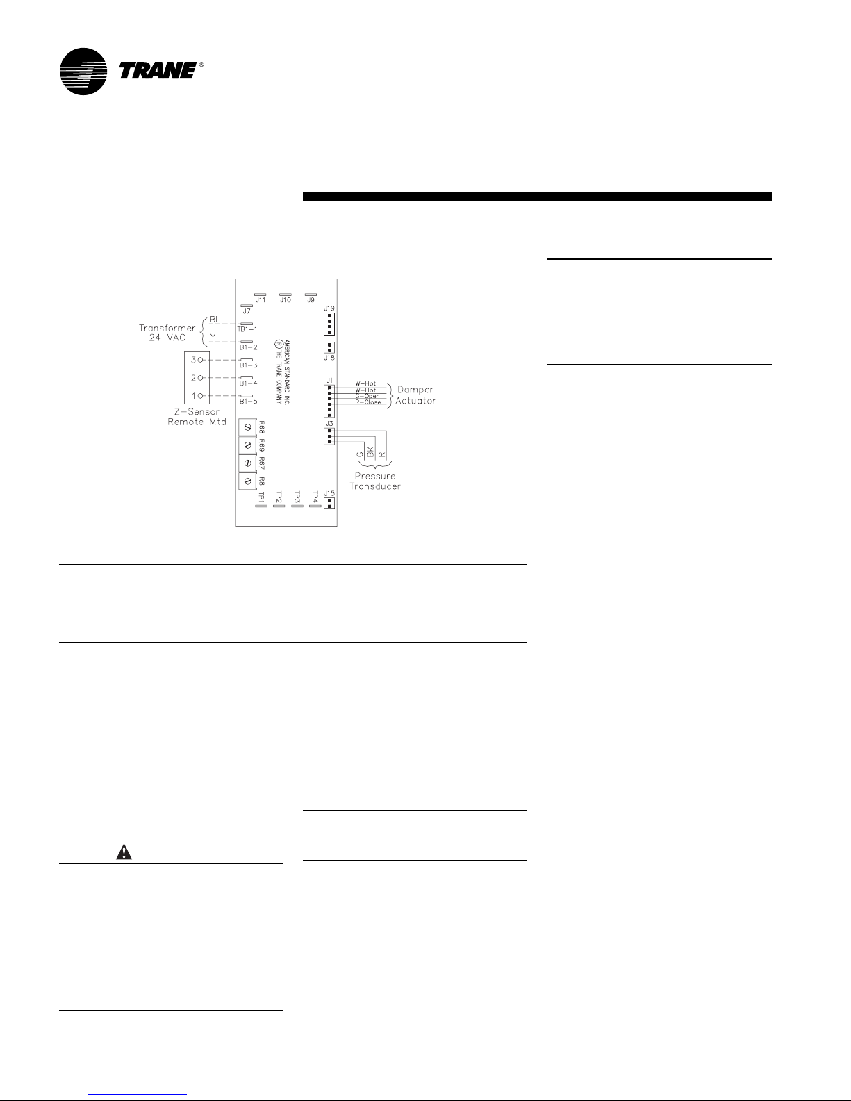
Electronic Controls Installation
Check the wiring on the unit with the wiring diagram and wiring information label.
Insure that all jumpers are to the proper location and that the actual unit wiring
matches the wiring diagram and wiring label information. See Figure 4.
Units with electronic control options must use Trane zone sensors to be compatible
with the unit circuitry. The analog zone sensor electronics are designed
specifically to operate with the Trane electronic controls; other zone
sensors will not work properly with this unit. The Trane analog zone sensor
must be used in conjunction with these electronic controls. Typically, field
controls wiring include the following:
1. 24 VAC-powered connection to terminals TB1-1 and TB1-2. These are stab terminals
marked one and two on the five-pole terminal strip located in the corner of the
circuit card.
2. Zone sensor connections are to TB1-3,4,5.
3. Heater contact wiring is normally installed in the factory. Should field installation be
required, each wiring diagram shows the field alternate wiring requirements.
VAV-SVX03A-EN 7
Page 8
Analog
Controls
Figure 4 – Typical Analog Electronic
Control Wiring Diagram
CAUTION:CAUTION:
Avoid Wiring Errors!
It is important to connect power and zone sensor control voltage wiring to the proper
terminals since improper connection will cause failure of the circuit board. To help
prevent errors, the 24 VAC power to circuit board zone sensor connections
are labeled.
Minimum and Maximum
Potentiometers Adjustments
The minimum and maximum flow (or
position) setpoints may require field
setting to obtain desired cfm settings.
Refer to the calibration section of this
manual for proper adjustment
procedures.
On single-duct boxes where transformers are optional, the transformer must
be NEC Class 2, energy-limiting, 24 VAC.
Refer to electrical data for proper sizing.
WARNINGWARNING
Hazardous Voltage!
Disconnect all electric power, including
remote disconnects before servicing.
Follow proper lockout/tagout procedures to ensure the power cannot be
inadvertently energized. Failure to
disconnect power before servicing could
result in death or serious injury. Prior to
replacing the zone sensor, follow
warning instructions above.
Zone Sensor Wiring
Each unit must be controlled by a wallor unit-mounted zone sensor which is
designed specifically for use with a
solid-state circuit board that is provided
by the factory.
Two types of zone sensors are available
with analog electronic controls. One has
the thumbwheel visible, while the other
is hidden by the cover.
NOTE: Analog electronic zone sensors
are not interchangeable with DDC
zone sensors.
The three wires required for the wall
zone sensor to the terminal block are to
be furnished and completed by
the installer.
If local codes require enclosed
conductors, the zone sensor wires
should be installed in conduit. Do not
route zone sensor wires in conduit with
24-volt or any high-powered conducting
wires. This will cause electrical noise
and result in erratic operation of
the controls.
CAUTION:CAUTION:
Circuit Board Damage!
Before handling the circuit board,
discharge any static electricity you may
have accumulated by touching the unit
casing. Static charges produce voltages
high enough to damage the electronic
components.
Location and Installation
A zone sensor in each control zone
should be located in the most critical
area of the zone. Sensors should not be
installed in direct sunlight or in the
area’s supply air stream. Subdivision of
the zone may be necessary for adequate control and comfort.
Avoid installing zone sensors in areas
subject to the following:
Drafts or “dead spots” behind doors
or corners.
Hot or cold air ducts.
Radiant heat from the sun or
appliances.
Concealed pipes or chimneys.
Unheated or uncooled surfaces behind
the sensor such as outside walls.
Air flows from adjacent zones or
other units.
8 VAV-SVX03A-EN
Page 9

Sequence of
Operation
Single-Duct Units
The air damper is controlled between
minimum and maximum flow setpoints
proportionally. When the zone temperature is approximately 0.5°F above the
setpoint, the air damper will begin to
modulate to a maximum position,
providing more cool air to the zone until
the zone temperature reaches the zone
setpoint. Once satisfied, the air damper
will start to modulate to the minimum
position. When the zone temperature is
0.5°F below the setpoint, the damper
begins to modulate to a minimum
position. When the damper is at the
cooling minimum and the zone temperature is still below setpoint (cold), up
to three stages of heat may be energized on a reheat unit. The first stage is
activated at approximately 2°F below
the setpoint, the second stage is
activated approximately 3°F below the
setpoint, and the third stage is activated
approximately 4°F below the setpoint.
Series Fan-Powered Untis
The series fan-powered unit is a
constant volume, variable temperature
device. The fan is energized whenever
the zone is occupied. It delivers design
cfm regardless of the load. The air
damper controls primary air proportionally between minimum and
maximum flow setpoints. When the
zone temperature is approximately
0.5°F above setpoint, the air damper
will begin to modulate to a maximum
position, providing more cool air and
less plenum air to the zone until the
zone temperature reaches the zone
setpoint. When zone temperature is
0.5°F below the setpoint, the damper
begins to modulate to its minimum
position, supplying less cold air and
more warm plenum air. When the air
damper is at minimum and zone
temperature is still below setpoint
(cold), up to two additional stages of
electric heat may be energized. On an
electric reheat unit, the first stage is
activated approximately 2°F below the
setpoint. The second stage is activated
approximately 3°F below the setpoint.
On Hot Water Reheat just one stage of
heat, in addition to the fan, will be
activated approximately 2°F below
the setpoint.
Parallel Fan-Powered Units
The parallel fan-powered unit is a
variable-volume, constant-temperature
device at high cooling loads and a
constant-volume, variable-temperature
device at low cooling and heating loads.
The air damper controls primary air
proportionally between minimum and
maximum flow setpoints. When the
zone temperature is approximately
0.5°F above setpoint, the air damper
will begin to modulate to a maximum
position, providing more cool air and
less plenum air to the zone until the
zone temperature reaches the zone
setpoint. When the zone temperature is
approximately 0.5°F below the setpoint,
the damper will begin to modulate to a
minimum position, reducing the cooling
capacity. If the cooling capacity is
reduced and zone temperature is still
below the heating setpoint, the fan will
be energized at approximately 2°F
below the cooling setpoint acting as the
first stage of heat. The second stage of
heat (electric or hot water) is activated
at approximately 3°F below the cooling
setpoint and the third stage (electric) is
activated at approximately 4°F below
the cooling setpoint.
VAV-SVX03A-EN 9
Page 10
Control
Options
CONTROL OPTIONS
Constant Volume
With this feature, when jack J15 Pin A is
connected to Pin B, the electronics will
cause the airflow to go to the maximum
setting and stay there. The influence of
the thermostat is removed and maximum flow is maintained at all times.
The operation of the three reheat relays
is unaffected. Connecting Pins A and B
of jack J15 will only affect the signal
which goes into the section of the
electronics which controls the air
damper movement. The maximum
flow option is obtained by saturating the
temperature voltage signal so that the
maximum limit is always sent on to the
section of the electronics, which
compares the temperature voltage to
the flow voltage.
Auto Dual Minimum
The auto dual minimum enables the
unit to change the minimum automatically without an outside signal. The
minimum changes when the first stage
relay is activated. The electronics have
been designed so that when jack J18
Pins A and B are connected together,
Minimum B (Potentiometer R69) will
control whenever the first relay stage
activated. Therefore, no matter what
minimum was in control before the
relay stage was activated, after being
activated, Minimum B (R69) will be the
determining minimum flow. This option
can be used effectively with fanpowered units where a minimum flow
is set as the damper modulates and
when the first stage comes on, the air
damper is then closed. In this manner,
airflow to the space is never interrupted; however, the energy associated
with maintaining a minimum air
damper airflow at all times is saved.
10 VAV-SVX03A-EN
Page 11
Calibration
The following tools are required to
properly adjust and calibrate the
electronic controls:
Digital voltmeter
0-2 in. wg magnehelic gage (or inclined
manometer)
Tubing and fitting to connect gage to
flow ring tees (5/32" and 1/4" tubing).
Mechanical tools (screwdriver,
pliers, etc.)
WARNINGWARNING
Hazardous Voltage!
Certain tests or calibration procedures
described in this section may involve
working in close proximity to live
electrical terminals. Only qualified and
licensed electrician or other properly
trained in electrical safety when
working with live voltage should
perform these procedures. Failure to
follow all electrical safety precautions
when exposed to live terminal could
result in death or serious injury.
Transducer Operation
This section discusses how airflow
through the damper is transformed into
a voltage signal that can be used by the
controller. The first transition from flow
to voltage occurs at the Trane flow ring,
where a delta P signal is generated as a
function of airflow through the unit. The
delta P signal consists of a highpressure signal from a total-pressure
tap of the airflow ring and a lowpressure signal from the wakepressure side of the flow ring.
The transducer converts the pressure
differential signal to an output voltage.
The output of the transducer with no
flow or zero delta P is .250 volts DC
(+ .100). As flow increases, the delta P
signal increases; therefore, the output
voltage of the transducer increases. The
gain of the transducer is 0.75 volts per
inch of delta P.
Null Voltage
The tolerance for the output voltage of
the transducer with zero delta P signal
from the flow ring is referred to as the
null voltage of the transducer. The
transducer has three wires leading
from it to the control board. The wires
include a common (green wire), an
input (red wire), and an output (black
wire). The input (supply) voltage to the
transducer is 5 volts (+ .5). The acceptable voltage range of the output voltage
with zero flow (between black and
green) can range from .100 volts to .400
volts. To allow the controllers to
coordinate with the transducer voltage,
internal calibration is necessary. To
accomplish this, potentiometer R8 (zero
flow adjustment) is used. The flow
voltage signal should be 4.8 volts at test
points #1 and #3 of the test point
terminals (next to R8) with zero delta P
applied. R8 is used to adjust the flow
voltage to 4.8 volts when zero delta P is
applied to the transducer. In this
manner, variability of the null point of
the transducer is compensated for. The
importance of this becomes evident
when minimum and maximum flows
are discussed.
PROCEDURE FOR
MAXIMUM AND MINIMUM
CALIBRATION
Initialization
1. Monitor thermostat voltage and check
it by rotating the thermostat to full
heating and full cooling.
a. Connect a voltmeter to TB1-4 (+)
and TB1-3 (-).
b. Rotate the thermostat fully
clockwise (full heating). Observe
the voltage. It should be less
than or equal to 5.4 volts DC.
c. Rotate the thermostat fully
counter-clockwise (full cooling);
voltage should go up to 6.3 volts
DC or greater.
2. Set the min/max pots as follows:
a. Rotate the max pot (R67) full
clockwise.
b. Rotate min A (R68) full counter-
clockwise
c. Rotate min B (R69) full counter-
clockwise
3. With both of the transducer ports open
to ambient (0 delta P), read the output
voltage at TP4. (Ground is either TP3,
TB1-2, or TB1-3.) The value of the null
transducer voltage output must be
between 0.1 and 0.4 volts DC.
Nominal is .250 volts DC.
4. Monitor TP1 (+) voltage (zero flow
adjustment) and adjust R8 until 4.8
volts DC + .010 volts is read at TP1.
Set Maximum Flow
Set the thermostat knob to the full-cool
position (fully counter-clockwise)
thermostat voltage should go over 6.2V
DC. Connect a pressure gage teed into
the high- and low-port flow ring of the
transducer and input the maximum
delta P. Refer to the flow vs. delta P chart
on the unit to obtain the proper delta P
signal desired. Adjust the max pot (R67)
so that both the amber and green lights
are out, this indicates that equilibrium
has been established with the delta P
input to the transducer.
VAV-SVX03A-EN 11
Page 12

Calibration
Set Minimum Flow(s)
In this section, two procedures for
setting minimums will be discussed.
No Dual Minimum
Adjust the thermostat knob to the fullheat position (full clockwise). Monitor
the delta P of the transducer with a
pressure gage (high port first and low
port). Refer to the calibration label on
the side of the unit, which relates CFM
to delta P. Adjust R68 (minimum A) so
that both the red and green lights are
out at the desired minimum flow delta P.
If the minimum setting is to be zero flow,
then leave the minimum pot (R68) full
counter-clockwise so that the red light
remains on even when no delta P is
applied to the transducer. This will
ensure that the unit will always go to
closed when minimum is desired.
Auto Dual Minimum
Place jumper on J18-A to B.
The heating minimum is the minimum
at which the damper is controlled to
when the fan on a fan-powered unit is
activated or when the first relay is
activated on a reheat unit.
Set the thermostat to the full-heat
position (full clockwise).
Adjust minimum potentiometer R69
(Minimum B) to desired heating
minimum. If this setting is to be zero,
leave the potentiometer fully counter-
clockwise so that the amber light
remains on with no delta P applied to
the transducer.
Remove the jumper from J18-A to J18B. This puts the unit into the mode
where minimum A is now in control
(cooling minimum).
Adjust R68 (Minimum A) when both
lights are off when the condition is
satisfactory. If zero minimum is desired,
leave pot R68 full counter-clockwise so
that the amber light is on continuously
with zero delta P applied to the
transducer.
Replace J18 jumper.
12 VAV-SVX03A-EN
Page 13

Balancing
The following tools are required to
properly adjust and calibrate the
electronic controls:
Digital voltmeter
0 to 2 in. wg magnehelic gage
Tubing and fitting to connect gage to
flow ring tees.
Mechanical tools i.e. screwdriver,
pliers, etc.
Balancing Procedure
1. Check the 24-volts AC supply voltage
to the circuit card, terminals TB1-1 to
TB1-2. Acceptable range =
21.6 to 26.4 volts AC.
2. Check the 12-volts DC power supply of
the circuit card terminals TB1-5 (+) to
TB1-3 (-). Acceptable range = 11.6 to
12.4 volts DC.
3. Install the magnehelic gage to
observe delta P. When connecting to
the test tees, be careful not to create
an excessively low pressure on the
transducer (when used). The following
procedure should be followed:
a. Remove low-pressure cap from
test tee.
b. Remove high-pressure cap
from test tee.
c. Connect gage to high-
pressure side.
d. Connect gage to low-
pressure side.
Adjustments (Set Maximum and
Minimum Flows)
To set minimum and maximum flows to
the desired setting, refer to the
calibration section.
VAV-SVX03A-EN 13
Page 14

Installation
and Wiring
The general layout of the analog circuit
board is shown in Figure 5. The layout of
the circuit card shows the physical
location of each item. Basic connections
are as follows (see Figure 4, page 7):
Figure 5 – Analog Electronic Controller
1. Power is connected to TB1-1 and TB1-
2. The power requirement is 24 volts
AC (+ 10%).
2. The zone sensor is connected to
terminals TB1-3, 4, and 5. It is very
important not to connect power to
these terminals, since applying power
to the wrong terminal will destroy the
card.
3. The motor is connected via jack J1.
4. The transducer (pressureindependent) is connected at jack J3.
5. Reheat stages (or fan on fan-powered
units) are connected at jacks J7 (24
VAC), J9, J10, and J11.
6. Various options to cause changes to
the operation of unit are input at
jack J15.
7. There are various adjustments on the
circuit card as discussed in detail in the
Calibration section.
a. Maximum flow (or position)
adjustment is R67. Turning
clockwise increases the
maximum flow.
b. There are two minimum flow
adjustments labeled R68 and
R69. Turning clockwise
increases the minimum flow.
c. There is a zero-flow adjustment
used in initial calibration and setup of the circuit card. This is R8.
8. There are four test points for the
convenience of servicing in the field.
These test points include:
TP4: Transducer output
TP1: Flow voltage (null calibration)
TP2: Temperature voltage
TP3: A common to make application of
clip leads easy.
14 VAV-SVX03A-EN
Page 15

Zone
Sensor
Zone Sensor Operation
This section explains how the zone
sensor operates.
Temperature is sensed using a
thermistor. The thermistor changes
resistance with a change in
temperature. The resistance of a
thermistor decreases as temperature
increases. By using a voltage divider
circuit, the deviation from the room
setpoint is determined.
1. 12-volts DC is supplied from TB1-5 on
the circuit card to terminal 1 on the
zone sensor.
2. The zone sensor output signal is
connected from terminal 2 of the zone
sensor to TB1-4 on the circuit card.
3. A common (ground) is supplied from
TB1-3 on the circuit card to terminal 3
on the zone sensor. At setpoint, the
input to the circuit card is 6 volts
measured across terminals 2 and 3.
Therefore, with 12 volts input between
terminals 1 and 3, the voltage drop
across the thermistor will equal the
voltage drop between terminal 2 and
terminal 3. With the voltages being equal, the room temperature is considered
satisfied and all output relays are de-energized. If the temperature in the zone goes
up, the resistance of the thermistor will go down, causing a voltage increase, which
will drive the air damper open. Conversely, if the room temperature goes down, the
thermistor resistance goes up, causing a decrease in the output signal, which will
drive the air damper to minimum and energize the relay output. To determine the
setpoint, the setpoint potentiometer is moved, changing the resistance between
terminals 2 and 3. By changing the setpoint potentiometer, the temperature at which
the output signal equals 6 volts will be changed. Therefore, the setpoint potentiometer
moves the setpoint up and down.
Degrees Fahrenheit Thermistor Nominal Resistance (Ohms)
65 4070
66 3960
67 3850
68 3750
69 3660
70 3580
71 3500
72 3420
73 3330
74 3250
75 3170
76 3080
77 3000
78 2940
79 2870
80 2810
VAV-SVX03A-EN 15
Page 16

Troubleshooting
Symptom Probable Cause Recommended Action
Fan not running Faulty connection Check wiring diagrams and inspect all connections.
Incorrect voltage input Compare actual voltage with supply requirement.
Fan motor noise Incorrect voltage input Compare actual voltage input with supply requirement.
Low cfm to unit Supply fan not providing Adjust supply fan speed. Check for proper rotation.
Improper cfm to zone Debris is jamming valve Clear valve damper travel.
Incorrect air temperature Incorrect wiring to reheat coil Check and replace if necessary. Compare wiring with diagram on unit.
delivered to the zone
Coils do not engage on Faulty relay or Triac Check for voltage to heating coil and relay(s). Verify supply voltage matches coil voltage.
Call for heat
Room temperature differs Erratic zone sensor Check zone sensor voltage 12-volts DC between terminals 1 and 3. Check DC voltage at zone sensor
from reading on zone terminal 2 and 3 (6 volts DC). Turn zone sensor to full heating voltage; it should be equal to or less
Sensor (PI) than 5.4 volts DC. Turn zone sensor to full cooling voltage should be equal to or greater than 6.5 volts
Faulty fan motor Check motor and power to the fan motor. If power is present and fan does not run, replace the motor.
Loose fan wheel Adjust and tighten fan wheel
adequate cfm
Leaky duct work Repair leak.
Dirty Filters Replace air filters
Damage to valve casing Repair casing or replace valve.
Improper wiring Check unit diagrams for correct connection.
Faulty circuit board Check and replace if necessary.
Faulty valve motor Check and replace if necessary.
cfm setting incorrect Recalibrate circuit board.
Faulty zone sensor Check for correct zone sensor resistance.
Faulty circuit board Recalibrate and replace if necessary.
Incorrect supply air temperature Check leaving air temperature from air handling unit.
Board not calibrated Calibrate.
DC. If DC voltage is not attainable, replace the zone sensor.
Zone sensor miscalibrated. Check calibration of zone sensor. See also calibration section.
Tools and Equipment
When repairing a VariTrane product (analog control), it is important to have the necessary tools and instruments.
1. 0-2" magnehelic gauge with fittings for two ¼" outside diameter (OD) tubing
2. Voltmeter
3. Four jumper leads
4. Small screwdriver 1/8" blade
Hazardous Voltage!
Certain tests or calibration procedures described in this section may involve working in close proximity to live electrical terminals.
Only qualified and licensed electrician or other properly trained in electrical safety when working with live voltage should
perform these procedures. Failure to follow all electrical safety precautions when exposed to live terminal could result in death
or serious injury.
16 VAV-SVX03A-EN
WARNINGWARNING
Page 17

Troubleshooting
System Check
Improper room control may be caused
by areas other than the VAV boxes.
Before replacing the air damper or
control box, make sure that the entire
system is operating properly and is
supplying sufficient air to the damper.
Complete the following checks.
1. Look for obvious leaks in the duct
system. Assure that sufficient static
pressure is present at the air
Damper.
2. Inspect the supply fan and VAV fan
filters. Clean or replace, if necessary.
3. Check zone sensor location, outside
wall, appliances, direct sunlight or the
supply air stream may be artificially
heating or cooling the zone sensor.
4. Evaluate diffuser should have 15" of
flat ceiling surface on either side of the
slot to assure proper air distribution.
Check that airflow from grills or
diffusers is properly balanced.
5. For accurate flow control, there must
be at least two duct diameters of
straight ductwork before the air
damper inlet. Electric coils require four
feet of straight ductwork downstream
of the coil.
6. Compare voltage requirements, as
specified on the side of unit with actual
voltage supplied to the unit. The
control voltage requirement is
24-volts AC + 10%.
Air Damper and Motor Check
If problems occur with damper actuation, perform the following steps:
1. Visually inspect the damper for loose
gaskets, casing damage, or restriction
to damper travel.
WARNINGWARNING
Hazardous Voltage!
Certain tests or calibration procedures
described in this section may involve
working in close proximity to live
electrical terminals. Only qualified and
licensed electrician or other properly
trained in electrical safety when
working with live voltage should
perform these procedures. Failure to
follow all electrical safety precautions
when exposed to live terminal could
result in death or serious injury.
2. Be sure that there is proper voltage
supplied by checking for 24 volts at
terminal 1 and 2 on the circuit board.
Acceptable voltage range is 21.6 to
26.4-volts AC.
3. To open the damper, apply 24-volts AC
to the white and green wires on the
motor plug coming from the actuator.
The drive takes a maximum of 90
seconds to fully open.
4. To close the damper, apply 24-volts AC
to the white and red wires on the
motor plug coming from the actuator.
5. If the motor fails to operate from a
direct 24-volts AC power source, and
there is neither binding nor
obstructions, then the actuator is
defective and should be replaced.
Control Check
WARNINGWARNING
Hazardous Voltage!
Disconnect all electric power, including
remote disconnects before servicing.
Follow proper lockout/tagout procedures
to ensure the power cannot be inadvertently energized. Failure to disconnect
power before servicing could result in
death or serious injury.
1. Disconnect power source and remove
zone sensor wires 3, 4, and 5. Be sure
to mark the wires so that they will be
correctly replaced.
2. Reconnect power to the unit. The
damper should move to its minimum
or fully closed position.
3. Jumper terminals 4 and 5. The green
LED should light. This should cause the
damper to move fully open or to its
maximum flow setting.
4. Disconnect the jumper from terminals
4 and 5.
5. Jumper terminals 3 and 4. The amber
LED should light. The damper should
close to minimum and the relays (or
reheat) should energize.
6. Remove Jumper terminals 3 and 4.
7. If everything operates correctly,
disconnect power and reconnect all
wires. Check the air damper or zone
sensor for further trouble analysis.
Zone Sensor Check
To troubleshoot the zone sensor, make
sure that 24 volts are available at the
control unit board and then complete
the following procedure:
1. Move the zone sensor to full cooling.
The damper should open completely.
If the action is reverse, check the
proper zone sensor connection.
2. Rotate the zone sensor knob to full
heat. This should cause the damper to
close and fan to come on. When the
room setpoint is above the actual
room temperature, stages of heat will
be energized, if enabled.
3. If the zone sensor does not operate at
all, check the wiring from the board to
the sensor. Reference the zone
sensor section.
4. Check DC voltage at zone sensor
terminals 2 and 3 (6-volts DC). Turn
the zone sensor to full heating voltage;
it should be equal to or less than
5.4-volts DC. Turn the zone sensor to
full cooling; voltage should be equal to
or greater than 6.5-volts DC.
Heater Contactor Check
To troubleshoot heater contacts on units
with electric reheat, complete the
following procedure:
1. Disconnect power source.
WARNINGWARNING
Hazardous Voltage!
Disconnect all electric power, including
remote disconnects before servicing.
Follow proper lockout/tagout procedures
to ensure the power cannot be inadvertently energized. Failure to disconnect
power before servicing could result in
death or serious injury.
2. Disconnect wires from the contactor.
3. Connect an ohmmeter to the contacts.
4. Apply 24 volts (from independent
power supply) to the coil of relays.
Check for contact closure. If the
contact does not close, replace
the contactors.
VAV-SVX03A-EN 17
Page 18

Troubleshooting
Fan Motor Check
To troubleshoot the fan motor, complete
the following procedure:
1. Disconnect the power, check all wiring
diagrams provided on the unit.
2. Turn the power back on. Operate the
zone sensor to see if the proper
voltage is being supplied to the motor
relay. If the motor does not start, check
the capacitor and fan motor.
3. Check the motor relay by attaching a
voltmeter across the 24-volt coil of the
relay. For parallel fan-powered,
operate the zone sensor to energize
the fan and confirm the voltage to the
relay is turned on. Check for supply
voltage between the common and hot
side of the relay.
4. Attach a Voltmeter to the white
common wire on the terminal block
and the blue, black or red wires from
the fan motor. If line voltage is present,
check for fan obstruction.
5. With the power off, spin the fan wheel.
If it does not run freely, check shaft
alignment or housing clearances.
Circuit Board Check
1. Remove the control box cover. Inspect
all wiring and compare with the label
on the control box cover. The label
also indicates jumper connections.
Make sure that all wiring and jumpers
are connected exactly as shown on
the diagram.
2. Measure the voltage a terminals
TB1 –1 (+) and TB1 –2 (-) on the circuit
board. The voltage reading should be
24-volts AC +/- 10%.
3. Measure the voltage at terminal TB1-5
(+) and TB1-3 (-) on the circuit board.
Voltage reading should be 12-volts
DC + 10% tolerance. This voltage is
the output power for the zone sensor.
If these voltage readings are not
shown, it could indicate a
defective board.
4. If 12-volts DC is present, rotate the
zone sensor thumbwheel and check
for voltage change across zone sensor
terminals 2 and 3.
5. Adjust the minimum fully counterclockwise and the maximum
fully clockwise.
6. Verify the amber and green lights
change when rotating the
thumbwheel.
7. If any step does not work,
replacement of the board may be
necessary. If all steps work, proceed
with further component checks.
Transducer Check
1. Disconnect the tubing to the flow
sensor, remove the low-pressure line
first, then the high side. Transducer
damage may result if procedure is
not followed.
2. Attach the voltmeter to terminals TP4
(+) and ground, B1-2 or 3, or TP3.
Voltage on these terminals should be
between .1- to .4-volts DC; the ideal is
.254 volts DC.
WARNINGWARNING
Hazardous Voltage!
Disconnect all electric power, including
remote disconnects before servicing.
Follow proper lockout/tagout procedures
to ensure the power cannot be inadvertently energized. Failure to disconnect
power before servicing could result in
death or serious injury.
3. Connect the voltmeter to terminals
TP1 (+) and ground. Voltage at these
terminals should be 4.78 to 4.82 volts
DC. If the voltage at these terminals is
lower or greater than the specified
tolerance, this could be the cause for
not obtaining correct minimum or
maximum flow. This causes the
controller to not operate within the
specified minimum and maximum
values, even with the minimum
potentiometer fully counter-clockwise.
Adjust R8 for 4.8 volts DC.
4. Reconnect the air valve actuator and
drive to maximum position. Voltage
should increase on TP4 to TP3.
5. If voltage does not increase, verify
with a magnehelic that the delta P
is increasing.
6. Replace the transducer if delta P
increases and voltage does
not change.
Note: A faulty transducer will cause the
air damper to function improperly.
Triac Output Check
1. Make sure that the zone sensor
operation is correct and, if applicable,
which zone sensor is under control.
Refer to prior sections for step-by-step
procedures.
2. Remove all connections from J9, J10,
and J11. In addition, remove J19 if it is
a series fan-power unit.
3. Set the zone sensor to the full
cooling position.
4. Place a 500-1000 ohm resistor
between the connectors J7 and J9
and measure the voltage between
these points. It should be less than 10
volts AC.
5. Slowly increase the zone sensor
setting from full cooling to heating. At a
position on the zone sensor near room
temperature, Triac #1, which connects
J7 to J9 should close. Next, Triac 2,
which connects J7 to J10, should
energize and finally Triac 3, which
connects J7 to J11, should energize.
When the zone sensor is rotated to the
full heating position, a voltage check
should show that contact closures
between J7 and J9, J7 and J10, and
J7 and J11 have been made (closed).
6. If continuity is not present at all stages,
replace the board.
Auto Dual Minimum Check
A digital voltmeter will be required to
make the voltage checks described in
this procedure. Note the following
differences in labeling of adjustment
potentiometer described in the following steps:
Circuit
Board
Label
R8 Null Voltage Calibration
R67 Max Flow
R68 Min Flow A
R69 Min Flow B
1. Refer to calibration setup steps 1
through 4. Make changes as described
in the following steps:
2. Rotate the zone sensor to the full cool
position. The green LED should be
illuminated on the circuit board and
voltage present at terminals J1-3 to
J1-1. The voltage at terminal TP2 to
ground should be 5.9 volts DC
or higher.
18 VAV-SVX03A-EN
Page 19

Troubleshooting
3. Slowly rotate the zone sensor until the
amber LED on the circuit board
illuminates. Voltage at terminal TP2 to
ground should be approximately
3.2 volts DC.
4. Continue rotating the zone sensor until
the first stage of heat energizes. This
can be determined by voltage across
terminals J7 to J9. At this point, the
green LED on the circuit board should
illuminate. Voltage at terminal TP2 to
ground should be 3.9 volts DC or
higher. R68 should be in control.
5. Now adjust the zone sensor so that the
output voltage at terminals 2 and 3 is
6.0 volts DC, +.01 volts DC, -.01
volts DC.
6. Compare the actual zone sensor to the
indicated setpoint on the dial of the
zone sensor. If the two readings are
within 3°F of each other, then the zone
sensor is within standard calibration
tolerance. Calibration procedures are
described in the Calibration Section in
this manual.
7. Note position of R69. Rotate
potentiometer R69 clockwise and
counter-clockwise while watching the
amber and green LED’s to make sure
that the control is now with minimum
potentiometer R69.
8. Return R69 to its original position.
Electronic Zone Sensor
Check
Note: The following checkout procedures
will be used when power is applied to
the electronic zone sensor.
1. Room temperature must be between
65°F and 80°F. Make sure also that
placement of the zone sensor is
satisfactory. It should not be located in
direct sunlight, on cold or hot wall
surfaces, etc. A zone sensor or other
accurate temperature measuring
device should be installed next to the
zone sensor. It is preferable to mount
the temperature sensing element
under the zone sensor cover next to
the thermistor of the zone sensor. (the
Thermistor is a small electronic
temperature sensing device
imbedded in a glob of silicone
cement.)
2. Remove the zone sensor cover.
3. Attach a volt meter to terminals 2 (+)
and terminal 3 (-).
4. Record temperature in zone. It should
be between 65°F and 80°F.
5. Check the voltage a terminals 2 (+)
and terminal 3 (-). If the zone
temperature and the zone sensor
setpoint are at equilibrium, the voltage
at this point should be 6.00-volts DC.
6. Rotate the zone sensor to the fullheating position. Allow five minutes for
the zone sensor to equalize setpoint.
The voltage on terminals 2 and 3
should drop to 5.5-volts DC or less.
7. Rotate the zone sensor to the full
cooling position. The voltage on
terminals 2 and 3 should rise to
6.3-volts DC or higher.
Jack Numbering Designations
for Analog Control Boards
Jack Function
J1 Motor
J3 Transducer
J9 Stage 1 Contact
J10 Stage 2 Contact
J11 Stage 3 Contact
J15 Drive MAX (constant volume)
J18 Auto Dual Minimum
J19 Output Override
TB1 Field Connections: Power and Zone
Sensor
VAV-SVX03A-EN 19
Page 20

The Trane Company
An American Standard Company
www.trane.com
For more information contact
your local district office of
e-mail us at comfort@trane.com
Literature Order Number VAV-SVX03A-EN
File Number SL-TD-VAV-000-SBX03A-EN-1101
Supersedes New
Stocking Location La Crosse
Since The Trane Company has a policy of continuous product and product data improvement, it reserves the right
to change design specifications without notice.
Only qualified technicians should perform the installation and servicing of equipment referred to in this
publication.
 Loading...