

Page 1
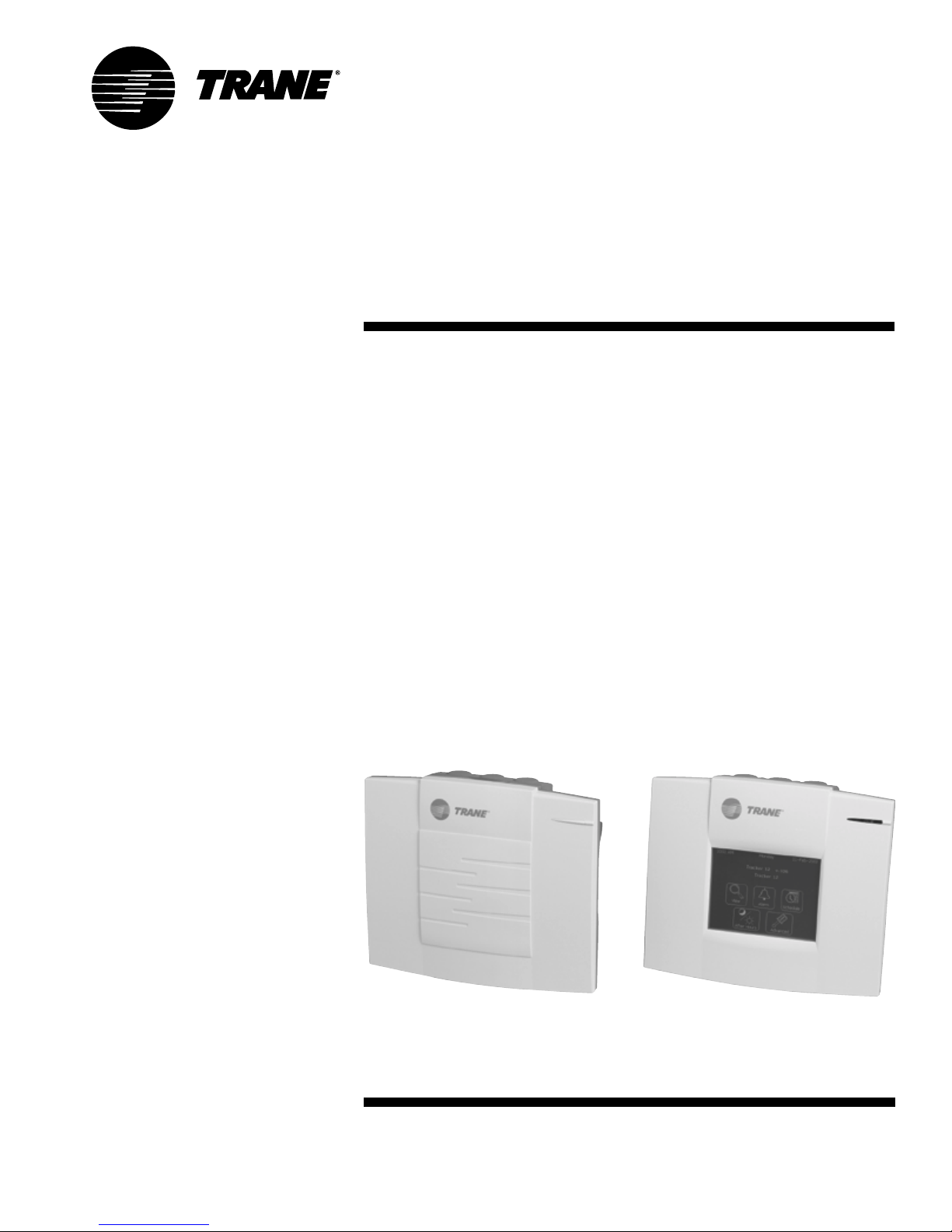
Controller
Operator Guide
VariTrac
Central Control Panel
TM
VAV-SVU01A-EN
Page 2

VariTrac Central Control Panel Operation Guide
This guide and the information in it are the property of American Standard
Inc. and shall not be used or reproduced in whole or in part, except as
intended, without the written permission of American Standard Inc. Since
Trane has a policy of continuous product improvement, it reserves the right
to change design and specification without notice.
Use of the software contained in this package is provided under a software
license agreement. Unauthorized use of the software or related materials
discussed in this manual can result in civil damages and criminal penalties.
The terms of this license are included with the compact disc. Please read
them thoroughly.
Trane has tested the system described in this manual. However, Trane does
not guarantee that the system contains no errors.
Trane reserves the right to revise this publication at any time and to make
changes to its content without obligation to notify any person of such
revision or change.
Trane may have patents or pending patent applications covering items in
this publication. By providing this document, Trane does not imply giving
license to these patents.
The following are trademarks or registered trademarks of Trane: Comfort
Manager, Reliatel, Tracker, Trane, VariTrac, VariTrane, and Voyager.
Windows is a registered trademark of Microsoft Corporation.
Printed in the U.S.A.
© 2002 American Standard Inc. All rights reserved.
VAV-SVU01A-EN
Page 3

Contents
Chapter 1
Chapter 2
Chapter 3
About This Guide .................................................. 1
VariTrac CCP Naming Conventions ...............................................................1
Cautionary Statements ..................................................................................2
Related Literature ...........................................................................................2
VariTrac History .................................................... 3
Feature Summary ................................................. 5
New Features.................................................................................................. 5
Functional Enhancements .............................................................................6
Increased Zone Count.............................................................................. 6
Discharge Air Control...............................................................................6
Supply Air Tempering............................................................................... 6
Feature Summary .................................................................................... 6
CO2 Based Demand Control Ventilation..................................................6
Zone Occupied Standby Function .......................................................... 6
System Balance Mode .............................................................................6
VAV-SVU01A-EN
Chapter 4
Chapter 5
Global Sensor Setpoint Limit Set-up ......................................................6
Software Change History ..................................... 7
General Information ............................................. 9
Central Control Panel ..................................................................................... 9
Communicating Sensor–Bypass Control Assembly..................................... 9
Bypass Damper(s) ........................................................................................ 10
Zone Damper with a UCM and Zone Temperature Sensor ........................ 10
i
Page 4

Table of Contents
Chapter 6
Sequence of Operation....................................... 11
Central Control Panel ................................................................................... 11
CCP Start-up ........................................................................................... 11
Bypass System Calibration ................................................................... 11
Static Pressure Bypass ..........................................................................12
Heat/Cool Mode Decision for Zones .....................................................12
Zone Voting for System Heat or Cool ................................................... 13
UCM Zone Tagging for No Vote .............................................................13
Zone Heat/Cool Call Strength ................................................................ 14
Heat/Cool Decision for the CCP ............................................................. 14
Heat/Cool Changeover for the CCP ....................................................... 15
Heat/Cool Changeover from Opposite Strong Callers ......................... 15
Heat/Cool Staging and Discharge Air Control ...................................... 15
Morning Warm-Up/Precool Mode .........................................................16
Manual Heat/Cool Mode Control ..........................................................16
Priority Shutdown.................................................................................. 17
Voyager/Reliatel Rooftop Operation versus Binary Output Control ... 17
2 Heat/2 Cool versus Heat Pump Operation ......................................... 18
Spare Binary Output Control ................................................................. 18
Auxiliary Heat Lockout........................................................................... 18
Occupied Priority Local Heat ................................................................. 18
Unoccupied Priority Local Heat............................................................. 19
Unoccupied Control ............................................................................... 19
VariTrac CCP Group Functions ..............................................................20
Group Occupied/Unoccupied ........................................................ 20
Timed Override ...............................................................................21
Group Overrides .............................................................................21
System Balance Mode ...........................................................................22
CO2 -Based Demand Control Ventilation............................................... 22
Global Sensor Setpoint Limit Setup ..................................................... 23
ii
VAV-SVU01A-EN
Page 5

Chapter 6
cont’d
Unit Control Module (UCM)......................................................................... 23
UCM Start-Up......................................................................................... 23
Setpoints ................................................................................................ 24
Parameters ............................................................................................. 25
Damper Control......................................................................................25
Heat/Cool Mode Decision for Zones .....................................................26
Local Heat Control ............................................................................. 26
Priority Local Heat .................................................................................. 27
Stand-alone Control............................................................................... 27
UCM CO2 Input for VariTrac Demand-Controlled Ventilation .............. 28
Occupied/Unoccupied Mode................................................................. 29
UCM Zone Occupied Standby Function ...............................................29
Drive to Maximum ................................................................................. 29
Override to Unoccupied ........................................................................ 30
Failure Modes.........................................................................................30
UCM Interface ........................................................................................ 30
Zone Sensor Operations ..............................................................................31
Zone Temperature .................................................................................. 31
Zone Setpoint Control ...........................................................................31
Timed Override and Cancel...................................................................31
Modem Interface for Remote Communications ......................................... 32
Modem Requirements for the VariTrac CCP .........................................32
Configuring the External Modem ......................................................... 32
Connecting the Modem to the VariTrac CCP ........................................ 32
Modem Operation.................................................................................. 33
VariTrac CCP Interface ..................................................................................33
CCP Operator Display ............................................................................33
VariTrac PC Software..............................................................................33
Tracker Version 10 Panel ........................................................................ 33
VAV-SVU01A-EN
iii
Page 6

Table of Contents
Chapter 7
Delivered VAV Operation .................................... 35
What “Delivered VAV” Is ..............................................................................35
What “Delivered VAV” Is Not ....................................................................... 35
System Operating Overview ........................................................................ 36
Zone Count ............................................................................................. 36
Automatic Configuration and Start-up .................................................36
Morning Warm-Up .................................................................................36
Supply Air Temperature Control ............................................................ 36
Supply Air Setpoint Reset...................................................................... 37
Daytime Warm-Up.................................................................................. 37
Unoccupied Control ............................................................................... 37
Supply Air Pressure Control .................................................................. 38
Supply Air Pressure Limiting................................................................. 38
Fan Pressure Optimization .................................................................... 38
Power Exhaust Control ..........................................................................38
CO2 -Based Demand-Controlled Ventilation .........................................39
Chapter 8
System Calibration................................................................................. 39
Zone Occupied Standby Function ........................................................ 39
Global Sensor Setpoint Limit Setup ..................................................... 40
System Balance Mode ...........................................................................40
Using the Operator Display ................................ 41
Overview .......................................................................................................41
Screen Layout............................................................................................... 42
Title Bar .................................................................................................. 42
Navigation Buttons ................................................................................ 42
Selection Buttons ...................................................................................42
Home Screen ................................................................................................44
Operation Screens........................................................................................ 45
Branch Selection Screen........................................................................ 45
iv
VAV-SVU01A-EN
Page 7

Chapter 8
cont’d
Data Display Screens ...................................................................................46
Data Entry Screens ....................................................................................... 46
Analog Data Entry Screen ..................................................................... 47
Alphanumeric Data Entry Screen.......................................................... 48
Confirmation Screens ..................................................................................49
View Procedures ........................................................................................... 51
Determine Area Temperature.................................................................51
Determine Area Temperature Setting.................................................... 51
Adjust Area Temperature Setting .......................................................... 52
Determine Area Occupancy................................................................... 53
Acquire Detailed Area Occupancy Schedule Status ............................ 53
Override Area Occupancy ...................................................................... 54
Cancel Area Override ............................................................................. 54
Acquire Detailed Area Status and Setup ..............................................53
Alarm Procedures......................................................................................... 54
View VariTrac Diagnostics...................................................................... 54
Schedule Procedures.................................................................................... 61
Change Daily Schedule Name ............................................................... 61
Change Daily Schedule Start and Stop Times ......................................62
Add Member to Daily Schedule ............................................................ 64
Remove Member from Daily Schedule................................................. 65
View List of Daily Schedules and Check Occupancy............................ 66
View a Daily Schedule and Schedule Members ...................................66
View Unscheduled Members ................................................................ 67
After Hours Procedures................................................................................69
Start or Restart an Area Timed Override ............................................... 69
Start or Restart Timed Override of a Single Schedule ......................... 72
Start or Restart All Timed Override Schedules ..................................... 72
Cancel a Single Area Timed Override ................................................... 72
Cancel Timed Override of a Single Schedule ....................................... 73
Cancel Timed Override of All Schedules ...............................................73
VAV-SVU01A-EN
v
Page 8

Table of Contents
Chapter 9
Advanced Functions ........................................... 75
CCP Setup and Service................................................................................. 75
CCP Setup............................................................................................... 75
Set the Current Time ....................................................................... 76
Set the Current Date ....................................................................... 76
Set the Time Format........................................................................ 77
To Change the Units of Display ..................................................... 77
Service and Testing ................................................................................ 77
Operator Display Parameters.........................................................78
CCP Hardware and Software Functions ........................................ 80
System Setup and Status............................................................................. 83
System Setup .........................................................................................83
System Name.................................................................................. 84
HVAC Unit Type ............................................................................... 84
Control Mode ..................................................................................84
Supply Air Tempering ..................................................................... 84
Discharge Cooling Setpoint ........................................................... 84
Discharge Heating Setpoint ........................................................... 84
Minimum Opposite Callers ............................................................ 85
Minimum Opposite Strong Callers ................................................ 85
Static Pressure Setpoint Multiplier ................................................ 86
System Balance Mode .................................................................... 87
Adjust Groups for Balance Mode ..................................................88
Disabling the System Balance Mode.............................................89
Changing Limits Globally ............................................................... 89
Calibrate Now ................................................................................. 90
System Status ........................................................................................91
vi
VAV-SVU01A-EN
Page 9

Chapter 9
cont’d
Zone Setup and Status................................................................................. 96
Zone Setup .............................................................................................96
Zone Name...................................................................................... 97
Heat/Cool Vote................................................................................. 97
Use Local Setpoint ..........................................................................97
Flow Override..................................................................................97
Unoccupied Cooling Setpoint ........................................................98
Occupied Cooling Setpoint ............................................................ 98
Occupied Heating Setpoint ............................................................ 98
Unoccupied Heating Setpoint ........................................................98
Zone Sensor Setpoint Limits.......................................................... 99
Cooling High Limit.......................................................................... 99
Heating High Limit.......................................................................... 99
Cooling Low Limit ........................................................................... 99
Heating Low Limit ........................................................................... 99
Airflow Maximum Position .......................................................... 100
Airflow Cooling Minimum Position ............................................. 100
Airflow Heating Minimum Position ............................................. 100
Local Heat Minimum Position (UCM 4.0 and later) .................... 100
Occupancy Sensor Setup (UCM 4.0 and later) ........................... 101
Aux Sensor Set To (UCM 4.0 and later) ....................................... 101
Zone Status .......................................................................................... 102
Group Setup ......................................................................................... 104
Group Name ................................................................................. 105
Vent Mode ..................................................................................... 105
Flow Override................................................................................ 105
Energy Saver Mode ...................................................................... 105
View or Edit Current Group Members ......................................... 105
VAV-SVU01A-EN
vii
Page 10

Table of Contents
viii
VAV-SVU01A-EN
Page 11

Chapter 1
About This Guide
This manual describes the steps required to properly set up and operate VariTrac
changeover-bypass variable air volume (VAV) systems, delivered VAV systems,
and the VariTrac central control panel (CCP). The information in this guide
includes:
VariTrac History. A brief overview of the VariTrac product history.
Feature Summary. A summary of the new features and enhancements of
VariTrac (3).
Software Change History. A chronology of version changes to the VariTrac CCP
embedded software.
Introduction to VariTrac. General information about the VariTrac CCP.
VariTrac Operation Overview. Basic operation information covering startup,
heat/cool decisions, zone controller and zone sensor operations, and modem
interface.
Delivered VAV Operation Overview. Basic delivered VAV operation information
covering startup, heat/cool decisions, zone controller and zone sensor operations,
and modem interface.
Using the Operator Display. Information and procedures for navigating through
the operator display menus, including Home, View, Alarms, Schedules, and After
Hours.
Advanced Functions. Information for advanced users, including CCP setup and
service, system setup and status, zone setup and status, and group setup.
VariTrac CCP Naming Conventions
The use of the name “VariTrac CCP” in this manual implies the VariTrac central
control panel and the VariTrac CCP embedded system software. Where
information is unique to one model, that model is specified.
VAV-SVU01A-EN 1
Page 12

About This Guide
Cautionary Statements
The following cautionary statements signal procedures or conditions that
require particular attention. Personal safety and the proper operation of
the system depend upon the strict observance of these precautions.
WARNING
Indicates a potentially hazardous situation, which, if not avoided, could
result in serious injury or death.
CAUTION
Indicates a potentially hazardous situation, which, if not avoided, may
result in minor or moderate injury.
CAUTION
Indicates a situation in which property-damage-only accidents could occur.
It is also used to alert against unsafe practices.
IMPORTANT
Alerts installer, servicer, or operator to potential actions that could cause the
product or system to operate improperly, but will not likely result in potential for
damage.
Related Literature
The following literature is referred to or pertains to equipment referred to
in this manual.
• VariTrac CCP installation guide, VAV-SVN03A-EN
• VAV UCM installations and operations,VAV-SVX01B-EN
• Voyager service literature
• Reliatel service literature
2
VAV-SVU01A-EN
Page 13

Chapter 2
VariTrac History
With the introduction of VariTrac in 1989, Trane brought their expertise in variable
air volume (VAV) controls into the changeover-bypass zoning market.
The concept of changeover-bypass zoning brings the flexibility and comfort of VAV
systems into the light commercial unitary market, at an affordable price.
The first generation of VariTrac was a 16-zone pressure dependent system. The
zone dampers featured the same electronic zone controller Trane developed for its
VAV boxes, operating in the pressure dependent mode. The heart of the system
was the Comfort Manager™, a panel which was designed to manage the HVAC
unit, bypass damper functions, and changeover decisions. The functional concept
of this original system continues to be the backbone of today’s zoning system.
In the early 90s, two important enhancements were added to the system:
• Trane’s new Comm4 communications link for the damper controllers
• The ability to directly communicate with Trane’s new Voyager UCP electronic
rooftop unit controls
Trane introduced the second generation of VariTrac in 1995. This generation
featured the central control panel as the functional replacement for Comfort
Manager. The new panel consisted of a resin enclosure, optional relay board for
24 VAC unit control, and a move to static pressure for bypass control. Improved
changeover control was added to the operating system, and the zone damper
controls were upgraded to UCM Version 3.
Trane introduced a new generation of VariTrac controls in 2002. This generation
kept all the great features of the original VariTrac system, plus added new features
and enhancements. The enhancements were designed to make the 2002
generation of VariTrac the simplest changeover-bypass zoning system to install,
commission, and service of any light commercial controls system available today.
VAV-SVU01A-EN 3
Page 14

VariTrac History
VAV-SVU01A-EN4
Page 15

Chapter 3
Feature Summary
New Features
CCP with three-piece enclosure design and optional operator display
Quick snap-in optional relay board with easy-to-wire terminal strip
Communicating sensor assembly including a UCM 4 with integral temperature
and pressure sensor, and output to the bypass damper(s)
Bypass damper with factory-installed wiring harness for plug-in connection to
the communicating sensor assembly
Zone dampers with UCM 4 boards and:
– Zone occupancy sensor input
– Zone (carbon dioxide) CO2 sensor input
New rectangular zone dampers (sizes given in inches):
– 8×12, 8×14, 8×16
– 10×16, 10×20
– 14×18
Same Comm4 communications to the zone dampers for reliable operation and
backward compatibility
Supports Comm5 communications to the new Tracker Version 10 panel
Optional touch-screen operator display with built in 7-day time clock
Windows®-based PC software program for system interface
Digital display zone temperature sensor
Pressure-independent box capability
Local heat capability
VAV-SVP01A-EN 5
Page 16

Feature Summary
Functional Enhancements
Increased Zone Count
The new VariTrac system now supports 24 zones instead of 16. The
zones may be VariTrac dampers, or any type of VariTrane VAV box
including fan-powered boxes or boxes with factory-installed local heat.
Discharge Air Control
VariTrac now does discharge air control. When there is demand for
heating or cooling from a zone, the CCP controls the discharge air
temperature to the discharge air setpoint (default 55°F cooling, 110°F
heating), using as many stages as necessary.
Supply Air Tempering
It is now possible to enable the supply air tempering function in a
Voyager via the CCP. This allows the Voyager to cycle a stage of heat on
and off to warm up the supply air stream and better manage the load
created by increased ventilation air requirements.
CO2-Based Demand-Controlled Ventilation
CO2 sensors can now be connected to VariTrac zone UCMs. The CCP
demand control ventilation will reset the ventilation damper position for
the Voyager/Precedent unit based on the CO2 level.
Zone Occupied Standby Function
A VariTrac UCM can now have an occupancy sensor connected to it. It
can be configured to perform an occupied standby function at the zone
level during the system occupied mode.
System Balance Mode
A VariTrac system can be placed in the balance mode from the operator
display or the PC software using a single button selection. In this mode,
the CCP automatically prepares the VariTrac system for balancing by
starting the supply fan, disabling heating and cooling, closing the bypass
damper, and opening all zone dampers to their maximum position.
Global Sensor Setpoint Limit Setup
The VariTrac CCP allows you to create a single set of limits for the zone
sensor setpoint thumbwheels and broadcasts them to all the zones on
the system at one time by pushing a single button.
VAV-SVP01A-EN6
Page 17

Chapter 4
Software Change History
New software versions add capabilities and improve existing operation. Each new
software version includes the features of previous versions. Only the latest
software version is shipped in new VariTrac CCP units. Existing units may contain
a previous version.
The following information states the history of VariTrac CCP embedded software
version changes:
Version 4.0.284. Pre-release version of VariTrac (3) central control panel.
Version 4.0.290. First release of VariTrac (3) central control panel.
Version 4.1.296. Second release version of VariTrac (3) central control panel.
Corrected CCP to Voyager Commercial occupancy state sync issue when
power was cycled at the unit but not at the CCP
Corrected CCP to Voyager II slave state sync issue when power was cycled at
the unit but not at the CCP
VAV-SVU01A-EN 7
Page 18

Software Change History
VAV-SVU01A-EN8
Page 19

Chapter 5
General Information
The VariTrac comfort control system brings individual temperature control
to each comfort zone in a building while using the same single-zone airconditioning unit. VariTrac varies the flow of supply air to each zone,
providing the heating and cooling capacity required. The VariTrac
changeover-bypass VAV system includes the following components:
• VariTrac central control panel (CCP)
• Communicating sensor–bypass control assembly
• Main supply duct bypass damper(s)
• VariTrac zone dampers with unit control module (UCM) and zone
temperature sensor
Central Control Panel
The CCP provides coordination, monitoring, and diagnostics for the
VariTrac zone-control system. It is responsible for communicating with
the zone dampers to determine space heating and cooling requirements,
and selecting the mode and number of stages for the heating and cooling
unit to meet those needs.
The VariTrac CCP is designed to provide coordinated control of up to 24
VAV zones and one air-handling unit. The CCP can be controlled and
monitored from an upper level system such as a Tracker Version 10.
VariTrac can also function as a stand-alone device with its occupied/
unoccupied function initiated by the time clock built into the CCP
operator display, or by a binary input from an external time clock or other
contact closure.
Communicating Sensor–Bypass
Control Assembly
The communicating duct sensor assembly consists of a static-pressure
sensor, supply-air-temperature sensor, and communicating zone UCM
board combined into one enclosure. This device performs the following
functions:
• Measures the air pressure in the main supply duct
• Monitors the temperature of the air in the main supply duct
• Controls the position of the bypass damper
• Communicates all this information to the CCP
VAV-SVU01A-EN 9
Page 20

General Information
Bypass Damper(s)
The main supply-duct bypass damper(s) are modulated by the CCP via
the communicating sensor–bypass control assembly to maintain
consistent supply duct static pressure.
Zone Damper with UCM and
Zone Temperature Sensor
The zone damper UCM compares the space temperature to the active
setpoint to determine space requirements, and to the supply air
temperature to determine available heating or cooling. It modulates the
damper to provide the proper amount of heating or cooling air to meet
comfort conditions.
The zone UCM also provides the VariTrac CCP with information about the
current comfort conditions and heating or cooling requirements of the
space.
VAV-SVU01A-EN10
Page 21

Chapter 6
Sequence of Operation
Central Control Panel
CCP Start-up
The VariTrac CCP executes the following sequence of events on power up:
1 Reads the type of rooftop and automatically configures the panel to control
the unit.
2 Calibrates the bypass control loop. (See Bypass Control, p. 12)
3 Scans all UCMs and collects zone information.
4 Determines the system operating mode (occupied or unoccupied) and
communicates it to all zones (occupied/unoccupied mode).
5 Begins normal operation.
Bypass System Calibration
Upon power-up or a change from the occupied to the unoccupied mode, the
bypass system goes through its calibration procedure. If there are no schedules
(24-hour operation) in the CCP, the system calibrates approximately once every
seven days. During calibration the system performs the following sequence:
1 All zones perform a self-calibration function (UCM reset). This calibrates the
position of the damper blade, and also does a zero-flow pressure transducer
calibration in VariTrane VAV boxes.
2 When zone calibration is complete, all zone dampers modulate to their
maximum-open position.
3 The bypass damper modulates closed; the zero static pressure reading is
taken with the fan off.
4 The system fan turns on. After 45 seconds, the reference static pressure
reading is taken and stored.
5 The bypass damper then modulates to 50 percent, and the zones are re-
leased from their maximum position.
Note: The calibration procedure can be manually started by pushing the
Now
button available on the operator display or via PC software.
Note: During the transition from the occupied to unoccupied mode, the CCP
checks to see if calibration has been performed for any reason during the last 23
hours. If calibration has already occurred, the previously stored values are used.
Calibrate
VAV-SVU01A-EN 11
Page 22

Sequence of Operation
Static Pressure Bypass
The VariTrac CCP controls the bypass damper(s) using measured duct static
pressure. The central control panel compares the measured static pressure to the
setpoint. This setpoint is determined by taking the reference static determined
during calibration, and multiplying it by the static-pressure-setpoint multiplier
percent edited in CCP Setup.
If the measured static is
percent, the bypass damper is driven towards the closed position.
If the measured static pressure is
bypass damper is driven towards the open position.
The bypass damper remains stationary if the static pressure is in the
The deadband is the area between the static pressure setpoint and the static
pressure setpoint, minus 10 percent.
The bypass damper can be repositioned up to four times per minute. When the
bypass damper is repositioned open, it moves 8 percent each time. When the
bypass damper is repositioned closed it moves 5 percent each time.
If the
static sensor fails
percent and the system continues to operate.
When the zone is
lower
than the static pressure setpoint minus 10
greater
than the static pressure setpoint, the
deadband
, the bypass damper is driven to the fail-safe position of 50
unoccupied,
the bypass damper is driven to 50 percent.
.
Heat/Cool Mode Decision for Zones
The heat/cool control mode for the individual zones is determined by the zone
damper UCM. The central control panel sends the current supply air temperature
to all the zone UCMs approximately once every 15 seconds. The zone UCM
compares the supply air temperature of the system to the individual zone
temperature and the zone setpoint.
If the supply air temperature is:
• less than or equal to the zone temperature, the control action is
• greater than or equal to the zone temperature plus 10°F, the control action is
heat.
If the supply air temperature is between the zone temperature and zone
temperature plus 10°F, and the zone temperature is:
• above the cooling setpoint, the control action is
• below the heating setpoint, the control action is
• between the heating and the cooling setpoints, the control action remains
unchanged
cool.
heat.
cool.
.
VAV-SVU01A-EN12
Page 23

Zone Voting for System Heat or Cool
Each zone attached to the VariTrac CCP can “vote” for heating or cooling. A zone
is eligible to vote if it:
is in communication with the central control panel.
has a valid zone temperature reading.
is edited to be a voter in the UCM setup.
is not tagged by the central control panel. (See UCM Zone Tagging below.)
Each zone gets one vote. Occupied and unoccupied zones have the same voting
rights.
UCM Zone Tagging for No Vote
A UCM zone is tagged and excluded from the voting decision if the:
VariTrac system is not in morning warm-up or precool.
zone is receiving its desired supply air (heating/cooling).
zone temperature is furthest away from setpoint of all voting zones receiving
the desired supply air.
zone temperature remains three or more degrees away from setpoint for 60
minutes.
A tagged zone continues to operate and communicate normally but cannot vote
for heat or cool. This prevents one zone from driving the comfort of all other
zones if its setpoints or load cannot be satisfied.
The zone becomes an eligible voter when:
it returns to within 1°F of its active setpoint.
the system becomes unoccupied
UCM tagging is disabled.
Tagged zones are displayed in the service summary of the PC software.
VAV-SVU01A-EN 13
Page 24

Sequence of Operation
Zone Heat/Cool Call Strength
After the heat/cool mode of the zone is decided, the strength of its heating or
cooling call is determined.
• Cool caller. A UCM becomes a “cool caller” if it is a voting UCM and its zone
temperature is more than 1°F above the active cooling setpoint. A UCM loses
its cool caller status if it becomes a non-voter or if its zone temperature is less
than the active cooling setpoint plus 0.5°F.
• Strong cool caller. A UCM becomes a “strong cool caller” if it is a voting UCM
and its zone temperature is more than 2°F above the active cooling setpoint. A
UCM loses its strong cool caller status if it becomes a non-voter or if its zone
temperature is less than the active cooling setpoint plus 1°F.
• Heat caller on a UCM with no local heat or Priority Local Heat edited to
Off. A UCM becomes a “heat caller” if it is a voting UCM and its zone
temperature is more than 1°F below the active heating setpoint. A UCM loses
its heat caller status if it becomes a non-voter or if its zone temperature is
greater than the active heating setpoint minus 0.5°F.
• Strong heat caller on a UCM with no local heat or priority local heat
edited to off. A UCM becomes a “strong heat caller” if it is a voting UCM and
its zone temperature is more than 2°F below the active heating setpoint. A
UCM loses its strong heat caller status if it becomes a non-voter or if its zone
temperature is greater than the active heating setpoint minus 1°F.
• Heat caller on a UCM with local heat and Priority Local Heat edited to On.
A UCM becomes a heat caller if it is a voting UCM, its local heat has not been
disabled by the CCP, and its zone temperature is more than 2°F below the
active heating setpoint. A UCM loses its heat caller status if it becomes a nonvoter or if its zone temperature is greater than the active heating setpoint
minus 1.5°F.
• Strong heat caller on a UCM with local heat and Priority Local Heat edited
to On. A UCM becomes a strong heat caller if it is a voting UCM, its local heat
has not been disabled by the CCP, and its zone temperature is more than 3°F
below the active heating setpoint. A UCM loses its strong heat caller status if it
becomes a non-voter or if its zone temperature is greater than the active
heating setpoint minus 2°F.
Heat/Cool Decision for the CCP
The central control panel scans all zones continuously (once every 10 to 20
seconds) and determines the quantity and the strength of all heating and cooling
calls. At power-up and on transition from unoccupied to occupied, the greater
number of heat or cool calls determines the mode of the CCP and the airconditioning system. If the votes are tied, the system defaults to heat.
VAV-SVU01A-EN14
Page 25

Heat/Cool Changeover for the CCP
After the heating/cooling decision is determined, the VariTrac CCP requires a
minimum number of opposite calls to change over. This is an editable setup
parameter with a range of 1 to 4 (factory default is 2). All current callers must be
satisfied before the system is allowed to change over. A minimum time between
changeovers is enforced. (The editable setup parameter has a range of 10 to 60
minutes; the factory default is 15 minutes.) The counter begins running
immediately after a changeover occurs and must expire before changeover is
allowed. The time remaining on the counter is displayed in the operator display
and PC software.
Example:
is in the heating mode and three zones are calling for heat, all three zones must
be satisfied. The system changes over if two or more zones are calling for cooling
and the changeover timer and all minimum-on/off times are satisfied.
The Minimum Opposite Calls to Changeover is set to 2. If the system
Note: During the unoccupied mode (all groups unoccupied), the Minimum
Opposite Calls to Changeover functions the same as in the occupied mode.
Heat/Cool Changeover from Opposite Strong Callers
A heat/cool changeover also occurs if enough opposite strong callers exist. (See
Zone Heat/Cool Call Strength, p. 14.) Minimum Opposite Strong Calls to
Changeover is an editable setup parameter with a range of 1 to 4 (factory default
is 2). All current mode callers
to changeover and all minimum on/off timers must expire before changeover is
allowed.
do not
have to be satisfied, but the minimum time
Note: During the unoccupied mode (all groups unoccupied) the minimum
opposite calls to changeover automatically changes to one (1), so any opposite
strong caller can initiate a mode change.
Heat/Cool Staging and Discharge Air Control
If all zones are satisfied, the CCP operates the HVAC unit in the fan-only mode.
With a call for heating or cooling from one of the zones, the CCP activates stages
of heating or cooling to satisfy the requirement. (See Zone Heat/Cool Call
Strength and Heat/Cool Decision for the CCP, p. 14.)
VAV-SVU01A-EN 15
The VariTrac CCP controls supply air temperature using a discharge air control
algorithm. The CCP controls to separate cooling (55°F default) and heating (110°F
default) discharge air setpoints.
The control algorithm is both deviation- and time-based. During operation, the
CCP monitors not only the supply air temperature deviation from setpoint, but
also how quickly deviation occurs when a stage is turned off, and how quickly
deviation is recovered when a stage is turned on. This allows the CCP to adjust
the number of stages required and the stage cycle rate for the most consistent
supply air temperature control. The control algorithm always meets the
minimum-on and -off time requirements when adjusting stages.
Page 26

Sequence of Operation
Table 1: Minimum On and Off Times (in minutes)
2 Heat / 2 Cool Heat Pump
Binary Output Min On / Min Off Binary Output Min On/Min Off
Cool 1 3 min / 3 min Stage 1 3 min / 3 min
Cool 2 3 min / 3 min Stage 2 3 min / 3 min
Heat 1 3 min / 3 min Reversing Valve 4 min / 4 min
Heat 2 3 min / 3 min Auxiliary Heat 2 min / 1 min
After it is energized, a stage must remain on until its minimum-on time is
satisfied. After a stage is turned off, it cannot be turned on again until its
minimum-off time is satisfied.
Morning Warm-Up/Precool Mode
When the first CCP group becomes occupied, the central control panel enters
the morning warm-up/precool mode. This mode holds the ventilation air damper
closed on the HVAC unit until the system restores the zone temperatures to their
occupied setpoints.
On a Voyager/Reliatel unit, the ventilation damper is commanded closed via the
comm link. On noncommunicating HVAC systems (relay board control), the
ventilation damper is controlled by Spare Output Relay 6.
The mode terminates when half of the occupied voting zones are satisfied or
become opposite callers. Morning warm-up also terminates after two hours or if
the system heat/cool mode changes. The spare output is energized during
morning warm-up and de-energized when morning warm-up terminates.
Manual Heat/Cool Mode Control
The CCP allows manual heat/cool mode selection via the operator display or PC
software. The VariTrac system normally operates in the autochangeover mode. If
manual selection of the mode is required, the operator may manually place the
system in the heat, cool, off, or auto mode. The system remains in the selected
mode until it is manually returned to the auto mode.
VAV-SVU01A-EN16
Page 27

Priority Shutdown
Priority shutdown is initiated by:
a priority shutdown command from Tracker.
closing the CCP priority shutdown input.
failure to detect any communicating zone UCMs.
failure to detect a communicating sensor–bypass control assembly at Address
33 (changeover bypass mode only).
failure of the communicating sensor–bypass control assembly discharge air
temperature sensor (changeover-bypass mode only).
a high temperature input alarm from the Voyager high temperature switch input
or Reliatel options module.
failure to detect any voting zones (all zones tagged as “no vote”).
The VariTrac CCP returns to normal operation when the priority shutdown
condition is corrected.
Priority shutdown forces the following control actions:
• Turns off the main supply air fan (minimum-on time not enforced)
• Disables all stages of heating and cooling (minimum-on time not enforced)
• Disables all VAV local heat, if present
• Disables all VAV parallel fans, if present
• Drives all VAV dampers to the maximum open position
• Drives the bypass damper(s) to 50-percent open
Voyager/Reliatel Rooftop Operation versus Binary
Output Control
The VariTrac CCP automatically recognizes and communicates directly with a
Voyager or Reliatel unit on the communications link. The relay board in the central
control panel is not required.
The VariTrac CCP controls Reliatel or Voyager rooftops directly via a Trane
communications interface (TCI) mounted in the rooftop unit. The CCP
automatically senses whether the Voyager or Reliatel unit is a heat pump.
The VariTrac CCP uses an optional relay board with six binary output relays to
control the stages of heating and cooling, and the supply fan on non-Voyager/
Reliatel air-conditioning units. The same relay board is used for heat-pump and 2heat/2-cool operation. When controlling the HVAC unit with the relay board, the
unit type (heat pump or 2 heat/2 cool) must be selected using the PC software or
operator display. The default is 2 heat/2 cool.
VAV-SVU01A-EN 17
Page 28

Sequence of Operation
2 Heat/2 Cool versus Heat Pump Operation
The VariTrac CCP automatically determines if it is controlling a Reliatel/Voyager 2
heat/2 cool or heat pump unit and configures the operating parameters (such as
staging and supply air setpoints). Generic units controlled with the optional relay
board must be configured as 2 heat/2 cool or heat pump through the operator
display or PC software. This configures the binary outputs to control in the
appropriate sequence. Proper relay function by mode is identified in the VariTrac
CCP wiring schematic. The system default is 2 heat/2 cool.
Spare Binary Output Control
The sixth binary output on the optional relay board is an SPDT unpowered spare
output relay. An entry in the PC software allows you to choose how the relay is
controlled:
• Ventilation. The spare output controls the outdoor air damper control. The
output is energized when the CCP (all groups) is unoccupied. When the first
group becomes occupied, the CCP enters the morning warm-up/precool mode
and the spare output remains energized. The mode terminates when half of the
occupied voting zones are satisfied or become opposite callers. Morning warmup also terminates after two hours or if the system’s heat/cool mode changes
over. The spare output is de-energized when morning warm-up terminates.
• H/C. The spare output is
energized
•ICS. The state of the relay is controlled by an upper-level system, such as
Tracker or Tracer (currently not supported).
•CO2. The relay is controlled by the CCP demand-controlled ventilation program
and energizes when the CO2 alarm point is reached. This relay function can be
used to reset the position of a ventilation damper on a noncommunicating
HVAC unit based on the zone CO2 level.
when it is in heating.
energized
when the CCP is in cooling and
de-
Auxiliary Heat Lockout
Auxiliary heat on heat pump units can be disabled via PC software. When
disabled, any stages of auxiliary heat are turned off (minimum-on times are
enforced).
Occupied Priority Local Heat
Occupied priority local heat is controlled via a PC software entry. If occupied
priority local heat is enabled, each zone controls the local heat to the heating
setpoint for that zone during the occupied mode. In this mode, the zone heats to
setpoint with local heat first. The zone becomes a heat caller if the space temperature falls more than 2°F below the zone heating setpoint.
If occupied priority local heat is disabled, each zone controls the local heat to the
heating setpoint minus 2°F for that zone during the occupied mode. In this mode,
the zone becomes a heat caller when the space temperature falls more than 1°F
below the zone heating setpoint. If the space temperature falls to more than 2°F
below the zone heating setpoint, the zone heats to setpoint with local heat.
VAV-SVU01A-EN18
Page 29

Unoccupied Priority Local Heat
Unoccupied priority local heat allows the operator to select a different local heat
function during the unoccupied mode. Although priority local heat control may be
desirable for better comfort control during the occupied mode, it may be
desirable for the HVAC unit to have heating priority to save energy when comfort
is not as critical during the unoccupied mode.
Unoccupied priority local heat is controlled via an entry in the PC software. If
unoccupied priority local heat is enabled during the unoccupied mode, each zone
controls the local heat to the unoccupied heating setpoint for that zone. In this
mode, the zone heats to setpoint with local heat first. If the space temperature
falls more than 2°F below the unoccupied zone heating setpoint, it becomes a
heat caller. Only fan-powered VAV boxes operate their local heat with the main
supply fan off. Unoccupied local heat calls at the zone level will not energize the
main supply fan.
If unoccupied priority local heat is disabled during the unoccupied mode, each
zones controls the local heat to the unoccupied heating setpoint minus 2°F for
that zone. In this mode, the zone becomes a heat caller when the space
temperature falls more than 1°F below the unoccupied zone heating setpoint. If
the space temperature falls to more than 2°F below the unoccupied zone heating
setpoint, the zone heats to setpoint with local heat.
Unoccupied Control
The occupancy of the VariTrac system can be determined one of three ways
(listed in order of priority, high to low):
Tracker Version 10 control
Scheduling via the CCP time clock
Binary input control
When the VariTrac system is scheduled by Tracker or the CCP operator display,
the group scheduling function is available. (See Group Occupied/Unoccupied,
p. 20.)
When all groups are in the unoccupied mode, the CCP begins unoccupied
control.
When the occupancy mode is determined by the occupied/unoccupied binary
input, group scheduling functions are not available. All groups follow the state of
the binary occupied/unoccupied input. When a contact closure is made across
terminals TB2-8 and -9, the unoccupied mode is initiated for all groups and
connected zones.
VAV-SVU01A-EN 19
Page 30

Sequence of Operation
During unoccupied control, the CCP:
• begins intermittent fan operation. During the unoccupied mode, the fan
operates only on a demand for heating or cooling. This minimizes the fan
operation to save energy.
• changes the minimum number of strong callers for changeover to one.
During the unoccupied mode, the minimum opposite strong calls for
changeover goes to one so any strong caller can change the system over. All
other system setup parameters remain the same during the unoccupied mode.
• disables energy saver and ventilation modes. The energy saver and
ventilation modes require continuous fan operation and are disabled in the
unoccupied mode.
• disables local heat capability at all zones when the fan is off. During the
unoccupied mode local heat is disabled at all zones when the fan in the air
handler is off. When the fan is energized local heat is enabled (unless edited to
disabled in the PC software).
• disables the outdoor air damper with the spare binary output (if the
VariTrac CCP has the optional relay board). Many systems require the outsideair
damper to remain closed during unoccupied operation. The spare binary output
on the optional relay board can disable the outside air damper during the
unoccupied mode.
VariTrac CCP Group Functions
The VariTrac CCP allows four groups of zones to be controlled and monitored
independently. Each group can have up to 24 members. Any zone can be
assigned to any group, but a zone can only be a member of one group at a time.
By default, all 24 zones are assigned to Group 1.
Group Occupied/Unoccupied
Group occupied/unoccupied performs time-of-day scheduling for the VariTrac CCP.
This allows zones serving a specific area to be grouped and scheduled together.
Each air conditioning system controlled by a central control panel can have up to
four separate time-of-day schedules, one for each of the four groups.
If any group is occupied, the central control panel will operate the supply fan and
handle zone voting according to occupied parameters.
All four groups must be unoccupied for the CCP to operate using unoccupied
parameters. Zones that are members of occupied groups control to occupied
setpoints. Zones that are members of unoccupied groups control to unoccupied
setpoints.
VAV-SVU01A-EN20
Page 31

Timed Override
If the timed override button on a zone sensor is pressed, all zone members of
that group become occupied. The CCP operates the supply fan and handles zone
voting according to occupied parameters. Zones that are members of unoccupied
groups but on the same CCP, continue to control to unoccupied setpoints.
The VariTrac CCP must collect the zone timed override (TOV) signals from all
members in a group into a TOV signal for the group. A cancel signal from any
group member is treated as a cancel for the group. The zone that initiated the
TOV signal does not need to generate the signal to cancel a group TOV.
If the VariTrac CCP is under Tracker Version 10 control, it passes group TOV signals
to the Tracker without taking any control action. The Tracker system then initiates
a TOV control action and determines the TOV period length.
If the VariTrac CCP is under local control, a group TOV signal starts a two-hour
timer and controls the group to the occupied setpoints. If another group TOV
signal is generated, the timer is reset to two hours and the group continues to be
controlled to the occupied setpoints. If the timer expires or a cancel TOV signal is
generated, the group is released from the timed override control.
Group Overrides
The VariTrac CCP can override several zone functions as a group from the
operator display or PC software:
• Flow control. The group flow control defaults to auto. The group member
zones modulate their dampers to follow temperature versus setpoint demand.
Zone damper position can be manually overridden to continuous open, closed,
minimum, or maximum.
• Energy-saver mode. When enabled, the energy-saver mode allows zone
dampers to close below their minimum (minimum changes to zero). This only
occurs if a zone is in the cooling mode with a zone temperature lower than the
active heating setpoint, or in the heating mode and with a zone temperature
greater than the active cooling setpoint. This feature prevents
counterproductive air from entering a zone.
• Ventilation mode. When enabled this mode allows dampers to open for
greater ventilation. This occurs when the group is occupied and the air
conditioning system is in zero energy state (no stages of heating or cooling
energized) for more than four minutes. When the ventilation mode is active, the
vent flow multiplier is not allowed to drop below 4.0. For example, if the cooling
minimum position is set to 10 percent, the damper goes to 40 percent open
(10% × 4.0 = 40%) during the ventilation mode.
• Enforce minimum while unoccupied. “Yes” enforces the minimum positions
of the zones during the unoccupied mode; “No” allows the dampers to go fully
closed.
• Fans. The fans in parallel fan-powered boxes can be enabled or disabled. Series
fans cannot be overridden.
• Local heat. Zone local heat can be enabled or disabled.
VAV-SVU01A-EN 21
Note: The fans in series fan-powered VAV boxes cannot be overridden, and are
not controlled by the occupancy schedule. Series fans only go off when the air
valve is fully closed.
Page 32

Sequence of Operation
System Balance Mode
When the system balance mode is enabled, the CCP automatically prepares the
VariTrac system for balancing. When enabled, the CCP sets the following
parameters:
Starts the supply fan
Turns off and disables all stages of heating and cooling
Closes the bypass damper(s)
Opens all groups of zone dampers to their maximum position
The system may now be balanced manually as a single-zone system. The
balanced mode offers a group override function for the four groups. This function
allows a group of dampers to modulate from the maximum position to the closed
position to compensate for airside diversity. The CCP remains in the balance
mode until the mode is manually disabled. When the system exits the balance
mode, all functions return to normal, and a system calibration is performed. The
VariTrac system can be placed in the balance mode from the operator display or
the PC software.
CO2-Based Demand Controlled Ventilation
The VariTrac CCP demand-control ventilation program resets the ventilation
damper position for the Voyager/Reliatel unit based on the zone CO2 level. The
program has four configuration settings:
CO
normal level (ppm)
2
Minimum ventilation damper position (%)
CO
peak level (ppm)
2
Maximum ventilation damper position (%)
As the zone CO2 level rises from the normal level to the peak level, the damper
position is reset linearly between the minimum damper position and the
maximum damper position.
CO2 sensors may now be connected to VariTrac zone UCMs Version 4.0 or
greater. The zone CO2 concentration is communicated from the zone UCM to the
CCP. The program can be configured to use one zone CO2 sensor as its source,
or it can be configured to hunt through all zones with sensors attached and use
the highest value. If the VariTrac system is controlling a noncommunicating HVAC
unit with the optional relay board, the spare binary output on the relay board can
be configured for CO2 control. In this configuration, the program will energize the
relay when the peak CO2 level is reached and de-energize the relay when the CO
concentration returns to the normal level.
2
VAV-SVU01A-EN22
Page 33

Global Sensor Setpoint Limit Setup
If the setpoint thumbwheel on the zone sensor attached to a zone UCM is
enabled, the thumbwheel becomes the active occupied setpoint. The setpoint at
the thumbwheel is the active occupied cooling setpoint. The active occupied
heating setpoint defaults 3°F below the cooling setpoint. Each zone UCM has a
set of setpoint limits that restricts the setpoint range of the sensor knob. These
limits default at the extremes, allowing the sensor setpoint to be set anywhere
from 45°F to 95°F. Reduce this range to 5°F or less during system
commissioning.
The VariTrac CCP allows you to create a single set of limits for the setpoint
thumbwheels on the zone sensor and broadcast them to all the zones on the
system at one time by pushing a single button. The global limit function can be
accessed from the CCP operator display or the VariTrac PC software.
Unit Control Module (UCM)
UCM Start-Up
Upon power-up, the UCM executes a reset with the following sequence:
Recalls its configuration data from nonvolatile memory to determine its identity
and setup
Recalibrates the damper blade (air valve) position and, if present, recalibrates
its own pressure transducer and water-valve position
Begins normal operation
A reset occurs in the UCM after every power failure. The UCM also initiates a
reset automatically whenever air valve timing, water-valve timing, or unit size is
edited. The calibration process can take as long as 11 minutes, depending on the
edited drive time.
After a power failure, the reset starts are delayed by 20 minutes. This is to
prevent reset calibration of the UCM from interfering with the calibration of the
bypass dampers and static pressure sensor.
The UCM also has a reset initiated automatically by the VariTrac CCP every day
during the system calibration process. This process occurs when the system
transitions from the occupied to unoccupied mode. If the CCP has no schedules
(24-hour operation) the system will calibrate approximately once every seven
days. (See Bypass System Calibration, p. 11.)
VAV-SVU01A-EN 23
Page 34

Sequence of Operation
Setpoints
Each zone UCM has the following setpoints:
Occupied cooling setpoint. This is the active cooling setpoint when the zone
is in the occupied mode and the zone sensor setpoint is disabled.
Occupied heating setpoint. This is the active heating setpoint when the zone
is occupied and the zone sensor setpoint is disabled.
Note: If the setpoint thumbwheel on the zone sensor is enabled, the
thumbwheel determines the active occupied setpoint, subject to limits (see
below). The setpoint at the thumbwheel is the active occupied cooling setpoint.
The active occupied heating setpoint defaults 3°F below the cooling setpoint.
(See Heat Setpoint Offset below.)
Unoccupied cooling setpoint. This is the active cooling setpoint when the
zone is unoccupied.
Unoccupied heating setpoint. This is the active heating setpoint when the
zone is in the unoccupied mode.
Cooling setpoint low limit. The cooling setpoint low limit is applied to the
active cooling setpoint with no effect on the operator entry of setpoints. When
the setpoint is set below the cooling setpoint low limit, the zone uses the
cooling low limit as the active cooling setpoint. The zone continues to control
normally using this setpoint.
Cooling setpoint high limit. The cooling setpoint high limit is applied to the
active cooling setpoint with no effect on the operator entry of setpoints. When
the setpoint is set above the cooling setpoint high limit, the zone uses the
cooling high limit as the active cooling setpoint. The zone continues to control
normally using this setpoint.
Heating setpoint high limit. The heating setpoint high limit is applied to the
active heating setpoint with no effect on the operator entry of setpoints. When
the setpoint is set above the heating setpoint high limit, the zone uses the
heating setpoint high limit as the active heating setpoint. The zone continues to
control normally using this setpoint.
Heating setpoint low limit. The heating setpoint low limit is applied to the
active heating setpoint with no effect on the operator entry of setpoints. When
the setpoint is set below the heating setpoint low limit, the zone uses the
heating setpoint low limit as the active heating setpoint. The zone continues to
control normally using this setpoint.
Heat setpoint offset. This setpoint has a range of 2°F to 10°F. When a zone-
sensor-thumbwheel setpoint is being used, the occupied cooling setpoint will
equal the zone sensor setpoint and the occupied heating setpoint will equal the
zone sensor setpoint minus the zone sensor heating setpoint offset. The offset
defaults to 3°F and is always displayed and editable even if a zone sensor
setpoint is not being used.
VAV-SVU01A-EN24
Page 35

• Maximum position setpoint. This is the maximum position that the damper
opens to unless overridden by a drive-open command.
• Cooling minimum position setpoint. This is the minimum position the
damper closes to when in the cooling mode unless overridden by a drive-closed
command or by initiation of the energy-saver mode.
• Heating minimum setpoint. This is the minimum position the damper closes
to when in the heating mode unless overridden by a drive-closed command.
• Local heat minimum setpoint. This is the minimum position the damper
closes to when local heat is energized unless overridden by a drive-closed
command (available in UCM 4.0 and later). Setpoint must be manually
activated to become functional.
Parameters
Three parameters control the operation of the zone UCM:
Control mode. This parameter tells the zone to operate in the occupied or the
unoccupied mode, as dictated by the VariTrac CCP binary input or CCP group
command.
Control action. This parameter defines whether the control action of the zone
damper will be heating or cooling (i.e., if there is warm or cold air in the supply
duct).
Position control. This parameter is a damper (air valve) override per one of the
following:
– Auto (the zone operates to satisfy zone temperature)
– Drive to minimum position
– Drive to maximum position
– Drive to open position
– Drive to closed position
VAV-SVU01A-EN 25
Damper Control
The zone continuously monitors the zone temperature, the damper position, and
the zone setpoints. With this information, it uses a PI (proportional plus integral)
control loop to maintain the heating and cooling setpoints.
Page 36

Sequence of Operation
Heat/Cool Mode Decision for Zones
The heat/cool control mode for the individual zones is determined by the zone
damper UCM. The CCP sends the current supply air temperature to all zone
UCMs approximately once every 15 seconds. The zone UCM compares the
supply air temperature of the system to the individual zone temperature and zone
setpoint.
If the supply air temperature is:
less than or equal to the zone temperature, the control action is
cool
.
greater than or equal to the zone temperature plus 10°F, the control action is
heat
.
If the supply air temperature is between the zone temperature and the zone
temperature plus 10°F and the zone temperature is:
above the cooling setpoint, the control action is
below the heating setpoint, the control action is
heat
cool
.
.
between the heating setpoint and the cooling setpoint, the control action will
remain
Local Heat Control
The UCM has three local heat outputs available to control duct or perimeter heat.
The UCM outputs are 12 VA maximum at 24 Vac “wet contacts,” meaning voltage
is provided by the UCM transformer. The local heat type has five selections. This
selection determines the heating control algorithm used by the UCM. The
following tables and descriptions are with priority local heat enabled. If priority
local heat” is disabled, all values are lowered by 2°F below the heating setpoint.
The choices are:
unchanged
.
None. No local heat is controlled.
Note: VariTrac dampers factory-configured as CHGR use this type of local heat
control.
1-3 stages electric. Three stages of local electric heat are staged on by space
demand. The stages are controlled on/off by the following differentials:
ON heating setpoint ON 1.0˚F below heating setpoint ON 2.0˚F below heating setpoint
OFF 0.5˚F above heating
setpoint
Note: If the local heat is configured to “1-3 stages electric” and the VariTrac
CCP goes into the heating mode, local heat is disabled. Local heat is also
disabled when the HVAC unit supply fan is off. A call for local heat when the
supply fan is off will not bring the supply fan on. VariTrac dampers factory
configured as ELEC use this type of local heat control.
Output 1 (J9) Output 2 (J10) Output 3 (J11)
OFF 0.5˚F below heating
setpoint
OFF 1.5˚F below heating
setpoint
VAV-SVU01A-EN26
Page 37

Slow pulse width modulation. Pulse-width modulation energizes an electric
heat output for some portion of a time window. The time window for slow
pulse-width modulation is 3 minutes. The “on” time is based on the percentage
of heat required as calculated by the control algorithm of the UCM. The outputs
of the UCM are controlled as shown in the following table:
Output 1 (J9) Output 2 (J10) Output 3 (J11)
Pulsing Output* Pulsing Output* ON when pulse width = 100%
OFF when pulse width < 50%
Note: When heating demand is between 0% to 50% of heating capacity,
Output 1 is pulsing, and Output 2 is off. When heating demand is between
50% to 100% of heating capacity, Output 1 is on continuously, and Output 2 is
pulsing. If the local heat is configured to “Slow pulse with modulation” and the
VariTrac CCP goes into the heating mode, local heat is disabled. Local heat also
displays whenever the HVAC unit supply fan is off. A call for local heat when
the supply fan is off will not bring the supply fan on.
Prop hot water and aux output. A floating hot water valve controls local
heat. An auxiliary 24 Vac output is also available during a call for local heat. The
outputs are controlled as follows:
Output 1 (J9) Output 2 (J10) Output 3 (J11)
Drives the valve closed Drives the valve open ON when pulse width = 100%
OFF when pulse width < 50%
Note: If the local heat is configured to “Prop hot water and aux output” and the
VariTrac CCP goes into the heating mode, local heat remains enabled. Local
heat is disabled whenever the HVAC unit supply fan is off. A call for local heat
when the supply fan is off will not bring the supply fan on.
1-3 stages hot water/perimeter. Three stages are available to control local hot
water heat. The outputs are staged on by space demand. The stages are
controlled on/off by the following differentials:
Output 1 (J9) Output 2 (J10) Output 3 (J11)
ON heating setpoint ON 1.0˚F below heating setpoint ON 2.0˚F below heating setpoint
OFF 0.5˚F above heating
setpoint
OFF 0.5F below heating setpoint
Note: If the local heat is configured to “1-3 stages hot water/perimeter” and
the VariTrac CCP goes into the heating mode, local heat remains enabled. Local
heat is disabled whenever the HVAC unit supply fan is off. A call for local heat
when the supply fan is off will not bring the supply fan on. VariTrac dampers
factory configured as NCHW use this type of local heat control.
OFF 1.5˚F below heating
setpoint
VAV-SVU01A-EN 27
Page 38

Sequence of Operation
When the UCM calls for local heat to operate, the damper goes to the minimum
heating position as edited before the heating output is energized. If using UCM
Version 4.0 or greater, a separate minimum local heating position setpoint is
available. The UCM goes to this position as edited, provided the setpoint is
available and enabled. If the minimum local heating position setpoint is not
enabled, the normal minimum heating position is used.
Priority Local Heat
Priority local heat can be controlled via an entry on the VariTrac CCP setup menu.
If priority local heat is enabled, zones control their local heat to the heating
setpoint for that zone. If priority local heat is disabled, zones control their local
heat to the heating setpoint minus 2°F for that zone.
Stand-alone Control
The VariTrac damper can be used on a stand-alone basis. It is not required for the
zone to communicate with the VariTrac CCP. Under this condition, the zone uses
the duct temperature analog input (auxiliary temperature) to determine the
heating or cooling control action. If the zone determines that a communication
failure exists or it is being used as a stand-alone device, it will use the auxiliary
temperature and the space temperature to determine its control action. If the
duct temperature is greater than or equal to the zone temperature plus 10°F, the
control action is heat. If the duct temperature is less than or equal to the zone
temperature, the control action is cool.
If the zone has a communication failure and has no duct temperature sensor, it
controls to the last determined control action.
UCM CO2 Input for VariTrac Demand-Controlled
Ventilation
Zone CO2 sensors can be connected to VariTrac zone UCMs Version 4.0 or later.
The CO2 sensor is attached to the auxiliary sensor input on the zone UCM. The
UCM supports only one auxiliary sensor. You must choose either temperature or
CO2 in the setup menu for the zone UCM. The input defaults to temperature.
The UCM does not use the CO2 sensor for any local control function.
The CO2 value is communicated to the VariTrac CCP for system use. The CCP
demand-controlled ventilation program uses the zone CO2 information to reset
the ventilation damper position for the Voyager/Reliatel unit based on the CO
level. (See CO2 -Based Demand-Controlled Ventilation, p. 23.)
2
VAV-SVU01A-EN28
Page 39

Occupied/Unoccupied Mode
During occupied operation, the zone controls to the zone-sensor-setpoint
thumbwheel if enabled. The setpoint at the sensor is the cooling setpoint; the
heating setpoint is 3°F below the cooling setpoint. This heating setpoint offset
can be edited in the zone setpoint menu (range 2°F to 10°F). If the zone sensor
setpoint thumbwheel is disabled or has failed, the zone will control to the
programmed occupied cooling setpoints. The factory defaults are 74°F cooling
and 71°F heating. These setpoints can be edited in the zone setpoint menu.
During unoccupied operation, the zone will control to the programmed
unoccupied setpoints. These setpoints have factory defaults of 85°F cooling and
60°F heating. The setpoints can be edited in the zone setpoint menu. Zone
sensor mounted setpoints are not applicable in the unoccupied mode.
UCM Zone Occupied Standby Function
A VariTrac UCM Version 4.0 or later can be configured to perform a zone occupied
standby function. Occupied standby allows a zone to hold at its unoccupied
setpoints until an occupancy sensor signals activity in the zone. The UCM then
controls to its occupied setpoints. After space activity ceases, the UCM returns
to the occupied standby mode and again controls to its unoccupied setpoints.
This function is only active when the VariTrac system is in the occupied mode.
This function only affects the behavior of the zone being served by the UCM, and
has no impact on the occupied/unoccupied state of the system. If the system is
in the unoccupied mode, the UCM functions as it normally would and controls to
its unoccupied setpoints.
An occupancy sensor with a normally open (occupied) switch must be connected
to the UCM at the terminals marked 24V and BIP. When the UCM senses a
contact closure across the 24V and BIP terminals, it places the zone in the
occupied standby mode. The function defaults to disabled, and must be enabled
in the UCM setup menu to become active. An occupancy sensor with a built-in
time delay is recommended to avoid nuisance changeover.
Drive to Maximum
A zone can be manually overridden from the zone sensor to drive to the
maximum position.
Mechanical sensor. Rotate the setpoint thumbwheel on the zone sensor to the
* position (fully clockwise) and push the TOV On button. The zone goes to the
maximum override position. To release the maximum position override, move the
setpoint thumbwheel on the zone sensor from the * position into the normal
setpoint range.
Digital zone sensor. Hold the On and Up arrow buttons until the screen goes
blank. Release the buttons. The display will show MAX while the zone damper
modulates to its edited maximum position. To release the maximum position
override, hold down any button until the normal display returns.
VAV-SVU01A-EN 29
Page 40

Sequence of Operation
Override to Unoccupied
A zone can be manually overridden from the zone sensor to go into the
continuous unoccupied mode.
Mechanical sensor. Rotate the setpoint thumbwheel on the zone sensor to the
** position (fully counterclockwise) and push the TOV On button. The zone goes
into the continuous unoccupied mode. To release the continuous unoccupied
mode override, move the setpoint thumbwheel on the zone sensor from the **
position into the normal setpoint range.
Digital zone sensor. Press the On and Down arrow buttons until the screen
goes blank. Release the buttons. The display will show UNOCC. The zone will
begin continuous unoccupied operation and continue to display UNOCC. To
release the continuous unoccupied mode override, hold down any button until the
normal display returns.
Failure Modes
Three failure modes exist for the VariTrac UCM:
Zone sensor failure
Zone sensor setpoint failure
Communications failure
UCM Interface
The UCM can be monitored and controlled from the VariTrac central control panel
operator display or using a PC with VariTrac PC software.
VAV-SVU01A-EN30
Page 41

Zone Sensor Operations
The zone sensor module utilizes a 10K thermistor element to measure zone
temperature. The zone sensor module has the following options:
Zone temperature
Zone setpoint control
Timed override and cancel
Zone Temperature
Each zone sensor module includes a zone temperature sensor element.
Zone Setpoint Control
A zone only uses the thumbwheel setpoint on the zone sensor (during occupied
times) if the thumbwheel function on the zone sensor is edited to “enable” on
the Zone Setup screen.
Timed Override and Cancel
Press On or Cancel on the zone sensor module to issue timed override
commands.
When On is pressed on a zone sensor (shorting the zone temperature sensor
circuit), the UCM starts the two-hour timed override timer at the VariTrac CCP.
This affects all group members.
When Cancel is pressed for at least two seconds on a zone sensor module, the
UCM sends a TOV cancel signal and resets the timed override timer to zero.
Pressing any zone sensor module’s On or Cancel button does not affect the zone
temperature reported from the UCM.
Note: TOV buttons should be pressed for at least 2 seconds but not more than
15 seconds.
VAV-SVU01A-EN 31
Page 42

Sequence of Operation
Modem Interface for Remote
Communications
If a Tracker Version 10 panel is available and the VariTrac CCP is connected to it,
the CCP can be accessed remotely via the Tracker modem using the Tracker PC
software. If no Tracker is available, an external modem can be connected to the
VariTrac PC port (RJ-12 style socket) for remote site communications.
Modem Requirements for the VariTrac CCP
It is recommended that a 56K baud US Robotics Sportster fax/data external
modem be used for VariTrac CCP applications. This is the only modem that has
been tested to function properly with the CCP, and is the only modem application
Trane will support with VariTrac. A dedicated phone line should be provided for
the modem.
Configuring the External Modem
The following configuration must be followed for 56K baud US Robotics fax/data
external modem:
Check the DIP switch settings on the back of the modem.
Make sure that switches 1, 4, 7, and 8 are down.
Make sure that all other switches are up.
Connecting the Modem to the VariTrac CCP
Use the following Trane adapters and cables to connect the modem to the central
control panel:
1 Use the 35914260, RJ12 to RJ12 cable, and the 35914263, 25-pin modem
adapter plug.
2 The modem should be powered down when making connections to the CCP.
3 Plug one end of the RJ12 cable into the central control panel PC port (RJ-12
style socket located on the bottom of the CCP).
4 Plug the other end of the RJ12 cable into the 25-pin modem adapter, and
attach the adapter to the 25-pin socket on the back of the modem.
5 The modem should be powered with the separate power supply transformer
shipped with the modem. (See the VariTrac CCP Installation Guide for additional modem cabling and connection information.)
VAV-SVU01A-EN32
Page 43

Modem Operation
Power the modem on. The modem is now ready for use with the VariTrac CCP.
Remote connection to the modem is done using the VariTrac PC software and
selecting the “remote connect” option. The software provides a setup screen to
select the comm port for your PC modem, the site name, and the site phone
number. Once you are remotely connected to the site, the PC software
functions the same as if you were directly connected to the panel on site.
VariTrac CCP Interface
The VariTrac central control panel offers three methods for an operator to
interface with the panel:
CCP operator display
VariTrac PC software
Tracker Version 10 panel
CCP Operator Display
The optional operator display is a back-lit, liquid crystal display with touch-screen
programming capability. Through the display you can access system status and
zone status, and perform basic setup of the zone UCMs and the CCP system
operating parameters. The display is designed to give an installer the ability to
commission a VariTrac system without requiring a PC. Additionally, the operator
display has a seven-day time clock built in to provide stand-alone scheduling
capability of the VariTrac system.
If no Tracker system is on the job, the CCP must be ordered with a display. (See
Using the Operator Display, p. 41.)
VariTrac PC Software
Advanced setup functions in VariTrac are now accomplished with a new
Windows®-based, graphical PC software program. Connection between the PC
and the CCP is made with a standard serial port cable connection. Operation of
the PC software is supported through online help in the software.
Tracker Version 10 Panel
If the CCP is connected to a Tracker Version 10 panel, all setup and status
information for the CCP can be accessed and configured from the Tracker
operator display. This allows you to manage multiple VariTrac systems from one
location. You may also interface with the CCPs via Tracker PC software either on
site or remotely. If Tracker is available, the CCP may have a blank face plate
installed instead of an operator display.
VAV-SVU01A-EN 33
Page 44

Sequence of Operation
VAV-SVU01A-EN34
Page 45

Chapter 7
Delivered VAV Operation
What “Delivered” VAV Is
“Delivered VAV” describes a small-tonnage VAV system made up of three Trane
product families:
Voyager Commercial 27½ to 50-ton VAV packaged rooftop unit
Up to 32 VariTrane VAV boxes with DDC controls
VariTrac central control panel with operator display
Delivered VAV only applies to this combination of Trane products.
The heart of the delivered VAV system is the VariTrac CCP, which must include the
operator display. The CCP acts as the communications hub of the system. It is
responsible for coordinating the actions of both the VAV rooftop unit and the VAV
boxes to meet zone comfort requirements.
The Voyager rooftop unit must be a VAV model with factory-installed inlet guide
vanes or variable-frequency drive, microprocessor controls, and Trane communications interface.
Delivered VAV supports up to 32 VariTrane, pressure-independent VAV boxes with
the DDC controls. They can be single-duct boxes or fan-powered boxes, and can
have factory-installed local heat, if desired.
What “Delivered VAV” Is Not
Delivered VAV is
independent VAV system. Although the VariTrac CCP is used as the heart of the
system, it is not a VariTrac system. There is no bypass damper in a delivered VAV
system.
As in any VAV application, the supply fan in the Voyager rooftop unit runs at full
constant volume whenever it goes into the heating mode. For this reason, unit
heat is only used for morning warm-up and daytime warm-up modes. In both of
these modes, the VAV boxes are commanded to maximum flow. If individual zone
heating is required during normal daytime operation, a local heat source must be
provided at the box.
not
changeover-bypass VAV. Delivered VAV is a true pressure-
VAV-SVU01A-EN 35
Page 46

Delivered VAV Operation
System Operating Overview
Zone Count
A delivered VAV system supports up to 32 zones. The zones can be any type of
VariTrane pressure-independent VAV box, including single-duct boxes, fanpowered boxes, and boxes with factory-installed local heat.
Automatic Configuration and Start-up
The delivered VAV system performs automatic configuration on start-up. The
CCP first locates the Voyager rooftop unit on the Comm4 link and automatically
configures the system as a delivered VAV system. The CCP then locates all the
VAV boxes on the communications link and creates a database of zones,
complete with default names. The CCP takes control of all the VAV boxes and
calibrates them. It then begins heating/cooling operation.
Morning Warm-Up
Morning warm-up is done using the zone sensor from Zone 1. A different zone
can be selected using the VariTrac PC software. When the system switches from
unoccupied to occupied operation, morning warm-up is activated if the zone
temperature is more than 1.5°F below the morning warm-up setpoint. The default
morning warm-up setpoint is 68°F, and is editable from the PC software and the
operator display.
During morning warm-up, all VAV boxes are driven to the maximum flow, the airhandling unit supply fan operates at 100 percent, the economizer is held closed,
and heat is cycled on. When the zone temperature meets or exceeds the
morning warm-up setpoint, the system switches to the cooling mode. Morning
warm-up defaults to enabled and can be disabled through the operator display or
PC software.
Supply Air Temperature Control
The microcontrols in the Voyager rooftop unit are used to control the supply air
temperature. The supply air setpoint can be adjusted through the operator
display or PC software. If outdoor air conditions are acceptable, the economizer
controls are utilized for cooling. If outdoor conditions are unacceptable,
mechanical cooling cycles as if the unit has no economizer.
VAV-SVU01A-EN36
Page 47

Supply Air Setpoint Reset
The supply air temperature setpoint can be reset based on zone temperature,
return air temperature, or outdoor air temperature. The reset type can be
selected and enabled, and the operating parameters can be set through the
operator display or PC software. During setup a reset setpoint and reset amount
are provided by the operator.
Reset from zone air. If the zone air temperature falls below the reset setpoint,
supply air setpoint reset begins. As the zone air temperature falls below the reset
setpoint by 3°F (fixed), the supply air temperature increases by the reset amount
entered by the operator (5°F default).
Reset from return air. If the return air temperature falls below the reset setpoint,
supply air setpoint reset begins. As the return air temperature falls below the
reset setpoint by 3°F (fixed), the supply air temperature increases by the reset
amount entered by the operator (5°F default).
Reset from outdoor air. If the outdoor air temperature falls below the reset
setpoint, supply air setpoint reset begins. As the outdoor air temperature falls
below the reset setpoint by 20°F (fixed), the supply air temperature increases by
the reset amount entered by the operator (5°F default).
Daytime Warm-Up
Daytime warm-up applies during the occupied period if the selected zone
temperature falls below the “initiate daytime warm-up” setpoint. Mechanical
cooling is disabled, the economizer drives to its minimum position, and rooftop
heating is cycled to satisfy the daytime warm-up setpoint (Tracer heating
setpoint). Mechanical cooling remains disabled until the daytime warm-up
termination setpoint is reached. During the daytime warm-up mode, all VAV
boxes provide maximum flow and the air-handling unit supply fan operates at 100
percent. Daytime warm-up default is Zone 1 and is enabled and configured
through the operator display or PC software. The Tracer heating setpoint and the
termination setpoint are usually set the same to minimize the effect on total zone
comfort.
VAV-SVU01A-EN 37
Unoccupied Control
Unoccupied control is done using the zone sensor from Zone 1. A different zone
can be selected using the PC software. The schedule for occupancy can be
determined using the seven-day time clock built into the CCP operator display, or
from Tracker Version 10. When the system switches from occupied to
unoccupied operation, the unit operates as a constant-volume unit. On a call for
heat or cool, all VAV boxes are driven to the maximum flow and the air-handling
unit supply fan operates at 100 percent. The unoccupied setpoints programmed
into the Zone 1 UCM are used for unoccupied control.
Page 48

Delivered VAV Operation
Supply Air Pressure Control
The factory-installed controls in the Voyager rooftop unit are used for supply air
pressure control and pressure limiting. Control is done using a variable-frequency
drive or supply-fan inlet guide vanes. The setpoint and deadband for supply air
pressure control are configured through the operator display or PC software.
Supply Air Pressure Limiting
The factory-installed controls in the Voyager rooftop unit are used for supply air
pressure limiting. If the supply air pressure exceeds the fixed supply air static
pressure limit of 3.5 in. wc, the supply fan is shut down and flow (inlet guide
vanes or VFD) is set to minimum. The unit is allowed to restart four times. If the
over-pressurization condition occurs on the fifth restart, the unit shuts down and
a manual reset diagnostic occurs.
Fan Pressure Optimization
Fan pressure optimization is a function that automatically reduces supply fan
volume until the VAV damper position in the zone of greatest demand is between
85 percent and 94 percent of maximum flow. This zone is determined
automatically by the delivered VAV system CCP. The fan remains at this volume
as long as the VAV damper position remains between 85 percent and 94 percent.
If the VAV closes below 85 percent, the fan resets to a lower volume. If the zone
opens above 95 percent of maximum flow, the fan volume is reset upward. Fan
pressure optimization can be enabled from the operator display or PC software.
Power Exhaust Control
The unit-mounted power exhaust fan starts when the supply fan is on and the
position of the outdoor air dampers meets or exceeds the exhaust fan setpoint.
The exhaust fan setpoint defaults to 25 percent and is set from the operator
display or PC software.
VAV-SVU01A-EN38
Page 49

CO2 -Based Demand-Controlled Ventilation
The demand-controlled ventilation program resets the ventilation damper position
for the Voyager unit based on the zone CO2 level. The program has four
configuration settings:
CO
normal level (ppm)
2
Minimum ventilation damper position (%)
CO
peak level (ppm)
2
Maximum ventilation damper position (%)
As the zone CO2 level rises from the normal level to the peak level, the damper
position is reset linearly between the minimum damper position and the
maximum damper position.
CO2 sensors can now be connected to VariTrane zone UCMs Version 4.0 or
greater. The zone CO2 concentration is communicated from the zone UCM to the
CCP. The program can be configured to use one zone CO2 sensor as its source,
or it can be configured to hunt through all zones with sensors attached and use
the highest value.
System Calibration
Upon power-up or a change from the occupied to the unoccupied mode, the
system goes through a calibration function. If the CCP has no schedules (24-hour
operation), the system calibrates approximately once every seven days. The
calibration procedure can be manually started by pushing the Calibrate Now
function button available on the operator display or via PC software. During
calibration, all VAV UCMs are issued a reset command to perform a selfcalibration (zero flow) function.
VAV-SVU01A-EN 39
Note: During the transition form the occupied to unoccupied mode the CCP
checks to see if calibration has been performed for any reason during the last 23
hours. If calibration has occurred, calibration is skipped, and the previously
stored values is used.
Zone Occupied Standby Function
A VariTrane VAV UCM can now have an occupancy sensor connected to it, and it
can be configured to perform an occupied standby function. This mode is
available whenever the delivered VAV system is in the occupied mode. If no
motion is detected by the zone occupancy sensor, the unoccupied setpoints
remain in effect. When motion is detected in the space, the UCM shifts to its
occupied setpoints and remains that way until 30 minutes (adjustable) after
motion ceases. During the unoccupied mode, the VAV UCM controls to its
unoccupied setpoints. The occupancy sensor has no effect on unoccupied
operation.
Page 50

Delivered VAV Operation
Global Sensor Setpoint Limit Setup
If the zone sensor setpoint thumbwheel is attached to a zone UCM is enabled,
the thumbwheel setting becomes the active occupied setpoint. The setpoint at
the thumbwheel is the active occupied cooling setpoint. The active occupied
heating setpoint defaults 3°F below the cooling setpoint. Each zone UCM has a
set of setpoint limits that restrict the setpoint range of the sensor thumbwheel.
These limits default at the extremes, allowing the sensor setpoint to be set
anywhere from 55°F to 95°F. Reduce this range to 6°F or less during system
commissioning.
The VariTrac CCP allows you to create a single set of limits for the setpoint
thumbwheels on the zone sensors and broadcast them to all the zones on the
system at one time by pushing a single button. The global limit function can be
accessed from the CCP operator display or the VariTrac PC software.
System Balance Mode
A delivered VAV system can be placed in the balance mode from the operator
display or the PC software using a single button selection. In this mode, the CCP
automatically prepares the system for balancing by starting the supply fan,
disabling heating and cooling, and opening all VAV boxes to their maximum
position. To compensate for airside diversity, the VAV boxes can be overridden to
close individually or in groups until the required total flow is achieved.
VAV-SVU01A-EN40
Page 51

Chapter 8
Using the Operator Display
Overview
The VariTrac system user interface consists of an operator display on the central
control panel and a menu-driven interface program in the embedded software.
The operator display is a liquid crystal display (LCD) touch screen.
Figure 1. VariTrac Central Control Panel with Operator Display
VariTrac Central
Control Panel
Operator Display
The user interface enables you to set parameters and access control and system
status information. It uses five screens and a consistent screen layout. The five
screen types are:
Home
Operation
Data display
Data entry
Confirmation
VAV-SVU01A-EN 41
Page 52

Using the Operator Display
Screen Layout
With the exception of the home screen, each user interface screen conforms to a
standard layout (see Figure 2). Each screen contains:
Title bar
Selection buttons
Data or data entry buttons
Navigation buttons
Title Bar
A title bar is displayed at the top of each screen. The title bar states the purpose
of the screen and/or describes the information displayed on the screen.
Navigation Buttons
A screen can display up to six navigation buttons at the bottom of each page. The
navigation buttons enable you to return to the home screen or to a previously
viewed screen. They also enable you to go directly to the first or last page of the
current screen and to scroll through the pages of the current screen.
Selection Buttons
A screen may display selection buttons between the title bar and the navigation
buttons. The selection buttons:
• enable you to further define a request to view or change data.
• display current settings or data, and enable you to select a specific item, view,
or change.
VAV-SVU01A-EN42
Page 53

Home
Return to
Home
Screen
Figure 2. Example of Title Bar, Selection, and Navigation Buttons
Back
Return to
previous
selection
screen
First
Jump to
first page
of current
selection
Last
Jump to
last page
of current
selection
Up
Scroll
up one
page
Title bar
Selection
buttons
Navigation
buttons
Down
Scroll
down one
page
VAV-SVU01A-EN 43
Page 54

Using the Operator Display
Home Screen
All VariTrac operating procedures begin at the Home screen. Function buttons
enable you to select the View, Alarm, Schedule, After Hours, and Advanced
functions. To select a function, press the corresponding button.
Figure 3. Example of Home Screen Layout
System
Information
View
View zone
comfort status
and change
current settings
Current
Time
After Hours
Set up and cancel
timed overrides of
schedules
Current
Day
VariTrac model
and software
version
Alarm
View and reset
VariTrac diagnostics
Current
Date
Operator
determines
name of
this unit
Schedule
Create, change,
view, and delete
schedules
Advanced
View current system
status and setup
selections; change
current operating
parameters
VAV-SVU01A-EN44
Page 55

Branch
selection
buttons
Operation Screens
Operation screens enable you to define a request to view or change data.
Operation screens include branch selection screens and editor screens.
Branch Selection Screen
Branch selection screens enable you to select a branch category for creating,
changing, viewing, or deleting function data. Branch selection screens do not
display data and do not require that data be entered. To select a branch, press the
corresponding button.
Figure 4. Example of Branch Selection Screen
VAV-SVU01A-EN 45
Page 56

Using the Operator Display
Typical data screen
showing current
active system data
Data Display Screens
Data display screens enable you to view the results of a data request.
Figure 5. Example of Data Display Screen
Data Entry Screens
Data entry screens enable you to enter numeric values and alpha characters.
There are four types of data entry screens:
Analog data entry
Time entry
Date entry
Alphanumeric data
VAV-SVU01A-EN46
Page 57

Analog Data Entry Screen
The analog data entry screen enables you to change analog data. Between the
title bar and navigation buttons are numeric data entry buttons. The OK and Clear
buttons display at the bottom of the screen. A decimal point button enables you
to type tenths.
To select a digit, the decimal point, and the minus sign, press the appropriate
data entry buttons. Type the data using the format NN.N. As you type the data, it
displays in the “Change to” field. Use the Clear button to delete the contents of
the change field when necessary. When you have finished typing in the data,
press the OK button.
The date entry screen and time entry screen are similar to the analog data entry
screen, enabling you to enter current date and time. The time screen includes
buttons for AM and PM. The date screen adds buttons for month selection.
Figure 6. Example of Analog Data Entry Screen.
Current
value
New value
displays as
entered via the
keypad
Cancels the
present
operation
Accepts new value
and ends current data
entry operation
Number
keypad
Clears content of
change to field
VAV-SVU01A-EN 47
Page 58

Using the Operator Display
Alphanumeric Data Entry Screen
The five data entry screens enable you to change alphanumeric parameters, such
as names of rooms, equipment, etc. The five screens are:
Numeric
Uppercase letter
Lowercase letter
Uppercase diacritical mark (used in some non-English languages)
Lowercase diacritical mark (used in some non-English languages)
To select digits, symbols, and letters, press the appropriate buttons. When your
entry is complete, press the OK button.
Figure 7. Example of Alphanumeric Data Entry Screen
Text entry
field
Change
display to
uppercase
letter entry
screen
Change
display to
lowercase
letter entry
screen
Change display to
screen offering
buttons for
numerals, symbols,
and punctuation
marks
Clears all
contents of
text entry field
Alpha
keypad
Moves cursor
left or right
Erases
previously
entered
character from
text entry field
VAV-SVU01A-EN48
Page 59

Confirmation Screens
Confirmation screens require you to approve the execution of the requested
change.
The first screen component contains one or more fields that identify your
selected change. The next screen component provides warning messages that
caution you about the selected operation.
Press Yes to execute the operation previously set up. Press No button to cancel
the operation.
Figure 8. Example of Confirmation Screen
VAV-SVU01A-EN 49
Page 60

Using the Operator Display
Figure 9. View Screen Sequence
Home Page
View
Building Status
Information
Daily Operator
Screen
Setpoint Adjust
If Allowed
Override Operation
See After Hours
Check the Occupancy
Schedule
See Schedules
Advanced Status
and Setup
System Administrator Only
VAV-SVU01A-EN50
Page 61

View Procedures
The View function allows access to setpoints, override functions, occupancy
schedules, status and setup of a specific VariTrac system zone. All view functions
begin at the VariTrac Home screen.
Additional in-depth information can be found in the Advanced section of this
manual.
Determine Area Temperature
1 Press View to display building status information.
Note: Use the Up or Down arrow to locate the desired area.
Determine Area Temperature Setting
1 Press View to display building status information.
2 Press the appropriate area button to display the daily operator screen for that
area.
Figure 10. Example of Area Daily Operator Screen
VAV-SVU01A-EN 51
Page 62

Using the Operator Display
Adjust Area Temperature Setting
1 Press View to display building information.
2 Press the appropriate area button to display the daily operator screen for that
area. (See Figure 11.)
3 Press the Up or Down arrow to display setpoints for the selected area. (See
Figure 12.)
4 Press the desired setpoint to display the standard analog adjustment screen.
Note: If the temperature setpoint is under thumbwheel control, the system
will display a setpoint adjustment error.
5 Enter the desired setpoint and press OK. The Enter a Number confirmation
screen displays.
Figure 11. Example of Selected Area Setpoint Screen
VAV-SVU01A-EN52
Page 63

Figure 12. Example of Analog Adjustment Screen
6 Press Yes to confirm the changes. The Setpoints screen for the area displays.
The new setpoint displays in the appropriate button.
7 Continue editing setpoints, or press Back to return to the daily operator
screen.
Determine Area Occupancy
1 Press View to display building information.
2 Press the appropriate area button to display the daily operator screen for that
area.
Acquire Detailed Area Occupancy Schedule Status
1 Press View to display building information.
2 Press the appropriate area button to display the daily operator screen for that
area.
3 Press Check the Occupancy Schedule. The Start and Stop Time Editor
screen displays.
VAV-SVU01A-EN 53
Page 64

Using the Operator Display
Override Area Occupancy
1 Press View to display building information.
2 Press the appropriate area button to display the daily operator screen for that
area.
3 Press Override Operation. The Override Selections (Single Area) screen
displays.
Note: If building occupancy is under higher level control (e.g. Tracker), the
system responds with timed override prevented.
4 Press Start or Restart Timed Override. The Confirm Single Area Timed
Override screen displays
5 Press OK to return to the daily operator screen.
Cancel Area Override
1 Press View to display building information.
2 Press the appropriate area button to display the daily operator screen for that
area.
3 Press Override Operation. The Override Selections (Single Area) screen
displays
Note: If building occupancy is under higher level control (e.g., Tracker), the
system prevents timed override.
4 Press Cancel Timed Override. The Confirm Cancel Single Area Timed
Override screen displays.
5 Press OK to return to the daily operator screen.
Acquire Detailed Area Status and Setup
1 Press View to display building information.
2 Press the appropriate area button to display the daily operator screen for that
area.
3 Press Advanced Status and Setup. The Zone Setup and Status screen
displays.
4 Press the desired action to display building information.
5 Press the appropriate area button to display the appropriate setup or status
screen for that area.
VAV-SVU01A-EN54
Page 65

Figure 13. Alarm Screen Sequence
Home Page
Alarm
Current Diagnostics
Update Diagnostics
Reset Diagnostics
VAV-SVU01A-EN 55
Page 66

Using the Operator Display
Alarm Procedures
The Alarm function allows you to view, update, and reset VariTrac diagnostics. All
diagnostic functions begin at the home screen. Only active diagnostics are
displayed in the list. The VariTrac panel does not maintain a history of diagnostics
or alarms.
View VariTrac Diagnostics
1 Press Alarm. The Current Diagnostics screen displays.
2 Press Update Diagnostics to refresh the screen. The Current Diagnostics
screen updates.
3 Press Reset Diagnostics. The Current Diagnostics screen displays. Latching
diagnostics are reset (such as Voyager or Reliatel compressor lockouts).
VariTrac diagnostics are divided into three categories:
Priority 1 (Table 2, p. 57)
Low-priority diagnostics which do not have a major effect on operation and
typically do not require immediate attention.
Priority 2 (Table 3, p. 58)
Medium-priority diagnostics which can affect system operation and usually
require service.
Priority 3 (Table 4, p. 59)
High-priority diagnostics which place the system in priority shutdown. Priority
shutdown stops heating, cooling, and system-fan operation. Service is required.
VAV-SVU01A-EN56
Page 67

Table 2. VariTrac Priority 1 Diagnostics
1 Comp1 Disable Input/LPC Open
1 Comp2 Disable Input/LPC Open
Indicates the Voyager/ReliaTel low pressure cutout control has opened
due to adversely low refrigerant pressure. (See wiring diagram in service
literature for individual units.)
1 Dirty Filter Indicates the Voyager/ReliaTel unit’s air filters are dirty and need to be
replaced. This input is provided by an optional air pressure differential
switch across the filters.
1 Defrost control Input The defrost control input in the Voyager has failed, indicating a problem
with the defrost module or defrost temperature sensor.
1 Local Econ Min Pos Fail The minimum position potentiometer on the Voyager economizer board
has failed.
1 Outdoor Temp Sensor Fail
1 OA Rel Humid Fail
1 RA Temp Sensor Fail
Indicates the Voyager/ReliaTel is not receiving a valid value from the
sensor. Likely causes are faulty sensor connections, faulty wiring, or
sensor failure.
1 RA Rel Humid Fail
1 SA Temp Sensor Fail
Note
: See 3 SA Temp Sensor Fail in the
Priority 3 Diagnostics table
1 Zone Temp Sensor Fail
1 HW Zone Cooling Setpoint
1 HW Zone Heating Setpoint
Indicates the Voyager is not receiving a valid value from the supply air
temp sensor. Likely causes are poor wiring connection, faulty sensor
wiring, or sensor failure.
Indicates the Voyager/ReliaTel is not receiving valid input from the zone
temperature sensor. These diagnostics will not typically be seen on the
CCP, because a zone sensor is not generally applied to the RTU when it
is connected to a CCP. If they appear, the likely cause is a loose wiring
connection in the RTU; or a zone sensor has been applied on the unit
and there is faulty wiring between the sensor and the RTU; or the
sensor is defective.
1 VAV xx Global Zone Sens Fail The zone temp sensor for VAV zone xx has failed.
1 VAV xx Hdwire Zone Sens Fail The zone temp sensor wired to VAV zone xx has failed. Likely causes are
1 VAV xx Global Stat Sens Fail The zone sensor local setpoint for VAV zone xx has failed.
1 VAV xx Setpoint Fail The zone sensor setpoint wired to VAV zone xx has failed. Likely causes
1 VAV xx Aux Sens Fail The auxiliary sensor wired to VAV zone xx has failed. Likely causes are
1 VAV xx CO2 Sens Fail The CO2 sensor wired to VAV zone xx has failed. Likely causes are aux
1 VAV xx Flow Sens Fail The flow transducer wired to VAV zone xx has failed. Likely causes are
VAV-SVU01A-EN 57
faulty sensor connections, faulty wiring, or sensor failure.
are Use Local Setpoint has been enabled where no local setpoint exists,
faulty sensor connections, faulty wiring, or sensor failure.
faulty sensor connections, faulty wiring, or sensor failure.
sensor set to CO2 and no sensor is installed, no power to sensor, faulty
sensor connections, faulty wiring, or sensor failure.
faulty sensor connections or a transducer failure.
Page 68

Using the Operator Display
Table 3. VariTrac Priority 2 Diagnostics
2 All VAV UCMs Tagged The tagging process is enabled and all the VAV UCMs have been tagged. The unit will disable all
stages of heat and cool and will continue to run the supply fan.
2 Bypass Calibration Fail Indicates the CCP failed to complete the calibration process. Likely causes are failure to read zero flow
(fan did not shut off or bad static pressure transducer), or failure to read a valid static pressure value
with the fan on (system not balanced properly, oversized ductwork, or bad or improperly installed static
pressure transducer).
2 Bypass Duct Press Sens Fail The pressure transducer on the communicating sensor assembly is indicating a failure because it did
not read zero flow during calibration. This can result from continuous supply flow during calibration (fan
not shutting off), or a bad static pressure transducer.
2 Compressor 1 HPC
2 Compressor 2 HPC
2 Compressor 1 Lockout
2 Compressor 2 Lockout
2 Heat Fail Indicates the Voyager has tripped the high temperature limit switch (TCO2). This alarm occurs on gas
2 High Pressure Limit Trip Diagnostic applies to Voyager Commercial VAV units only. The high static pressure limit switch
2 HVAC Unit Comm Fail Indicates that communication between the VariTrac CCP and the Voyager/ReliaTel unit has failed. Likely
2 Pressure Sensor Fail Diagnostic applies to Voyager Commercial VAV units only. The unit is not receiving valid input from the
2 MWU Setpoint Fail
2 SA Reset Amount Fail
2 SA Cooling Setpoint Fail
2 SA Reset Setpoint Fail
2 SA Pressure Setpoint Fail
2 SA Pressure Deadband Fail
Indicates the Voyager/ReliaTel compressor contactor control circuit has opened. Depending on unit
type, the condition may result from:
- Compressor contactor coil failure
- Exceeding high pressure control limit
- Exceeding discharge temperature limit
- Exceeding winding temperature limit
- Compressor Circuit breaker open
Indicates the Voyager/ReliaTel compressor contactor control circuit has opened (a high pressure
control, if installed, or possibly a burned out compressor contactor coil), or the Voyager/ReliaTel lowpressure control has opened during the three minute minimum ON time on four consecutive
compressor starts. This is a latching alarm that requires a manual reset. The compressor lockouts can
be manually reset by pressing the Reset Diagnostics button on the current diagnostic screen..
heat units only.
mounted in the Voyager unit has tripped.
causes are faulty communication link wire (twisted pair), or power loss to the Voyager/ReliaTel controls.
static pressure sensor mounted in the Voyager unit. This failure forces the unit to go into shutdown.
Diagnostic applies to Voyager Commercial VAV units only. The Voyager unit is not receiving a valid
input from the indicated manual setpoint potentiometer mounted in the Voyager unit. This setpoint
panel is typically used for stand-alone unit operation and is overridden by the setpoints communicated
from the CCP.
2 Supply Fan Fail Indicates the supply fan is not providing adequate airflow. This input is provided by an optional air
pressure differential switch across the supply fan inlet and discharge.
2 VAV xx Comm4 Fail The CCP cannot communicate with the VAV UCM at address xx. The CCP has communicated with a
UCM at this address in the past, but cannot do so now. Likely causes are the UCM is not on the
Comm4 link, the UCM is not powered, there are duplicate UCMs addresses at xx, the Comm4 link is
down, or the UCM board has failed.
2 VAV xx Must be in a Group
The zone has lost its group assignment. All zones must be assigned to a group for CCP to function
properly. Assign the zone to a group and then reset the diagnostic.
VAV-SVU01A-EN58
Page 69

Table 4. VariTrac Priority 3 Diagnostics
Note: Priority 3 diagnostics will place the system in priority shutdown. Priority shutdown causes the
heating, cooling, and system fan to shut down. Service is required.
3 Bypass Comm Fail The CCP cannot communicate with the communicating sensor assembly.
Likely causes are the sensor assembly has not been properly installed (not on
the Comm4 link, not powered, or is not addressed at 33), Comm4 link is
down, or the UCM board in the sensor assembly has failed.
3 Bypass Configuration Fail
3 Bypass Duct Temp Sens Fail
3 CCP Priority Shutdown Input
3 Complete VAV UCM Comm Fail There are no VAV UCMs communicating to the CCP on the Comm4 link.
3 High Temperature Input
3 ICS Initiated Shutdown A global Priority Shutdown command has been received from the Tracker
3 No Voting VAV UCMS
3 No OD w/Delivered VAV The CCP has auto-configured as a Delivered VAV system (communicating
3 SA Temp Sensor Fail Diagnostic applies to Voyager Commercial VAV units only. The Voyager unit is
The CCP cannot configure the UCM in the communicating sensor assembly
as a bypass controller. Likely cause is the UCM board at address 33 is not
UCM Version 4 or later.
The discharge-air-temperature sensor on the communicating sensor assembly
has failed.
The priority shutdown input on the CCP terminal strip (TB2-6 to TB2-7) is
closed.
Indicates the high-temperature input connected to the Trane Communications
Interface (TCI) has opened. This causes the Voyager unit to go into priority
shutdown.
panel.
There are no voting VAV UCMs on the link. Likely cause is the comm link is
down or all communicating VAV UCMs have been edited to “no vote.”
with a Voyager Commercial 27½ to 50-ton VAV RTU) and there is no operator
display on the CCP. An operator display on the CCP is required for delivered
VAV.
not receiving a valid input from the supply air temperature sensor mounted in
the Voyager unit. This failure will force the CCP into priority shutdown.
VAV-SVU01A-EN 59
Page 70

Using the Operator Display
Figure 14. Schedule Screen Sequence
Schedule Names
Home Page
Schedule
Specific Editor
Schedule
Timetables
1st Start Time
Schedule
Timetable Editor
1st Stop Time
Start and Stop
Time Editor
2nd Start Time
2nd Stop Time
Schedule
Copy timetables to
Monday - Friday
Add Member
Schedule Members
Remove Member
Schedule Name
View Schedules &
Their Members
Member Listings
View Unscheduled
Groups
VAV-SVU01A-EN60
Page 71

Schedule Procedures
The Schedule function allows you to name, change, and view VariTrac schedules.
All schedule functions begin at the VariTrac Home screen. The schedule
procedure consists of naming a schedule, creating a timetable, and then adding
areas to the schedule as members.
If the VariTrac system is under schedule control of an upper-level system (e.g.,
Tracker Version 10), it responds with the Upper Level System Control screen.
Press Return to exit the VariTrac schedule procedure or Continue to proceed.
If the VariTrac has lost communication with the upper-level system, it responds
with the Upper Level System Control: Comm Down screen. Press Press to
Continue and Return System to Standalone Status (hide this screen) to
permanently remove this screen (e.g., the upper-level system is removed). Press
Return to exit the VariTrac schedule procedure or Continue to proceed.
Change Daily Schedule Name
1 Press Schedule.
2 Press the button for the schedule that you want to change. The Schedule
Specific Editor screen displays. The name of the selected schedule appears in
the Schedule Name field.
3 Press Schedule Name. The Enter or Change the Text screen displays.
Figure 15. Example of Enter or Change the Text Screen
VAV-SVU01A-EN 61
Page 72

Using the Operator Display
4 Enter the desired schedule name and press OK. The Enter or Change the Text
confirmation screen displays.
5 Press Yes to confirm the changes. The Schedule Specific Editor screen
displays. The new name of the schedule appears in the Schedule Name field.
6 Press Home to exit this procedure.
Change Daily Schedule Start and Stop Times
1 Press Schedule.
2 Press the button for the schedule you want to change. The Schedule Specific
Editor screen displays. The name of the selected schedule is in the Schedule
Name field.
3 Press Schedule Timetables. The Schedule Timetable Editor screen displays.
4 Press the button for the day you want to change. The Start and Stop Time
Editor screen displays. (See Figure 16.)
5 Press the button for the start time or stop time you want to change. The
Enter a Time screen displays. (See Figure 17.)
Figure 16. Example of Start and Stop Time Editor Screen
VAV-SVU01A-EN62
Page 73

6 Enter the desired time. Press OK.
7 Press Yes to confirm the change. The Start and Stop Time Editor screen
displays the entered time.
8 Repeat Steps 5–7 to change additional start and stop times for the current
day.
9 To change the schedule for another day, press Back. The Schedule Timetable
Editor screen displays. Repeat Steps 4–7 above to change additional
schedules.
10 To apply the schedule to Monday through Friday, press Press to Copy
Timetables to Monday through Friday. The Confirmation for Copying a
Timetable screen displays.
11 Press Yes to confirm the action. The Start and Stop Time Editor screen
displays.
12 Press Home to exit this procedure.
Figure 17. Example of Enter a Time Screen
VAV-SVU01A-EN 63
Page 74
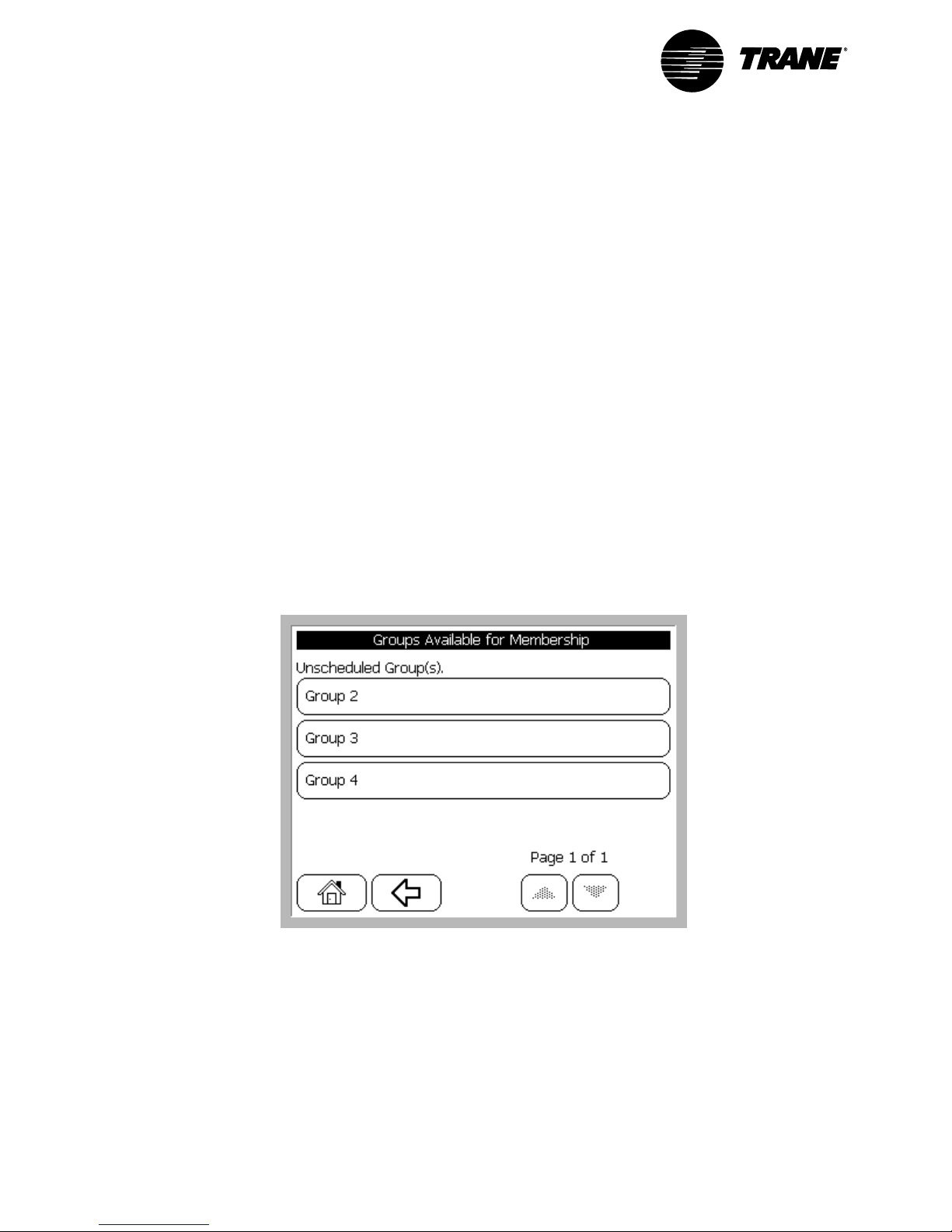
Using the Operator Display
Add Member to Daily Schedule
1 Press Schedule.
2 Press the button for the schedule you want to change. The Schedule Specific
Editor screen displays. The name of the selected schedule is in the Schedule
Name field.
3 Press Schedule Members. The Schedule Members Editor screen displays.
4 Press Add Member. The Groups Available for Membership screen displays.
(See Figure 18.)
5 Press the button for the group you want to add. The Confirmation for Adding
a Member screen displays.
6 Press Yes to confirm the change. The Groups Available for Membership
screen displays.
7 Repeat Steps 5–6 to add additional members to the schedule.
8 Press Home to exit this procedure.
Figure 18. Example of Groups Available for Membership Screen
VAV-SVU01A-EN64
Page 75

Remove Member from Daily Schedule
1 Press Schedule.
2 Press the button for the schedule that you want to change. The Schedule
Specific Editor screen displays with the name of the selected schedule in the
Schedule Name field.
3 Press Schedule Members and the Schedule Members Editor screen
displays.
4 Press Remove Member and the Remove Schedule Member screen displays.
(See Figure 19.)
5 Press the button for the group you want to remove. The Confirmation for
Removing a Member screen displays.
6 Press Yes to confirm the change. The Remove Schedule Member screen
displays.
7 Repeat Steps 5–6 to remove additional members from the schedule.
8 Press Home to exit this procedure.
Figure 19. Example of Remove Schedule Member Screen
VAV-SVU01A-EN 65
Page 76

Using the Operator Display
View List of Daily Schedules and Check Occupancy
1 Press Schedule. The Schedules screen displays the list of schedules and the
current occupancy state.
2 Press Home to exit this procedure.
View a Daily Schedule and Schedule Members
1 Press Schedule.
2 Press Member Listings. The Member and Group Listings screen displays.
3 Press View Schedules and Their Members. The Schedule Membership
Listing screen displays. (See Figure 20.)
4 Press Home to exit this procedure.
Figure 20. Example of Schedule Membership Listing Screen
VAV-SVU01A-EN66
Page 77

View Unscheduled Members
1 Press Schedule.
2 Press Member Listings. The Member and Group Listings screen displays.
3 Press View Unscheduled Groups. The Unscheduled Groups List screen
displays.
4 Press Home to exit this procedure.
Figure 21. Example of Enter or Change the Text Screen
VAV-SVU01A-EN 67
Page 78

Using the Operator Display
Figure 22. After Hours Screen Sequence
Override a
Single Area
Building Information:
Override Areas
Home Page
Start or Restart
Single Area
Timed Override
Cancel Single Area
Timed Override
Confirm Single Area
Timed Override
Confirm Cancel Single
Area Timed Override
After Hours
Schedule Override
Selections
Override a
Single Schedule
Building Information:
Override Schedule
Override Selections
(Single Schedule)
Override All Schedules
and Associated Areas
Start or Restart
Timed Override
Cancel Timed Override
Start or Restart
Timed Override
Cancel Timed Override
Confirm Single
Schedule Timed Override
Confirm Cancel Single
Schedule Timed Override
Confirm All Schedules
Timed Override
Confirm Cancel
All Schedules
Timed Override
VAV-SVU01A-EN68
Page 79

After Hours Procedures
The After Hours function allows you to initiate and cancel occupancy status
overrides of areas and schedules. All After Hours functions begin at the home
screen.
Note: If building occupancy is under higher-level control (e.g., Tracker), the
system responds with timed override prevented.
Start or Restart an Area Timed Override
1 Press After Hours. The Schedule Override Selections screen displays.
Figure 23. Example of Schedule Override Selections Screen
VAV-SVU01A-EN 69
Page 80

Using the Operator Display
2 Press Override a Single Area. The Building Information: Override Areas
screen displays.
Figure 24. Example of Building Information: Override Areas Screen
3 Press the button for the area that you want to override. The Override
Selections (Single Area) screen displays.
Figure 25. Example of Override Selections (Single Area)
VAV-SVU01A-EN70
Page 81

4 Press Start or Restart Timed Override. The Confirm Single Area Timed
Override screen displays. (See Figure 26.)
5 Press OK. The Building Information: Override Areas screen displays.
6 To override additional areas, repeat Steps 3–5.
7 Press Home to exit this procedure.
Figure 26. Example of Confirm Single Area Timed Override Screen
VAV-SVU01A-EN 71
Page 82

Using the Operator Display
Start or Restart Timed Override of a Single
Schedule
1 Press After Hours. The Schedule Override Selections screen displays.
2 Press Override a Single Schedule. The Building Information: Override Areas
screen displays.
3 Press the button for the schedule you want to override. The Override
Selections (Single Schedule) screen displays.
4 Press Start or Restart Timed Override. The Confirm Single Schedule Timed
Override screen displays.
5 Press OK. The Building Information: Override Areas screen displays.
6 To override additional schedules repeat Steps 3–5.
7 Press Home to exit this procedure.
Start or Restart All Timed Override Schedules
1 Press After Hours. The Schedule Override Selections screen displays.
2 Press Override All Schedules and Associated Areas. The Override
Selections (All Schedules) screen displays.
3 Press Start or Restart Timed Override. The Confirm All Schedules Timed
Override screen displays.
4 Press OK. The Schedule Override Selections screen displays.
5 Press Home to exit this procedure.
Cancel a Single Area Timed Override
1 Press After Hours. The Schedule Override Selections screen displays.
2 Press Override a Single Area. The Building Information: Override Areas
screen displays.
3 Press the button for the area that you want to override. The Override
Selections (Single Area) screen displays.
4 Press Cancel Timed Override. The Confirm Cancel Single Area Timed
Override screen displays.
5 Press OK. The Building Information: Override Areas screen displays.
6 To cancel additional overrides, repeat Steps 3–5.
7 Press Home to exit this procedure.
VAV-SVU01A-EN72
Page 83

Cancel Timed Override of a Single Schedule
1 Press After Hours. The Schedule Override Selections screen displays.
2 Press Override a Single Schedule. The Building Information: Override
Schedule screen displays.
3 Press the button for the schedule that you want to override. The Override
Selections (Single Schedule) screen displays.
4 Press the Cancel Timed Override button. The Confirm Cancel Timed Override
screen displays.
5 Press OK. The Building Information: Override Schedule screen displays.
6 To cancel additional overrides, repeat Steps 3–5.
7 Press Home to exit this procedure.
Cancel Timed Override of All Schedules
1 Press After Hours. The Schedule Override Selections screen displays.
2 Press Override All Schedules and Associated Areas. The Override
Selections (All Schedules) screen displays.
3 Press Cancel Timed Override. The Confirm Cancel Timed Overrides screen
displays.
4 Press OK. The Schedule Override Selections screen displays.
5 Press Home to exit this procedure.
VAV-SVU01A-EN 73
Page 84

Using the Operator Display
VAV-SVU01A-EN74
Page 85

Chapter 9
Advanced Functions
The Advanced function allows you to perform in-depth setup and/or monitor
detailed status of four subfunctions. All Advanced functions begin at the home
screen. The subfunctions are:
CCP Setup and Service. Allows setup and service of the actual CCP panel,
including time and date.
System Setup and Status. Allows setup and status of the VariTrac system,
including discharge air temperature and static air pressure setpoints.
Zone Setup and Status. Allows setup and status of factors pertaining to the
VariTrac zones, including zone heating and cooling setpoints.
Group Setup. Allows setup of factors pertaining to the VariTrac groups,
including ventilation mode and flow override.
CCP Setup and Service
CCP Setup
CCP Setup allows you to set the current time, set the current date, select the
time format, and choose the units of display. To access CCP Setup from the
home screen:
1 Press Advanced.
2 Press CCP Setup and Service.
3 Press CCP Setup. The CCP Setup Selections screen appears.
VAV-SVU01A-EN
75
Page 86

Advanced Functions
Figure 27. Example of CCP Setup Selections Screen
Set the Current Time
1 Press Current Time. The Enter a Time screen displays.
2 Enter the time. Make sure to choose AM or PM. You will see the time
change on the left side as you enter it.
3 Press OK.
4 Press Yes to verify your entry. The CCP Setup Selections screen appears.
Set the Current Date
1 Press Current Date. The Enter a Date screen displays.
2 Enter the correct date using DD-MMM-YYYY format. The date changes on
the left side as you enter.
Note: After the day of the month is entered, the entry buttons change to
month selections. After you enter the month, the screen again displays
numerics where you enter the year.
3 Press OK.
4 Press Yes to verify your entry. The CCP Setup Selections screen appears.
76
VAV-SVU01A-EN
Page 87

Set the Time Format
1 Press Time Format. The Set Time Format screen displays.
2 Press AM/PM or 24 Hour.
3 Press Yes to verify your entry. The CCP Setup Selections screen appears.
To Change the Units of Display
1 Press Units of Display. The Select Units of Measure screen displays.
2 Press Inch-Pound (English) or International System (SI).
3 Press Yes to verify your entry. The CCP Setup Selections screen appears.
Service and Testing
The CCP Service and Testing function allows you to adjust the setup parameters
of the operator display screen. This includes adjusting the screen contrast and
brightness, and calibrating the touch screen so the targets perform properly.
CCP Service and Testing also allows you to perform CCP hardware and software
test and status functions. These functions include viewing the status of the
CCPs inputs and outputs, viewing memory and processor status, rebooting the
panel, and putting the CCP into test mode.
To access CCP Service and Testing from the home screen:
1 Press Advanced.
2 Press CCP Setup and Service.
3 Press Service and Testing. The Service and Test Selections screen displays.
Figure 28. Example of Service and Test Selections Screen
VAV-SVU01A-EN
77
Page 88

Advanced Functions
Operator Display Parameters
Adjust Contrast/Backlight
To adjust contrast and brightness of the operator display:
1 Press Operator Display Parameters.
2 Press Adjust Contrast/Backlight. The Brightness and Contrast screen
displays. Two rows of buttons appear, one for brightness adjustment and one
for contrast adjustment.
3 Press the buttons to the left to reduce contrast and brightness. Press the
buttons to the right to increase contrast and brightness.
4 The screen reflects the change as you press the buttons.
5 Press Back arrow to exit this procedure. The Operator Display Parameters
screen displays.
Figure 29. Example of Adjusting Brightness and Contrast Screen
78
VAV-SVU01A-EN
Page 89

Calibrate Touch Screen
To calibrate the accuracy of the touch screen buttons:
1 Press Calibrate Touch Screen.
2 The touch screen calibration function displays.
3 The screen instructs you to press the calibration target in the upper left hand
corner of the screen. Press until the beeping stops (about 10 beeps).
4 The screen then instructs you to press the calibration target in the lower right
hand corner of the screen. Press until the beeping stops (about 10 beeps).
5 You will automatically be returned to the Operator Display Parameters screen.
6 When you have adjusted the display to your satisfaction, press Home to exit
this procedure.
Figure 30. Example of Calibrating the Touch Screen
VAV-SVU01A-EN
79
Page 90

Advanced Functions
CCP Hardware and Software Functions
To access CCP Service and Testing from the home screen:
1 Press Advanced.
2 Press CCP Setup and Service.
3 Press Service and Testing. The Service and Test Selections screen displays.
(See Figure 31.)
4 Press CCP Hardware and Software. The Hardware and Software Tests
screen displays. (See Figure 32.)
Figure 31. Example of Service and Test Selection Screen
Figure 32. Example of Selecting Hardware and Software Tests Screen
80
VAV-SVU01A-EN
Page 91

Display CCP I/O Status
This screen displays the status of the Priority Shutdown and External Time Clock
Inputs located on the CCP subbase. It also displays the status of the spare relay
output on the optional relay board.
1 Press Display CCP I/O Status to view I/O status. The CCP I/O Status
screens displays.
2 View input/output status of the CCP.
3 Press the Back arrow. The Hardware and Software Tests screen displays.
Memory and Processor Tasks
Rebooting the System. Rebooting the system allows you to restart the CCP,
which is similar to cycling power to the panel.
1 Press Reboot the CCP. The confirmation screen displays.
2 Press Ye s . The CCP panel reboots and the system recalibrates.
View Processor and RAM Usage (status only). Viewing processor and RAM
usage is used primarily for development purposes and is typically not utilized
during field setup or service.
Invoke CCP Diagnostics (Test Mode)
The CCP test mode allows you to manually override the CCP relay outputs and
the bypass damper for service purposes.
To enter test mode from the home screen:
1 Press Advanced. The Setup and Status Selections screen displays.
2 Press CCP Setup and Service. The CCP Setup and Service screen displays.
3 Press Service and Testing. The Service and Test Selections screen displays.
4 Press CCP Hardware and Software. The Hardware And Software Tests
screen displays.
5 Press Invoke CCP Diagnostics. The Test and Diagnostics Selections screen
displays. (See Figure 33.)
6 Press Test Mode: Disabled. The current status of the test mode is displayed.
A warning screen displays to caution you about proper use of test mode.
7 Press Yes to continue. A test mode enable/disable screen displays.
8 Press Enable to continue.
9 Press Yes to the verification screen to continue. The Test and Diagnostics
Selections screen displays.
VAV-SVU01A-EN
81
Page 92

Advanced Functions
Figure 33. Example of Test and Diagnostics Selection Screen
The buttons on the screen allow you to turn the six relays on the optional relay
board on and off to verify operation. The bypass damper button will allow you to
enter a position value between 0 percent and 100 percent to verify damper
operation.
Terminate Test Mode. When finished using the test mode function, the mode
must be properly terminated.
1 Press Test Mode: Enabled. The current status of the test mode is displayed.
A warning screen displays a caution of proper use of the test mode.
2 Press Yes to continue. A test mode enabled/disabled screen will appear.
3 Press Disabled to continue.
4 Press Yes on the verification screen to continue. The Test and Diagnostics
Selections screen displays.
5 Press Home to exit this procedure.
82
VAV-SVU01A-EN
Page 93

System Setup and Status
The System Setup and Status section of Advanced functions allows you to
perform in-depth setup and monitoring of the VariTrac system and associated
HVAC units. There are two parts to this section:
System Setup
System Status
System Setup
To access System Setup from the VariTrac home screen:
1 Press Advanced.
2 Press System Setup and Status.
3 Press System Setup.
4 The first System Setup screen appears. (See Figure 34.) System Setup
consists of four screens. Navigate through the screens using the Up or
Down arrows.
Figure 34. Example of System Setup Screen, page 1
VAV-SVU01A-EN
83
Page 94

Advanced Functions
System Name
Press System Name to enter a description name for the VariTrac CCP. The name
can contain a maximum of 24 characters, including spaces. The default name is
VariTrac CCP. (See Figure 34.)
HVAC Unit Type
Press HVAC Unit Type to select a unit type. The VariTrac system configures this
parameter automatically on start-up, with the exception of Generic Heat Pump
which must be selected manually. The default unit type is Relay Board 2H2C.
(See Figure 34.)
Control Mode
Press Control Mode to select a manual control mode for the HVAC unit. The
default mode is auto, which allows the system to change automatically between
the heating and cooling modes. This is the recommended setting for VariTrac.
You may manually select heat, cool, or off. The system remains in the manually
selected mode until it is manually returned to the auto mode. (See Figure 34.)
Supply Air Tempering
This button only appears if the HVAC unit is a Voyager or Reliatel rooftop unit.
Press this button to enable the Supply Air Tempering function in a Voyager via the
CCP. When enabled, the Voyager cycles a stage of heat on and off to warm up
the supply air stream and better manage the load created by increased ventilation
air requirements. The VariTrac system must be in the heating mode and not
calling for heat. When the supply air temperature falls 10°F below the supply air
tempering setpoint (default 70°F), the Voyager turns on a stage of heat. The
stage turns off when the supply air temperature rises 10°F above the supply air
tempering setpoint. This process continues until the VariTrac system calls for
heat or the system mode changes to cool. The supply air tempering setpoint can
be adjusted via the VariTrac PC software. (See Figure 34.)
Discharge Cooling Setpoint
Press Discharge Cooling Setpoint to change the discharge cooling setpoint.
The VariTrac CCP controls supply air temperature using a discharge air control
algorithm. When the VariTrac system is in the cooling mode and there is a call for
cool from a zone, the CCP controls to the discharge cooling setpoint (default
55°F). The control algorithm is both deviation- and time-based. This allows the
CCP to adjust the number of stages required and the stage cycle rate for the
most consistent supply air temperature control. The control algorithm meets the
minimum on- and off-time requirements when adjusting stages. (See Figure 35.)
Discharge Heating Setpoint
Press Discharge Heating Setpoint to change the discharge heating setpoint.
The VariTrac CCP controls supply air temperature using a discharge air control
algorithm. When the VariTrac system is in the heating mode and there is a call for
heat from a zone, the CCP controls to the discharge heating setpoint (default
110°F). The control algorithm is both deviation- and time-based. This allows the
CCP to adjust the number of stages required and the stage cycle rate for the
most consistent supply air temperature control. The control algorithm meets the
minimum on- and off-time requirements when adjusting stages. (See Figure 35.)
84
VAV-SVU01A-EN
Page 95

Minimum Opposite Callers
Press Minimum Opposite Callers to change the minimum number of normal
callers required for changeover (default 2, data entry range 1–4). The VariTrac CCP
requires a minimum number of opposite calls to change over. All current mode
callers must be satisfied before the system is allowed to change over. A
minimum time between changeovers of 15 minutes (factory default) is enforced.
The counter begins running immediately after a changeover occurs and must
expire before changeover is allowed. The time remaining on the counter is
displayed on another screen. (See Figure 35.)
Example
: Minimum opposite calls to changeover is set to 2. If the system is in
the heating mode and three zones are calling for heat, all three zones must be
satisfied. If two or more zones are calling for cooling, and if the changeover and
all minimum on/off times are satisfied, the system changes over.
Minimum Opposite Strong Callers
Press Minimum Opposite Strong Callers to change the minimum number of
strong callers required for changeover (default 2, data entry range 1–4). A heat/
cool changeover also occurs if enough opposite strong callers exist. (Strong
callers are described in Zone Heat/Cool Call Strength, p. 14.) All current mode
callers
do not
have to be satisfied, but the minimum time to changeover and all
minimum on/off timers must expire before changeover is allowed.
(See Figure 35.)
Note: During the unoccupied mode (all groups unoccupied), the minimum
opposite calls to changeover automatically changes to one so any opposite strong
caller can change the system operating mode.
Figure 35. Example of System Setup Screen, page 2
VAV-SVU01A-EN
85
Page 96

Advanced Functions
Static Pressure Setpoint Multiplier
Press Static Pressure Setpoint Multiplier to change the static pressure
setpoint multiplier. The VariTrac CCP controls the bypass damper(s) using
measured duct static pressure. The CCP compares the measured static pressure
to the static pressure setpoint. (See Figure 36.)
The static pressure setpoint is calculated by taking the reference static
determined at full flow during calibration and multiplying it by the static pressure
setpoint multiplier edited here (default 1.4, data entry range 1.0 to 2.0).
To increase the static pressure setpoint, raise the multiplier. To decrease the
static pressure setpoint, reduce the multiplier.
Figure 36. Example of System Setup Screen, page 3
86
VAV-SVU01A-EN
Page 97

System Balance Mode
In this mode, the CCP automatically prepares the VariTrac system for balancing
by starting the supply fan, disabling heating and cooling, closing the bypass
damper, and opening all zone dampers to their maximum position.
(See Figure 37.)
1 Press Enable System Balance Mode.
2 Press Enabled.
3 Press Yes to verify your entry. The System Balance Setup screen displays.
(See Figure 38.)
Figure 37. Example of System Setup Screen, page 4
VAV-SVU01A-EN
Figure 38. Example of Setting Up System Balance Setup Screen
87
Page 98

Advanced Functions
Notice that the button text has changed to Disable System Balance Mode,
indicating that the balance mode is currently enabled. The system remains in the
balance mode until manually disabled.
Adjust Groups for Balance Mode
Balance mode allows you to close groups of dampers. This shuts off a portion of
the ductwork to compensate for airside diversity.
1 Press Adjust Groups for Balance Mode. The System Balancing: Group
Status screen displays. (See Figure 39.)
2 When a group button is pressed, the button changes from enabled to
disabled. Select the groups you wish to disable (close).
3 Press OK. The System Balance Setup screen reappears.
4 All the dampers assigned to the selected groups are driven from the
maximum position to the closed position.
Figure 39. Example of System Balancing: Group Status Screen
88
VAV-SVU01A-EN
Page 99

Disabling the System Balance Mode
1 Press Advanced.
2 Press System Setup and Status.
3 Press System Setup.
4 Press the Last page arrow button (double arrow).
5 Press System Balance Mode. The System Balance Setup screen displays.
6 Press Disable System Balance Mode.
7 Press Disabled.
8 Press Yes to verify your entry. The System Balance Setup screen displays.
Notice that the button text has changed to Enable System Balance Mode,
indicating that the balance mode has been disabled. This also automatically
releases any overridden groups back to their auto-flow function.
Changing Limits Globally
If the zone sensor setpoint thumbwheel attached to a zone UCM is enabled, the
thumbwheel becomes the active occupied setpoint. The setpoint thumbwheel
can be set anywhere from 50°F to 95°F. Reduce this range to 6°F or less during
system commissioning. The VariTrac CCP allows you to create a single set of
limits for the zone sensor setpoint thumbwheels and broadcast them to all the
zones on the system at one time.
1 Press the Changing Limits Globally button. The Global Setpoint Limits
screen appears. (See Figure 40.)
2 Press each setpoint and enter the desired value. Figure 41 displays
suggested settings.
Figure 40. Example of Global Setpoint Limits Screen
VAV-SVU01A-EN
89
Page 100

Advanced Functions
Figure 41. Example of Global Setpoint Limits Screen with Suggested Settings
When you have completed editing the setpoint limits, press Back. When you exit
the Global Setpoint Limits screen, the limits broadcast automatically to all the
VAV UCMs on the communications link.
Calibrate Now
The system calibration function calibrates the VAV UCMs and determines the
static pressure operating setpoint for the system. (See Bypass Calibration, p. 11.)
The Calibrate Now button manually forces the system to go through the
calibration sequence.
1 Press Calibrate Now.
2 Press No if you wish to cancel your selection.
3 Press Ye s to verify your selection. The CCP returns to the home screen and
begins the calibration sequence.
90
VAV-SVU01A-EN
 Loading...