

Page 1

Programming
Tracer™ MP580/581
Programmable
Controller
CNT-SVP01C-EN
Page 2

Page 3

Programming
Tracer™ MP581
Programmable Controller
CNT-SVP01C-EN
November 2005
Page 4

Tracer MP581 Programmable Controller Programming
This guide and the information in it are the property of American Standard Inc. and may not be used or reproduced in whole or in part,
without the written permission of American Standard Inc. Since Trane has a policy of continuous product improvement, it reserves the
right to change design and specification without notice.
Although Trane has tested the hardware and software described in this guide, no guarantee is offered that the hardware and software
are error free.
Trane reserves the right to revise this publication at any time and to make changes to its content without obligation to notify any
person of such revision or change.
Trane may have patents or patent applications covering items in this publication. By providing this document, Trane does not imply
giving license to these patents.
The following are trademarks or registered trademarks of American Standard Inc.: Climate Changer, Rover, Tracer, Tracer
®
™
™
Printed in the U.S.A.
© 2005 American Standard All rights reserved
Summit, and T-Series
The following are trademarks or registered trademarks of their respective companies or organizations: LonMark and LonTalk
®
and Neuron from Echelon Corporation.
CNT-SVP01C-EN
Page 5

Revision history
Document number
and date
CNT-SVP01C-EN
November 2005
Note: This document, in printed form or as an electronic file on a product CD, is accurate as of its publication date.
The electronic version of this document may display a more current publication date and a higher revision level than
this document.
Description
• Thumbwheel linear resistance values table added
CNT-SVP01C-EN
Page 6

NOTICE:
Warnings and Cautions appear at appropriate sections throughout this manual. Read these carefully:
WARNING
Indicates a potentially hazardous situation, which, if not avoided, could result in death or serious injury.
CAUTION
Indicates a potentially hazardous situation, which, if not avoided, may result in minor or moderate injury.
It may also be used to alert against unsafe practices.
CAUTION
Indicates a situation that may result in equipment or property-damage-only accidents.
The following format and symbol conventions appear at appropriate sections throughout this manual:
IMPORTANT
Alerts installer, servicer, or operator to potential actions that could cause the product or system to
operate improperly but will not likely result in potential for damage.
Note:
A note may be used to make the reader aware of useful information, to clarify a point, or to describe
options or alternatives.
CNT-SVP01C-EN
Page 7

Contents
Chapter 1 Overview. . . . . . . . . . . . . . . . . . . . . . . . . . . . . . . . . . 1
Tracer MP580/581 plug-in. . . . . . . . . . . . . . . . . . . . . . . . . . . . . . . . . . . . . . 1
Using Rover service tool . . . . . . . . . . . . . . . . . . . . . . . . . . . . . . . . . . . . . . 1
Accessing the Tracer MP580/581 . . . . . . . . . . . . . . . . . . . . . . . . . . . . 1
Using online Help. . . . . . . . . . . . . . . . . . . . . . . . . . . . . . . . . . . . . . . . . 2
Chapter 2 Viewing status . . . . . . . . . . . . . . . . . . . . . . . . . . . . . 3
Viewing the status of inputs . . . . . . . . . . . . . . . . . . . . . . . . . . . . . . . . . . . 4
Viewing the status of binary and analog outputs . . . . . . . . . . . . . . . . . . 5
Overriding binary and analog outputs . . . . . . . . . . . . . . . . . . . . . . . . . . . 6
Releasing binary and analog output overrides . . . . . . . . . . . . . . . . . . . . 9
Viewing the status of binary and analog variables . . . . . . . . . . . . . . . . . 9
Viewing application status. . . . . . . . . . . . . . . . . . . . . . . . . . . . . . . . . . . . 12
Viewing Comm5 parameters . . . . . . . . . . . . . . . . . . . . . . . . . . . . . . . . . . 13
Viewing custom displays . . . . . . . . . . . . . . . . . . . . . . . . . . . . . . . . . . . . . 14
Changing binary and analog variables . . . . . . . . . . . . . . . . . . . . . . . . . . 15
Overriding the occupancy mode . . . . . . . . . . . . . . . . . . . . . . . . . . . . . . . 16
Applying an occupancy override . . . . . . . . . . . . . . . . . . . . . . . . . . . 16
Releasing an occupancy override . . . . . . . . . . . . . . . . . . . . . . . . . . . 17
Chapter 3 Configuring the Tracer MP580/581 . . . . . . . . . . . . 19
CNT-SVP01C-EN v
Configuring EX2 expansion modules . . . . . . . . . . . . . . . . . . . . . . . . . . . 19
Configuring inputs . . . . . . . . . . . . . . . . . . . . . . . . . . . . . . . . . . . . . . . . . . 21
Configuring binary inputs . . . . . . . . . . . . . . . . . . . . . . . . . . . . . . . . . 21
Configuring analog inputs. . . . . . . . . . . . . . . . . . . . . . . . . . . . . . . . . 24
Configuring pulse inputs . . . . . . . . . . . . . . . . . . . . . . . . . . . . . . . . . . 26
Configuring outputs . . . . . . . . . . . . . . . . . . . . . . . . . . . . . . . . . . . . . . . . . 28
Configuring binary outputs . . . . . . . . . . . . . . . . . . . . . . . . . . . . . . . . 28
Configuring analog outputs . . . . . . . . . . . . . . . . . . . . . . . . . . . . . . . 29
Configuring variables . . . . . . . . . . . . . . . . . . . . . . . . . . . . . . . . . . . . . . . . 31
Configuring binary variables. . . . . . . . . . . . . . . . . . . . . . . . . . . . . . . 31
Configuring analog variables . . . . . . . . . . . . . . . . . . . . . . . . . . . . . . 33
Configuring user security. . . . . . . . . . . . . . . . . . . . . . . . . . . . . . . . . . . . . 35
Page 8

Contents
Setting the time and date . . . . . . . . . . . . . . . . . . . . . . . . . . . . . . . . . . . . . 37
Configuring timers . . . . . . . . . . . . . . . . . . . . . . . . . . . . . . . . . . . . . . . . . . 38
Configuring the operator display. . . . . . . . . . . . . . . . . . . . . . . . . . . . . . . 39
Configuring the home display . . . . . . . . . . . . . . . . . . . . . . . . . . . . . . 39
Configuring custom displays. . . . . . . . . . . . . . . . . . . . . . . . . . . . . . . 41
Configuring an SCC or DAC profile . . . . . . . . . . . . . . . . . . . . . . . . . . . . . 44
Configuring the SCC interface . . . . . . . . . . . . . . . . . . . . . . . . . . . . . . 44
Configuring the DAC interface. . . . . . . . . . . . . . . . . . . . . . . . . . . . . . 45
Configuration reports . . . . . . . . . . . . . . . . . . . . . . . . . . . . . . . . . . . . . . . . 47
Saving configuration reports . . . . . . . . . . . . . . . . . . . . . . . . . . . . . . . 47
Printing configuration reports . . . . . . . . . . . . . . . . . . . . . . . . . . . . . . 47
Memory reset . . . . . . . . . . . . . . . . . . . . . . . . . . . . . . . . . . . . . . . . . . . . . . 48
Unlocking controller for flash download. . . . . . . . . . . . . . . . . . . . . . . . . 48
Chapter 4 Using the Schedule application . . . . . . . . . . . . . . 49
Viewing the status of the time-of-day schedule . . . . . . . . . . . . . . . . . . . 49
Setting up the daily schedule. . . . . . . . . . . . . . . . . . . . . . . . . . . . . . . . . . 50
Clearing a start or stop time . . . . . . . . . . . . . . . . . . . . . . . . . . . . . . . 52
Clearing the event times for a day . . . . . . . . . . . . . . . . . . . . . . . . . . 52
Clearing all daily event times. . . . . . . . . . . . . . . . . . . . . . . . . . . . . . . 53
Copying a daily schedule . . . . . . . . . . . . . . . . . . . . . . . . . . . . . . . . . . 53
Setting up the exception schedule. . . . . . . . . . . . . . . . . . . . . . . . . . . . . . 54
Adding an exception. . . . . . . . . . . . . . . . . . . . . . . . . . . . . . . . . . . . . . 54
Clearing an exception. . . . . . . . . . . . . . . . . . . . . . . . . . . . . . . . . . . . . 55
Editing an exception . . . . . . . . . . . . . . . . . . . . . . . . . . . . . . . . . . . . . . 56
Setting up occupancy inputs . . . . . . . . . . . . . . . . . . . . . . . . . . . . . . . . . . 57
Synchronizing time with Tracer Summit . . . . . . . . . . . . . . . . . . . . . . . . . 59
Controlling the occupancy mode of the Tracer MP580/581. . . . . . . . . . 59
Manual command. . . . . . . . . . . . . . . . . . . . . . . . . . . . . . . . . . . . . . . . 59
Time schedule. . . . . . . . . . . . . . . . . . . . . . . . . . . . . . . . . . . . . . . . . . . 60
Occupancy sensor. . . . . . . . . . . . . . . . . . . . . . . . . . . . . . . . . . . . . . . . 60
Occupancy binary input . . . . . . . . . . . . . . . . . . . . . . . . . . . . . . . . . . . 60
Bypass timer . . . . . . . . . . . . . . . . . . . . . . . . . . . . . . . . . . . . . . . . . . . . 61
Chapter 5 Using the Calculations application . . . . . . . . . . . 65
Viewing the status of a calculation . . . . . . . . . . . . . . . . . . . . . . . . . . . . . 65
Setting up a calculation . . . . . . . . . . . . . . . . . . . . . . . . . . . . . . . . . . . . . . 66
Clearing a calculation . . . . . . . . . . . . . . . . . . . . . . . . . . . . . . . . . . . . . . . . 69
vi CNT-SVP01C-EN
Page 9

Contents
Chapter 6 Graphical programming overview . . . . . . . . . . . . 71
Opening the TGP editor . . . . . . . . . . . . . . . . . . . . . . . . . . . . . . . . . . . . . . 71
TGP editor . . . . . . . . . . . . . . . . . . . . . . . . . . . . . . . . . . . . . . . . . . . . . . . . . 72
Design space. . . . . . . . . . . . . . . . . . . . . . . . . . . . . . . . . . . . . . . . . . . . 72
Output display . . . . . . . . . . . . . . . . . . . . . . . . . . . . . . . . . . . . . . . . . . 72
Blocks . . . . . . . . . . . . . . . . . . . . . . . . . . . . . . . . . . . . . . . . . . . . . . . . . 73
Menu bar. . . . . . . . . . . . . . . . . . . . . . . . . . . . . . . . . . . . . . . . . . . . . . . 73
Toolbars . . . . . . . . . . . . . . . . . . . . . . . . . . . . . . . . . . . . . . . . . . . . . . . 73
Standard toolbar . . . . . . . . . . . . . . . . . . . . . . . . . . . . . . . . . . . . . 74
Alignment toolbar . . . . . . . . . . . . . . . . . . . . . . . . . . . . . . . . . . . . 74
Block toolbars. . . . . . . . . . . . . . . . . . . . . . . . . . . . . . . . . . . . . . . . 75
Program toolbar. . . . . . . . . . . . . . . . . . . . . . . . . . . . . . . . . . . . . . 76
Showing or hiding toolbars . . . . . . . . . . . . . . . . . . . . . . . . . . . . 76
Short cut menus. . . . . . . . . . . . . . . . . . . . . . . . . . . . . . . . . . . . . . . . . 77
Keyboard short cuts . . . . . . . . . . . . . . . . . . . . . . . . . . . . . . . . . . . . . . . . . 77
Chapter 7 Creating a graphical program . . . . . . . . . . . . . . . . 79
Creating a new program . . . . . . . . . . . . . . . . . . . . . . . . . . . . . . . . . . . . . 79
Opening an existing program . . . . . . . . . . . . . . . . . . . . . . . . . . . . . . . . . 79
Editing program properties . . . . . . . . . . . . . . . . . . . . . . . . . . . . . . . . . . . 80
Setting page width and size. . . . . . . . . . . . . . . . . . . . . . . . . . . . . . . . . . . 82
Adding a block . . . . . . . . . . . . . . . . . . . . . . . . . . . . . . . . . . . . . . . . . . . . . 82
Editing block properties . . . . . . . . . . . . . . . . . . . . . . . . . . . . . . . . . . . . . . 83
Adding a comment . . . . . . . . . . . . . . . . . . . . . . . . . . . . . . . . . . . . . . . . . . 84
Arranging blocks. . . . . . . . . . . . . . . . . . . . . . . . . . . . . . . . . . . . . . . . . . . . 84
Moving blocks. . . . . . . . . . . . . . . . . . . . . . . . . . . . . . . . . . . . . . . . . . . 84
Aligning blocks . . . . . . . . . . . . . . . . . . . . . . . . . . . . . . . . . . . . . . . . . . 85
Deleting a block. . . . . . . . . . . . . . . . . . . . . . . . . . . . . . . . . . . . . . . . . . . . . 85
Connecting blocks using wired connections . . . . . . . . . . . . . . . . . . . . . 85
Connecting blocks using wireless connections . . . . . . . . . . . . . . . . . . . 86
Refreshing the TGP editor . . . . . . . . . . . . . . . . . . . . . . . . . . . . . . . . . . . . 91
Saving a program . . . . . . . . . . . . . . . . . . . . . . . . . . . . . . . . . . . . . . . . . . . 91
Printing a program . . . . . . . . . . . . . . . . . . . . . . . . . . . . . . . . . . . . . . . . . . 91
Closing a program . . . . . . . . . . . . . . . . . . . . . . . . . . . . . . . . . . . . . . . . . . 91
Chapter 8 Using the Occupancy and PID blocks. . . . . . . . . . 93
CNT-SVP01C-EN vii
Using the Occupancy block . . . . . . . . . . . . . . . . . . . . . . . . . . . . . . . . . . . 93
Using the Occupancy block to turn on a supply fan . . . . . . . . . . . . 94
Using the Occupancy block to adjust setpoints. . . . . . . . . . . . . . . . 94
Page 10

Contents
Using the PID block . . . . . . . . . . . . . . . . . . . . . . . . . . . . . . . . . . . . . . . . . . 97
Setting up the PID block properties. . . . . . . . . . . . . . . . . . . . . . . . . . 97
Incorporating the PID block . . . . . . . . . . . . . . . . . . . . . . . . . . . . . . . 100
Chapter 9 Implementing a graphical program . . . . . . . . . . 103
Compiling a program . . . . . . . . . . . . . . . . . . . . . . . . . . . . . . . . . . . . . . . 103
Downloading a program. . . . . . . . . . . . . . . . . . . . . . . . . . . . . . . . . . . . . 103
Uploading a program . . . . . . . . . . . . . . . . . . . . . . . . . . . . . . . . . . . . . . . 104
Deleting a program from the Tracer MP580/581. . . . . . . . . . . . . . . . . . 104
Viewing program status . . . . . . . . . . . . . . . . . . . . . . . . . . . . . . . . . . . . . 104
Debugging a program. . . . . . . . . . . . . . . . . . . . . . . . . . . . . . . . . . . . . . . 105
Simulating a program. . . . . . . . . . . . . . . . . . . . . . . . . . . . . . . . . . . . . . . 106
Chapter 10 Network variable bindings . . . . . . . . . . . . . . . . . 109
Overview . . . . . . . . . . . . . . . . . . . . . . . . . . . . . . . . . . . . . . . . . . . . . . . . . 109
Network variables . . . . . . . . . . . . . . . . . . . . . . . . . . . . . . . . . . . . . . . 109
Binding network variables . . . . . . . . . . . . . . . . . . . . . . . . . . . . . . . . 109
Tracer MP580/581 bindings . . . . . . . . . . . . . . . . . . . . . . . . . . . . . . . . . . 110
Receiving data. . . . . . . . . . . . . . . . . . . . . . . . . . . . . . . . . . . . . . . . . . 110
Sending data . . . . . . . . . . . . . . . . . . . . . . . . . . . . . . . . . . . . . . . . . . . 115
Examples of network variable bindings . . . . . . . . . . . . . . . . . . . . . . . . 118
Example 1: Display sensor readings from a Tracer MP503 on a Tracer
MP581 operator display. . . . . . . . . . . . . . . . . . . . . . . . . . . . . . . . . 118
Example 2: Display sensor readings from a Tracer MP503 on two
different Tracer MP581 operator displays . . . . . . . . . . . . . . . . . . 120
Example 3: Control a binary output on the Tracer MP503 from a
Tracer MP581 . . . . . . . . . . . . . . . . . . . . . . . . . . . . . . . . . . . . . . . . . 122
Example 4: Use a sensor reading on a Tracer MP503 to control a
pump VFD on a Tracer MP581. . . . . . . . . . . . . . . . . . . . . . . . . . . . 123
Index . . . . . . . . . . . . . . . . . . . . . . . . . . . . . . . . . . . 127
viii CNT-SVP01C-EN
Page 11

Chapter 1
Overview
The Tracer MP581 programmable controller is a general-purpose, input/
output device. The controller provides direct digital control of a variety of
HVAC equipment.
The Tracer MP580 is factory-installed on Modular Climate Changer and
on T-Series air handlers. The controller is factory wired to all sensors,
actuators, valves, starters, and other items shipped with the air handler.
Use this programming guide to configure and program the Tracer MP580/
581.
Tracer MP580/581 plug-in
The Rover service tool is the setup and configuration tool for the Tracer
MP580/581. It is analogous to PCM Edit for the PCM and UPCM Edit for
the UPCM. For more information about the Rover service tool, see the
Rover Operation and Programming guide (EMTX-SVX01E-EN).
To access the device through the Rover service tool, you must have the
Tracer MP580/581 plug-in. The plug-in is a software file that Rover connects with internally to display information and set up configuration for
the device. The plug-in also contains extensive online Help to help you
access and change device information.
The Tracer MP580/581 plug-in can be run with Rover Version 4 and
higher. You cannot run the Tracer MP580/581 plug-in with an earlier version of Rover. Updated versions of the Tracer MP580/581 plug-in may be
released independently from the Rover software. Contact your local sales
office for the latest versions of the Rover device plug-ins.
CNT-SVP01C-EN 1
Using Rover service tool
Within Rover, you can access not only status and configuration information but also other applications specific to the Tracer MP580/581.
Accessing the Tracer MP580/581
The Rover service tool communicates to Tracer MP580/581 controllers
through a connection to a Comm5 communication link. Comm5 is Trane’s
implementation of LonTalk
communication link, all communicating devices appear in the Active
Group tree. To access information for a specific device, click that device in
the tree. The device status information appears in the Active Device View
®
. When you start Rover on an active Comm5
Page 12

Chapter 1 Overview
workspace (Figure 1). Use the nine tabs of status information, the seven
command buttons, and this guide to work with the device.
Figure 1. Rover application window
Active
Group
tree
Status tabs
Plug-in
command
buttons
Workspace
Using online Help
The Rover service tool includes online Help for each screen and dialog box
in the plug-in. The extensive online Help does not appear in this guide. To
access Help for a tab or dialog box, click the Help button. For information
about a screen element, such as a field, option, or command button, click
the What’s This? help question mark icon and then click a field. You
can also choose What’s This? from the Help menu and then click a field.
2 CNT-SVP01C-EN
Page 13

Chapter 2
Viewing status
Before viewing the status or configuration of a Tracer MP580/581 controller, you must first select the Tracer MP580/581 you are working with on
the Comm5 link. To select the device, click the device name in the Active
Group tree. The Active Device View appears in the workspace (Figure 2).
The Active Device View contains nine tabs of status information. The
Unit tab is displayed when you first access a device.
The Unit tab displays general status information about the device. The
status information contains the operating status, today’s date and time,
active diagnostics, and expansion module communication status.
Figure 2. Tracer MP580/581 Active Device View in Rover service tool
CNT-SVP01C-EN 3
Page 14

Chapter 2 Viewing status
Viewing the status of inputs
Universal hardware inputs and an additional input for a pressure sensor
are provided on the Tracer MP580/581 controller. The configurable inputs
may be set up as analog or binary. Furthermore, analog inputs may be
configured to accommodate resistance, voltage, or current. You can view
the status of each input as well as its corresponding raw value. For information on configuring inputs, see “Configuring inputs” on page 21.
To view the status of inputs:
X In the Active Device View, click the Inputs tab (Figure 3).
Figure 3. Device status Inputs tab
4 CNT-SVP01C-EN
Page 15

Viewing the status of binary and analog outputs
Viewing the status of binary and
analog outputs
You can view the current status of each hardware output, binary and analog, on the Tracer MP580/581. The status table includes what is currently
controlling the output. Valid control sources, in order of priority, are as
follows (“None” is displayed if there is no control source):
• Operator display or Rover service tool (highest priority)
• Program within the Tracer MP580/581 controller
• Tracer Summit building automation system
To view the status of binary and analog outputs:
X In the Active Device View, click the BOs tab (Figure 4) for the status
of the binary outputs or the AOs tab (Figure 5 on page 6) for the sta-
tus of the analog outputs.
Figure 4. Device status BOs tab
CNT-SVP01C-EN 5
Page 16

Chapter 2 Viewing status
Figure 5. Device status AOs tab
Overriding binary and analog outputs
You can override both binary and analog outputs. Upon override, the
selected output value changes to the override value. The control source of
the output becomes the operator display/service tool so that other control
sources cannot change the value of the output.
Note:
Overrides are maintained through a power loss.
To override a binary or analog output:
1. In the Active Device View, click the BOs tab to view the binary outputs or the AOs tab to view the analog outputs.
2. Click the name of the output in the table that you want to override.
3. Click the Override button. The Override Binary Output dialog box
(Figure 6 on page 7) or the Override Analog Output dialog box
(Figure 7 on page 7) appears.
6 CNT-SVP01C-EN
Page 17

Overriding binary and analog outputs
Figure 6. Override Binary Output dialog box
Figure 7. Override Analog Output dialog box
4. Click the desired override option for binary outputs (Figure 6) or type
the desired override value for analog outputs (Figure 7).
5. Click the Override button. The Current Status field updates, and the
word “Override” appears in bold, blue text (Figure 8 on page 8).
The words “Minimum On/Off” may appear showing that the output
must remain in its current state for the amount of time specified on
the Configuration BOs tab.
CNT-SVP01C-EN 7
Page 18

Chapter 2 Viewing status
Figure 8. Binary output with override
Override
indicator
6. Click Close. The override status of the output appears in the table
(Figure 9). The control source becomes the operator display/service
tool.
Figure 9. BOs status table with an output override
8 CNT-SVP01C-EN
Note:
You can also override a binary or analog output from the Displays tab. Binary and analog outputs must be designated as
adjustable in the display configuration to apply an override to
them. For more information on setting an output to adjustable,
see “Configuring the operator display” on page 39.
Page 19

Releasing binary and analog output overrides
Releasing binary and analog output
overrides
You can release overrides of both binary and analog outputs. Upon
release, the selected output value is released back to normal control. The
control source of the output returns to its original source. To release a
binary or analog output override:
1. In the Active Device View, click the BOs tab to view the binary outputs or the AOs tab to view the analog outputs.
2. Click the output in the table that has its value overridden.
3. Click the Override button. The Override Binary Output dialog box
(Figure 8 on page 8) or the Override Analog Output dialog box
appears.
4. Click the Release button. The Current Status field returns to its original value.
5. Click Close. The status of the output appears in the list.
Note:
You can also release a binary or analog output override from
the Displays tab.
Viewing the status of binary and
analog variables
Variables may be changed using a variety of methods. Variables can be
communicated from the Tracer Summit system and changed using the
Rover service tool. Variables may also be calculated in a program, or they
may be made adjustable through the operator display. The Tracer MP580/
581 accommodates 150 binary and 150 analog variables.
Tracer Summit variables 1 through 30 are reserved for use with the
Tracer Summit building automation system. There are 120 variables controlled by the operator display/service tool and/or programs. These 120
variables are called local variables. You can view the status of each binary
and analog variable.
To aid in troubleshooting, the status table includes the control source
assigning the variable its value. For information on configuring binary
CNT-SVP01C-EN 9
Page 20

Chapter 2 Viewing status
and analog variables, see “Configuring variables” on page 31. Valid control sources include the following:
• Operator display or Rover service tool
• Program within the Tracer MP580/581 controller
• Tracer Summit building automation system
Note:
When Tracer Summit is the control source, no graphical programming is required. The variable can be controlled directly.
To view the status of binary and analog variables:
1. In the Active Device View, click the BVs tab (Figure 10) for the status
of the binary variables or the AVs tab (Figure 11 on page 11) for the
status of the analog variables.
2. Click the Tracer Summit Binary Variables option, the Local Binary
Variables option, the Tracer Summit Analog Variables option, or the
Local Analog Variables option to view the list of variables you want.
Uploading the variables may take a few seconds.
Figure 10. Device status BVs tab displaying local binary variables
Local Binary
Variables option
10 CNT-SVP01C-EN
Page 21

Tracer Summit Analog
Variables option
Viewing the status of binary and analog variables
Figure 11. Device status AVs tab displaying Tracer Summit analog
variables
CNT-SVP01C-EN 11
Page 22

Chapter 2 Viewing status
Viewing application status
You can view the status of the Schedule and standard Calculations applications. On the Application tab under Schedule, view the current occupancy state of the controller as well as the day and time in the controller.
Under Calculations, view the table that displays the calculations present
in the controller as well as the calculation type, units, and values.
To view the application status:
X In the Active Device View, click the Application tab (Figure 12).
Figure 12. Device status Application tab
12 CNT-SVP01C-EN
Page 23

Viewing Comm5 parameters
Viewing Comm5 parameters
To view information about the Tracer MP580/581 controller Comm5
parameters:
X In the Active Device View, click the General tab. Comm5 information
specific to the selected Tracer MP580/581 controller is displayed
(Figure 13).
Figure 13. Device status General tab
CNT-SVP01C-EN 13
Page 24

Chapter 2 Viewing status
Viewing custom displays
You can set up custom displays for the Tracer MP580/581 operator display through the Rover service tool. A custom display is a group of inputs,
outputs, and variables saved under a descriptive name. You can view the
status of the items in the group from the operator display or Rover by
accessing the custom display name. Variables and outputs may also be
changed or overridden from the display if they are configured as adjustable. For more information on configuring custom displays, see “Configuring custom displays” on page 41.
To view custom displays:
1. In the Active Device View, click the Displays tab.
2. In the Display drop-down list, click the custom display you want to
view. The names, values, and control sources for the items in the
group appear (Figure 14).
Figure 14. Device status Displays tab
14 CNT-SVP01C-EN
Page 25

Changing binary and analog variables
Changing binary and analog variables
Variables are often used for setpoints so that they can be changed by the
building operator or owner from the operator display. In the Rover service
tool, binary and analog variables can be changed from the Displays tab.
To make a change from the Displays tab or from the operator display, the
following must be true:
• The variable must be a local variable with the control source set to
the operator display/service tool. For information on configuring
binary and analog variables, see “Configuring variables” on page 31.
• The variable must be designated as adjustable in the display configu-
ration. For information on setting a variable to be adjustable, see
“Configuring custom displays” on page 41.
Note:
Variables cannot be changed from the home display on the operator display or in the Rover service tool.
Upon changing, the selected variable value changes to the requested
value. The control source of the variable does not change, so other control
sources, such as the operator display, can still affect the value of the variable.
To change a binary or analog variable in the Rover service tool:
1. In the Active Device View, click the Displays tab.
2. In the Display list, click the name of the custom display that contains
the variable you want to change.
3. In the table, click the name of the variable you want to change.
4. Click the Change button. The Change Local Analog Variable dialog
box appears (Figure 15 on page 16).
Note:
If the Change button is not available, the variable you chose
does not meet the criteria outlined previously.
CNT-SVP01C-EN 15
Page 26

Chapter 2 Viewing status
Figure 15. Change Local Analog Variable dialog box
5. Click the desired state for binary variables or type the desired value
for analog variables.
6. Click the Change button. The value of the variable is changed.
7. Click Close. The changed value appears in the table.
Overriding the occupancy mode
You can override the effective occupancy of the Tracer MP580/581 controller. An occupancy override from the operator display or the Rover service
tool takes priority over all other occupancy requests.
Applying an occupancy override
Upon override, the occupancy value of the Tracer MP580/581 controller
changes to the override value. The control source of the output becomes
the operator display/service tool, preventing other control sources from
changing the occupancy.
To apply an occupancy override:
1. In the Active Device View, click the Unit tab.
2. Click the Override Unit button. The Override Unit Occupancy dialog
box appears (Figure 16 on page 17).
16 CNT-SVP01C-EN
Page 27

Overriding the occupancy mode
Figure 16. Override Unit Occupancy dialog box
3. In the Override list, click the occupancy mode you want.
4. Click the Override button. The current status is changed to the override mode.
5. Click Close. The Override Unit Occupancy dialog box closes.
Releasing an occupancy override
You can release an occupancy override of the Tracer MP580/581. Upon
release, the occupancy value of the selected device is released to normal
control. The control source of the output becomes the normal source.
To release an occupancy override:
1. In the Active Device View, click the Unit tab.
2. Click the Override Unit Occupancy button. The Override Unit Occupancy dialog box appears.
3. Click the Release button. The current status is changed to the normal
mode.
4. Click Close. The Override Unit Occupancy dialog box closes.
CNT-SVP01C-EN 17
Page 28

Chapter 2 Viewing status
18 CNT-SVP01C-EN
Page 29

Chapter 3
Configuring the
Tracer MP580/581
Use the information in this chapter to configure your Tracer MP580/581
controller. Select the Tracer MP580/581 you want to configure from the
Active Group tree and then click the Configuration button. The Configuration dialog box appears with the same tab selected as the tab that was
showing in the Active Device View. You can jump from tab to tab within
the Configuration dialog box without going back to the status tabs in the
Active Device View.
Configuring EX2 expansion modules
The EX2 expansion module is a field-installed expansion module for the
Tracer MP580/581 programmable controller.
Note:
This feature applies to only Tracer MP580/581 Firmware Revision 2 or higher. Follow the procedure for “Viewing Comm5
parameters” on page 13 to view your current revision number.
Up to four EX2s can be connected to a Tracer MP580/581. Each EX2 adds
the following inputs and outputs to a Tracer MP580/581:
• 6 universal inputs
• 4 binary inputs
• 4 analog outputs
To set up an EX2 expansion module that has been connected to a Tracer
MP580/581:
1. In the Active Device View, click the Unit tab. The status information
for the controller appears.
2. Click the Configuration button. The Configuration dialog box appears
with the Unit tab displayed (Figure 17 on page 20).
3. Under Expansion Module Configuration, in the Expansion Module
Type column, choose the expansion module row for the module you
want to configure. In the list, click the appropriate module type. The
rest of the row fills in with indexes for universal inputs, binary outputs, and analog outputs.
CNT-SVP01C-EN 19
Page 30

Chapter 3 Configuring the Tracer MP580/581
Figure 17. Device configuration Unit tab
The expansion module number is configured by setting the DIP
switch on the module. See the Tracer MP581 Programmable Control-
ler Hardware Installation guide (CNT-SVN01B-EN) for more information.
4. Click the Download button to send your changes to the Tracer
MP580/581. (If the Security Logon dialog box appears, log on.) Click
Close to close the Configuration dialog box.
5. See “Configuring inputs” on page 21 and “Configuring outputs” on
page 28 for instructions on configuring inputs and outputs for the
expansion modules.
20 CNT-SVP01C-EN
Page 31

Configuring inputs
Configuring inputs
Universal hardware inputs and an additional input for a pressure sensor
are provided on the Tracer MP580/581 controller. The configurable inputs
on the controller may be set up as analog or binary. You can configure all
inputs on the controller and any of the expansion modules with the name
and type information. Futhermore, you can configure analog inputs to
accommodate various temperature sensors or to accept a linear resistance, voltage, or current signal. For example, on a zone temperature sensor the linear resistance values for a thumbwheel are displayed in
Table 1:
Table 1. Thumbwheel linear resistance values
Temperature
(°F)
50°F 889.4 Ω
90°F 110.6 Ω
Valu e (Ω)
Configuring binary inputs
A binary input detects whether a circuit is open or closed, indicating on or
off status.
To set up a binary input:
1. In the Active Device View, click the Inputs tab. The status information for the inputs appears.
2. Click the Configuration button. The Configuration dialog box appears
with the Inputs tab displayed (Figure 18, page 22).
CNT-SVP01C-EN 21
Page 32

Chapter 3 Configuring the Tracer MP580/581
Figure 18. Device configuration Inputs tab
3. In the Name list, click the input you want to configure. The configuration information for that input appears in the tab.
You can also select the input by clicking the input number in the
Input list. The Name and Input lists are linked so that input name
and input number are always displayed together.
4. If you want to change the input name, highlight the text and type a
new name.
Use a descriptive name because it appears in custom displays and
programs.
5. Under Type, click the Binary option. The binary input configuration
information appears (Figure 19).
22 CNT-SVP01C-EN
Page 33

Figure 19. Device configuration binary input
Configuring inputs
6. Under Input Definition, type descriptors for the open and closed
states of the binary input.
Use descriptive terms because they appear on the operator display
and the Rover status displays.
CNT-SVP01C-EN 23
Page 34

Chapter 3 Configuring the Tracer MP580/581
7. Complete one of the following options:
• Click another input name in the Name list to edit another input.
• Click another tab to set up another item.
• Click the Download button to send your changes to the Tracer
MP580/581. (If the Security Logon dialog box appears, log on.)
Click Close to close the Configuration dialog box.
Configuring analog inputs
An analog input is a varying voltage, current, or resistance signal that
can be converted to units of measurement, such as temperature, pressure,
and humidity.
To set up an analog input:
1. In the Active Device View, click the Inputs tab. The status information for the inputs appears.
2. Click the Configuration button. The Configuration dialog box appears
with the Inputs tab displayed (Figure 18 on page 22).
3. In the Name list, click the input you want to configure. The configuration information for that input appears in the tab.
You can also select the input by clicking the input number in the
Input list. The Name and Input lists are linked so that input name
and input number are always displayed together.
4. If you want to change the input name, highlight the text and type a
new name.
Use a descriptive name because it appears in custom displays and
programs.
5. Under Type, click the Analog option. The analog input configuration
information appears (Figure 20 on page 25).
24 CNT-SVP01C-EN
Page 35

Figure 20. Device configuration analog input
Configuring inputs
6. In the Type list, click the input type.
Note:
Only the first four universal inputs (Input 01 to Input 04) can
be configured as a Balco or platinum resistance temperature
detector (RTD). Only the first two universal inputs on each EX2
expansion module can be configured as Balco or platinum
RTDs.
7. In the Units list, click the units associated with the input.
8. In the Decimal Places list, click the number of digits you want to
appear to the right of the decimal when displaying the input value.
Determine how many digits appear to the right of the decimal in the
Rover Active Device View and on the Tracer MP580/581 operator display. Use the resolution of the sensor to determine the number of decimal places. For example, if a temperature sensor is accurate to 0.1°F,
do not display more than one decimal place. However, a differential
pressure sensor input may need to display two or three decimal
places.
CNT-SVP01C-EN 25
Page 36

Chapter 3 Configuring the Tracer MP580/581
9. Click to select the Fail at End of Range check box if you want the controller to generate a diagnostic whenever the analog input is within
3% of the end of its range.
For example, a 0–10 V sensor will generate a diagnostic whenever its
raw value is less than 0.3 V or greater than 9.7 V.
10. If the input requires calibration, type the amount you want to adjust
the value of the input in the Calibration Factor field.
For example, if you know a temperature sensor is reading 1°F too
high, type a calibration factor of –1°F.
11. For linear-voltage, -current, or -resistance inputs, type the low and
high sensor values and sensor outputs in the Low and High Sensor
Value and Sensor Output fields.
The Sensor Value Low is the lowest reading the sensor can provide,
while the Sensor Value High is the highest reading the sensor can
provide. For example, a humidity sensor provides a 4–20 mA signal
corresponding to 0–100% relative humidity. Type 0 as the low sensor
value and 100 as the high sensor value in this case. The sensor calibration is determined by these four parameters. In this example, type
4 mA as the low sensor output and 20 mA as the high sensor output.
12. Complete one of the following options:
• Click another input name in the Name list to edit another input.
• Click another tab to set up another item.
• Click the Download button to send your changes to the Tracer
MP580/581. (If the Security Logon dialog box appears, log on.)
Click Close to close the Configuration dialog box.
Configuring pulse inputs
A pulse input measures the number of contact closures over time. Typical
origins of contact closures include electric, gas, and water meters. The
meter must have a dwell time of 200 ms and a maximum pulse rate of
3 pulses per second.
To set up a pulse input:
1. In the Active Device View, click the Inputs tab. The status information for the inputs appears.
2. Click the Configuration button. The Configuration dialog box appears
with the Inputs tab displayed (Figure 18 on page 22).
3. In the Name list, click the input you want to configure. The configuration information for that input appears in the tab.
You can also select the input by clicking the input number in the
Input list. The Name and Input lists are linked so that the input
name and input number are always displayed together.
26 CNT-SVP01C-EN
Page 37
Configuring inputs
4. If you want to change the input name, highlight the text and type a
new name.
Use a descriptive name because it appears in custom displays and
programs.
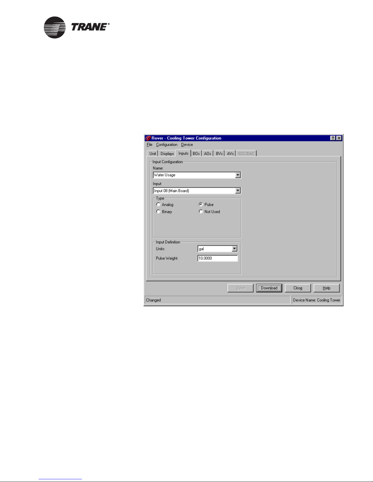
5. Under Type, click the Pulse option. The pulse input configuration
information appears (Figure 21).
Figure 21. Device configuration pulse input
CNT-SVP01C-EN 27
6. In the Units list, click the units associated with the input.
7. In the Pulse Weight field, type the value per contact closure from the
meter.
8. Complete one of the following options:
• Click another input name in the Name list to edit another input.
• Click another tab to set up another item.
• Click the Download button to send your changes to the Tracer
MP580/581. (If the Security Logon dialog box appears, log on.)
Click Close to close the Configuration dialog box.
Page 38

Chapter 3 Configuring the Tracer MP580/581
Configuring outputs
The Tracer MP580/581 and expansion modules include binary and analog
hardware outputs.
Configuring binary outputs
You can name binary outputs, specify open and closed descriptors, and set
minimum on and off times.
To set up a binary output:
1. In the Active Device View, click the BOs tab. The status information
for the binary outputs appears.
2. Click the Configuration button. The Configuration dialog box appears
with the BOs tab displayed (Figure 22).
Figure 22. Device configuration BOs tab
3. In the Name list, click the output you want to configure. The configu-
28 CNT-SVP01C-EN
ration information for that output appears in the tab.
You can also select the output by clicking the output number in the
BO list. The Name and BO lists are linked so that the output name
and output number are always displayed together.
Page 39

Configuring outputs
4. If you want to edit the output name, highlight the text and type a new
name.
Use a descriptive name because it appears in custom displays and
programs.
5. Under Output Definition, type descriptors for the open and closed
states of the binary output.
Use descriptive terms because they appear on the operator display
and the Rover status displays.
6. Under On/Off Times, type the minimum on and off times.
The minimum off time is the least amount of time the output must be
off before it can go to on. The minimum on time is the least amount of
time the output must be on before it can go to off.
7. Complete one of the following options:
• Click another output name in the Name list to edit another out-
put.
• Click another tab to set up another item.
• Click the Download button to send your changes to the Tracer
MP580/581. (If the Security Logon dialog box appears, log on.)
Click Close to close the Configuration dialog box.
Configuring analog outputs
You can name an analog output, specify its type, display its units and
numeric format, and perform calibration.
To set up an analog output:
1. In the Active Device View, click the AOs tab. The status information
for the analog outputs appears.
2. Click the Configuration button. The Configuration dialog box appears
with the AOs tab displayed (Figure 23 on page 30).
CNT-SVP01C-EN 29
Page 40

Chapter 3 Configuring the Tracer MP580/581
Figure 23. Device configuration AOs tab
3. In the Name list, click the output you want to configure. The configuration information for that output appears in the tab.
You can also select the output by clicking the output number in the
AO list. The Name and AO lists are linked so that output name and
output number are always displayed together.
4. If you want to change the output name, highlight the text and type a
new name.
Use a descriptive name because it appears in custom displays and
programs.
5. In the Type list, click the analog output type. This selection sets the
default values under Calibration.
6. In the Units list, click the appropriate units.
7. In the Decimal Places list, click the number of digits you want to
appear to the right of the decimal.
You determine how many digits appear to the right of the decimal in
the Rover Active Device View and on the Tracer MP580/581 operator
display.
8. If the output requires calibration, type the amount by which you want
to adjust the value of the output in the Calibration Factor field.
30 CNT-SVP01C-EN
Page 41

Configuring variables
9. Verify the open and close values and the open and close outputs, and
type new values in the Close and Open Output and Value fields if necessary.
The output values are the hardware output voltage or current corresponding to the open and closed states of the wired device. The analog
output calibration is determined by these four parameters.
10. Click to select the Secondary Control (E-P) check box if a secondary
control device is used and type the open and close values and outputs
for the secondary control device.
11. Complete one of the following options:
• Click another output name in the Name list to edit another out-
put.
• Click another tab to set up another item.
• Click the Download button to send your changes to the Tracer
MP580/581. (If the Security Logon dialog box appears, log on.)
Click Close to close the Configuration dialog box.
Configuring variables
Variables may be changed using a variety of methods. Variables can be
communicated from the Tracer Summit system and changed using the
Rover service tool. Variables may also be calculated in a program, or they
may be made adjustable through the operator display. The Tracer MP580/
581 accommodates 150 binary variables and 150 analog variables.
Configuring binary variables
Tracer Summit binary variables 1 through 30 are reserved for use with
the Tracer Summit system. Use local binary variables 1 through 120 as
local variables. You can edit the Tracer Summit variables or the local
variables. For each binary variable, specify a name, control source, off and
on descriptors, and a communications loss value or initial value.
To set up a binary variable:
1. In the Active Device View, click the BVs tab. The status information
for the binary variables appears.
2. Click the Configuration button. The Configuration dialog box appears
with the BVs tab displayed.
3. Click the Tracer Summit Binary Variables option or the Local Binary
Variables option to view the type of variable you want to edit
(Figure 24 on page 32).
CNT-SVP01C-EN 31
Page 42

Chapter 3 Configuring the Tracer MP580/581
Figure 24. Device configuration BVs tab
4. In the Name list, click the variable you want to configure. The configuration information for that variable appears in the tab.
You can also select the variable by clicking the variable number in the
BV list. The Name and BV lists are linked so that the variable name
and variable number are always displayed together.
5. If you want to change the variable name, highlight the text and type a
new name.
Use a descriptive name because it appears in custom displays and
programs.
6. If the variable is not a Tracer Summit variable, click the control
source for the variable in the Source list.
7. If the variable is local and is controlled by the operator display/service
tool, click to select the Allow Program Control Source check box if you
want to also control this variable within a program.
It is not recommended you select this unless you have a specific purpose in mind, for example, you are using the program to return an
alarm reset variable to normal.
8. Under Variable Definition, type descriptors for the on and off states of
the binary variable.
Use descriptive terms because they appear on the operator display
and the Rover status displays.
32 CNT-SVP01C-EN
Page 43

Configuring variables
9. If the variable has Tracer Summit as its control source, under Communications Loss Value, click the On or Off option to determine what
value you want to appear as the value if Tracer Summit communications are lost to the Tracer MP580/581.
10. If the variable has the operator display and service tool as its control
source, under Value, click the On or Off option to determine what
value you want the variable to have.
Note:
The variable value is saved once every 24 hours. If a power loss
occurs, the variable value is set to the last saved value.
11. Complete one of the following options:
• Click another variable name in the Name list to edit another vari-
able.
• Click another tab to set up another item.
• Click the Download button to send your changes to the Tracer
MP580/581. (If the Security Logon dialog box appears, log on.)
Click Close to close the Configuration dialog box.
Configuring analog variables
Tracer Summit analog variables 1 through 30 are reserved for use with
the Tracer Summit system. The 120 local analog variables are to be used
as local variables. You can edit the Tracer Summit variables or the local
variables. For each analog variable, specify a name, control source, display units, numeric format, and communications loss or initial value.
To set up an analog variable:
1. In the Active Device View, click the AVs tab. The status information
for the analog variables appears.
2. Click the Configuration button. The Configuration dialog box appears
with the AVs tab displayed (Figure 25 on page 34).
CNT-SVP01C-EN 33
Page 44

Chapter 3 Configuring the Tracer MP580/581
Figure 25. Device configuration AVs tab
3. Click the Tracer Summit Analog Variables option or the Local Analog
Variables option to view the type of variable you want to edit.
4. In the Name list, click the variable you want to configure. The configuration information for that variable appears in the tab.
You can also select the variable by clicking the variable number in the
AV list. The Name and AV lists are linked so that the variable name
and variable number are always displayed together.
5. If you want to change the variable name, highlight the text and type a
new name.
Use a descriptive name because it appears in custom displays and
programs.
6. If the variable is not a Tracer Summit variable, click the control
source for the variable.
7. If the variable is local and is controlled by the operator display/service
tool, click to select the Allow Program Control Source check box if you
want to also control this variable within a program.
It is not recommended you select this unless you have a specific purpose in mind.
8. In the Units list, click the appropriate units.
34 CNT-SVP01C-EN
Page 45

Configuring user security
9. In the Decimal Places list, click the number of digits you want to
appear to the right of the decimal when the variable value is displayed.
10. If the variable has Tracer Summit as its source, under Communications Loss Value, type the value you want to appear if Tracer Summit
communications are lost to the Tracer MP580/581.
11. If the variable has the operator display and service tool as its source,
under Value, type the value you want the variable to have.
Note:
The variable value is saved once every 24 hours. If a power loss
occurs, the variable value is set to the last saved value.
12. Complete one of the following options:
• Click another variable name in the Name list to edit another vari-
able.
• Click another tab to set up another item.
• Click the Download button to send your changes to the Tracer
MP580/581. (If the Security Logon dialog box appears, log on.)
Click Close to close the Configuration dialog box.
Configuring user security
A user who has security supervisor access can set up security privileges
for up to eight users, giving each different access privileges, for both the
Tracer MP580/581 operator display and the Rover service tool. Any user
can view all displays on the Tracer MP580/581 operator display; however,
a security supervisor can set up security to prevent unauthorized users
from changing variables or overriding outputs at the operator display.
A security supervisor can also set up security to prevent unauthorized
users from downloading or deleting variables, overriding inputs, downloading or deleting a Tracer graphical program, clearing memory on the
controller, and performing a flash download to the controller.
After security is established, users are prompted to log on with a password when they attempt to perform security-protected functions.
Note:
A logged-on user loses access to security-protected functions if
an action is not performed for 30 minutes.
CNT-SVP01C-EN 35
Page 46
Chapter 3 Configuring the Tracer MP580/581
To configure security:
1. In the Active Device View, click the Unit tab. The status information
for the controller appears.
2. Click the Configuration button. The Configuration dialog box appears
with the Unit tab displayed.
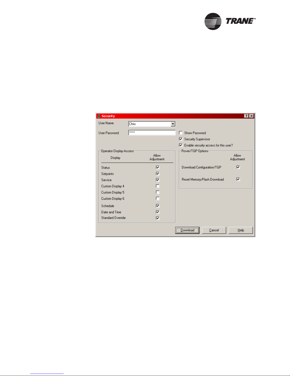
3. Click the Security Setup button. The Security dialog box (Figure 26)
appears.
Figure 26. Security dialog box
4. In the User Name list, click the user name for which you want to set
5. If you want to change the user name, type the user’s name in the User
6. In the User Password field, type a four-digit password.
7. Click to select the Show Password check box to display the password
36 CNT-SVP01C-EN
up security.
Name field.
The user name can be up to 24 characters long.
The password can be only numbers; no letters or special characters
are allowed.
for the selected user name.
Page 47

Setting the time and date
8. If needed, click to select the Security Supervisor check box to set the
selected user as a security supervisor.
At least one user must be declared a security supervisor. After any
default settings have changed, only a security supervisor can change
the security configuration.
9. Under Operator Display Access, click to select the check boxes for the
displays and items you want the selected user to be able to adjust.
Click to clear the check boxes for the displays and items this user is
not allowed to adjust.
The first six check boxes are for the custom displays. The last three
check boxes are for standard displays.
10. Under Rover/TGP Options, click to select the check boxes to allow the
selected user to modify configurations and TGP programs and to be
able to clear memory or download a new program to the Tracer
MP580/581.
11. Repeat steps 4–10 to set up additional users.
12. Click the Download button to send your changes to the Tracer
MP580/581. If the Security Logon dialog box appears, log on. Click
Close to close the Configuration dialog box.
Setting the time and date
Set the time and date for the Tracer MP580/581 and the format in which
you want the time to appear in the Rover service tool and on the operator
display.
To set the time and date:
1. In the Active Device View, click the Unit tab. The status information
for the controller appears.
2. Click the Configuration button. The Configuration dialog box appears
with the Unit tab displayed (Figure 17 on page 20).
3. Under Time Format, click the option for the format in which you want
the time to appear.
4. Under Display, click the Set Date/Time button. (If the Security Logon
dialog box appears, log on.) The Set Date/Time dialog box appears
(Figure 27 on page 38).
CNT-SVP01C-EN 37
Page 48

Chapter 3 Configuring the Tracer MP580/581
Figure 27. Set Date/Time dialog box
5. To select the date and time you want to use, choose one of the following options:
• If you want to apply the current date and time settings of the PC
to the controller, click to select the Use PC System Date/Time
check box.
• If you want to set the date and time for the controller yourself,
click to clear the Use PC System Date/Time check box. Then click
the date in the calendar and type the time. Click to select the
check box if you want to automatically adjust the time for Daylight Savings Time.
6. Click the Set button to apply your changes.
7. Click the Download button to send your changes to the Tracer
MP580/581. If the Security Logon dialog box appears, log on. Click
Close to close the Configuration dialog box.
Configuring timers
Set up the occupied bypass, power-up control wait, and minimum send
times for the Tracer MP580/581.
To set up timers:
1. In the Active Device View, click the Unit tab. The status information
for the controller appears.
2. Click the Configuration button. The Configuration dialog box appears
with the Unit tab displayed (Figure 17 on page 20).
3. In the Occupied Bypass Timer field, type the amount of time you
want the controller to remain in occupied bypass mode.
When a user overrides the controller to occupied bypass mode, it stays
in this mode for the time specified here. This field is not available if
38 CNT-SVP01C-EN
Page 49

Configuring the operator display
an SCC or DAC profile is active. If a profile is active, you must set the
occupied bypass timer on the SCC or DAC Configuration tab.
4. In the Power-up Control Wait field, type the amount of time after
power-up you want the controller to wait before controlling analog or
binary outputs.
5. In the Minimum Send Time field, type the minimum number of seconds between the automatic output of network variable transmissions. Only one output network variable can be updated within a
single minimum-send-time period.
6. Click the Download button to send your changes to the Tracer
MP580/581.
7. Click Close to close the Configuration dialog box.
Configuring the operator display
You can view custom displays from the Rover service tool as well as from
the Tracer MP580/581 operator display. So, custom displays are useful
even when the Tracer MP580/581 does not have a local operator display
connected. In addition, a portable operator display temporarily connected
to the device uses the custom displays.
Use custom displays to logically group the information available in the
Tracer MP580/581. Seven custom displays are available. The first display
is a home display that contains a name and two items. The home display
name appears as the title on the operator display. You can also name the
other six custom displays. Each custom display consists of four screens of
four items, for a total of up to 96 items.
Within a custom display, assign each line to display an input, output, or
variable. Leave a display item blank to break a display into subgroups.
Custom displays allow you to group information by category or by equipment, rather than by point type. For example, all the information pertinent to the cooling tower may be shown on one custom display. Variables
and outputs may be changed or overridden from the custom displays if
the items are configured as adjustable.
CNT-SVP01C-EN 39
Configuring the home display
The home display contains a name or title and two items. The home display name appears as the title on the home screen of the operator display.
The status of the two items is displayed on the home screen as well.
To set up the home display:
1. In the Active Device View, click the Displays tab. The status information appears for the custom displays.
2. Click the Configuration button. The Configuration dialog box appears
with the Displays tab displayed (Figure 28).
Page 50

Chapter 3 Configuring the Tracer MP580/581
Figure 28. Device configuration Displays tab
3. In the Name list, click Home Display. The configuration information
appears in the tab.
4. If you want to change the display name, highlight the text and type a
new name.
Use a descriptive name because it appears on the operator display
and the Active Device View workspace.
5. Click in the first row of the Type column. Click the down arrow. The
Type list appears.
6. In the Type list, click the type of item you want to display.
The types include: inputs, outputs, and variables.
7. Click in the first row of the Display Item Name column. Click the
down arrow. The Display Item Name list appears.
8. In the Display Item Name list, click the name of the item you want to
display.
9. Repeat steps 5–8 for row 2.
10. Complete one of the following options:
• Click another display name in the Name list to edit another dis-
play.
• Click another tab to set up another item.
40 CNT-SVP01C-EN
Page 51

Configuring the operator display
• Click the Download button to send your changes to the Tracer
MP580/581. (If the Security Logon dialog box appears, log on.)
Click Close to close the Configuration dialog box. The changes
appear on the operator display touch screen (Figure 29).
Figure 29. Home display on the operator display
Configuring custom displays
You can set up six custom displays to be displayed in the Rover Active
Device View workspace or on the operator display. Give each display a
descriptive name and assign up to 16 items to the display.
To set up custom displays:
1. In the Active Device View, click the Displays tab. The status information for the custom displays appears.
2. Click the Configuration button. The Configuration dialog box appears
with the Displays tab displayed (Figure 30 on page 42).
CNT-SVP01C-EN 41
Page 52

Chapter 3 Configuring the Tracer MP580/581
Figure 30. Device configuration Displays tab custom display
3. In the Name list, click the display you want to configure. The configuration information for that display appears in the tab.
You can also select the display by clicking the display number in the
Display list. The Name and Display lists are linked so that display
name and display number are always displayed together.
4. If you want to change the display name, highlight the text and type
the new name.
Use a descriptive name because it appears on the operator display
and the Active Device View workspace.
5. Click in the first row of the Type column. Click the down arrow. The
Type list appears.
6. In the Type list, click the type of item you want to display.
The types include: inputs, output, and variables.
7. Click in the first row of the Display Item Name column. Click the
down arrow. The Display Item Name list appears.
8. In the Display Item Name list, click the name of the item you want to
display.
42 CNT-SVP01C-EN
Page 53

Configuring the operator display
9. For outputs and variables with an operator display/service tool control source, click to select the check box in the Adjustable column if
you want the item to be adjustable.
If a variable is adjustable, it can be changed from the operator display. For information on setting a variable control source, see “Configuring variables” on page 31. If an output is adjustable, it can be
overridden from the operator display.
10. If the item is an analog output or variable, and it is adjustable, type
the low and high limits in the columns.
11. Repeat steps 5 through 10 for additional items you want in the custom display.
Leave blank rows to separate groups of items in the display. Four
items appear per screen on the operator display.
12. Complete one of the following options.
• Click another display name in the Name list to edit another dis-
play.
• Click another tab to set up another item.
• Click the Download button to send your changes to the Tracer
MP580/581. (If the Security Logon dialog box appears, log on.)
Click Close to close the Configuration dialog box. The changes
appear on the operator display custom screen (Figure 31).
Figure 31. Custom screen on the operator display
CNT-SVP01C-EN 43
Page 54

Chapter 3 Configuring the Tracer MP580/581
Configuring an SCC or DAC profile
You can set up the Tracer MP580/581 to provide a network interface
according to the Space Comfort Controller (SCC) or Discharge Air Controller (DAC) profile. To implement a one of these profiles, you must complete the following:
• Activate the profile.
• Configure the interface.
• Write a program to implement the configured information. See sam-
ple programs in the Tracer graphical programming library.
To set up an SCC or DAC profile:
1. In the Active Device View, click the Unit tab. The status information
for the controller appears.
2. Click the Configuration button. The Configuration dialog box appears
with the Unit tab displayed (Figure 17 on page 20).
3. Click to select the Activate Profile check box.
4. Click the SCC option to provide a network interface following the
SCC profile or click the DAC option to provide a network interface following the DAC profile.
5. Complete one of the following options:
• Click the SCC or DAC tab to set up the interface. See the follow-
ing sections for more information on configuring the interface.
• Click the Download button to send your changes to the Tracer
MP580/581 and click Close to close the Configuration dialog box
Configuring the SCC interface
To set the configuration parameters associated with the SCC profile:
1. In the Active Device View, click the Configuration button. The Configuration dialog box appears.
2. Click the SCC tab. The SCC configuration information appears
(Figure 32).
Note:
This tab is available only when the SCC profile is active in the
Tracer MP580/581.
44 CNT-SVP01C-EN
Page 55

Configuring an SCC or DAC profile
Figure 32. Device configuration SCC tab
3. Under Units, click the display units option for the SCC profile configuration data.
4. Under Default Setpoints, type the heating and cooling default setpoints for the occupied, unoccupied, and standby modes.
Note:
You need to address only those fields that are used in the program to control the air-handling unit.
5. Under Space, type the CO
limit and the relative humidity setpoint.
2
6. In the Damper Minimum Position field, type the lowest position you
want the outdoor air damper to reach.
7. In the Occupied Bypass Timer field, type the amount of time you
want the controller to remain in occupied bypass mode.
When a user overrides the controller to occupied bypass mode, it stays
in this mode for the time specified here.
8. Click the Download button to send your changes to the Tracer
MP580/581.
9. Click Close to close the Configuration dialog box.
Configuring the DAC interface
To set the configuration parameters associated with the DAC profile:
CNT-SVP01C-EN 45
Page 56

Chapter 3 Configuring the Tracer MP580/581
1. In the Active Device View, click the Configuration button. The Configuration dialog box appears.
2. Click the DAC tab. The DAC configuration information appears
(Figure 33).
Note:
This tab is available only when the DAC profile is active in the
Tracer MP580/581.
Figure 33. Device configuration DAC tab
3. Under Units, click the display units option for the DAC profile config-
4. Under Default Setpoints, type the heating and cooling default set-
5. Under Discharge Air Setpoints, type the discharge air setpoints for
6. Under Static Pressure, type the duct static pressure setpoint and
46 CNT-SVP01C-EN
uration data.
points for the occupied, unoccupied, and standby modes.
Note:
You need to address only those fields that are used in the program to control the air-handling unit.
the DAC profile.
limit and the building static pressure setpoint.
Page 57

Configuration reports
7. Under Air Temperature, type the mixed air temperature low-limit
setpoint and the outdoor air temperature setpoint.
8. In the Occupied Bypass Timer field, type the amount of time you
want the controller to remain in occupied bypass mode.
When a user overrides the controller to occupied bypass mode, it stays
in this mode for the time specified here.
9. Click the Download button to send your changes to the Tracer
MP580/581. Click Close to close the Configuration dialog box.
Configuration reports
After configuring the Tracer MP580/581 controller, you can save and
print reports that include the configuration parameters set up for the controller. These reports can be used to verify the appropriate specifications
for the consulting engineer or to document the specifications for the
customer.
Saving configuration reports
To save a configuration report:
1. In the Active Device View, click the Reports button. The Report Selection dialog box appears.
2. Click to select the check boxes for the configuration items you want in
the report.
3. Click the Save to File button. A Save As dialog box appears.
4. Select or enter a file name for the data that will be saved. Click OK.
The file is saved as a comma-separated values (CSV) file. Use a
spreadsheet program, such as Microsoft Excel, to view the report.
Printing configuration reports
To print a configuration report:
1. In the Active Device View, click the Reports button. The Report Selection dialog box appears.
2. Click to select the check boxes for the configuration items you want in
the report.
3. Click the Print button. The Print dialog box appears.
4. Select the appropriate printer and set the print properties. Click OK.
5. Click OK. The report prints.
CNT-SVP01C-EN 47
Page 58

Chapter 3 Configuring the Tracer MP580/581
Memory reset
If you have security privileges to do so, you can reset the memory of the
controller. Resetting the memory removes all data in the controller database and returns the controller settings back to factory defaults.
Note:
This features applies to only Tracer MP580/581 Firmware Revision 2 or higher. Follow the procedure for “Viewing Comm5
parameters” on page 13 to view your current revision number.
To reset memory:
1. In the Active Device View, click the Configuration button. The Configuration dialog box appears.
2. From the Devices menu, choose Reset Memory. The Reset Memory
dialog appears. (If the Security Logon dialog box appears, log on.)
3. Click the Yes button. The Reset Memory dialog box closes, and the
Rover service tool loses communication with the controller.
4. Click Close to close the Configuration dialog box.
5. From the Group menu, choose Discover to re-establish communication between the Rover service tool and the controller.
Unlocking controller for flash download
The Tracer MP580/581 controller is a host-based controller. Host-based
controllers with flash memory can receive a flash download of new firmware. If security is enabled and you have security privileges, you can
unlock the controller to enable flash downloading. If security is disabled
for all users, unlocking is not required.
Note:
Unlocking the controller applies to only Tracer MP580/581
Firmware Revision 2 or higher. If you have a Revision 1.xx controller, you can perform a flash download without unlocking the
controller. Follow the procedure for “Viewing Comm5 parameters” on page 13 to view your current revision number.
To unlock the controller:
1. In the Active Device View, click the Configuration button. The Configuration dialog box appears.
2. From the Devices menu, choose Unlock Device. (If the Security Logon
dialog box appears, log on.)
3. Backup files as necessary.
4. For details regarding flash downloading (refer to “Performing a Flash
48 CNT-SVP01C-EN
Download” in the Rover Operation and Programming guide, EMTXSVX01C-EN).
Page 59

Chapter 4
Using the Schedule
application
The Tracer MP580/581 plug-in includes a schedule application that you
can use to set up a local schedule. The local schedule functions only when
a non-portable operator display is connected the controller. The local
schedule is used only if Tracer Summit is not communicating on the link.
Use the information in this chapter to set up the local daily schedule and
exceptions for the Tracer MP580/581 controller.
Viewing the status of the time-of-day
schedule
To view the status of the time-of-day schedule:
X In the Active Device View, click the Application tab. The status of the
Tracer MP580/581 applications appears. The current mode of the
schedule and the current day and time of the controller appear under
Schedule (Figure 34).
Figure 34. Time of day schedule status
CNT-SVP01C-EN 49
Page 60
Chapter 4 Using the Schedule application
Setting up the daily schedule
To set up the daily schedule:
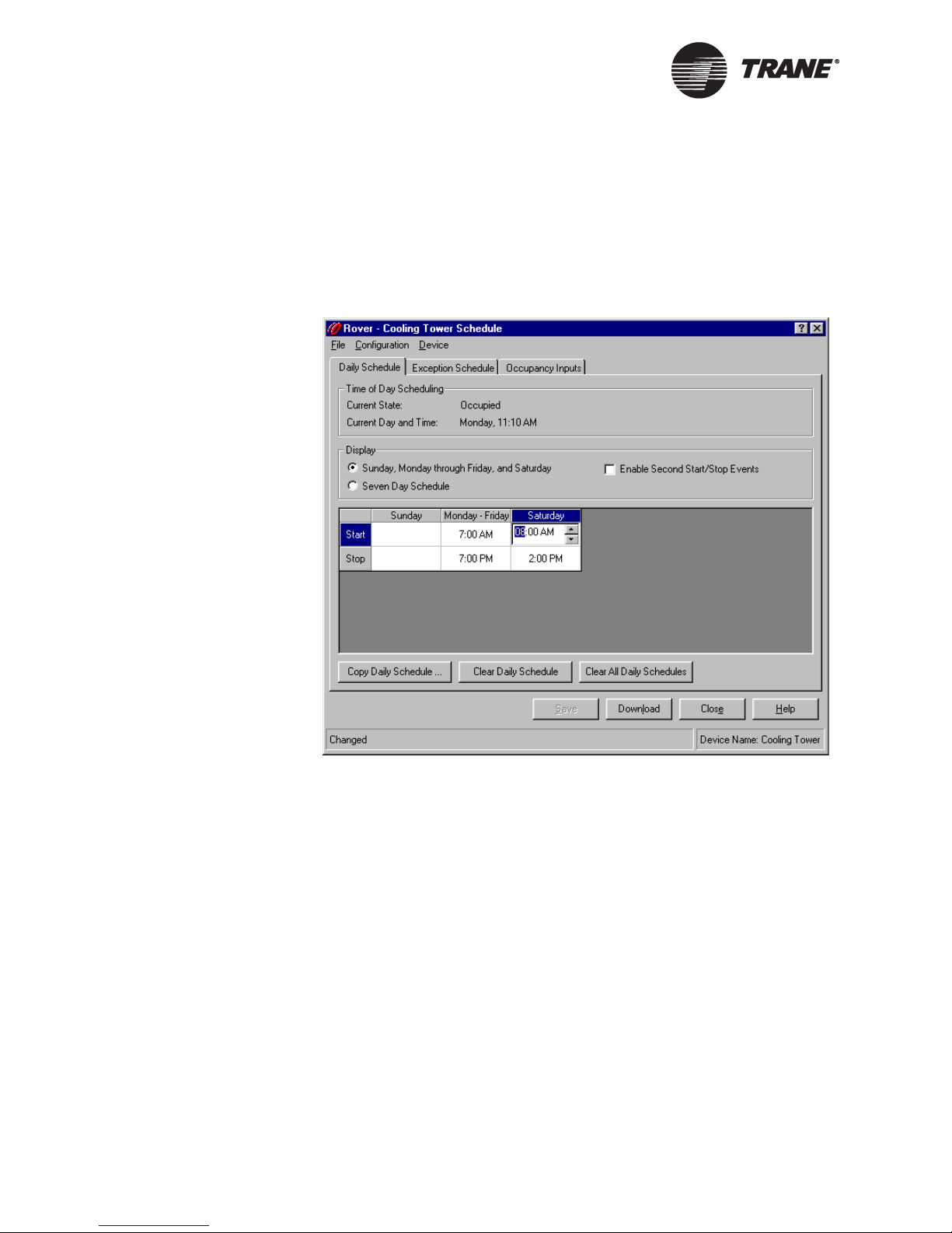
1. In the Active Device View, click the Schedule button. The Schedule
dialog box appears (Figure 35).
Figure 35. Daily Schedule tab in Schedule application
2. Under Display, click the option for the type of schedule you want. The
3. Under Display, click to select the Enable Second Start/Stop Events
50 CNT-SVP01C-EN
daily schedule table changes to include the appropriate number of columns.
If you want to use the same schedule for Monday through Friday, click
the Sunday, Monday through Friday, and Saturday option. Click the
Seven Day Schedule option if you want to specify a different schedule
for each day of the week.
check box if you want to include a second set of start and stop times to
Page 61

the daily schedules. Another set of Start and Stop rows appears in the
daily schedule table.
Note:
The controller does not check event order. It always implements
the last commanded mode. This implies that you could have two
starts or two stops in a row in a single day. Figure 36 illustrates
some examples of event orders. For Example 3, assume that the
previous day ended with a start event. Example 4 shows the
schedule output in the case of two start and stop events in a
row. The second event of the same type is ignored.
Figure 36. Start and stop time examples
Setting up the daily schedule
CNT-SVP01C-EN 51
4. In the daily schedule table, click in the cell for the day-of-the-week
start time.
5. Type the time you want the occupancy to start.
Page 62

Chapter 4 Using the Schedule application
6. Repeat steps 4 and 5 until you have all the start and stop times you
want entered.
If you want no occupied time for a day, enter only a stop time for that
day.
7. Complete one of the following options.
• Make more changes.
• Click another tab in the Schedule application.
• Click the Download button to send your changes to the Tracer
Clearing a start or stop time
To clear a start or stop time:
1. In the Active Device View, click the Schedule button. The Schedule
dialog box appears.
2. In the daily schedule table, select the start or stop time you want to
clear.
3. Press the Delete key.
MP580/581 and click Close to close the Schedule dialog box.
4. Complete one of the following options.
• Make more changes.
• Click another tab in the Schedule application.
• Click the Download button to send your changes to the Tracer
MP580/581 and click Close to close the Schedule dialog box.
Clearing the event times for a day
If event start and stop times have been entered for a particular day and
you do not want any events scheduled for that day, clear the event times
for that day.
To clear the event times for a day:
1. In the Active Device View, click the Schedule button. The Schedule
dialog box appears.
2. In the daily schedule table, click the name of the day you want to
clear.
3. Click the Clear Daily Schedule button. The start and stop times for
that day are cleared.
4. Complete one of the following options.
• Make more changes.
• Click another tab in the Schedule application.
• Click the Download button to send your changes to the Tracer
MP580/581 and click Close to close the Schedule dialog box.
52 CNT-SVP01C-EN
Page 63
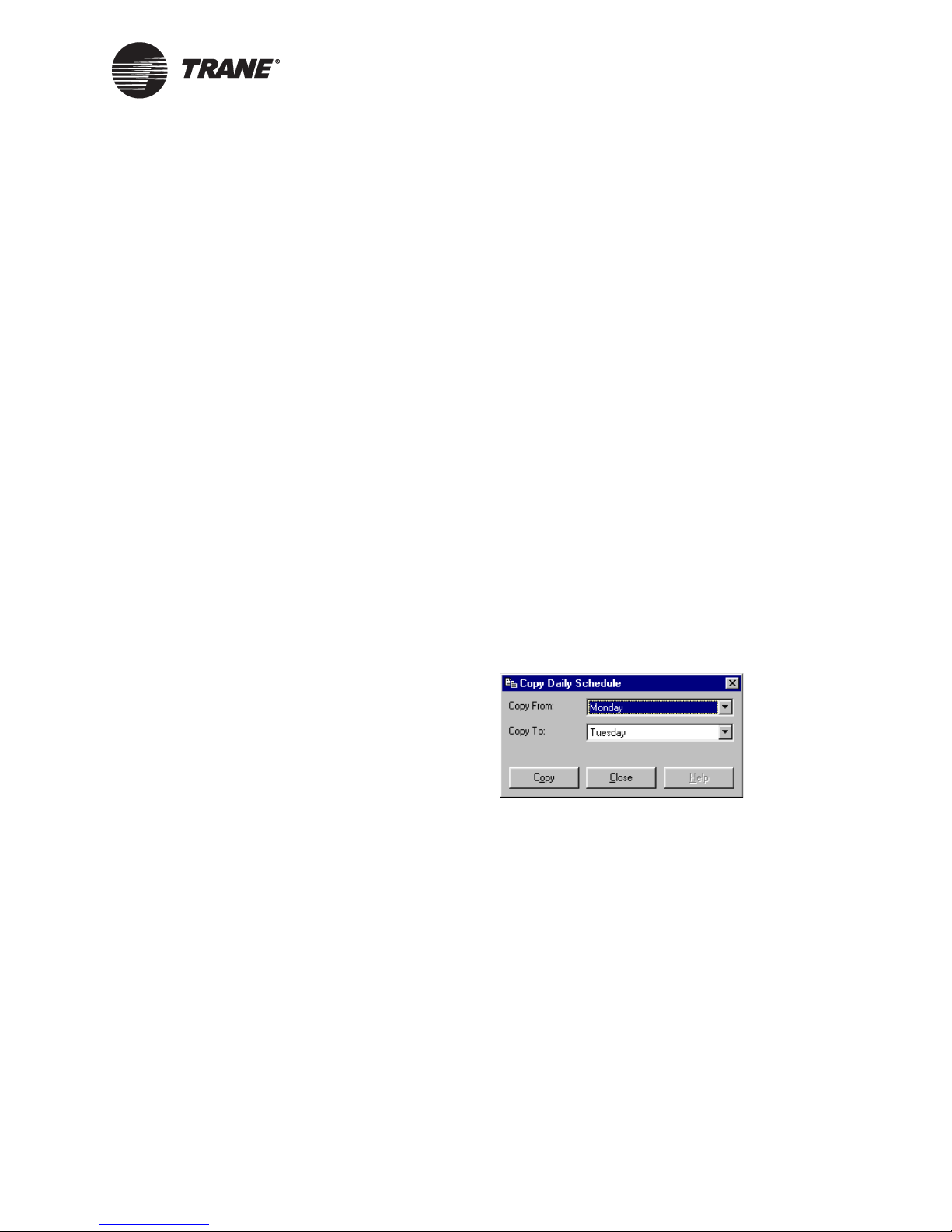
Setting up the daily schedule
Clearing all daily event times
To remove all daily event times at once:
1. In the Active Device View, click the Schedule button. The Schedule
dialog box appears.
2. Click the Clear All Daily Schedules button. All start and stop times
are cleared from the table.
3. Complete one of the following options.
• Make more changes.
• Click another tab in the Schedule application.
• Click the Download button to send your changes to the Tracer
MP580/581 and click Close to close the Schedule dialog box.
Copying a daily schedule
To speed set up and editing time, enter the start and stop times for one
day and then copy that schedule to another day.
To copy a daily schedule:
1. In the Active Device View, click the Schedule button. The Schedule
dialog box appears.
2. Click the Copy Daily Schedule button. The Copy Daily Schedule dialog box appears (Figure 37).
Figure 37. Copy Daily Schedule dialog box
3. In the Copy From list, click the day you want to copy the schedule
from.
4. In the Copy To list, click the day you want to copy the schedule to.
5. Click the Copy button. A message appears stating that the schedule
has been copied.
6. Click OK. The new schedule appears in the table.
7. Copy additional schedules or click Close to close the Copy Daily
Schedule dialog box.
8. Complete one of the following options.
• Make more changes.
• Click another tab in the Schedule application.
• Click the Download button to send your changes to the Tracer
MP580/581 and click Close to close the Schedule dialog box.
CNT-SVP01C-EN 53
Page 64

Chapter 4 Using the Schedule application
Setting up the exception schedule
An exception is a period of time that does not follow the regular schedule—for example, a holiday or an unusual work day or event. You can
add, edit, or clear exceptions to the schedule.
Note:
An exception is cleared automatically once the current date is
past the exception stop date.
Adding an exception
You can set up a maximum of 20 exceptions.
To add an exception:
1. In the Active Device View, click the Schedule button. The Schedule
dialog box appears.
2. Click the Exception Schedule tab (Figure 38 on page 54).
Figure 38. Exception Schedule
3. Click the Add Exception button. A blank exception row appears in the
54 CNT-SVP01C-EN
table.
Page 65

Setting up the exception schedule
4. Type a new name, such as New Years 2002.
Note:
Click and drag the column splitters to adjust the width of the
columns in the table.
5. Click the start date.
6. Highlight the text and type a new date or click the down arrow to
select from the calendar.
7. Enter the stop date, start time, and stop time.
If you want an exception event to have no occupied time, delete the
start time and enter only a stop time, such as 12:00
remains unoccupied until the next start time in the schedule.
8. If you want a second start and stop time, click to select the Enable
Second Start/Stop Event check box.
The controller does not check event order. It always implements the
last commanded mode. This implies that you could have two starts or
two stops in a row in a single day. Figure 36 on page 51 illustrates
some examples of event orders.
9. Complete one of the following options.
A.M. The request
• Make more changes.
• Click another tab in the Schedule application.
• Click the Download button to send your changes to the Tracer
MP580/581 and click Close to close the Schedule dialog box.
Clearing an exception
Clear an exception if you want to follow the normal schedule rather than
a previously entered exception.
To clear an exception:
1. In the Active Device View, click the Schedule button. The Schedule
dialog box appears.
2. Click the Exception Schedule tab.
3. Click in the row of the exception that you want to clear (Figure 39).
CNT-SVP01C-EN 55
Page 66

Chapter 4 Using the Schedule application
Figure 39. Exception row selected
4. Click the Clear Exception button. The exception is removed from the
table.
5. Complete one of the following options.
• Make more changes.
• Click another tab in the Schedule application.
• Click the Download button to send your changes to the Tracer
MP580/581 and click Close to close the Schedule dialog box.
Editing an exception
To change existing exceptions to the schedule:
1. In the Active Device View, click the Schedule button. The Schedule
dialog box appears.
2. Click the Exception Schedule tab.
3. Click the item in the row of the exception you want to change.
4. Highlight the text and type a value.
5. If you want a second start and stop time, click to select the Enable
Second Start/Stop Event check box.
56 CNT-SVP01C-EN
Page 67

Setting up occupancy inputs
6. Complete one of the following options.
• Make more changes.
• Click another tab in the Schedule application.
• Click the Download button to send your changes to the Tracer
MP580/581 and click Close to close the Schedule dialog box.
Setting up occupancy inputs
The effective occupancy of the Tracer MP580/581 controller can be
changed also by other inputs. A timed override is initiated by pressing the
ON button on a Trane zone sensor. A timed override request changes the
occupancy mode from unoccupied to occupied bypass. The controller
remains in occupied-bypass mode until the bypass timer times out or the
CANCEL button on the sensor is pressed.
Note:
Although the occupancy input override request affects the occupancy mode of the Tracer MP580/581 controller, programming
is required for the equipment controlled by the Tracer MP580/
581 to react to this request. See Chapter 8, “Using the Occupancy and PID blocks” for more information.
To set up occupancy inputs:
1. In the Active Device View, click the Schedule button. The Schedule
dialog box appears.
2. Click the Occupancy Inputs tab (Figure 40 on page 58).
CNT-SVP01C-EN 57
Page 68

Chapter 4 Using the Schedule application
Figure 40. Occupancy Inputs tab in Schedule application
3. In the Timed Override Input list, click the universal input you want
to act as the timed override input for the controller.
To appear in the list, the input must be configured as a thermistor.
This input causes the controller to go to the occupied bypass mode. It
stays in occupied bypass mode for the time set up as the occupied
bypass timer.
4. In the Occupancy Sensor Input list, click the universal input you
want to act as the hard-wired occupancy sensor to the controller.
To appear in the list, the universal input must be configured as a
binary input. This input controls the controller occupancy to occupied
or unoccupied depending on the control source for the schedule. See
Table 2 on page 62 for more information.
5. Complete one of the following options.
• Make more changes.
• Click another tab in the Schedule application.
• Click the Download button to send your changes to the Tracer
MP580/581 and click Close to close the Schedule dialog box.
58 CNT-SVP01C-EN
Page 69

Synchronizing time with Tracer Summit
Synchronizing time with Tracer Summit
Time synchronization of the Tracer MP580/581 controller with the Tracer
Summit building automation system occurs automatically once a day or
when the controller is powered up. The controller must be successfully
communicating for the synchronization to occur.
Controlling the occupancy mode of the
Tracer MP580/581
The occupancy mode of the Tracer MP580/581 controller can be controlled
by the Schedule application, the operator display, a Rover service tool
override, and the Tracer Summit system. Because there are several
sources of control, there is an implied priority table. Table 2 on page 62 is
a diagram of the priority list.
The highest priority is given to a request from the operator display or the
Rover service tool. Both sources have the same priority level. The next
highest priority is the building automation system (BAS), often the
Tracer Summit system. The BAS request is initiated as long as all overrides from the operator display or Rover service tool have been released.
Third on the list of priorities is the Tracer MP580/581 Schedule application local schedule.
The local schedule is used only if valid times are entered in the schedule
table, and one of the following criteria is met.
• The controller is connected to an operator display (non-portable).
• Fifteen minutes have passed since the BAS lost communications.
• No overrides are present from the operator display or the Rover ser-
vice tool.
If there are no times entered in the schedule table and no schedule
request is available, the fourth and fifth items in the priority list are the
communicated occupancy sensor and the local occupancy sensor, respectively. The default to occupied is the lowest on the list of priorities. If
nothing is controlling the device, the controller remains in occupied mode.
Manual command
If an occupancy override is requested, the occupancy information is communicated to the Tracer MP580/581 from the variable nviOccManCmd or
as an override from the operator display or Rover service tool. This manual command takes priority over any other occupancy request. If the operator display is unplugged with an active override, the occupancy request
remains in the override state. There is no time out, just as with nviOccManCmd.
If power is lost, the operator display override value is stored in EEPROM
and is restored when power returns. This is not the same as nviOccManCmd. The value of nviOccManCmd is lost when power is lost and is
Null when power returns.
CNT-SVP01C-EN 59
Page 70

Chapter 4 Using the Schedule application
For more information about the manual command request priority, see
Table 2 on page 62. For more information about network variable inputs,
see Chapter 10, “Network variable bindings.”
Time schedule
Building automation systems normally communicate an occupancy
request using the occupancy schedule input. The controller receives the
communicated occupancy schedule from the network variable input
nviOccSchedule. An occupancy schedule may also be communicated
locally through the Schedule application. The local schedule could be from
the week-day schedule or the exception schedule. The occupancy request
from nviOccSchedule, sent from a BAS, takes priority over the local
schedule.
For more information about the time schedule request priority, see
Table 2 on page 62. For more information about network variable inputs,
see Chapter 10, “Network variable bindings.”
Occupancy sensor
Some occupancy sensors may be equipped with the ability to communicate an occupancy mode to the controller. In such sensors, network variable input nviOccSensor is used to communicate occupancy to the
controller. The controller must be using the SCC profile to use this variable.
For more information about an occupancy sensor request priority, see
Table 2 on page 62. For more information about network variable inputs,
see Chapter 10, “Network variable bindings.”
Occupancy binary input
A binary input on the controller can be used as an occupancy input if it is
set up on the Occupancy Inputs tab in the Schedule application. For
stand-alone controllers (any unit not receiving a communicated occupancy request, typically from a building automation system), the occupancy binary input determines the occupancy of the unit based on the
hard-wired signal. Normally, the signal is hard-wired to a binary switch
or time clock.
For controllers that receive a communicated occupancy request from a
building automation system, the hard-wired occupancy binary input is
used with a communicated occupancy request to place the controller in
either occupied mode or occupied standby mode.
If both a hard-wired input and a communicated input exist, the communicated input is used. For more information about occupancy binary input
request priority, see Table 2 on page 62.
60 CNT-SVP01C-EN
Page 71

Controlling the occupancy mode of the Tracer MP580/581
Bypass timer
The bypass timer is set to the value in the Occupied Bypass Timer field
every time the controller receives one of the following messages:
• nviOccManCmd = bypass
• Operator display override = bypass
• Timed override ON request from the local zone sensor (The zone sen-
sor ON button is pushed and released within 5 seconds.)
After the bypass timer is set to the value in the Occupied Bypass Timer
field, it counts down to zero. The bypass timer is cleared every time the
controller receives one of the following messages:
• nviOccManCmd = occupied, unoccupied, standby, or null
• Operator display override = occupied, standby, or null
• Timed override CANCEL request from the local zone sensor (The
zone sensor CANCEL button is pushed and released within 25 seconds.)
To disable the bypass timer, type 0 (zero) in the Occupied Bypass Timer
field. This effectively disables the zone-sensor timed-override ON function, the operator-display schedule override-bypass enumeration, and the
nviOccManCmd-bypass enumeration.
Note:
Although the bypass request affects the occupancy mode of the
Tracer MP580/581 controller, programming is required for the
equipment controlled by the Tracer MP580/581 to react to this
request. See Chapter 8, “Using the Occupancy and PID blocks”
for more information.
Table 2 shows the occupancy result of the hard-wired input, network
inputs, or local schedule. The columns marked with a dash (—) represent
inputs that are not considered in the occupancy arbitration.
CNT-SVP01C-EN 61
Page 72

Chapter 4 Using the Schedule application
Table 2. Effective occupancy arbitration for Tracer MP580/581 with operator display
Communicated
schedule
(nviOcc
Schedule)
Local
schedule
Occupancy
sensor
(nviOcc
Sensor
2
)
Local
occupancy
binary input
Bypass
3
timer
Result
(nvoEffect
Occup)
Manual
override
1
(nviOccMan
Cmd)
Occupied—————Occupied
Unoccupied————zeroUnoccupied
not zero Bypass
BypassOccupied————Occupied
Unoccupied — — — zero Unoccupied
not zero Bypass
Standby — — — zero Standby
not zero Bypass
Null Occupied — — — Occupied
Unoccupied — — zero Unoccupied
not zero Bypass
Null Occupied — — Occupied
Unoccupied — zero Unoccupied
not zero Bypass
Null Occupied — Occupied
Unoccupied zero Unoccupied
not zero Bypass
Not present — Occupied
Standby————zeroStandby
not zero Bypass
1
This value is the last enumeration received. It can come from either the nviOccManCmd network variable or the operator display schedule override.
2
The variable nviOccSensor is used with the SCC profile only. Refer to the Null rows in this column for the DAC profile.
3
This value represents whether or not the bypass timer is at zero or not. When a bypass request is made, the timer is set to the
value specified in the Occupied Bypass Timer field, and it begins to count down. While it is counting down, the value is not
zero. When the count down is complete, the value is zero.
62 CNT-SVP01C-EN
Page 73

Controlling the occupancy mode of the Tracer MP580/581
Table 2. Effective occupancy arbitration for Tracer MP580/581 with operator display (Continued)
Communicated
schedule
(nviOcc
Schedule)
Local
schedule
Occupancy
sensor
(nviOcc
Sensor
2
)
Local
occupancy
binary input
Bypass
3
timer
Result
(nvoEffect
Occup)
Manual
override
1
(nviOccMan
Cmd)
Null Occupied — Occupied — — Occupied
Unoccupied — zero Standby
not zero Bypass
Null Occupied — Occupied
Unoccupied zero Standby
not zero Bypass
Not present — Occupied
Unoccupied — — — zero Unoccupied
not zero Bypass
Standby — — — zero Standby
not zero Bypass
Null Occupied Occupied — — Occupied
Unoccupied — zero Standby
not zero Bypass
Null Occupied — Occupied
Unoccupied zero Standby
not zero Bypass
Not present — Occupied
Unoccupied — — zero Unoccupied
not zero Bypass
Null Occupied — — Occupied
Unoccupied — zero Unoccupied
not zero Bypass
Null Occupied — Occupied
Unoccupied zero Unoccupied
not zero Bypass
Not present — Occupied
1
This value is the last enumeration received. It can come from either the nviOccManCmd network variable or the operator display schedule override.
2
The variable nviOccSensor is used with the SCC profile only. Refer to the Null rows in this column for the DAC profile.
3
This value represents whether or not the bypass timer is at zero or not. When a bypass request is made, the timer is set to the
value specified in the Occupied Bypass Timer field, and it begins to count down. While it is counting down, the value is not
zero. When the count down is complete, the value is zero.
CNT-SVP01C-EN 63
Page 74

Chapter 4 Using the Schedule application
64 CNT-SVP01C-EN
Page 75

Chapter 5
Using the Calculations
application
If there is a Tracer Summit system on the active link, use its totalization
application to totalize pulse accumulations. If there is no Tracer Summit
system on the active link, the Tracer MP580/581 plug-in includes the Calculations application that you can use to totalize pulse accumulations.
This application is easy to set up and apply to electrical monitoring, fluid
flow, and other metering and monitoring functions. It can also be used to
calculate runtime and starts for equipment. You do not have to do custom
programming to calculate runtime. You can run up to six calculations.
Use this application only for non-billing purposes.
Viewing the status of a calculation
In the Rover service tool, view the status of a calculation, including its
name, type, current value, and units. You can also view the accumulated
values for the calculation.
To view the status of a calculation:
X In the Active Device View, click the Application tab. The status of the
Tracer MP580/581 applications appears (Figure 41 on page 66).
CNT-SVP01C-EN 65
Page 76

Chapter 5 Using the Calculations application
Figure 41. Calculations application status
Setting up a calculation
Set up the calculation name, input type, input, conversion factor, and
units. Use the conversion factor and the units to make the value displayed in the Rover service tool more meaningful.
When you choose the input type, you also choose the calculation type. If
an analog or pulse input is chosen, a totalization is performed. The calculation output is the sum of the pulse input values multiplied by the conversion factor. If a binary input type is chosen, the Tracer MP580/581
calculates run hours and starts. The output is incremented every minute
a binary value is true. Starts are incremented every time a binary value
changes from off to on.
To set up a calculation:
1. In the Active Device View, click the Calculations button. The Calculations dialog box appears (Figure 42 on page 67).
66 CNT-SVP01C-EN
Page 77
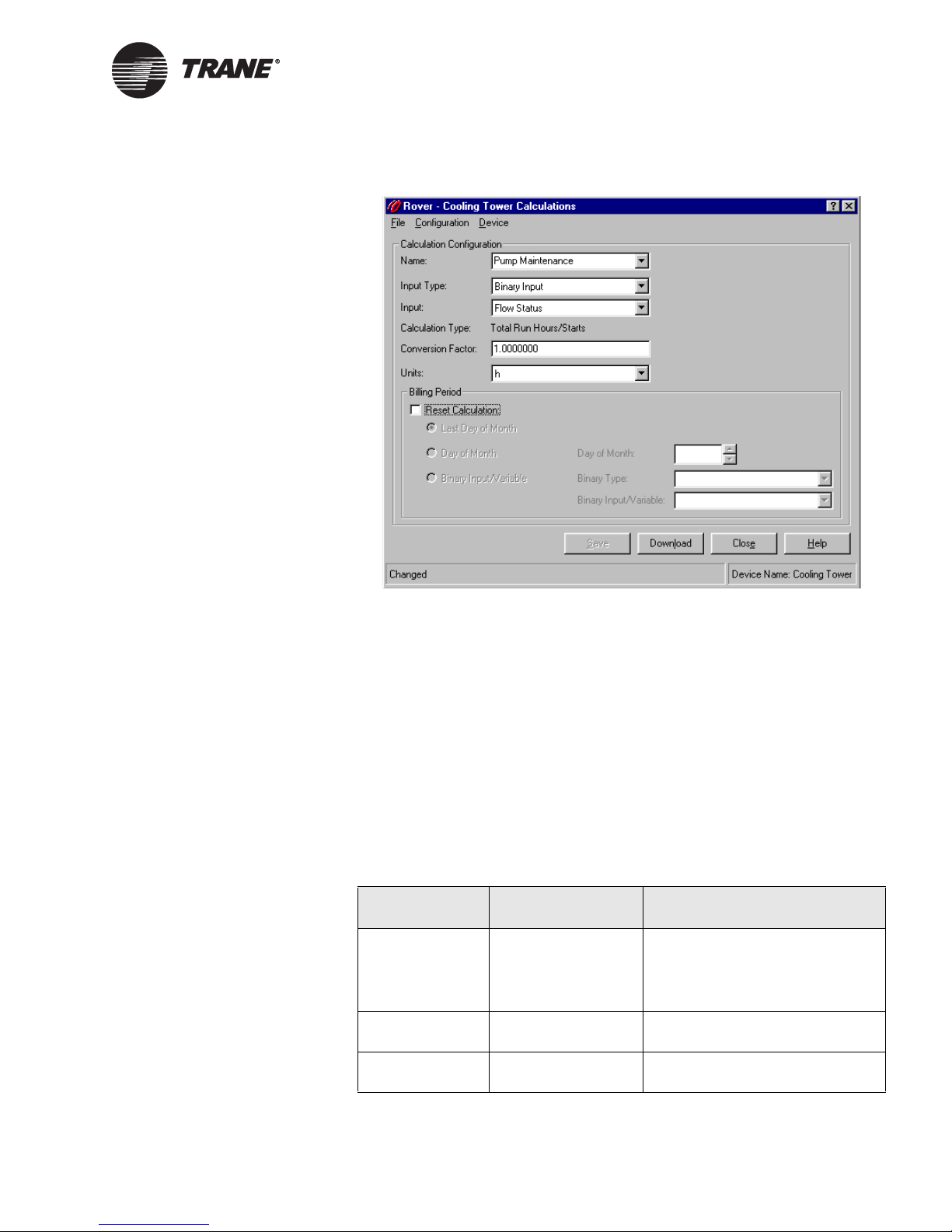
Figure 42. Calculations dialog box
Setting up a calculation
2. In the Name list, click the calculation you want to set up. The configuration information for that calculation appears.
3. If you want to change the calculation name, highlight the text and
type a new name.
4. In the Input Type list, click the type of input you want the calculation
to use.
This selection also controls what type of calculation occurs. If you
select either an analog input or pulse input, the calculation type is a
totalization. If you choose a binary input, Tracer Summit binary variable, local binary variable, or network variable input, the calculation
type is total run hours and starts. See Table 3 for a list of the input
types and their corresponding calculation types and available points.
Table 3. Input type selections
Input type Calculation type Available points
Analog input Totalization Universal inputs configured as
Linear (0–20 mA)
Universal inputs configured as
Linear (0–10 VDC)
Binary input Total run hours/
Starts
Pulse input Totalization Universal inputs configured as
Universal inputs configured as
Binary
Pulse
CNT-SVP01C-EN 67
Page 78

Chapter 5 Using the Calculations application
Table 3. Input type selections (Continued)
Input type Calculation type Available points
Tracer Summit
binary variable
Local binary
variable
Network variable
(nviSwitch)
Total run hours/
Starts
Total run hours/
Starts
Total run hours/
Starts
All Tracer Summit binary variables (1–30)
All local binary variables (1–120)
All generic network variables
nivSwitch01 to nviSwitch40
5. In the Input list, click the input you want to use in the calculation.
6. If the input is not a binary input, type a number in the Conversion
Factor field.
This value is used to convert the raw calculation into a more meaningful value. The default value is 1 and is good for many configurations. The conversion factor used here does not affect the value sent to
the Tracer Summit system. Click the Help button to see a table of
common conversion factors.
7. In the Units list, click the display units for the calculation output.
8. If you want to reset the current calculation values to zero at a specific
time or when an event occurs, click to select the Reset Calculation
check box and go to step 9. If you do not want to reset the calculation,
go to step 13.
Resetting the calculation moves the current-period value to the lastperiod value and sets the today, yesterday, and current-period value to
zero.
9. Click the option for the time you want the calculation reset.
• If you want the calculation reset at 12:00 A.M. on the day after the
last day of the month, click the Last Day of Month option and go
to step 13. The value just before the reset is saved as the lastperiod value.
• If you want the calculation reset at 12:00 A.M. the day after a
defined day of the month, click the Day of Month option and go to
step 10.
• If you want the calculation reset when a binary point changes
from off to on, click the Binary Input/Variable option and go to
step 11.
10. In the Day of Month list, click the day of the month you want the calculation reset and go to step 13. The calculation is reset to zero at
12:00
A.M. on the day after this day, and the value just before the reset
is saved as the last-period value.
68 CNT-SVP01C-EN
Page 79

Clearing a calculation
11. In the Binary Type list, click the type of binary point you want to control the calculation reset. See Table 4 for a list of the binary points
available for each input type.
The calculation restarts when the binary point changes back to off.
The value just before the reset is saved as the last-period value.
Table 4. Binary input types
Input type Available points
Binary input Universal inputs configured as binary
Tracer Summit binary variable All Tracer Summit binary variables (1–30)
Local binary variables All local binary variables (1–120)
Network variable All generic network variables nviSwitch01
to nviSwitch40
12. In the Binary Input/Variable list, click the binary input or variable
you want to control the calculation reset. The calculation is reset to
zero when this binary point changes from off to on, and the value just
before the reset is saved as the last-period value.
13. Complete one of the following options:
• Click another calculation name in the Name list to edit another
calculation.
• Click the Download button to download your changes to the
Tracer MP580/581 and click Close to close the Calculations dialog
box.
Clearing a calculation
Use the Clear Calculation button to manually set all calculation values
(today, current period, yesterday, and last period) to zero.
To clear a calculation:
1. In the Active Device view, click the Application tab. The status of the
applications appears.
2. In the Calculations table, click the name of the calculation you want
to reset.
3. Click the Clear Calculation button. A message appears asking if you
want to set the data to zero.
4. Click Yes. All the calculation values are set to zero.
5. Complete one of the following options:
• Click another calculation name in the Name list to edit another
calculation.
• Click the Download button to download your changes to the
Tracer MP580/581 and click Close to close the Calculations dialog
box.
CNT-SVP01C-EN 69
Page 80

Chapter 5 Using the Calculations application
70 CNT-SVP01C-EN
Page 81

Chapter 6
Graphical programming
overview
Use the Tracer graphical programming (TGP) editor to create and modify
programs for the Tracer MP580/581 controller. The programs are stored
in the controller with their graphical representations and can be
uploaded and modified or re-used.
This guide includes basic instructions to introduce you to the editor. The
TGP editor includes sample programs for common applications, such as
cooling towers and air handlers. For a step-by-step tutorial on how to use
the TGP editor, see the Tracer Graphical Programming applications
guide (CNT-APG001-EN).
Opening the TGP editor
To open the TGP editor:
X In the Active Device View, click the Program Editor button. The TGP
editor appears with a blank program in the design space (Figure 43
on page 72).
CNT-SVP01C-EN 71
Page 82

Chapter 6 Graphical programming overview
Figure 43. TGP editor running in Rover service tool
Title bar
Menu bar
To ol b a rs
Design
space
Splitter bar
Output
window
TGP editor
The TGP editor screen includes the design space, output display, blocks,
menu bar, toolbars, and shortcut menus.
Design space
The design space is the area in which you can draw graphical programs.
Output display
The output display is the area in which results from building a graphical
program appear.
To show or hide the output display:
72 CNT-SVP01C-EN
Page 83

TGP editor
X From the View menu, choose Output Display. If Output Display is
checked, the output display is shown.
Note:
If you still cannot see the output display, the splitter bar may be
too low. To move it up, make sure the status bar is visible and
click under the design space. Move the splitter bar up.
Blocks
Graphical programming blocks are the fundamental objects used to write
a program in the TGP editor. Each block serves a specific purpose. Connecting these blocks in a given arrangement determines how the program
behaves. A program consists of a combination of graphical programming
blocks connected to perform a logical task.
Figure 44 illustrates the basic structure of a graphical programming
block. The connection points on the left side of the block are called input
ports. Input ports pass data into the block. Connections on the right side
of the block are called output ports. Output ports pass data out of the
block.
Figure 44. Block structure
Note:
For further information on specific graphical programming
blocks, see the blocks reference in the online Help.
Menu bar
The menu bar at the top of the TGP editor contains drop-down menus for
working with TGP programs. Use the File menu to open new and existing
program files as well as to save programs and set program properties.
Use the Edit menu to undo and redo the last action made in the editor.
This menu also includes options for cutting, copying, pasting, and deleting program elements.
Use the View menu to set up the editor window. The Blocks menu
includes options for placing blocks in the design space. Use the Alignment
menu to align blocks in the design space. The Tools menu includes options
for working with your program. Use the Help menu to access the extensive TGP online Help and to find more information about the TGP editor.
CNT-SVP01C-EN 73
Toolbars
The TGP editor includes toolbars that provide buttons you can press to
complete common tasks.
Page 84

Chapter 6 Graphical programming overview
Standard toolbar
Use the Standard toolbar buttons (Figure 45) to open a new or existing
program file or to save a file. Click one of the edit buttons to cut, copy,
paste, or delete a block or group of blocks. You can undo or redo the last
action completed in the editor, add a wired or wireless connection, or print
the program. Click the Help button and then click on a block in the design
space to get information about that block.
Figure 45. Standard toolbar
New
Save
Open
Cut
Print
Paste
Copy
Redo
Undo
Select
Delete
Comment
Wire
Wireless
Connection
Help
Alignment toolbar
Select the blocks in the design space you want to align and click an alignment button (Figure 46) to align the blocks in the design space. The last
block selected controls the alignment.
Figure 46. Alignment toolbar
Right Alignment
Left Alignment
Top AlignmentTop Alignment
Bottom Alignment
74 CNT-SVP01C-EN
Page 85

TGP editor
Block toolbars
Use each of the following toolbars to add various blocks to your TGP program (Figure 47). For more information about each block, see the blocks
reference in the online Help. The blocks are subdivided into eight categories. These categories are displayed in separate toolbars.
Figure 47. Block toolbars
Math toolbar
Multiply
Average
Maximum
Add
Subtract
Input/Output toolbar
Network
Configuration Input
Network
Variable Input
Input
(Hardware)
Output
(Hardware)
Network
Variable Output
Logic toolbar
Compare toolbar
Greater
Than
Divide
Constant
Variable
Time
And
Less Than
Date
Not
Or
Minimum
Occupancy
Tr ac e r
Request
Equal
Square Root
Absolute Value
Comm Status
Calculation
Status
Output Status
Xor
Between
CNT-SVP01C-EN 75
Calculation toolbar
Greater Than
or Equal
Less Than
or Equal
PID
Dewpoint
Enthalpy
Not Equal
Air Flow
Air Flow
Wet-Bulb
Reset
Page 86

Chapter 6 Graphical programming overview
Function toolbar
Limit
Deadband
Switch
DeEnumerator
Time Delay toolbar
Delay on Stop
Latch
Delay on Start
Feedback Alarm
Test toolbar
Fail
On
Cancel
Program toolbar
Use the Program toolbar to build programs and to control the programs
on the Tracer MP580/581 controller (Figure 48).
Figure 48. Program toolbar
Upload from
MP580
Replace Existing -
Download to MP580
Build
Delete Program
New - Download
to MP580
from MP580
Showing or hiding toolbars
You can show or hide each toolbar in the TGP editor window. You can also
move each toolbar in the window by clicking on the title bar of the toolbar
and dragging it to a new position.
To show or hide a toolbar:
X From the View menu, choose Toolbars. From the Toolbars menu,
choose the toolbar you want to view or hide. If a check mark is next to
the toolbar name, that toolbar is shown in the window.
76 CNT-SVP01C-EN
Page 87

Keyboard short cuts
Short cut menus
To view a shortcut menu, use your right mouse button to click any block
or port in the design space (Figure 49). Shortcut menus contain common
commands you can use on the item you clicked. For example, right-click
an input (hardware) block in the design space and choose Properties from
the shortcut menu to edit the properties of the block.
Figure 49. Shortcut menu
Keyboard short cuts
Use keyboard short cuts (Table 5) in the TGP editor to work with program
files and blocks.
Table 5. Keyboard short cuts
Category Function Key stroke
File New Ctrl+N
Open Ctrl+O
Save Ctrl+S
Print Ctrl+P
Edit Undo Ctrl+Z
Redo Ctrl+Y
Cut Ctrl+X
Copy Ctrl+C
Paste Ctrl+V
Delete Delete
Blocks Block (pop-up menu) Ctrl+B
Comment Ctrl+T
Wire Ctrl+W
Wireless Ctrl+L
Program Build F7
Tools Start Debug/Start
Simulation
Run F5
Exit Debug/Exit
Simulation
F11
Shift+F11
CNT-SVP01C-EN 77
Page 88

Chapter 6 Graphical programming overview
78 CNT-SVP01C-EN
Page 89

Chapter 7
Creating a graphical program
This chapter introduces the basics of Tracer graphical programming
(TGP). Graphical programming consists of drawing a picture that represents data and logic.
Before you start to write a program, configure the inputs and outputs. For
more information on configuring the inputs and outputs, see Chapter 3,
“Configuring the Tracer MP580/581.” For more information on setting up
the wiring, see the Tracer MP581 Programmable Controller Hardware
Installation guide (CNT-SVN01B-EN).
Creating a new program
When the editor opens, a new, blank program appears. If a program is
already open, or you want to open a new program, save the current program and then choose New from the File menu. A blank program appears
in the design space (Figure 43 on page 72).
Note:
Only one program can be open in the TGP editor at a time.
Opening an existing program
To open an existing program:
1. From the File menu, choose Open. The Open dialog box appears.
2. Select the program you want to open.
3. Click Open. The program opens in the design space (Figure 50).
Figure 50. Equipment room exhaust fan program
CNT-SVP01C-EN 79
Page 90

Chapter 7 Creating a graphical program
Editing program properties
The next step in writing a graphical program is to give the program a
name and define some basic properties of the program. The properties of
a program define how the program behaves. For example, Run Frequency
is a property that defines how often the program executes. It is good practice to set the program properties before you begin to write a new program, but you can edit the properties at any time by opening the Program
Properties dialog box.
To select the appropriate method of program execution, ask yourself the
following questions:
• Is the program required to run at regular time intervals? If so, click
the Run Frequency option. Then specify the time interval in hours,
minutes, and seconds.
• Is the program required to run on demand? If so, use the Event Trig-
ger option to provide the program with a reference to a universal
input configured as a binary input or to a binary variable. When the
binary input or variable changes state, the program runs.
• Is the program required to run only when the Tracer MP580/581 pow-
ers on? In this case, click the Start-up option.
To edit program properties:
1. From the File menu, choose Program Properties. The Program Properties dialog box appears (Figure 51 on page 81).
80 CNT-SVP01C-EN
Page 91
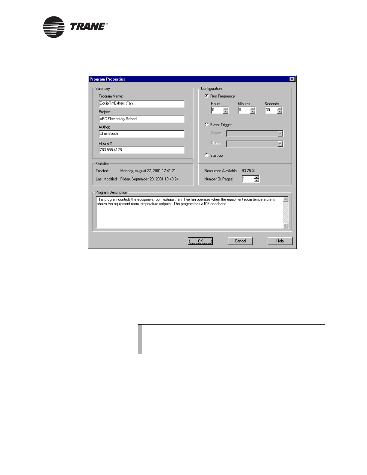
Figure 51. Program Properties dialog box
Editing program properties
2. In the Program Name field, type a name for your program.
The name may be up to 32 characters in length. Do not use spaces or
special characters except for an underscore in program names.
3. Type your name, project name, and phone number in the appropriate
fields.
This information appears on the printout of the program.
4. Under Configuration, click one of the Run Frequency options.
Note:
When choosing Run Frequency, keep in mind that universal
input status from expansion modules is updated every
2 seconds.
5. In the Number of Pages field, type the number of pages you need to
draw your program.
The allowable range is one to five pages. You can always change the
number if you find that you have too few or too many pages.
6. In the Program Description field, type a description of your program.
7. Click OK.
CNT-SVP01C-EN 81
Page 92
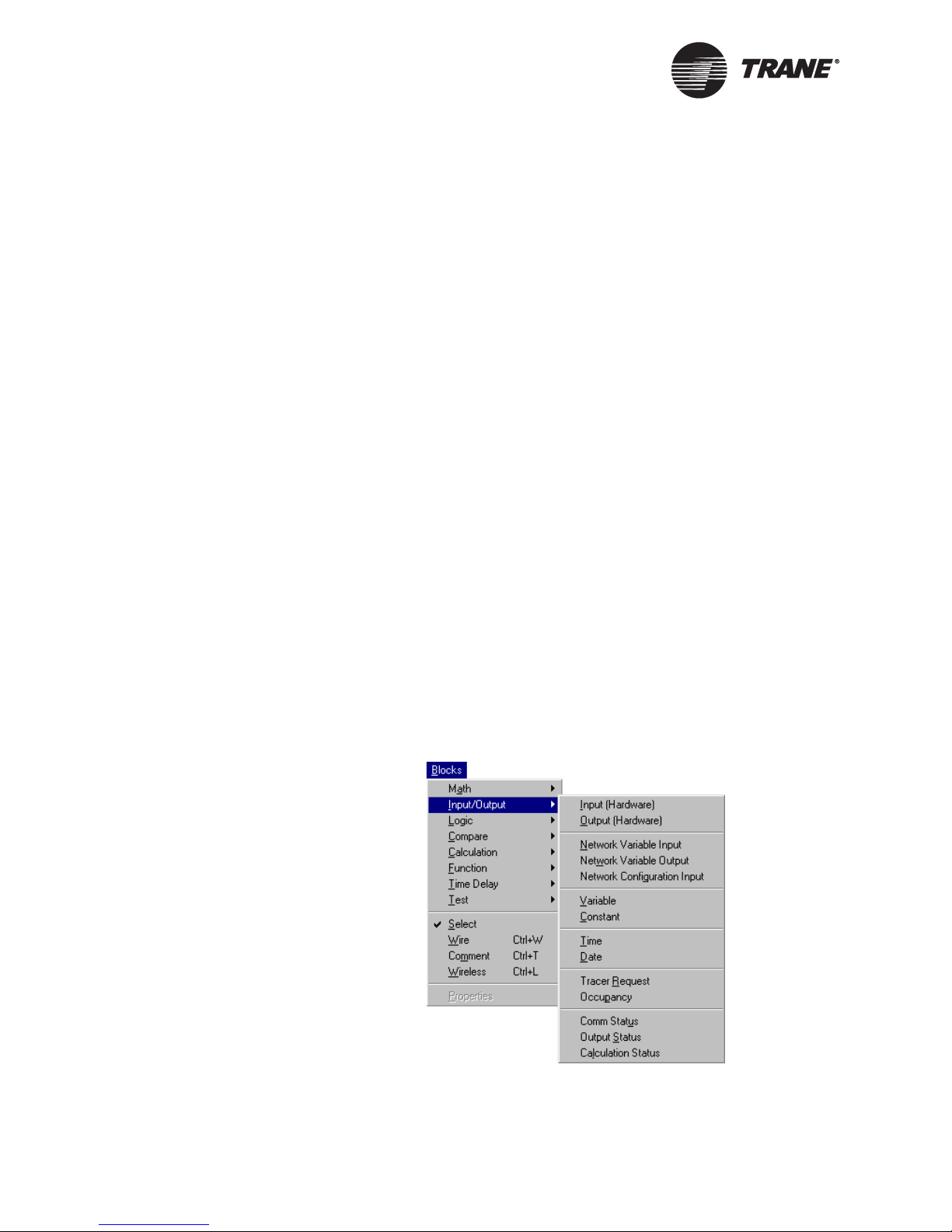
Chapter 7 Creating a graphical program
Setting page width and size
The page size and layout you choose impacts the design space. For example, if you want to have a wider and shorter space, choose the landscape
option. If you want to print your programs on 11 × 17 in. paper, choose
that option.
To set page width and size:
1. From the File menu, choose Page Setup. The Page Setup dialog box
appears.
2. Set the paper size, orientation, and margins. These settings apply to
the TGP editor design space.
3. Click the Print Setup button. The Print Setup dialog box appears.
4. Set the paper size and orientation to implement these settings on
paper when the program is printed.
5. Click OK. The Print Setup dialog box closes.
6. Click OK. The Page Setup dialog box closes, and the design space
changes to the new setting.
Adding a block
To add a block:
1. From the Blocks menu, choose the type of block you want to add. See
Figure 52 for an example. The cursor changes to a cross-hair (;) when
over the design space.
Figure 52. Choosing Input (Hardware) from the Input/Output Blocks
menu
82 CNT-SVP01C-EN
Page 93

Editing block properties
2. Click in the design space to place the block. The block appears at the
cursor location in the design space (Figure 53).
Figure 53. Input (Hardware) block
Editing block properties
A block is an object. In the TGP editor, you can edit the properties for
objects, such as programs and blocks, by using their properties dialog
boxes. Set the properties of each block as you place it in the program. This
is especially important for blocks that can be set as analog or binary,
because the connections between blocks are dependent on the data type,
analog or binary.
To edit block properties:
1. Click on the block to select it. The block is outlined in yellow.
2. From the Edit menu, choose Properties. The properties dialog box for
the block appears (Figure 54).
Note:
The properties dialog boxes for each block vary considerably
depending on the options available for that block. Some blocks
have no editable properties.
Figure 54. Input Properties dialog box
3. Set the properties for the block.
4. Click OK.
CNT-SVP01C-EN 83
Page 94

Chapter 7 Creating a graphical program
Adding a comment
Use comments to make notes in your program, to annotate blocks, or to
describe logic.
To add a comment:
1. From the Blocks menu, choose Comment and click in the design space
to place the Comment block. The Comment dialog box appears.
2. Type the text you want to appear as a comment.
3. Click OK. The comment appears in the design space (Figure 55).
Figure 55. Comments added to describe the Constant block and the Deadband block
Comments
Arranging blocks
The graphical element of graphical programming is critical. Move blocks
and use the alignment options to arrange your blocks and design your
programs.
Moving blocks
To move blocks:
1. Press and hold the left mouse button on a block and then move the
cursor (click and drag) to move the block to a new position in the
design space. The block appears in the new location.
2. To select two or more blocks, press the Ctrl key while clicking to select
blocks. The selected blocks are outlined in yellow.
Note:
You can also use a rubber-band selection to select more than
one block. Click in the design space and drag the cursor so that
the white line surrounds the blocks you want to select.
3. Click and drag the selected blocks to a new position in the design
space. The blocks appear in the new location.
84 CNT-SVP01C-EN
Page 95

Deleting a block
Aligning blocks
To align blocks:
1. Select two or more blocks. The last block selected is the controlling
block, so all of the selected blocks align according to the position of the
last block selected. The selected blocks are outlined in yellow.
2. From the Alignment menu, choose the alignment you want. The
blocks align according to the selection.
Deleting a block
To delete a block:
1. Click on the block. The block is outlined in yellow.
2. From the Edit menu, choose Delete. The block and any wires connected to the block are removed from the design space.
Note:
To delete a block, you can also select the block and then press
the Delete key.
Connecting blocks using wired
connections
To use wired connections to pass data from block to block:
1. From the Blocks menu, choose Wire. The cursor changes to a crosshair (;) in the design space.
2. Hold the cursor over the output port of a block. The cursor changes
from a simple cross-hair to a cross-hair with a square (Figure 56).
This change in the cursor indicates that a connection may be made.
Note:
You may start wires on any block-input or -output port or on an
existing wire. You cannot end a connection on a wire.
Figure 56. Cursor in wire mode over a valid connection
CNT-SVP01C-EN 85
Page 96

Chapter 7 Creating a graphical program
3. Click on the output port of a block. A solid or dotted line appears
between the connection point and the cursor.
Note:
A solid wire between blocks represents analog data being
passed. A dotted wire between blocks represents binary data
being passed. An analog-output port cannot be connected to a
binary-input port, and a binary-output port cannot be connected to an analog-input port. Figure 57 shows the cursor that
is displayed over an invalid connection.
Figure 57. Cursor in wire mode on an invalid connection
4. Click in an empty area of the design space to add a turn to the wire.
5. Move the cursor and click on an input port of a block. The wired connection is complete (Figure 58).
Figure 58. Analog wired connection
Connecting blocks using wireless
connections
Use wireless connections to pass data from block to block when wired connections are impractical. In general, it is good programming practice to
use an input in a program only once. By doing so, you will have an easier
time debugging your program. By using the wireless connection, you can
also prevent long and overlapping wired connections that are difficult to
follow.
Figure 59 on page 87 is a sample program without wireless connections.
Figure 60 on page 88 is the same program with two wireless connections
added.
Analog
wire
Binary
wire
86 CNT-SVP01C-EN
Page 97

Figure 59. Program without wireless connections
Connecting blocks using wireless connections
CNT-SVP01C-EN 87
Page 98

Chapter 7 Creating a graphical program
Figure 60. Program with wireless connections
To connect blocks using a wireless connection:
1. From the Blocks menu, choose Wireless. The cursor changes to a
cross-hair (;) in the design space.
2. Click in the design space to place a wireless block. The Wireless Connection Properties dialog box appears (Figure 61 on page 89).
88 CNT-SVP01C-EN
Page 99

Connecting blocks using wireless connections
Figure 61. Creating wireless connection block
3. Under Block, click the Write (Create) option to create a new wireless
connection block.
4. Under Create, click the option for the type of connection you want to
make: analog or binary.
5. In the Name field, type a name for the block.
The name may be up to 16 characters in length. Spaces are not
allowed.
6. Click OK. The Wireless write block appears in the design space.
7. Connect the Wireless write block with a wired connection to the block
with the value you want to write to the wireless block (Figure 62).
Figure 62. Wireless write connection
8. From the Blocks menu, choose Wireless. and click in the design space
to place a wireless block. The Wireless Connection Properties dialog
box appears (Figure 63 on page 90).
CNT-SVP01C-EN 89
Page 100

Chapter 7 Creating a graphical program
Figure 63. Using wireless connection block
9. Under Block, click the Read (Use) option to use a new wireless connection block.
10. Under Use, in the Name list, click the wireless connection you want to
use.
11. Click OK. The Wireless read block appears in the design space.
12. Connect the Wireless read block with a wired connection to the block
to which you want to pass the wireless value. The wireless connection
is complete (Figure 64).
Figure 64. Wireless read connection
90 CNT-SVP01C-EN
 Loading...