

Page 1
Operations Guide
Home Standby Generator
o TR15REG-DB (15Kw single-phase)
o TR20REG-DB (20Kw single-phase)
o TR20REG-DB-3 (20Kw three-phase)
Note: “Graphics in this document are for representation only.
March 2017 032-5095-1A-EN
Actual model may differ in appearance.”
Page 2
Operations Manual
For licensed authorized personnel only.
o TR15REG-DB o TR20REG-DB o TR20REG-DB-3
Read all instructions carefully before installation
WARNING: Only qualied technicians and contractors
are to perform installation
NOT INTENDED FOR USE IN CRITICAL LIFE
SUPPORT APPLICATIONS!
Save all instructions!
It is recommended that the Serial Number # be recorded for future warranty, parts and service needs. It can be
located, inside the back-panel on the stamped ID plate or on the outside of original shipping carton. This sys-
tem requires a password to unlock controller for operation and programming. Call 844-367-5660 for password.
Engine ID # __________________________________________
Controller Password ___________________________________
2
032-5095-1A-EN
Page 3

Table Of Contents
Preface . . . . . . . . . . . . . . . . . . . . . . . . . . . . . . . . . . . . . . . . . . . . . . . . . 4
Danger and Warning Labels . . . . . . . . . . . . . . . . . . . . . . . . . . . . . . . . . . . . . 5
Chapter 1: Technical Features 8
Technical Features of your Generator 8
Specications 9
Chapter 2: Important Safety Instructions 10
Fuel System 11
Servicing the Exhaust System 11
Servicing the Engine 11
Grounding Electrical Equipment 11
Gas Vapors and Fuel Leaks 12
Engine Noise 12
Short Circuits 12
Moving Parts 13
Operating System Functions and Denitions . . . . . . . . . . . . . . . . . . . . . . . . . . . . . . . . . 13
Engine Prestart & Preparations . . . . . . . . . . . . . . . . . . . . . . . . . . . . . . . . . 15
Chapter 3: Long Term Care & Storage of Generator 20
Chapter 4: Maintenance of Generator 21
Engine Oil 22
Replacement of Old Engine Oil 22
Replacement of Oil Filter 23
Maintenance of Cooling System 24
Routine Radiator Maintenance 25
Routine Belt Inspection 25
Chapter 5: Specications 26
Basic Dimensions 28
Control Features 29
Emission System and Maintenance 32
Warranty Information . . . . . . . . . . . . . . . . . . . . . . . . . . . . . . . . . . . . . . . . . . . . . . . . 34
032-5095-1A-EN
3
Page 4
PREFACE
Thank you for purchasing this high performance, liquid-cooled, automobile engine-driven generator.
This generator set is designed for use in stationary (permanent) applications where unreliable utility
power may occur. Keep and read this manual carefully and follow all safety precautions and procedures
in this manual to ensure proper equipment operation and to avoid bodily injury or property damage.
Operating instructions presented in this manual assume that the standby electric and gas system has
been installed by an authorized Service dealer or licensed and qualied contractor.
This is not a “Do-It-Yourself” (DIY) project!
ATTENTION! Follow all safety precautions and instructions as outlined in this manual in its entirety.
If any portion of this manual is not completely understood, please contact an authorized service dealer
near you for installation, starting, operating and servicing procedures or, contact us at 844-367-5660.
Common sense and strict compliance with these special instructions while performing service are es-
sential to preventing accidents.
For professional advice on this product and its operating requirements, please contact a dealer near
you or contact us directly at the information provided below. If you have any questions or sugges-
tions, please contact us any time between 8:00am and 5:00pm CST.
“Customer satisfaction is our mission”
Phone: 844-367-5660
www.lifanpowerusa.com
4
032-5095-1A-EN
Page 5
Warning Announcements
Because this generator can be used as a single fuel or multi-fuel unit, pay close attention to factory settings.
This unit can run on natural gas (NG) or propane (LPG). Please pay attention to all factory settings! Unit
comes already preset to one fuel or the other.
Before starting generator:
• Read the user manual carefully and operate generator according to factory recommendations.
• If you do not operate according to the instructions, it can cause personal injury or loss of life.
Danger and Warning Labels
Danger and Warning labels are provided to indicate the possibility of damage and personal injury when using
this generator. Pay attention to all labels closely. This information also indicates what kind of damage could be
experienced.
NOTE: If you don’t follow the operational requirements, it could result in damage to the engine or
related generator equipment.
CAUTION: If you don’t follow the instructions of the operating requirements, it could result in personal
injury or death.
032-5095-1A-EN
5
Page 6

WARNING
If you don’t adhere to all state and local codes or follow the instructions closely outlined in the operating
requirements, it could result in nes along with serious injury or loss of life. Manufacturer not responsible
for damage.
Users must operate in accordance with all state and local code requirements; otherwise it could damage the
engine and genset.
This manual contains the following International ISO Graphical Symbols:
6
032-5095-1A-EN
Page 7

NOTE
Save These Instructions – The manufacturer suggests that these rules for safe operation be copied
and posted in potential hazard areas. Safety should be stressed to all operators, potential
operators and service technicians for this equipment.
NOTE
Save These Instructions – This manual contains important instructions that should be followed
during installation and maintenance of the generator and battery.
How to Obtain Installation, Parts and Service
Contact us at
EQUIPSOURCE, LLC. D/B/A Lifan Power USA
2205 Industrial Park Road
Van Buren, Arkansas 72956
TEL: 844-367-5660
FAX:479-471-7466
www.lifanpowerusa.com
032-5095-1A-EN
7
Page 8
Chapter 1: Technical Features
I. Technical Features of the 15 and 20kW Single and Three-Phase, Dual-Fuel Generators
This gas generator is Dual-fuel and able to utilize both Natural Gas (NG) and Liquid Propane (LPG).
It is a versatile multi-fuel engine. Based on our standards, we have designed this unit to operate in
an environmentally safe and user friendly manner:
1. Speed Regulating System: This gas generator uses an internally designed electronic speed
control system, allowing for quick and easy adjustments to the engine speed that can be set to
specic speed ranges. This control system allows the engine to run more smoothly and respond
quickly to sudden increases or decreases in required engine speed and electrical output.
2. Silent Air In-take System: Extra-large air intake cross-sections in the housing enclosure ensures
ample air ow for the engine and air intake. This unique housing enclosure design leads to a
signicant reduction in operating noise.
3. Large Liquid Cooled Radiator and Reservoir: The use of an oversized radiator and coolant
reservoir, like those used in automobile engines, allows for additional radiator coil surface and
helps maintain a more ambient and stable engine temperature even in the hottest climates.
Utilizing this liquid cooled system adds to the life and long term operating dependability of your
liquid cooled gas generator investment.
4. Automatic Transfer Switch (ATS) and Function: Our Automatic Transfer Switches are specically
designed to work with our systems and have proprietary connections. The ATS is a critical
component of any emergency or standby power system. They are used for transferring essential
loads and electrical distribution from one power source to another automatically, without
personal involvement.
5. Intelligent Hazard Control System and Function: The Intelligent Hazard Control System warns
of dangerous conditions that exist to the engine or generator. This system continually checks and
monitors the unit’s operating conditions and will automatically shut down if a problem is
detected, to help avoid costly damage. This system uses a visual control panel that can be preset
according to the user’s needs.
8
032-5095-1A-EN
Page 9
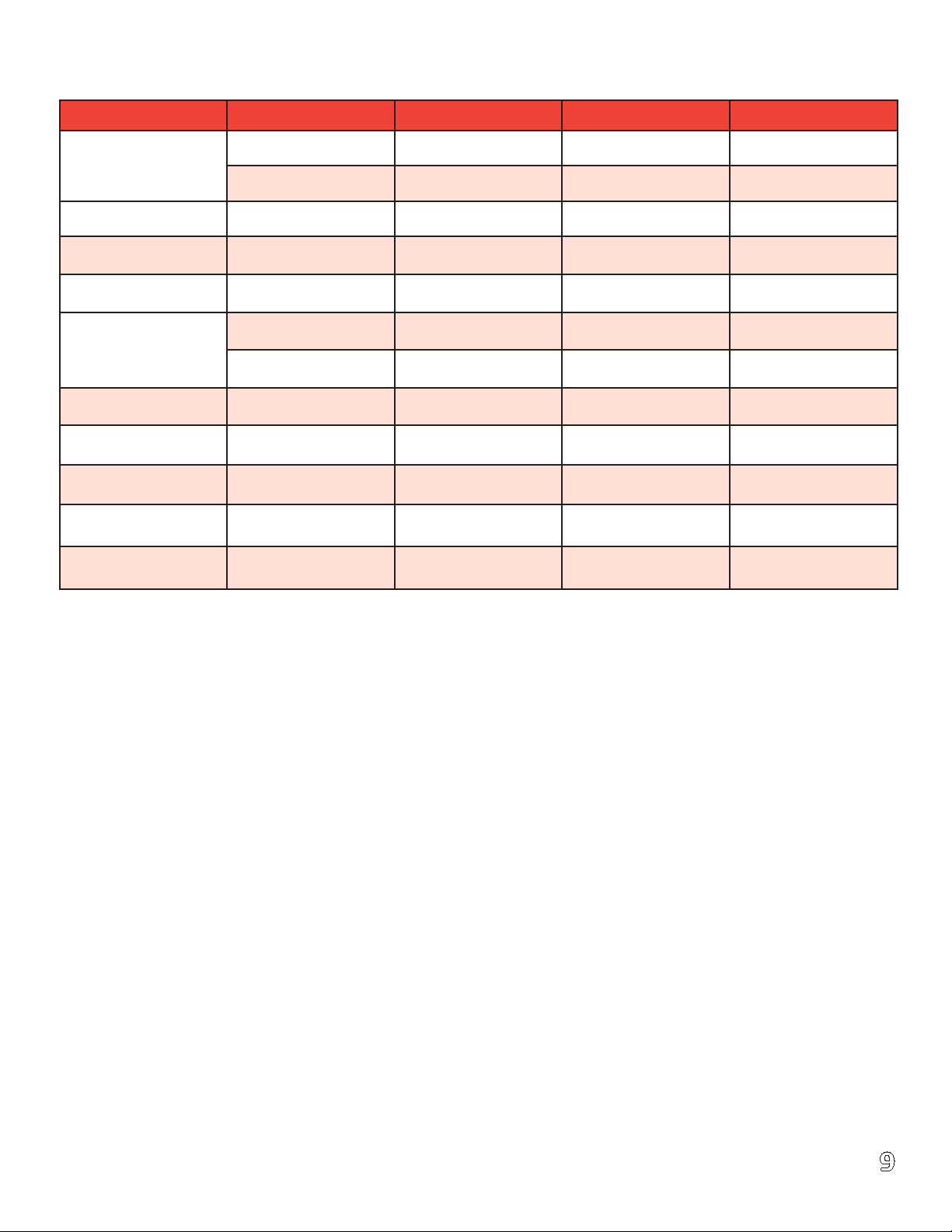
II. Specications - for more detailed specications see installation manual.
Item Unit TR15REG-DB TR20REG-DB TR20REG-DB-3
LPG 15 20 20
Rated Power (KW)
NG 15 18 18
Frequency (Hz) Hz 60 60 60
Speed (RPM) 3600 3600 3600
Rated Voltage (V) 120/240 120/240 120/208
LPG 62.5 83.3 69.5
Rated Current (A)
NG 62.5 75 62.5
Phase Single Single Three
Power Factor 1.0 1.0 .08
Protection Level IP 23 IP 23 IP 23
Insulation F F F
Pole 2 2 3
032-5095-1A-EN
9
Page 10
Chapter 2: Important Safety Instructions
SAVE THESE INSTRUCTIONS – This manual contains important instructions for the following models
TR15REG-DB, TR20REG-DB / TR20REG-DB3 that should be followed completely during installation and maintenance of the generator and battery.
I. Technical Features of the 15 and 20kW Single and Three-Phase, Dual-Fuel Generators
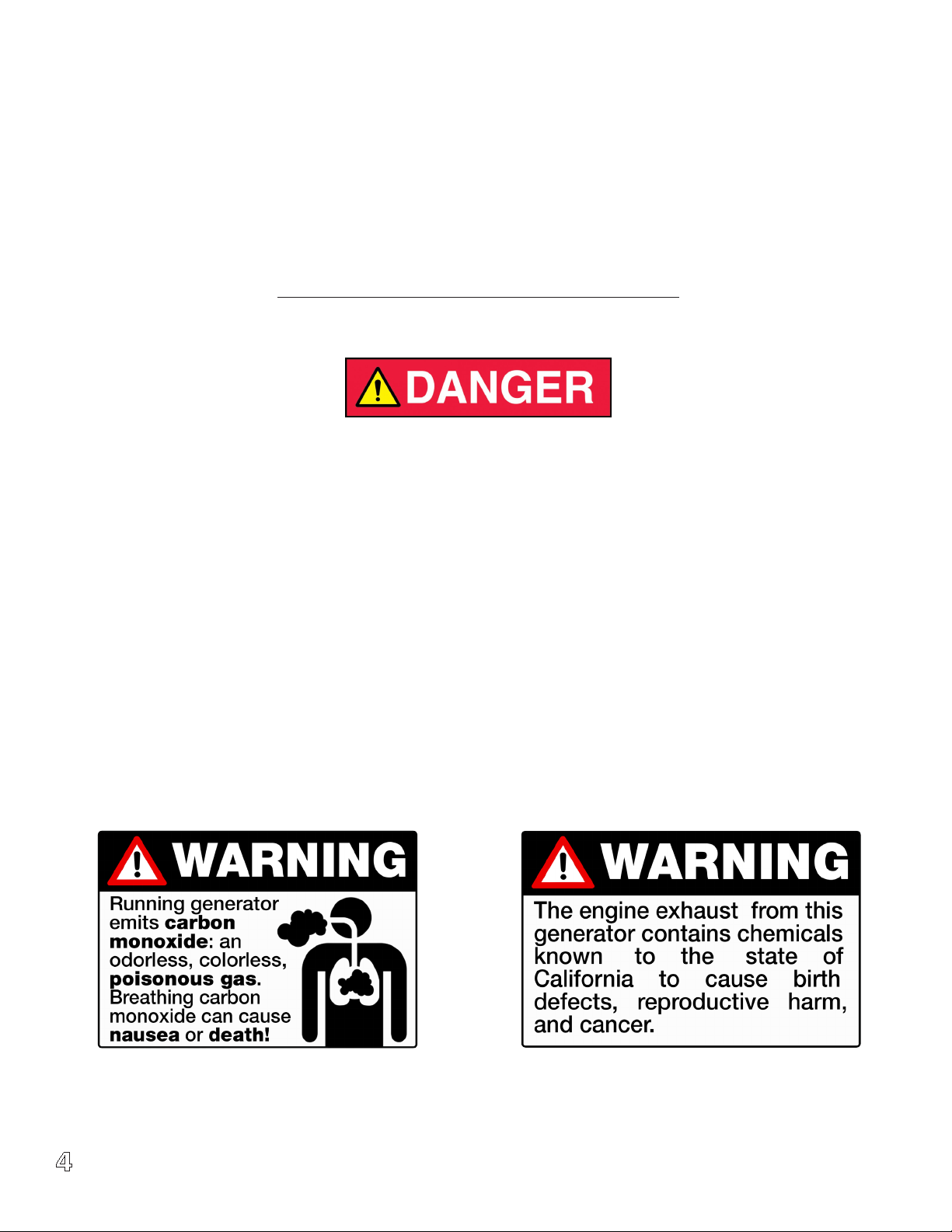
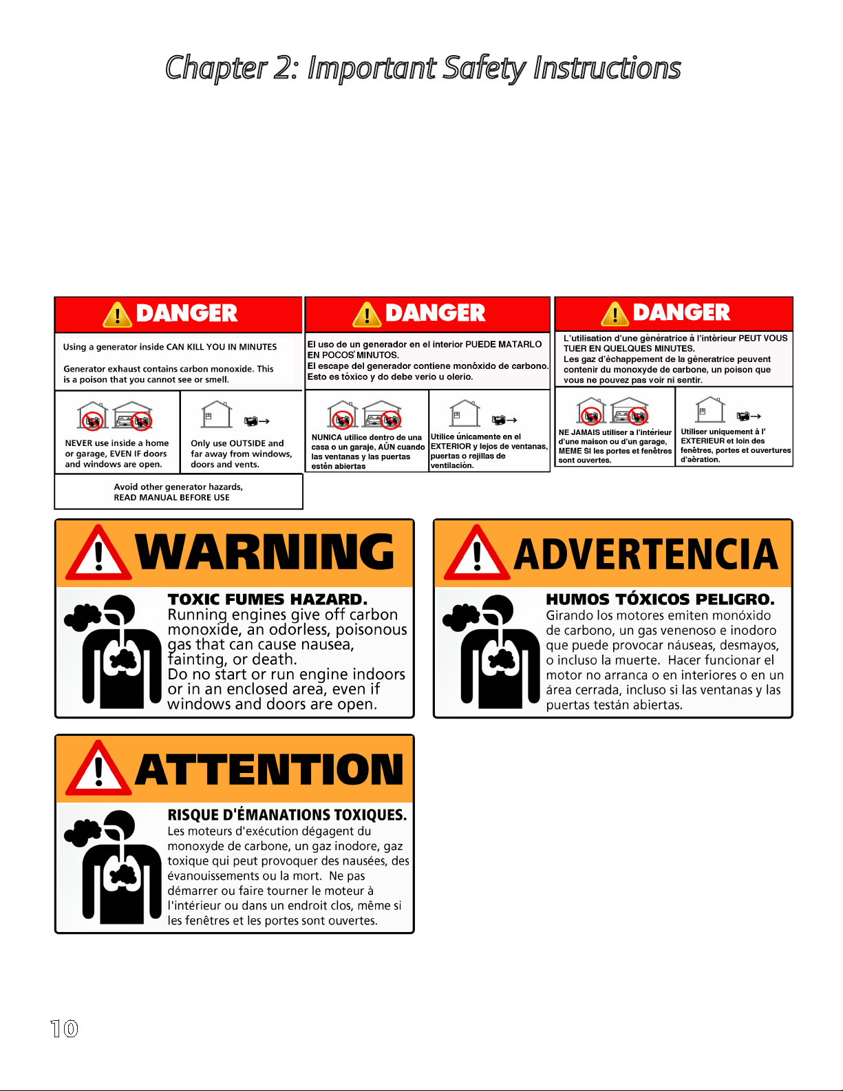
1. Generator set operation - Carbon monoxide can cause severe nausea, fainting, or even death. Carbon
monoxide is an odorless, colorless, tasteless, non-irritating gas that can cause death if inhaled for even a
short time. Avoid breathing exhaust fumes when working on or near the generator set. Never operate
the generator set inside a building. Never operate the generator set where exhaust gas could seep inside
or be drawn into a potentially occupied building through windows, air intake vents, or other openings.
10
032-5095-1A-EN
Page 11

2. Fuel System - Fuel Vapors are highly explosive and can cause severe injury or death. Use extreme care
when handling and storing fuels. Store fuels in a well-ventilated area away from spark-producing
equipment, gas hot water heaters and out of the reach of children. Never add fuel while the engine is
running or hot, fuel spills may ignite on contact with hot parts and mufer. Do not operate under the
inuence of drugs and alcohol or smoke. when operating around sparks or open ames. Keep fuel lines
and connections tight and in good working condition.
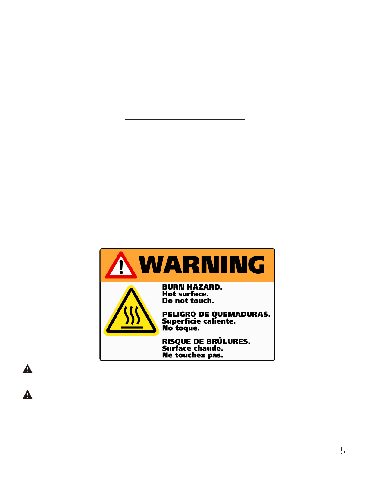
3. Servicing the exhaust system. Hot parts can cause severe injury. Do not touch hot engine parts. The
engine and exhaust system components become extremely hot during operation.
4. Servicing the engine. Hot parts can cause personal injury or property damage. Keep the generator at
least 2m (6ft) distance from other devices.
5. Grounding electrical equipment. Hazardous voltage can cause severe injury or
death. Electrocution is possible whenever electricity is present. Ensure you comply with
all applicable state and local codes and standards. Electrically ground the generator set,
transfer switch, and related equipment and electrical circuits. Turn off the main circuit
breakers of all power sources before servicing the equipment. Never contact electrical
leads or appliances when standing in water or on wet ground because these conditions
increase the risk of electrocution. It is highly recommended that a barrier exists between
you and the ground surface at all times. We recommend using a wooden pallet with
rubber mat on top to stand on while working or servicing the standby generator.
Grounding is required of all AC circuits, use terminal (identify terminal) for bonding this
circuit to the enclosure with a grounding rod (Not provided with unit). Ground the
enclosure to a grounding electrode in accordance with state and local code
requirements.
032-5095-1A-EN
11
Page 12

6. Gas vapors and fuel leaks. Explosive fuel vapors can cause severe injury or death. Fuel leaks can cause
an explosion. Use digital gas leak detector on all gas connections for no less than 1 minuet per
connection. Leak detector not included with generator. Contact Service provider.
7. Engine noise. Hazardous noise can cause hearing loss. Generator sets not equipped with
sound enclosures can produce noise levels greater than 105dB. Prolonged exposure to noise
levels greater than 85 dB can cause permanent hearing loss! Wear hearing protection at all
times when working near an operating generator set.
8. Short circuits. Hazardous voltage/current can cause severe injury or death. Short circuits can cause
bodily injury and/or equipment damage. Do not connect electrical contacts with tools or while wearing
jewelry when making adjustments or repairs. Remove all jewelry before servicing the equipment.
Electrical back-feed through the utility power supply can cause severe injury or death. You
must install a manual or automatic transfer switch on all standby power applications and installations. This
is to prevent the back feeding of electrical current through power lines causing re, severe injury or death
to utility personnel working on power lines.
12
032-5095-1A-EN
Page 13

9. Moving parts. When the generator set is in operation, the cooling fan is rotating. Do not open the
maintenance cover and make adjustment while generator is running. You must shut down the engine and
turn electrical breaker to the off position before maintenance or operation. Before restarting, close all
service panels.
10. CAUTION. FOR STANDBY ELECTRICAL OUTPUT, CONNECT GENERATOR TO SUITABLY RATED TRANSFER
SWITCH IN ACCORDANCE WITH THE CANADIAN ELECTRICAL CODE, PART I. THIS UNIT REQUIRES A
200amp TRANSFER SWITCH
11. THERE IS A PERMANENT CONDUCTOR BETWEEN THE GENERATOR (STATOR
WINDING) AND THE FRAME.
12. Keep top cover locked at all times with provided key. Keep key stored in a safe place
out of the reach of children. If key is lost please call 844-367-5660.
Operating System Functions and Denitions
Alarm
Data Check Up
Gens Normal
Indicator Data Check Down
Stop Indicator Close Gens
Stop
Manual Manual Auto Auto Start Set
Indicator Indicator
Power Switch Fuel Switch
032-5095-1A-EN
13
Page 14

Operating System Functions and Denitions
Power Switch: The power switch controls the entire generator set control system. If this switch is placed in
the OFF (O push in down mode) position, the internal electrical control circuit of the unit will not have
electrical power. When this switch is placed in the ON (I in the up mode) position, the control system can be
manually or automatically started with ATS.
Fuel switch: The fuel switch allows the fuel to ow to the engine when placed in the ON or ( I ) is in the up
position. Likewise, the switch turns the ow of fuel off to the engine when placed in the OFF (O) push down
position.
Emergency stop switch: If an emergency situation occurs, immediately press
the Emergency Stop Switch located on the right outside corner of the
standby cabinet. The unit will automatically shut down. Once the switch has
been depressed and the emergency situation has passed, to re-start the
generator unit, rotate clockwise 15° to pop out into the normal operating
position. When depressed, all generator control systems will immediately
shut down, including the engine and generator head. The Emergency Stop
Switch should be pressed immediately should any unexpected emergencies occur. Depressing this button will
help minimize dangerous damage to persons, pets, property, plants, or to the generator unit itself.
Primary Circuit Breaker (located on main control panel under generator lid): The primary
circuit breaker controls the ON/OFF functions of the generators electrical power output.
When this switch is in the up (ON) position, electrical power output will be produced and ow
normally. When this switch is placed in the down (OFF) position, electrical power output will
be broken, or turned off. However, as a safety function, when this switch is placed in the ON
position, the production of a too large of an electrical load or a short circuit due to faulty
operation, the switch will immediately and automatically switch to the OFF position in order to protect the
generator from damage. Should this occur, turn off the generator unit and correct the cause before restarting
and placing the circuit breaker in the ON position.
Use: When starting manually, always start the generator before placing the main circuit breaker in the ON
position. Likewise, when operating manually, place the circuit breaker in the OFF position before shutting the
generator down.
14
032-5095-1A-EN
Page 15

Engine Prestart & Preparation
All necessary installation and annual maintenance must be conducted and performed by an authorized licensed
TRANE® Standby specialist to prevent warranty violation. If end-user changes and maintains oil, air and coolant service, they must maintain log, receipts and take pictures of hour meter at the time of service for verication.
Before starting engine for the rst time, engine oil and radiator coolant must be added. An initial uid
inspection and pre-check is recommended before starting genset for the rst time or after unit has been in
operation for over 50 hours. It can also be used as a quick review of all uids. Check all of the following items
before running system for the rst time.
IMPORTANT NOTE! Unit is not shipped with engine oil or coolant from Factory!!
After installment of generator, ll engine with recommended oil weight based on ambient temperature shown
below and add radiator coolant. Prior to initial startup, replace all service panels and close lid. Start engine and
allow 10 minutes for system to warmup. After this has been performed, remove service panels, lift the lid, and
check for any leaks or drips. If found, tighten lose hoses, clamps or plugs. Recheck all uid levels and top off
as necessary.
1. Engine Oil. The unit is not shipped with oil from factory! Use high-quality synthetic motor oil “Classied
for Service with SAE viscosity ratings. Fill with the recommended amount of oil as specied. Overlling or under lling can cause damage to the engine. Only use the following recommended engine oil.
Temperature
Below 32° F (0° C) SAE 0W-40
32° to 80° F (-1° to 27° C) SAE 10W-40
Above 80° F (27° C) SAE 15W-50
• Place funnel in engine oil inlet.
• First time operation will require 4 liters or (4.25qts) of oil
• Check oil gauge dipstick regularly, oil level should be kept between top and bottom lines, at all
times. It is preferred to be at the top mark but not over.
Fuel Oil Level Mark
Mobil 1 Synthetic Oil or equivalent recommended
Engine Oil
032-5095-1A-EN
15
Page 16

2. Cooling System
Use only automotive grade antifreeze and distilled water in cooling system.
Do not use water that contains salt or alkalis (Tap Water)! Using non-distilled
water creates scale in the radiator, causing corrosion and premature wear.
You must check and maintain all fuel, lubricant and coolant levels. Not doing so will accelerate and shorten the
life of the standby system. Attention must be paid to all uid systems and annually serviced by an authorized
service provider or call 844-367-5660 for assistance.
Converting from Natural Gas (NG) to Liquid Propane Gas (LPG)
Most generators are congured for natural gas operation at the factory. Switching over to LP Vapor is a simple
procedure.
3. Fuel Conversion
Do not touch hot engine parts. The engine and exhaust system components
become extremely hot during operation.
Two fuel connections on the fuel block allow eld conversion between natural gas (NG) and Liquid Propane
(LPG). The fuel metering valves are factory-set and sealed to provide the best possible hot and cold starting.
Use the following procedure to convert fuel from type to another.
Natural Gas (NG) and Liquid Propane (LPG) Conversion.
• Use a pressure reducing valve to reduce LP pressure supply as needed.
• Push or pull the pin located above Regulator as pictured below, for desired fuel type.
LPG NG
A. Liquid propane (LPG)
For engines set up to run on Liquid propane, please check the fuel supply pressure, lower or higher
pressure range will result in equipment failure. Inlet pressure 1.7kPa to 3.5kPa, and gas line should be no
longer than 16 feet or 5 meters, the inner diameter shall not be less than (0.63”) or 16mm.
It is strictly prohibited to remove high pressure gas lines during operation,
service and repair. Contact your service provider. You must check and test for
gas leaks using a gas leak detector before use. The observation time is not
less than 1 minute per connection. Based on different gas sources that are available, there may be different
gas pressures present. Make sure pressure is known before installation. A pressure reducing valve may be required to obtain optimal requirements. You will need to use a pressure reducing valve if the pressure is excessively high. Additional parts and tools such as leak detectors and pressure gauges are not included with this
purchase.
16
032-5095-1A-EN
Page 17

B. Natural Gas (NG)
If the engine is set at the factory to run on natural gas, please check
the fuel pressure and ow. The purchase of a pressure reducing valve
might be required, and it is not included with this unit.
After installation please contact a service provider if user wants to switch fuel types from Natural Gas (NG) to
Liquid Propane Gas (LPG) or vice versa. Please contact the seller, installer or manufacturer at 844-367-5660.
4. Electrical Connections
If the generator set is used for standby power, install properly sized automatic transfer switch (ATS) provided
by manufacture. This will prevent inadvertent interruptions of standby power and normal sources of supply.
Always shut down generator before servicing the equipment. Never contact electrical leads or appliances when
standing in water or on wet ground because these conditions increase the risk of electrical shock.
5. Battery
Connect positive lead wire rst (+) and then negative lead wire (-) to
matching positive (+) and negative (-) terminals on battery. Connect
negative (-) lead last!
IMPORTANT! The generator will not start and circuit board damage can occur
if battery is connected in reverse.
(Before initial use the maintenance free battery should be tested for voltage, if >12.6V, it can be installed and
used immediately; After rst time use or <12.6V it should be re-charge before use.)
For rst time use, you should operate according to the steps below:
• Installing battery - take off red cap on positive battery terminal.
• Use a multi-meter to check voltage of battery before installing and starting. If reading is below 12.6V,
recharge battery.
• Connect positive terminal lead fully. Tighten terminal nut on battery lead and place red rubber cover over
terminal.
• Follow the same steps for negative or black battery lead, then place rubber cover over terminal.
Negative Positive
032-5095-1A-EN
17
Page 18

The battery represents a risk of high short circuit current. When working on the
battery, always remove watches, rings or other metal objects, and only use tools that
have insulated handles!
Installing, Servicing or Exchanging the Battery should be performed or supervised by knowledgeable
personnel. Battery connection or exchange requires precautions and protective gear. Always wear face and
eye protection with electrical rubber gloves, boots and battery apron. Keep unauthorized personnel away from
battery. When replacing battery, always use the same size battery and number type: 12V, Lead-acid battery.
CAUTION – Do not dispose of battery or batteries in a re. Batteries are capable of exploding.
CAUTION – Do not open or mutilate the battery. Released electrolytes have been known to be harmful to
skin, eyes and to be toxic.
CAUTION – A battery presents a risk of electrical shock and high short circuit current. The following
precautions are to be observed when working on batteries:
1. Remove watches, rings, or other metal objects.
2. Use tools with insulated handles.
3. Wear rubber gloves, apron, eye protection and boots.
4. Do not lay tools or metal parts on top of batteries.
Make sure the generator set is grounded. Check grounding strap to make sure the generator set ground terminal is securely grounded to a grounding rod.
6. Starting Generator
A. Turn on the power switch (on the left beneath the digital display).
B. Turn on the fuel switch (on the right beneath the digital display).
C. After 10 seconds, press the Manual Start button on the control panel.
D. Press the Auto Start button to initiate system start.
E. Press the Data Check Up and Data Check Down buttons to observe frequency, voltage, speed and the 12V
working voltage and operation time.
7. After the unit has started it will automatically sync with the ATS and enter into automatic mode. The
emergency stop switch, power switch and fuel switch must be kept in the ON position for automatic startup.
8. Inspection of generator set when operating.
Inspect the following systems when operating.
1. Radiator and Coolant level. After warmup, check the coolant ow in system by raising lid to make sure
coolant is circulating. If no coolant is visible owing through hose to coolant reservoir, shut down the
engine. Allow engine to cool down, and remove the radiator cap.
Checklist:
• Check for uid and coolant leaks
• Inspect inside and out of the radiator to ensure no excessive dirt is present.
• Check the radiator coils and ensure no dust, dirt or foreign debris exists.
• Check hoses to ensure they are not blocked.
Add additional coolant to recommended levels.
18
032-5095-1A-EN
Page 19

9. Fault indicator lamp
When red lamp indicator is illuminated, operator must shut the generator down and follow trouble
shooting guide and steps.
If the generator still won’t start, press the emergency stop switch. Rotate clockwise to pop up position. After
waiting for 30 seconds, try starting again. If generator still cannot be started, check the generator carefully for
loose wires, battery terminals and voltage output, gas ow to the lines and generator.
If, after restarting the generator, the fault indicator light is still red, the generator will automatically shut down.
Retrace steps in trouble shooting guide and procedures again. After correcting the fault, the generator is able
to be re-started. If the fault indicator light remains off, then the generator is operating normally. If not contact
your local service provider or contact us by calling 844-367-5660.
It is important to conrm after starting that the normal electrical output range is not exceeded as this will
damage the generator.
10. Exhaust color
As long as the generator engine is running within the rated output range,
A. The exhaust will be colorless.
B. If the exhaust is dark grey or black after running for 60 seconds or more, this is an indication of an
engine problem. Shut the engine down and contact your local service provider or contact us at
844-367-5660.
11. Other problems requiring shutting down of the generator
You should shut down the engine if the following circumstances happen.
• The engine speed is hunting (inconsistently speeding up and down)
• An abnormal noise is heard coming from the generator or engine.
• The engine exhaust suddenly turns dark grey or black.
• The fault indicating light is illuminated.
12. Shutting down the generator
Should a need occur to shut down the generator, shut down the electrical output rst by turning the circuit
breaker to the “OFF” position and depress the reset key. This will automatically shut the engine and generator
down.
The power switch (below the controller on the left) needs to be in the open or on position if connected to the
ATS system in order for the unit to start automatically.
032-5095-1A-EN
19
Page 20

Chapter 3: Long Term Care & Storage of Generator
Long term storage and care
1. Remove battery positive lead rst and then negative lead. Remove battery and store in dark dry place. It is
recommended to recharge it slowly every three months.
2. Turn Gas line to generator in off position and disconnect. Plug gas line with rubber plug to prevent dirt
from getting into gas line.
3. Remove all dirt from the generator if long time storage is needed.
4. Drain coolant from engine. Place drain pan under pre-plumed coolant line and open valve allowing all
coolant to drain (See page 26).
5. Drain oil from engine. Place drain pan under pre-plumed oil line and open valve allowing all oil to drain
(See page 26).
6. Ensure engine is in good technical condition, keep all surfaces clean.
7. Remove all spark plugs, pour 1oz or 30grams of engine oil in each sparkplug opening, turn crankshaft 20
turns slowly to allow oil to coat inside of cylinders and pistons, and then reinstall spark plugs.
8. Use dewatering Vaseline (heat range 100°-200°F) wipe on the surface of contacts.
9. Add light amount of penetrant oil to all, hinges, bolts and moving parts.
10. Use clean canvas or cloth to cover the engine and keep it dust-free.
11. Store and cover in a warm clean room with temperatures above (5°C, 41°F) relative humidity should be
kept between 40-70%.
12. Check for loose nuts, bolts and screws.
13. Seal gas line inlet valve with rubber plug to keep gas line free of dust.
14. Push the emergency stop button.
15. Cover the generator with the dustproof cover, and keep it in the dry and clean place;
16. Keep it in well ventilated, dry rainproof area and away from ammable and explosive materials
Starting after long periods of storage
1. Wipe and remove protective lubricants from all contacts
2. Remove spark plugs one at a time to remove 1oz or 30grams of engine oil from cylinders. Use clean rag and
place it in each spark plug opening and turn engine over slowly allowing oil to soak into clean rag. Repeat
this process for each cylender
3. Add light penetrant oil to all hinges.
4. Add coolant.
5. Add engine oil.
6. Check all wires and hose connections.
7. Install battery connecting positive lead rst and then negative lead
8. Reconnect gas line and check for leaks using a digital gas detector.
9. Start engine to make sure operation is normal.
10. If belts are making noise, shut down generator, allow to cool down and then tighten belts as needed
11. Check all electrical parts and digital display for normal working conditions.
12. If red indicator light on display panel is illuminated, perform trouble shooting procedures. See trouble
shooting guide.
20
032-5095-1A-EN
Page 21

Chapter 4: Maintenance of Generator
Regular maintenance is an important part of your investment and provides longevity of the complete generator system. Keep it in good working condition according to the specications outlined and it will provide many
years of dependable service.
The following generator maintenance specications are based on a good working environment. If working conditions are less than desirable (such as excessive dust, dirt and humidity, etc.) the maintenance interval periods
should be shortened.
When maintaining the generator set, you should operate in strict accordance with the following requirements.
Improper use and operation can cause premature failure.
Breaking-in period of New Engine
The life of the engine is greatly determined by the state of the rst cycle of use. It is recommended that the
oil be replaced after only 30 hours of use on the rst cycle. The new engine should be operated as required.
Abnormal engine wear will directly affect the life of generator engine.
Maintenance of the Fuel System
The genset is multi-fuel and comes preset from the factory to ether Natural Gas (NG) or Liquid Propane (LPG),
Maintenance will vary according to the fuel used.
Fuel is ammable and an explosive material. Smoking is prohibited while
working or servicing generator.
When using Natural Gas (NG) or Liquid Propane (LPG)
• Before each operation, you should check all components for loose connections. Check for uid leaks
around cylinders, pipes and hoses. Tighten as needed.
• Periodically check the gas pressure reducer and the solenoid valve sealing pad for deformities.
• Periodically check the low-pressure gas line to see if it has weathered or aged (soapy water can be used to
detect leaks).
• When maintenance of the gas line is required, gas valve must be closed before any maintenance or repairs
are carried out.
032-5095-1A-EN
21
Page 22

Maintenance of the Lubricating System
1. Engine oil
Oil viscosity: Select the viscosity according to your ambient temperature.
Oil quality level (according to standards set by the American Petroleum Institute): SE or higher-level oil.
After 30 hours of running new engine, preform rst oil change. Maintain and replace the amount of oil
according to the requirements (4qrts), this will ensure long dependable engine life. Only use full synthetic
motor oils, Mobil 1, 0W-40 is highly recommended or equivalent.
Do not mix different grades and detergents of oil.
2. Replacement of old engine oil
Replacing engine oil: This unit comes with drain hoses already installed from the factory for ease of service.
• Start the engine for 10 minutes to increase the temperature of the engine oil and allow better ow, then
stop the engine.
• Remove front panel on generator and place pan under the oil drain hose. Open oil drain valve to drain out
all engine oil. Use 10mm allan wrench included.
• Close oil drain valve and replace with recommended oil amount.
• Start engine and allow new oil to circulate and ll oil lter for three minutes. Make sure there are no
visible oil leaks!
• Shut down unit and top off oil as needed. Oil level should be between A and B marks on the dipstick, it is
preferred that the level be close to B mark but not over!
Water Drain Pipe Oil Drain Pipe
22
032-5095-1A-EN
Page 23

3. Replacement of used oil lter with new oil lter
Replace old oil lter after the engine has cooled. The replacement cycle should be followed according to the
maintenance cycle schedule.
Steps for replacement:
• Use oil lter wrench to remove old oil lter. Turn to the left to loosen.
• Before installing new oil lter coat, gasket surface with a thin layer of oil before installation.
• Twist new lter to the right to tighten into place with a rm hand. Do not over or under tighten lter
• Start generator and run for several minutes. Check for leaks. Shut down unit and check oil level using
dipstick. Oil level should read between point A and point B on dipstick. If needed add additional oil. Do
not over ll.
Note: Use oil lter wrench if needed but don’t over tighten, the recommended torque is between
15N.M-20N.M. Dispose of used oil and lter properly: do not pour down drain or on ground.
Direction A: Tighten Direction B: Loosen
032-5095-1A-EN
23
Page 24

Maintenance of the cooling system
When the engine is operating, there must be enough antifreeze and distilled water in the radiator system to
insure proper engine cooling. It is suggested to check it regularly before use, if there is not enough antifreeze
or distilled water add as needed. Do not use mineral, hard water or poor quality antifreeze. We suggest
Prestone, Shell, Texaco or similar brand.
1. Replace antifreeze and distilled water as outlined in the service guide or if discolored to a brown watery mix.
Combine antifreeze and distilled water only to manufactures suggested guidelines.
Do not replace cooling liquid when the engine is hot.
After prolonged use or time, the coolant can go bad and discolor. Follow the recommended steps as outlined
below;
• Place pan under pre-plumed coolant or water line pipe. See photo above.
• Open coolant or water line pipe valve and allow it to drain completely.
• Remove or wipe any old excess water.
• Close coolant or water drain pipe line valve.
• Rell radiator cooling system and reservoir until full.
• Start the generator without load for a few minutes. Allow for air pockets in the system to settle. Shut
down generator and add additional coolant as needed until the level remains steady.
• Shut down generator again and add coolant to the “FULL” level mark
• Make sure the expansion tank is lled half way between low and full mark.
• Install radiator cap and expansion tank cover. Inspect system carefully to make sure there are no leaks.
Hard water, mineral water and saline water is harmful to the engine and cooling system.
Do Not Use!
24
032-5095-1A-EN
Page 25

1. Routine Radiator Maintenance tips
• Regularly check radiator hoses. Inspect clamps and make sure they are secure.
• If hoses become deformed, develop bulges, hardening or cracking is visible, they need to be changed
immediately!
• Inspect and clean the cooling ns on the radiator regularly, use compressed air to blow out excess dust
and dirt. Important! Blow compressed air from the inside out. Debris can build over time and affect the
cooling system.
2. Routine Belt inspection tips
Adjust and replace timing belt and water pump belt as needed. Inspect them regularly for cracking or missing
pieces of rubber. Timing belt needs replacement every 1,000 hours of use! Water pump belt is extremely
important. It drives the water pump that cools the engine and entire system.
Note: Listen for sounds coming from the belts. If you hear the belts squealing when the generator starts
up, this is a sign that the belts are loose or worn and the system will run hot! If belts show signs of cracks
or pieces of belt are missing, contact service provider.
Important! To check to see if the belt is too tight make sure the main power
switch is in the off position.
Perform the following inspections and adjust or replace belt as needed.
Deection check of the belt:
7~10mm (0.28-0.35in) ∕ 100N {10.01kgf (22.1 lbs.)
Adjust the deected belt:
• Stop the engine.
• Use thumb to press on the belt between pulley wheels.
• If the tightness is not correct, adjust it by relaxing the tension wheel to the acceptable degree.
• Replace the water pump belt when it is cracked, missing pieces of rubber or singes of considerable wear.
032-5095-1A-EN
25
Page 26

Chapter 5: Specications
TRANE 15kW, 20kW and 20kW-3-phase standby generators
• Basic Dimensions
• Control Features
• Liquid Propane - LPG/ Natural Gas – NG
• Low Noise Level
• High-performance lubrication system
• Optional Items sold separately:
Cold and Extreme Cold Weather Kits
• Certications – US EPA phase 3,
UL2200 standard, ETL compliant.
• Warranty – 5 year / 1000 hour limited warranty
Model Phase Voltage (V) Frequency (Hz)
TR15REG-DB 1 120 / 240 60
TR20REG-DB 1 120 / 240 60 75.0 / 83.3 84
TR20REG-DB-3 3 120 / 240 60 62.5 / 69.5 70
Derating guidelines: Engine power available up to 1005m (3300 ft.) at ambient temperatures up to 40°C (104°F).
Above these elevations, de-rate at 4% per 350m (1000 ft.) and 2% per 10°C above 40°C (104°F).
Generator Specications
Rated Power
(NG/LPG)
Max Power
(NG/LPG)
Power Factor
Single-Phase
Three-Phase
Single-Phase
Three-Phase
Single-Phase
Three-Phase
18KW / 20KW
22.5KVA / 25KVA
19.8KW/22KW
24.7KVA/27.5KVA
1.0
0.8
Alternator Specications
Rated Power 20KW
Alternator Type
Rotor Insulation Class F
Stator Insulation Class F
Protection Level IP23
Rated amps
(NG/LPG fuel)
Synchronous, revolving
eld
Pole 2 pole
Circuit Breaker
(amps)
Rated Frequency (Hz) 60
Rated Speed (rpm) 3600
26
Winding Material Copper
Sea Level <3280 ft.
Coupling Direct coupling
032-5095-1A-EN
Page 27

Engine Specications
Engine Cooling System
Manufacturer / Model Panda / PD465QR
Engine Type 4 cylinders, 4 strokes
Displacement 0.998 liters (60.9 in.3)
Bore 65.5mm (2.52 in.)
Stroke 74mm (2.91 in.)
Compression Ratio 9.5:1
Ignition System ECM
Intake Air System Naturally Aspirated
Starter motor rated
voltage
Battery charging alter-
nator
Oil capacity 4.0 liters (244.1 in.3)
Air cleaner type Dry
Recommended cold
cranking amps (CCA)
rating for -18°C (0°F)
Nominal fuel rating:
Natural gas: 37 MJ/m3 (1000 BTU/ft.3)
LPG conversion factors: 8.58 ft.3 = 1 lb.
0.535m3 = 1kg
36.39 ft.3 = 1 gal.
DC12V/0.8KW Electrical
start)
DC14V/70A
550
Cooling System Closed Liquid Cooled
Coolant Capacity 5L
Coolant Temp Range
Radiator Fan
-25°C ~ 106°C
7 Blade Φ 380
Fuel
Fuel Type Natual Gas or LPG
Fuel Supply Pressure
kPa (in H2O)
Fuel Pipe Size G 3/4 pipe
Fuel Pipe Length < 33 ft.
Fuel Consumption @
50% (NG)
Fuel Consumption @
100% (NG)
Fuel Consumption @
50% (LPG)
Fuel Consumption @
100% (LPG)
NG: 1.2-3.5 (5-14)
LPG: 1.7-3.5 (7-14)
178 ft.3/h
286 ft.3/h
92.6 ft.3/h
147 ft.3/h
Governor regulation
class
Governor type Electronic
Voltage regulation +1.0%
Random voltage
variation
Frequency regulation Isochronous
Frequency regulation,
steady state
ISO8528 Part 1 Class G2
+1.0%
+0.5% @ 60 Hz
Sound output in dB(A) at 23 ft. (7m)
Sound output in dB(A) at 23 ft. (7m)
Unit Weight (lbs.) 772
Gross Weight (lbs.) 849
Unit Size (in.) 54.17 x 31.89 x 37.8
Packing Size (in.) 57.87 x 35.4 x 43.3
Packing Carton + Metal Crate
20/40 Container Load-
ing
DB and Noise Ratings
with generator in exercise mode*
with generator at normal operation*
14/30
64
72
032-5095-1A-EN
27
Page 28

Basic Dimensions
28
032-5095-1A-EN
Page 29

Control Features
• LCD display, easy to operate
• System voltage/frequency selection and engine conguration
• Maintain steady-state speed (stepping alternator)
• High engine temperature
• Low oil pressure
• Over speed/Under speed
• Crank cycle status
• Over voltage/Under voltage
• Charging system
032-5095-1A-EN
29
Page 30

Single-Phase Automatic Transfer Switch
Pole 2
Rated Current 200A
Rated Volt 250VAC
Max Volt 300VAC
ATS Making Volt 170V
ATS Breaking Volt 150V
Withstand Rating 10000A
Dimensions (in.) 19.37 x 14.72 x 7.09
Operating Temp -20*C to 70*C (-4*F to 158*F)
Storage Temp -40*C to 85*C (-40*F to 185*F)
Weight 17.5kg
30
032-5095-1A-EN
Page 31

Note
The outline drawing is provided for general reference only and is not intended for use in design
or installation. For more information, see Operators and Installation manuals or contact your
distributor or dealer for assistance.
Nominal fuel rating: Natural gas: 37 MJ/m³ (1000 Btu/ft³)
LPG: 93 MJ/m³(2500 Btu/ft³)
LPG conversion factors: 8.58 ft³ = 1 lb.
0.535 m³ = 1 kg
36.39 ft³ = 1 gal
Optional Items Sold Separately
• Battery
• Battery Charger
• Battery Heater (Cold weather package sold separately)
• Oil Heater (Cold weather package sold separately)
• GSM-3 GSM Modem (Upload status of running to mobile and computer)
032-5095-1A-EN
31
Page 32

Emission System and Maintenance
1. The emission system and its running condition is a vital part of the generator and its overall performance. If
this system is maintained and checked on a regular basis, the standby generator will provide decades of
dependable service. It is extremely important to listen and visually inspect the generator from time to time
during regular operation or during routine exercise mode. If smoke or unusual smells or sounds are
experienced, push the emergency stop switch and do not run the devices until full inspection has been
performed by authorized service provider. The following parts are available by the manufacturer through
EquipSource LLC d/b/a Lifan Power USA. Any non-original equipment (O.E) or non-approved part will void
warranty and could alter emission control requirements.
Part Name Part Number Qty. per unit
Air lter 025A0120 1
Mufer 020B0050 1
Igniter 025A0121 1
Spark plug 025A0122 4
Mixer 015A0106 1
Sensors
Speed sensor 015A0418 1
Crankshaft position sensor 020A0123 1
Water temp sensor 015A0405 1
Oil sensor 020A0124 1
Intake pressure sensor 020A0999 1
Camshaft position sensor 020A0126 1
Oxygen sensor 020A0127 1
Electrical control components
ECU 020A0128 1
Actuator 020A0129 1
Engine
PD465QR 020A0009 1
Mechanical components
Catalytic Converter 020A0104 1
Fuel switch valve 020A5250 1
Regulator 020A0006 1
32
032-5095-1A-EN
Page 33

2. Maintenance
The maintenance of emission control device or system is as follows.
Maintenance item Checking points Corrective action
1. Check the air lter element to
verify if it is blocked or turns
Air lter
Mufer
Igniter
Spark plug
Mixer The air intake holes been blocked Clean
Speed sensor
Crankshaft position sensor If generator runs steadily replacement
Water temp sensor
Oil sensor If generator runs steadily replacement
Intake pressure sensor If generator runs steadily replacement
Camshaft position sensor If generator runs steadily replacement
Oxygen sensor
ECU
Actuator
Engine PD465QR
Ternary catalytic
Fuel switch valve
Regulator If Generator can be started replacement
black
2. Verify the damage on the
surface of the air lter
Start device any abnormal sounds
or air leakage
Device cannot be started or hunting or igniter keeps ring the
engine
1. Device runs with hunting or
without ignition
2. Burned Spark plugs
Review the speed on controller, if
it is 3600 RPM
Review the water temp on control-
ler
If it is with normal exhaust emission
Generator can be started and run
steadily
If the speed is 3600 RPM and frequency display 60HZ range
1. Check the oil
2. Any oil leakage, runs steadily
3. Any abnormal noise exists
Any foreign article in exhaust or
with pungent smell
Device can be stated with enough
output
replacement
replacement
replacement
replacement
replacement
replacement
replacement
Maintenance
replacement
replacement
replace
replace
032-5095-1A-EN
33
Page 34

3. Emission control system limited warranty
The U.S. EPA and Chongqing Panda Machinery Co., Ltd. are pleased to explain the emission control system
limited warranty on your 2013 and later model year engine/equipment. Chongqing Panda Machinery Co.,
Ltd. must warrant to the ultimate purchaser and each subsequent purchaser that the new engine, including
all parts of its emission control system, is designed, built, and equipped so it conforms at the time of sale to
the ultimate purchaser with the U.S. EPA regulations for non-road stationary emergency engines, and is free
from defects in materials and workmanship that may keep it from meeting those requirements.
WARRANTY PERIOD
The limited warranty coverage for this product shall be ve years or 1,000 hours subject to provisions set
forth below, starts from the date of ultimate purchase, whichever occurs rst. If any emission-related part on
your product is defective, the part will be repaired or replaced by Chongqing Panda Machinery Co., Ltd.
OWNER’S WARRANTY RESPONSIBILITIES:
The owner will be responsible for the following:
• Installing, operating, commissioning and maintaining the product in accordance with TRANE and
EquipSource LLC published policies and guidelines.
• Notifying EquipSource within 30 days of the discovery of failure.
• Providing evidence for date of purchase.
• Providing sufcient access to and reasonable ability to remove the product from the installation in the event
of a warrantable failure.
In addition, the owner will be responsible for:
• Incremental costs and expenses associated with product removal and reinstallation resulting from
non-standard installations.
• Costs associated with rental of generator sets used to replace the product being repaired.
• Costs associated with labor overtime and premium shipping requested by the owner.
• Labor and travel after the base warranty period expires.
• All downtime expenses, nes, all applicable taxes, and other losses resulting from a warrantable failure.
If you have any questions regarding your warranty rights and responsibilities, you should contact a
service representative at EquipSource, LLC at 866-471-7464 2205 Industrial Park Road Van Buren, Arkansas
72956
EquipSource LLC, RESPONSIBILITIES:
In the event of a failure of the product during the limited warranty period due to defects in material or
workmanship, EquipSource LLC d/b/a Lifan Power USA will only be responsible for the following costs:
• All parts and labor required to repair the product.
• Reasonable travel expenses to and from the product site location.
LIMITATIONS:
This limited warranty does not cover product failures resulting from:
• Inappropriate use relative to designated power rating.
• Inappropriate use relative to application guidelines.
• Non-conformance to applicable industry standards for installation
• Normal wear and tear.
34
032-5095-1A-EN
Page 35

• Improper and/or unauthorized installation.
• Owner’s or operator’s negligence, accidents or misuse.
• Lack of maintenance or unauthorized repair.
• Noncompliance with any published guideline or policy for the product.
• Improper storage before and after commissioning.
• Owner’s delay in making product available after notication of potential product problem.
• Use of steel enclosures within 60 miles of the coast of salt water when aluminum or an alternate
non-corrosive material enclosure option is available.
• Replacement parts and accessories not authorized by Chongqing Panda Machinery Co., Ltd.
• Owner or operator abuse or neglect such as: late servicing and maintenance and improper storage.
• Damage to parts, xtures, housings, attachments and accessory items that are not part of the transfer
switch or paralleling system.
This limited extended warranty does not cover costs resulting from:
• Difculty in gaining access to the product.
• Repair of cosmetic damage to enclosures.
COMPONENTS COVERED:
The emission-related warranty covers all components whose failure would increase an engine’s
emissions of any regulated pollutant, including components listed in 40 CFR part 1068, Appendix I, and
components from any other system you develop to control emissions. The emission-related warranty
covers these components even if another company produces the component. Your emission-related
warranty does not cover components whose failure would not increase an engine’s emissions of any
regulated pollutant.
032-5095-1A-EN
35
Page 36

032-5095-1A-EN (9 Mar 2017)
We are committed to using environmentally conscious print practices. © 2017 Ingersoll Rand IR000000
 Loading...