

Trane Stealth Air-Cooled Chillers Model RTAE Catalogue
Product Catalog
Stealth™ Air-Cooled Chillers
Model RTAE
150 to 300 Nominal Tons
October 2014
RLC-PRC042D-EN

Introduction
Overview of Design
The Stealth™ air-cooled chiller was designed to meet the demanding requirements of today's
environment. The design transforms technology into performance on which you can depend.
Trane engineers brought innovation to every component in the next-generation Trane
chiller. The result: the highest efficiency, improved system flexibility and performance, and the
lowest published sound levels—all while delivering improved reliability and lower maintenance
requirements.
At the core of the Stealth air-cooled chiller’s performance is AdaptiSpeed™ technology—the
integration of an all-new, direct-drive, specific-speed screw compressor; permanent magnet
motors and the Trane third-generation Adaptive Frequency™ drive, AFD3.
AdaptiSpeed Technology
AdaptiSpeed technology delivers unmatched efficiency with some of the lowest sound levels in the
industry.
• Trane third-generation Adaptive Frequency™ drive (AFD3) – The AFD3 offers a part-load
• Direct-drive, specific-speed screw compressor—Optimized for variable-speed operation, it
• Variable Speed, Permanent magnet motors—The compressor’s and condenser fans’
®
Stealth
efficiency improvement of more than 40 percent when compared to constant-speed chiller
designs.
delivers peak efficiency under all operating conditions.
permanent magnet motor design is up to 4 percent more efficient than conventional induction
motors.
© 2014 Trane All rights reserved RLC-PRC042D-EN

Copyright
This document and the information in it are the property of Trane, and may not be used or
reproduced in whole or in part without written permission. Trane reserves the right to revise this
publication at any time, and to make changes to its content without obligation to notify any person
of such revision or change.
Trademarks
All trademarks referenced in this document are the trademarks of their respective owners.
Revision History
RLC-PRC042D-EN (07 Oct 2014). Added 150T and 165T single circuit units, extreme low
ambient option, CE/PED, seismic and wind load options.
RLC-PRC042C-EN (30 May 2014). Added 200/60/3, 230/60/3 voltages. Added Transformer and
Line Voltage Harmonic Filtration options. Updated weights and isolator options.
RLC-PRC042B-EN (29 Sep 2013). Added 380/50/3 configuration. Updated electrical data tables,
field wiring drawing and made minor corrections.
Introduction
RLC-PRC042-EN (06 Jun 2013). New catalog for RTAE product introduction.
RLC-PRC042D-EN 3

Table of Contents
Introduction . . . . . . . . . . . . . . . . . . . . . . . . . . . . . . . . . . . . . . . . . . . . . . . . . . . . . . 2
Features and Benefits . . . . . . . . . . . . . . . . . . . . . . . . . . . . . . . . . . . . . . . . . . . . . . 5
Application Considerations . . . . . . . . . . . . . . . . . . . . . . . . . . . . . . . . . . . . . . . . . . 7
Model Number Description . . . . . . . . . . . . . . . . . . . . . . . . . . . . . . . . . . . . . . . . . 14
General Data . . . . . . . . . . . . . . . . . . . . . . . . . . . . . . . . . . . . . . . . . . . . . . . . . . . . . 16
Controls . . . . . . . . . . . . . . . . . . . . . . . . . . . . . . . . . . . . . . . . . . . . . . . . . . . . . . . . 18
Electrical . . . . . . . . . . . . . . . . . . . . . . . . . . . . . . . . . . . . . . . . . . . . . . . . . . . . . . . . 24
Electrical Connections . . . . . . . . . . . . . . . . . . . . . . . . . . . . . . . . . . . . . . . . . . . . . 30
Dimensions and Weights . . . . . . . . . . . . . . . . . . . . . . . . . . . . . . . . . . . . . . . . . . 38
Mechanical Specifications . . . . . . . . . . . . . . . . . . . . . . . . . . . . . . . . . . . . . . . . . . 54
Options . . . . . . . . . . . . . . . . . . . . . . . . . . . . . . . . . . . . . . . . . . . . . . . . . . . . . . . . . 57
4 RLC-PRC042D-EN

Features and Benefits
Technology
• AdaptiSpeed™ technology assures optimal performance at all operating conditions
• Permanent magnet motor - up to 4% more efficient than an induction motor
• AFD3 Adaptive Frequency™ Drive
• Soft start provided as standard to reduce power in-rush at start-up
• One of the first true 24 pulse drive systems in the industry
• Compressor design optimized for variable speed operation
• Rotor profile designed for maximum efficiency at higher speeds
• Shuttle valve enhances compressor oil management
• Variable speed permanent magnet motors on ALL condenser fans for increased efficiency and
lower sound
• Larger diameter condenser fans operate at lower speed with optimized blade design
• Compact, high-efficiency, integrated low refrigerant charge evaporator design
• Integral compressor muffler lowers sound levels by 4-10 dB compared to previous design
• Optional metallic discharge and suction bellows reduce compressor sound by 8-10 dB
Cost of Ownership
• Industry-leading efficiency
• Over 20% higher full load efficiency than ASHRAE 90.1-2010
• Minimizing kW demand and infrastructure
• Over 40% higher part load efficiency than ASHRAE 90.1-2010
• Minimize kW usage
• Drive designed to last the life of the chiller
• High power factor at all load points reducing the need for power factor correction capacitors
• Variable speed drives on all condenser fans save energy at part load operation, as well as lower
sound levels even further as fan speeds are reduced during part load operation.
• Transverse modular coil design for easy access for coil cleaning
• Up to 40% lower refrigerant charge compared to previous evaporator designs
• Factory-engineered, tested and installed sound control options reduce jobsite time and cost
• Three levels of sound reduction available to meet various job site acoustical requirements
RLC-PRC042D-EN 5

Features and Benefits
Reliability
• Robust drive design using film capacitors for longer drive life
• Industrial bearing system designed for the life of the chiller
• Shuttle valve reduces the differential oil pressure required for cold weather start-up
• New header design eliminates brazed coil u-bends, significantly reduces potential for
refrigerant leaks
• All aluminum alloy coils reduce potential for corrosion
• Enhanced factory-applied corrosion protection available
• Rapid Restart capability minimizes downtime
• Easy hookup to Uninterruptable Power Supply (UPS) for mission critical applications
Precision Control
• New 7 inch color touch screen display with graphics
• Powered by UC800 industry-leading control algorithms
• Enhanced flow management provides unmatched system performance in variable flow
• Adaptive Control™ keeps the chiller running in extreme conditions
• Tight set point control
• Graphical trending
• Maximized chiller update
•BACnet®, Modbus™, LonTalk®, communications protocol interface available without the need
for gateways
• Optional condenser fan speed control to help meet preset nighttime sound requirements
water systems
6 RLC-PRC042D-EN

Application Considerations
Certain application constraints should be considered when sizing, selecting and installing Trane
RTAE chillers. Unit and system reliability is often dependent upon proper and complete compliance
with these considerations. Where the application varies from the guidelines presented, it should
be reviewed with your local Trane account manager.
Note: The terms water and solution are used interchangeably in the following paragraphs.
Water Treatment
The use of untreated or improperly treated water in chillers may result in scaling, erosion,
corrosion, and algae or slime buildup. This will adversely affect heat transfer between the water
and system components. Proper water treatment must be determined locally and depends on the
type of system and local water characteristics.
Neither salt nor brackish water is recommend for use in Trane air-cooled RTAE chillers. Use of either
will lead to a shortened life. Trane encourages the employment of a qualified water treatment
specialist, familiar with local water conditions, to assist in the establishment of a proper water
treatment program.
Foreign matter in the chilled water system can also increase pressure drop and, consequently,
reduce water flow.
For this reason it is important to thoroughly flush all water piping to the unit before making the final
piping connections to the unit.
The capacities given in the Performance Data section of this catalog are based on water with a
fouling factor of 0.00 01°F·ft²·h/Btu (in accordance with AHRI 550/590). For capacities at other fouling
factors, see Performance Selection Software.
Effect of Altitude on Capacity
At elevations substantially above sea level, the decreased air density will decrease condenser
capacity and, therefore, unit capacity and efficiency.
Ambient Limitations
Trane chillers are designed for year-round operation over a range of ambient temperatures. The aircooled model RTAE chiller will operate in ambient temperatures of:
• Standard Ambient Range = 32 to 105°F (0 to 40.6°C)
• Low Ambient Range = 0 to 105°F (-17.7 to 40.6°C)
• Extreme Low Ambient Range = -20 to 105°F (-28.9 to 40.6°C)
• High Ambient Range = 32 to 125°F (0 to 52°C)
• Wide Ambient Range = 0 to 125°F (-17.7 to 52°C)
The minimum ambient temperatures are based on still conditions (winds not exceeding five mph).
Greater wind speeds will result in a drop in head pressure, therefore increasing the minimum
starting and operating ambient temperature. The Adaptive Frequency™ microprocessor will
attempt to keep the chiller on-line when high or low ambient conditions exist, making every effort
to avoid nuisance trip-outs and provide the maximum allowable tonnage.
Water Flow Limits
The minimum water flow rates are given in the chapter “General Data,” p. 16 of this catalog.
Evaporator flow rates below the tabulated values will result in laminar flow causing freeze-up
problems, scaling, stratification and poor control. The maximum evaporator water flow rate is also
given. Flow rates exceeding those listed may result in very high pressure drop across the
evaporator and/or evaporator tube erosion.
RLC-PRC042D-EN 7
Application Considerations
LOAD
50°F (10°C)
80 gpm (5 l/s)
50°F (10°C)
32 gpm (2 l/s)
60°F (15.6°C)
80 gpm (5 l/s)
50°F (10°C)
114 gpm (7 l/s)
57°F (14°C)
114 gpm (7 l/s)
PUMP
PUMP
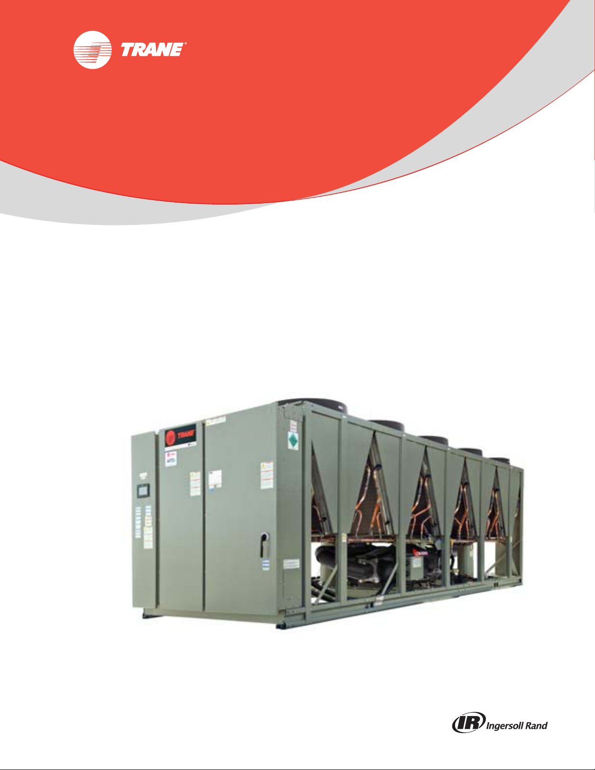
Flow Rates Out of Range
Many process cooling jobs require flow rates that cannot be met with the minimum and maximum
published values within the RTAE evaporator. A simple piping change can alleviate this problem.
For example: a plastic injection molding process requires 80 gpm (5.0 l/s) of 50°F (10°C) water and
returns that water at 60°F (15.6°C). The selected chiller can operate at these temperatures, but has
a minimum flow rate of 106 gpm (6.6 l/s). The system layout in Figure 1 can satisfy the process.
Figure 1. Flow rate out of range systems solution
Flow Proving
Trane provides a factory-installed water flow switch monitored by UC800 which protects the chiller
from operating in loss of flow conditions.
Water Temperature
Leaving Water Temperature Limits
Trane RTAE chillers have three distinct leaving water categories:
• Standard, with a leaving solution range of 40 to 68°F (4.4 to 20°C)
• Low temperature process cooling, with leaving solution less than 40°F (4.4°C)
• Ice-making, with a leaving solution range of 20 to 68°F (-6.7 to 20°C)
Since leaving solution temperatures below 40°F (4.4°C) result in suction temperature at or below
the freezing point of water, a glycol solution is required for all low temperature and ice-making
machines. Ice making control includes dual setpoints and safeties for ice making and standard
cooling capabilities. Consult your local Trane account manager for applications or selections
involving low temperature or ice making machines.
The maximum water temperature that can be circulated through the RTAE evaporator when the
unit is not operating is 125°F (52°C). Evaporator damage may result above this temperature.
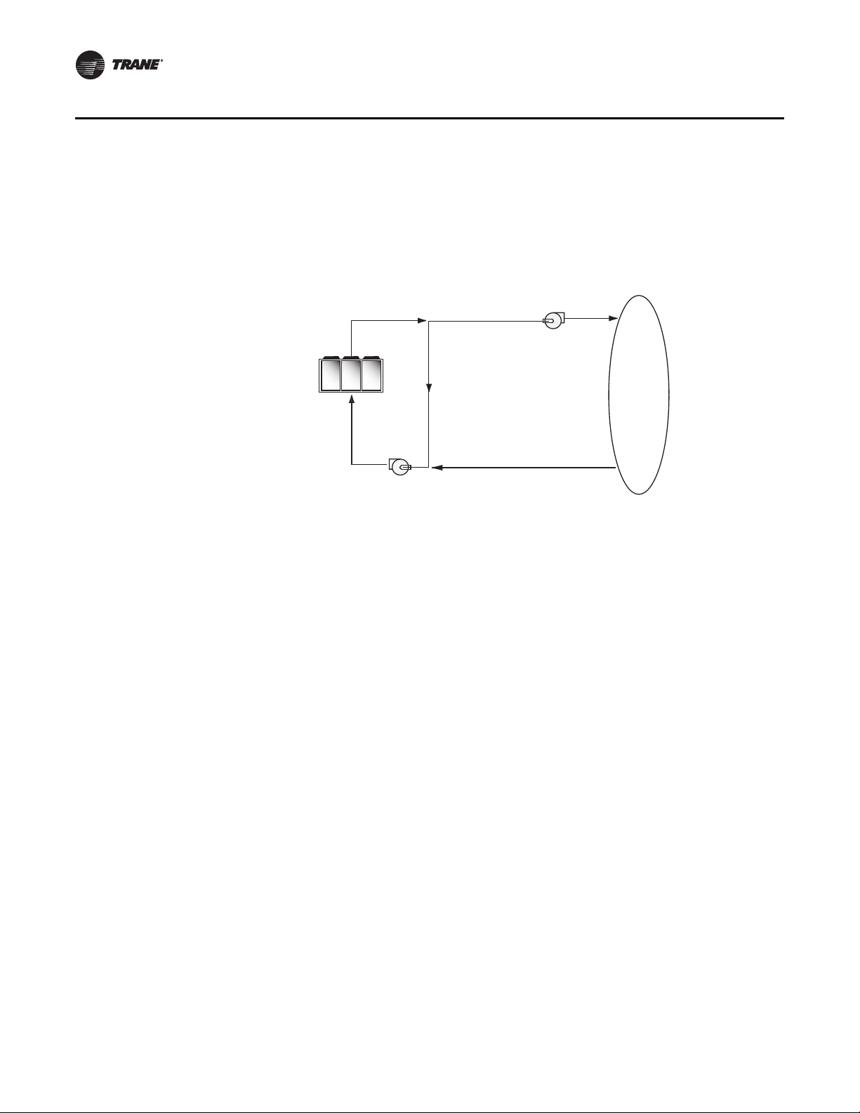
Leaving Water Temperature Out of Range
Many process cooling jobs require temperature ranges that are outside the allowable minimum
and maximum operating values for the chiller. Figure 2 below shows a simple example of a mixed
water piping arrangement change that can permit reliable chiller operation while meeting such
cooling conditions. For example, a laboratory load requires 238 gpm (15 l/s) of water entering the
process at 86°F (30°C) and returning at 95°F (35°C). The chiller’s maximum leaving chilled water
temperature of 68°F (20°C) prevents direct supply to the load. In the example shown, both the chiller
and process flow rates are equal, however, this is not necessary. For example, if the chiller had a
higher flow rate, there would simply be more water bypassing and mixing with warm water
returning to the chiller.
8 RLC-PRC042D-EN
Application Considerations
95°F (35°C)
238 gpm (15 l/s)
LOAD
PUMP
PUMP
80°F
(30°C)
238 gpm
(15 l/s)
59°F
(15°C)
60 gpm
(3.8 l/s)
95°F
(35°C)
178 gpm
(11.2 l/s)
59°F
(15°C)
178 gpm
(11.2 l/s)
68°F (20°C)
238 gpm (15 l/s)
59°F(15°C)
238 gpm (15 l/s)
95°F
(35°C)
60 gpm
(3.8 l/s)
Figure 2. Temperature out of range system solution
Variable Flow in the Evaporator
An attractive chilled water system option may be a variable primary flow (VPF) system. VPF
systems present building owners with several cost saving benefits that are directly related to the
pumps. The most obvious cost savings result from eliminating the secondary distribution pump,
which in turn avoids the expense incurred with the associated piping connections (material, labor),
electrical service, and variable frequency drive. Building owners often cite pump related energy
savings as the reason that prompted them to install a VPF system.
The evaporator on the Stealth can withstand up to 50 percent water flow reduction as long as this
flow is equal to or above the minimum flow rate requirements. The microprocessor and capacity
control algorithms are designed to handle a maximum of 10% change in water flow rate per minute
in order to maintain ± 0.5°F (0.28°C) leaving evaporator temperature control. For applications in
which system energy savings is most important and tight temperature control is classified as +/2°F (1.1°C), up to 30 percent changes in flow per minute are possible.
With the help of a software analysis tool such as System Analyzer™, DOE-2 or TRACE™, you can
determine whether the anticipated energy savings justify the use of variable primary flow in a
particular application. It may also be easier to apply variable primary flow in an existing chilled
water plant. Unlike the "decoupled" system design, the bypass can be positioned at various points
in the chilled water loop and an additional pump is unnecessary.
Series Chiller Arrangements
Another energy saving strategy is to design the system around chillers arranged in series. The
actual savings possible with such strategies depends on the application dynamics and should be
researched by consulting your Trane Systems Solutions Representative and applying an analysis
tool from the Trace software family. It is possible to operate a pair of chillers more efficiently in a
series chiller arrangement than in a parallel arrangement. It is also possible to achieve higher
entering to leaving chiller differentials, which may, in turn, provide the opportunity for lower chilled
water design temperature, lower design flow, and resulting installation and operational cost
savings. The Trane screw compressor also has excellent capabilities for “lift,” which affords an
opportunity for “lift,” which affords an opportunity for savings on the evaporator water loop.
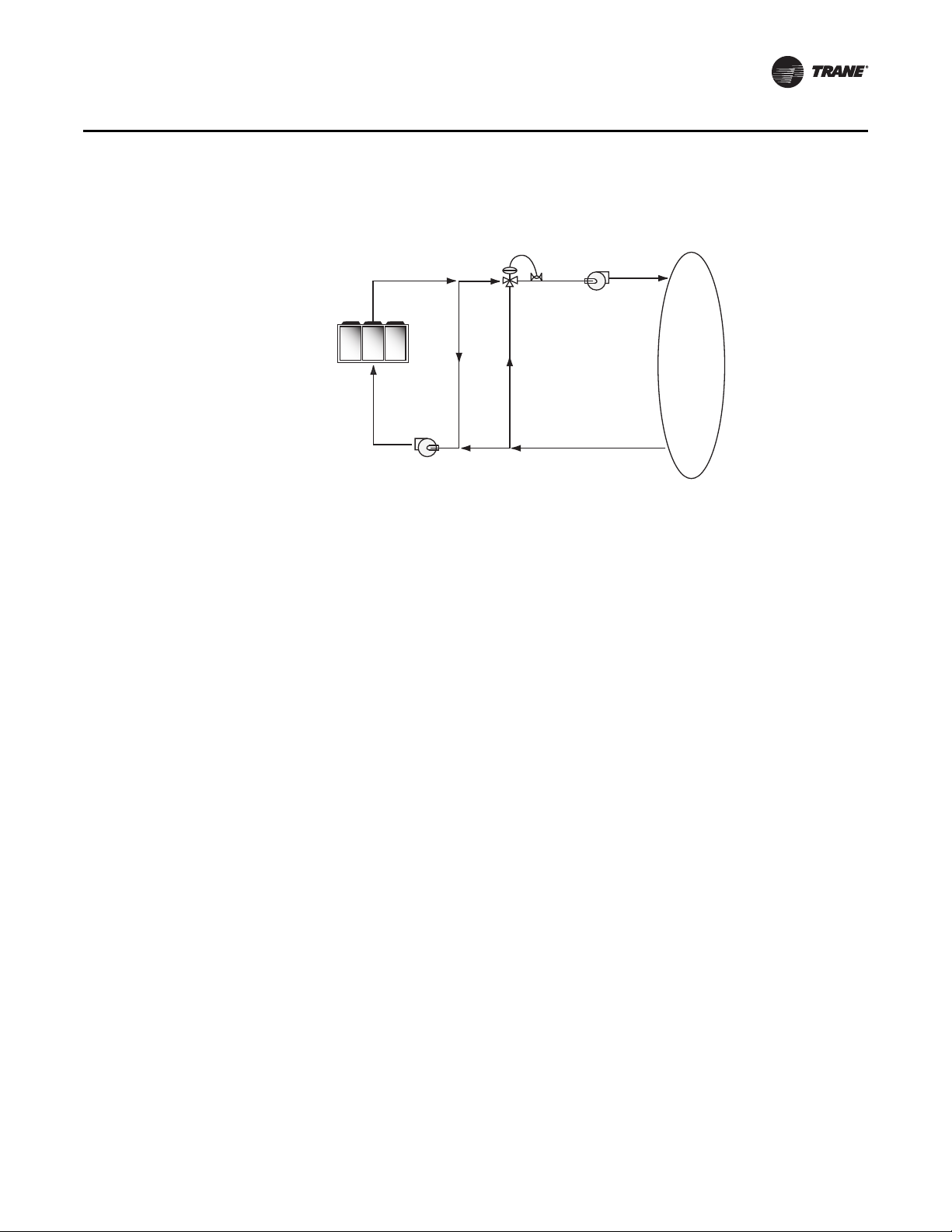
Series chiller arrangements can be controlled in several ways. Figure 3, p. 10 shows a strategy
where each chiller is trying to achieve the system design set point. If the cooling load is less than
50 percent of the systems capabilities, either chiller can fulfill the demand. As system loads
RLC-PRC042D-EN 9
increase, the Chiller 2 becomes preferentially loaded as it attempts to meet the leaving chilled water
Application Considerations
Chiller 2
Setpoint = 42°F (5.6°C)
Chiller 1
Setpoint = 42°F (5.6°C)
Variable
depending
on load
Blending
Valve
58°F
(14.4°C)
42°F (5.6°C)
setpoint. Chiller 1 will finish cooling the leaving water from Chiller 2 down to the system design
setpoint.
Staggering the chiller set points is another control technique that works well for preferentially
loading Chiller 1. If the cooling load is less than 50 percent of the system capacity, Chiller 1 would
be able to satisfy the entire call for cooling. As system loads increase, Chiller 2 is started to meet
any portion of the load that Chiller 1 can not meet.
Figure 3. Typical series chiller arrangement
Typical Water Piping
All building water piping must be flushed prior to making final connections to the chiller. To reduce
heat loss and prevent condensation, insulation should be applied. Expansion tanks are also usually
required so that chilled water volume changes can be accommodated.
Avoidance of Short Water Loops
Adequate chilled water system water volume is an important system design parameter because it
provides for stable chilled water temperature control and helps limit unacceptable short cycling of
chiller compressors.
10 RLC-PRC042D-EN
The chiller’s temperature control sensor is located in the waterbox. This location allows the
building to act as a buffer to slow the rate of change of the system water temperature. If there is
not a sufficient volume of water in the system to provide an adequate buffer, temperature control
can suffer, resulting in erratic system operation and excessive compressor cycling.
Typically, a two-minute water loop circulation time is sufficient to prevent short water loop issues.
Therefore, as a guideline, ensure the volume of water in the chilled water loop equals or exceeds
two times the evaporator flow rate. For systems with a rapidly changing load profile the amount
of volume should be increased.
If the installed system volume does not meet the above recommendations, the following items
should be given careful consideration to increase the volume of water in the system and, therefore,
reduce the rate of change of the return water temperature.
• A volume buffer tank located in the return water piping.

• Larger system supply and return header piping (which also reduces system pressure drop and
pump energy use).
Minimum water volume for a process application
If a chiller is attached to an on/off load such as a process load, it may be difficult for the controller
to respond quickly enough to the very rapid change in return solution temperature if the system
has only the minimum water volume recommended. Such systems may cause chiller low
temperature safety trips or in the extreme case evaporator freezing. In this case, it may be
necessary to add or increase the size of the mixing tank in the return line.
Multiple Unit Operation
Whenever two or more units are used on one chilled water loop, Trane recommends that their
operation be coordinated with a higher level system controller for optimum system efficiency and
reliability. The Trane Tracer system has advanced chilled plant control capabilities designed to
provide such operation.
Ice Storage Operation
An ice storage system uses the chiller to make ice at night when utilities generate electricity more
efficiently with lower demand and energy charges. The stored ice reduces or even replaces
mechanical cooling during the day when utility rates are at their highest. This reduced need for
cooling results in significant utility cost savings and source energy savings.
Another advantage of an ice storage system is its ability to eliminate chiller over sizing. A
“rightsized” chiller plant with ice storage operates more efficiently with smaller support equipment
while lowering the connected load and reducing operating costs. Best of all this system still
provides a capacity safety factor and redundancy by building it into the ice storage capacity for
practically no cost compared to over sized systems.
The Trane air-cooled chiller is uniquely suited to low temperature applications like ice storage
because of the ambient relief experienced at night. Chiller ice making efficiencies are typically
similar to or even better than standard cooling daytime efficiencies as a result of night-time drybulb ambient relief.
Standard smart control strategies for ice storage systems are another advantage of the RTAE
chiller. The dual mode control functionality is integrated right into the chiller. Trane Tracer building
management systems can measure demand and receive pricing signals from the utility and decide
when to use the stored cooling and when to use the chiller.
Application Considerations
Unit Placement
Setting The Unit
A base or foundation is not required if the selected unit location is level and strong enough to
support the unit’s operating weight. (See “Weights,” p. 38.)
For a detailed discussion of base and foundation construction, see the sound engineering bulletin
or the unit IOM. Manuals are available through online product portal pages or from your local
office.
HVAC equipment must be located to minimize sound and vibration transmission to the occupied
spaces of the building structure it serves. If the equipment must be located in close proximity to
a building, it should be placed next to an unoccupied space such as a storage room, mechanical
room, etc. It is not recommended to locate the equipment near occupied, sound sensitive areas of
the building or near windows. Locating the equipment away from structures will also prevent
sound reflection, which can increase sound levels at property lines or other sensitive points.
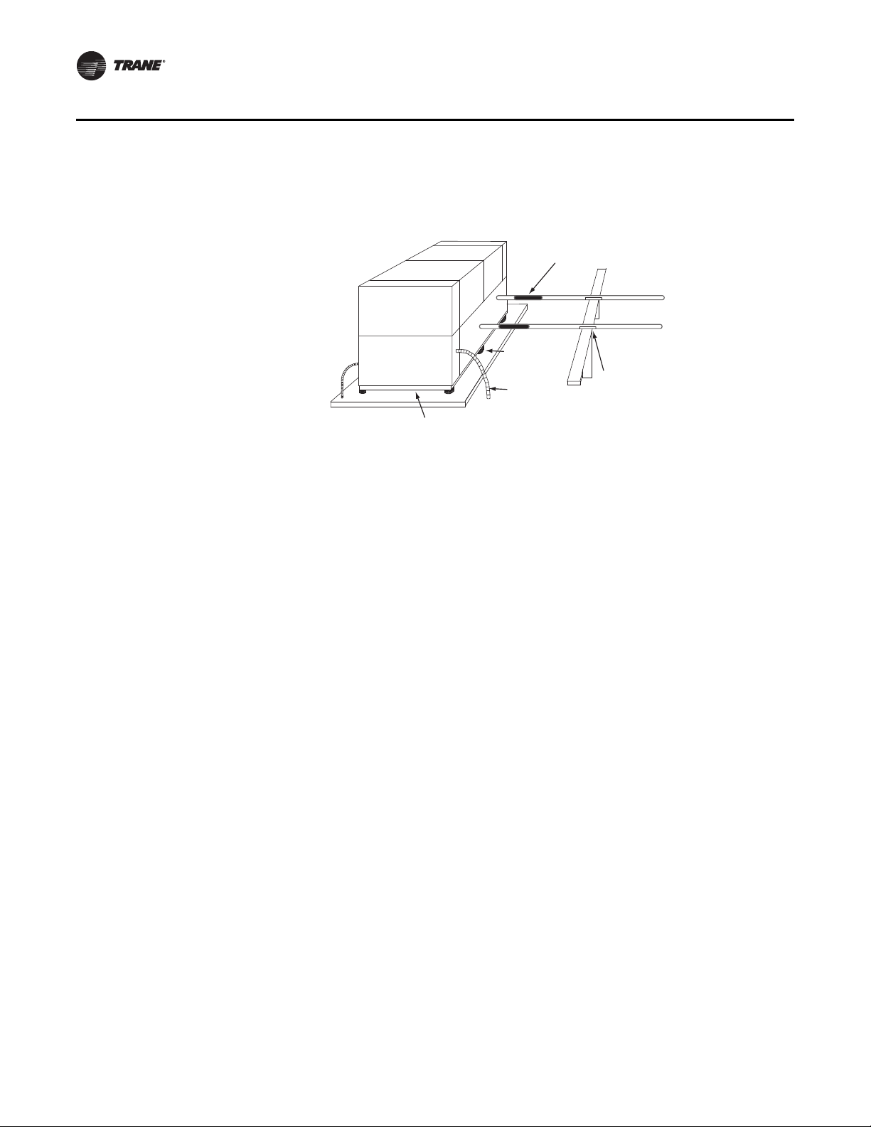
Isolation and Sound Emission
Structurally transmitted sound can be reduced by elastomeric vibration eliminators. Elastomeric
isolators are generally effective in reducing vibratory noise generated by compressors, and
RLC-PRC042D-EN 11
Application Considerations
Piping isolation
Isolators
Chilled water piping
should be supported
Isolators
Flexible
electrical
conduit
Concrete Base
therefore, are recommended for sound sensitive installations. An acoustical engineer should
always be consulted on critical applications.
Figure 4. Installation example
For maximum isolation effect, water lines and electrical conduit should also be isolated. Wall
sleeves and rubber isolated piping hanger s can be used to reduce sound transmitted through water
piping. To reduce the sound transmitted through electrical conduit, use flexible electrical conduit.
Local codes on sound emissions should always be considered. Since the environment in which a
sound source is located affects sound pressure, unit placement must be carefully evaluated. Sound
power levels for chillers are available on request.
Unit Location
Servicing
Adequate clearance for evaporator, condenser and compressor servicing should be provided.
Recommended minimum space envelopes for servicing are located in the dimensional data
section and can serve as a guideline for providing adequate clearance. The minimum space
envelopes also allow for control panel door swing and routine maintenance requirements. Local
code requirements may take precedence.
General
Unobstructed flow of condenser air is essential to maintain chiller capacity and operating
efficiency. When determining unit placement, careful consideration must be given to assure a
sufficient flow of air across the condenser heat transfer surface. Two detrimental conditions are
possible and must be avoided: warm air recirculation and coil starvation. Air recirculation occurs
when discharge air from the condenser fans is recycled back to the condenser coil inlet. Coil
starvation occurs when free airflow to the condenser is restricted.
Condenser coils and fan discharge must be kept free of snow or other obstructions to permit
adequate airflow for satisfactory unit operation. Debris, trash, supplies, etc., should not be allowed
to accumulate in the vicinity of the air-cooled chiller. Supply air movement may draw debris into
the condenser coil, blocking spaces between coil fins and causing coil starvation.
Both warm air recirculation and coil starvation cause reductions in unit efficiency and capacity due
to higher head pressures. The air-cooled RTAE chiller offers an advantage over competitive
equipment in these situations. Operation is minimally affected in many restricted air flow situations
due to its advanced Adaptive Control™ microprocessor which has the ability to understand the
operating environment of the chiller and adapt to it by first optimizing its performance and then
staying on line through abnormal conditions. For example, high ambient temperatures combined
with a restricted air flow situation will generally not cause the air-cooled model RTAE chiller to shut
down. Other chillers would typically shut down on a high pressure nuisance cut-out in these
conditions.
12 RLC-PRC042D-EN

Application Considerations
Cross winds, those perpendicular to the condenser, tend to aid efficient operation in warmer
ambient conditions. However, they tend to be detrimental to operation in lower ambients due to
the accompanying loss of adequate head pressure. Special consideration should be given to low
ambient units. As a result, it is advisable to protect air-cooled chillers from continuous direct winds
exceeding 10 mph (4.5 m/s) in low ambient conditions.
The recommended lateral clearances are depicted in the Close-Spacing and Restricted Airflow
Engineering Bulletin RLC-PRB037*-EN available on product portal pages or from your local office.
Provide Sufficient Unit-to-Unit Clearance
Units should be separated from each other by sufficient distance to prevent warm air recirculation
or coil starvation. Doubling the recommended single unit air-cooled chiller clearances will
generally prove to be adequate. See Close-Spacing and Restricted Airflow Engineering Bulletin
RLC-PRB037*-EN for more information.
Walled Enclosure Installations
When the unit is placed in an enclosure or small depression, the top of the surrounding walls
should be no higher than the top of the fans. The chiller should be completely open above the fan
deck. There should be no roof or structure covering the top of the chiller. Ducting individual fans
is not recommended. See Close-Spacing and Restricted Airflow Engineering Bulletin RLCPRB037*-EN for more information.
RLC-PRC042D-EN 13

Model Number Description
Digits 1,2 — Unit Model
RT = Rotary Chiller
Digits 3— Unit Type
A= Air-cooled
Digits 4 — Development
Sequence
E = Development Sequence
Digits 5-7 — Nominal Capacity
149 = 150 Nominal Tons Single Circuit
164 = 165 Nominal Tons Single Circuit
150 = 150 Nominal Tons
165 = 165 Nominal Tons
180 = 180 Nominal Tons
200 = 200 Nominal Tons
225 = 225 Nominal Tons
250 = 250 Nominal Tons
275 = 275 Nominal Tons
300 = 300 Nominal Tons
Digit 8— Unit Voltage
A = 200/60/3
B = 230/60/3
C = 380/50/3
D = 380/60/3
E = 400/50/3
F = 460/60/3
G = 575/60/3
H = 400/60/3
Digit 9 — Manufacturing
Location
U = Trane Commercial Systems,
Pueblo, CO USA
Digits 10, 11— Design Sequence
XX = Factory assigned
Digit 12 — Unit Sound Package
1 = InvisiSound™ Standard Unit
2 = InvisiSound Superior
(Line Wraps, Reduced Fan Speed)
3 = InvisiSound Ultimate
(Compressor Sound Attenuation,
Line Wraps, Reduced Fan Speed)
Digit 13 — Agency Listing
0 = No Agency Listing
A = UL/CUL Listing
C = CE European Safety Standard
Digit 14 — Pressure Vessel Code
A = ASME Pressure Vessel Code
D = Australia Pressure Vessel Code
C = CRN or Canada Equivalent
Pressure Vessel Code
L = Chinese Pressure Vessel Code
P = PED European Pressure Vessel
Code
Digit 15 — Factory Charge
1 = Refrigerant Charge HFC-134a
2= Nitrogen Charge
Digit 16 — Evaporator
Application
F = Standard Cooling
(40 to 68°F/5.5 to 20°C)
G= Low Temp Process
(<40°F Leaving Temp)
C = Ice-making (20 to 68°F/-7 to 20°C)
w/ Hardwired Interface
Digit 17 — Evaporator
Configuration
N = 2 Pass Evaporator
P = 3 Pass Evaporator
Digit 18 — Evaporator Fluid Type
1= Water
2 = Calcium Chloride
3 = Ethylene Glycol
4 = Propylene Glycol
5= Methanol
Digit 19 — Water Connection
X = Grooved Pipe
F = Grooved Pipe + Flange
Digit 20 — Flow Switch
1 = Factory Installed - Other Fluid
(15 cm/s)
2 = Factory Installed - Water 2
(35 cm/s)
3 = Factory Installed - Water 3
(45 cm/s)
Digit 21 — Insulation
A = Factory Insulation - All Cold Parts
0.75”
B = Evaporator-Only Insulation -
High Humidity/Low Evap Temp
1.25”
Digit 22 — Unit Application
1 = Standard Ambient
(32 to 105°F/0 to 40.6°C)
2= Low Ambient
(0 to 105°F/-17.7 to 40.6°C)
3 = Extreme Low Ambient
(-20 to 105°F/-28.9 to 40.6°C)
4 = High Ambient
(32 to 125°F/0 to 52°C)
5= Wide Ambient
(0 to 125°F/-17.7 to 52°C)
Digit 23 — Condenser Fin
Options
A = Aluminum Fins with Slits
D = CompleteCoat™ Epoxy Coated
Fins
Digits 24, 25 — Not Used
Digit 26 — Power Line
Connection Type
A = Terminal Block
C = Circuit Breaker
D = Circuit Breaker w/ High Fault
Rated Control Panel
Digit 27 — Short Circuit Current
Rating
A = Default A Short Circuit Rating
B = High A Short Circuit Rating
Digit 28 — Transformer
0= No Transformer
1 = Factory Installed Transformer
Digit 29 — Line Voltage
Harmonic Mitigation
X = Line Reactors (~30% TDD)
1 = Filter circuit (IEEE519 Compliant)
Digit 30 — Electrical Accessories
0 = No Convenience Outlet
C = 15A 115V convenience Outlet
(Type B)
Digit 31 — Remote
Communication Options
0= No Remote Digital
1= LonTalk
2 = BACnet
3 = ModBus™ Interface
Communication
®
(Tracer™ Compatible)
(Tracer compatible)
Interface LCI-C
®
MS/TP Interface
Digit 32 — Hard Wire
Communication
X= None
A = Hard Wired Bundle - All
B = Remote Leaving Water Temp
C = Remote Leaving temp and
D = Programmable Relay
E = Programmable Relay and
F= Percent Capacity
G = Percent Capacity and Leaving
H = Percent Capacity and
Setpoint
Demand Limit Setpoints
Leaving Water and Demand Limit
Setpoint
Water and Demand Limit Setpoint
Programmable Relay
Digit 33 — Not Used
14 RLC-PRC042D-EN

Digit 34 — Structural Options
A = Standard Unit Structure
B = Seismic to International Building
Code (IBC)
C = California Office of Statewide
Health Planning and
Development (OSHPD)
Certification
D = Wind Load for Florida Hurricane
175 MPH
E = Seismic (IBC) and Wind Load
F = OSHPD and Wind Load
Digit 35 — Appearance Options
0 = No Appearance Options
A = Architectural Louvered Panels
Digit 36 — Unit Isolation
0 = No Isolation
1 = Elastomeric Isolators
3 = Seismic Rated Isopads
Digit 37 — Not Used
0= Not Used
Digit 38 — Not Used
0= Not Used
Digit 39 — Special
0= None
S= Special
Model Number Description
RLC-PRC042D-EN 15
General Data
Table 1. General data table
Unit Size (tons) 150 165 180 200 225 250 275 300 150SC 165SC
Compressor Model CHHSR CHHSR CHHSR CHHSR CHHSS CHHSS CHHSS CHHSS CHHSS CHHSS
Quantity#2222222211
Evaporator
Water Storage (gal) 17.5 18.7 21.9 23.9 26.6 28.7 33.0 36.0 17.3 17.3
(L) 66.1 70.9 82.8 90.5 100.6 108.8 125.0 136.1 65.6 65.6
2 Pass arrangement
Minimum Flow (gpm) 171 187 202 228 261 288 318 354 169 169
(l/s) 10.8 11.8 12.7 14.4 16.5 18.2 20.1 22.3 10.7 10.7
Maximum Flow (gpm) 626 684 742 835 957 1055 1165 1299 620 620
(l/s) 39.5 43.1 46.8 52.7 60.4 66.5 73.5 81.9 39.1 39.1
3 Pass arrangement
Minimum Flow (gpm) 114 124 135 152 174 192 212 236 113 113
(l/s) 7.2 7.8 8.5 9.6 11.0 12.1 13.4 14.9 7.1 7.1
Maximum Flow (gpm) 417 456 495 557 638 703 777 866 414 414
(l/s) 26.3 28.8 31.2 35.1 40.2 44.3 49.0 54.6 26.1 26.1
Condenser
Qty of Coils 8 10 10 12 12 12 14 16 8 10
Coil Length (in) 78.74 78.74 78.74 78.74 78.74 78.74 78.74 78.74 78.74 78.74
(mm) 2000 2000 2000 2000 2000 2000 2000 2000 2000 2000
Coil Height (in) 50 50 50 50 50 50 50 50 50 50
(mm) 1270 1270 1270 1270 1270 1270 1270 1270 1270 1270
Fins/Ft 192 192 192 192 192 192 192 192 192 192
Rows 3333333333
Condenser Fans
Quantity # 8 10 10 12 12 12 14 16 8 10
Diameter (in) 37.5 37.5 37.5 37.5 37.5 37.5 37.5 37.5 37.5 37.5
(mm) 953 953 953 953 953 953 953 953 953 953
Total Airflow (cfm) 107,392 134,240 134,240 161,088 161,088 161,088 187,936 214,784 107,392 132,240
(m3/hr) 182,460 228,075 228,075 273,690 273,690 273,690 319,305 364,920 182,460 228,075
Tip Speed (ft/min) 8700 8700 8700 8700 8700 8700 8700 8700 8700 8700
(M/S) 44.2 44.2 44.2 44.2 44.2 44.2 44.2 44.2 44.2 44.2
Ambient Temperature Range
Standard Ambient °F (°C) 32 to 105 (0 to 40.6)
Low Ambient °F (°C) 0 to 105 (-17.7 to 40.6)
Extreme Low Ambient °F (°C) -20 to 105 (-28.9 to 40.6)
High Ambient °F (°C) 32 to 125 (0 to 52)
Wide Ambient °F (°C) 0 to 125 (-17.7 to 52)
General Unit
Refrigerant HFC-134a HFC-134a
Refrigerant Ckts # 2 1
Minimum Load%20181715201816153027
Refrigerant Charge/ckt (lbs) 172 181 210 218 265 261 318 325 322 346
(kg) 78 82 95 99 120 118 144 148 146 157
Oil Trane OIL00311
Oil Charge/ckt (gal) 3.0 3.0 3.0 3.0 4.0 4.0 4.0 4.0 4.0 4.0
(L) 11.4 11.4 11.4 11.4 15.1 15.1 15.1 15.1 15.1 15.1
16 RLC-PRC042D-EN
Table 2. Drive cooling
Unit Size (tons)
Standard Length Unit Extended Length Units
150S - 165S 150 165-250 275-300 150S - 165S 150 165-250 275-300
Drive Cooling Fluid Type Trane Heat Transfer Fluid CHM01023
Fluid Volume (gal)
Ckt 1 1.28 1.14 1.23 1.32 1.37 1.30 1.32 1.41
Ckt2 n/a 1.32 1.67 1.81 n/a 1.67 1.81 1.95
Total 1.28 2.46 2.89 3.12 1.37 2.97 3.12 3.36
Fluid Volume (l)
Ckt1 4.86 4.30 4.64 4.98 5.20 4.93 4.98 5.33
Ckt2 n/a 5.01 6.31 6.84 n/a 6.31 6.84 7.38
Total 4.86 9.31 10.95 11.83 5.20 11.23 11.83 12.71
(a) Units are extended length if either of the following are selected:
Transformer (model number digit 28 = 1)
Harmonic Filtration Option (model number digit 29 = 1)
Units without Harmonic Filtration Option or Transformer (digits 28, 29 = 0X) are standard length.
General Data
(a)
RLC-PRC042D-EN 17

Controls
Tracer UC800 Controller
Today’s Stealth™ chiller s offer predictive controls that anticipate and compensate for load changes.
Other control strategies made possible with the Tracer UC800 controls are:
Feedforward Adaptive Control
Feedforward is an open-loop, predictive control strategy designed to anticipate and compensate
for load changes. It uses evaporator entering-water temperature as an indication of load change.
This allows the controller to respond faster and maintain stable leaving-water temperatures.
Soft Loading
The chiller controller uses soft loading except during manual operation. Large adjustments due to
load or setpoint changes are made gradually, preventing the compressor from cycling
unnecessarily. It does this by internally filtering the setpoints to avoid reaching the differential-tostop or the demand limit. Soft loading applies to the leaving chilled-water temperature and demand
limit setpoints.
Adaptive Controls
Adaptive Controls directly sense the control variables that govern the operation of the chiller:
evaporator pressure and condenser pressure. When any one of these variables approaches a limit
condition when damage may occur to the unit or shutdown on a safety, Adaptive Controls takes
corrective action to avoid shutdown and keep the chiller operating. This happens through
combined actions of compressor and/or fan staging. Whenever possible, the chiller is allowed to
continue making chilled water. This keeps cooling capacity available until the problem can be
solved. Overall, the safety controls help keep the building or process running and out of trouble.
Rapid Restart
A Rapid Restart is performed after a momentary power loss occurs during operation. Similarly,
if the chiller shuts down on a non-latching diagnostic and the diagnostic later clears itself, a Rapid
Restart will be initiated.
AdaptiSpeed Control
Compressor speed is used to control capacity of the chiller, optimizing mathematically with the
condenser fan speed to provide the highest level of performance. The increased performance of
the UC800 Controller allows the chiller to operate longer at higher efficiency, and with greater
stability.
Variable-Primary Flow (VPF)
Chilled-water systems that vary the water flow through chiller evaporators have caught the
attention of engineers, contractors, building owners, and operators. Varying the water flow
reduces the energy consumed by pumps, while having limited affect on the chiller energy
consumption. This strategy can be a significant source of energy savings, depending on the
application.
18 RLC-PRC042D-EN
 Loading...