

Page 1
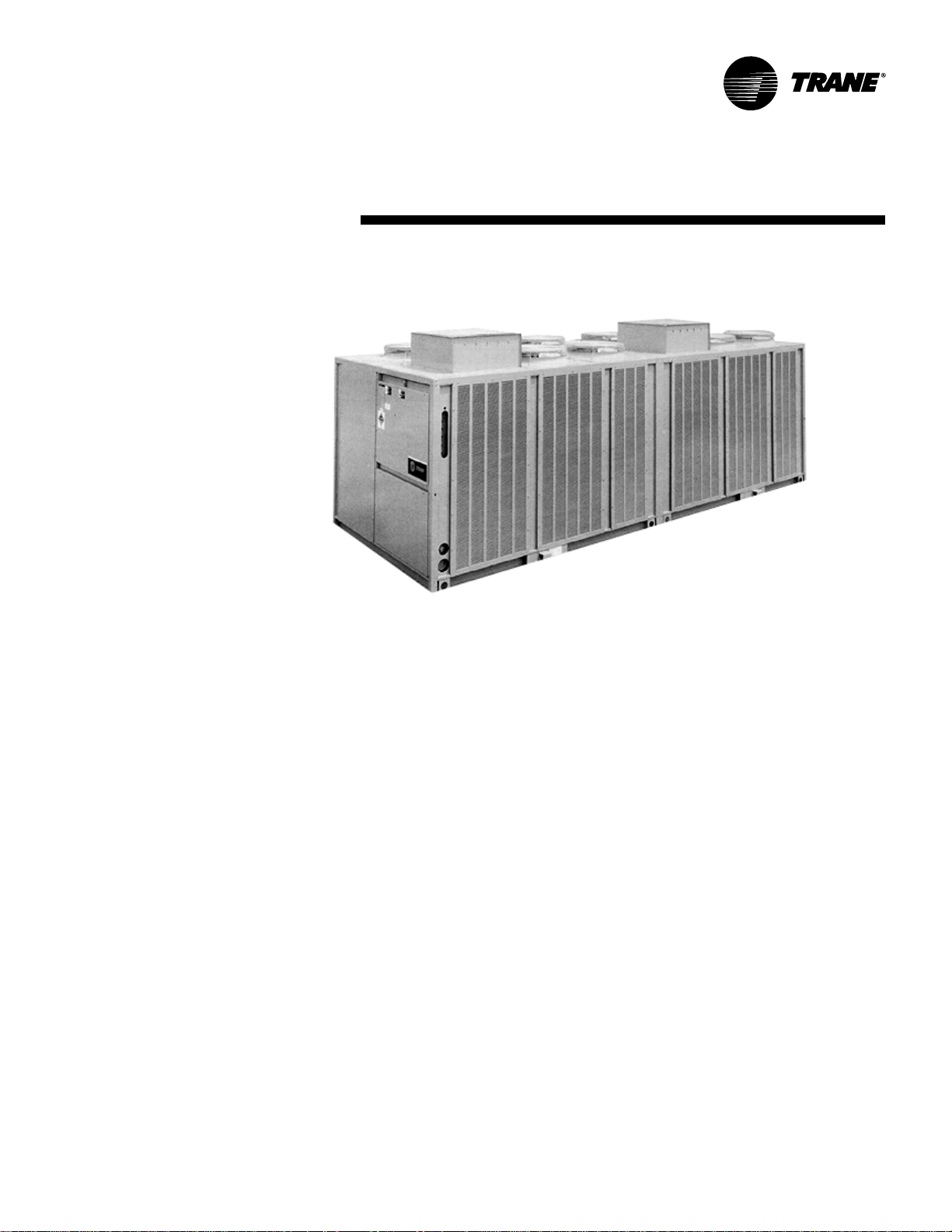
Split System Condensing
Units and Remote Chillers
20 to 120 Tons
50 and 60 Hz
November 2001
SS-PRC005-EN
Page 2
Introduction
©American Standard Inc. 2001
T rane 20 through 120-ton air-cooled
condensing units are the leaders in the
split system marketplace. Designed for
efficiency , reliability and flexibility , the
T rane units have the most advanced
design in the industry.
Twenty through 120-ton units feature
the Trane 3-D™ Scroll compressor, solidstate controls and Trane’s exclusive
Pac ked Stock Plus availability for quick
shipment. These inno vations make an
already proven product even better!
SS-PRC005-EN
Page 3
Contents
Introduction
Featur es and Benefits
Application Considerations
Selection Procedur e
Model Number Description
General Data
P erformance Data
Performance Adjustment Factors
Controls
Electric P o wer
Dimension and Weights
Mechanical Specifications
2
4
6
7
8
10
12
11
25
27
29
46
SS-PRC005-EN
3
Page 4
Trane 3-D Scr oll Compressor
Simple Design with 70% Fewer Par ts
Fewer parts than an equal capacity
reciprocating compressor means
significant reliability and efficiency
benefits. The single orbiting scroll
eliminates the need for pistons,
connecting rods, wrist pins and valves.
Fewer parts lead to increased reliability .
Fewer moving parts, less rotating mass
and less internal friction means greater
efficiency than reciprocating
compressors.
The Trane 3-D Scroll pro vides important
reliability and efficiency benefits. The 3-D
Scroll allows the orbiting scrolls to touch
in all three dimensions, forming a
completely enclosed compression
chamber whic h leads to increased
efficiency . In addition, the orbiting scrolls
only touch with enough force to create a
seal; there is no wear between the scroll
plates. The fixed and orbiting scrolls are
made of high strength cast iron which
results in less thermal distortion, less
leakage, and higher efficiencies. The
most outstanding feature of the 3-D
Scroll compressor is that slugging will
not cause failure. In a reciprocating
compressor, however , the liquid or dir t
can cause serious damage.
Low T orque Variation
The 3-D Scroll compressor has a very
smooth compression cycle; torque
variations are only 30 percent of that
produced by a reciprocating compressor.
This means that the scroll compressor
imposes very little stress on the motor
resulting in greater reliability. Low torque
variation reduces noise and vibration.
Suction Gas Cooled Motor
Compressor motor efficiency and
reliability is further optimized with the
latest scroll design. Cool suction gas
keeps the motor cooler for longer life
and better efficiency.
Proven Design Through T esting and
Research
With over twenty years of development
and testing, Trane 3-D Scroll
compressors have undergone more
than 400,000 hours of laboratory testing
and field operation. This work combined
with over 25 patents makes Trane the
Features and Benefits
worldwide leader in air conditioning
scroll compressor technology .
V oltage P o wer Supply
20 through 120-ton units have four
voltage options in 200, 230, 460 and
575, resulting in improved stock
coverage.
Passive Manif olding
T rane of fers a parallel manifolding
scheme that uses no moving
mechanical parts. This feature assures
continuous oil return, again providing
greater system reliability. And greater
reliability means optimal performance
over the life of the unit.
System Control Options
T rane of fers four system control
options on 20 through 60-ton units and
three system control options on the 80
through 120-ton units, each using
solid- state electronics. These options
allow the unit to be ordered only with
the controls needed. In addition, they
come factory installed, saving field
installation costs.
Coil Frost Pr otection
T rane of fers FROSTA T™ with the V A V
system control option on the 20
through 120-ton units. FROST AT is the
industry’s most reliable method of coil
frost protection and assures that your
system will provide energy efficient
comfort at part load conditions.
Remote Evapor ative Liquid Chiller
(EVP) Control Option
This option allows chilled water to be
generated remotely from the
condensing section.
SS-PRC005-EN4
Page 5
Features and
Benefits
20 Through 60-T on Units
Standard Featur es
• Trane 3-D™ Scroll compressors
• Factory-installed Discharge and Liquid
Line Service V alves
• Passive manifolding for 3-D Scroll
compressors
• Standard ambient operating range
40°F to 115°F
• 14-gauge galvaniz ed steel frame
• Louvered panels for coil protection
• Slate gray air -dry paint finish (exceeds
672 hour salt spray test in accordance
with ASTM B1 17)
Optional Features
• Non-fused disconnect
• Low ambient option
• Hot gas bypass to the evaporator inlet
• Suction service valve
• Pressure gauges
• Return air sensor
• Copper finned condenser coil
• Flow switch
• Unit spring isolators
• Neoprene-in-shear isolators
• UL/CSA approval (not available for 50
Hz)
• Pac ked Stock Plus program
• Extended Compressor W ar ranty
• Special coil coating for corrosion
resistance
• Four systems control options
80 Through 120-T on Units
Standard Featur es
• Trane 3-D Scroll compressors
• Factory-installed discharge and liquid
line service valves
• Standard ambient operating range 40°F
to 115°F
• Independent refrigerant circuits
• 14-gauge g alvanized steel frame
• Louvered panels for coil protection
• Slate gray air -dry paint finish (exceeds
672 hour salt spray test in accordance
with ASTM B1 1 7)
Optional Features
• Low ambient option
• Hot gas bypass to the evaporator inlet
• Suction service valve
• Pressure gauges
• Copper finned condenser coil
• Spring isolators
• Flow switch
• UL/CSA approval
• Pac ked Stoc k Plus A vailability
• Extended Compressor W ar ranty
• Special coil coating for corrosion
resistance
• Three system control options
Pac ked St oc k Plus
T rane 20 through 120-ton air-cooled
condensing units are available through
the most flexible packed stoc k program
in the industry. T rane knows that you
want your units on the job site, on time,
with the options you need.
Pac ked Stock Plus pro vides you with the
controls and options you need — options
like hot gas bypass, isolators and
refrigerant gauges. You no longer have to
settle for a basic unit requiring many field
installed options to meet your job
schedule. Now , you can get a customiz ed
unit from the factory in record time.
The Trane Pa c ked Stoc k Plus program
provides more control over unit selection
and scheduling than ever before. T rane
wants to make it easy for you to do
business with them.
5SS-PRC005-EN
Page 6

Application Considerations
Certain application constraints should be
considered when sizing, selecting and
installing Trane air-cooled condensing
units. Unit reliability is dependent upon
these considerations. Where your
application varies from the guidelines
presented, it should be reviewed with the
local Trane sales engineer .
Unit Sizing
Unit capacities are listed in the
performance data section on pages 11 to
24. Intentionally oversizing a unit to
assure adequate capacity is not
recommended. Erratic system operation
and excessive compressor cycling are
often a direct result of an oversized
condensing unit. In addition, an
oversized unit is usually more expensive
to purchase, install and operate. If
oversizing is desired, consider using two
units.
Unit Placement
A base or foundation is not required if
the selected unit location is level and
strong enough to support the unit’s
operating weight (as listed on page 45).
Isolation and Sound Emission
The most effective form of isolation is to
locate the unit away from any sound
sensitive area. Structurally transmitted
sound can be reduced by using spring or
rubber isolators. The isolators are
effective in reducing the low frequency
sound generated by compressors and,
therefore, are recommended for sound
sensitive installations. An acoustical
engineer should always be consulted on
critical applications.
For maximum isolation effect, the
refrigeration lines and electrical conduit
should also be isolated. Use flexible
electrical conduit. State and local codes
on sound emissions should always be
considered. Since the environment in
which a sound source is located affects
sound pressure, unit placement must be
carefully evaluated.
Servicing
Adequate clearance for compressor
servicing should be provided.
Recommended minimum space
envelopes for servicing are located in the
dimensional data section of this catalog
and can serve as guidelines for providing
adequate clearance. The minimum space
envelopes also allow for control panel
door swing and rountine maintenance
requirements. Local code requirements
may take precedence.
Unit Location
Unobstructed flow of condenser air is
essential for maintaining condensing
unit capacity and operating efficiency .
When determining unit placement,
careful consideration must be given to
assure proper air flow across the
condenser heat transfer surface. Failure
to heed these considerations will result
in warm air recirculatioin and coil air
flow starvation.
Warm air recirculation occurs when
discharge air from the condenser fans is
recycled back at the condenser coil inlet.
Coil starvation occurs when free air flow
to the condenser is restricted.
Both warm air recirculation and coil
starvation cause reductions in unit
efficiency and capacity . In addition, in
more severe cases, nuisance unit
shutdowns will result from exessive
head pressures. Accurate estimates of
the degree of efficiency and capacity
reduction are not possible due to the
unpredictable effect of varying winds.
When hot gas bypass is used, reduced
head pressure increases the minimum
ambient condition for proper operation.
In addition, wind tends to further reduce
head pressure. Therefore, it is advisable
to protect the air -cooled condensing unit
from continuous direct winds exceeding
10 miles per hour.
Debris, trash, supplies, etc., should not
be allowed to accumulate in the vicinity
of the air -cooled condensing unit. Supply
air movement may draw debris between
coil fins and cause coil starvation.
Special consideration should be given to
units operating in low ambient
temperatures. Condenser coils and fan
discharge must be kept free of snow and
other obstructions to permit adequate air
flow for satisfactory unit operation.
Effect of Altitude on Capacity
Condensing unit capacities given in the
performance data tables on pages 11 to
24 are at sea level. At elevations
substantially above sea level, the
decreased air density will decrease
condenser capacity and, therefore, unit
capacity and efficiency. The adjustment
factors in Table PAF -1 can be applied
directly to the catalog performance data
to determine the unit’s adjusted
performance.
Ambient Considerations
Start-up and operation at lower
ambients requires sufficient head
pressure be maintained for proper
expansion valve operation. At higher
ambients, excessive head pressure may
result. Standard operating conditions are
40°F to 115°F. With a low ambient
damper, operation down to 0°F is
possible. Minimum ambient
temperatures are based on still
conditions (winds not exceeding five
mph). Greater wind velocities will result
in increased minimum operating
ambients. Units with hot gas bypass
have a minimum operating ambient
temperature of 10°F. For proper
operation outside these
recommendations, contact the local
T rane sales of fice.
Coil Frost Pr otection
FROST AT™ is standard on condensing
units when the VAV option is ordered.
FROST AT consists of a ship-with
thermostat for field installation on the
suction line. A timer is also factoryinstalled to avoid short cycling. FROSTAT
cycles the compressor off when the
suction line is below 30°F. Refer to
S/S-EB-43 for more detail.
When hot gas valves must be used on 20
to 120-ton units, they can be ordered as
a miscellaneous option. 20 to 30-ton
units require one valve; 40 to 60-ton
units also require one valve except when
no system control option is selected; this
option requires two valves. 80 to 120-ton
units require one valve when Supply Air
VAV control is selected. Two valves are
required on all other 80 to 120-ton
control options.
Refriger ant Piping
Special consideration must always be
given to oil return. Minimum suction gas
velocities must always be maintained for
proper oil return. Utilize appropriate
piping tools for line sizing such as the
CDS Refrigerant Piping Program. Fo r
special applications, call Clarksville
Product Support.
SS-PRC005-EN6
Page 7

Selection Pr ocedure
RAUC/AIR HANDLER
Selection Procedure
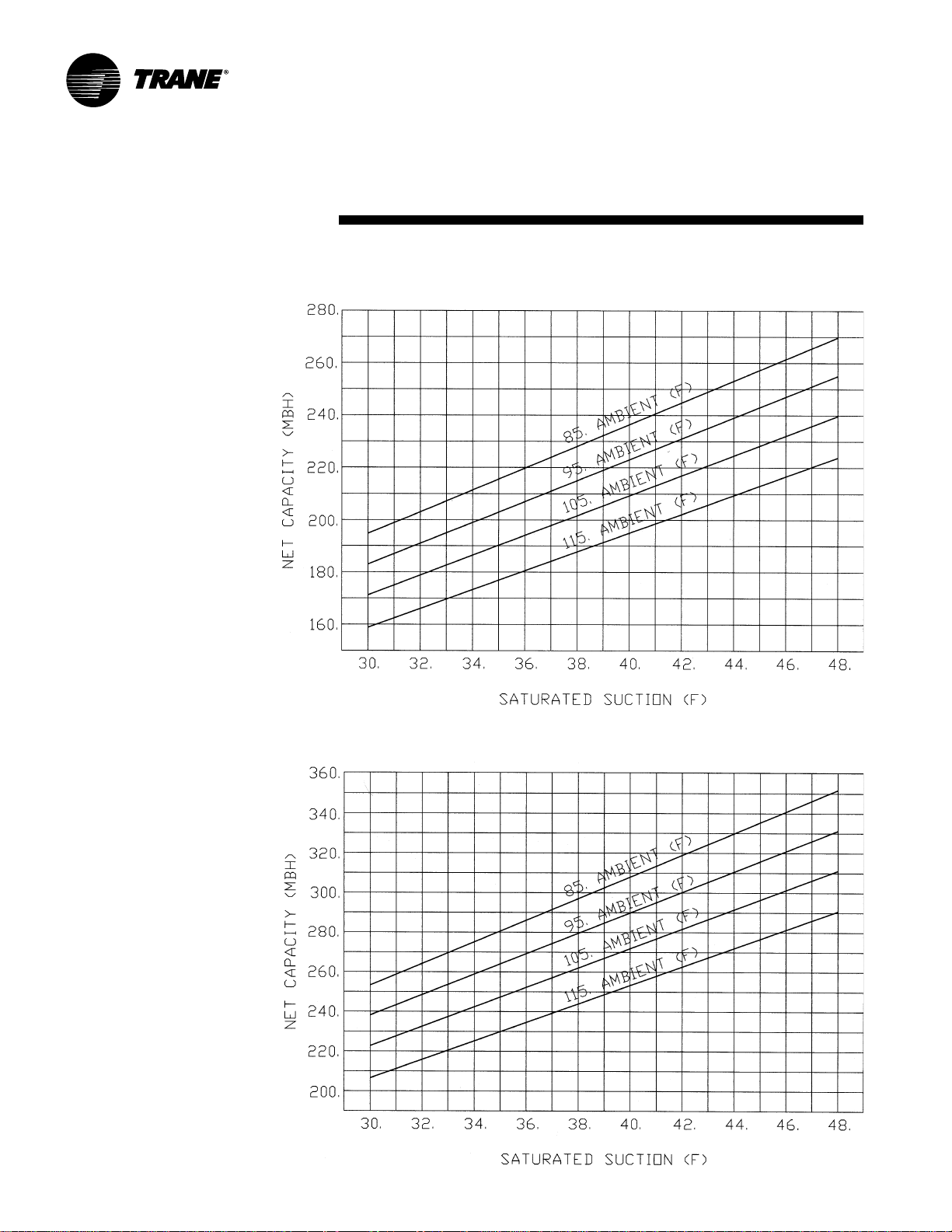
Net capacity curves for the RAUC
condensing units are given on pages 14
through 23. These graphs can be used to
cross plot an evaporator (EVP)
performance curve. The resultant point
of intersection will be the system design
balance point. The design operating
suction temperature and capacity can
then be read directly from the graph.
(Note: It is usually necessary to account
for suction and liquid line losses in the
performance accordingly. The actual
losses are determined by the
interconnecting piping.)
To plot the evaporator performance
curve it is only necessary to obtain gross
evaporator capacities for the given
entering air conditions and cfm at two
different saturated suction temperatures.
The Trane Refrigeration Coil Computer
Selection Program can be used to
conveniently provide the necessary
evaporator capacity values at the
selected suction temperatures.
RAUC/EVP Selection
Procedure
Preselected RAUC/EVP capacities are
provided on pages 12 and 13. To select
for other RAUC/EVP combinations or
conditions, four quantities must be
known. They are:
a.
Entering (EWT) or leaving (L WT) water
temperature.
b.
Net cooling load (T).
c.
Water temperature drop (dt).
d.
Waterflow rate in g allons per minute
(gpm). Knowing any two of the last three
variables (T, dt, and gpm) will determine
the third since
T = (Gpm x dt)/24.
Standard Selection Procedur e
1.
Determine: EWT, T, dt, gpm.
2.
Select an evaporator (EBP) and split
condensing unit (RAUC) to mix -matc h.
3.
Enter Charts PD-18, PD-20, and PD-21 to
find ITD/dt.
4.
From Step 3 calculate the saturated
suction temperature (SST) of the chiller
at the given load using the formula
SST = EWT - [(ITD/dt) x dt].
5.
Enter the appropriate RAUC capacity
char t on pages 1 4-23 with the result on
SST and given load, T. If this point is
below or on the proper condensing unit
performance curve at the same suction
temperature, the RAUC/EVP
combination will meet the desired load.
If above, try a larger chiller and/or
condensing unit. Repeat Steps 2 through
5 until the most economical mix-matc h
has been achieved.
Example
Given:
Ambient Air = 95°F
Supply Water T emperature = 45°F
Waterflow = 230 Gpm
Water Temperature Drop = 10°F
Step 1:
EWT = L WT + dt = 45°F + 1 0°F =
55°F
Gpm = 230 gpm (given)
dt = 10°F (given)
Step 2:
Choose a nominal RAUC and EVP:
RAUC-D1 0 and 1 00-ton EVP
Step 3:
Gpm/nominal tonnage = 230/100 = 2.30
ITD/dt is read from Chart PD-21 as 1.70,
assuming .0005 fouling factor.
Step 4:
SST =
EWT - [(ITD/dt) x dt] =
[55 - (1 .70 x 10)] = 38.0°F = SST
Enter Chart PD-14 at 38.0°F SST and 95
ambient air. The condensing unit will
produce 1182 MBh at 38.0°F SST,
therefore the 100-ton EVP/RAUC-D1 0 is
the proper selection.
Alternative Selection Pr ocedur e
Given: The same information as in the
standard selection procedure plus a
predetermined condensing unit.
Enter the specified RAUC condensing
unit performance curve with the
appropriate cooling load T, to determine
the minimum required suction
temperature.
Enter Chart PD-14 with ITD/dt (EWTsaturated suction temperature/dt) to
determine a gpm/nominal tonnage.
Since the gpm is known, the smallest
nominal size EVP can therefore be
calculated.
Example:
Given:
Ambient Air = 95°F
Condensing Unit - RAUC-C80
Supply Water T emperature - 45°F
dt = 10°F
T = 80.0 Tons
Step 1:
EWT = L WT + dt = 45°F + 1 0°F =
55°F
dt = 10°F
T = 80.0 Tons (960 MBh)
Gpm = 152
Step 2:
Enter Chart PD-13 at 95°F and 80.0 tons
to read the saturated suction
temperature (SST) as 39.7.
Step 3:
Enter Chart PD-21 at an ITD/dt = (EWT SST)/dt = (55 - 39.7)/1 0 = 1.53
Then read the maximum gpm/nominal
tons as 1 .87 (assume .0005 fouling
factor). Therefore since 1.87 = Gpm/
Nominal T on = 152/1.87 = 81.4 T ons. An
80-ton EVP is the optimum selection.
7SS-PRC005-EN
Page 8
Model
Number
20 - 60 Ton
Description
Air-Cooled Condensing Units
20 TO 60-T ON AIR-COOLED CONDENSING UNITS
R A U C C20 E B A 1 0 A 0 0 0 0 0 0 0 0
1 2 3 4 5,6,7 8 9 10 1 1 12 13 14 15 16 17 18 1 9 20 21
DIGIT 1 — UNIT TYPE
R = Condensing Unit
DIGIT 2 — CONDENSER
A = Air Cooled
DIGIT 3 — AIRFLOW
U = Upflow
DIGIT 4 — DEVELOPMENT SEQUENCE
C = Third
DIGITS 5,6,7 — NOMINAL CAP ACIT Y
C20 = 20 Tons
C25 = 25 Tons
C30 = 30 Tons
C40 = 40 Tons
C50 = 50 Tons
C60 = 60 Tons
Remote Chillers
20 TO 60-TON REMOTE CHILLERS
EVP B C20 A 1 *
1,2,3 4 5,6,7 8 9 1 0
DIGIT 1,2,3 — UNIT TYPE
EVP = Evaporative Liquid Chiller
DIGIT 4 — DEVELOPMENT SEQUENCE
(Factory Assigned)
A = First
B = Second
Etc.
Definition of Abbr eviations Used in This Catalog
AL — Aluminum
ASTM — American Society of Testing and Materials
CFM — Cubic Feet Per Minute
Conn. — Connection
CSA — Canadian Standards Association
CU — Copper
DIA. — Diameter
dt — T emperature Dif ference
EER — Energy Efficiency Ratio (Btu/W at t-Hour)
1. The service digit for each model number contains 21 digits; all 21 digits must be referenced.
1
DIGIT 8 — VOL TAGE AND START
CHARACTERISTICS
E = 200/60/3 XL
D = 415/50/3 XL
F = 230/60/3 XL
4 = 460/60/3 XL
5 = 575/60/3 XL
9 = 380/50/3 XL
DIGIT 9 — SY STEM CONTROL
B = No System Control
C = Constant Volume Control
E = Supply Air V A V Control
P = EVP Control
DIGIT 10 — DESIGN SEQUENCE
(Factory Assigned)
A = First
B = Second
Etc.
DIGITS 5,6,7 — NOMINAL CAP ACIT Y
C20 = 20 Tons
C25 = 25 Tons
C30 = 30 Tons
C40 = 40 Tons
C50 = 50 Tons
C60 = 60 Tons
EWT — Entering Water (Solution) T emperature
(F) — Units of Temperature in Degrees F ahrenheit
GPM — Gallons Per Minute
ID — Inside Diameter
(INT) — Internal
IPLV — Integrated Part Load Value
ITD — Initial Temperature Dif ference
k — Thermal Conductivity
KO — Knock Out
DIGIT 1 1 — AMBIENT CONTROL
0 = Standard
1 = 0°F (Low Ambient Dampers)
DIGIT 12 — AGENC Y APPROVAL
0 = None
3 = UL/CSA (not available for 50 Hz)
DIGIT 13-21 — MISCELLANEOUS
A = Unit Disconnect Switch
B = Hot Gas Bypass
D = Suction Service V alve
F = Pressure Gauges
G = Return Air S ensor
H = Copper Fins
T = Flow Switch (EVP Control Option
Only)
1 = Spring Isolators
2 = Rubber Isolators
4 = 5-Y ear Compressor Warranty
9 = Pac ked Stoc k Designator
DIGIT 8 — NUMBER OF CIRCUITS
A = Single (20-30 Ton Units)
D = Dual (40-60 Ton Units)
DIGIT 9 — TUBE MATERIAL
1 = Copper
DIGIT 10 — DESIGN SEQUENCE
(Factory Assigned)
A = First
B = Second
Etc.
SS-PRC005-EN8
Page 9
Model
Number
80 - 120 Ton
Description
Air-Cooled Condensing Units
80 TO 120-TON AIR-COOLED CONDENSING UNIT
R A U C C80 4 B A 0 0 2 B 0 0 0 0 0
1 2 3 4 5,6,7 8 9 10 11 12 13 14 15 16 17 18 19
DIGIT 1 — UNIT TYPE
R = Remote Condensing Unit
DIGIT 2 — CONDENSER
A = Air-Cooled
DIGIT 3 — AIRFL OW
U = Upflow
DIGIT 4 — DEVELOPMENT SEQUENCE
C = Third
DIGITS 5,6,7 — NOMINAL CAP ACIT Y
C80 = 80 Tons
D10 = 1 00 T ons
D12 = 120 T ons
1
DIGIT 8 — VOLTAGE AND S TART
CHARACTERISTICS
E = 200/60/3 XL
D = 415/50/3 XL
F = 230/60/3 XL
4 = 460/60/3 XL
5 = 575/60/3 XL
9 = 380/50/3 XL
DIGIT 9 — SY STEM CONTR OL
B = No System Control
E = Supply Air V A V Control
P = EVP Control
DIGIT 10 — DESIGN SEQUENCE
(Factory Assigned)
A = First
B = Second
Etc.
DIGIT 1 1 — AMBIENT CONTROL
0 = Standard
1 = 0°F (Low Ambient Dampers)
DIGIT 12 — AGENC Y APPROVAL
0 = None
3 = UL/CSA (not available for 50 Hz)
DIGIT 13 — NUMBER OF CIRCUITS
2 = Dual (All 80-120 T on)
DIGIT 14-19 — MISCELLANEOUS
B = Hot Gas Bypass Valve
D = Suction Service V alve
F = Pressure Gauges
H = Copper Fins
1 = Spring Isolators
3 = Flow Switch (EVP Control Option
Only)
Remote Chillers
80 TO 120-TON REMOTE CHILLERS
EVP B C80 D 1 A
1,2,3 4 5,6,7 8 9 10
DIGIT 1,2,3 — UNIT TYPE
EVP = Evaporator Liquid Chiller
DIGIT 4 — DEVELOPMENT SEQUENCE
(Factory Assigned)
A = First
B = Second
Etc.
Definition of Abbreviations Used in This Catalog
KW – Kilowatt (Unit of Power)
lbs. – Pounds (Unit of W eight)
Loc. – Location
LRA –Loc ked Rotor Amps
L WT – Leaving Water (Solution) Temperature
(MBH) – 1 x 10
MTG. – Mounting
NPS – Nominal Pipe Size
1. The service digit for each model number contains 19 digits; all 19 digits must be referenced.
3
Btuh
DIGITS 5,6,7 — NOMINAL CAP A CITY
C80 = 80 Tons
D10 = 1 00Tons
D12 = 120 T ons
DIGIT 8 — NUMBER OF CIRCUITS
D = Dual (80-120 T on Units)
DIGIT 9 — TUBE MATERIAL
1 = Copper
DIGIT 10 — DESIGN SEQUENCE
(Factory Assigned)
A = First
B = Second
Etc.
OD – Outside Diameter
PD – Pressure Drop (Units are Feet of Water)
RLA – Rated Load Amps
SST – Saturated Suction Temperature
UL – Underwriters Laboratories Inc.
VA V – Variable Air Volume
W/ – With
W/O – Without
XL – Across-the-Line-Star t
9SS-PRC005-EN
Page 10
General Data
Table GD-1 — General Data — 20-120 Ton Condensing Units
Nominal Tonnage 20 25 30 40 50 60 80 100 120
Model Number RAUC-C20 RAUC-C25 RAUC-C30 RAUC-C40 RAUC-C50 RAUC-C60 RAUC-C80 RAUC-D10 RAUC-D12
Compressor Data
Type Scroll Scroll Scroll Scroll Scroll Scroll Scroll Scroll Scroll
Manifolded Sets
Circuit #1 10T + 10T 10T + 15T 15T + 15T 10T + 10T 10T + 15T 15T + 15T 10T + 15T + 15T 10T + 10T 15T + 15T
Circuit # 2 N/A N/A N/A 10T + 10T 10T + 15T 15T + 15T 10T + 15T + 15T 10T + 10T 15T +15T
Unit Capacity Steps (%) 100-50 100-40 100-50 100-75-50-25 100-80-60-30 100-75-50-25
No Control & *19-38-50- *20-40-55 *25-50-63
VAV Option 63-81-100 70-85-100 75-88-100
EVP Option *19-38-50 *20-40-55 *25-50-63
Condenser Fan Data
Quantity/Fan Dia./Type 2/26”/Prop. 3/26”/Prop. 3/26”/Prop. 4/26”/Prop. 6/26”/Prop. 6/26”/Prop. 8/26”/Prop. 12/26”/Prop. 12/26”/Prop.
Fan Drive Type Direct Direct Direct Direct Direct Direct Direct Direct Direct
No. of Motors/Hp Each 2/1.0 3/1.0 3/1.0 4/1.0 6/1.0 6/1.0 8/1.0 12/1.0 12/1.0
Nominal Total Cfm 1400 0 18300 20900 28200 35600 4080 0 49600 6680 0 76000
Condenser Coil Data
Number of Coils/Size 1/71x71 1/71x71 1/45x71 2/65x70 2/51x96 2/66x96 4/65x70 4/51x96 4/66x96
(Inches) 1/49x71
Face Area (Sq. Ft.) 35.0 35.0 46.1 63.2 67.1 88.0 126.4 134.2 176.0
Rows/Fins Per Ft. 3/144 3/144 3/144 3/144 3/144 3/144 3/144 3/144 3/144
Condenser Storage 76 76 96 136 142 184 272 284 368
Capacity (Lbs.) (2)
Refrigerant Data (3)
No. Refrigerant Circuits1 11222 222
Refrigerant Type R-22 R-22 R-22 R-22 R-22 R-22 R-22 R-22 R-22
Refrigerant Operating 28 31 40 58 62 80 116 124 160
Charge (Lbs) (1) (4) See note 4 See note 4 See note 4 See note 4 See note 4 See note 4 See note 4 See note 4 See note 4
Minimum Outdoor Air Temperature for Mechanical Cooling
Standard Ambient 40-115 40-115 40-115 40-115 40-115 40-115 40-115 40-115 40-115
Operating Range (F)
Low Ambient Option (F)0 00000 000
Notes:
1. Operating charge is approxmate for condensing unit only, and does not include charge for low side or interconnecting lines.
2. Condenser storage capacity is given at conditions of 95°F outdoor temperature, and 95% full.
3. Refer to Refrigerant Piping under Application Considerations on Page 6.
4. Condensing units are shipped with a nitrogen holding charge only.
Table GD-3 — EER Data — Condensing Unit Only (1)
Nominal Model Capacity Compressor KW Control Condensing Unit
Tonnage Number (MBH) KW Each/Total KW Total KW EER IPLV
20 RAUC-C20 239 19.8 0.9/1.8 0.25 21.9 10.9 15.5
25 RAUC-C25 314 25.3 0.9/2.7 0.25 28.3 11.1 15.2
30 RAUC-C30 376 30.4 0.9/2.7 0.25 33.3 11.3 16.2
40 RAUC-C40 507 40.3 0.9/3.6 0.40 44.3 11.5 16.4
50 RAUC-C50 626 51.2 0.9/5.4 0.40 57.0 11.0 15.7
60 RAUC-C60 748 61.2 0.9/5.4 0.40 67.0 11.2 16.2
80 RAUC-C80 1045 87.9 0.9/7.2 0.50 95.6 10.9 16.1
100 RAUC-D10 1300 110.9 0.9/10.8 0.50 122.1 10.7 15.3
120 RAUC-D12 1560 131.5 0.9/10.8 0.50 142.6 10.9 16.2
Notes:
1. Condensing unit only ratings are in accordance with ARI standard 365. Full load ratings are at 95°F entering air temperature, and refrigerant conditions entering the
condensing unit of 45°F saturated and 60°F actual temperature. Part load ratings are at 80°F entering air temperature and refrigerant conditions entering the condensing
unit of 50°F saturated suction and 65°F actual temperature.
Net Total Unit Condenser Fan
Table GD-2 — Evaporator Chillers — 20-120 Tons
Nominal Tonnage 20 25 30 40 50 60 80 100 120
No. Of Circuits 111222222
Volume Shell (Gal) (1) 11.7 10.7 16.3 13.8 21.0 18.5 43.1 35.0 47.9
Tube Pull (In.) (2) 73 73 74 74 96 96 95 95 95
Refrigerant Operating Charge 8 10 12 16 20 24 26.8 33.4 40.4
Notes:
1. Shell volume is for waterside only.
2. Tube pull given is length of the evaporator.
3. Operating charge is approximate and for the evaporator chiller only.
63-81-100 70-85-100 75-88-100
+15T +15T +15T +15T
+15T +15T +15T +15T
SS-PRC005-EN10
Page 11
P erformance Adjustment Factors
Table P AF -1 — Altitude Corr ection Multiplier f or Capacity
Altitude (Ft.) 2,000 4,000 6,000 8,000 10,000
Condensing Unit Only 0.982 0.960 0.933 0.902 0.866
Condensing Unit / Air Handling Unit Combination 0.983 0.963 0.939 0.911 0.881
Condensing Unit With Evap. 0.986 0.968 0.947 0.921 0.891
Table P AF -2 — Glycol Adjustment Factor for 20-60 Ton Split Condensing Units with the Remote Chiller (EVP) Option
Leaving 0% 10% 20% 30% 40% 50%
Solution Freezing Point = 32°F Freezing Point = 24°F Freezing Point = 1 5°F Freezing Point = 5°F Freezing P oint = -12°F Freezing Point = -33°F
T emp. CAP GPM KW CAP GPM KW CAP GPM KW CAP GPM KW CAP GPM KW CAP GPM KW
10°F — — — — — — .833 .875 .952 .822 .912 .952 .811 .954 .945 .800 1.005 .945
15°F — — — — — — .850 .904 .959 .850 .937 .959 .840 .983 .959 .830 1.029 .953
20°F — — — — — — .882 .928 .971 .873 .962 .965 .864 1.008 .965 .855 1.057 .960
25°F — — — .909 .924 .977 .901 .952 .977 .901 .990 .972 .893 1.031 .972 .876 1.083 .972
30°F — — — .925 .947 .983 .925 .972 .983 .917 1.009 .978 .910 1.053 .978 .895 1.1 01 .978
35°F — — — .945 .963 .989 .938 .989 .989 .931 1.023 .984 .924 1.066 .984 .917 1.115 .978
40°F 1.000 1.000 1.000 .956 .974 .984 .949 1.000 .984 .943 1.034 .984 .937 1.077 .984 .930 1 .124 .979
45°F 1.000 1.000 1.000 .965 .981 .990 .959 1.005 .990 .953 1.039 .985 .947 1.080 .985 .936 1 .1 29 .979
50°F 1.000 1.000 1.000 .962 .982 .990 .957 1.007 .990 .951 1.038 .990 .946 1.079 .985 .935 1 .1 24 .985
Table P AF -3 — Glycol Adjustment Factor for 80-120 Ton Split Condensing Units with the Remote Chiller (EVP) Option
Leaving 0% 10% 20% 30% 40% 50%
Solution Freezing Point = 32°F Freezing Point = 24°F Freezing Point = 15°F Freezing Point = 5°F Freezing P oint = -12°F Freezing Point = -33°F
T emp. CAP GPM KW CAP GPM KW CAP GPM KW CAP GPM KW CAP GPM KW CAP GPM KW
10°F — — — — — — .931 .980 .959 .924 1 .023 .954 .916 1.075 .949 .907 1.131 .944
15°F — — — — — — .943 .991 .967 .936 1 .035 .962 .928 1.085 .957 .919 1.140 .952
20°F — — — .998 1.010 1.000 .955 1.003 .973 .948 1.044 .973 .941 1.094 .969 .933 1 .1 49 .964
25°F — — — .998 1.01 4 1.000 .967 1 .016 .979 .961 1.056 .979 .954 1.106 .975 .946 1.160 .970
30°F — — — .998 1.015 .996 .978 1.030 .984 .973 1.068 .984 .966 1.117 .980 .958 1 .173 .976
35°F — — — .998 1.016 1.000 .987 1.039 .992 .982 1.078 .992 .975 1.124 .989 .968 1 .1 78 .981
40°F 1.000 1.000 1.000 .998 1 .0 1 6 1.000 .994 1.042 .996 .988 1.081 .993 .982 1.127 .989 .974 1.178 .986
45°F 1.000 1.000 1.000 .997 1 .0 1 6 .997 .996 1.045 .997 .991 1.083 .993 .985 1.126 .990 .977 1 .1 78 .986
50°F 1.000 1.000 1.000 .997 1 .0 1 6 1.000 .997 1.046 1.000 .992 1.082 .997 .985 1.124 .990 .978 1.175 .987
Percent of Ethylene Glycol by Weight
Percent of Ethylene Glycol by Weight
11SS-PRC005-EN
Page 12
P erformance Data
20 - 60 Tons
Table PD-1 — Gross Syst em Capacity D ata — 20-60 T on Condensing Unit with Ev aporator Chiller
Condensing Leaving Outside Ambient Temperature Entering Condenser (F)
Unit-Nominal Chilled 85 95 105 115
Tons Model Water T emp. Tons Kw T ons Kw Tons Kw Tons Kw
RAUC C20 40 16.3 17.1 15.5 18.8 14.6 20.9 13.7 23.2
With 42 16.8 17.2 16.0 19.0 15.1 21.1 14.2 23.4
20 T on 45 17 .6 17 .4 16.8 19.2 15.9 21.3 14.9 23.7
20 50 19.0 17.8 18.1 19.6 17.2 21.7 16.2 24.1
25 50 24.6 22.8 23.4 25.2 22.2 27.9 20.9 31 .0
30 30 T on 45 27 .5 26.7 26.2 29.6 24.8 32.9 23.4 36.5
40 50 40.1 35.4 38.2 39.2 36.2 43.4 34.2 48.4
50 50 49.1 46.0 46.7 50.8 44.3 56.4 41.7 62.6
60 50 58.5 54.8 55.7 60.8 52.8 67.4 49.8 75.0
Chiller 48 18.5 17.6 17.6 19.5 16.7 21.6 15.7 24.0
RAUC C20 40 16.8 17.2 16.0 19.0 15.1 21.0 14.1 23.4
With 42 17.4 17.4 16.5 19.2 15.6 21.2 14.6 23.6
25 T on 45 18.2 17 .6 17 .3 19.4 16.4 21 .5 15.4 23.8
Chiller 48 19.1 17.8 18.2 19.6 17 .2 21.8 16.2 24.1
RAUC C25 40 21.0 21.8 20.0 24.1 18.9 26.8 17.8 29.8
With 42 21.7 22.0 20.7 24.4 19.5 27.0 18.4 30.1
25 T on 45 22.8 22.3 21.7 24.7 20.5 27 .4 1 9.3 30.4
Chiller 48 23.9 22.6 22.7 25.0 21.5 27.7 20.3 30.8
RAUC C25 40 21.9 22.1 20.8 24.4 19.7 27.1 18.4 30.1
With 42 22.7 22.3 21.5 24.6 20.3 27.3 19.1 30.3
30 T on 45 23.8 22.6 22.6 24.9 21 .4 27 .6 20.1 30.7
Chiller 48 24.9 22.9 23.7 25.3 22.4 28.0 21.1 31.1
RAUC C30 40 25.4 26.1 24.2 28.9 22.9 32.2 21.5 35.8
With 42 26.3 26.3 25.0 29.2 23.6 32.5 22.3 36.1
Chiller 48 28.9 27.1 27.5 30.0 26.0 33.3 24.5 37.0
RAUC C40 40 34.3 34.2 32.6 37.6 30.8 41.8 28.9 46.4
With 42 35.4 34.4 33.7 38.0 31.8 42.2 29.9 46.8
40 T on 45 37 .1 34.8 35.3 38.4 33.5 42.6 31 .5 47 .4
Chiller 48 38.9 35.2 37.0 39.0 35.1 43.2 33.1 48.0
RAUC C40 40 35.4 34.4 33.6 38.0 31.8 42.0 29.8 46.8
With 42 36.6 34.6 34.8 38.2 32.8 42.4 30.9 47.2
50 T on 45 38.4 35.0 36.5 38.8 33.5 43.0 32.5 47 .8
Chiller 48 40.7 35.6 38.3 39.2 36.2 43.4 34.1 48.4
RAUC C50 40 42.1 44.0 40.0 48.8 37.8 54.0 35.5 60.2
With 42 43.4 44.4 41.3 49.2 39.0 54.6 36.7 60.6
50 T on 45 45.5 45.0 43.3 49.8 40.9 55.2 38.5 61 .4
Chiller 48 47.6 45.6 45.3 50.4 42.9 55.8 40.4 62.0
RAUC C50 40 43.3 44.4 41.1 49.0 38.8 54.4 36.4 60.6
With 42 44.7 44.8 42.4 49.6 40.1 54.8 37.6 61.0
60 T on 45 46.9 45.4 44.5 50.2 42.1 55.6 39.6 61 .8
Chiller 48 49.1 46.0 46.7 50.8 44.2 56.4 41.5 62.4
RAUC C60 40 50.0 52.2 47.6 58.0 45.0 64.6 42.4 71.8
With 42 51.7 52.8 49.2 58.6 46.5 65.2 43.8 72.4
60 T on 45 54.2 53.4 51.6 59.4 48.8 66.0 46.0 73.4
Chiller 48 56.7 54.2 54.0 60.2 51.2 67.0 48.3 74.4
RAUC C60 40 55.1 53.8 52.2 59.6 49.2 66.2 46.1 73.4
With 42 56.9 54.2 54.0 60.2 50.9 66.8 47.8 74.2
80 T on 45 59.8 55.2 56.7 61 .0 53.5 67 .8 50.3 75.2
Chiller 48 62.7 56.0 59.5 62.0 56.2 68.8 52.8 76.2
50 1 9.7 17.9 18.8 19.8 17.8 21 .9 16.7 24.3
50 25.7 23.1 24.4 25.5 23.1 28.2 21.8 31.3
50 29.8 27.3 28.3 30.3 26.9 33.6 25.3 37.3
50 41 .5 35.8 39.5 39.6 37.4 43.8 35.2 48.6
50 50.6 46.4 48.1 51.2 45.6 56.8 42.9 63.0
50 64.7 56.6 61.4 62.6 58.0 69.4 54.6 77.0
SS-PRC005-EN12
Page 13
P erformance
Data
80 - 120 Tons
Table PD-2 — Gross System Capacity D ata — 80-120 T on Condensing Unit with Ev aporator Chiller
Condensing Leaving Outside Ambient Temperature Entering Condenser (F)
Unit-Nominal Chilled 85 95 105 115
T ons Model Water T emp. T ons Kw Tons Kw Tons Kw T ons Kw
RAUC C80 40 65.1 73.9 61.8 81.9 58.3 90.9 54.6 100.9
With 42 67.5 74.7 64.1 82.7 60.5 91.8 56.7 101.8
60 T on 45 71.3 75.8 67 .7 84.0 63.9 93.1 59.8 103.2
Chiller 48 75.1 77.0 71.3 85.2 67.3 94.4 63.1 104.6
RAUC C80 40 70.5 75.6 66.8 83.7 62.9 92.7 58.8 102.8
80 80 T on 45 77 .1 77 .6 73.1 85.8 68.8 95.0 64.4 105.2
100 100 T on 45 96.9 99.7 91.8 1 10.0 86.5 121.6 80.9 134.3
120 50 122.2 120.7 115.9 133.5 109.2 147.8 102.1 163.4
With 42 73.1 76.4 69.3 84.5 65.3 93.6 61.0 103.7
Chiller 48 81.2 78.9 77.0 87.2 72.5 96.4 67.9 106.6
RAUC C80 40 71.4 75.9 67.7 84.0 63.7 93.1 59.5 103.1
With 42 74.1 76.7 70.2 84.9 66.1 94.0 61.8 104.0
100 T on 45 78.2 77 .9 74.1 86.2 69.7 95.4 65.2 105.5
Chiller 48 82.4 79.2 78.0 87.5 73.5 96.8 68.7 107.0
RAUC D10 40 87.1 96.4 82.6 106.6 77.8 118.0 72.7 130.6
With 42 90.3 97.5 85.6 107.7 80.6 11 9.1 75.4 131.8
80 T on 45 95.2 99.1 90.3 109.4 85.0 121.0 79.6 133.7
Chiller 48 100.2 100.8 95.0 111.2 89.6 122.8 83.8 135.6
RAUC D10 40 88.6 96.9 83.9 107.1 79.0 119.7 73.9 131.1
With 42 91.9 98.0 87.1 108.2 73.9 118.5 76.6 132.4
Chiller 48 102.1 101.4 96.7 111.8 91.1 123.5 85.2 136.3
RAUC D10 40 89.4 97.2 84.7 107.4 79.7 118.8 74.5 131.4
With 42 92.7 98.3 87.9 108.5 82.7 120.0 77.3 132.7
120 T on 45 97 .9 100.0 92.7 11 0.4 87 .3 121.9 81 .6 134.6
Chiller 48 103.1 101.8 97.7 112.2 92.0 123.8 86.0 136.6
RAUC D12 40 102.8 114.5 97.4 126.9 91.7 140.8 85.7 156.1
With 42 106.5 115.7 101.0 128.2 95.1 142.1 88.9 157.5
100 T on 45 112.3 11 7 .6 106.4 130.2 100.3 144.2 93.8 159.7
Chiller 48 118.2 119.4 112.0 132.2 105.6 146.3 98.8 161.9
RAUC D12 40 104.1 114.9 98.6 127.3 92.9 141.2 86.8 156.6
With 42 108.0 116.2 102.3 128.7 96.3 142.6 90.0 158.0
120 T on 45 113.9 118.1 107 .9 130.7 101 .6 144.7 95.0 160.3
Chiller 48 120.0 120.0 113.7 132.7 107.1 146.9 100.1 162.5
50 77.7 77.8 73.8 86.1 69.6 95.3 65.3 105.6
50 84.0 79.7 79.6 88.1 75.0 97.4 70.2 107.6
50 85.2 80.1 80.7 88.5 76.0 97.8 71.1 108.0
50 103.7 10 1.9 98.3 1 12.4 92.6 124.1 86.7 136.9
50 105.6 102.6 100.0 11 3.1 94.3 124.7 88.2 137.6
50 106.7 102.9 101 .1 113.5 95.2 125.1 89.1 138.0
50 124.1 121.3 1 1 7.6 134.1 11 0.8 148.4 103.6 164.1
Table PD-3 – Evaporator Chiller Water Pressur e Drop
20 Ton 25 Ton 30 Ton 40 Ton 50 Ton
GPM PD GPM PD GPM PD GPM PD GPM PD
25.0 3.8 30.0 3.7 35.0 2.1 50.0 4.1 60.0 4.0
30.0 5.4 35.0 5.0 40.0 2.7 60.0 5.8 70.0 5.4
35.0 7 .2 40.0 6.4 45.0 3.4 70.0 7.7 80.0 6.9
40.0 9.2 45.0 7.9 50.0 4.1 80.0 9.9 90.0 8.6
45.0 11.5 50.0 9.6 60.0 5.8 90.0 12.3 100.0 10.4
50.0 14.0 60.0 13.5 70.0 7.7 100.0 15.0 120.0 14.7
60.0 19.6 70.0 18.1 80.0 9.9 120.0 21.1 140.0 19.6
70.0 26.1 80.0 23.2 90.0 12.3 140.0 28.1 160.0 25.1
––––100.015.0––––
60 T on 80 T on 100 T on 120 Ton
GPM PD GPM PD GPM PD GPM PD
80.0 5.6 100.0 4.5 120.0 3.2 140.0 3.2
90.0 7.0 120.0 6.5 140.0 4.3 160.0 4.1
100.0 8.5 140.0 8.7 160.0 5.6 180.0 5.2
120.0 12.0 160.0 11.2 180.0 7.0 200.0 6.3
140.0 15.9 180.0 14.1 200.0 8.5 240.0 9.0
160.0 20.5 200.0 17.2 240.0 12.2 280.0 12.0
180.0 25.5 240.0 24.8 280.0 16.3 320.0 15.8
200.0 31.0 – – 320.0 21.0 360.0 19. 7
– – – – 360.0 26.0 400.0 24.0
Notes:
— All capacites are at 10°F Delta water temp. Kw is
total of all compressors, but does not include
condenser fan, water pump and control power.
— 25’ line loss is included.
GPM = Gallons Per Minute
PD = Pressure Drop (Feet of Water)
13SS-PRC005-EN
Page 14
P erformance
20 & 25 Ton
Data — 60 Hz
Chart PD-1 — 20 Ton Condensing Unit Performance — RAUC-C20 (60 HZ)
Condensing Units
Chart PD-2 — 25 Ton Condensing Unit Performance — RAUC-C25 (60 HZ)
SS-PRC005-EN14
Page 15
P erformance
RA UC-C20 & C25
Data — 50 Hz
Chart PD-3 — 20 Ton Condensing Unit P erfor mance — RA UC-C20 (50 HZ)
Condensing Units
Chart PD-4 — 25 Ton Condensing Unit P erfor mance — RA UC-C25 (50 HZ)
15SS-PRC005-EN
Page 16

P erformance
30 & 40 Ton
Data — 60 Hz
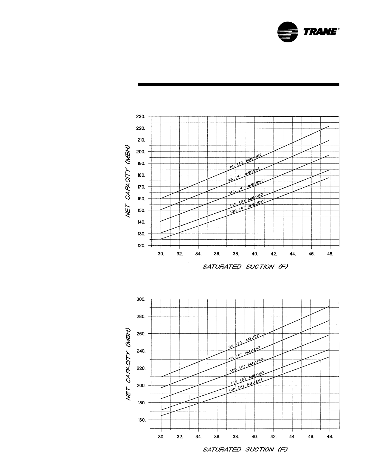
Chart PD-5 — 30 Ton Condensing Unit Performance — RAUC-C30 (60 HZ)
Condensing Units
Chart PD-6— 40 Ton Condensing Unit Performance — RAUC-C40 (60 HZ)
SS-PRC005-EN16
Page 17

P erformance
RA UC-C30 & C40
Data — 50 Hz
Chart PD-7 — 30 Ton Condensing Unit P erfor mance — RA UC-C30 (50 HZ)
Condensing Units
Chart PD-8 — 40 Ton Condensing Unit P erfor mance — RA UC-C40 (50 HZ)
17SS-PRC005-EN
Page 18

P erformance
50 & 60 Ton
Data — 60 Hz
Chart PD-9 — 50 Ton Condensing Unit Performance — RAUC-C50 (60 HZ)
Condensing Units
Chart PD-10— 60 Ton Condensing Unit Performance — RAUC-C60 (60 HZ)
SS-PRC005-EN18
Page 19

P erformance
RA UC-C50 & C60
Data — 50 Hz
Chart PD-1 1 — 50 Ton Condensing Unit Perfor mance — RAUC-C50 (50 HZ)
Condensing Units
Chart PD-12 — 60 Ton Condensing Unit P erformance — RAUC-C60 (50 HZ)
19SS-PRC005-EN
Page 20

P erformance
80 & 1 00 Ton
Data — 60 Hz
Chart PD-13 — 80 Ton Condensing Unit Performance — RAUC-C80 (60 HZ)
Condensing Units
Chart PD-14 — 100 T on Condensing Unit P erfor mance — RA UC-D1 0 (60 HZ)
SS-PRC005-EN20
Page 21

P erformance
RA UC-C80 & D1 0
Data — 50 Hz
Chart PD-15 — 80 Ton Condensing Unit P erfor mance — RA UC-C80 (50 HZ)
Condensing Units
Chart PD-16 — 1 00 Ton Condensing Unit P erf or mance — RAUC-D10 (50 HZ)
21SS-PRC005-EN
Page 22

P erformance
120 Ton
Data — 60 Hz
Chart PD-17 — 120 T on Condensing Unit P erfor mance — RA UC-D12 (60 HZ)
Condensing Units
20-60 Ton Evaporator Chiller Option
Chart PD-18 – EVP Perf ormance Curv e – 20 thr ough 40 T ons
SS-PRC005-EN22
Page 23

P erformance
RA UC-D12
Data — 50 Hz
Chart PD-19 — 120 Ton Condensing Unit P erf or mance — RAUC-D12 (50 HZ)
Condensing Units
23SS-PRC005-EN
Page 24

P erformance
20-60 Ton Evaporator
Data — 60 HZ
Chart PD-20 — EVP Perfor mance Curve — 50 and 60 Tons
Chiller Option
80-120 Ton Evaporator Chiller Option
Chart PD-21 — EVP Perfor mance Curve — 80 thr ough 120 Tons
SS-PRC005-EN24
Page 25

Controls 20-60 Tons
Standard Options
20 through 60-Ton Condensing Units
System Control Options
Select one of the four following control
options to meet your application
requirements.
• No System Control pro vides the
compressors wired to a terminal strip
inside the control panel. The temperature
controller must be field provided and
installed. The 20, 25 and 30-ton have two
capacity steps. The 40, 50 and 60-ton
sizes have four steps available.
• Constant V olume Control includes a
W973 controller with two cool, four heat
steps on the 20, 25 and 30-ton sizes. Four
cool, four heat steps are provided on the
40, 50 and 60-ton sizes. The heating
contacts are wired to terminals in the
condensing unit control panel for easy
interface with a field supplied electric
duct heater or gas duct furnace. An
optional return air sensor is available
with this controller which provides the
zone temperature input to the
thermostat, thus generating the loading
demand signal to the Honeywell W973
constant volume controller .
• Supply Air V A V Control provides a
Honeywell W71 00A control system. This
option is for use with shut-off VAV or
other applications requiring control of
supply air temperature. The control
provides a voltage output for interface
with field supplied components to
provide simultaneous economizer
operation. The discharge air sensor
ships with the unit for field mounting.
The standard VAV unit is provided with
reliable coil frost protection in the form
of Trane’s proven and patented
FROST AT™. FROSTA T is used in place
of hot gas bypass.
• EVP Control consists of an interface
panel in the main unit control box and a
remote mounted control box that is
customer installed. The remote mounted
box contains the Honeywell W7100G
controller. This water c hiller controller
has built in fixed-off timers and chiller
freeze protection. No provision for
periodic pumpout or lead-lag is
provided. Multiple chiller control is not
provided. There are two capacity steps
on 20, 25 and 30-ton sizes. Four capacity
steps are provided on the 40, 50 and 60ton sizes.
Low Ambient Control Option
• Standard — Unit start-up and operation
down to approximately 40°F at
minimum compressor load.
• Low Ambient — Factory-installed head
pressure control damper assembly
permits operation down to 0°F by
maintaining proper head pressure. Ten
minute timer is standard for protection
against nuisance trips.
Miscellaneous Options
20 through 60-Ton Condensing Units
Select the miscellaneous options to meet
your project requirements.
• Non-Fused Unit Disconnect Switch– A
non-fused disconnect switch is mounted
in the control box and provides for
interruption of power for servicing the
unit. Lugs are suitable for copper wires
only. No overcur rent or shor t circuit
protection is provided for the unit by this
switch.
• Hot Gas Bypass V alv e — Hot gas
bypass valves are stocked and shipped
with the unit for field installation. When
suction pressure falls below the valve
adjustable set point, the valve modulates
hot gas to the inlet of the evaporator .
(Note: FROST AT is standard on V A V units
and is recommended in place of hot gas
bypass).
25SS-PRC005-EN
Page 26

Controls 80-120 Ton
Standard Options
80 through 120-Ton Condensing Units
System Control Options
Select one of the three following control
options to meet your application
requirements.
• Supply Air V A V includes a multi-step,
demand oriented, microprocessor -based
Honeywell W7100 discharge air
controller. W7100 control is designed for
shut-off VAV systems. A verage disc harge
air temperature is maintained by
modulating an economizer and if
needed, simultaneously sequencing
stages of mechanical cooling. Field
installation of the factory supplied
discharge air sensor is required.
• No System Control option does not
provide any temperature control
components. The temperature control
components are supplied by others and
specifically designed for the unit’s
application. This option includes all
compressor steps wired to a terminal
strip for easy customer connection of
field provided controls. Fixed-on and
off timers are provided for compressor
protection.
• EVP Control consists of an interface
panel in the main unit control box and
a remote mounted control box that is
customer installed. The remote
mounted box contains the Honeywell
W7100G controller. This water c hiller
controller has built in fixed-off timers
and chiller freeze protection. No
provision for periodic pumpout or leadlag is provided. Multiple chiller control
is not provided. There are six capacity
steps on 80-120 ton models.
Low Ambient Control Option
• Standard — Unit start-up and
operation down to approximately 40°F
at minimum compressor load.
• Low Ambient — Factory or fieldinstalled head pressure control damper
assembly permits operation down to
0°F by maintaining proper head
pressure. Ten minute time is standard
for protection against nuisance trips.
Miscellaneous Options
80 through 120-Ton Condensing Units
Select the options to meet project
requirements.
• Hot Gas Bypass V alv e maintains
minimum refrigerant volume through
compressor for proper motor cooling
while holding suction temperature above
the minimum during low load conditions.
When suction pressure falls below the
valve adjustable set point, the valve
modulates hot gas to the inlet of the
evaporator. Connections include ¼-inc h
SAE flare connection to suction line for
external equalizer line and 115-volt
electrical connection for the integral liquid
line solenoid valve. (Note: FROST AT is
standard on V AV units and is
recommended in place of hot gas bypass.)
• Spring Isolators — Vibration isolators
field-installed under unit to reduce
transmission of vibration to building
structure and adjacent areas.
• Pressure Gauges available for suction and
discharge for eac h refrigerant circuit.
Gauges mount adjacent to compressors.
SS-PRC005-EN26
Page 27

Electrical Data
Table ED-1 — Condensing Units — 60 Hz
Nominal Model V oltage/Start V oltage Circuit Ampacity Protection Device Element Fuse Size Of
T on s Number Characteristics Utilization Range (1), (4) (2), (4) (3), (4) Compressors
20 RAUC-C204 460/60/3XL 414-506 44 60 50 2
25 RAUC-C254 460/60/3XL 414-506 56 80 70 2
30 RAUC-C304 460/60/3XL 414-506 65 90 80 2
40 RAUC-C404 460/60/3XL 414-506 84 100 90 4
50 RAUC-C504 460/60/3XL 414-506 106 125 125 4
60 RAUC-C604 460/60/3XL 414-506 123 125 125 4
80 RAUC-C804 460/60/3XL 414-506 162 175 175 6
100 RAUC-D104 460/60/3XL 414-506 206 225 225 8
120 RAUC-D124 460/60/3XL 414-506 239 250 250 8
Notes:
1. Minimum circuit ampacity (MCA) is 125 percent of the RLA of one compressor motor plus the total RLA of the remaining motors.
2. Maximum Overcurrent Protection Device permitted by NEC 440-22 is 225 percent of the RLA of one compressor motor plus the total RLA of the remaining motors.
3. Recommended dual element fuse size is 150 percent of the RLA of one compressor motor plus the total RLA of the remaining motors.
4. Local codes may take precedence.
RAUC-C20E 200/60/3XL 180-220 101 125 125 2
RAUC-C20F 230/60/3XL 207-253 101 125 125 2
RAUC-C205 575/60/3XL 517-633 35 45 40 2
RAUC-C25E 200/60/3XL 180-220 129 175 150 2
RAUC-C25F 230/60/3XL 207-253 129 175 150 2
RAUC-C255 575/60/3XL 517-633 45 60 60 2
RAUC-C30E 200/60/3XL 180-220 148 200 175 2
RAUC-C30F 230/60/3XL 207-253 148 200 175 2
RAUC-C305 575/60/3XL 517-633 52 70 60 2
RAUC-C40E 200/60/3XL 180-220 192 225 225 4
RAUC-C40F 230/60/3XL 207-253 192 225 225 4
RAUC-C405 575/60/3XL 517-633 67 80 80 4
RAUC-C50E 200/60/3XL 180-220 244 300 300 4
RAUC-C50F 230/60/3XL 207-253 244 300 300 4
RAUC-C505 575/60/3XL 517-633 84 100 90 4
RAUC-C60E 200/60/3XL 180-220 282 300 300 4
RAUC-C60F 230/60/3XL 207-253 282 300 300 4
RAUC-C605 575/60/3XL 517-633 98 110 11 0 4
RAUC-C80E 200/60/3XL 180-220 373 400 400 6
RAUC-C80F 230/60/3XL 207-253 373 400 400 6
RAUC-C805 575/60/3XL 517-633 129 150 150 6
RAUC-D10E 200/60/3XL 180-220 472 500 500 8
RAUC-D10F 230/60/3XL 207-253 472 500 500 8
RAUC-D105 575/60/3XL 517-633 164 175 175 8
RAUC-D12E 200/60/3XL 180-220 548 600 600 8
RAUC-D12F 230/60/3XL 207-253 548 600 600 8
RAUC-D125 575/60/3XL 517-633 190 200 200 8
Allowable Minimum Max. Overcurrent Recommended Dual Number
Unit Characteristics
Table ED-2— Condensing Units — 50 Hz
Unit Characteristics
Nominal Model Voltage/Start Voltage Circuit Ampacity Protection Device Element Fuse Size Of
Tons Number Characteristics Utilization Range (1), (4) (2), (4) (3), (4) Compressors
20 RAUC-C20 380/415/50/3XL 360-440 42 50 50 2
25 RAUC-C25 380/415/50/3XL 360-440 55 80 70 2
30 RAUC-C30 380/415/50/3XL 360-440 64 90 80 2
40 RAUC-C40 380/415/50/3XL 360-440 80 90 90 4
50 RAUC-C50 380/415/50/3XL 360-440 104 125 125 4
60 RAUC-C60 380/415/50/3XL 360-440 122 125 125 4
80 RAUC-C80 380/415/50/3XL 360-440 159 175 175 6
100 RAUC-D10 380/415/50/3XL 360-440 201 225 225 8
120 RAUC-D12 380/415/50/3XL 360-440 237 250 250 8
Notes:
1. Minimum circuit ampacity (MCA) is 125 percent of the RLA of one compressor motor plus the total RLA of the remaining motors.
2. Maximum Overcurrent Protection Device permitted by NEC 440-22 is 225 percent of the RLA of one compressor motor plus the total RLA of the remaining motors.
3. Recommended dual element fuse size is 150 percent of the RLA of one compressor motor plus the total RLA of the remaining motors.
4. Local codes may take precedence.
Allowable Minimum Max. Overcurrent Recommended Dual Number
27SS-PRC005-EN
Page 28

Electrical
Data
Table ED-3 — Compressor Motor and Condenser Fan Data — 60 Hz
Nominal Compressor 1A (1) Compressor 1B Compressor 2A Compressor 2B Condenser Fans
T o ns Model V oltage RLA LRA RLA LRA RLA LRA RLA LRA Qty. FLA
20 RAUC-C20 460 XL 18.1 117 18.1 1 17 — — — — 2 1.8
25 RAUC-C25 460 XL 18.1 117 26.3 178 — — — — 3 1.8
30 RAUC-C30 460 XL 26.3 178 26.3 178 — — — — 3 1.8
40 RAUC-C40 460 XL 18.1 117 18.1 1 17 18.1 117 18.1 117 4 1.8
50 RAUC-C50 460 XL 18.1 117 26.3 178 18.1 117 26.3 178 6 1.8
60 RAUC-C60 460 XL 26.3 178 26.3 178 26.3 178 26.3 178 6 1.8
Nominal Compressor 1A/2A(2) Compressor 1B/2B Compressor 1C/2C Compressor 1D/2D Condenser Fans
T ons Model Voltage RLA LRA RLA LRA RLA LRA RLA LRA Qty. FLA
80 RAUC-C80 460 XL 18.1 117 26.3 178 26.3 178 — — 8 1.8
100 RAUC-D10 460 XL 26.3 178 26.3 178 18.1 1 17 18.1 117 12 1.8
120 RAUC-D12 460 XL 26.3 178 26.3 178 26.3 178 26.3 178 12 1.8
Notes:
1. Value given is per compressor on 20-60 ton units.
2. For 80 through 120-ton units, electrical values shown are for each compressor.
200 XL 41.4 269 41.4 269 — — — — 2 4.1
230 XL 41.4 251 41.4 251 –– –– –– –– 2 4.1
575 XL 14.4 94 14.4 94 — — — — 2 1.4
200 XL 41.4 269 60.5 409 — — — — 3 4.1
230 XL 41.4 251 60.5 376 –– –– –– –– 3 4.1
575 XL 14.4 94 21.0 143 — — — — 3 1.4
200 XL 60.5 409 60.5 409 — — — — 3 4.1
230 XL 60.5 376 60.5 376 –– –– –– –– 3 4.1
575 XL 21.0 143 21.0 143 — — — — 3 1.4
200 XL 41.4 269 41.4 269 41.4 269 41.4 269 4 4.1
230 XL 41.4 251 41.4 251 41.4 251 41.4 251 4 4.1
575 XL 14.4 94 14.4 94 14.4 94 14.4 94 4 1.4
200 XL 41.4 269 60.5 409 41.4 269 60.5 409 6 4.1
230 XL 41.4 251 60.5 376 41.4 251 60.5 376 6 4.1
575 XL 14.4 94 21.0 143 14.4 94 21.0 143 6 1.4
200 XL 60.5 409 60.5 409 60.5 409 60.5 409 6 4.1
230 XL 60.5 376 60.5 376 60.5 376 60.5 376 6 4.1
575 XL 21.0 143 21.0 143 21.0 143 21.0 143 6 1 .4
200 XL 41.4 269 60.5 409 60.5 409 — — 8 4.1
230 XL 41.4 251 60.5 376 60.5 376 –– –– 8 4.1
575 XL 14.4 94 21.0 143 21.0 143 — — 8 1.4
200 XL 60.5 409 60.5 409 41.4 269 41.4 269 12 4.1
230 XL 60.5 376 60.5 376 41.4 251 41.4 251 12 4.1
575 XL 21.0 143 21.0 143 14.4 94 14.4 94 12 1.4
200 XL 60.5 409 60.5 409 60.5 409 60.5 409 12 4.1
230 XL 60.5 376 60.5 376 60.5 376 60.5 376 12 4.1
575 XL 21.0 143 21.0 143 21.0 143 21.0 143 12 1.4
Table ED-4 — Compressor Motor and Condenser Fan Data — 50 Hz
Nominal Compressor 1A (1) Compressor 1B Compressor 2A Compressor 2B Condenser Fans
T o ns Model V oltage RLA LRA RLA LRA RLA LRA RLA LRA Qty. FLA
20 RAUC-C20 380/415 17.2 1 1 0 17.2 11 0 — — — — 2 1.7
25 RAUC-C25 380/415 17.2 1 1 0 26.2 174 — — — — 3 1.7
30 RAUC-C30 380/415 26.2 174 26.2 174 — — — — 3 1.7
40 RAUC-C40 380/415 17.2 1 1 0 17.2 11 0 — — — — 4 1.7
50 RAUC-C50 380/415 17.2 1 1 0 26.2 174 — — — — 6 1.7
60 RAUC-C60 380/415 26.2 174 26.2 174 — — — — 6 1.7
Nominal Compressor 1A/2A(2) Compressor 1B/2B Compressor 1C/2C Compressor 1D/2D Condenser Fans
T ons Model Voltage RLA LRA RLA LRA RLA LRA RLA LRA Qty. FLA
80 RAUC-C80 380/415 17.2 174 26.2 174 26.2 174 — — 8 1.7
100 RAUC-D10 380/415 26.2 174 26.2 174 17.2 11 0 17.2 11 0 12 1.7
120 RAUC-D12 380/415 26.2 174 26.2 174 26.2 174 26.2 174 12 1.7
Notes:
1. Value given is per compressor on 20-60 ton units.
2. For 80 through 120-ton units, electrical values shown are for each compressor.
SS-PRC005-EN28
Page 29

Dimensional
20 Ton
Data
Figure DD-1 — Air -Cooled Condensing Unit — RA UC 20 T on
Condensing Unit
29SS-PRC005-EN
Page 30

Dimensional
25 Ton
Data
Figure DD-2 — Air -Cooled Condensing Unit — RA UC 25 T on
Condensing Unit
SS-PRC005-EN30
Page 31

Dimensional
30 Ton
Data
Figure DD-3 — Air -Cooled Condensing Unit — RA UC 30 T on
Condensing Unit
31SS-PRC005-EN
Page 32

Dimensional
40 Ton
Data
Figure DD-4 — Air -Cooled Condensing Unit — RA UC 40 T on
Condensing Unit
SS-PRC005-EN32
Page 33

Dimensional
50 Ton
Data
Figure DD-5 — Air -Cooled Condensing Unit — RA UC 50 T on
Condensing Unit
33SS-PRC005-EN
Page 34

Dimensional
60 Ton
Data
Figure DD-6 — Ai r-Cooled Condensing Unit — RAUC 60 T on
Condensing Unit
SS-PRC005-EN34
Page 35

Dimensional
80 Ton
Data
Figure DD-7 — Air -Cooled Condensing Unit — RA UC 80 T on
Condensing Unit
NOTES:
1. Hot gas bypass, suction and liquid line connection
locations shown in the front view do not represent
holes in the unit panel. Access to these
connections are provided by the customers.
2. Dimensional tolerance is ±1/8”.
35SS-PRC005-EN
Page 36

Dimensional
100 Ton
Data
Figure DD-8 — Air -Cooled Condensing Unit — RA UC 100 Ton
Condensing Unit
NOTES:
1. Hot gas bypass, suction and liquid line connection
locations shown in the front view do not represent
holes in the unit panel. Access to these
connections are provided by the customers.
2. Dimensional tolerance is ±1/8”.
SS-PRC005-EN36
Page 37

Dimensional
120 Ton
Data
Figure DD-9 — Air -Cooled Condensing Unit — RAUC 120 Ton
Condensing Unit
NOTES:
1. Hot gas bypass, suction and liquid line connection
locations shown in the front view do not represent
holes in the unit panel. Access to these
connections are provided by the customers.
2. Dimensional tolerance is ±1/8”.
37SS-PRC005-EN
Page 38

Dimensional
20 and 25 Ton
Data
Figure DD-1 0 — 20 and 25-Ton Evapo rator Chiller
Evaporator Chiller
NOTES:
1. DIMENSIONAL TOLERANCE IS ± 1/8”.
2. ALLOW 6’1” TUBE REMOVAL CLEARANCE EITHER END OF EVAPORATOR
Evaporator Flange Connection.
Flange adapter and O-ring supplied by Trane.
SS-PRC005-EN38
Page 39

Dimensional
30 Ton
Data
Figure DD-11 — 30-Ton Evaporator Chiller
Evaporator Chiller
NOTES:
1. DIMENSIONAL TOLERANCE IS ± 1/8”.
2. ALLOW 6’2” TUBE REMOVAL CLEARANCE EITHER END OF EVAPORATOR
Evaporator Flange Connection.
Flange adapter and O-ring supplied byT rane.
39SS-PRC005-EN
Page 40

Dimensional
40 Ton
Data
Figure DD-12 — 40-Ton Evaporator Chiller
Evaporator Chiller
NOTES:
1. DIMENSIONAL TOLERANCE IS ± 1/8”.
2. ALLOW 6’2” TUBE REMOVAL CLEARANCE EITHER END OF EVAPORATOR
SS-PRC005-EN40
Page 41

Dimensional
50 Ton and 60 Ton
Data
Figure DD-13 — 50 and 60-Ton Evaporator Chiller
Evaporator Chiller
NOTES:
1. DIMENSIONAL TOLERANCE IS ± 1/8”.
2. ALLOW 8’0” TUBE REMOVAL CLEARANCE EITHER END OF EVAPORATOR
41SS-PRC005-EN
Page 42

Dimensional
80 Ton
Data
Figure DD-14 — 80-Ton Evaporator Chiller
Evaporator Chiller
Evaporator Flange Connection.
Flange adapter and O-ring supplied byT rane
SS-PRC005-EN42
Page 43

Dimensional
100 Ton
Data
Figure DD-15 — 1 00-Ton Evaporator Chiller
Evaporator Chiller
Evaporator Flange Connection.
Flange adapter and O-ring supplied byT rane
43SS-PRC005-EN
Page 44

Dimensional
120 Ton
Data
Figure DD-16 — 120-Ton Evaporator Chiller
Evaporator Chiller
Evaporator Flange Connection.
Flange adapter and O-ring supplied byT rane
SS-PRC005-EN44
Page 45

Weights
Table W-1 — 20-60 T on Air-Cooled Condensing Units
Nominal Weight (Lbs.) Loc. 1 Loc. 2 Loc. 3 Loc. 4 Loc. 5 Loc. 6
T ons Model AL CU AL CU AL CU AL CU AL CU AL CU AL CU
20 RAUC-C20 1522 1720 509 559 398 439 345 404 270 317 — — — —
25 RAUC-C25 1640 1842 555 602 421 467 378 436 286 338 — — — —
30 RAUC-C30 1824 2115 580 640 635 708 291 364 318 403 — — — —
40 RAUC-C40 2769 3102 480 523 457 501 473 528 450 506 466 533 443 51 1
50 RAUC-C50 3148 3540 586 643 562 620 536 601 514 579 485 559 465 538
60 RAUC-C60 3480 4050 640 722 618 703 590 684 570 666 540 646 522 629
Note:
Shipping weight is approximately equal to operating weight.
AL = Aluminum Coil Fin
CU = Copper Coil Fin
Figure W -1 — 20-30 T on Air-Cooled Condensing Units
Operating Weight On Isolator At Mounting Locations (Lbs.)
Figure W -2 — 40-60 T on Air-Cooled Condensing Units
T op View (Mounting Locations)
Table W-2 — 80-120 Ton Air Condensing Units
Nominal Coil Operating Weight On Isolator At Mounting Location (Lbs.)
T ons Model Fin Weight (Lbs.) Loc. 1 Loc.2 Loc. 3 Loc.4 Loc. 5 Loc. 6 Loc. 7 Loc. 8
80 RAUC-C80 AL 5500 855 557 835 544 830 541 810 528
RAUC-C80 CU 6099 926 629 909 618 906 616 890 605
100 RAUC-D10 AL 6472 1010 656 983 639 979 636 951 618
RAUC-D10 CU 7272 1104 762 1083 738 1080 736 1058 721
120 RAUC-D12 AL 7000 11 00 694 1075 678 1071 676 1046 660
RAUC-D12 CU 8199 1241 838 1225 827 1222 825 1206 815
Table W -3 — Evapor ativ e Chillers 20
Figure W -3—80-120 T on Air-Cooled Condensing Units
through 120 Ton
Nominal Operating Shipping
T ons Weight (Lbs.) Weight (Lbs.)
20 360 280
25 360 280
30 470 360
40 480 380
50 580 430
60 600 470
80 1205 875
100 1230 960
120 1535 1150
45SS-PRC005-EN
Page 46

Mec hanical Specifications
20 through 60-ton
Condensing Units
General
All air -cooledcondensing units have
scroll compressors and are factory
assembled and wired. Each unit is
shipped from the factory with a nitrogen
holding charge. Units are constructed of
14-gauge welded g alvanized steel frame
with 14 and 16-gauge galvaniz ed steel
panels and access doors. Unit surface is
phosphatized and finished with an air -dry
paint. This air-dry paint finish is durable
enough to withstand a 1000-consecutivehour salt spray application in accordance
with standard AS TM B117.
Compressor
T rane 3-D
simple mechanical design with only
three major moving parts. Scroll type
compression provides inherently low
vibration. The 3-D Scroll provides a
completely enclosed compression
chamber whic h leads to increased
efficiency . Exhaustive testing on the 3-D
Scroll, including start up with the shell
full of liquid, has proven that slugging
does not fail involutes. Direct-drive, 3600
rpm, suction gas-cooled hermetic motor.
T rane 3-D Scroll compressor includes
centrifugal oil pump, oil level sightglass
and oil charging valve.
Condenser
Condenser coils have configured
aluminum fins mechanically bonded to
copper tubing with an integral subcooler.
Condensers are factory leak tested at 450
psig air pressure underwater. Direct
drive vertical discharge fans are statically
and dynamically balanced. Three-phase
motors have permanently lubricated ball
bearings and thermal overload
protection. Optional low ambient allows
operating down to 0°F with external
damper assembly for head pressure
control.
Refriger ant Circuits and Capacity
Modulation
20 through 30-ton sizes are single circuit
and have two steps of capacity. The 40
through 60-ton sizes are two circuits with
four capacity steps. Each circuit has two
compressors piped in parallel. Discharge
and liquid line service valves are
standard on each circuit.
™
Scroll compressors have
Unit Control
Factory-provided 115-volt control circuit
includes fusing and control power
transformer. The unit is wired with
magnetic contactors for compressor and
condenser motors, three-leg, solid-state
compressor overload protection, and
high-low pressure cutouts. Charge
isolation, reset relay and anti-recycle
compressor timer are provided.
80 through 120-t on
Condensing Units
Casing
The unit frame is a one-piece welded
assembly of heavy gauge zinc-coated
steel. Exterior surfaces are phosphatized
and finished with slate gray air -dry paint.
This air -dry paint finish exceeds 672
consecutive hour salt spray resistance in
accordance with AS TM B117. Decorative
louvered panels provide factory standard
condenser coil protection.
Compressors
T rane 3-D
simple mechanical design with only
three major moving parts. Scroll type
compression provides inherently low
vibration. The 3-D Scroll provides a
completely enclosed compression
chamber whic h leads to increased
efficiency . Exhaustive testing on the 3-D
Scroll, including start up with the shell
full of liquid, has proven that slugging
does not fail involutes. Direct-drive, 3600
rpm, suction gas-cooled hermetic motor.
T rane 3-D Scroll compressor includes
centrifugal oil pump, oil level sightglass
and oil charging valve.
Split systems can have significantly more
refrigerant than packaged systems and
thus require controls to reliably manage
this excess refrigerant. Each compressor
shall have crankcase heaters installed,
properly sized to minimize the amount of
liquid refrigerant present in the oil sump
during off cycles. Additionally, the
condensing unit shall have controls to
initiate a refrigerant pump down cycle at
system shut down on each refrigerant
circuit. To be operational, the refrigerant
pump down cycle requires a fieldinstalled isolation solenoid valve on the
liquid line near the evaporator.
®
Scroll compressors have a
Condenser Fan and Motors
V ertical discharge direct-drive fans are
statically and dynamically balanced. Fan
motors are three-phase with
permanently lubricated ball bearings,
built-in current and thermal overload
protection.
Condenser Coil
Condenser coils have configured
aluminum fins mechanically bonded to
3/8-inch OD copper tubing. T wo
refrigerant circuits with separate
subcooling circuits are standard. Coils
are factory-tested at 450 psig air pressure
underwater and vacuum dehydrated.
Unit Control
Factory-provided 115-volt control circuit
includes fusing and control power
transformer. The unit is wired with
magnetic contactors for compressor and
condenser motors, three-leg, solid-state
compressor overload protection, and
high-low pressure cutouts. Charge
isolation, reset relay and anti-recycle
compressor timer are provided.
20 through 120-ton
Evapor ator Chiller
Shell and tube design with seamless
copper tubes expanded into tube sheets
with removable heads. 20, 25 and 30-ton
units are single-circuited; 40 through
120-ton are dual-circuited. The 20-60 ton
evaporators are designed for a water
side working pressure of 300 psig.
70-120 ton evaporators are designed for
150 psig water side working pressure.
The units are designed, tested and
stamped in accordance with the ASME
Code for unfired pressure vessels for a
refrigerant side working pressure of 225
psig. Evaporator chillers are provided
with fittings for temperature sensors and
a drain plug for cleaning.
SS-PRC005-EN46
Page 47

Page 48

Tr an e
A business of American
Standard Companies
www.trane.com
For more information contact your
local district office, or e-mail us at
comfort@trane.com
Literature Order Number SS-PRC005-EN
File Number PL-UN-SS-PRC005-EN-11-2001
Supersedes SS-PRC005-EN-07-2001
Stocking Location Webb/Mason
Trane has a policy of continuous product and product data improvement and reserves the right to change
design and specifications without notice.
 Loading...