

Packaged Terminal Air
Conditioners & Heat Pumps
PTAC-PR C001 -ENOctober 2000
Introduction
The new T r ane pack ag ed ter minal air conditioners (PTACs) and heat pumps are ideally suited for of fices, apar tments, hotels,
motels and institutional homes. K ey benefits whic h mak e the units a wise choice ar e:
• Energy efficiency
• Reliability
• Quiet operation
• Comfort
• Easy-to-use controls
• Attractive and compact design
• Ease of installation and servicing
©American Standard Inc. 2000
PTAC-PRC00 1 -EN

Contents
Introduction
Featur es and Benefits
Application Considerations
Selection Procedur e
Model Number Description
P erformance Data
Cool and Heat Performance
Electric P o wer
Power Connection Wiring
Dimension and W eights
Mechanical Specifications
Options
War ranty
2
4
6
7
7
8
8
15
15
16
20
22
24
PTA C-PRC001 -EN
3

Features and Benefits
Energy Efficiency
T rane PTAC units and heat pumps are
among the most efficient in the industry,
with EERs of up to 11 .6 and COPs of up
to 3.3. The efficient design of the PSC
motor and airflow pattern help to reduce
the energy consumption of the fan.
Packaged terminal heat pumps tend to
be more efficient than electric heat only.
In fact, operating savings may result in a
payback of less than one year . During
heating operation, refrigerant in the heat
pump runs in the reverse direction of the
cooling operation. The outside air is
cooled, thereby giving up heat to the
refrigerant in the heat pump.
This heat is then pumped back inside,
resulting in up to three Btu’s of heat for
every Btu of energy consumed.
During cooling operation, heat is
removed from the building as the air is
cooled. This heat proceeds through the
compression cycle and is ultimately
rejected to the outside air.
Energy-saving options available with
PT AC units include:
Front Desk Contact P oint
Each unit has low voltage interface
capability with a field-supplied ON/OFF
switch. Turn off heating or cooling to
unoccupied rooms.
Fan Mode Switc h
Select continuous fan operation or cycle
the fan ON and OFF with the compressor
or heat operation. The switch is
concealed to help prevent tampering by
unauthorized personnel.
Temperature Limiter
This unit-mounted mechanical control
allows guests to adjust in-room
temperature settings within a preprogrammed range.
Reliability
These features help assure reliable
operation:
Freeze Pr ot ection
When the unit senses temperatures of
40°F or below, the unit activates the fan
motor and either the electric resistance
heater or the hydronic heater to help
prevent pipes or fixtures from freezing.
This also overrides front desk control of
the unit mounted or wall sensor.
Automatic Emer gency Heat
Each unit automatically switc hes over to
electric resistance heat if for any reason
the heat pump compressor system fails
or if the heating load is greater than the
unit capacity.
Random Restart
Avoid troublesome power surges that
can damage electrical circuits. Each unit
has a random restart circuit to prevent all
units from restarting at one time after
power disruption.
Compressor Restart Delay
Extend compressor life. The unit
automatically delays any restart at tempt
by three minutes to allow the refrigerant
pressures time to equalize.
Quiet Operation
State-of-the-art design and construction
provide a quiet environment for guests
to relax. Contributing to the quiet
operation of the unit are:
•An acoustically insulated bulkhead.
•Acoustical rubber -in-shear isolators
under the compressor.
•An isolated fan motor.
Operating sound levels are further
dampened when the unit is in the LO W
FAN mode of operation.
Comfort
Dehumidification and air filtration are
both factors affecting comfort. When the
air is dehumidified, occupants feel more
comfortable at higher temperatures.
T rane PTACs help maintain lower
humidity levels in rooms, without the
need for expensive add-on’s. Another
benefit is that dehumidification can help
extend the life of furniture, wall
coverings and fixtures.
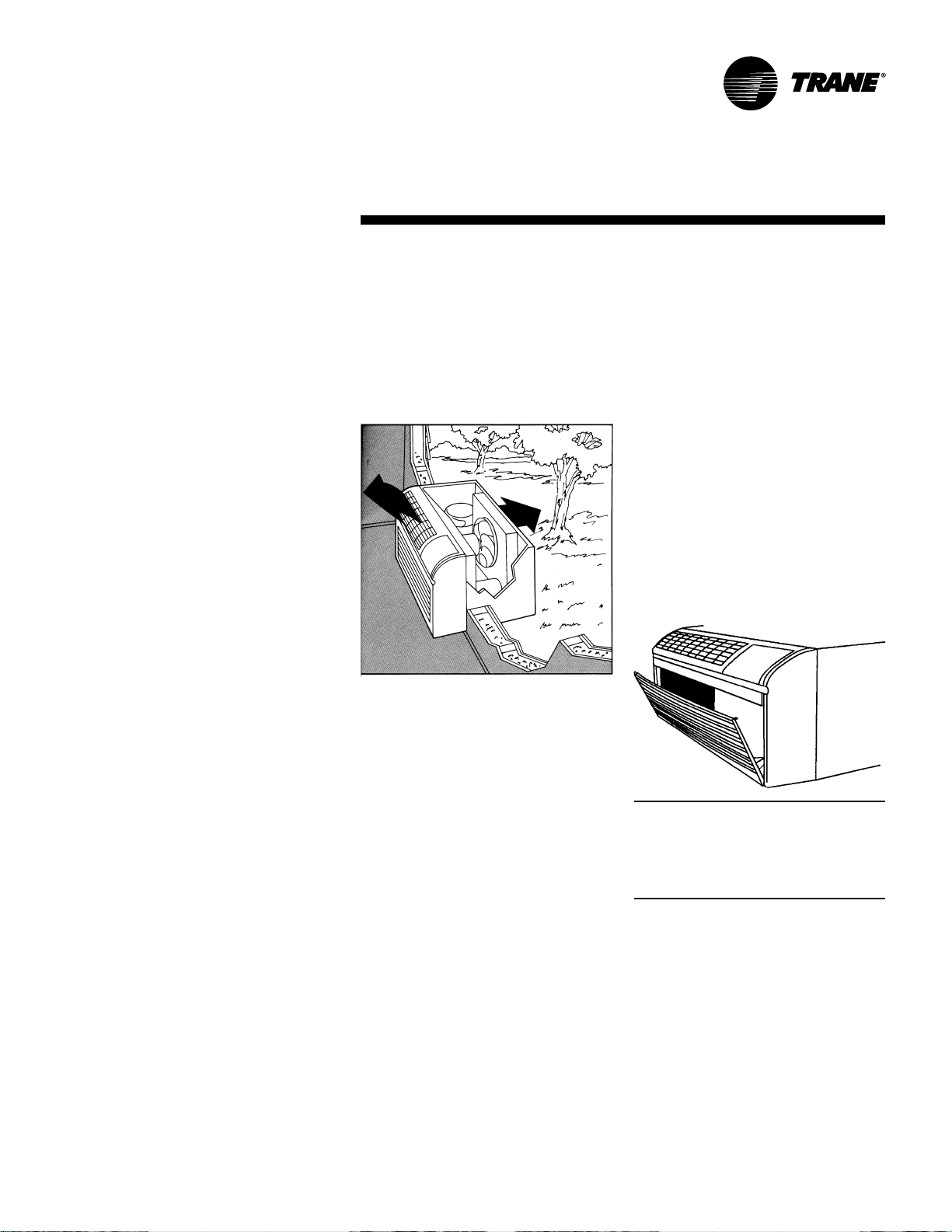
When ventilation air is filtered, rooms
stay cleaner, longer. The hidden
ventilation air intake filters outside air to
reduce dust and pollen.
User -F r iendly Contr ols
Controls are easy to read, understand
and activate.
PTAC-PRC00 1 -EN4
Features and
Benefits
Remote Thermostat Control
Each unit is built to be operated from a
remote-mounted thermostat, if desired.
Even if it is started without a remote, a
built-in low voltage power source can
accommodate a large variety of
thermostat choices — manual, auto
changeover or programmable — at a
later date.
Remote T emperature Sensing
Occupants enjoy ultimate comfort with
consistent climate control. Attach an
optional, inexpensive remote thermistor
temperature sensing device and
temperatures are held more closely to
the chosen room set ting.
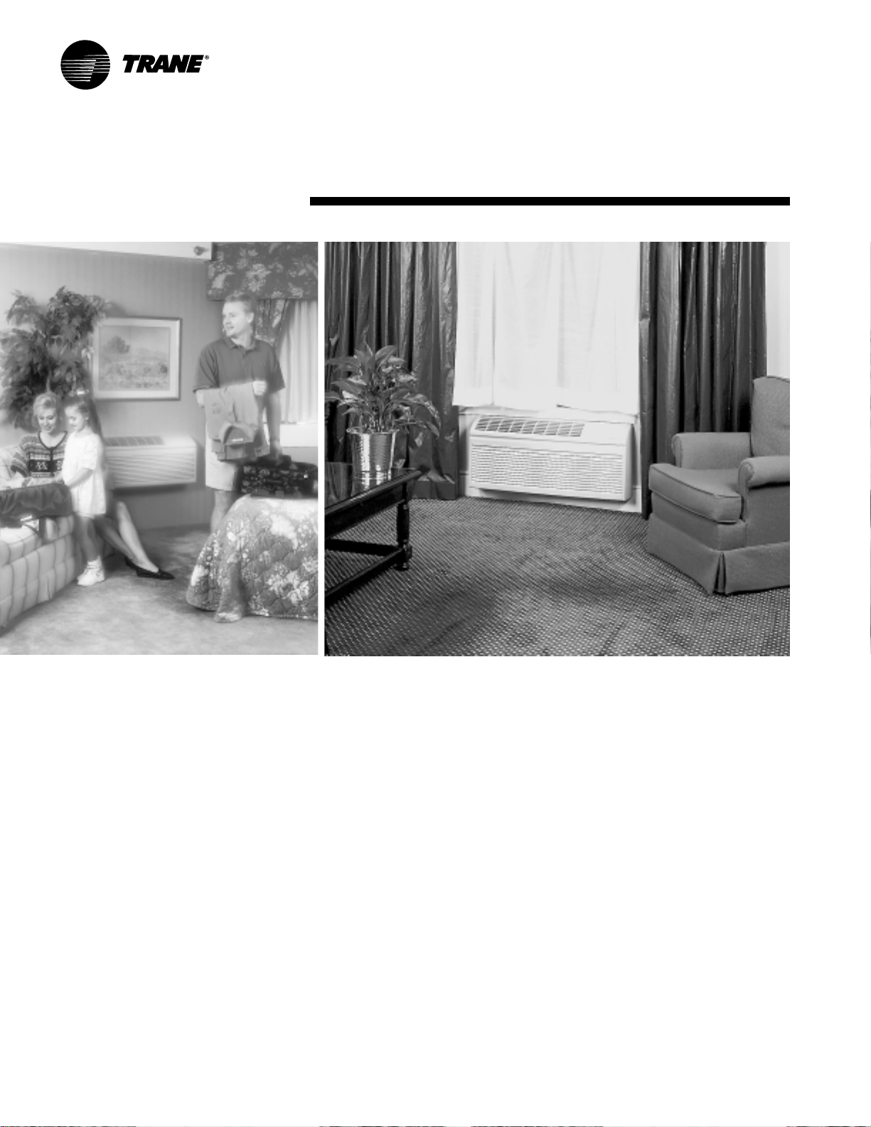
Attractive and Compact Design
The unit front has a sleek seven-inch
depth, one of the shallowest silhouettes
in the industry today. To inhibit
tampering, the front can be secured to
the chassis with hidden screws.
Our unit’s new stylish design and neutral
color make it compatible with virtually
any room decor or arc hitectural design. It
blends into the room’s color scheme.
Special Paint Prot ection
The electrodeposition paint system on
the exterior panels assure the unit and
wall sleeve will withstand years of
moisture and atmospheric pollutants
without giving up its looks to rust and
corrosion.
Ease of Installation and Servicing
After the sleeve is in place, plug in or
directly hard-wire the unit and it is ready
to run. This unit has been designed to
replace most competitors’ units. In fact
this unit can fit into most existing
sleeves, making replacement of old or
inefficient units easy and economical.
And of course, the units may be installed
flush with the outside wall.
The main components are easily
serviced; the unit is easy to diagnose or
troubleshoot to spot potential problems.
When the filter needs to be cleaned or
replaced, the filt er access door tilts
forwar d for easy access. F or more
extensive service, the unit slides out of
the sleeve easily for full access t o all
working components.
5PTAC-PRC001-EN
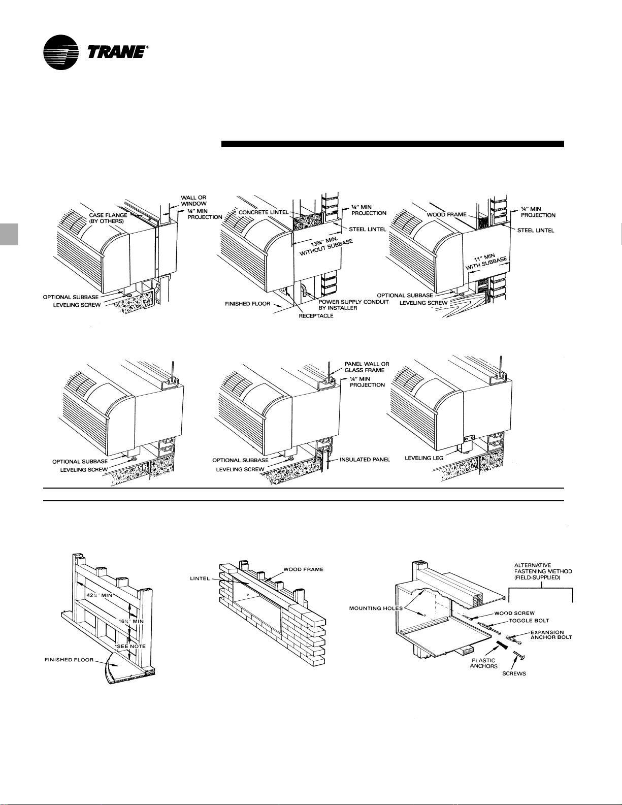
Application Considerations
Curtain Wall Installation Block and Brick Veneer Installation Frame and Bric k Veneer Installation
Optional Leveling LegPanel Wall Installation Panel Wall and Block V eneer Installation
On applications not requiring subbase or lev eling legs, unit may be flush mount ed t o floor.
Sleeve Installation Da ta
Framing for Wall Case Framing With Lintel Attaching W all Sleeve to Opening
1. 3¼” minimum with subbase.
2. On applications not requiring subbase or
leveling legs, unit may be flush mounted to floor.
PTAC-PRC00 1 -EN6

Model Number Description
MODEL NOMENCLATURE
PT E C 090 1 G * A
Digits 1,2 — Packag ed T e r minal
Air Conditioner
Digit 3 — Product T ype
E = Air Conditioner
H = Heat Pump
Digit 4 — Development Sequence
C = Third Development
Digits 5,6,7 — Unit Cooling Capacity
070 = 7,000 Btu
090 = 9,000 Btu
120 = 12,000 Btu
150 = 15,000 Btu
Notes:
1. Corrosion resistant, condensate pump, power vent units and all special units require extended ship cycles.
2. Only the following units are available from stock and can normally ship within 3 days after release.
3. Contact your local Trane representative for current stock availability and information on minimum quantity
requirements and shipping schedule for special production units.
Digit 8 — Main Pow er Supply
1 = 208-230/60/1
2 = 265/60/1
Digit 9 — Electric Heating Capacity**
0 = No Electric Heat – Air Conditioners Only
E = 2.5 kW
G = 3.5 kW (208-230V)
G = 3.7 kW (265V)
J = 5.0 kW*
Digit 10 — Design Sequence
Digit 1 1— Miscellaneous
A = Standard
B = Power Vent
C = Corrosion Resistant
D = Condensate Pump
H = Hydronic Chassis
F = Hydronic with Power Vent and Door
G = Hydronic with Power Door
J = Power Door
K = Condensate Pump with Power Vent
L = Condensate Pump with Power Door
Stock Style Models
PTEC0701GCA
PTEC0901GCA
PTEC120 1GCA
PTEC150 1GCA
PTEC150 1JCA
PTHC0701GCA
PTHC0901GCA
PTHC120 1GCA
PTHC150 1GCA
PTHC150 1JCA
PTEC0902GCA
PTHC0902GCA
PTEC1202GCA
PTHC1202GCA
PTEC1502GCA
PTHC1502GCA
*Sizes 09, 12 and 15 only.
**All heat pump units must have electric coils.
7PTAC-PRC001-EN
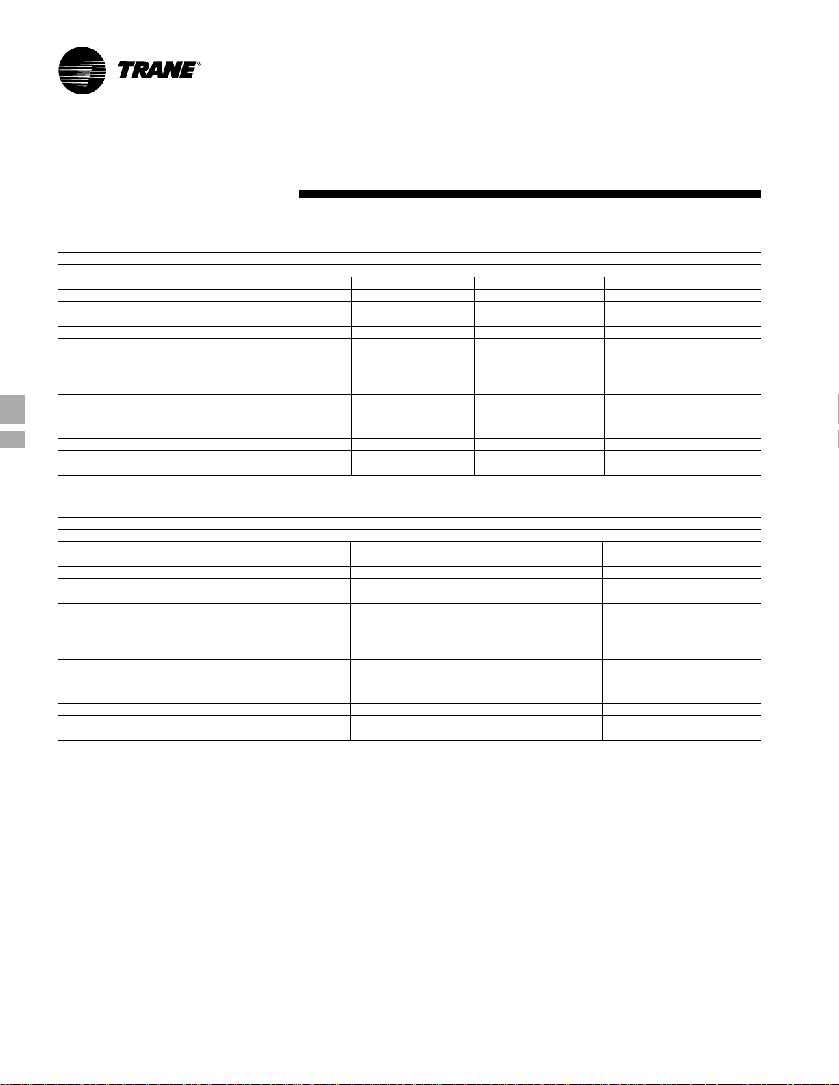
P erformance Data
Table PD-1 — Cooling Performance — Air Conditioner with Electr ic Heat Models
Model Type Air Conditioner
Model No.
Voltage
Capacity (Btu)
Amps 3.0 2.8 2.3 3.8 3.7 3.0 5.0 5.0 4.3 6.9 6.9 5.9
Watts 600 610 610 785 805 805 1 110 11 10 1130 1520 1545 1525
EER 1 1.6 11.6 1 1.6 11.3 1 1.3 11.3 10.7 10.7 1 0.7 9.2 9.2 9.3
Unit without Electric Heater
Min. Circuit/Ampacity
cfm (cool, wet coil)
cfm (dry coil)
Ventilated Air, cfm (fan only) 65* 65* 65* 65* 65* 65* 70* 70* 70* 70* 70* 70*
Dehumidification (pints/hr.) 1.6 1.6 1.6 2.6 2.6 2.6 3.5 3.5 3.5 4.4 4.4 4.4
Net wt. (approximate lbs.) 90 90 90 95 95 95 105 105 105 11 0 1 10 110
Shipping wt. (approximate lbs.) 105 105 105 110 11 0 110 120 120 120 125 125 125
* 95 cfm with optional power vent kit. Actual vent cfm performance will vary due to application and installation conditions.
Table PD-2 — Cooling Performance —Heat Pump with Electric Heat Models
Model Type Heat Pumps
Model No.
Voltage
Capacity(Btu)
Amps 3.0 2.8 2.3 3.8 3.5 3.0 5.0 4.6 4.3 6.9 6.3 5.9
Watts 610 615 615 785 805 805 1 110 1 120 1120 1485 1505 1505
EER 1 1.5 11.5 1 1.5 11.2 1 1.2 11.2 10.7 10.7 10.7 9.3 9.3 9.3
Unit without Electric Heater
Min Circuit/Ampacity
cfm (cool, wet coil)
cfm (dry coil)
Ventilated Air, cfm (fan only) 65* 65* 65* 65* 65* 65* 70* 70* 70* 70* 70* 70*
Dehumidification (pints/hr.) 1.6 1.6 1.6 2.6 2.6 2.6 3.5 3.5 3.5 4.4 4.4 4.4
Net wt. (approximate lbs.) 95 95 95 100 100 100 11 0 110 11 0 115 115 115
Shipping wt. (approximate lbs.) 11 0 110 110 115 115 115 125 125 125 130 130 130
*95 cfm with optional power vent kit. Actual vent cfm performance will vary due to application and installation conditions.
Notes:
1. All 265 volt models must use Trane’s subbase or Trane’s hard-wire junction box kit.
2. Minimum branch circuit ampacity ratings conform to the National Electric Code. However, local codes should apply.
3. Minimum voltage on 208/230 volt models is 197 volts; maximum is 253 volts. Minimum voltage on 265 volt models is 238.5 volts; maximum is 291.5 volts.
4. Overcurrent protection for all units without electric heaters is 15 amps. Overcurrent protection on 265 volt models must be cartridge-style time delay fuses (included and
5. Minimum operating ambient = 45°F.
6. Certified in accordance with the Unitary Air-Conditioner Equipment certification program, which is based on ARI standard 310/380.
EER — Energy Efficiency Ratio per American Refrigeration Institute (ARI) Test Procedures.
COP — Coefficient of Performance per ARI Test Procedures.
1 & 5
3
6
2 & 4
High 240 245 245 240 245 245 325 315 325 315 325 325
Low 205 220 220 205 220 220 250 220 250 220 250 250
High 260 265 265 260 265 265 345 335 345 335 345 345
Low 215 230 230 215 230 230 265 235 265 235 265 265
1 & 5
3
6
2 & 4
High 240 245 245 240 245 245 315 325 325 315 325 325
Low 205 220 220 205 220 220 220 250 250 220 250 250
High 260 265 265 260 265 265 335 345 345 335 345 345
Low 215 230 230 215 230 230 235 265 265 235 265 265
factory installed on Trane chassis). Note: All heat pump units must have electric coils.
PTEC 07 PTEC 09 PTEC 12 PTEC 15
208 230 265 208 230 265 208 230 265 208 230 265
7000 71 00 7100 8900 9100 9100 11900 12000 12000 1 4000 14200 14200
4.0 4.0 3.6 5.1 5.1 4.4 6.4 6.4 6.4 8.4 8.4 7.4
PTHC 07 PTHC 09 PTHC 12 PTHC 15
208 230 265 208 230 265 208 230 265 208 230 265
7000 7100 7100 8800 9000 9000 11 800 12000 12000 13800 14000 14000
4.0 4.0 3.6 5.1 5.1 4.4 7.3 7.3 5.7 8.4 8.4 7.4
PTAC-PRC00 1 -EN8

P erformance
Data
Table PD-3 — Heat Pump Reverse Cycle Heating Capacity (Btu)
Model No.
Voltage
Amps 3.0 2.6 2.2 3.6 3.2 2.6 5.1 4.5 3.9 6.3 5.7 5.4
Wat ts 550 570 570 730 740 740 1000 1020 1020 1380 1390 1390
Btu
COP
cfm (dry) 230 235 235 230 235 235 290 310 310 335 345 345
Heating2 Btu °F
Outdoor Ambient 62 8200 8400 8400 1 0200 10300 10300 13000 13200 13200 16300 16400 16400
Rating Point (COP) 3.3 3.3 3.3 3.2 3.2 3.2 3.1 3.1 3.1 2.8 2.8 2.8
2
Watts 62 730 745 745 935 940 940 1230 1245 1245 1705 1715 1715
Outdoor Ambient 57 675 690 690 880 890 890 1150 1 170 1 170 1600 1610 1610
Notes:
1. All 265 volt models must use Trane’s subbase or Trane’s hard-wire junction box kit.
2. Heating capacity and efficiency is based on unit operation without condensate pump. Unit automatically switches to electric heat at 25°F outdoor coil temperature.
1
3
2
2
57 7600 7800 7800 9600 9700 9700 12200 12400 12400 15300 15400 15400
52 6900 7100 7100 8900 9000 9000 11400 11600 11600 14200 14300 14300
47 6200 6400 6400 8000 8100 8100 10600 10800 10800 13200 13300 13300
42 5500 5700 5700 7200 7300 7300 9800 10000 10000 12200 12300 12300
37 4900 5100 5100 6400 6500 6500 9000 9200 9200 11200 11300 11300
32 4300 4500 4500 5600 5700 5700 8200 8400 8400 10100 10200 10200
52 610 630 630 815 825 825 1075 1095 1095 1485 1495 1495
47 550 570 570 730 740 740 1000 1020 1020 1380 1390 1390
42 490 505 505 660 670 670 925 945 945 1275 1285 1285
37 435 450 450 585 595 595 850 870 870 1170 1180 1180
32 380 400 400 510 520 520 775 795 795 1055 1065 1065
Depending upon relative humidity conditions, this will occur at approximately 35 degrees outdoor ambient temperature.
PTHC 07 PTHC 09 PTHC 12 PTHC 15
208 230 265 208 230 265 208 230 265 208 230 265
6200 6400 6400 8000 8100 8100 1 0600 10800 10800 13500 13300 13300
3.3 3.3 3.3 3.2 3.2 3.2 3.1 3.1 3.1 2.8 2.8 2.8
9PTAC-PRC001-EN

P erformance
Data
Table PD-4 — PTEC Air Conditioner — 208V
WBT Ent DBT Ent Outdoor T emperature (°F)
Nominal Indoor Indoor 85 95 105 1 15
Unit Coil Coil Total Sen % T otal Sen % T otal Sen % Total Sen %
Size (°F) (°F) Btu Btu SH Btu Btu SH Btu Btu SH Btu Btu SH
61 80 6930 6930 100 6665 6665 100 6270 6270 100 5980 5980 1 00
07 67 80 7345 5385 73 *7000 5250 75 6660 5295 80 6270 5175 83
73 80 8245 3980 48 7875 3850 49 7415 3845 52 7010 3710 53
61 80 8335 7390 89 7905 7165 91 7435 6930 93 7050 7050 1 00
09 67 80 9410 6240 66 *8900 5820 65 8355 5610 67 7795 5335 68
73 80 10585 4790 45 10020 4580 46 9420 4365 46 8795 4145 47
61 80 11220 10210 91 10575 9890 94 9815 9525 97 9110 9110 100
12 67 80 12630 8330 66 *11 900 8025 67 111 15 7705 69 10200 7370 72
73 80 14260 6520 46 13460 6230 46 12640 5930 47 11630 5575 48
61 80 13140 11930 91 12345 11515 93 11 395 11045 97 107 60 10760 100
15 67 80 14845 9745 66 *14000 9375 67 13020 8975 69 11990 8575 72
73 80 16780 7655 46 15870 7315 46 14835 6905 47 13635 6445 47
*These capacities are based on ARI rating point 80/67 entering air temperature, 95°F outdoor ambient.
75 6680 5695 85 6380 5545 87 6030 5665 94 571 0 5530 97
85 7205 7205 100 7030 7030 100 6745 6745 100 6320 6320 1 00
75 7440 4005 54 7155 4140 58 6680 4150 62 6290 4000 64
85 7390 6570 89 7105 6445 91 6690 6270 94 6330 6330 100
75 8335 2835 34 7885 2800 36 7485 2665 36 7070 2520 36
85 8150 5285 65 7750 4995 64 7345 4845 66 6940 4705 68
75 8385 6285 75 7940 6065 76 7460 5830 78 6960 5600 80
85 8480 8480 100 8130 8130 100 7765 7765 100 7345 7345 1 00
75 9510 501 0 53 9075 4810 53 8465 4610 54 7900 4510 57
85 9255 7295 79 8825 7165 81 8210 6890 84 7680 6470 84
75 1 071 0 3705 35 10135 3490 34 9555 3280 34 8935 3060 34
85 10450 5875 56 9880 5665 57 9270 5445 59 8640 5230 61
75 11265 8715 77 10610 8410 79 9875 8070 82 9000 7675 85
85 11505 11505 1 00 10965 10965 100 10300 10300 100 9605 9605 100
75 12770 6910 54 12205 6670 55 11320 6305 56 10440 5950 57
85 12425 9815 79 11805 9560 81 10905 9215 85 9980 8875 89
75 14435 5060 35 13645 4765 35 12840 4470 35 11 925 4145 35
85 14070 7985 57 13290 7700 58 12370 7400 60 11350 7020 62
75 13245 10205 77 12490 9830 79 11570 9405 81 10610 8940 84
85 13465 13465 1 00 12775 12775 100 11 965 1 1965 100 11 325 11325 100
75 15035 8120 54 14365 7835 55 13280 7345 55 12200 6875 56
85 14575 1 1 455 79 13785 111 25 81 12670 10680 84 11790 10370 88
75 16875 5915 35 16120 5625 35 15130 5260 35 14010 4790 34
85 16535 9330 56 15595 8970 58 14530 8610 59 13385 8225 61
PTAC-PRC00 1 -EN10

Table PD-5 — PTEC Air Conditioner — 230/265V
P erformance
Data
Nominal Indoor Indoor 85 95 105 1 15
*These capacities are based on ARI rating point 80/67 entering air temperature, 95°F outdoor ambient.
WBT Ent DBT Ent Outdoor Temperature (°F)
Unit Coil Coil Total Sen % T otal Sen % T otal Sen % Total Sen %
Size (°F) (°F) Btu Btu SH Btu Btu SH Btu Btu SH Btu Btu SH
61 80 7030 7030 100 6765 6765 100 6370 6370 100 6080 6080 100
07 67 80 7445 5485 74 *7100 5350 75 6760 5395 80 6370 5275 83
73 80 8345 4080 49 7975 3950 50 7515 3945 52 7110 3810 54
61 80 8535 7590 89 8105 7365 91 7635 7130 93 7250 7250 1 00
09 67 80 9610 6440 67 *9100 6020 66 8555 5810 68 7995 5535 69
73 80 10785 4990 46 10220 4780 47 9620 4565 47 8995 4345 48
61 80 11320 10310 91 10675 9990 94 9915 9625 97 9210 9210 100
12 67 80 12730 8430 66 *12000 8125 68 11 215 7805 70 10300 7470 73
73 80 14360 6620 46 13560 6330 47 127 40 6030 47 11730 5675 48
61 80 13340 12130 91 12545 1 171 5 93 11 595 11245 97 10960 10960 100
15 67 80 15045 9945 66 *14200 9575 67 13220 9175 69 12190 8775 72
73 80 16980 7855 46 16070 7515 47 15035 7105 47 13835 6645 48
75 6780 5795 85 6480 5645 87 6130 5765 94 5810 5630 97
85 7305 7305 100 7130 7130 100 6845 6845 100 6420 6420 100
75 7540 4105 54 7255 4240 58 6780 4250 63 6390 4100 64
85 7490 6670 89 7205 6545 91 6790 6370 94 6430 6430 100
75 8435 2935 35 7985 2900 36 7585 2765 36 7170 2620 37
85 8250 5385 65 7850 5095 65 7445 4945 66 7040 4805 68
75 8585 6485 76 8140 6265 77 7660 6030 79 7160 5800 81
85 8680 8680 100 8330 8330 100 7965 7965 100 7545 7545 100
75 9710 5210 54 9275 50 10 54 8665 4810 56 8100 4710 58
85 9455 7495 79 9025 7365 82 841 0 7090 84 7880 6670 85
75 10910 3905 36 10335 3690 36 9755 3480 36 9135 3260 36
85 10650 6075 57 10080 5865 58 9470 5645 60 8840 5430 61
75 11365 8815 78 1071 0 8510 79 9975 8170 82 9100 7775 85
85 11605 11605 100 11 065 11065 100 10400 10400 100 9705 9705 100
75 12870 7010 54 12305 6770 55 11 420 6405 56 10540 6050 57
85 12525 9915 79 11905 9660 81 11 005 9315 85 10080 8975 89
75 14535 5160 36 13745 4865 35 12940 4570 35 12025 4245 35
85 14170 8085 57 13390 7800 58 12470 7500 60 11 450 7120 62
75 13445 10405 77 12690 10030 79 11770 9605 82 10810 9140 85
85 13665 13665 100 12975 12975 100 12165 12165 100 11525 11525 100
75 15235 8320 55 14565 8035 55 13480 7545 56 12400 7075 57
85 14775 11655 79 13985 11325 81 12870 10880 85 11990 10570 88
75 17075 6115 36 16320 5825 36 15330 5460 36 14210 4990 35
85 16735 9530 57 15795 9170 58 14730 8810 60 13585 8425 62
11PTA C-PRC001 -EN

Table PD-6 — PTHC Heat Pump — 208V
P erformance
Data
Nominal Indoor Indoor 85 95 105 1 15
*These capacities are based on ARI rating point 80/67 entering air temperature, 95°F outdoor ambient.
WBT Ent DBT Ent Outdoor Temperature (°F)
Unit Coil Coil Total Sen % T otal Sen % T otal Sen % Total Sen %
Size (°F) (°F) Btu Btu SH Btu Btu SH Btu Btu SH Btu Btu SH
61 80 6930 6930 100 6665 6665 100 6270 6270 100 5980 5980 100
07 67 80 7345 5385 73 *7000 5250 75 6660 5295 80 6270 5175 83
73 80 8245 3980 48 7875 3850 49 7415 3845 52 7010 3710 53
61 80 8225 7175 87 7785 6945 89 7315 6705 92 6810 6790 100
09 67 80 9305 5890 63 *8800 5660 64 8250 5485 66 7675 5170 67
73 80 10480 4705 45 9920 4495 45 9315 4275 46 8690 4050 47
61 80 1 1120 10 110 91 1 0475 9790 93 9715 9425 97 9010 9010 100
12 67 80 12530 8230 66 *1 1800 7925 67 1 1 015 7605 69 10100 7270 72
73 80 14160 6420 45 13360 6130 46 12540 5830 46 11530 5475 47
61 80 12955 11755 91 12170 11350 93 1 1 230 10885 97 10605 10605 100
15 67 80 14635 9605 66 *13800 9240 67 12830 8845 69 11820 8450 71
73 80 16540 7545 46 15645 7210 46 14625 6805 47 13440 6355 47
75 6680 5695 85 6380 5545 87 6030 5665 94 5710 5530 97
85 7205 7205 100 7030 7030 100 6745 6745 100 6320 6320 1 00
75 7440 4005 54 7155 4140 58 6680 4150 62 6290 4000 64
85 7390 6570 89 7105 6445 91 6690 6270 94 6330 6330 100
75 8335 2835 34 7885 2800 36 7485 2665 36 7070 2520 36
85 8150 5285 65 7750 4995 64 7345 4845 66 6940 4705 68
75 8290 6120 74 7840 5900 75 7350 5660 77 6855 5420 79
85 8285 8285 100 7920 7920 100 7525 7525 100 7105 7105 100
75 9420 4905 52 8960 4775 53 8360 4500 54 7785 4400 57
85 9145 7085 77 8710 6945 80 8095 6670 82 7520 6400 85
75 1 061 0 3675 35 10050 3465 34 9450 3245 34 8835 3020 34
85 10345 5730 55 9775 5520 56 9165 5300 58 8535 5075 59
75 1 1165 8615 77 10510 8310 79 9775 7970 82 8900 7575 85
85 1 1 405 11405 100 10865 10865 100 10200 10200 100 9505 9505 1 00
75 12670 6810 54 12105 6570 54 1 1 220 6205 55 10340 5850 57
85 12325 9715 79 11705 9460 81 10805 91 15 84 9880 8775 89
75 14335 4960 35 13545 4665 34 12740 4370 34 11825 4045 34
85 13970 7885 56 13190 7600 58 12270 7300 59 1 1250 6920 62
75 13055 10055 77 12310 9690 79 1 1 405 9270 81 10460 8815 84
85 13275 13275 1 00 12590 12590 100 1 1795 11795 100 11 165 1 1165 100
75 14820 8000 54 14160 7720 55 13090 7240 55 12025 6775 56
85 14370 11290 79 13585 10970 81 12485 10530 84 1 1620 10220 88
75 16635 5825 35 15890 5540 35 14915 5185 35 13810 4720 34
85 16300 9195 56 15370 8845 58 14320 8490 59 13195 8105 61
PTAC-PRC00 1 -EN12

Table PD-7 — PTHC Heat Pump — 230/265V
P erformance
Data
Nominal Indoor Indoor 85 95 105 1 15
*These capacities are based on ARI rating point 80/67 entering air temperature, 95°F outdoor ambient.
WBT Ent DBT Ent Outdoor Temperature (°F)
Unit Coil Coil Total Sen % T otal Sen % T otal Sen % Total Sen %
Size (°F) (°F) Btu Btu SH Btu Btu SH Btu Btu SH Btu Btu SH
61 80 7030 7030 100 6765 6765 100 6370 6370 100 6080 6080 1 00
07 67 80 7445 5485 74 *7100 5350 75 6760 5395 80 6370 5275 83
73 80 8345 4080 49 7975 3950 50 7515 3945 52 711 0 3810 54
61 80 8425 7375 88 7985 7145 89 7515 6905 92 701 0 6990 100
09 67 80 9505 6090 64 *9000 5860 65 8450 5685 67 7875 5370 68
73 80 10680 4905 46 101 20 4695 46 951 5 4475 47 8890 4250 48
61 80 11320 1 0310 91 10675 9990 94 9915 9625 97 9210 9210 100
12 67 80 12730 8430 66 *12000 8125 68 1121 5 7805 70 10300 7470 73
73 80 14360 6620 46 13560 6330 47 12740 6030 47 11730 5675 48
61 80 13155 1 1955 91 12370 11550 93 11430 11 085 97 10805 10805 100
15 67 80 14835 9805 66 *14000 9440 67 13030 9045 69 12020 8650 72
73 80 167 40 7745 46 15845 7410 47 14825 7005 47 13640 6555 48
75 6780 5795 85 6480 5645 87 6130 5765 94 5810 5630 97
85 7305 7305 100 7130 7130 100 6845 6845 100 6420 6420 1 00
75 7540 4105 54 7255 4240 58 6780 4250 63 6390 4100 64
85 7490 6670 89 7205 6545 91 6790 6370 94 6430 6430 100
75 8435 2935 35 7985 2900 36 7585 2765 36 7170 2620 37
85 8250 5385 65 7850 5095 65 7445 4945 66 7040 4805 68
75 8490 6320 7 4 8040 6100 76 7550 5860 78 7055 5620 80
85 8485 8485 100 8120 8120 100 7725 7725 100 7305 7305 1 00
75 9620 5105 53 9160 4975 54 8560 4700 55 7985 4600 58
85 9345 7285 78 8910 7145 80 8295 6870 83 7720 6600 85
75 10810 3875 36 10250 3665 36 9650 3445 36 9035 3220 36
85 10545 5930 56 9975 5720 57 9365 5500 59 8735 5275 60
75 11365 8815 78 10710 8510 79 9975 8170 82 9100 7775 85
85 11605 11605 100 1 1065 11065 100 10400 10400 100 9705 9705 100
75 12870 7010 54 12305 6770 55 11420 6405 56 10540 6050 57
85 12525 9915 79 11905 9660 81 11005 9315 85 10080 8975 89
75 14535 5160 36 13745 4865 35 12940 4570 35 12025 4245 35
85 14170 8085 57 13390 7800 58 12470 7500 60 11450 7120 62
75 13255 10255 77 12510 9890 79 11605 9470 82 10660 9015 85
85 13475 13475 100 12790 12790 100 11995 11995 100 1 1 365 11365 100
75 15020 8200 55 14360 7920 55 13290 7440 56 12225 6975 57
85 14570 11490 79 13785 11170 81 1 2685 10730 85 1 1820 10420 88
75 16835 6025 36 16090 5740 36 15115 5385 36 1401 0 4920 35
85 16500 9395 57 15570 9045 58 14520 8690 60 13395 8305 62
13PTA C-PRC001 -EN

P erformance
Data
Table PD-8 — Heating Capacity — W ater
Pressure 7000 & 9000 Btu Units 12000 Btu Units 15000 Btu Units
Drop
(psig) 200°F EWT 180°F EWT 200°F EWT 180°F EWT 200°F EWT 180°F EWT
gpm Coil Valve Hi Lo Hi Lo Hi Lo Hi Lo Hi Lo Hi Lo
1 .00 0.93 0.19 14910 13388 12639 11186 16945 14387 14257 12152 17858 15534 15049 1 3312
1 .1 3 1 .03 0.24 15216 13706 12898 11452 17360 14689 14607 12407 18276 15955 1540 1 13672
1 .25 1.1 4 0.30 15500 13997 13139 1 1696 17745 14968 14930 12642 18666 16338 15729 14001
1 .38 1 . 26 0.36 15762 14262 13361 11917 18099 15222 15228 12858 1 9025 16684 16032 14297
1 .50 1 .40 0.43 16003 14501 13565 12117 18423 15454 15501 13053 19356 16991 16311 14561
1.63 1 .55 0.50 *16222 1471 4 13751 12295 18717 15661 15748 13228 19658 17261 16565 14792
1 .75 1 . 71 0.58 16420 14900 13919 12450 18980 15845 15969 13384 1 9930 17494 16794 14991
1 .88 1 .89 0.66 16596 15061 14068 12584 19212 16006 16165 13519 201 73 17689 16999 15158
2.00 2.10 0.76 16751 15195 141 99 12696 *19268 16142 16212 13635 20387 17846 17179 15293
2.13 2.32 0.85 16884 15302 1 4312 12786 19586 16255 16479 13730 *20445 17965 17229 15395
2.25 2.57 0.96 16995 15384 14407 12854 19727 16345 16598 13806 20727 18047 1 7466 15465
2.38 2.84 1.07 17085 15439 14483 12900 19838 16410 16691 13861 20853 18091 17572 15503
2.50 3.14 1.18 17154 15467 14541 12924 19919 16452 16759 13897 20950 18097 17654 15508
2.63 3.48 1.30 17201 15470 14581 12926 19968 16471 16801 13912 210 18 18065 1771 1 15481
2.75 3.85 1.43 17226 15505 14603 12956 19988 16580 1681 7 14004 21056 18140 17744 15545
*Based on ARI Rating Conditions of 70°F Entering Air Temp., 200°F Entering Water Temp and 180°F Leaving Water Temp.
Max Water Temperature 200°F Max. Water Pressure - 200 psig.
2-Way Fan Speed F an Speed Fan Speed Fan Speed Fan Speed F an Speed
Heating Capacity (Btu) Hot Water
Table PD-9 — Heating Capacity — Steam
7,000 & 9,000 Btu Units 12,000 Btu Units 15,000 Btu Units
Steam Fan Speed Fan Speed Fan Speed
PSIG High Low High Low High Low
2 20,236 17,816 21,694 18,306 23,709 —
3 20,686 18,253 22,100 19,003 25,676 21,099
4 20,821 18,544 22,822 19,313 26,325 23,678
PTAC-PRC00 1 -EN14

Electric Power
Table EP-1 — Electric Heat Capacity and Electrical D ata (F or PTEC and PTHC Models)***
Electric Nominal Heating Minimum Circuit Overcurrent
2
Voltage
208/230 2.0/2.5 1 6,800 8,500 — 2,140/2,650 10.2/11.5 14.2 15 6-15 P
208/230 2.9/3.5 1 9,900 12,000 — 3,040/3,650 14.5/15.8 19.6 20 6-20 P
208/230 4.1/5.0 ** 14,000 17,100 — 4,240/5,150 20.3/22.3 27.7 30 6-30 P
265 2.5 1 — — 8,500 2,650 1 0 12.4 15 7-20 P
265 3.7 1 — — 12,600 3,850 14.6 18.1 20 7-20 P
265 5.0 ** — — 17,100 5,150 19.5 24.2 25 7-30 P
Notes:
1. Minimum branch circuit ampacity ratings conform to the National Electric Code. However, local codes should apply.
2. Minimum voltage on 208/230 volt models is 197 volts; maximum is 253 volts. Minimum voltage on 265 volt models is 238.5 volts; maximum is 291.5 volts.
3. Overcurrent protection for all units without electric heaters is 15 amps. Overcurrent protection on 265 volt models must be cartridge-style time delay fuses (included and
factory installed on Trane chassis).
4. Total watts for 7,000 and 9,000 Btu models; add 40 watts for size 12 and 70 watts for size 15.
**PTHC07, 09 and 12 are two-stage; PTHC15 is one-stage.
*** Note: All heat pumps must have electric coils.
Table EP-2 — Pow er Receptacle Configurations
Voltage 208/230 265
Unit Supplied Plug
Heater No. Of T otal T otal Power
Size (kW) Stages Btu 208 Btu 230 Btu 265 Watts
4
Amps Ampacity1Protection
3
Cord
Amps 1 5 20 30 20 30
NEMA Rating 6-15P 6-20P 6-30P 7-20P 7-30P
Receptacle
Amps 20 20 30 20 30
NEMA Rating 6-20R 6-20R 6-30R 7-20R 7-30R
Notes:
1. All wiring, including receptacles, must be made in accordance with local electrical codes and regulations.
2. NEMA 6-15 and 6-20 plugs fit in NEMA 6-20 receptacles.
3. Receptacles shown for 208/230 applications are factory supplied with subbase, per local codes for wall mounted receptacles use or the corresponding NEMA receptacles.
4. Receptacles shown for 265 volt applications are factory supplied with subbase. Codes do not allow 265 volt units to mate with wall mounted receptacles. They may however be
hard-wired per Local Codes.
15PTA C-PRC001 -EN

Unit with Wall Sleeve and Subbase Accessory
Dimension and Weights
T op View
Front View
Notes:
1. Allow a minimum of 31/4” clearance between cabinet and floor to permit installation of options subbase.
2. Allow minimum of 3” clearance between cabinet and side walls to permit front panel removal.
3. Drain tube can be mounted either right side, left side or bottom of sleeve. Bottom drain to be located by customer. Drain kit shipped separate.
4. Unit provides 20 percent outside air.
5. Detachable cord ships attached to unit. Cord can be removed for direct attachment of building wiring or wiring from junction box kit.
6. For U.S. approval — 265 volt units and units with duct packages must have permanent wiring connection. Permanent wiring requirement can be met either by supplying
afull length subbase for concealed cord connection or by direct wiring with junction box kit.
7. Control door provided on standard unit for access to controls.
Right Side View
PTAC-PRC00 1 -EN16

Dimension and
Weights
Field Supplied Extension
17PTA C-PRC001 -EN

Hydronic Heat Kit
NOTE: W all sleeve must
extend exactly 3 inches
from finished interior
wall
Dimension and
Weights
Notes:
1. This kit completely encloses all plumbing and coils, but still allows easy access to controls.
2. The chassis can slide out for easy service without removing hydronic plumbing.
3. The kits feature left or right-hand piping.
4. Unit retains complete service access with kit installed.
PTAC-PRC00 1 -EN18

Dimension and
Weights
Duct Pack age
When two adjacent rooms need to be conditioned, a main duct kit and a duct extension kit are possible options. These kits transfer
air from one room to another, yet allow different air flows for the rooms (airflow distribution can be adjusted from
65/45 to 80/20.)
Front View
Duct T ermination Kit
The Duct Termination Kit
includes a grille and a
sleeve for fit ting duct or
duct extension through
the wall.
19PTA C-PRC001 -EN

Mec hanical Specifications
Unit Chassis
Each unit will be slide-out design shipped
with room cabinet front installed. Unit
chassis will have the ability to be installed
with zero reversing clearance from
finished floor. An electrical power cord
will be included with chassis and
installed by the manufacturer to assure
proper NEMA 6 or 7 configuration and
UL approved length. Unit will be tested
for conformance to AS TME w ater
infiltration specification AS TME 331 -86
which assures no water infiltration when
tested at eight inches of rain per hour at
63 mph wind for 15 minutes.
Room Cabinet/Front P anel
The room cabinet/front panel will have
sloped discharge so that obstructions are
not placed on unit. The discharge
conditioned air can be directed into the
room at an angle of 15 to 40 degrees
from the vertical position. The discharge
grille will be a polycarbonate material to
resist bending, cracking, rusting and
corrosion. The front panel will be able to
be field secured to chassis to inhibit
tampering. Cabinet depth will be seveninch to minimize unit’s impact on room
space.
Filter
The filter will be accessible without
removing room front. Filter material will
be nylon mesh, permanent cleanable.
Condenser/Evaporat or F ans
One direct drive with a permanent split
capacitor two-speed motor. The
condenser fan will be propeller type and
the indoor evaporator fan will be a
centrifugal blower type.
Cooling Condensate Remov al
High humidity conditions may call for
condensate removal system. The
outdoor fan diffuses water directly on to
the outdoor condenser coil for rapid
evaporation and increased cooling
efficiency .
Compressor
The compressor will be hermetically
sealed, internally isolated, rotary-type
and permanently mounted on rubber
isolators. No removal or adjustment of
compressor hold down bolts will be
required during installation.
Coils
Coils will have rifled copper tubing
expanded into rippled-edge louvered
aluminum fins.
Heat Pumps
Heat pumps will include a changeover
thermostat that senses an outside coil
switch-over temperature of 25°F,
lock-open refrigerant valve during heat
pump operation, temperature-activated
defrost drain and automatic emergency
heat operation to override the heat
pump’s changeover thermostat and
bring on electric resistance heaters in the
event of a sealed system failure. Unit will
not operate compressor and electric
heaters simultaneously.
Outside Air Damper/V ent Control
The vent control will allow 65 to 70 cfm
of fresh air to be drawn into the room.
This fresh air can provide ventilation
when the blower is operating. T o obtain
access to the vent control, remove the
cabinet front. The vent control lever is on
the left side of the c hassis. The control
lever must be rotated to either open or
close the damper. Actual vent cfm
performance will vary due to application
and installation conditions.
Filtered Outdoor Air Intake
The outdoor air intake will be filtered
with a talc-filled polypropylene filter that
will reduce dust from coming into the
room.
Paint System Cor r osion Pr otection
All units are built with hot-dipped
galvanized steel. Metal parts are then run
through a six-stage zinc phosphate
cleaner/pretreatment, painted with a
cathodic electroplating of an epoxy resin
paint and baked for 20 minutes at 350°F.
All exterior parts that are exposed to
sunlight get an additional coating of
polyester and are baked for 20 minutes
at 350°F for additional protection from
the fading effects of ultraviolet rays. This
paint process makes the unit highly
resistant to normal rust, corrosion and
fading. It is the best paint process in the
industry today.
Corrosion-Resistant Chassis (Standar d Option)
The condenser coil is painted using
cathodic electrocoat. The bottom ¼ of the
compressor is coated with a water borne
resin. The outdoor side of interior parts
are top coated, in addition, the base pan
is cathodic electrocoated.
PTAC-PRC00 1 -EN20

Mec hanical
Specifications
Unit Controls
The unit controls will be full solid-state
and accessible from the top. The
standard unit mounted controls will
include two rotary (switch) knobs
controlling unit operational and
temperature mode. The unit operational
switch includes:
• Off position.
• Fan only — unit operates on low fan
speed.
• Low cool — unit operates on low fan
speed to circulate air for cooling.
• High cool — unit operates on high fan
speed to circulate air for cooling.
• Low heat — unit operates on low fan
speed to circulate air for heating.
• High heat — unit operates on high fan
speed to circulate air for heating.
Temperature Switc h
The temperature switch is controlled by
turning the knob clockwise for a cooler
room temperature; turning it
counterclockwise will provide a w armer
room temperature. Adjusting the
thermostat to the mid setting (vertical)
will set the room temperature at
approximately 75°F.
Remote Control Operation
To operate units with remote
thermostats, the Standard/Remote unit
mounted switch must be set to the
remote position. When in the remote
position, the unit will only respond to the
wall-mounted thermostat inputs. Unit
will operate on low or high fan.
Remote Thermostat/Sensor T erminals
These terminals provide control inputs
for a remote thermostat or sensor.
Front Desk Contr ol Terminals
These terminals provide control inputs
for a front desk switch.
Load Shedding Terminals
The LS/IN terminals will provide a
connection for a switch that can be
added to close the circuit and lockout the
compressor and electric heat when the
power company or energy management
system is trying to reduce its load for a
specific time.
On Board Diagnostics
An LED light will flash a code displaying
8 conditions: Control OK, 24 Vac Fuse
Blown, ICT (Indoor Coil T emperature)
Probe Failure, Mode Switc h F ailure,
Potentiometer Failure, Bad Thermostat
Input Failure, Bad Communications in
Slave Mode, and IAT (Indoor Air
Temperature) Failure. A spare 500 MA
fuse has been provided on the board.
Temperature Limiter
The temperature limiting feature can
reduce energy costs by controlling the
maximum temperature in heating and
the minimum temperature in cooling.
Room Freez e Prot ection
Freeze protection is built into all units
and will activate the electric resistance
heater (when it senses a temperature of
40°F room temperature) to maintain an
above freezing temperature at the
sensor.
Fan Cycle S witch
The fan cycle switch sets the operational
mode of the fan. In the ON position, the
fan will run continuously whenever the
unit is in the heat or cool position. In the
AUTO position, the fan will cycle on and
off with the compressor or electric heater
when the unit is in the cool or heat
mode.
Aut omatic Emerg ency Heat Staged Thermostat
On every unit mounted control heat
pump, electric heat engages
automatically if the sealed system or
compressor fails.
Compressor Time Delay
The compressor will not try to restart
once running or until approximately
three minutes have elapsed after
shutdown.
21PTA C-PRC001 -EN

Options
Options
Wall Sleeves
Wall sleeves shall be industry standard
size of 13¾”D x 42”W x 16
Extended Wall Sleeves
Extended wall sleeves shall be industry
standard size of 18”D x 42”W x 16
or 24” D x 42”W x 16
Drain Kit
Drain kit attaches to the bot tom of the
wall sleeve for directional controlled
internal or external disposal of
condensate and defrost water.
Outdoor Grilles
Outdoor grilles are available as
architectural extruded, anodized
aluminum and four standard colors.
Special colors are also available or
standard stamped aluminum.
Condenser Baffle Kit
The condenser baffle kit is required
when replacing an existing packaged
terminal unit and/or the original outdoor
grille is not made by Trane. These baffles
are required to deflect discharge air
away from the inlet, preventing
recirculation of hot condenser air.
Leveling Legs Kit
Attaches easily to the w all sleeve for
support and accurate unit leveling on
units without subbases. Adjustable from
5/8
” to 5 ¼”.
2
Subbases
Subbases are prewired to facilitate field
electrical connections and include a
NEMA 6 or 7 configuration electrical
receptacle. The subbases include two
leveling screws for sleeve support and
accurate unit leveling during installation.
Subbases include locations for field
installation of physical disconnect
switches, cartridge-style fuse holders
and circuit breakers. Side skirts will be
included with subbases.
1/16
”H.
1/16
”H.
1/16
”H
Pow er Disconnect S witch Kit
A power disconnect switch must be
installed in hard-wire junction or
subbase for use as a physical disconnect
where required by local codes.
Circuit Breaker Kit
A circuit breaker kit is installed in the
subbase to provide overcurrent
protection for proper 208/230 volt
amperage. Can also be used as a
physical disconnect where local codes
permit 208/230 volts.
Fuse Holder Kit
Fuses are included in 265 volt units. For
208/230 volts, these kits allow fusing in
15, 20 and 30 amps. Fuses are not
included. Fuse holders must be installed
in the unit or subbase.
Hard-Wire Junction Box Kit
Provides for easy electrical connection
when permanent wiring is required.
Hard-wire kit must be used on 265 volt
units if subbases are not used.
Duct T r ansition and Ext ended Kit
A main duct transition piece will attac h to
the discharge of the unit and a duct
extension will be attached to the
transition piece to carry up to 40 percent
of the conditioned air to the adjoining
room.
Pow ered Outside V ent and Damper Kit
An optional power vent kit can be
installed to increase cfm to 95. The
power damper will automatically open
when the unit is operating and close
when not powered. Actual vent cfm
performance will vary due to application
and installation conditions.
Hydronic Heat Kit
The hydronic heat kit is a field-installed
package that can attac h to air
conditioners to provide central system
hot water or steam heat capability on top
of units. The kit includes left or right-hand
piping. The units retain complete service
access with kit installed.
Control V alves
24 volt water valves are available in
either two-way or three-way for 208/230
volt units and 265 volt units. 24 volt
steam valves are also available for
208/230 and 265 volt units.
Remote/Wall Ther mostats
Manual changeover thermostat
One-stage heat, One-stage cool and Off
Switch.
Automatic changeover thermostat with
T wo-stage Heat and One-stage Cool and
Off Switc h.
T wo-stage Heat (heat pump only) First
stage brings on electric coil when room
temperature is more than 3.8°F cooler
than thermostat setting; then electric
heat will turn off and heat pump cycles
on. Also one-stage Cool with Manual
Changeover.
T wo-stage Heat and One-stage Cool with
Manual Changeover and Programmable.
Remote T emperature Sensor
This temperature sensor overrides
standard unit mounted sensor to allow
temperature sensing on internal wall for
more accurate temperature control.
Condensate Remov al Pump —Heat Pump Only
The internal condensate pump serves as
an effective means for disposing of
condensate generated during heat pump
operation by transferring it to the indoor
coil. The warm coil surface and the warm
room air help in evaporation of the
condensate while adding humidity to the
room. As with any equipment of this
type, the addition of this kit will decrease
the sensible heating capacity of the unit.
This kit is not intended for use in
seacoast or corrosive environments.
Note: Under extreme high humidity conditions, the
internal condensate pump may not be able to dispose of
all the condensate produced, and condensate would
then drip from the outside of the wall sleeve. If this
condensation is unacceptable, then a drain system
(including factory approved drain kit for the wall sleeve)
should be installed.
Control Cov er Key Loc k Kit
Allows the owner to lock the control
panel access to prevent unauthorized
operation.
PTAC-PRC00 1 -EN22

Options
Subbase Kit
The fully skirted subbase conceals wiring
while providing strong support. A plug-in
receptacle and field wiring access
expedites installation. Electrical
accessories such as fuse holders, circuit
breakers and disconnect switches meet
N.E.C. requirements.
Fuse Holder Kit
Cartridge-style fuses can be installed in
the fuse holder for use in the subbase or
chassis. It is available in 1 5, 20 and 30
amp and included on the 265 volt unit.
Condensate Drain Kit
This kit attaches to the w all sleeve base
pan for controlled internal or external
disposal of condensate and defrost
water .
Outdoor Grilles
Outdoor grilles are available in stamped
aluminum and an attractive extruded
aluminum architectural grille.
Security Ke y Locks
The installation of T rane’s security key
locks helps prevent tampering of the
controls used to set temperature,
heating and cooling functions. Locks are
available for all PT AC models.
Deflector Baffle Kit
The kit includes two air deflection baffles.
These deflectors direct the air in toward
the center and away from the inlet to
prevent recirculation of the hot
condenser air. This kit is
when the outdoor grille is provided by
T rane.
Hard-Wire Kit
This kit is used to permanently wire to
chassis when standard subbase and
power cord are not utilized.
Circuit Breaker Kit
The circuit breaker kit, available in 15, 20,
25 or 30 amp, can be used with T rane’s
subbases. It gives overcurrent protection
and its location allows turning unit on or
off without tools.
not
to be used
Pow er Disconnect Switc h
The power disconnect switch can be
used for 265 or 208/230 volt physical
disconnect where required by local
codes. The switch is rated at 30 amp
capacity. The switch is for use with
T rane’s standard subbases or hard
wire kit.
Pow er Vent and D amper Kit
Installation of the power vent can
increase the cfm to 70. The damper will
automatically close when unit is not
powered.
Pow er Door Kit
Door will power open to allow fresh air
when the unit fan is on and spring
closed when the unit fan is off.
Remote T emperature Sensor
This sensor allows for inexpensive
temperature sensing on an internal wall
for more accurate temperature control.
23PTA C-PRC001 -EN

Warranty
W ar ranty Info r mation
Standard War ranty
•Full First-Year W arranty
T rane will repair or replace, free of
charge including labor , an y part whic h
proves to be defective due to
workmanship or materials.
•Full Fiv e-Year Sealed System
Warranty
T rane will repair or replace, free of
charge including labor , the evaporator,
condenser, compressor or connecting
tubing which proves to be defective due
to workmanship or materials.
•Limited Second thr ough Fif th Year
Warranty
During the 2nd through 5th year, Trane
will provide, free of charge, functional
parts whic h prove to be defective due to
workmanship or materials. Components
covered are switc hes, solenoids, fan
motors, thermostats, circuit boards,
factory installed heaters, blower wheel,
fan propeller and capacitor.
This limited warranty does not include
diagnostic time, labor or any
transportation and reinstallation c harges
that may be required.
PTAC-PRC00 1 -EN24
The T rane Company
An American Standard Company
www.trane.com
For more information contact your local
distributor (dealer), local district office, or
e-mail us at comfort@trane.com
Literature Order Number
File Number
Supersedes
Stocking Location
PTA C-PRC001 -EN
PL-UN-PTAC-PRC001-EN-10-00
PTA C-DS-1 6/98
Inland - La Crosse
Since The Trane Company has a policy of continuous product and product data improvement, it reserves the
right to change design and specifications without notice.
 Loading...