

Page 1
Product Catalog
Horizon™ Outdoor Air Unit Water Source Heat Pump
For 100% Outdoor Air Applications
Models: OABE, OADE, OAKE, OANE
August 20 14
OAU-PRC003A-EN
Page 2
Introduction
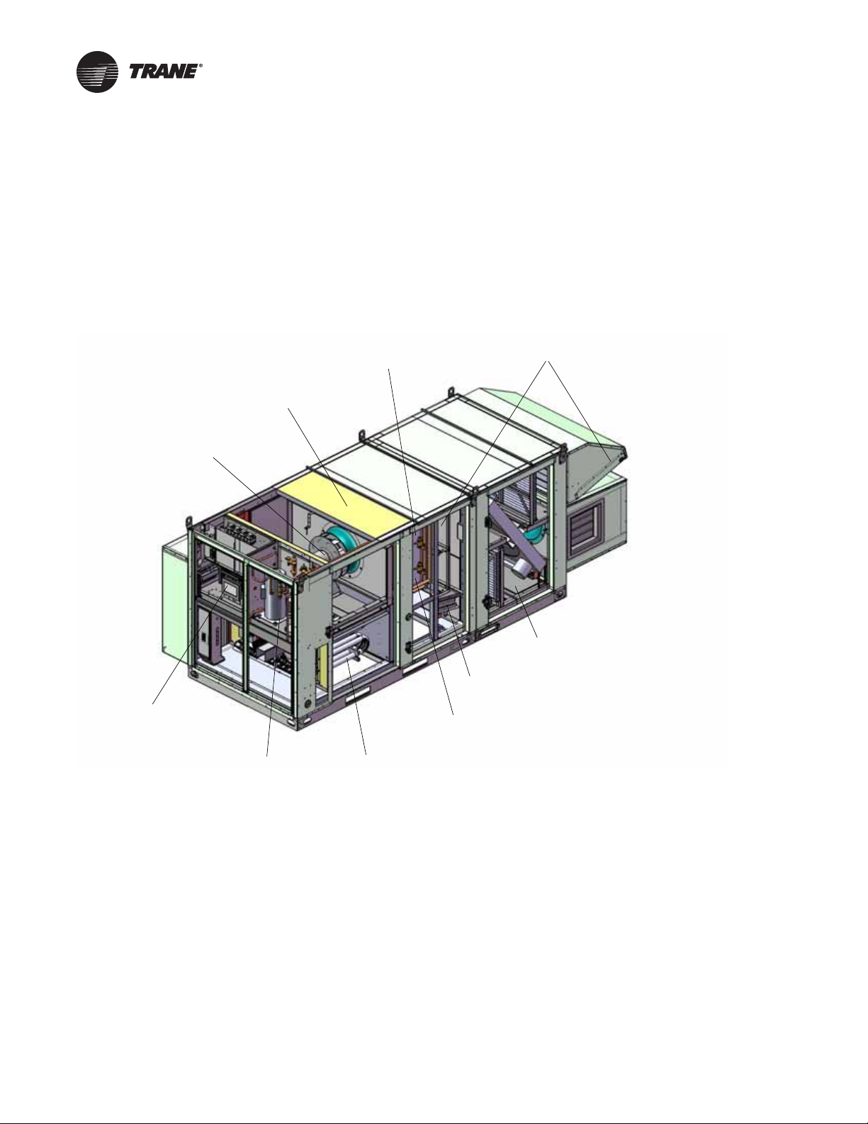
HIGH TURNDOWN INDIRECT GAS-FIRED BURNER
OPTIONAL RETURN-AIR
WITH EASY TO READ HUMAN INTERFACE
PLUS 2" MAXIMUM EXTERNAL CAPACITY
DAMPER
WITH STAINLESS STEEL HEAT EXCHANGER
MICROPROCESSOR BASED CONTROL
REHEAT COIL SEPARATED
FROM EVAPORATOR
FOR ERV, POWERED EXHAUST, AND
SECONDARY ELECTRIC HEAT OPTIONS
SLIDE IN FILTER FRAMES WITH
6" MAXIMUM INTERNAL CAPACITY
AVAILABLE AUXILIARY CABINET
2" SOLID DOUBLE WALL
WITH FOAM INSULATION
DIGITAL SCROLL
COMPRESSORS
DIRECT DRIVE PLENUM FAN WITH
SLIDE OUT SERVICE ACCESS
INTERLACED EVAPORATOR
COIL WITH STAINLESS STEEL
DRAIN PAN
The Horizon Outdoor Air Unit Water Source Heat Pump...
The T rane Horizon™ Outdoor Ai r Water Source Heat P ump for 100 percent outdoor air or dew point
design applications leads the industry in:
• Indoor Air Quality (IAQ) Features
• Moisture Management
• High Quality and Durability
• Advanced Controls
Copyright
Trademarks
Revision History
© 2014 Trane All rights reserved OAU-PRC003A-EN
This document and the information in it are the property of Trane, and may not be used or
reproduced in whole or in part without written permission. Trane reserves the right to revise this
publication at any time, and to make changes to its content without obligation to notify an y person
of such revision or change.
All trademarks referenced in this document are the trademarks of their respective owners.
OAU-PRC003A-EN (10 Aug 2014)
• First version of this literature
Page 3

Table of Contents
Introduction . . . . . . . . . . . . . . . . . . . . . . . . . . . . . . . . . . . . . . . . . . . . . . . . . . . . . . 2
Model Number Descriptions . . . . . . . . . . . . . . . . . . . . . . . . . . . . . . . . . . . . . . . . . 5
Horizon Outdoor Air Unit Water Source Heat Pump . . . . . . . . . . . . . . . . . . . 5
Features and Benefits . . . . . . . . . . . . . . . . . . . . . . . . . . . . . . . . . . . . . . . . . . . . . 10
Application Considerations . . . . . . . . . . . . . . . . . . . . . . . . . . . . . . . . . . . . . . . . . 13
Overview . . . . . . . . . . . . . . . . . . . . . . . . . . . . . . . . . . . . . . . . . . . . . . . . . . . . . 13
System Configurations . . . . . . . . . . . . . . . . . . . . . . . . . . . . . . . . . . . . . . . . . . 13
Horizon OAU Operation . . . . . . . . . . . . . . . . . . . . . . . . . . . . . . . . . . . . . . . . . 14
OAU with Reheat . . . . . . . . . . . . . . . . . . . . . . . . . . . . . . . . . . . . . . . . . . . . . . . 14
OAU Outdoor Air Control without Reheat . . . . . . . . . . . . . . . . . . . . . . . . . . 15
Establishing Capacity Requirements . . . . . . . . . . . . . . . . . . . . . . . . . . . . . . . 17
Cooling & Dehumidification Selection Criteria . . . . . . . . . . . . . . . . . . . . . . . 17
Outdoor Airflow Balancing . . . . . . . . . . . . . . . . . . . . . . . . . . . . . . . . . . . . . . . 20
Air to Air Energy Recovery . . . . . . . . . . . . . . . . . . . . . . . . . . . . . . . . . . . . . . . 20
The Horizon Outdoor Air Unit Water Source Heat Pump... . . . . . . . . . . . . 2
Model: OABE . . . . . . . . . . . . . . . . . . . . . . . . . . . . . . . . . . . . . . . . . . . . . . . . . 5
Models: OADE, OAKE, OANE . . . . . . . . . . . . . . . . . . . . . . . . . . . . . . . . . . . . 7
Indoor Air Quality (IAQ) Features . . . . . . . . . . . . . . . . . . . . . . . . . . . . . . . . 10
Energy Efficiency . . . . . . . . . . . . . . . . . . . . . . . . . . . . . . . . . . . . . . . . . . . . . 10
High Quality and Durability . . . . . . . . . . . . . . . . . . . . . . . . . . . . . . . . . . . . 10
Advanced Controls . . . . . . . . . . . . . . . . . . . . . . . . . . . . . . . . . . . . . . . . . . . 10
Flexibility . . . . . . . . . . . . . . . . . . . . . . . . . . . . . . . . . . . . . . . . . . . . . . . . . . . 11
Enhanced Serviceability . . . . . . . . . . . . . . . . . . . . . . . . . . . . . . . . . . . . . . . 11
Standard Unit Features . . . . . . . . . . . . . . . . . . . . . . . . . . . . . . . . . . . . . . . . 11
Standard Control Features . . . . . . . . . . . . . . . . . . . . . . . . . . . . . . . . . . . . . 12
Optional Features . . . . . . . . . . . . . . . . . . . . . . . . . . . . . . . . . . . . . . . . . . . . 12
Outdoor Air Unit Functions . . . . . . . . . . . . . . . . . . . . . . . . . . . . . . . . . . . . 13
Dehumidification . . . . . . . . . . . . . . . . . . . . . . . . . . . . . . . . . . . . . . . . . . . . . 14
Cooling or Heating . . . . . . . . . . . . . . . . . . . . . . . . . . . . . . . . . . . . . . . . . . . 15
Dehumidification . . . . . . . . . . . . . . . . . . . . . . . . . . . . . . . . . . . . . . . . . . . . . 16
Cooling or Heating . . . . . . . . . . . . . . . . . . . . . . . . . . . . . . . . . . . . . . . . . . . 16
Evaporator Design Entering Conditions . . . . . . . . . . . . . . . . . . . . . . . . . . 17
Evaporator Design Leaving Conditions . . . . . . . . . . . . . . . . . . . . . . . . . . . 17
Reheat . . . . . . . . . . . . . . . . . . . . . . . . . . . . . . . . . . . . . . . . . . . . . . . . . . . . . 18
Heating . . . . . . . . . . . . . . . . . . . . . . . . . . . . . . . . . . . . . . . . . . . . . . . . . . . . . 19
Capacity Control . . . . . . . . . . . . . . . . . . . . . . . . . . . . . . . . . . . . . . . . . . . . . 19
Discharge Air Control . . . . . . . . . . . . . . . . . . . . . . . . . . . . . . . . . . . . . . . . . 19
Cooling Setpoint . . . . . . . . . . . . . . . . . . . . . . . . . . . . . . . . . . . . . . . . . . . . . 20
Unoccupied Space Humidity Control . . . . . . . . . . . . . . . . . . . . . . . . . . . . 20
Space Control . . . . . . . . . . . . . . . . . . . . . . . . . . . . . . . . . . . . . . . . . . . . . . . 20
Controlling the Total-Energy Wheel . . . . . . . . . . . . . . . . . . . . . . . . . . . . . 21
Cross Leakage . . . . . . . . . . . . . . . . . . . . . . . . . . . . . . . . . . . . . . . . . . . . . . . 22
OAU-PRC003A-EN 3
Page 4

Condensate Drain Configuration . . . . . . . . . . . . . . . . . . . . . . . . . . . . . . . . . . 22
Acoustical Considerations . . . . . . . . . . . . . . . . . . . . . . . . . . . . . . . . . . . . . 23
Clearance Requirements . . . . . . . . . . . . . . . . . . . . . . . . . . . . . . . . . . . . . . . 23
Duct Design . . . . . . . . . . . . . . . . . . . . . . . . . . . . . . . . . . . . . . . . . . . . . . . . . 23
Controls Sequence . . . . . . . . . . . . . . . . . . . . . . . . . . . . . . . . . . . . . . . . . . . 24
Selection Procedure . . . . . . . . . . . . . . . . . . . . . . . . . . . . . . . . . . . . . . . . . . . . . . . 25
Horizon OAU WSHP Selection Procedure . . . . . . . . . . . . . . . . . . . . . . . . . . . 25
General Data . . . . . . . . . . . . . . . . . . . . . . . . . . . . . . . . . . . . . . . . . . . . . . . . . . . . . 26
Unit Clearances, Curb Dimensions, and Dimensional Data . . . . . . . . . . . . . . . 34
OABE Units . . . . . . . . . . . . . . . . . . . . . . . . . . . . . . . . . . . . . . . . . . . . . . . . . . . 34
Unit Clearances . . . . . . . . . . . . . . . . . . . . . . . . . . . . . . . . . . . . . . . . . . . . . . 34
Curb Dimensions . . . . . . . . . . . . . . . . . . . . . . . . . . . . . . . . . . . . . . . . . . . . . 36
Dimensional Data . . . . . . . . . . . . . . . . . . . . . . . . . . . . . . . . . . . . . . . . . . . . 37
OADE Units . . . . . . . . . . . . . . . . . . . . . . . . . . . . . . . . . . . . . . . . . . . . . . . . . . . 39
Unit Clearances . . . . . . . . . . . . . . . . . . . . . . . . . . . . . . . . . . . . . . . . . . . . . . 39
Curb Dimensions . . . . . . . . . . . . . . . . . . . . . . . . . . . . . . . . . . . . . . . . . . . . . 41
Dimensional Data . . . . . . . . . . . . . . . . . . . . . . . . . . . . . . . . . . . . . . . . . . . . 42
OAKE Units . . . . . . . . . . . . . . . . . . . . . . . . . . . . . . . . . . . . . . . . . . . . . . . . . . . 44
Unit Clearances . . . . . . . . . . . . . . . . . . . . . . . . . . . . . . . . . . . . . . . . . . . . . . 44
Curb Dimensions . . . . . . . . . . . . . . . . . . . . . . . . . . . . . . . . . . . . . . . . . . . . . 47
Dimensional Data . . . . . . . . . . . . . . . . . . . . . . . . . . . . . . . . . . . . . . . . . . . . 48
OANE Units . . . . . . . . . . . . . . . . . . . . . . . . . . . . . . . . . . . . . . . . . . . . . . . . . . . 50
Unit Clearances . . . . . . . . . . . . . . . . . . . . . . . . . . . . . . . . . . . . . . . . . . . . . . 50
Curb Dimensions . . . . . . . . . . . . . . . . . . . . . . . . . . . . . . . . . . . . . . . . . . . . . 53
Dimensional Data . . . . . . . . . . . . . . . . . . . . . . . . . . . . . . . . . . . . . . . . . . . . 54
Unit Weight . . . . . . . . . . . . . . . . . . . . . . . . . . . . . . . . . . . . . . . . . . . . . . . . . . . . . 56
Unit Weight . . . . . . . . . . . . . . . . . . . . . . . . . . . . . . . . . . . . . . . . . . . . . . . . . 56
Rigging . . . . . . . . . . . . . . . . . . . . . . . . . . . . . . . . . . . . . . . . . . . . . . . . . . . . . 57
Mechanical Specifications . . . . . . . . . . . . . . . . . . . . . . . . . . . . . . . . . . . . . . . . . . 58
Horizon Outdoor Air Mechanical Specifications . . . . . . . . . . . . . . . . . . . . . . 58
Refrigeration and Dehumidification Systems . . . . . . . . . . . . . . . . . . . . . . 58
Electrical and Controls . . . . . . . . . . . . . . . . . . . . . . . . . . . . . . . . . . . . . . . . 61
Options . . . . . . . . . . . . . . . . . . . . . . . . . . . . . . . . . . . . . . . . . . . . . . . . . . . . . 62
Appendix . . . . . . . . . . . . . . . . . . . . . . . . . . . . . . . . . . . . . . . . . . . . . . . . . . . . . . . 65
OAU Filter Guide . . . . . . . . . . . . . . . . . . . . . . . . . . . . . . . . . . . . . . . . . . . . . . . 65
4 OAU-PRC003A-EN
Page 5

Model Number Descriptions
Horizon Outdoor Air Unit Water Source Heat Pump
Model: OABE
Typical model number (example):
OABE036A4 -D1A1A0AB-G1CB0AC3AB-A11B102A0
1 2 3 4 5 6 7 8 9 101112131415161718192021222324252627282930313233343536373839
Digit 1, 2 — Unit Type
OA = Outdoor Air
Digit 3 — Cabinet Size
B = 500–3000 CFM
Digit 4 — Major Design
Sequence
E = Heat Pump
Digit 5, 6, 7 — Normal Gross
Cooling Capacity (MBh)
000= No Cooling
036= 3 Tons High Efficiency
048= 4 Tons High Efficiency
060= 5 Tons High Efficiency
072= 6 Tons High Efficiency
084= 7 Tons High Efficiency
096= 8 Tons High Efficiency
108 = 9 Tons High Efficiency
Digit 8 — Minor Design
Sequence
A
B
Digit 9 — Voltage Selection
3 = 208-230/60/3
4 = 460/60/3
5 = 575/60/3
Digit 10 — Reserved for Future
Use
Digit 11 — Evaporator Type
B = DX 4-Row
C = DX 4-Row Interlaced
G = DX 4-Row with
MSP
®
Technology
Digit 12 — Hot Gas Reheat
0=No HGRH
1 = Fin and Tube Modulating
2 = Fin and Tube On/Off
3 = Microchannel Modulating
4 = Microchannel On/Off
Digit 13 — Compressor
B = Digital Scroll—1st Circuit Only
C = Digital Scroll—1
D = Variable Speed Scroll—1
E = Variable Speed Scroll—1
Circuit Only
nd
2
Circuit
st
and 2nd Circuit
st
st
and
Digit 14 — Condenser
3 = Water-Cooled DX Condenser
Copper/Steel
8 = Water-Cooled DX Condenser
Copper/Nickel
Digit 15 — Refrigerant Capacity
Control
0 = No RCC Valve
Digit 16 — Indoor Fan Motor
(IFM)
0 = ECM w/Backward Curved
Plenum Fan
4 = Special Motor Option
Digit 17 — Indoor Fan Wheel
A = 355
B = 450
Digit 18 — Indoor Fan Motor
(hp)
A = 1 kW–1.5 hp
B = 2 kW–2.5 hp
C = 3 kW–4.0 hp
Digit 19 — Reserved for Future
Use
Digit 20 — Heater Type
(PRI/SEC)
0 = No Auxiliary Heat
A = Indirect-Fired (IF)
B = Direct-Fired (DF)
C = Electric—4-Stage
D = Electric—SCR Modulating
E = Dual Fuel (PRI-IF/SEC-DF)
F = Dual Fuel (PRI-ELEC/SEC-DF)
G = Dual Fuel (PRI-IF/SEC-ELEC)
H = Dual Fuel (PRI-ELEC/SEC-ELEC)
J=Hot Water
K=Steam
Digit 21 — Primary Fuel Type
0 = No Auxiliary Heat
1=Natural Gas
2=Propane
3 = Electric—Open Coil
4 = Electric—Sheathed Coil
5=Hot Water
6=Steam
Digit 22 — Heater Capacity—
Primary Heat Source
IF ELEC
0 = No Auxiliary
Heat
A = 50 MBh 5 kW
B = 75 MBh 10 kW
C = 100 MBh 15 kW
D = 125 MBh 20 kW
E = 150 MBh 24 kW
F = 200 MBh 28 kW
G = 32 kW
H = 40 kW
J = 48 kW
X = Special Heater Option
No Auxiliary
Heat
Digit 23 — Heat Capacity—
Secondary Heat Source
ELEC DF
0 = No Heat/No Secondary Heat
A = 5 kW 300 MBh
B=10 kW
C=15 kW
D = 20 kW
E = 24 kW
F = 28 kW
G = 32 kW
H = 40 kW
J = 48 kW
Digit 24 — Corrosive
Environment Package
0 = No Corrosive Package
1 = S/S Cabinet, Basepan,
2 = S/S Cabinet, Basepan
3 = S/S Basepan, Eco-Coated Coils
4 = S/S Coil Casing
5 = S/S Interior Casing
6 = Eco-Coated Coils
7 = S/S Coil Casing with
8 = Copper/Copper Evap, HGRH
Coils
Eco-Coated Coils
Eco-Coated Coils
OAU-PRC003A-EN 5
Page 6

Model Number Descriptions
OABE Units
Digit 25, 26 — Unit Controls
00 = Non DDC—Electromechanical
AA = Trane—Discharge Air Control
AB = Trane—Space Control w/LON
AC = Trane—Discharge Air Control
AD = Trane—Space Control
AF = Trane—Discharge Air Control
AG = Trane—Space Control
AI = Trane—Discharge Air Control
AJ = Trane—Space Control
AK = Trane—Multi-Zone VAV Control
AL = Trane—Multi-Zone VAV Control
AM = Trane—Multi-Zone VAV Control
AN = Trane—Multi-Zone VAV Control
AO = Trane—Single-Zone VAV Control
AP = Trane—Single-Zone V AV Control
AQ = Trane—Single-Zone VAV Control
AR = Trane—Single-Zone VAV Control
w/LON Read-Write w/Display
Read-Write w/Display
w/BACnet
w/BACnet (No Display)
w/BACnet w/Display
w/BACnet w/Display
w/LON Read-Write (No Display)
w/LON Read-Write (No Display)
w/LON Read-Write w/Display
w/BACnet w/Display
w/LON Read-Write (No Display)
w/BACnet (No Display)
w/LON Read-Write w/Display
w/BACnet w/Display
w/LON Read-Write (No Display)
w/BACnet (No Display)
®
(No Display)
Digit 27 — Po wered Exhaust Fan
Motor (PFM) and Exhaust
Dampers
0 = No Powered Exhaust
5 = Special Motor Option
6 = ECM w/Backward Curved
7 = ECM w/Backward Curved
8 = ECM w/Backward Curved
9 = Barometric Relief Dampers
Plenum Fan
Plenum Fan and Barometric
Relief Damper
Plenum Fan and Isolation
Dampers w/End Switch
(No PFM)
Digit 28 — Po wered Exhaust Fan
Wheel
0 = No Powered Exhaust
A = 355
Digit 29 — Po wered Exhaust Fan
Motor HP
0 = No Powered Exhaust
A = 1 kW–1.5 hp
B = 2 kW–2.5 hp
C = 3 kW–4.0 hp
DIGIT 30 — Reserved for Future
Use
Digit 31 — ERV (Requires
Powered Exhaust)
0=No ERV
A = ERV—Composite Construction
w/Bypass
B = ERV—Composite Construction
with Frost Protection w/VFD
C = ERV—Aluminum Construction
w/Bypass
D = ERV—Aluminum Construction
with Frost Protection w/VFD
Digit 32 — ERV Size
0=No ERV
1=3014
2 = 3622
Digit 33 — Damper Options
0 = 100% OA 2-Position Damper
1 = 100% OA 2-Position Damper
w/RA 2-Position Damper
2 = Modulating OA and RA Dampers
w/Economizer
Digit 34 — Filtration Options
A = No Filters
B = MERV-8, 30%
C = MERV-13, 80%
D = MERV-14, 95%
E = MERV-8 30%, MERV-13 80%
F = MERV-8 30%, MERV-14 95%
G = MERV-8, 30%, and UVC
H = MERV-13, 80%, with UVC
J = MERV-14, 95%, with UVC
K = MERV-8 30%, MERV-13 80%,
and UVC
L = MERV-8 30%, MERV-14 95%,
and UVC
M = MERV-8 30%, and TCACS
N = MERV-13 80%, and TCACS
P = MERV-14 95%, and TCACS
Q = MERV-8 30%, MERV-13 80%,
and TCACS
R = MERV-8 30%, MERV-14 95%,
and TCACS
X = Special Filter Options
Digit 35 — Smoke Detector—
Factory Installed
0 = No Smoke Detector
1 = Supply Smoke Detector
2 = Return Smoke Detector
3 = Supply and Return Smoke
Detectors
Digit 36 — Electrical Options
0 = Terminal Block
A = Non-Fused Disconnect
B = Fused Disconnect Switch
C = Non-Fused Disconnect
w/Convenience Outlet
D = Fused Disconnect Switch
w/Convenience Outlet
E = Dual Point Power
F = Dual Point Power
w/Convenience Outlet
G = 65 SCCR Electrical Rating
w/Non-Fused Disconnect
H = 65 SCCR Electrical Rating
w/Fused Disconnect
J = 65 KAIC Electrical Rating
w/Non-Fused Disconnect
K = 65 KAIC Electrical Rating
w/Fused Disconnect
Digit 37 — Air Flow Monitoring
0 = No Airflow Monitoring
1 = Airflow Monitoring—IFM
Piezo Ring
2 = Airflow Monitoring—PE
Piezo Ring
3 = Airflow Monitoring—Outdoor Air
with Display and IFM
w/Piezo Ring
4 = Airflow Monitoring—IFM
Piezo Ring and PE Piezo Ring
5 = Airflow Monitoring—Outdoor Air
Monitoring w/Display Supply Air
and Exhaust Air w/Piezo Rings
Digit 38 — Accessories
0 = No Options
B = LED Service Light
Digit 39 — Altitude
0 = Sea Level to 1,000 feet
1 = 1,001 to 2,000 feet
2 = 2,001 to 3,000 feet
3 = 3,001 to 4,000 feet
4 = 4,001 to 5,000 feet
5 = 5,001 to 6,000 feet
6 = 6,001 to 7,000 feet
7 = Above 7,000 feet
6 OAU-PRC003A-EN
Page 7

Model Number Descriptions
Models: OADE, OAKE, OANE
Typical model number (example):
OAKE300A4-D1A1A0GM-G1KB0AC3CJ -A41B102A0
1 2 3 4 5 6 7 8 9 101112131415161718192021222324252627282930313233343536373839
Digit 1, 2 — Unit Type
OA = Outdoor Air
Digit 3 — Cabinet Size
D = 625–4,000 cfm
K = 1,500–9,000 cfm
N = 3,750–13,500 cfm
Digit 4 — Major Design
Sequence
E = Heat Pump
Digit 5, 6, 7 — Normal Gross
Cooling Capacity (MBh)
000= No Cooling
060= 5 Tons High Efficiency
072= 6 Tons High Efficiency
084= 7 Tons High Efficiency
096= 8 Tons High Efficiency
120 = 10 Tons High Efficiency
144 = 12 Tons High Efficiency
180 = 15 Tons High Efficiency
210 = 17 Tons High Efficiency
240= 20 Tons High Efficiency
264= 22 Tons High Efficiency
300 = 25 Tons High Efficiency
360= 30 Tons High Efficiency
420= 35 Tons High Efficiency
480= 40 Tons High Efficiency
540= 45 Tons High Efficiency
600 = 50 Tons High Efficiency
648= 54 Tons High Efficiency
Digit 8 — Minor Design
Sequence
A
B
Digit 9 — Voltage Selection
3 = 208-230/60/3
4 = 460/60/3
5 = 575/60/3
Digit 10 — Reserved for Future
Use
Digit 11 — Evaporator Type
B = DX 4-Row
C = DX 4-Row Interlaced
Digit 12 — Hot Gas Reheat
0=No HGRH
1 = Fin and Tube Modulating
2 = Fin and Tube On/Off
3 = Microchannel Modulating
4 = Microchannel On/Off
Digit 13 — Compressor
B = Digital Scroll—1st Circuit Only
C = Digital Scroll—1
D = Variable Speed Scroll—1
E = Variable Speed Scroll—1
Circuit Only
nd
2
Circuit
st
and 2nd Circuit
st
st
and
Digit 14 — Condenser
3 = Water-Cooled DX Condenser
8 = Water-Cooled DX Condenser
Copper/Steel
Copper/Nickel
Digit 15 — Refrigerant Capacity
Control
0 = No RCC Valve
Digit 16 — Indoor Fan Motor
(IFM)
0 = Direct Drive w/VFD
1 = Direct Drive (VFD by Others)
4 = Direct Drive w/Shaft
5 = Special Motor Option
Grounding Ring w/VFD
Digit 17 — Indoor Fan Wheel
A=122
B = 122.6
C=150
D = 150.6
E=165
F = 165.6
G=182
H = 182.6
J=200
K = 200.6
L = 182 X 2
M = 182.6 X 2
Digit 18 — Indoor Fan Motor HP
A = 1/2 hp—1800 rpm
B = 1/2 hp—3600 rpm
C = 3/4 hp—1800 rpm
D = 3/4 hp—3600 rpm
E = 1 hp—1800 rpm
F = 1 hp—3600 rpm
G = 1.5 hp—1800 rpm
H = 1.5 hp—3600 rpm
J = 2 hp—1800 rpm
K = 2 hp—3600 rpm
L = 3 hp—1800 rpm
M = 3 hp—3600 rpm
N = 5 hp—1800 rpm
P = 5 hp—3600 rpm
R = 7.5 hp—1800 rpm
S = 7.5 hp—3600 rpm
T = 10 hp—1800 rpm
U = 10 hp—3600 rpm
V = 15 hp—1800 rpm
W = 15 hp—3600 rpm
Digit 19 — Reserved for Future
Use
Digit 20 — Heat Type (PRI/SEC)
0 = No Auxiliary Heat
A = Indirect-Fired (IF)
B = Direct-Fired (DF)
C = Electric—4-Stage
D = Electric—SCR Modulating
E = Dual Fuel (PRI-IF/SEC-DF)
F = Dual Fuel (PRI-ELEC/SEC-DF)
G = Dual Fuel (PRI-IF/SEC-ELEC)
H = Dual Fuel (PRI-ELEC/SEC-ELEC)
J=Hot Water
K = Steam
Digit 21 — Primary Fuel Type
0 = No Auxiliary Heat
1=Natural Gas
2=Propane
3 = Electric—Open Coil
4 = Electric—Sheathed Coil
5=Hot Water
6 = Steam
OAU-PRC003A-EN 7
Page 8

Model Number Descriptions
OADE, OAKE, OANE Units
Digit 22 — Heat Capacity—
Primary Heat Source
IF ELEC
0 = No Auxiliary
Heat
A = 50 MBh 10 kW
B = 75 MBh 20 kW
C = 100 MBh 24 kW
D = 125 MBh 28 kW
E = 150 MBh 32 kW
F = 200 MBh 40 kW
G = 250 MBh 48 kW
H = 300 MBh 60 kW
J = 350 MBh 68 kW
K = 400 MBh 79 kW
L = 500 MBh 99 kW
M = 600 MBh 111 kW
N = 700 MBh 119 kW
P = 800 MBh 139 kW
R = 1000 MBh 159 kW
S = 179 kW
T = 199 kW
U = 215 kW
X = Special Heater Option
No Auxiliary
Heat
Digit 23 — Heat Capacity—
Secondary Heat Source
IF ELEC DF
0 = No Heat/No Secondary Heat
A = 50 MBh 10 kW 300 MBh
B = 75 MBh 20 kW 600 MBh
C = 100 MBh 24 kW 900 MBh
D = 125 MBh 28 kW 1200 MBh
E = 150 MBh 32 kW
F = 200 MBh 40 kW
G = 250 MBh 48 kW
H = 300 MBh 60 kW
J = 350 MBh 68 kW
K = 400 MBh 79 kW
L = 500 MBh 99 kW
M = 600 MBh 111 kW
N = 700 MBh 119 kW
P = 800 MBh 139 kW
R = 1000 MBh 159 kW
S = 179 kW
T = 199 kW
U = 215 kW
Digit 24 — Corrosive
Environment Package
0 = No Corrosive Package
1 = S/S Cabinet, Basepan,
2 = S/S Cabinet, Basepan
3 = S/S Basepan, Eco-Coated Coils
4 = S/S Coil Casing
5 = S/S Interior Casing
6 = Eco-Coated Coils
7 = S/S Coil Casing with
8 = Copper/Copper Evap, HGRH
Coils
Eco-Coated Coils
Eco-Coated Coils
Digit 25, 26 — Unit Controls
00 = Non DDC—Electromechanical
AA = Trane—Discharge Air Control
AB = Trane—Space Control
AC = Trane—Discharge Air Control
AD = Trane—Space Control
AF = Trane—Discharge Air Control
AG = Trane—Space Control
AI = Trane—Discharge Air Control
AJ = Trane—Space Control
AK = Trane—Multi-Zone VAV Control
AL = Trane—Multi-Zone VAV Control
AM= Trane—Multi-Zone VAV Control
AN = Trane—Multi-Zone VAV Control
AO = Trane—Single-Zone VAV Control
AP = Trane—Single-Zone V AV Control
AQ = Trane—Single-Zone VAV Control
AR = Trane—Single-Zone VAV Control
w/LON Read-Write w/Display
w/LON Read-Write w/Display
w/BACnet
w/BACnet (No Display)
w/BACnet w/Display
w/BACnet w/Display
w/LON Read-Write (No Display)
w/LON Read-Write (No Display)
w/LON Read-Write w/ Display
w/BACnet w/Display
w/LON Read-Write (No Display)
w/BACnet (No Display)
w/Lon Read-Write w/Display
w/BACnet w/Display
w/LON Read-Write (No Display)
w/BACnet (No Display)
®
(No Display)
Digit 27 — Pow ered Exhaust Fan
Motor (PFM) and Exhaust
Dampers
0 = No Powered Exhaust
1 = Direct Drive w/VFD and
2 = Direct Drive (VFD by Others)
3 = Belt Drive
4 = Belt Drive w/VFD
5 = Special Motor Option
6 = Direct Drive w/VFD and
7 = Direct Drive w/VFD and
8 = Barometric Relief Dampers
Gravity Dampers
Barometric Relief Damper
Isolation Dampers w/End Switch
(NO PFM)
Digit 28 — Pow ered Exhaust Fan
Wheel
0 = No Powered Exhaust
A=122
B = 122.6
C=150
D = 150.6
E=165
F = 165.6
G=182
H = 182.6
J=200
K = 200.6
L = 182 X 2
M = 182.6 X 2
Digit 29 — Pow ered Exhaust Fan
Motor (hp)
0 = No Powered Exhaust
A = 1/2 hp—1800 rpm
B = 1/2 hp—3600 rpm
C = 3/4 hp—1800 rpm
D = 3/4 hp—3600 rpm
E = 1 hp—1800 rpm
F = 1 hp—3600 rpm
G = 1.5 hp—1800 rpm
H = 1.5 hp—3600 rpm
J = 2 hp—1800 rpm
K = 2 hp—3600 rpm
L = 3 hp—1800 rpm
M = 3 hp—3600 rpm
N = 5 hp—1800 rpm
P = 5 hp—3600 rpm
R = 7.5 hp—1800 rpm
S = 7.5 hp—3600 rpm
T = 10 hp—1800 rpm
U = 10 hp—3600 rpm
V = 15 hp—1800 rpm
W = 15 hp—3600 rpm
Digit 30 — Reserved for Future
Use
Digit 31 — ERV (Requires
Powered Exhaust)
0=No ERV
A = ERV—Composite Construction
B = ERV—Composite Construction
with Frost Protection w/VFD
C = ERV—Composite Construction
with Bypass
D = ERV—Composite Construction
with Frost Protection and Bypass
E = ERV—Aluminum Construction
F = ERV—Aluminum Construction
with Frost Protection w/VFD
G = ERV—Aluminum Construction
with Bypass
H = ERV—Aluminum Construction
with Frost Protection and Bypass
8 OAU-PRC003A-EN
Page 9

Model Number Descriptions
OADE, OAKE, OANE Units
Digit 32 — ERV Size
0=No ERV
1=3014
2 = 3622
3 = 4136
4 = 4634
5 = 5856
6 = 6488
7 = 6876
8=74122
Digit 33 — Damper Options
0 = 100% OA 2-Position Damper
1 = 100% OA 2-Position Damper
w/RA 2-Position Damper
2 = Modulating OA and RA Da mpers
w/Economizer
Digit 34 — Filtration Options
A = Aluminum Mesh Intake Filters
(ALM)
B = MERV-8,30%, and ALM
C = MERV-13, 80%, and ALM
D = MERV-14, 95%, and ALM
E = MERV-8 30%, MERV-13 80%, and
ALM
F = MERV-8 30%, MERV-14 95%, and
ALM
G = MERV-8, 30%, and ALM, with
UVC
H = MERV-13, 80%, and ALM, with
UVC
J = MERV-14, 95%, and ALM, with
UVC
K = MERV-8 30%, MERV-13 80%,
ALM, and UVC
L = MERV-8 30%, MERV-14 95%,
ALM, and UVC
M = MERV-8 30%, ALM, and TCACS
N = MERV-13 80%, ALM, and TCACS
P = MERV-14 95%, ALM, and TCACS
Q = MERV-8 30%, MERV-13 80%,
ALM, and TCACS
R = MERV-8 30%, MERV-14 95%,
ALM, and TCACS
X = Special Filter Options
Digit 35 — Smoke Detector—
Factory Installed
0=No Smoke Detector
1 = Supply Smoke Detector
2 = Return Smoke Detector
3 = Supply and Return Smoke
Detector
Digit 36 — Electrical Options
0 = Non-Fused Disconnect
A = Fused Disconnect Switch
B = Non-Fused Disconnect
w/Convenience Outlet
C = Fused Disconnect Switch
w/Convenience Outlet
D = Dual Point Power
w/Convenience Outlet
F = 65 SCCR Electrical Rating
w/Non-Fused Disconnect
G = 65 SCCR Electrical Rating
w/Fused Disconnect
H = 65 KAIC Electrical Rating
w/Non-Fused Disconnect
J = 65 KAIC Electrical Rating
w/Fused Disconnect
Digit 37 — Air Flow Monitoring
0 = No Airflow Monitoring
1 = Airflow Monitoring—IFM
Piezo Ring
2 = Airflow Monitoring—PE
Piezo Ring
3 = Airflow Monitoring—Outdoor Air
with Display and IFM
w/Piezo Ring
4 = Airflow Monitoring—IFM
Piezo Ring and PE Piezo Ring
5 = Airflow Monitoring—Outdoor Air
Monitoring w/ Display Supply
Air and Exhaust Air
w/Piezo Rings
Digit 38 — Accessories
0 = No Options
B = LED Service Light
Digit 39 — Altitude
0 = Sea Level to 1,000 feet
1 = 1,001 to 2,000 feet
2 = 2,001 to 3,000 feet
3 = 3,001 to 4,000 feet
4 = 4,001 to 5,000 feet
5 = 5,001 to 6,000 feet
6 = 6,001 to 7,000 feet
7 = Above 7,000 feet
OAU-PRC003A-EN 9
Page 10

Features and Benefits
We designed the Horizon™ Outdoor Air Unit based on customer requirements from across the
country. Thorough analysis of the performance requirements resulted in a robust design with the
ability to effectively operate over an expansive performance envelope required for the year -round
treatment of outdoor air.
Also, we took into account today’s HVAC market issues, such as indoor air quality (IAQ). We
equipped the Horizon Outdoor Air Unit to meet your ventilation needs—in direct response to the
ventilation and humidity control requirements of ASHRAE standard 62.1.
Trane’s Horizon Outdoor Air Unit leads the industry in the key areas of:
• indoor air quality (IAQ)
• energy efficiency
• high quality and durability
• advanced, integrated controls
• flexibility (including indoor installation)
• enhanced serviceability
Indoor Air Quality (IAQ) Features
• Stainless steel drain pan sloped in two directions to ensure proper drainage and reduce the
potential for microbial growth.
• Double-wall foamed panel construction throughout the indoor section of unit to provide, nonporous, cleanable interior surfaces.
• Inlet hood with moisture eliminators.
• High efficiency throwaway filter option with standard 2-, 4-, or 6-inch adjustable filter rack.
• Piezometer airflow measurement option.
• Easy filter access encourages frequent changing.
• Refrigerant hot gas reheat for low dewpoint supply air for superior humidity control.
• Capable of providing low dew point supply air for superior humidity control.
Energy Efficiency
• Total energy wheel option for recovered energy from centralized building exhaust.
• Optional modulating recovered refrigerant reheat for unit supply air.
High Quality and Durability
• Robust unit construction with 2-inch double-wall panels and reversible, hinged access doors.
• High quality, long-lasting latches and hinges for all access doors.
• Protective standard prepainted finish on cabinet exterior with optional corrosion inhibiting
coatings available for the unit exterior, interior and coils.
Advanced Controls
• All controls are factory-engineered, mounted, configured and tested to minimize field startup
time.
• UC600 microprocessor control with easy-to-read human interface and display for monitoring,
setting, editing, and controlling.
• Human interface with touch-pad screen for monitoring, setting, editing and controlling.
• Capable of supply-air control or zone control of both temperature and relative humidity
• Occupied and unoccupied control sequences.
• Optional remote human interface for ease of control access without going outdoors.
• Optional LonTalk
building management system or other control systems that support LonTalk.
®
communications interface communication link with a Tracer Summit™
10 OAU-PRC003A-EN
Page 11
Flexibility
Features and Benefits
• Numerous heater options and temperature rise capabilities available.
• Multiple roof curb options (1- or 2-inch vibration isolation, horizontal discharge, multiple
heights)
• Dual fuel (indirect/electric) option
•Custom colors
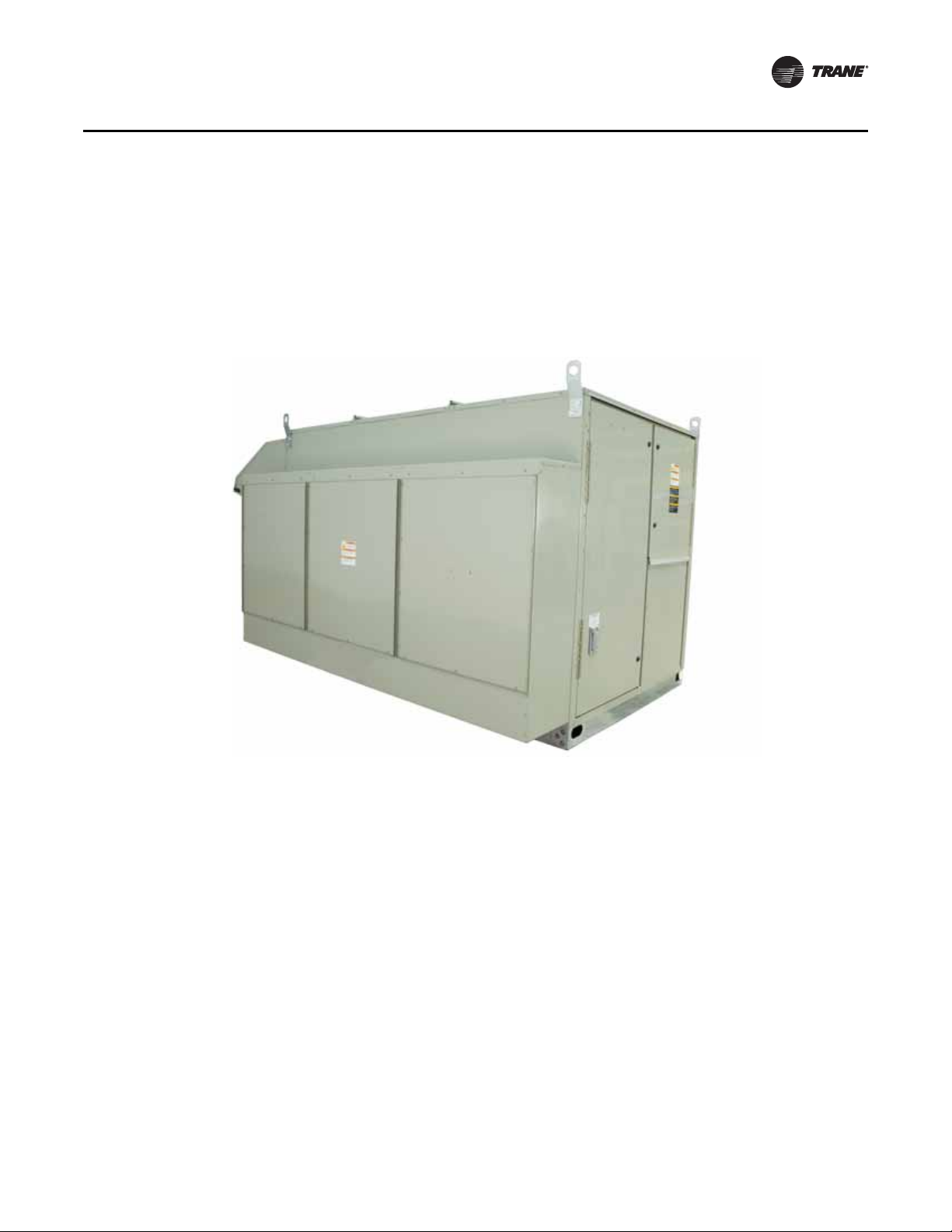
Figure 1. Condenser side view of the Trane Horizon™ Outdoor Air Unit Water Source Heat
Pump
Enhanced Serviceability
• Hinged access doors for ease of maintenance and service
• Easy-open door latches
• Slide out access direct-drive plenum fan
• Optional slide out, self-cleaning total-energy wheel
• Sight glass for each refrigeration circuit
• Optional control display
• High voltage cover
Standard Unit Features
• Multiple cabinet sizes with airflow range from 500 to 13,500 cfm
• Two-inch double-wall, R-13 construction with heavy gauge galvanized metal skin
• Outdoor air inlet hood
• Prepainted exterior finish
• Water-cooled DX refrigeration system
• Completely factory-piped and leak-tested refrigeration system
• Stainless steel drain pans sloped in two planes
• Digital scroll compressors
OAU-PRC003A-EN 11
Page 12

Features and Benefits
• Single-point power connections for units with optional total-energy wheel, powered exhaust,
and electric heat
• Filter rack adjustable for 2-, 4-, or 6-inch filters
• Factory-assembled inlet hood with 2-inch mist eliminators (OAD, OAK, OAN)
• Non-fused disconnect switc h
• Type 439 stainless steel heat exchanger
• Low leak parallel blade outdoor air damper with edge seals
• High-efficiency fan motors
Standard Control Features
• Fully integrated, factory-installed and commissioned microelectronic controls
• Supply airflow proving
• Emergency stop
• Occupied/unoccupied control modes
• High turn-down (up to 20:1) modulating indirect gas-fired heat
• Clogged filter switch
• Low ambient control down to 0°F
Optional Features
• Modulating electric heat
•Hot water coils
• Steam heat (future)
• Low leak parallel blade return air damper with edge seals
• Modulating damper control systems
• Pleated media filters (2-inch MERV-8, 2-inch MERV-13, 4-inch MERV-14, or a combination
2-inch/4-inch filter)
• 24 V electrostatic filters
• 120 V UVC downstream of evaporator coil
• High static fan
• Adjustable powered exhaust
• Exhaust dampers (gravity, barometric relief, and 2-position isolation)
• Fused disconnect switch
• Factory-installed smoke detectors (supply and/or return)
• Integral total-energy wheel
• Protective coatings for the unit and/or coils
• Remote human interface
• Factory or field-wired convenience outlet
• LED service lights
• Direct drive BI airfoil plenum fan
• Factory-installed variable frequency drive (VFD)
• Unit mounted human interface panel
12 OAU-PRC003A-EN
Page 13
Application Considerations
Overview
Outdoor Air Unit Functions
The Horizon™ Outdoor Air Unit (OAU) provides conditioned outdoor air suitable for mec hanical
ventilation or make-up air. The OAU conditions outdoor air as necessary to meet system
performance requirements by ventilation with filtration, cooling, dehumidification, and/or heating.
The OAU may deliver ventilation air in a number of ways. Refer to “System Configurations,” p. 13
and Figure 5, p. 15, Figure 6, p. 15, and Figure 8, p. 16 for more information.
• V entilation with Filtration
• Cooling
• Dehumidification
•Heating
System Configurations
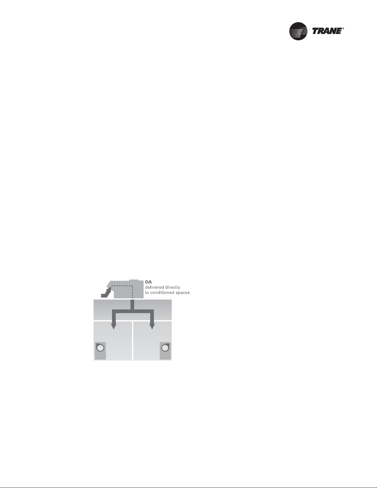
Dedicated outdoor air systems can deliver conditioned outdoor air in one of the following ways:
1. Conditioned outdoor air supplied directly to each occupied space, with the local terminal unit
controlling the space dry-bulb temperature. Refer to Figure 2, p. 13.
2. Conditioned outdoor air supplied directly to local terminal units, or return ducts of lo cal RTUs,
which deliver a mixture of the conditioned outdoor air and (conditioned) recirculated air to the
space. Refer to Figure 3, p. 14.
3. Conditioned outdoor air supplied directly to a single space to control the space temperature
and humidity. F o r example, this application will provide temperature and humidity control of
ventilated spaces, such as commercial kitchens or laboratories.
Figure 2. Direct discharge to conditioned space
OAU-PRC003A-EN 13
Page 14
Application Considerations
Main Condenser
Reheat Coil
Main Evaporator
Expansion Valves
Compressors
Indoor Fan
Figure 3. Indirect discharge to fan-coil units
Horizon OAU Operation
The Horizon™ OAU can use either DX cooling, condenser reheat, electric or gas heat to condition
outdoor air. The unit controls modulate cooling and heating capacity, reducing the supply air
temperature swings associated with staged heating and cooling.
OAU with Reheat
Dehumidification
14 OAU-PRC003A-EN
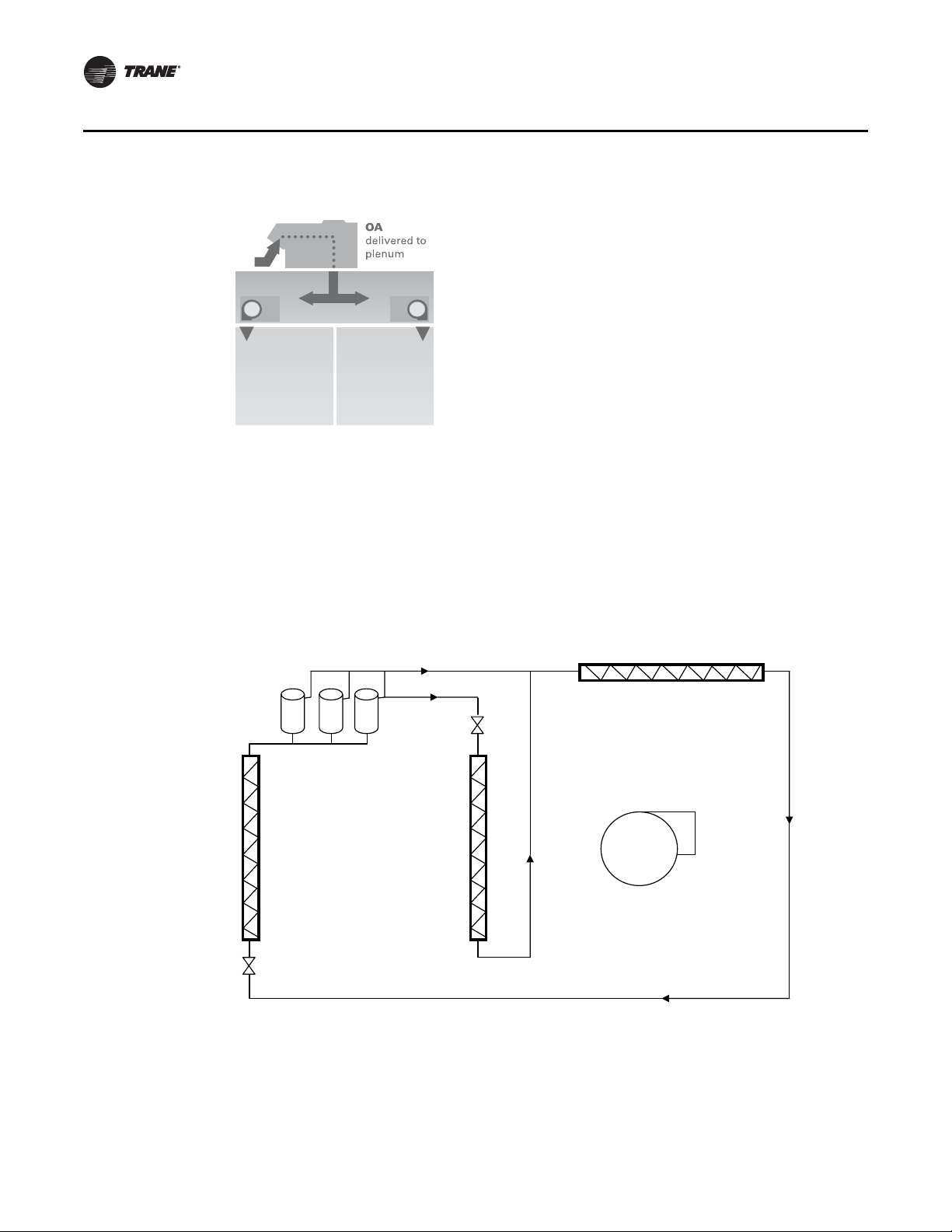
Figure 4, p. 14 shows the OAU system with a DX refrigerant circuit design using reheat.
Figure 4. Refrigeration system diagram with reheat
Consider Figure 5, p. 15. If the outdoor air dew point is above the dehumidification setpoint (or in
the case of zone control, the zone RH is above the RH setpoint), the OAU will:
• cool the outdoor air to remove required moisture and
• reheat to meet the discharge temperature setpoint.
Page 15
Application Considerations
h1
h3
h4
h2
Dry Bulb Temperature
Dewpoint Temperature
Wet Bulb Temperature
t3
t4
heating
t1
t2
cooling
At h1, 100 percent outdoor air enters the O AU . Th e O A U filters, cools, and dehumidifies the air as
it moves through the evaporator coil. Air leaves the evaporator coil saturated at the preset dew
point condition (h3) and is reheated by the reheat coil to the pre-set reheat temperature setpoint
(h4). The reheat coil transfers energy to the airstream. A liquid solenoid valve effectively modulates
the reheat capacity. The outdoor condenser rejects surplus heat. The reheat circuit is first on and
last off, so reheat energy is available at full and part load conditions. Since both the dew point
setpoint and discharge temperature setpoint are fully adjustable, the desired supply air conditions
are maintained at all load conditions.
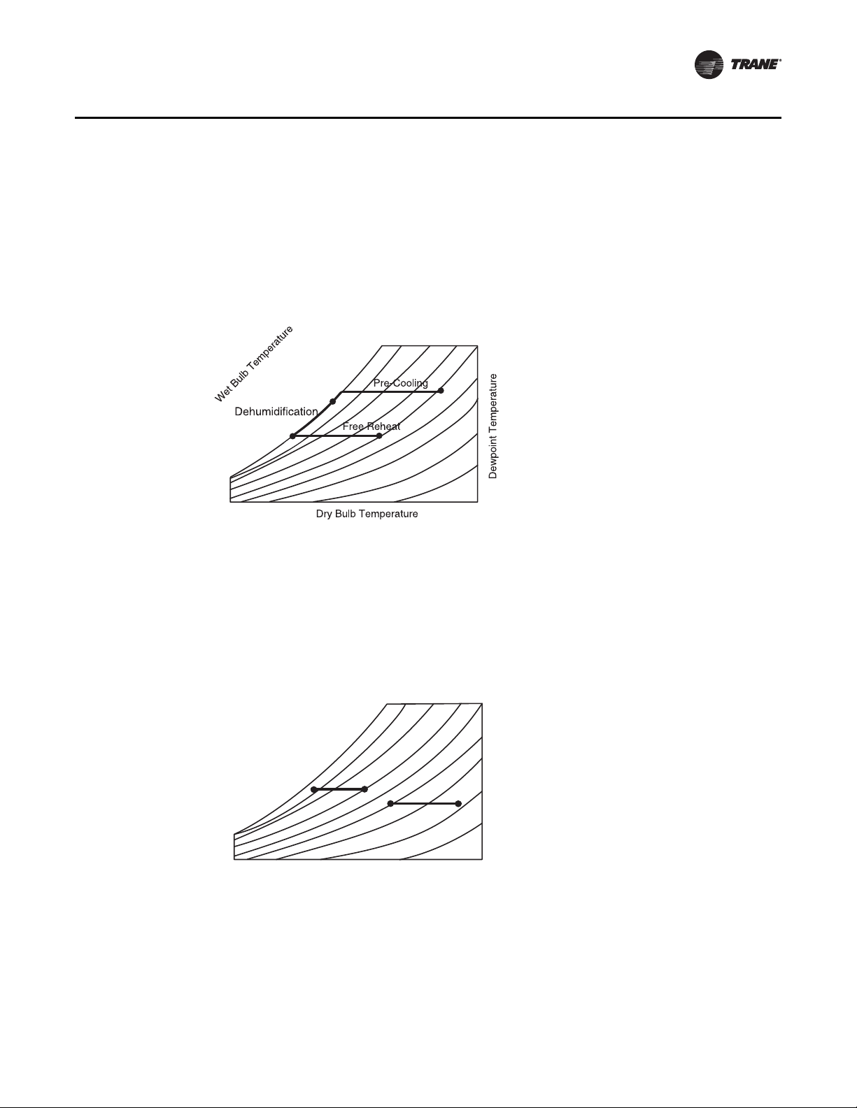
Figure 5. Psychrometric chart with dehumidification and reheat
Cooling or Heating
OAU Outdoor Air Control without Reheat
OAU-PRC003A-EN 15
Consider Figure 6, p. 15. If the outdoor air dew point or zone RH is equal to or below the
dehumidification setpoint, the O AU will heat or cool the outdoor air to separate cooling or heating
setpoints. At t1 or t3, 100 percent outdoor air enters the OA U . The O A U filters, and cools or heats
the air as it is drawn through the evaporator and heating section. The air leaves the OAU at the
cooling or heating discharge setpoint (t2 or t4).
Figure 6. Psychrometric chart with cooling or heating only
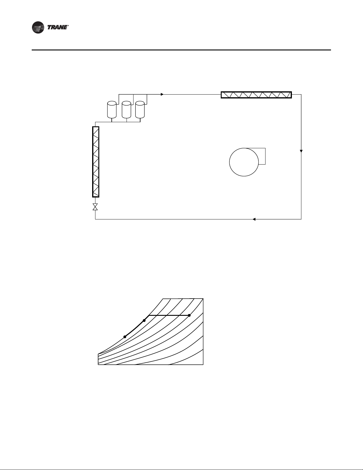
Figure 7, p. 16 shows the Horizon™ OAU DX system, using a refrigerant circuit design without
reheat.
Note: Space control not available without reheat.
Page 16
Application Considerations
Main Condenser
Main Evaporator
Expansion Valves
Compressors
Indoor Fan
Dry Bulb Temperature
Dewpoint Temperature
Wet Bulb Temperature
Dehumidification
h1
h2
h3
Figure 7. Refrigeration system diagram without reheat
Dehumidification
Cooling or Heating
Consider Figure 8, p. 16. If the outdoor air dew point is above the dehumidification setpoint, the
OA U will dehumidify the outdoor air. 100 percent outdoor air enters the OAU (h1). The unit filters,
cools and dehumidifies the air as it is drawn through the evaporator coils. Air leaves the evaporator
coils saturated at a preset dew point setpoint (h3) . Since the dew point setpoint is fully adjustable,
the desired dew point condition is maintained at all load conditions.
Figure 8. Psychrometric chart with dehumidification, no reheat
Consider Figure 9, p. 17. If the outdoor air dew point is below the dehumidification setpoint, the
OAU will heat or cool the outdoor air to separate cooling or heating setpoints. 1 00 percent outdoor
air enters the OAU (t1 or t3). The unit filters and cools or heats the air as it is drawn through the
evaporators and heating section. The air leaves the OAU at the cooling or heating setpoint.
16 OAU-PRC003A-EN
Page 17
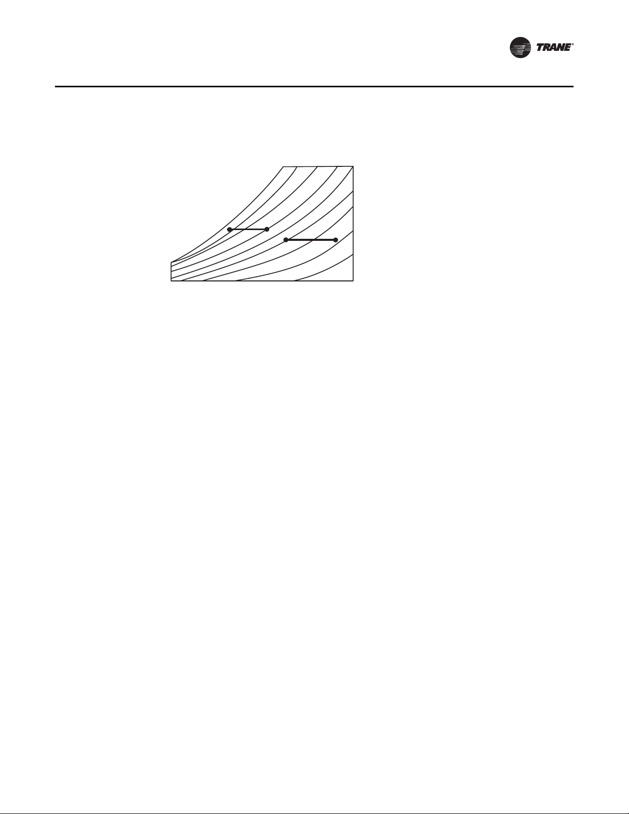
Figure 9. Psychrometric chart with cooling and heating only
Dry Bulb Temperature
Dewpoint Temperature
Wet Bulb Temperature
t3
t4
heating
t1
t2
cooling
Establishing Capacity Requirements
Determining the OAU capacity requirements requires careful thought. Light Commercial
equipment is typically selected based on design sensible conditions. Since latent loads drive the
need for the OAU, base the selection on design latent conditions.
Application Considerations
Cooling & Dehumidification Selection Criteria
Evaporator Design Entering Conditions
Evaporator Design Leaving Conditions
OAU-PRC003A-EN 17
For many climates the peak outdoor air enthalpy occurs at a time when the outdoor dry-bulb
temperature is not the highest. Refer to the ch apter on climatic design information in the A SHRAE
Handbook of Fundamentals. The cooling and dehumidification design condition data is provided
three ways:
1. Design dry-bulb temperature with mean coincident wet bulb temperature
2. Design wet-bulb temperature with mean coincident dry-bulb temperature
3. Design dew point temperature with mean coincident dry-bulb temperature
The design wet-bulb condition typically represents a significantly higher ou tdoor air enthalpy than
the design dry-bulb condition. Use the condition that represents the highest enthalpy as the
entering evaporator selection condition.
Due to the uncertainty of the local terminal unit’s latent capacity at part load, it is usually most
straightforward to size the OAU to handle the entire latent load on the system, both indoor and
outdoor. With this design approach, the terminal units may do some latent cooling
(dehumidification) during periods of higher sensible load. At these times, the space will run slightly
drier than the design RH limit. This is why it makes sense to select the OAU to limit the space RH
to a maximum allowable level for those conditions when the terminal units are pro viding no space
latent cooling, such as 60 percent RH. Using lower humidity limits may result in an unnecessary
increase in system operating energy use.
Use Table 1, p. 18, Table 2, p. 18, and Table 3, p. 19 to identify the appropriate supply air dew point
for specific design conditions. Fo r a more detailed discussion on determining the selection criteria
of a OA U, refer to SYS-APG00 1-EN (Application Guide: Designing Dedicated Outdoor -Air Systems)
or SYS-APM004-EN (Applications Engineering Manual: Dehumidific ati on in HVAC Systems).
Page 18
Application Considerations
Reheat
Table 1. Supply air dew point temperature, 75°F at 60 percent RH space limit
Latent Load
Btu/h per Person
100 54.6 56.6 57.5 58.1 58.4 58.7 58.9 59.0 59.2 59.2 59.3
120 53.3 55.8 57.0 57.6 58.1 58.4 58.6 58.8 58.9 59.1 59.2
140 52.0 55.0 56.4 57.2 57.7 58.1 58.3 58.6 58.7 58.9 59.0
160 50.6 54.2 55.8 56.7 57.3 57.8 58.1 58.3 58.5 58.7 58.8
180 49.2 53.3 55.2 56.3 57.0 57.4 57.8 58.1 58.3 58.5 58.6
200 47.7 52.5 54.6 55.8 56.6 57.1 57.5 57.8 58.1 58.3 58.4
220 46.1 51.6 54.0 55.3 56.2 56.8 57.2 57.6 57.9 58.1 58.3
240 — 50.6 53.3 54.8 55.8 56.5 57.0 57.3 57.6 57.9 58.1
260 — 49.7 52.7 54.3 55.4 56.1 56.7 57.1 57.4 57.7 57.9
280 — 48.7 52.0 53.8 55.0 55.8 56.4 56.8 57.2 57.5 57.7
300 — 47.7 51.3 53.3 54.6 55.5 56.1 56.6 57.0 57.3 57.5
320 — 46.6 50.6 52.8 54.2 55.1 55.8 56.3 56.7 57.1 57.3
340 — 45.5 49.9 52.3 53.8 54.8 55.5 56.1 56.5 56.8 57.1
360 — — 49.251.753.354.455.255.856.356.657.0
380 — — 48.551.252.954.154.955.556.056.456.8
400 — — 47.750.652.553.754.655.355.856.256.6
420 — — 46.950.152.053.354.355.055.656.056.4
440 — — 46.149.551.653.054.054.755.355.856.2
460 — — 45.348.951.152.653.654.455.155.656.0
480 — — — 48.350.652.253.354.254.855.455.8
500 — — — 47.750.251.853.053.954.655.155.6
Note: Minimum dew point selectable is 45°F.
10 15 20 25 30 35 40 45 50 55 60
cfm per person
Table 2. Supply air dew point temperature, 75°F at 55 percent RH space limit
Latent Load
Btu/h per Person
100 51.6 53.8 54.9 55.5 55.9 56.1 56.3 56.5 56.6 56.7 56.8
120 50.2 53.0 54.2 55.0 55.5 55.8 56.1 56.2 56.4 56.5 56.6
140 48.8 52.1 53.6 54.5 55.1 55.5 55.8 56.0 56.2 56.3 56.4
160 47.2 51.2 53.0 54.0 54.6 55.1 55.5 55.7 55.9 56.1 56.2
180 45.6 50.2 52.3 53.5 54.2 54.8 55.2 55.5 55.7 55.9 56.1
200 — 49.3 51.6 53.0 53.8 54.4 54.9 55.2 55.5 55.7 55.9
220 — 48.3 50.9 52.4 53.4 54.1 54.5 54.9 55.2 55.5 55.7
240 — 47.2 50.2 51.9 53.0 53.7 54.2 54.6 55.0 55.2 55.5
260 — 46.2 49.5 51.4 52.5 53.3 53.9 54.4 54.7 55.0 55.3
280 — 45.1 48.8 50.8 52.1 53.0 53.6 54.1 54.5 54.8 55.1
300 — — 48.0 50.2 51.6 52.6 53.3 53.8 54.2 54.6 54.9
320 — — 47.2 49.7 51.2 52.2 53.0 53.5 54.0 54.3 54.6
340 — — 46.4 49.1 50.7 51.8 52.6 53.3 53.7 54.1 54.4
360 — — 45.6 48.5 50.2 51.4 52.3 53.0 53.5 53.9 54.2
380 — — — 47.9 49.8 51.0 52.0 52.7 53.2 53.7 54.0
400 — — — 47.2 49.3 50.6 51.6 52.4 53.0 53.4 53.8
420 — — — 46.6 48.8 50.2 51.3 52.1 52.7 53.2 53.6
440 — — — 46.0 48.3 49.8 50.9 51.8 52.4 53.0 53.4
460 — — — 45.3 47.8 49.4 50.6 51.5 52.2 52.7 53.2
480 — — — — 47.2 49.0 50.2 51.2 51.9 52.5 53.0
500 — — — — 46.7 48.6 49.9 50.9 51.6 52.2 52.7
Note: Minimum dew point selectable is 45°F.
10 15 20 25 30 35 40 45 50 55 60
cfm per person
18 OAU-PRC003A-EN
Page 19

Application Considerations
Table 3. Supply air dew point temperature, 75°F at 50 percent RH space limit
Latent Load
Btu/h per Person
100 48.4 50.8 51.9 52.6 53 53.3 53.6 53.8 53.9 54 54.1
120 46.8 49.8 51.3 52.1 52.6 53 53.3 53.5 53.6 53.8 53.9
140 45.2 48.9 50.6 51.5 52.2 52.6 52.9 53.2 53.4 53.5 53.7
160 — 47.9 49.8 51 51.7 52.2 52.6 52.9 53.1 53.3 53.5
180 — 46.8 49.1 50.4 51.3 51.8 52.3 52.6 52.9 53.1 53.3
200 — 45.7 48.4 49.8 50.8 51.5 51.9 52.3 52.6 52.8 53.0
220 — — 47.6 49.3 50.3 51.1 51.6 52 52.3 52.6 52.8
240 — — 46.8 48.7 49.8 50.7 51.3 51.7 52.1 52.4 52.6
260 — — 46 48.149.450.350.951.451.852.152.4
280 — — 45.2 47.4 48.9 49.8 50.6 51.1 51.5 51.9 52.2
300 — — — 46.848.449.450.250.851.351.651.9
320 — — — 46.2 47.9 49 49.8 50.5 51 51.4 51.7
340 — — — 45.547.348.649.550.250.751.151.5
360 — — — — 46.8 48.2 49.1 49.8 50.4 50.9 51.3
380 — — — — 46.3 47.7 48.7 49.5 50.1 50.6 51
400 — — — — 45.7 47.3 48.4 49.2 49.8 50.4 50.8
420 — — — — 45.2 46.8 48 48.9 49.6 50.1 50.6
440 — — — — — 46.3 47.6 48.5 49.3 49.8 50.3
460 — — — — — 45.9 47.2 48.2 49 49.6 50.1
480 — — — — — 45.4 46.8 47.9 48.7 49.3 49.8
500 — — — — — — 46.4 47.5 48.4 49.1 49.6
Note: Minimum dew point selectable is 45°F.
10 15 20 25 30 35 40 45 50 55 60
The Trane OAU utilizes recovered energy from the cooling process to reheat the air leaving the
evaporator coil as required to meet the discharge air setpoint. The reheat refrigeration circuit is
adequate to deliver enough reheat to supply neutral-temperature air (e.g., 75°F dry-bulb) under
most operating conditions. On very low load days, the reheat circuit may not contain enough
energy to meet the desired reheat setpoint.
cfm per person
Heating
The OA U has electric, heat pump, or g as heat option s. The elec tric he at option is available in 0°F–
80°F temperature rise offerings with SCR modulation. This means that the lowest temperature rise
provided depends only on heater size and unit airflow . Cal cul at e the tem perature rise to confirm
that it provides acceptable control. The electric heat will modulate to maintain heating setpoint.
When using hot water heat, the unit controller will modulate a field-provided coil control valve.
Provide an ethylene glycol and water mixture or other means of freeze protection for the hot water
coil if the OAU will be subject to sub-freezing temperatures.
Capacity Control
The capacity control system on the Horizon™ Outdoor Air Unit is flexible enough to accommodate
a variety of system applications. These applications include:
• treating outdoor air to supply a single space or multiple spaces or
• simultaneously meet building make-up air needs while controlling the temperature and relative
humidity of a single space.
Each of these applications requires careful consideration to achieve the desired results.
Discharge Air Control
For many multiple spac e, dedicated outdoor air systems, the O AU will continuously supply outdoor
air at a dry-bulb setpoint and a dew point that does not exceed its dew point setpoint. Th is control
approach is simple because it allows the OAU to function independent of local terminal unit
operation or actual space conditions. If the unit selection cri teria is determined using the method
suggested in“Establishing Capacity Requirements,” p. 17, the Outdoor Air Unit will limit the space
relative humidity to the target level.
OAU-PRC003A-EN 19
Page 20

Application Considerations
Many dedicated outdoor air systems supply reheated air directly to terminal units or to spaces that
have terminal units performing local sens ible cooling. This results in the local terminal units recooling the previously re-heated outdoor air . Resetting the supply air dry-bulb temperature of the
Outdoor Air Unit offers the opportunity to minimize the amount of time re-cooling occurs. Refer to
“Cooling Setpoint,” p. 20 for more information.
Cooling Setpoint
Because the T rane O AU dehumidifies the outdoor air by cooling it, th is cool outdoor air can reduce
the sensible cooling load on the local terminal unit. At low space sensible loads, the cool outdoor
air may sub-cool the space, causing the local terminal unit to add heat (new energy heat).
Therefore, reset occupied Space Cooling Setpoint (SPCS—Space Control Sequ ence) or Evaporator
Cooling Setpoint (ECS—Outdoor Air Contro l Sequence) of the O A U to minimize space sensible recooling so the terminal unit with the lowest sensible load is almost at zero cooling capacity (within
the limit of the dew point setpoint). To take full advantage of space demand based dry-bulb reset,
you may need to size some of the local terminal units based on neutral outdoor air temperature.
This strategy will more effectively manage occupant comfort during seasonal changeover for twopipe terminal unit systems. Because the OAU is not connected to the chiller or boiler plant,
accomplish this by resetting the Outdoor Air Unit SPCS or ECS to keep the critical zone at zero
heating capacity when the boiler is off and zero cooling capacity when the chiller is off. A Trane
Integrated Comfort™ system can provide this control capability.
Unoccupied Space Humidity Control
The Horizon™ O AU pro vides conditioned outdoor air for the ventilation and/or make-up air needs
of a building during occupied hours. It can also limit building relative humidity during unoccup ied
hours. To do this, provide a return air path to the OAU and place a relative humidity sensor in the
space served by the OAU or in a common relief air path (like a return corridor) if the OAU serves
multiple spaces. The unit will cycle as required to limit the space humidity to the unoccupied
Dewpoint Setpoint (NSDS) setpoint. Reheat and return air damper options are required for this
operation. For dedicated outdoor air systems ducted to terminal units, these units must cycle with
the operation of the Horizon OA U. A Trane Integrated Comfort™ system can provide this control
capability.
Space Control
For single space applications, the Horizon OAU can control space temperature and limit space
relative humidity. To do this, size the airflow to meet whichever is the highest: the space loads and
ventilation and/or make-up air needs of the application. Install a temperature sensor in the space
to provide temperature control and reset the supply air temperature. If reset of the supply air dew
point is desired, install a space relative humidity sensor in the space to provide relative humidity
limit control.
Outdoor Airflow Balancing
Establish final unit airflow through a field air balancing procedure. Change the fan speed through
replacement or fan sheave adjustment (belt drive indoor fan motor) or VFD Setpoint via the UC600
controller (direct drive fan motor).
Air to Air Energy Recovery
Energy recovery can significantly reduce HVAC system first-cost and operating energy costs.
You can use recovered energy for two purposes:
1. to temper or reheat supply air for independent control of sensible and latent capacity, or
2. to precondition outdoor air as it enters the building for ventilation.
The Horizon™ OAU offers refrigerant heat recovery for reheating the supply air. To precondition
20 OAU-PRC003A-EN
Page 21
the outdoor air, use the optional total-energy wheel to recover energy from building exhaust.
Controlling the Total-Energy Wheel
One way to control an energy recovery device is to turn it on and off with the OAU system
exhaust fan. In this case, the total energy wheel enables when the unit is in occupied mode and
the exhaust fan is running. While this control method is certainly simple and effective in some
applications, it may not provide the expected energy saving benefit, particularly when cold air
(vs. neutral air) is supplied to the building.
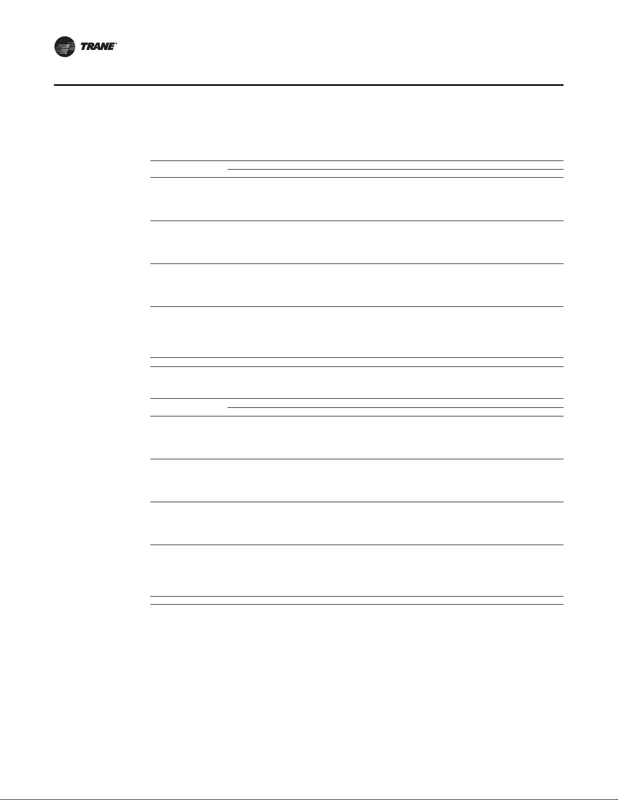
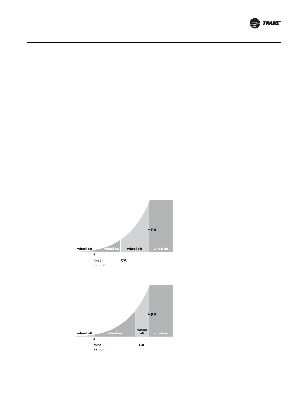
Another more effective approach is to use the outdoor air dry-bulb to determine when to energize or de-energize the energy recovery device. See Figure 11, p. 21 for an example of this simpli-
fied control. In addition to being more effective from a control standpoint, it’s also a very simple
control method because the wheel is enabled when all of the following are true:
• unit is in occupied mode,
• exhaust fan is enabled,
• Unit Main Control Module (MCM) calls for unit to operate in dehumidification, cooling, or
heating modes, and
• outside air temperature is above the frost protection setpoint (default setpoint 12°F).
If using the O AU to deliver cold, dry conditioned air to th e building (ou tdoor air is cooled to a low
dew point but not reheated), use the cooling setpoint control strategy (see “Cooling Setpoint,”
p. 20).
Application Considerations
Figure 10. Dry-bulb control in a cold DB/dry DP application
Figure 11. Dry-bulb control in a neutral DB/dry DP application
OAU-PRC003A-EN 21
Page 22

Application Considerations
PANEL ENCLOSURE
D" NPT FEMALE
CONNECTOR
CLEANOUT PLUG
D = PIPE DIAMETER
H = INTERNAL STATIC PRESSURE (IN W.G.) + 1"
J = H * 0.5
L = H + J + D
NOTES: 1. PITCH DRAIN AT LEAST 1/2" PER 10' HORIZ ONTAL RUN
2. CONDENSATE DRAIN PAN WILL NOT DRAIN PROPERLY IF
P-TRAP IS NOT PRIMED & OF ADEQUATE HEIGHT TO
A
L
L
OW FOR CABINETOPERATING NEGATIVE PRESSURE
Cross Leakage
All energy wheels have some cross leakage. Therefore, do not use energy wheels in applications
involving toxic or hazardous air streams. The percentage of cross leakage depends on the pressure
differentials across the wheel section. With Trane Horizon™ OAU energy wheels, the exhaust air
transfer ratios are typically low (less than 4 percent).
Condensate Drain Configuration
OAU units are selected based on dehumidification capability. As such, condensate can form at a
high rate. Therefore, the OAU drain pan and condensate line are siz ed and designed accordingly.
However, an often-o verlooked element of proper condensate drainage is proper P-T rap and drain
line sizing and installation. An incorrectly-designed and -installed P-Trap can restrict condensate
flow or cause water in the condensate drain pan to “spit” or “geyser” which may cause condensate
overflow. Carefully install and trap the drain pan to ensure adequate condensate removal under all
conditions.
An evaporator condensate drain connection is provided on each unit. For more inform ation, to the
Installation, Operation, and Maintenance for your specific product:
• OAU-SVX004*-EN (Installation, Operation, and Maintenance: Horizon™ Outdoor Air Unit -
Water Sou r ce Heat Pump - Model: OABE, OADE, OAKE, OANE)
A condensate trap must be installed at the unit due to the drain connection being on the “negative
pressure” side of the fan. Install the P-Trap using the guidelines in Figure 12.
Pitch drain lines connected to P-Trap at least 1/2 inch for every 10feet of horizontal run to assure
proper condensate flow. Do not allow the horizontal run to sag causing a possible double-trap
condition which could result in condensate backup due to “air lock”.
Figure 12. Condensate trap installation
22 OAU-PRC003A-EN
Page 23

Acoustical Considerations
Proper unit placement is critical to reducing transmitted sound levels from the OAU to the building.
Therefore, consider acoustic concerns during the design phase and place the unit accordingly. The
most economical means of avoiding an acoustical problem is to place the unit(s) away from
acoustically critical areas. If possible, do not locate units directly above areas such as: offices,
conference rooms, executive office areas, and classrooms. Instead, ideal locations to consider are:
over corridors, utility rooms, toilets, o r oth er areas where hi gh er so un d levels directly below the
unit(s) are acceptable.
Follow these basic guidelines for unit placement to minimize sound transmission through the
building structure.
1. Never cantilever the compressor side of the unit. A structural cross member or full perimeter
roof curb, supported by roof structural members, must support this side of the unit.
2. Locate the unit’s center of gravity close to or over column or main support beam.
3. If the roof structure is very light, replace roof joists by a structural shape in the critical areas
described above.
4. If several units are to be placed on one span, stagger them to reduce deflection over that span.
It is impossible to totally quantify the building structure effect on sound transmissio n because it
is dependent on how the roof and building members respond to the O AU’s sound and vibration.
However, following the guidelines listed above will help reduce sound transmissions.
Application Considerations
Clearance Requirements
Follow the recommended unit clearances to assure adequate serviceability, maximum capacity,
and peak operating efficiency . Reducing unit clearances may result in condenser coil starvation or
warm condenser air recirculation. If the recommended clearances are not possible on a par ticular
job, consider the following:
• Do the clearances available allow for major service work, such as changing compressors or
coils?
• Do the clearances available allow for proper outside air intake, exhaust air removal, and
condenser airflow?
• If screening around the unit is used, is there a possibility of air recirculation from the exhaust
to the outside air intake or from condenser exhaust to condenser intake.
Review any actual clearances that appear inadequate with your local Trane sales engineer.
When two or more units are placed side by side, increase the distance between the units to twice
the recommended single unit clearance. Stagger the units for these two reasons:
1 . T o reduce span deflection if more than one unit is placed on a single span. Reducing deflection
discourages sound transmission.
2. To assure proper exhaust ai r diffusion before contact with the adjacent unit’s outside air intake.
Duct Design
It is important to note that the rated capacities of the OAU can be met only if the unit is properly
installed. A well-designed duct system is essential to meet these capacities.
Satisfactory air distri bution throughout the system requires an unrestricted and uniform airflow
from the OAU discharge duct.
However, when job conditions dictate installation of elbows near the OAU outlet, using guide vanes
may reduce capacity loss and static pressure loss.
OAU-PRC003A-EN 23
Page 24

Application Considerations
Controls Sequence
For sequence of operation, please refer to the Installation, Operation, and Maintenance for your
specific product:
• OAU-SVX004*-EN (Installation, Operation, and Maintenance: Horizon™ Outdoor Air Unit -
Water Sou r ce Heat Pump - Model: OABE, OADE, OAKE, OANE)
24 OAU-PRC003A-EN
Page 25

Selection Procedure
Horizon OAU WSHP Selection Procedure
The Horizon™ Outdoor Air Unit (OAU) is designed to efficiently dehumidify outdoor air. As such,
the selection of an OA U is somewhat more complex than a standard recirculation roof top. T o make
it easier, there is an online selection tool provided. Before launching the program, the following
information about the specific project will be required:
1. Entering Air Temperature (DB/WB)
a. Summer
b. Winter
2. Entering Water Temperature (EWT) Cooling
3. Fluid Flow
4. Fluid Type (Water, Propylene, or Ethylene)
5. Volume Glycol (if Propylene or Ethylene is used)
6. EAT—Heating
7. EWT—H ea ti ng
8. Condenser Material (copper inner tubes are recommended for fresh and cooling tower water
applications while cupro-nickel is recommended for ground and sea water applications)
9. CFM
a. Total CFM
b. Outdoor Air CFM
10. External Static Pressure
11. Altitude
12. Electrical Voltage/Phase/Hertz
13. Heat Type
After initial entry, the tool will search all possible options, and display those which may be
acceptable. If a certain tonnage is not available given the project specifics, there is an option to view
the reason for that unit’ s rejectio n. Of the units available, select the one that is most suited to the
project, based on CFM, motor speed, or leaving air conditions. Leaving air conditions off the coil
as well as unit leaving air temperature are displayed. For distributors, a price is displayed. The unit
selected will be saved as its current configuration. If circumstances c hange af ter the unit is saved,
the program will require a reconfiguration, at which time the price will be adjusted as well.
OAU-PRC003A-EN 25
Page 26

General Data
Table 4. OABE General Data—Cooling 3–5 Ton s H igh Efficiency
3 Tons 4 Tons 5 Tons
OABE036A OABE048A OABE060A
Performance
Gross Cooling Capacity, Btu (kW) 41,800 (12.25) 57,439 (16.83) 70,304 (20.60)
Gross Heating Capacity, Btu (kW)
Nominal cfm (m
3
/h) 500–2000 (849–3398) 500–2000 (849–3398) 500–2000 (849–3398)
Compressor
Number 1 1 / Scroll 1 / Scroll
Type
Fluid/Refrigerant Water Coil
Type Coaxial Coaxial Coaxial
Connection Size/Circuit, in. (mm) 3/4 (19.05) 3/4 (19.05) 1 (25.4)
Pressure Drop/Circuit, ft wc (kPa) 4.3 (12.85) 6.4 (19.13) 4.8 (14.35)
Water Flow/Circuit, gpm (L/s) 9 (0.57) 12 (0.76) 15 (0.95)
Indoor Coil
Type High Performance High Performanc e High Performance
Tube Size—OD, i n. (mm)
Face Area, ft
Rows
FPI
Refrigerant Control
Drain Connection Size, in. (mm)
2
(m2) 4.17 (0.39) 4.17 (0.39) 4.17 (0.39)
Indoor Fan
Type Backward Curved Backward Curved Backward Curved
Number Used
Diameter
Drive Type
Number Motors
Motor HP (kW), Standard–Oversized
Motor RPM
Filters
Type Furnished Varies Varies Varies
Evap Size, in. (Qty) 20 x 24 x 2 (2) 20 x 24 x 2 (2) 20 x 24 x 2 (2)
Type Furnished MERV-8 MERV-8 MERV-8
ERV Size, in. (Qty) 20 x 24 x 2 (4) 20 x 24 x 2 (4) 20 x 24 x 2 (4)
Refrigerant Charge, lb of R-410A
36,779 (10.78) 44,667 (13.09) 63,402 (18.58)
Scroll 1 / Scroll 1 / Scroll
1/2 (12.7) 1/2 (12.7) 1/2 (12.7)
4 4 4
12 12 12
TXV TXV TXV
3/4 (19.05) 3/4 (19.05) 3/4 (19.05)
1 1 1
Varies Varies Varies
Direct Drive Direct Drive Direct Drive
1 1 1
2.68–4.0 (2–3) 2.68–4.0 (2–3) 2.68–4.0 (2–3)
Varies Varies Varies
See Nameplate See Nameplate See Nameplate
26 OAU-PRC003A-EN
Page 27

General Data
OABE Units
Table 5. OABE General Data—Cooling 6–9 Ton s H igh Efficiency
6 Tons 7 Tons 8 Tons 9 Tons
OABE072A OABE084A OABE096A OABE108A
Performance
Gross Cooling Capacity, Btu (kW) 81,059 (23.76) 93,010 (27.26) 105,293 (30.86) 115,859 (33.95)
Gross Heating Capacity, Btu (kW)
Nominal cfm (m
3
/h) 625–3000 (1062–5097) 625–3000 (1062–5097) 625–3000 (1062–5097) 625–3000 (1062–5097)
Compressor
Number 1 1 1 1
Type Scroll Scroll Scroll Scroll
Fluid/Refrigerant Water Coil
Type Coaxial Coaxial Coaxial Coaxial
Connection Size/Circuit, in. (mm)
Pressure Drop/Circuit, ft wc (kPa)
Water Flow/Circuit, gpm (L/s)
Indoor Coil
Type High Performance High Performance High Performance High Performance
Tube Size—OD, i n. (mm)
Face Area, ft
Rows
FPI
Refrigerant Control
Drain Connection Size, in. (mm)
2
(m2) 6.56 (0.61) 6.56 (0.61) 6.56 (0.61) 6.56 (0.61)
Indoor Fan
Type Backward Curved Backward Curved Backward Curved Backward Curved
Number Used
Diameter
Drive Type
Number Motors
Motor HP (kW), Standard–Oversized
Motor RPM
Filters
Type Furnished Varies Varies Varies Varies
Evap Size, in. (Qty) 20 x 24 x 2 (2) 20 x 24 x 2 (2) 20 x 24 x 2 (2) 20 x 24 x 2 (2)
Type Furnished MERV-8 MERV-8 MERV-8 MERV-8
ERV Size, in. (Qty) 20 x 24 x 2 (4) 20 x 24 x 2 (4) 20 x 24 x 2 (4) 20 x 24 x 2 (4)
Refrigerant Charge, lb of R-410A
75,344 (22.08) 85,183 (24.96) 100,455 (29.44) 108,943 (31.93)
1 (25.4) 1 (25.4) 2 (50.8) 2 (50.8)
6.3 (18.83) 8.2 (24.51) 5.9 (17.64) 7.4 (22.12)
18 (1.14) 21 (1.32) 24 (1.51) 27 (1.70)
1/2 (12.7) 1/2 (12.7) 1/2 (12.7) 1/2 (12.7)
4 4 4 4
12 12 12 12
TXV TXV TXV TXV
3/4 (19.05) 3/4 (19.05) 3/4 (19.05) 3/4 (19.05)
1 1 1 1
Varies Varies Varies Varies
Direct Drive Direct Drive Direct Drive Direct Drive
1 1 1 1
2.68-4.0 (2-3) 2.68-4.0 (2-3) 2.68-4.0 (2-3) 2.68-4.0 (2-3)
Varies Varies Varies Varies
See Nameplate See Nameplate See Nameplate See Nameplate
OAU-PRC003A-EN 27
Page 28

General Data
OADE Units
Table 6. OADE Gener a l Data—Cooling 5–8 Tons High Efficiency
5 Tons Downflow 6 Tons Downflow 7 Tons Downflow 8 Tons Downflow
OADE060A OADE072A OADE084 OADE096
Performance
Gross Cooling Capacity, Btu (kW) 71,522 (20.96) 81,032 (23.75) 101,129 (29.64) 110,880 (32.50)
Gross Heating Capacity, Btu (kW) 63,292 (18.55) 74,463 (21.82) 82,750 (24.25) 101,852 (29.85)
Nominal cfm (m
Compressor
Number 1112
Type Scroll Scroll Scroll Scroll
Fluid/Refrigerant Water Coil
Type Coaxial Coaxial Coaxial Coaxial
Connection Size/Circuit, in. (mm) 1 (25.4) 1 (25.4) 1 (25.4) 1/1 (25.4/25.4)
Pressure Drop/Circuit, ft wc (kPa) 4.8 (14.35) 7.9 (23.61) 8.2 (24.51) 6.4/6.4 (19.13/19.13)
Water Flow/Circuit, gpm (L/s) 15 (0.95) 18 (1.14) 21 (1.32) 12/12 (0.76/0.76)
Indoor Coil
Type High Performance High Performance High Performance High Performance
Tube Size—OD, in. (mm) 1/2 (12.7) 1/2 (12.7) 1/2 (12.7) 1/2 (12.7)
Face Area, ft
Rows 4444
FPI 12121212
Refrigerant Control TXV TXV TXV TXV
Drain Connection Size, in. (mm) 3/4 (19.05) 3/4 (19.05) 3/4 (19.05) 3/4 (19.05)
Indoor Fan
Type Backward Inclined Backward Inclined Backward Inclined Backward Inclined
Number Used 1111
Diameter Varies Varies Varies Varies
Drive Type Direct Drive Direct Drive Direct Drive Direct Drive
Number Motors 1111
Motor HP (kW), Standard–Oversized 1.0–3.0 1.0–3.0 1.0–3.0 1.0–5.0
Motor RPM 1750–3500 1750–3500 1750–3500 1750–3500
Motor Frame Size (Standard/Oversized) Varies Varies Varies Varies
Filters
Type Furnished Refer to “OAU Filter
Number/Size Recommended
Refrigerant Charge, lb of R-410A
Downflow See Nameplate See Nameplate See Nameplate See Nameplate
3
/h) 625–1250 (1062–2124) 750–1500 (1274–2548) 875–1750 (1487–2973) 1000–2000 (1699–3398)
2
(m2) 6 (0.56) 6 (0.56) 6 (0.56) 9 (0.84)
Guide” in “Appendix, ”
p. 65
Refer to “OAU Filter
Guide” in “Appendix,”
p. 65
Refer to “OAU Filter
Guide” in “Appendix,”
p. 65
Refer to “OAU Filter
Guide” in “Appendix,”
p. 65
28 OAU-PRC003A-EN
Page 29

General Data
OADE Units
Table 7. OADE General Data—Cooling 10–15 Tons High Efficiency
10 Tons Downflow 12 Tons Downflow 15 Tons Downflow
OADE120A OADE144A
Performance
Gross Cooling Capacity, Btu (kW) 143,044 (41.92) 162,064 (47.50) 202,258 (59.28)
Gross Heating Capacity, Btu (kW) 126,584 (37.10) 148,926 (43.65) 165,500 (48.50)
Nominal cfm (m
3
/h) 1250–2500 (2124–4247) 1500–3000 (2548–5097) 1500–3000 (2548–5097)
Compressor
Number 222
Type Scroll Scroll Scroll
Fluid/Refrigerant Water Coil
Type Coaxial Coaxial Coaxial
Connection Size/Circuit, in. (mm) 1/1 (25.4/25.4) 1/1 (25.4/25.4) 1/1 (25.4/25.4)
Pressure Drop/Circuit, ft wc (kPa) 4.8/4.8 (14.35/14.35) 7.9/7.9 (23.61/23.61) 8.2/8.2 (24.51/24.51)
Water Flow/Circuit, gpm (L/s) 15/15 (0.95/0.95) 18/18 (1.14/1.14) 21/21 (1.32/1.32)
Indoor Coil
Type High Performance High Performance High Performance
Tube Size—OD, in. (mm) 1/2 (12.7) 1/2 (12.7) 1/2 (12.7)
Face Area, ft
Rows 444
FPI 121212
Refrigerant Control TXV TXV
Drain Connection Size, in. (mm) 3/4 (19.05) 3/4 (19.05) 3/4 (19.05)
2
(m2) 9 (0.84) 9 (0.84) 9 (0.84)
Indoor Fan
Type Backward Inclined Backward Inclined Backward Inclined
Number Used 1 1 1
Diameter Varies Varies Varies
Drive Type Direct Drive Direct Drive
Number Motors 1 1
Motor HP (kW), Standard–Oversized 1.0–5.0 1.0–5.0
Motor RPM 1750–3500 1750–3500
Motor Frame Size (Standard/
Oversized)
Varies Varies
Filters
Type Furnished Refer to “OAU Filter
Number/Size Recommended
Guide” in “Appendix,”
p. 65
Refer to “OAU Filter
Guide” in “Appendix,”
p. 65
Refrigerant Charge, lb of R-410A
Downflow See Nameplate See Nameplate See Nameplat e
OADE180A
TXV
Direct Drive
1
1.0–5.0
1750–3500
Varies
Refer to “OAU Filter
Guide” in “Appendix,”
p. 65
OAU-PRC003A-EN 29
Page 30

General Data
OAKE Units
Table 8. OAKE Gener a l Data—Cooling 12–20 Tons High Efficiency
12 Tons Downflow 15 Tons Downflow 17 Tons Downflow 20 Tons Downflow
OAKE144A OAKE180A OAKE210A OAKE240A
Performance
Gross Cooling Capacity, Btu (kW) 164,280 (48.15) 208,912 (61.23) 239,236 (70.11) 279,374 (81.88)
Gross Heating Capacity, Btu (kW) 148,018 (43.38) 190,654 (55.88) 208,973 (61.24) 219,466 (64.32)
Nominal cfm (m
Compressor
Number 2222
Type Scroll Scroll Scroll Scroll
Fluid/Refrigerant Water Coil
Type Coaxial Coaxial Coaxial Coaxial
Connection Size/Circuit, in. (mm) 1/1 (25.4/25.4) 1/1 (25.4/25.4) 2/2 (50.8/50.8) 2/2 (50.8/50.8)
Pressure Drop/Circuit, ft wc (kPa) 7.9/7.9 (23.61/23.61) 8.2/8.2 (24.51/24.51) 7.0/7.0 (20.92/20.92) 9.0/9.0 (26.90/26.90)
Water Flow/Circuit, gpm (L/s) 18/18 (1.14/1.14) 21/21 (1.32/1.32) 26.25/26.25 (1.66/1.66) 30/30 (1.89/1.89)
Indoor Coil
Type High Performance High Performance High Performance High Performance
Tube Size—OD, in. (mm) 1/2 (12.7) 1/2 (12.7) 1/2 (12.7) 1/2 (12.7)
Face Area, ft
Rows 4444
FPI 12 12 12 12
Refrigerant Control TXV TXV TXV TXV
Drain Connection Size, in. (mm) 1 (25.4) 1 (25.4) 1 (25.4) 1 (25.4)
Indoor Fan
Type Backward Inclined Backward Inclined Backward Inclined Backward Inclined
Number Used 1 1 1 1
Diameter Varies Varies Varies Varies
Drive Type Direct Drive Direct Drive Direct Drive Direct Drive
Number Motors 1111
Motor HP (kW), Standard–Oversized 1–5.0 1–5.0 1–7.5 1–7.5
Motor RPM 1750–3500 1750–3500 1750–3500 1750–3500
Motor Frame Size (Standard/Oversized) Varies Varies Varies Varies
Filters
Type Furnished Refer to “OAU Filter
Number/Size Recommended
Refrigerant Charge, lb of R-410A
Downflow See Nameplate See Nameplate See Nameplate See Nameplate
3
/h) 1500–3000 (2548–5097) 1875–3750 (3186–6371) 2125–4250 (3610–7221) 2500–5000 (4247–8495)
2
(m2) 9 (0.84) 10 (0.93) 16 (1.49) 16 (1.49)
Guide” in “Appendix,”
p. 65
Refer to “OAU Filter
Guide” in “Appendix, ”
p. 65
Refer to “OAU Filter
Guide” in “Appendix,”
p. 65
Refer to “OAU Filter
Guide” in “Appendix,”
p. 65
30 OAU-PRC003A-EN
Page 31

General Data
OAKE Units
Table 9. OAKE General Data—Cooling 22–30 Tons Hi gh Efficiency
22 Tons Downflow 25 Tons Downflow 30 Tons Downflow
OAKE264A OAKE300A OAKE360A
Performance
Gross Cooling Capacity, Btu (kW) 314,806 (92.26) 348,788 (102.22) 394,638 (115.66)
Gross Heating Capacity, Btu (kW) 289,850 (84.95) 328,446 (96.26) 368,582 (108.02)
Nominal cfm (m3/h)
2750–5500
(4672–9344)
Compressor
Number 222
Type Scroll Scroll Scroll
Fluid/Refrigerant Water Coil
Type Coaxial Coaxial Coaxial
Connection Size/Circuit, in. (mm) 2/2 (50.8/50.8) 2/2 (50.8/50.8) 2/2 (50.8/50.8)
Pressure Drop/Circuit, ft wc (kPa) 11.7/11.7 (34.97/34.97) 13.2/13.2 (39.46/39.46) 18.6/18.6 (55.60/55.60)
Water Flow/Circuit, gpm (L/s) 33/33 (2.08/20.8) 37.5/37.5 (2.37/2.37) 45/45 (2.84/2.84)
Indoor Coil
Type High Performance High Performance High Performance
Tube Size—OD, in. (mm) 1/2 (12.7) 1/2 (12.7) 1/2 (12.7)
Face Area, ft
Rows 444
FPI 121212
Refrigerant Control TXV TXV TXV
Drain Connection Size, in. (mm) 1 (25.4) 1 (25.4) 1 (25.4)
2
(m2) 16 (1.49) 20 (1.86) 20 (1.86)
Indoor Fan
Type Backward Inclined Backward Inclined Backward Inclined
Number Used 1 1 1
Diameter Varies Varies Varies
Drive Type Direct Drive Direct Drive Direct Drive
Number Motors 111
Motor HP (kW), Standard–Oversized 1–7.5 1.0–15.0 1.0–15.0
Motor RPM 1750–3500 1750–3500 1750–3500
Motor Frame Size (Standard/
Oversized)
Varies Varies Varies
Filters
Type Furnished Refer to “OAU Filter
Number/Size Recommended
Guide” in “Appendix,”
p. 65
Refrigerant Charge, lb of R-410A
Downflow See Nameplate See Nameplate See Nameplate
3125–6250
(5309–10619)
Refer to “OAU Filter
Guide” in “Appendix,”
p. 65
3750–7500
(6371–12742)
Refer to “OAU Filter
Guide” in “Appendix,”
p. 65
OAU-PRC003A-EN 31
Page 32

General Data
OANE Units
Table 10. OANE General Data—Cooling 30–40 Tons High Efficiency
30 Tons Downflow 35 Tons Downflow 40 Tons Downflow
OANE360A OANE420A OANE480A
Performance
Gross Cooling Capacity, Btu (kW) 407,716 (119.49) 481,429 (141.09) 487,406 (142.84)
Gross Heating Capacity, Btu (kW) 371,280 (108.81) 471,287 (138.12) 477,756 (140.02)
Nominal cfm (m3/h)
3750–7500
(6371–12742)
Compressor
Number 233
Type Scroll Scroll Scroll
Fluid/Refrigerant Water Coil
Type Coaxial Coaxial Coaxial
Connection Size/Circuit, in. (mm) 2/2 (50.8/50.8) 2/2.5 (50.8/63.5) 2/2.5 (50.8/63.5)
Pressure Drop/Circuit, ft wc (kPa) 18.6/18.6 (55.60/55.60) 10.4/9.2 (31.09/27.50) 16.0/13.7 (47.83/40.95)
Water Flow/Circuit, gpm (L/s) 45/45 (2.84/2.84) 31/63 (1.96/3.97) 39/78 (2.46/4.92)
Indoor Coil
Type High Performance High Performance High Performance
Tube Size—OD, in. (mm) 1/2 (12.7) 1/2 (12.7) 1/2 (12.7)
Face Area, ft
Rows 444
FPI 121212
Refrigerant Control TXV TXV TXV
Drain Connection Size, in. (mm) 1-1/4 (31.75) 1-1/4 (31.75) 1-1/4 (31.75)
2
(m2) 22 (2.04) 28 (2.60) 28 (2.60)
Indoor Fan
Type Backward Inclined Backward Inclined Backward Inclined
Number Used 1 1 1 or 2
Diameter Varies Varies Varies
Drive Type Direct Drive Direct Drive Direct Drive
Number Motors 1 1 1 or 2
Motor HP (kW), Standard–Oversized 1.5–15 1.5–15 2.0–15
Motor RPM 1750–3500 1750–3500 1750–3500
Motor Frame Size (Standard/
Oversized)
Varies Varies Varies
Filters
Type Furnished Refer to “OAU Filter
Number/Size Recommended
Guide” in “Appendix,”
p. 65
Refrigerant Charge, lb of R-410A
Downflow See Nameplate See Nameplate See Nameplate
4375–8750
(7433–14866)
Refer to “OAU Filter
Guide” in “Appendix,”
p. 65
5000–10000
(8495–16990)
Refer to “OAU Filter
Guide” in “Appendix,”
p. 65
32 OAU-PRC003A-EN
Page 33

General Data
OANE Units
Table 11. OANE General Data—Cooling 45–54 Tons High Efficiency
45 Tons Downflow 50 Tons Downflow 55 Tons Downflow
OANE540A OANE600A OANE648A
Cooling Performance
Gross Cooling Capacity, Btu (kW) 580,516 (170.13) 707,260 (207.28) 762,312 (223.41)
Gross Heating Capacity, Btu (kW) 535,250 (156.87) 696,574 (204.15) 722,794 (226.48)
Nominal cfm (m3/h)
5625–11250
(9557–19114)
Compressor
Number 344
Type Scroll Scroll Scroll
Fluid/Refrigerant Water Coil
Type Coaxial Coaxial Coaxial
Connection Size/Circuit, in. (mm) 2/2.5 (50.8/63.5) 2.5/2.5 (63.5/63.5) 2.5/2.5 (63.5/63.5)
Pressure Drop/Circuit, ft wc (kPa) 14.9/12.4 (44.54/37.06) 12.8/12.8 (38.26/38.26) 12.4/12.4 (37.06/37.06)
Water Flow/Circuit, gpm (L/s) 40/80 (2.52/5.05) 75/75 (4.73/4.73) 80/80 (5.05/5.05)
Indoor Coil
Type High Performance High Performance High Performance
Tube Size—OD, in. (mm) 1/2 (12.7) 1/2 (12.7) 1/2 (12.7)
Face Area, ft
Rows 444
FPI 121212
Refrigerant Control TXV TXV TXV
Drain Connection Size, in. (mm) 1-1/4 (31.75) 1-1/4 (31.75) 1-1/4 (31.75)
2
(m2) 28 (2.60) 28 (2.60) 28 (2.60)
Indoor Fan
Type Backward Inclined Backward Inclined Backward Inclined
Number Used 1 or 2 1 or 2 1 or 2
Diameter
Drive Type Direct Drive Direct Drive Direct Drive
Number Motors 1 or 2 1 or 2 1 or 2
Motor HP (kW), Standard–Oversized 2.0-15 3.0-15 3.0-15
Motor RPM 1750-3500 1750-3500 1750-3500
Motor Frame Size (Standard/
Oversized)
Varies Varies Varies
Filters
Type Furnished Refer to “OAU Filter
Number/Size Recommended
Guide” in “Appendix,”
p. 65
Refrigerant Charge, lb of R-410A
Downflow See Nameplate See Nameplate See Nameplate
6250–12500
(10619–21237)
Refer to “OAU Filter
Guide” in “Appendix,”
p. 65
6750–13500
(11468–22936)
Refer to “OAU Filter
Guide” in “Appendix,”
p. 65
OAU-PRC003A-EN 33
Page 34

Unit Clearances, Curb Dimensions, and Dimensional
7'-0"
9'-6
13
16
"
END TO END
3'-0"
4'-0"
3'-0"
3'-0"
Data
OABE Units
Unit Clearances
Figure 13. Typical installation clearances for OABE unit
6'-0"
34 OAU-PRC003A-EN
Page 35

Unit Clearances, Curb Dimensions, and Dimensional Data
7'-0"
6'-0"
3'-0"
4'-0"
3'-0"
3'-0"
Figure 14. Typical installation clearances for OABE unit with auxiliary cabinet
OABE Units
Note: Certain options require auxiliary cabinet. Refer to project-specific unit submittals.
OAU-PRC003A-EN 35
Page 36

Unit Clearances, Curb Dimensions, and Dimensional Data
3
" 2
8
3
1
2
"
GUTTER B DETAIL
"5 27
8
3
4
42"
14
8
8
3
10 "
"2 48
1
1
11
8
4
"
"2 93
1
1
25 "
8
39
3
2
"
"
3
"
4
13
8
"
5
1
46 "
" 10
3
8
12
7
8
"
GUTTER B
DETAIL A - GUTTER
SCALE 1 : 14
3 3/4" 3 1/2"
93 1/2"
48 1/2"
46 1/8"
12 7/8"
13 5/8"
25 1/8"
42"
14 3/4"
11 1/4"
27 5/8"
10 1/2"
10 1/2" 38 1/2"
38 3/4"
135 3/4"
DETAIL B - PIPE CHASE GUTTER
SCALE 1 : 12
2 3/8"
3 1/2"
OABE Units
Curb Dimensions
Figure 15. Unit curb data for OABE 3–9 tons
Figure 16. Unit curb data for OABE 3–9 tons with auxiliary cabinet
Note: Certain options require auxiliary cabinet. Refer to project-specific unit submittals.
36 OAU-PRC003A-EN
Page 37

Dimensional Data
5,*+76,'(9,(:
(/(&75,&
',6&211(&7
)52179,(:
7239,(:
5,*+76,'(9,(:
(/(&75,&
',6&211(&7
)52179,(:
7239,(:
Unit Clearances, Curb Dimensions, and Dimensional Data
OABE Units
Figure 17. Unit dimensional data for OABE 3–9 tons (in.)
Figure 18. Unit dime nsional data for OABE 3–9 tons with auxiliary cabinet (in.)
Note: Certain options require auxiliary cabinet. Refer to project-specific unit submittals.
OAU-PRC003A-EN 37
Page 38

Unit Clearances, Curb Dimensions, and Dimensional Data
INDUCER MOTOR
INLET PRESSURE TAP
IGNITION
ON/OFF GAS VALVE
ON/OFF GAS VALVE
MANIFOLD GAS
INLET PRESSURE =
7" W.C./14" W.C.
AIR-PROVING
PRESSURE TAP
SWITCH
MINIMUM/MAXIMUM
PRESSURE TAP
MANIFOLD GAS
ROLLOUT SWITCH
CONTROLLERS
MINIMUM/MAXIMUM
INLET PRESSURE =
7" W.C./14" W.C.
CONDENSATE DRAIN
(TYP. 2)
INDUCER BLOWER
MODULATING VALVE
FLAME
SENSOR
HIGH LIMIT
SWITCH
ROLLOUT
SWITCH
MODULATING
GAS VALVE
MAIN POWER
ENTRANCE FOR UNIT
OABE Units
Figure 19. OABE indirect gas-fired furn ace heater and power
38 OAU-PRC003A-EN
Page 39

Unit Clearances, Curb Dimensions, and Dimensional Data
CLEARANCE 36"
CLEARANCE 48"
CLEARANCE 48"
OF UNIT 72"
CLEARANCE FROM TOP
CLEARANCE 36"
4'-0"
3'-0"
4'-0"
3'-0"
OADE Units
Unit Clearances
Figure 20. Typical installation clearances for OADE unit
OAU-PRC003A-EN 39
Page 40

Unit Clearances, Curb Dimensions, and Dimensional Data
7'-0"
6'-0"
53"
4'-0"
3'-0"
36"
OADE Units
Figure 21. Typical installation clearances for OADE unit with auxiliary cabinet
Note: Certain options require auxiliary cabinet. Refer to project-specific unit submittals.
40 OAU-PRC003A-EN
Page 41

Curb Dimensions
" 2
7
8
6"
GUTTER B DETAIL
SUPPLY
RETURN
GUTTER B
8
"
"
8"
28 3/4"
17"
19"
10 1/2"
49"
45 1/2"
4
83
1
"4 29
3
"1 24
12
1
2
2 7/8"
" 2
7
8
6"
SUPPLY
3
29
4
"
"
40"
8
127
3
"2 36
1
"8 4
1
"
8"
28 3/4"
17"
19"
10 1/2"
49"
45 1/2"
4
83
1
8
"
1
" 24
12
1
2
2 7/8"
GUTTER B
GUTTER A
RETURN
GUTTER B DETAIL
GUTTER A DETAIL
4
1
8
"
5
1
2
"
Unit Clearances, Curb Dimensions, and Dimensional Data
OADE Units
Figure 22. Unit curb data for OADE 5–12 tons
Figure 23. Unit curb data for OADE 5–12 tons with auxiliary cabinet
Note: Certain options require auxiliary cabinet. Refer to project-specific unit submittals.
OAU-PRC003A-EN 41
Page 42

Unit Clearances, Curb Dimensions, and Dimensional Data
46.91
53.00
65.11
87.18
29.63
59.30
87.18
53.00
65.11
46.91
59.30
44.16
35.32
131.33
OADE Units
Dimensional Data
Figure 24. Unit dimensional data for OADE 5–12 tons (in.)
Figure 25. Unit dimensional data for OADE 5–12 tons with auxiliary cabinet (in.)
Note: Certain options require auxiliary cabinet. Refer to project-specific unit submittals.
42 OAU-PRC003A-EN
Page 43

Unit Clearances, Curb Dimensions, and Dimensional Data
INDUCER MOTOR
INLET PRESSURE TAP
IGNITION
ON/OFF GAS VALVE
ON/OFF GAS VALVE
MANIFOLD GAS
INLET PRESSURE =
7" W.C./14" W.C.
AIR-PROVING
PRESSURE TAP
SWITCH
MINIMUM/MAXIMUM
PRESSURE TAP
MANIFOLD GAS
ROLLOUT SWITCH
CONTROLLERS
MINIMUM/MAXIMUM
INLET PRESSURE =
7" W.C./14" W.C.
CONDENSATE DRAIN
(TYP. 2)
INDUCER BLOWER
MODULATING VALVE
FLAME
SENSOR
HIGH LIMIT
SWITCH
ROLLOUT
SWITCH
MODULATING
GAS VALVE
MAIN POWER
ENTRANCE FOR UNIT
Figure 26. OADE indirect gas-fired furnace heater and power
OADE Units
OAU-PRC003A-EN 43
Page 44

Unit Clearances, Curb Dimensions, and Dimensional Data
CLEARANCE 36"
CLEARANCE 48"
CLEARANCE 36"
CLEARANCE FROM TOP
OF UNIT 72"
CLEARANCE 48"
4'-0"
3'-0"
3'-0"
4'-0"
OAKE Units
Unit Clearances
Figure 27. Typical installation clearances for OAKE unit
44 OAU-PRC003A-EN
Page 45

Unit Clearances, Curb Dimensions, and Dimensional Data
CLEARANCE 48"
CLEARANCE 48"
OF UNIT 72"
CLEARANCE FROM TOP
CLEARANCE 36"
CLEARANCE 48"
3'-0"
4'-0"
4'-0"
4'-0"
Figure 28. Typical installation clearances for OAKE unit with auxiliary cabinet
OAKE Units
Note: Certain options require auxiliary cabinet. Refer to project-specific unit submittals.
OAU-PRC003A-EN 45
Page 46

Unit Clearances, Curb Dimensions, and Dimensional Data
7'-0"
6'-0"
6'-0"
7'-0"
OAKE Units
Figure 29. Typical installation clearances for OAKE unit
Figure 30. Typical installation clearances for OAKE unit with auxiliary cabinet
Note: Certain options require auxiliary cabinet. Refer to project-specific unit submittals.
46 OAU-PRC003A-EN
Page 47

Curb Dimensions
S
U
PPL
Y
R
E
T
U
R
N
GUTTER
16 "
102"
30"
29"
4
1
"
56"
4
23
1
3
" 47
4
"4 1
3
TYP.
1"
"2 98
1
2
1
52 "
"4 31
3
"2 22
1
"
1
2
2
22
1
2
"
1
1
2
"
GUTTER DETAIL
2
1
2"
6
1
2
"
GUTTER A DETAIL
8
1
4"
6
1
2
"
S
U
P
P
L
Y
GUTTER A
R
E
T
U
R
N
GUTTER B
2
22
1
2
"
23 "
102"
8
164
1
"8 98
5
"
56"
2
52
1
"4 1
3
"
30"
29"
4
16
1
2
1
54
58"
"
"
1
4
1
2
" 22
"4 31
3
8
1
4"
1"
TYP.
"
1
2
47
3
4
"
GUTTER B DETAIL
2
1
2"
6
1
2
"
Unit Clearances, Curb Dimensions, and Dimensional Data
OAKE Units
Figure 31. Unit curb data for OAKE 12–30 tons (in.)
Figure 32. Unit curb data for OAKE 12–30 to ns with auxiliary cabinet (in.)
Note: Certain options require auxiliary cabinet. Refer to project-specific unit submittals.
OAU-PRC003A-EN 47
Page 48

Unit Clearances, Curb Dimensions, and Dimensional Data
106.45
106.00
135.52
86.05
80.57
OF AIR INLET
43.02
BASE TO BOTTOM
60.00
106.00
86.05
80.57
60.00
62.11
200.99
43.02
BASE TO BOTTOM
OF AIR INLET
106.10
62.51
OAKE Units
Dimensional Data
Figure 33. Unit dimensional data for OAKE 12–30 tons
Figure 34. Unit dimensional data for OAKE 12–30 tons with auxiliary cabinet
Note: Certain options require auxiliary cabinet. Refer to project-specific unit submittals.
48 OAU-PRC003A-EN
Page 49

Figure 35. OAKE furnace heater and power
INDUCER MOTOR
INLET PRESSURE TAP
IGNITION
ON/OFF GAS VALVE
ON/OFF GAS VALVE
MANIFOLD GAS
INLET PRESSURE =
7" W.C./14" W.C.
AIR-PROVING
PRESSURE TAP
SWITCH
MINIMUM/MAXIMUM
PRESSURE TAP
MANIFOLD GAS
ROLLOUT SWITCH
CONTROLLERS
MINIMUM/MAXIMUM
INLET PRESSURE =
7" W.C./14" W.C.
CONDENSATE DRAIN
(TYP. 2)
INDUCER BLOWER
MODULATING VALVE
FLAME
SENSOR
HIGH LIMIT
SWITCH
ROLLOUT
SWITCH
MODULATING
GAS VALVE
MAIN POWER
ENTRANCE FOR UNIT
Unit Clearances, Curb Dimensions, and Dimensional Data
OAKE Units
OAU-PRC003A-EN 49
Page 50

Unit Clearances, Curb Dimensions, and Dimensional Data
CLEARANCE 55"
CLEARANCE 72"
CLEARANCE 36"
CLEARANCE 50"
CLEARANCE 48"
4'-0"
4'-7"
3'-0"
4'-2"
OANE Units
Unit Clearances
Figure 36. Typical installation clearances for OANE unit
50 OAU-PRC003A-EN
Page 51

Unit Clearances, Curb Dimensions, and Dimensional Data
CLEARANCE 36"
CLEARANCE 48"
CLEARANCE 50"
CLEARANCE 55"
CLEARANCE 72"
4'-7"
3'-0"
4'-2"
4'-0"
Figure 37. Typical installation clearances for OANE unit with auxiliary cabinet
OANE Units
Note: Certain options require auxiliary cabinet. Refer to project-specific unit submittals.
OAU-PRC003A-EN 51
Page 52

Unit Clearances, Curb Dimensions, and Dimensional Data
8'-0"
8'-0"
8'-0"
8'-0"
OANE Units
Figure 38. Typical installation clearances for OANE unit
Figure 39. Typical installation clearances for OANE unit with auxiliary cabinet
Note: Certain options require auxiliary cabinet. Refer to project-specific unit submittals.
52 OAU-PRC003A-EN
Page 53

Curb Dimensions
GUTTER DETAIL
"2 2
1
6
1
2
"
S
U
P
P
L
Y
R
E
T
U
R
N
GUTTER
"
2
22
"
1
1
2
2
"
22
66"
1
"
2
63"
1
2
59
140"
"
4
1
3
33"
8
517"
4
221"
2
1361"
TYP.
1"
8
1
293"
2
51 "
1
1
2
"
R
E
T
U
R
N
GUTTER A
S
U
P
P
L
Y
GUTTER B
51 "
63"
2
1
"2 59
1
"
140"
33"
4
1
3
"8 51
7
"4 22
1
"2 136
1
"8 4
1
"8 54
3
"
202"
8
57
7
TYP.
1"
2
"
8
3
29 "
"2 22
1
"
1
2
22
2
1
66"
GUTTER B DETAIL
1
" 2
2
6
1
2
"
GUTTER A DETAIL
1
" 4
8
6
1
2
"
Unit Clearances, Curb Dimensions, and Dimensional Data
OANE Units
Figure 40. Unit curb data for OANE 30–54 tons
Figure 41. Unit curb data for OANE 30–54 tons with auxiliary cabinet
OAU-PRC003A-EN 53
Note: Certain options require auxiliary cabinet. Refer to project-specific unit submittals.
Page 54

Unit Clearances, Curb Dimensions, and Dimensional Data
92.07
144.45
186.14
144.00
93.04
67.00
48.52
BASE TO BOTTOM
OF AIR INLET
OF AIR INLET
248.16
144.00
93.04
67.00
92.07
62.07
48.52
BASE TO BOTTOM
206.55
OANE Units
Dimensional Data
Figure 42. Unit dimensional data for OANE 30–54 tons
Figure 43. Unit dimensional data for OANE 30–54 tons with auxiliary cabinet
Note: Certain options require auxiliary cabinet. Refer to project-specific unit submittals.
54 OAU-PRC003A-EN
Page 55

INDUCER MOTOR
INLET PRESSURE TAP
IGNITION
ON/OFF GAS VALVE
ON/OFF GAS VALVE
MANIFOLD GAS
INLET PRESSURE =
7" W.C./14" W.C.
AIR-PROVING
PRESSURE TAP
SWITCH
MINIMUM/MAXIMUM
PRESSURE TAP
MANIFOLD GAS
ROLLOUT SWITCH
CONTROLLERS
MINIMUM/MAXIMUM
INLET PRESSURE =
7" W.C./14" W.C.
CONDENSATE DRAIN
(TYP. 2)
INDUCER BLOWER
MODULATING VALVE
FLAME
SENSOR
HIGH LIMIT
SWITCH
ROLLOUT
SWITCH
MODULATING
GAS VALVE
MAIN POWER
ENTRANCE FOR UNIT
Figure 44. OANE furnace heater and power
Unit Clearances, Curb Dimensions, and Dimensional Data
OANE Units
OAU-PRC003A-EN 55
Page 56

Unit Weight
Unit Weight
Table 12. Typical unit weights—units without auxiliary cabinet
Model Number
OABE036* 1172 1356 1420 1604
OABE048* 1189 1373 1437 1621
OABE060* 1189 1373 1437 1621
OABE072* 1237 1421 1485 1669
OABE084* 1237 1421 1485 1669
OABE096* 1269 1453 1517 1701
OABE108* 1313 1497 1561 1745
OADE060* 1614 2078 1701 2165
OADE072* 1639 2158 1726 2245
OADE084* 1639 2158 1761 2280
OADE096* 1669 2364 1827 2522
OADE120* 1669 2364 1857 2552
OADE144* 1718 2413 1929 2624
OADE180* 1416 2249 1707 2540
OAKE144* 2685 3350 2895 3560
OAKE180* 2521 3186 2812 3477
OAKE210* 2803 3620 3146 3963
OAKE240* 2831 3648 3223 4040
OAKE264* 2831 3648 3223 4040
OAKE300* 2835 3695 3317 4177
OAKE360* 2909 3769 3391 4251
OANE360* 4631 5614 5276 6259
OANE420* 4946 5929 5592 6575
OANE480* 5039 6051 5714 6726
OANE540* 5106 6063 5726 6683
OANE600* 5270 6352 6043 7125
OANE648* 5282 6364 6055 7137
Note: Minimum and maximum weights vary widely due to the highly configurable nature of the
Operating Weight (lb) Shipping Weight (lb)
Min Max Min Max
product.
56 OAU-PRC003A-EN
Page 57

Table 13. Typical unit weights—units with auxiliary cabinet
Operating Weight (lb) Shipping Weight (lb)
Model Number
OABE036* 1657 1841 1905 2089
OABE048* 1674 1858 1922 2106
OABE060* 1674 1858 1922 2106
OABE072* 1722 1906 1970 2154
OABE084* 1722 1906 1970 2154
OABE096* 1754 1938 2002 2186
OABE108* 1798 1982 2046 2230
OADE060* 2601 3065 2688 3152
OADE072* 2571 3090 2658 3177
OADE084* 2603 3122 2725 3244
OADE096* 2695 3390 2853 3548
OADE120* 2695 3390 2883 3578
OADE144* 2744 3439 2955 3650
OADE180* 2442 3275 2733 3566
OAKE144* 4068 4733 4278 4943
OAKE180* 3947 4612 4238 4903
OAKE210* 4487 5304 4830 5647
OAKE240* 4515 5332 4907 5724
OAKE264* 4515 5332 4907 5724
OAKE300* 4499 5359 4981 5841
OAKE360* 4507 5367 4989 5849
OANE360* 6607 7590 7252 8235
OANE420* 6922 7905 7568 8551
OANE480* 7015 8027 7690 8702
OANE540* 7082 8039 7702 8659
OANE600* 7227 8309 8000 9082
OANE648* 7239 8321 8012 9094
Note: Minimum and maximum weights vary widely due to the highly configurable nature of the
product.
Min Max Min Max
Unit Weight
Rigging
For rigging instructions, please refer to the Installation, Operation, and Maintenance for your
specific product:
• OAU-SVX004*-EN (Installation, Operation, and Maintenance: Horizon™ Outdoor Air Unit -
Water Sou r ce Heat Pump - Model: OABE, OADE, OAKE, OANE)
OAU-PRC003A-EN 57
Page 58

Mechanical Specifications
Horizon Outdoor Air Mechanical Specifications
General
The units shall be down disch arg e ai rflow (OAD, OAK, or OAN) or convertible (OAB) between
down/horizontal for both supply and return openings. Cooling performance shall be rated in
accordance with ETL testing procedures. All units shall be factory assembled, internally wired, ful ly
charged with R-410A, and 100 percent run tested to check cooling operation, fan and blower
rotation, and control sequence before leavin g the factory. Wiring internal to the unit shall be
colored and numbered for simplified identification. Un its shall be ETL listed and labeled, classified
in accordance to UL 1995/CAN/CSA No. 236-M40 for Central Cooling Air Conditioners. Canadian
units shall be CSA Certified.
Casing
Unit casing shall be constructed of zinc-coated, heavy gauge, galvanized steel. Exterior surfaces
shall be cleaned, phosphatized, and fini shed with a weather-resistant baked enamel finish. Unit’s
surface shall be tested 672 hours in a salt spray test in compliance with AS TM B1 17. Unit shall have
a 2-inch thick Antimicrobial Insulation with an R-value of 13. All insulation edges shall be either
captured or sealed. The unit’s base pan shall have no penetrations within the perimeter of the curb
other than the raised downflow supply/return op en in gs to pr ovide an added water integrity
precaution, if the condensate drain backs up. The top cover shall be one piece construction or,
where seams exist, it shall be double-hemmed and gasket-sealed. The ribbed top adds extra
strength and enhances water removal from unit top.
Drain Pan
The drain pan is a single-walled assembly made of Type 304 stainless steel. It is sloped in two
planes and is fully drainable. The coils are mounted abo ve the drain pan to allow easy inspection
and cleaning of the drain pan.
Refrigeration and Dehumidification Systems
Compressors
All units shall have direct-drive, hermetic, scroll type compressors with centrifugal type oil pumps.
Motor shall be suction gas-cooled and shall have a voltage utilization range of plus or minus
10 percent of unit nameplate voltage. Internal overloads shall be provided with the scroll
compressors. Each compressor has a crankcase heater to minimize the amount of liquid refrigerant
present in the oil sump during off cycles.
58 OAU-PRC003A-EN
Page 59

Mechanical Specifications
Evaporator Coils
Refer to Figure 45. Internally finned copper tubes mechanically bonded to a configured aluminum
plate fin shall be standard. Coils shall be leak tested at the factory to ensure the pressure integrity.
The evaporator coil and condenser coil shall be leak tested to 500 psig and pressure tested to
500 psig. Evaporator coil will have four interlaced rows for superior sensible and latent cooling.
Figure 45. Evaporator and reheat coil
Condenser—Water Cooled (Copper/Steel or 90/10 CuNi Condenser Tubes)
The condenser coils utilize a coaxial “tube in tube” design. Water flows through the inner tube
while refrigerant flows in the annulus between the inner and outer tubes. The coils have a
convoluted multi-lead inner tube which has increased heat transfer surface area per unit length yet
still permits full flow of both water and refrigerant around its entire periphery for improved
performance. Turbulence imparted by the convolutions to both the water and refrigerant flows
further enhances the thermal performance, while inhibiting the accumulation of deposits on the
surfaces.
Digital Scroll Compressors
Units with digital scroll type compressors shall have direct-drive, hermetic compressors with
centrifugal type oil pumps. Motor shall be suction gas-cooled and shall have a voltage utilization
range of plus or minus 10 percent of unit nameplate voltage. Internal overloads shall be provided
with the scroll compressors. Crankcase heaters shall be included. Compressor shall be able to fully
modulate from 20 percent to 100 percent.
OAU-PRC003A-EN 59
Page 60

Mechanical Specifications
Total Energy Wheel (Composite)
The rotating wheel heat exchanger is composed of a rotating cylinder in an insulated cassette frame
complete with seals, drive motor, and drive belt. The total-energy recovery wheel is coated with
silica gel desiccant permanently bonded by a patented and proprietary process without the use of
binders or adhesives, which may degrade desiccant performance. The substrate is a lightweight
polymer and will not degrade nor require additional coatings for application in mari ne or coastal
environments. Coated segments are washable with detergent or alkaline coil cleaner and water.
Desiccant will not dissolve nor deliquesce in the presence of water or high humidity . As the wheel
rotates between the ventilation and exhaust air streams it picks up sensible and latent heat energy
and releases it into the colder air stream. The driving force behind the exchange is the difference
in temperatures between the opposing air streams which is also called the thermal gradient.
Bypass dampers will be provided on both the outside and exhaust air paths.
Total Energy Wheel (Aluminum)
The rotor media shall be lightweight and be made of aluminum. The rotor media shall be coated
to prohibit corrosion; etched or oxidized surfaces are not acceptable. All surfaces must be coated
with a non-migrating adsorbent layer of desiccant prior to being formed into the honeycomb media
structure to insure that all surfaces are coated and that adequate latent capacity is provided. The
desiccant must be designed for the adsorption of water vapor . The media shall be cleanable with
low temperature steam, hot water or light detergent without degrading the latent recovery . Bypass
dampers will be provided on both the outside and exhaust air paths.
Figure 46. Total-energy wheel module
60 OAU-PRC003A-EN
Page 61

Mechanical Specifications
Supply and Exhaust Fan and Motors (OAD, OAK, and OAN)
Fan motor shall be direct drive type with factory installed V ariable Frequency Drive. All motors shall
be thermally protected. All indoor fan motors meet the U.S. Energy Policy Act of 2005 (EPACT).
Refer to Figure 47.
Figure 47. Indoor fan and motor
Supply and Exhaust Fan and Motors (OAB)
Fan shall be a high efficiency bac kward curved impeller . The motor shall be an electronic commuted
motor (ECM) with integrated power electronics.
Dampers— Low Leak
The outside air damper has a unit-controlled actuator with parallel-blades. The blade const ruction
is a 14-gage g alvan ized steel, roll-formed airfoil-type.
Electrical and Controls
Controls
Unit is completely factory-wired with necessary controls and contactor pressure lugs for power
wiring. Units will provide an external location for mounting fused disconnect device. Microprocessor controls are provided for all 24-volt con trol funct ion s. Th e resident con tro l algorithms
will make all heating, cooling and/or ventilating decisions in response to electronic signals from
sensors measuring outdoor temperature and humidity. The control algorithm maintains accurate
temperature control, minimizes drift from set point, and provides better building comfort. A
centralized micro-processor (RTRM) will provide anti-short cycle timing for a higher level of
machine protection. T erminals are pro vided for a field installed dry contact or switc h closure to put
the unit in the Occupied or Unoccupied modes.
OAU-PRC003A-EN 61
Page 62

Mechanical Specifications
Options
Electric Heating Option
Primary heat is supplied using Electr ic Resistance heaters. Heaters shall mee t the requirements of
the National Electrical Code and shall be listed by Underwriters Laboratories for zero clearance to
combustible surfaces and for use with heat pumps and air conditioning equipment. Heati ng
elements shall be open coil, 80 percent nickel, 20 percent chromium, Grade A resistance wire.
T ype C alloys containing iron or other alloys are not acceptable. Coils shall be machine crimped into
stainless steel terminals extending at least 1 inch into the air stream and all terminal hardware shall
be stainless steel. Coils shall be supported by ceramic bushings staked into supporting brackets.
Heater frames and terminal boxes shall be corrosion resistant steel. Unless otherwise indicated,
the terminal box shall be NEMA 1 construction and shall be provided with a hinged, latching cover .
Heaters shall be furnished with a disc type, automatic reset thermal cutout for primary over
temperature protection. All heaters shall also be furnished with disc type, load-carrying manual
reset thermal cutouts, factory wired in series with heater stages for secondary protection. Heat
limiters or other fusible over temperature devices are not acceptable. Control will be SCR type. Unit
shall be suitable for use with Electric Resistance Heat. Refer to Figure 48.
Figure 48. ER Heater
Gas-Fired Heating Option
Primary heat is supplied using indirect fired gas heatin g. Th e heatin g sect ion shal l have a
progressive tubular heat exchanger design using stainless steel burners and T ype409 stainless
steel tubes. An induced draft combustion blower shall be used to pull the combustion products
through the firing tubes. The heater shall use a direct spark ignition (DS) system. On initial call for
heat, the combustion blower shall purge the heat exc h anger for 20 seconds before ignition. Af ter
three unsuccessful ignition attempts, the entire heating system shall be locked out until manually
reset at the thermostat/zone sensor . Units shall be comply with the California requirement for low
emissions. Unit shall be suitable for use with Natural Gas.
NO
x
62 OAU-PRC003A-EN
Page 63

Mechanical Specifications
Hydronic Heat Option
A factory installed one, two, or three row hydronic heating coil will be provided downstream of the
fan. The unit controller provides a modulating output to control a field-installed wa ter valve and
accepts a low temperature limit input signal. Openings in the unit side panels for piping must also
be field constructed.
Condenser Hot Gas Reheat
This option shall consist of a modulating hot-gas reheat coil located on the leaving air side of the
evaporator coil pre-piped and circuited with a low pressure switch. For detailed unit control and
operational modes, please refer to the Sequence of Operations in the Installation, Operat ion, and
Maintenance for your specific product:
• OAU-SVX004*-EN (Installation, Operation, and Maintenance: Horizon™ Outdoor Air Unit -
Water Sou r ce Heat Pump - Model: OABE, OADE, OAKE, OANE)
Return Air
Air returns vertically through the unit base. Dampers are low-leak. Each damper has a unitcontrolled actuator. Inputs are provided for unoccupied economizer control, based upon a
comparison of the outside air stream to a dry bulb reference point. Refer to Figure 49.
Figure 49. Return air damper
Corrosion-Inhibiting Coil Coating
The indoor and outdoor coils have a four to six mil protective coating applied by a multiple dip and
bake process.
Corrosion-Inhibiting Cabinet Coating
Additional options include all stainless steel construction, stainless interior walls with prepainted
exterior walls, ECO-coated coils, and stainless steel coil housing.
OAU-PRC003A-EN 63
Page 64

Mechanical Specifications
Filters
Adjustable 6-inch filter rack with options for 2-inch MERV-8, 2-inch MERV-13, and 4-inch MERV-14
installed just upstream of the evaporator coil. In addi tion, 2-inc h aluminum mesh mist eliminators
are located in the intake hood for OAD, OAK, and OAN; a bird screen is provided for OAB. Other
options include 120 V UVC downstream of the evaporator coil, and 2-inch, 24 V electrostatic filters.
Filter Status Switch
This option indicates when filters require cleaning or replacement. The Filter Statu s switch triggers
an information-only diagnostic message on the human interface and will allow continued unit
operation.
Non-Fused Disconnect Switch
A 3-pole, molded case, disconnect switch with provisions for through the base electrical
connections shall be installed. The disconnect switch will be installed in the unit in a water tight
enclosure. Wiring will be provided from the switch to the unit high voltage terminal block. The
switch will be UL/CSA agency recognized. The disconnect switch will be sized per NEC and UL
guidelines but will not be used in place of unit overcur rent protection.
Convenience Outlet
A convenience outlet is provided on the control side of the unit. The GFI outlet is 115 volt, and
capable of manual resetting.
Figure 50. Convenience outlet
Roof Mounting Curb
The roof mounting curb is fabricated of 14-g age galvanized steel with a nominal 2-inchx 2-inch
nailer setup. The curb ships knocked down with a curb gasket. Curb height options are 14 or
24 inches.
64 OAU-PRC003A-EN
Page 65

Appendix
OAU Filter Guide
Table 14. OABE Units
Evaporator
Thickness MERV Qty Height Width
2 in. 8, 13 2 20 24
4in. 14 2 20 24
Auxiliary Module
Return Air
Thickness MERV Qty Height Width
2 in. 8 4 20 24
Outside Air
Thickness MERV Qty Height Width
2 in. 8 4 20 24
Table 15. OADE Units
Evaporator
Thickness MERV Qty Height Width
2 in. 8, 13
4in. 14
Auxiliary Module
Return Air
Thickness MERV Qty Height Width
2 in. 8 2 20 24
Outside Air
Thickness MERV Qty Height Width
2 in. 8 2 20 24
Inlet
Thickness Material Qty Height Width
2 in. Aluminum Mesh 3 16 25
216 20
216 25
216 20
216 25
OAU-PRC003A-EN 65
Page 66

Appendix
Table 16. OAKE Units
Evaporator
Thickness MERV Qty Height Width
2 in. 8, 13 9 20 18
4in. 14 6 20 25
Auxiliary Module (46XX ERV)
Return Air
Thickness MERV Qty Height Width
2in. 8
225 20
125 16
Outside Air
Thickness MERV Qty Height Width
2in. 8
225 20
125 16
Auxiliary Module (58XX/ 64XX ERV)
Return Air
Thickness MERV Qty Height Width
2 in. 8 8 20 18
Outside Air
Thickness MERV Qty Height Width
2 in. 8 8 20 18
Inlet
Thickness Material Qty Height Width
2 in. Aluminum Mesh 6 20 20
Table 17. OANE Units
Evaporator
Thickness MERV Qty Height Width
2 in. 8, 13 9 24 20
4in. 14 9 24 20
Auxiliary Module (58XX ERV)
Return Air
Thickness MERV Qty Height Width
2 in. 8 6 18 20
Outside Air
Thickness MERV Qty Height Width
2 in. 8 6 18 20
Auxiliary Module (68XX / 74XX ERV)
Return Air
Thickness MERV Qty Height Width
2 in. 8 8 25 20
Outside Air
Thickness MERV Qty Height Width
2 in. 8 8 25 20
Inlet
Thickness Material Qty Height Width
2 in. Aluminum Mesh 10 16 25
66 OAU-PRC003A-EN
Page 67

Trane optimizes the performance of homes and buildings around the world. A business of Ingersoll Rand, the leader in
creating and sustaining safe, comfortable and energy efficient environments, Trane offers a broad portfolio of advanced
controls and HVAC systems, comprehensive building services, and parts. For more information, visit www.Trane.com.
Trane has a policy of continuous product and product data improvement and reserves the right to change design and specifications without notice.
© 2014 Trane All rights reserved
OAU-PRC003A-EN 10Aug 2014
New
We are committed to using environmentally
conscious print practices that reduce waste.
 Loading...