

Trane J4PG4024A1060AA, J4PG4030A1060AA, J4PG4036A1090AA, J4PG4042A1090AA, J4PG4048A1090AA Installation Instructions Manual
...Page 1
INSTALLATION INSTRUCTIONS
PACKAGE GAS ELECTRIC UNITS
FEATURING R-410A
14 SEER SERIES - (2-5T
ons)
C
RECOGNIZE THIS SYMBOL
CONFORMS TO
STD. 1995
CERTIFIED TO CSA
STD. C22.2 NO. 236
CENTRAL FURNACE
CONFORMS TO ANSI
STD Z21.47-2016,
CERTIFIED
STD 2.3-2016
AS AN INDICATION OF IMPORTANT SAFETY INFORMATION
UL
TO CSA
WARNING:
FIRE OR EXPLOSION HAZARD
Failure to follow safety warnings exactly could result in serious injury death or property damage.
WARNING
— Do not store or use gasoline or other flammable
other appliance.
— WHAT TO DO IF YOU SMELL GAS
• Do not try to light any appliance; do not touch any electrical switch; do not use any phone in your building.
• Immediately call your gas supplier from a neighbor’s phone. Follow the gas supplier’s instructions.
• If you cannot reach your gas supplier, call the fire department.
• Do not return to your home until authorized by the gas supplier or fire department.
— Improper installation, adjustment, alteration, service or maintenance can cause property damage, personal injury or death.
Refer to this manual, installation and service must be performed by a qualified installer, service agency or the gas supplier. In
the commonwealth of Massachusetts, installation must be performed by a licensed plumber or gas fitter for appropriate fuel.
vapors and liquids, or other combustible materials in the vicinity of this or any
NOTE: Do not use this furnace if any part has been under water
to use the furnace can result in fire or explosion. A qualified service agency should be contacted to inspect the
furnace and to replace all gas controls, control system parts, electrical parts that have been wet or the furnace if
deemed necessary.
. A flood-damaged furnace is extremely dangerous. Attempts
DO NOT DESTROY THIS MANUAL
Please read carefully and keep in a safe place for future reference by a serviceman.
Page 2

Installation Start-up,Operating and Service and Maintenance Instructions
CONTENTS PAGE
1.0 SAFETY...............................................................................................4
1.1 INSPECTION.................................................................................6
1.2 LIMITATIONS................................................................................6
2.0 INTRODUCTION...................................................................................7
3.0 INSTALLATION..................................................................................10
3.1 PRE-INSTALLATION CHECK-POINTS...........................................10
3.2 LOCATION CONSIDERATIONS.....................................................10
3.3 OUTSIDE INSTALLATION............................................................10
3.4 ATTACHING EXHAUST AND COMBUSTiON AIR INLET HOODS...10
3.5 COVER PANEL INSTAlLATiON / CONVERSION POCEDURE..........10
3.6 CLEARANCE................................................................................11
3.7 RIGGING AND HANDING ............................................................11
3.8 DUCTWORK................................................................................16
3.9 RETURN AIR...............................................................................16
3.10 FILTERS....................................................................................16
4.0 GAS SUPPLY, CONDENSATE DRAIN AND PIPING.............................16
4.1 GAS CONNECTION......................................................................16
4.2 LP CONVERSION.........................................................................17
4.3 ADJUSTING OR CHECKING FURNACE INPUT..............................18
4.4 CONDENSATE DRAIN..................................................................18
5.0 WIRING............................................................................................18
5.1 POWER SUPPLY.........................................................................18
5.2 HOOK-UP....................................................................................18
5.3 INTERNAL WIRING......................................................................19
5.4 THERMOSTAT.............................................................................19
6.0 FURNACE SECTION CONTROLS AND IGNITION SYSTEM..................19
6.1 NORMAL FURNACE OPERATING SEQUENCE...............................19
6.2 OPERATING INSTRUCTIONS.......................................................19
6.3 TO START THE FURNACE............................................................19
6.4 TO SHUT DOWN FURNACE.........................................................20
6.5 BURNERS...................................................................................20
6.6 MANUAL RESET OVERTEMPERATURE CONTROL.......................20
6.7 PRESSURE SWITCH....................................................................20
6.8 LIMIT CONTROL..........................................................................20
7.0 SYSTEM OPERATING INFORMATION.................................................20
7.1 ADVISE THE CUSTOMER..............................................................20
7.2 FURNACE SECTION MAINTENAECE..............................................20
7.3 LUBRICATION..............................................................................21
7.4 COOLING SECTION MAINTENANCE..............................................21
7.5 REPLACEMENT PARTS................................................................21
7.6 TROUBLESHOOTING....................................................................21
7.7 WIRING DIAGRAMS.....................................................................21
7.8 CHARGING...................................................................................21
7.9 BLOWER MOTOR SPEED TAPS.....................................................21
8.0 OPERATION.......................................................................................22
8.1 CONTROL SYSTEM OPERATION.................................................22
8.2 FAN DELAY ADJUSTMENT .........................................................22
9.0 PHYSICAL DATA................................................................................23
10.0 AIRFLOW PERFORMANCE...............................................................25
11.0 TROUBLE SHOOTING.......................................................................30
Page 3
This document is customer property and is to remain with this unit.
These instructions do not cover all the different variations of systems
nor does it provide for every possible contingency to be met in
connection with installation.
All phases of this installation must comply with NATION, STATE AND
LOCAL CODES. If additional information is required please contact
your local distributor.
1.0 SAFETY
When you see the symbols below on labels or in the manual, be alert
to the potential or immediate hazards of personal injury, property
and/or product damage. It is the owner’s or installer’s responsibility to
comply with all safety instructions and information accompanying
these symbols.
WARNING: This is a safety alert symbol indicating a potential
hazardous situation, which could result in personal injury,
property and/or product damage or death.
CAUTION: This is a safety alert symbol indicating a potential
hazardous situation, which could result in moderate personal
injury, and/or property and product damage.
WARNING
Proposition 65: This appliance contains fiberglass insulation.
Respirable particles of fiberglass are known to the state of
California to cause cancer. Exhaust gas from this appliance
contains chemicals, including carbon monoxide, known to the
state of california to cause birth defects of other reproductive
harm.
WARNING
Never allow products of combustion or the flue products to enter
the return air ductwork, or the circulating air supply. All return
ductwork must be adequately sealed and secured to the furnace
with sheet metal screws, and joints taped. All other duct joints
must be secured with approved connections and sealed airtight.
Failure to prevent products of combustion from being circulated
into the living space can create potentially hazardous conditions,
including Carbon Monoxide poisoning that could result in
personal injury or death.
WARNING
These instructions are intended as an aid to qualified, licensed
service personnel for proper installation, adjustment and
operation of this unit. Read these instructions thoroughly before
attempting installation or operation. Failure to follow these
instructions may result in improper installation, adjustment,
service or maintenance possibly resulting in fire, electrical shock,
property damage, personal injury or death.
WARNING
The manufacturer’s warranty does not cover any damage or
defect to the gas/electric unit caused by the attachment or use of
any components, accessories or devices (other than those
authorized by the manufacturer) into, onto or in conjunction with
the gas/electric unit. You should be aware that the use of
unauthorized components, accessories or devices may
adversely affect the operation of the gas/electric unit and may
also endanger life and property. The manufacturer disclaims any
responsibility for such loss or injury resulting from the use of such
unauthorized components, accessories or devices.
WARNING
Do not, under any circumstances, connect return ductwork to any
other heat producing device such as a fireplace insert, stove, etc.
Unauthorized use of such devices may result in fire, Carbon
Monoxide poisoning, explosion, property damage, severe
personal injury or death.
WARNING
This unit is designed certified for outdoor installation only.
Installation inside any part of a structure can result in inadequate
unit performance as well as property damage. Installation inside
can also cause recirculation of flue products into the conditioned
space resulting in personal injury or death.
WARNING
The spark ignitor and ignition lead from the ignition control are
high voltage. Keep hands or tools away to prevent electrical
shock. Shut off electrical power before servicing any of the
controls. Failure to adhere to this warning can result in personal
injury or death.
WARNING
Holes in the exhaust transition or heat exchanger can cause toxic
fumes to enter the home. The exhaust transition or heat
exchanger must be replaced if they have holes or cracks in them.
Failure to do so can cause Carbon Monoxide poisoning resulting
in personal injury or death.
WARNING
Do not attempt to manually light this furnace with a match or any
open flame. Attempting to do so can cause fire or explosion
resulting in property damage, personal injury or death.
WARNING
Should overheating occur or the gas supply fail to shut off. Shut
off the Manual Gas valve to the appliance before shutting off the
supply. Failure to do so can result in an explosion or fire causing
property damage, severe personal injury or death.
WARNING
Disconnect all power to the unit before starting maintenance.
Failure to do so can result in severe electrical shock or death.
Regular maintenance will reduce the buildup of contaminants
and help to protect the unit’s finish.
WARNING
Turn off the main electrical power at the branch circuit disconnect
closest to the unit before attempting any wiring. Failure to do so
can cause electrical shock resulting in personal injury or death.
WARNING
DO NOT JUMPER THIS DEVICE! Do not reset the
overtemperature control without taking corrective action to
assure that an adequate supply of combustion air is maintained
under all conditions of operation. Failure to do so can result in
Carbon Monoxide poisoning or death. Replace this control only
with the identical replacement part.
WARNING
Label all wires prior to disconnection when servicing controls.
Wiring errors can cause improper and dangerous operation
resulting in fire ,electrical shock, property damage, personal
injury or death.
installation & owner’s manual
4
Page 4
WARNING
CAUTION
This unit is equipped at the factory for use on Natural Gas only.
Conversion to LP Gas requires a special kit enclosed instructions
with. DO NOT BURN ANY LIQUID FUEL OR SOLID FUEL IN
THIS UNIT. Burning any unapproved fuel will result in damage to
this unit heat exchanger, which could result in fire, Carbon
Monoxide poisoning, explosion, personal injury, property
damage or death.
WARNING
Install this unit only in a location and position as specified in the
location requirements and considerations section of these
instructions. Provide adequate combustion and ventilation air to
the unit space as specified in the venting section of these
instructions.
WARNING
Do not use this unit during construction if air laden corrosive
compounds are present such as chlorine and fluorine. Otherwise,
provisions must be taken to provide clean, uncontaminated
combustion and ventilation air to the unit, combustion and
ventilation air contaminated with these compounds forms acids
during combustion which corrodes the heat exchanger and
component parts, some of these contaminates are found in, but
not limited to, paneling, dry wall, adhesives, paints, stains,
varnishes, sealers, and masonry cleaning materials.
R410A systems operate at higher pressures than R22 systems.
Do not use R22 service equipment or components on R410A
equipment.
WARNING
ELECTRICAL SHOCK, FIRE OR EXPLOSION HAZARD
Failure to follow safety warnings exactly could result in
dangerous operation, serious injury, death or property damage.
Improper servicing could result in dangerous operation, serious
injury, death or property damage.
• Before servicing, disconnect all electrical power to furnace.
• When servicing controls, label all wires prior to disconnecting.
Reconnect wires correctly.
• Verify proper operation after servicing.
Improper installation, adjustment, alteration, service, Maintenance, or
use can cause explosion, fire, electrical shock, or other conditions
which may cause death, personal injury, or property damage. Consult
a qualified installer, service agency, or your distributor or branch for
information or assistance. The qualified installer or agency must use
factory-authorized kits or accessories when modifying this product.
Refer to the individual instructions packaged with the kits or
accessories when installing.
WARNING
FIRE, EXPLOSION, ELECTRICAL SHOCK,
AND CARBON MONOXIDE POISONING HAZARD
Failure to follow this warning could result in dangerous
operation, serious injury, death or property damage.
Improper installation,adjustment,alteration,service,
maintenance or use could cause carbon monoxide poisoning,
explosion,fire,electrical shock or other conditions which
may cause personal injury or property damage. Consult a
qualified service agency,local gas supplier or your distributor
or branch for information or assistance. The qualified service
agency must use only factory-authorized and listed kits or
accessories when modifying this product.
WARNING
Always install unit to operate within the unit’s intended
temperature-rise range with a duct system which has an external
static pressure within the allowable range, as specified in ducting
section of these instructions, see also unit rating plate.
CAUTION
FURNACE RELIABILITY HAZARD
Improper installation or misapplication of furnace may require
excessive servicing or cause premature component failure.
Application of this furnace should be outdoors with special
attention given to vent sizing and material, gas input rate, air
temperature rise, unit leveling, and unit sizing.
CAUTION
Follow all safety codes. Wear safety glasses, protective clothing, and
work gloves. Have a fire extinguisher available. Read these
instructions thoroughly and follow all warnings or cautions include in
literature and attached to the unit. Consult local building codes,the
current editions of the National Fuel Gas Code (NFGC) NFPA
54/ANSI Z223.1 and the National Electrical Code (NEC) NFPA 70.
In Canada, refer to the current editions of the National Standards of
Canada CAN/CSA-BI49.1 and .2 Natural Gas and Propane
Installation Codes, and Canadian Electrical Code CSA C22.1
Recognize safety information. This is the safety-alert symbol . When
you see this symbol on the unit and in instructions or manuals, be alert
to the potential for personal injury. Understand the signal words
DANGER, WARNING, and CAUTION. These words are used with the
safety-alert symbol.
DANGER identifies the most serious hazards which will result in
severe personal injury or death. WARNING signifies hazards which
could result in personal injury or death. CAUTION is used to identify
unsafe practices which may result in minor personal injury or product
and property damage. NOTE is used to highlight suggestions which
will result in enhanced Installation, reliability, or operation.
● Use only with type of gas approved for this unit. Refer to the unit
rating plate.
● Install this unit only in a location and position as specified in the
"Installation" section of these instructions.
● Provide adequate combustion and ventilation air to the unit space
as specified in "Safety" section.
● Never test for gas leaks with an open flame. Use a commercially
available soap solution made specifically for the detection of leaks
to check all connections, as specified in the "Gas Supply,
Condensate drain and Piping" section.
CUT HAZARD
Failure to follow this caution may result in personal injury.
Sheet metal parts may have sharp edges or burrs. Use care
and wear appropriate protective clothing, safety glasses and
gloves when handling parts and servicing furnaces.
● Always install unit to operate within the furnace's intended
temperature-rise range with a duct system which has an external
static pressure within the allowable range, as specified in the
"Safety" section. See also unit rating plate.
installation & owner’s manual
5
Page 5
● When unit is installed so that supply ducts carry air circulated by the
furnace to areas outside the space containing the furnace, the return
air shall also be handled by duct(s) sealed to the furnace casing and
terminating outside the space containing the furnace. See “Ductwork”
and "Return Air" section.
● The unit may be used for construction heat provided that the
furnace installation and operation complies with the CAUTION
and WARING instructions in this manual.
● The unit is design-certified for use with natural and propane gases
(see unit rating plate) and for installation in outside only. The unit is
factory-shipped for use with natural gas. A listed accessory gas
conversion kit is required to convert unit for use with propane gas. The
LP conversion kit is included with the unit.
● The unit must be kept free and clear of insulating materials. Inspect
surrounding area to ensure insulation material is in safe distance
when installing furnaces or adding insulation materials. Insulation
materials may be combustible.
See Table 3-1 for required clearances to combustible construction.
● Before heating season begins, exam the unit to determine that:
a. All flue gas carrying areas external to the unit (i.e. chimney, vent
connector) are clear and free of obstructions.
b. The vent connector is in place, slopes upward and is physically sound
without holes or excessive corrosion.
c. The return-air duct connection(s) is physically sound, is sealed to the
furnace casing, and terminates outside the space containing the
furnace.
d. The physical support of the unit is sound without sagging,
cracks, gaps, etc around the base so as to provide a seal
between the support and the base.
e. There are no obvious sign of deterioration of the unit.
f. The burner flames are in good adjustment (by comparison
with pictorial sketches of the main burner flame.
● Furnace operation needs air for combustion and ventilation.
Do not block or obstruct air openings on furnace or spacing
around furnace required for supplying sufficient combustion
air and ventilation.
1.1 INSPECTION
As soon as unit is received, it should be inspected and noted for
possible shipping damage during transportation. It is shipper’s
responsibility to cover the cost of shipping damage. Manufacturer or
distributor will not accept the claims from dealer for any transportation
damage.
1.2 LIMITATIONS
Refer to Fig. 2-2, 2-3 for unit physical data and to Table 7-1 for
electrical data. If components are to be added to a unit they must
meet local codes, they are to be installed at the dealer’s and /or the
customer’s expense. Size of unit for proposed installation should be
based on heat loss / heat gain calculations made in accordance with
industry recognized procedures identified by the Air conditioning
contractors of America.
Note: Rating plate must be left visible for future reference.
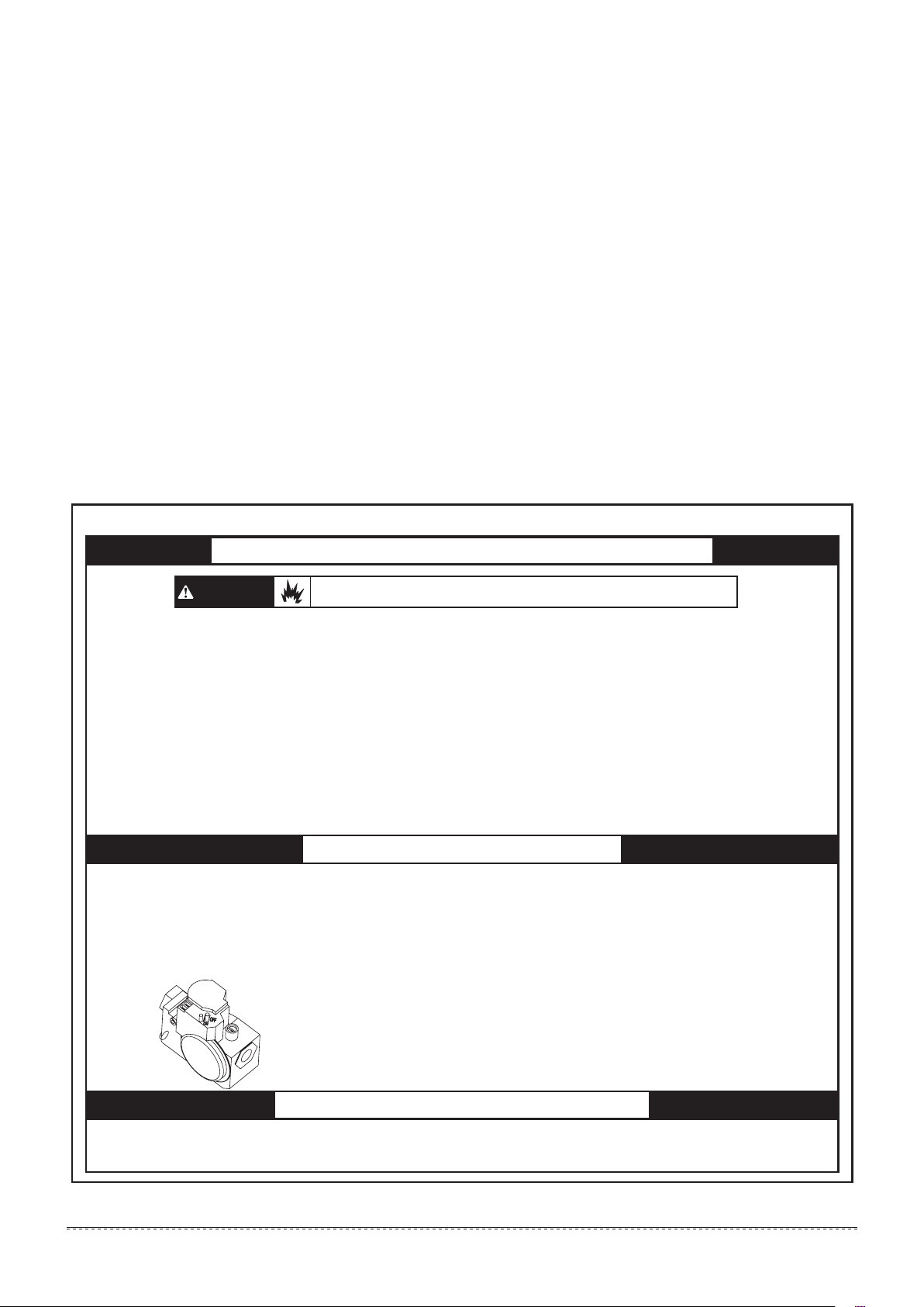
FOR YOUR SAFETY READ BEFORE OPERATING
WARNING
A.
This appliance does not have a pilot. it is equipped with an
ignition device which automatically lights the burner.
Do not try to light the burner by hand.
BEFORE OPERATING smell all around the appliance
B.
area for gas. Be sure to smell next to the floor because
some gas is heavier than air and will settle on the floor.
FOR YOUR SAFETY
WHAT TO DO IF YOU SMELL GAS
• Do not try to light any appliance.
• Do not touch any electrical switch; do not use
any phone in your building.
• Immediately call your gas supplier from a
If you do not follow these instructions exactly, a fire or explosion may result
causing property damage, personal injury or loss of life.
OPERATING INSTRUCTIONS
1. STOP! Read the safety information above on this
label.
2. Set the thermostat to lowest setting.
3. Turn off all electric power to the appliance.
4. This appliance is equipped with an ignition device
which automatically lights the burner. Do not try to
light the burner by hand.
SWITCH SHOWN IN
THE “OFF” POSITION
neighbors’ phone. Follow the gas suppliers
Instructions.
• If you cannot reach your gas supplier, call the
fire department.
Use only your hand to turn the gas control switch. Never use
C.
tools. If the switch will not turn by hand, don’t try to repair it;
call a qualified service technician. Force or attempted repair
may result in a fire or explosion.
Do not use this appliance if any part has been under water.
D.
Immediately call a qualified service technician to inspect the
appliance and to replace any part of the control system and
any gas control which has been under water.
5. Remove control access panel.
6. Wait five (5) minutes to clear out any gas. if you
then smell gas, STOP! Follow “B” in the safety
information above on this label. If you don’t smell
gas, go to the next step.
7. Push gas control switch to “ON”.
NOTE: Do not force.
8. Replace control access panel.
9.Turn on all electric power to the appliance.
10.Set thermostat to desired setting
11.If the appliance will not operate, follow instructions
“To Turn Off Gas To Appliance” and call your
service technician or gas supplier.
TO TURN OFF GAS TO APPLIANCE
1. Set the thermostat to lowest setting.
2. Turn off all electric power to the appliance if service is to be
performed.
See Fig: Instruction of lighting/ shutdown operation. Should the gas supply fail to shut off or if overheating occurs, shut off the gas valve to the
furnace before shutting of the electrical supply.
installation & owner’s manual
3. Remove control access panel.
4. Push gas control to “OFF”. Do not force.
5. Replace control access panel.
6
Page 6
2. INTRODUCTION
A Package Gas Electric Unit is a fully self-contained, combination gas
heating/electric cooling unit designed for outdoor installation. All unit
sizes have return and discharge openings for both horizontal and
downflow configurations, and are factory shipped with all downflow
duct openings covered. Units may be installed either on a rooftop or
on a cement slab.
In gas heating mode, this unit is designed for a minimum continuous
return-air temperature and a maximum continuous return-air
temperature. Failure to follow these return-air temperature limits may
affect reliability of heat exchangers, motors, and other components.
This booklet contains the installation and operating instructions for
your Package Gas Electric Unit. There are some precautions that
should be taken to derive maximum satisfaction from it. Improper
installation can result in unsatisfactory operation or dangerous
conditions. Read this booklet and any instructions packaged with
separate equipment required to make up the system prior to
installation. Give this booklet to the owner and explain its provisions.
The owner should retain this booklet for future reference.
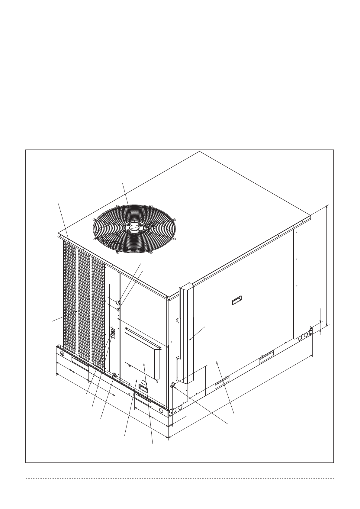
Outdoor fan grille and compressor access
Outdoor coil protective grille
A Package Gas Electric Unit includes a hermetically-sealed
refrigerating system consisting of a compressor, condenser coil,
evaporator coil with thermal expansion valve (TXV) or throttle valve, a
circulation air blower, a condenser fan, a heat exchanger assembly,
gas burner and control assembly, combustion air motor and fan, and
all necessary internal electrical wiring. The cooling system of these
units is factory-evacuated, charged and performance tested. All units
are factory charged with Refrigerant R410A.
Front
6-5/16″
6-5/8″
10″
High pressure detected valve
1/4’’ SAE
Low pressure detected valve
1/4’’ SAE
Condensate drain conn. 3/4” NPTI
(Trap required)
Electrical service access compartment panel
Combustion air inlet hood
2-3/8″
23″
44-5/8″
High voltage conn. 1-23/64” Dia.
Low voltage conn. 7/8” Dia.
20-7/16″
6-5/8″
3-3/4″
6-3/4″
1-3/4″
41-7/16″
2-3/8″
Flue exhaust hood
10-5/16″
57-15/32″
Blower/Evaporator access panel
Gas supply entrance
Fig. 2-1 Unit Dimensions
installation & owner’s manual
7
Page 7
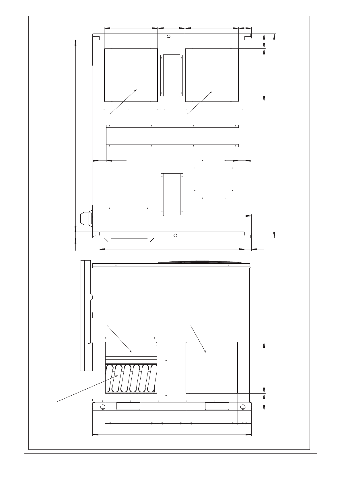
15″ 7-5/8″ 3-5/8″
Bottom supply air opening Bottom return air opening
15″
4-3/16″
15″
53-29/32″1-3/4″
57-15/32″
1-5/8″1-15/16″
Bottom View
1-7/8″40-7/8″
Back View
Heat exchanger
installation & owner’s manual
8
Side supply air opening
44-5/8″
Side return air opening
Fig. 2-2 Dimensions Back and Bottom
4-7/8″ 14-1/2″
14-1/2″14-1/2″ 8-5/32″
3-7/8″
Page 8
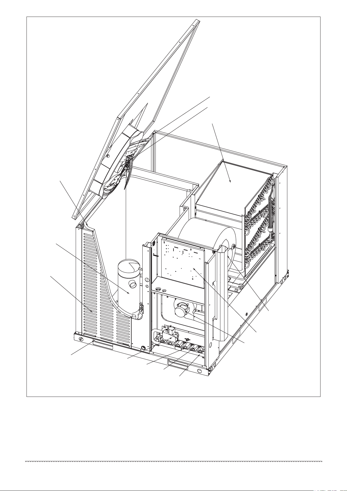
Highly efficient enhanced
microchannel outdoor coil
Compressor
Axial flow fan
Condenser fan motor
Highly efficient enhanced aluminum/copper tube
and aluminum fin indoor coil
Decorative protective
coil guard
Heavy gauge
removable base rails
Blower motor with slide-out
blower assembly
Electrical control box
Combustion air motor and fan
Gas valve
Copper nozzle
Gas burner
Gas tube
Fig. 2-3 Component Location
installation & owner’s manual
9
Page 9
3.0 INSTALLATION
Install the unit in accordance with The American National Standard
Z223.1-latest edition booklet entitled “National Fuel Gas Code”, and
the requirements or codes of the local utility or other authority having
jurisdiction.
Unit should be installed in accordance with national and local safety
codes, including but not limit to ANSI/NFPS No. 70 or Canadian
Electrical Code Part 1, C22.1, local plumbing and wastewater codes
and any other applicable codes.
Additional helpful publications available from the “National Fire
Protection Association” are: NFPA-90A - installation of Air
Conditioning and Ventilating Systems 1985 or latest edition.
NFPA-90B - Warm Air Heating and Air Conditioning Systems 1984.
3.1 PRE-INSTALLATION CHECK-POINTS
Before installation, carefully check the following:
1. For rooftop installation, be sure the structure has enough strength
to support the weight of unit.
2. Clearances and provision for servicing.
3. Power supply and wiring.
4. Gas supply and piping.
5. Air duct connections and sizing.
6. Drain facilities and connections.
7. Location for minimum noise and vibration.
Typical outdoor installation in shown in Figure 3-2:
1. Select a location where external water drainage cannot collect
around unit.
2. Locate unit where operating sounds will not disturb owner or
neighbors.
3. The location of the unit should allow proper access for inspection
and servicing.
4. Locate unit so roof runoff water does not pour directly on the unit.
Provide gutter or other shielding at roof level. Do not locate unit in
an area where excessive snow drifting may occur or accumulate.
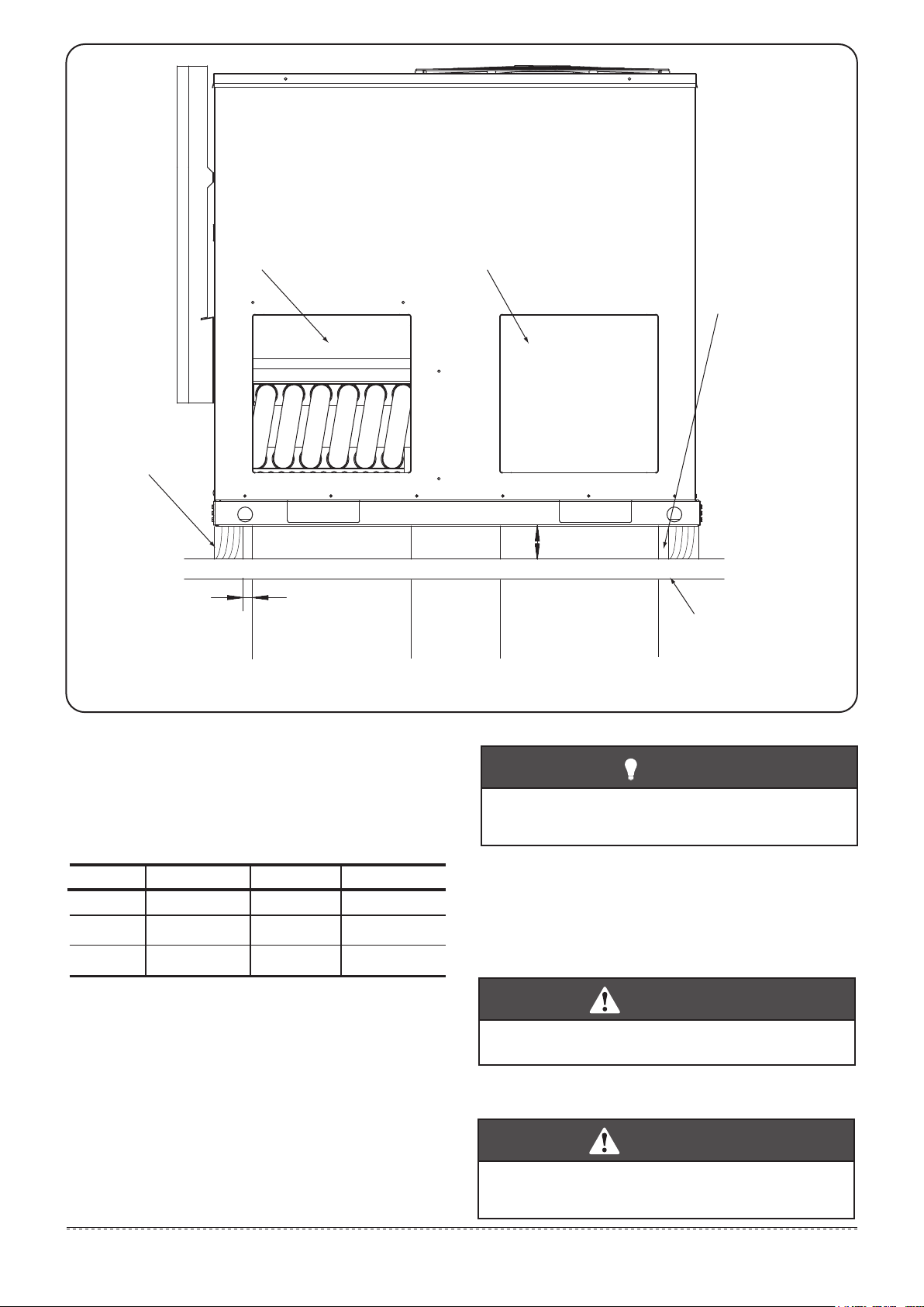
5. Provide a concrete slab extending 3″ beyond all four sides of the
unit. The slab should be sufficiently high enough above grade to
prevent surface water from entering the unit. The slab should be
isolated from the foundation wall.
6. Pitch the slab approximately 1/2″ so that the unit will be pitched
toward the drain. See Figure 3-3.
7. It is essential that the unit be elevated above the base pad to allow
for defrost water runoff, condensate drainage, and possible
refreezing or condensate. Route condensation off the base pad to
an area that will not become slippery and result in personal injury.
Important: Do not interfere with opening in bottom of unit.
8. Where snowfall is anticipated, the height of the unit above the
ground level must be considered. Mount unit high enough to be
above average area snowfall to prevent snow from blocking the
outdoor coil, to allow condensate runoff, and to allow combustion
air to enter the combustion air inlet.
3.2 LOCATION CONSIDERATIONS
The metal parts of the unit may be subject to rust or deterioration in
adverse environmental conditions. This oxidation could shorten the
equipment’s useful life. Salt spray, fog or mist in seacoast areas,
sulphur or chlorine from lawn watering systems, and various chemical
contaminants from industries such as paper mills and petroleum
refineries are especially corrosive.
If the unit is to be installed in an area where contaminants are
likely to be a problem, give special attention to the equipment
location and exposure:
1. Avoid having lawn sprinkler heads spray directly on the unit
cabinet.
2. In coastal areas locate the unit on the side of the building away
from the waterfront.
WARNING
Disconnect all power to the unit before starting maintenance.
Failure to do so can cause electrical shock resulting in personal
injury or death.
3. Shielding by a fence or shrubs may give some protection.
4. Elevate the unit off its slab or base enough to allow air circulation
and avoid holding water against the base pan.
5. Frequent washing of the cabinet, fan blade and coil with fresh water
will remove most of the salt or other contaminants that build up on
the unit.
6. Regular cleaning and waxing of the cabinet with a good automobile
polish will provide some protection.
7. Use a good liquid cleaner several times a year to remove matter
that will not wash off with water.
Several different types of protective coatings are offered in some
areas. These coatings may provide some benefit, but the
effectiveness of such coating materials cannot be verified by the
equipment manufacturer. The best protection is frequent cleaning,
maintenance and minimal exposure to contaminants.
3.3 OUTSIDE INSTALLATION
WARNING
This unit is designed certified for outdoor installation only.
Installation inside any part of a structure can result in inadequate
unit performance as well as property damage. Installation inside
can also cause recirculation of flue products into the conditioned
space resulting in personal injury or death.
3.4 ATTACHING EXHAUST AND COMBUSTiON
AIR INLET HOODS
IMPOPTANT: Do not operate this unit without the exhaust and
combustion air inlet hood property installed. These hoods are
shipped in a carton in the return air compartment inside the unit
and must be attached the unit is installed. See Fig. 2-1.
To attach exhaust and combustion air inlet hood:
1. Remove 3 screws securing filter access panel and remove filter
access panel. For location of filter access panel, see Fig.3-4.
2. Remove both exhaust and combustion air inlet hoods from their
carton, located inside the return air compartment.
3. Attach filter access panel.
4, Attach the combustion air inlet hood and the exhaust hood with 4
and 6 screws as shown in Fig. 2-1. Screws are in parts bag
shipped in the burner compartment.
5. Vent the unit using the flue exhaust hood, as supplied from the
factory, without alteration addition. The only exception is with
factory approved additions. Consult your local unity or other
authority having jurisdiction for accepted venting techniques.
3.5 COVER PANEL INSTAlLATION /
CONVERSION POCEDURE
All unit sizes have return and discharge openings for both horizontal
and downflow configurations, and are factory shipped with all
downflow duct openings covered, HORIZONTAL is factory shipped.
HORIZONTAL TO DOWNFLOW
1. Remove screws and covers from the supply and return bottom
section.
2. Install gasket (supplied with parts bag) around perimeter of cover
on the insulate side.
3. Secure covers to the side of the unit using existing screws and
those supplied in the parts bag. See Fig. 3-4.
4. Seal duct covers with silicone caulk.
DOWNFLOW TO HORIZONTAL
1. Remove screws and covers from the supply and return bottom
section.
2. Install gasket (factory shipped) around perimeter of cover on the
insulate side.
3. Secure covers to the bottom of the unit using existing screws and
those supplied in the parts bag. See Fig. 3-5.
WARNING
This unit must not be installed directly on wood flooring, Class A,
Class B or Class C roof covering materials, or any other
combustion structure except as specified in Fig.3-1. Failure to
adhere to this warning can cause a fire or explosion resulting in
property damage, personal injury or death.
installation & owner’s manual
10
Page 10
Back View
Nominal 4×4 timber
(Sides only)
Sideflow supply
plenum connection
Sideflow return
plenum connection
3-1/2″ MIN
1″ MIN
Supply plenum
(Downflow)
Return plenum
(Downflow)
Fig. 3-1 Exception to non-combustible flooring requirement
Both ends must be
open for downflow or
sideflow ductwork to
provide ventilation
Combustible structure
3.6 CLEARANCE
All units require certain clearance for proper operation and service.
Refer to Table 3-1 for the minimum clearances required for
construction, servicing and proper unit operation.
Table 3-1: Unit Clearance
3
Distance (in.)
24
4
12
0
Direction
1
Top
Front
Rear
Distance (in.)
60
48
2
18
Direction
Right
Left
Bottom
Duct clearance: 1 inch clearance for all sides of air supply duct.
1. Units must be installed outdoors. Over hanging structure or shrubs
should not obscure condenser air discharge outlet.
2. The minimum clearance without economizer/fresh air damper. For
distance with Economizer/fresh air damper, please refer to the
relevant Install requirement.
3. Units may be installed on combustible floors made from wood or
class A, B or C roof covering materials.
4. If Economizer/fresh air damper is used, a 24″ minimum clearance
is required on left side of unit.
NOTE
For units applied with a roof curb, the minimum clearance may
be reduced from 1 inch to 1/2 inch between combustible roof
curb material and this supply air duct.
3.7 RIGGING AND HANDING
Exercise care when moving the unit. Do not remove any packaging
until the unit is near the place of installation. Rig the unit by attaching
chain or cable slings to the lifting holes provided in the base rails.
Spreader bars, whose length exceeds the largest dimension across
the unit, MUST be used across the top of the unit.
CAUTION
Before lifting, make sure the unit weight is distributed equally
on the rigging cables so it will lift evenly.
Units may be moved or lifted with a forklift. Slotted openings in the
base rails are provided for this purpose.
CAUTION
All panels must be secured in place when the unit is lifted.
The condenser coils should be protected from rigging cable
damage with plywood or other suitable material.
installation & owner’s manual
11
Page 11
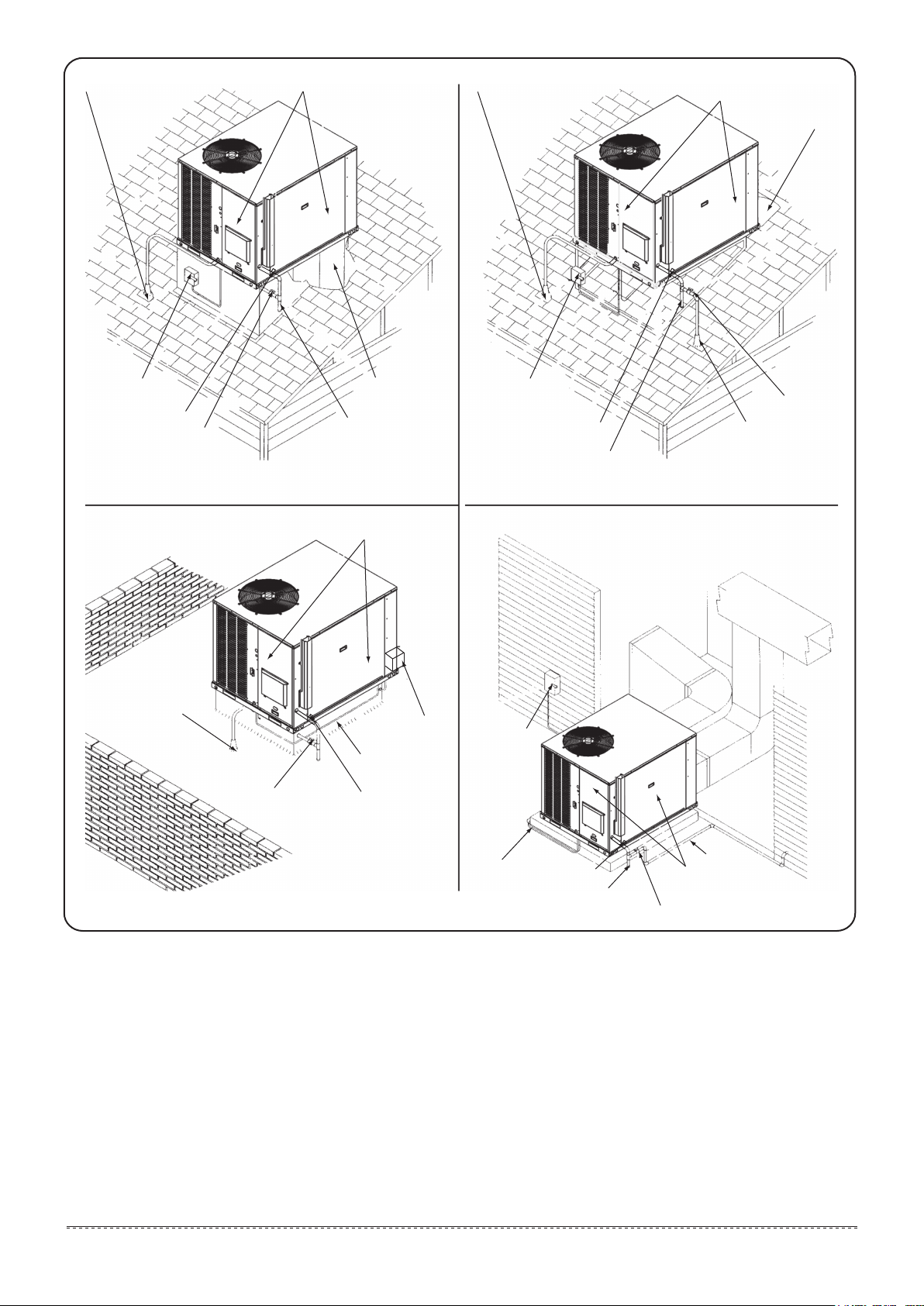
Condensate drain into roof drain
if required by local codes
Service access panels
Do not block access
Condensate drain into roof drain
if required by local codes
Service access panels
Do not block access
Supply plenum
Branch circuit
disconnect
Union
Gas shut-off valve
Condensate drain into roof
drain if required by local codes
Gas shut-off valve
Supply plenum
Trap
Service access panels
Do not block access
Branch circuit
disconnect
Power supply
conduit
Union
Branch circuit
disconnect
Branch circuit
disconnect
Union
Trap
Gas shut-off valve
Gas supply
Supply duct at
closet ceiling
Filter grill
Slab floor
installation & owner’s manual
12
Power supply
conduit
Fig. 3-2 Typical Installations
Union
Trap
Gas supply
Service access panels
Do not block access
Gas shut-off valve
Page 12

Front
This end approx. 1/2″
higher than front
Level plane Condensate drain connection
Fig. 3-3 Slab installation
Filter access panel
(For unit mounted filter
accessory)
Return/Supply duct cover
(attach with 4 screws)
Fig. 3-4 Duct cover installation side mounting
Return/Supply duct cover
(attach with 4 screws)
Fig. 3-5 Duct cover installation base pan mounting
installation & owner’s manual
13
Page 13

Recommended air supply
duct opening size 15”×15”
Recommended air return
duct opening size 15”×15”
40”
7-11/16”
15-5/32”
1”
1”
16-25/32”
4-7/16”
53-9/16”
10-7/16”
15-5/32”
Insulation layer
Front
Supply and return air (including duct support rails)
shown are typical for bottom duct applications.
For location of horizontal duct applications (on back
of unit), refer to unit dimension details.
Fig. 3-6 Roof Curb Dimension
* The above figures for reference purpose only.
NOTE
Be sure to note supply and return openings.
Refer to Fig.3-6, 3-7 for information concerning rear and bottom supply and return air duct openings.
ROOF CURB
On applications when a roof curb is used, the unit must be positioned on the curb so the front of the
unit is tight against the curb. (See Fig. 3-6 ROOF CURB DIMENSION)
installation & owner’s manual
14
Page 14

D
1:2
A-A
D
53-9/16”
1”
1”
A
15-5/32”
B
16-25/32”
4-7/16”
15-5/32”
5/16”
1-3/4”
B-B
A
40”
7-11/16”
B
Fig.3-7 Roof Curb Details
installation & owner’s manual
15
Page 15

3.8 DUCTWORK
Ductwork should be made and sized by installer and in accordance
with Air Manual from Conditioning Contractors of America and local
codes.
NOTE
On ductwork exposed to outside air conditioning space, use at
least 2” of insulation and a vapor barrier. Flexible joint may be
used to reduce noise.
These units are adaptable to horizontal use as well as rear supply and
return air duct openings. To convert to downflow, use the steps is
shown in 3.5.
A closed return duct system shall be used. This shall not preclude use
of economizers or ventilation air intake. Flexible joints may be used in
the supply and return duct work to minimize the transmission of noise.
CAUTION
When fastening duct work to the side duct flanges on the unit,
insert the screws through the duct flanges only. DO NOT insert
the screws through the casing. Outdoor duct work must be
insulation and waterproofed.
NOTE: The Commonwealth of Massachusetts requires the gas
shut-off valve to be a T-handle gas cock.
2. Connect the gas line to the gas pipe inlet opening provided into the
1/2″ inlet valve. See Fig. 4-1 for typical piping.
3. Size the gas line to the furnace adequate enough to prevent undue
pressure drop and never less than 1/2″ nominal pipe size.
4. Install a drip leg or sediment trap in the gas supply line as close to
the unit as possible.
5. Install an outside ground joint union to connect the gas supply to
the control assembly at the burner tray, Unions may not be
installed inside the unit.
6. Gas valves have been factory installed. Install a manual gas valve
where local codes specify a shut-off valve outside the unit casting.
7. Make sure piping is tight. A pipe compound resistant to the action of
liquefied petroleum gases must be used at all threaded pipe
connections.
8. IMPORTANT: Any additions, changes or conversions required for
the furnace to satisfactorily meet the application should be made
by a qualified installer, service agency or the gas supplier, using
factory-specified or approved parts. In the commonwealth of
Massachusetts, installation must be performed by a licensed
plumber or gas fitter for appropriate fuel.
IMPORTANT: Disconnect the furnace and its individual shutoff valve
the gas supply piping during any pressure testing of that system at
test pressures in excess of 1/2 psig or isolate the system from the gas
supply piping system by closing its individual manual shutoff valve
during any pressures equal to or less than 1/2 psig.
Gas line
NOTE
Be sure to note supply and return openings. Refer to Fig. 3 and
4 for information concerning rear and bottom supply and return
air duct openings.
3.9 RETURN AIR
WARNING
Never allow products of combustion to the flue products to
enter the return air ductwork, or the circulating air supply.
All return ductwork must be adequately sealed and
secured to the furnace with sheet metal screws, and joints
taped. All other duct joints must be secured with approved
connections and sealed airtight.
Failure to prevent products of combustion from being
circulated into the living space can create potentially
hazardous conditions, including carbon monoxide
poisoning that could result in personal injury or death.
3.10 FILTERS
The installer must install field supplied filters in the return air duct. A
field installed filter grille is recommended for easy and convenient
access to the filters for periodic inspection and cleaning. Filters must
have adequate face area for the rated air quantity of the unit. See air
delivery tables for recommended filter size.
4.0 GAS SUPPLY, CONDENSATE DRAIN AND
PIPING
4.1 GAS CONNECTION
IMPORTANT: Connect this unit only to gas supplied by a commercial
utility.
1. Install gas piping in accordance with local codes and regulations of
the local utility company. In the absence of local codes, the
installation must conform to the specifications of the National Fuel
Gas Code, ANSI Z223.1 - latest edition.
NOTE: The use of flexible gas connectors is not permitted. If local
codes allow the use of a corrugated stainless steel flexible gas
appliance connector, always use a new listed connector. Do not
use a connector which has previously serviced another gas
appliance.
Manual gas shut-off valve
(Installed Ahead of Ground
Joint Pipe Union)
Drip leg or Trap
Ground Joint Pipe Union
To Be Installed Ahead of
Gas Valve
Gas line to unit
Fig. 4-1 Typical Gas Pipe Arrangement
WARNING
FIRE OR EXPLOSION HAZARD
Failure to follow the safety warnings exactly could result in
serious injury, death of property damage.
Never test for gas leaks with an open flame. Use a commercially
available soap solution made specifically for the detection of
leaks to check all connections. A fire or explosion may result
causing property damage, personal injury or loss of life.
TO CHECK FOR GAS LEAKS, USE A SOAP AND WATER
SOLUTION OR OTHER APPROVED METHOD. DO NOT USE AN
OPEN FLAME.
IMPORTANT: Check the rating plate to make certain the appliance is
equipped to burn the type of gas supplied. Care should be taken after
installation of this equipment that the gas control valve not be
subjected to high gas supply the pressure.
In making gas connections, avoid strains as they may cause noise
and damage the controls. A backup wrench is required to be used on
the valve to avoid damage.
The capacity of gas pipe of different diameters and lengths in CFH
with pressure drop of 0.5 in. and specific gravity of 0.60 (natural gas)
are shown in Table 4-1.
installation & owner’s manual
16
Page 16

Table 4-1: Natural gas pipe capacity table
4.2 LP CONVERSION
(CFH - Cubic Feet of Gas Per Hour)
Nominal iron
pipe size (in.)
1/2 132 92 73 63 56 50 46 43
3/4 278 190 152 130 115 105 96 90
1 520 350 285 245 215 195 180 170
1-1/4 1050 730 590 500 440 400 370 350
1-1/2 1600 1100 890 760 670 610 560 530
After determining the pipe length, select the pipe size which will
provide the minimum cubic feet per hour required for the gas input
rating of the furnace. By formula:
The gas input of the furnace is marked on the furnace rating plate.
The heating value of the gas (BTU/Cubic FT) may be determined by
consulting the local natural gas utility or the L.P. gas supplier.
10 20 30 40 50 60 70 80
CFH=
Heating Value of Gas (BTU/Cubic Foot)
Equivalent length of pipe (ft.)
Furnace input (BTU/HR)
This unit is equipped at the factory for use on Natural Gas only.
Conversion to LP Gas requires a special kit which is included with
the unit. DO NOT BURN ANY LIQUID FUEL OR SOLID FUEL IN
THIS UNIT. Burning any unapproved fuel will result in damage to
this unit heat exchanger, which could result in fire, Carbon
Monoxide poisoning, explosion, personal injury, property
damage or death.
Convert the valve to use liquefied petroleum (LP) gas by replacing the
pressure regulator spring with the conversion kit spring. This LP kit
spring allows the regulator to maintain the proper manifold pressure
for LP gas. The correct burner LP orifices are included in the kit.
NOTE: The LP conversion kit is included with the unit. See
Conversion Kit Index shipped with unit for proper LP kit number.
Furnace conversion to LP gas must be performed by a qualified
technician.
Table 4-2: LP gas pipe capacity table (CFH - Cubic Feet of Gas Per Hour)
WARNING
Nominal iron
pipe size (in.)
1/2 275 189 152 129 114 103 96 89 83 78 69 63
3/4 567 393 315 267 237 217 196 182 173 162 146 132
1 1071 732 590 504 448 409 378 346 322 307 275 252
1-1/4 2205 1496 1212 1039 913 834 771 724 677 630 567 511
1-1/2 3307 2299 1858 1559 1417 1275 1181 1086 1023 976 866 787
2 6221 4331 3465 2992 2646 2394 2205 2047 1921 1811 1606 1496
Example (LP): Input BTU requirement of unit, 150000
Equivalent length of pipe, 60 ft. =3/4″ IPS r
10 20 30 40 50 60 70 80 90 100 125 150
Flame sensor
Temperature sensor
Igniter
Burner Box
Equivalent length of pipe (ft.)
on/off Lever
Gas Valve
Burner
Inlet
Orifice
Gas Manifold
Fig. 4-2 Burner and Gas Valve Arrangement
installation & owner’s manual
17
Page 17

4.3 ADJUSTING OR CHECKING FURNACE INPUT
- Natural Gas Inlet Pressure 5″ -10.5″ W.C.
- LP Gas Inlet Pressure 11″ -13″ W.C.
- Natural Gas Outlet Pressure 3.5″ W.C.
- LP Gas Outlet Pressure 10″ W.C.
Supply and manifold pressure taps are located on the gas valve body
1/8″ N.P.T.
Use a properly calibrated manometer gauge for accurate gas
pressure readings.
Only small variations in the gas flow should be made by means of the
pressure regulator adjustment. Furnaces functioning on LP gas must
be set by means of the tank or branch supply regulators. The furnace
outlet pressure should be set at 10″ W.C. at the gas control valve.
To adjust the pressure regulator, remove the regulator cap and turn
the adjustment screw clockwise to increase pressure or counterclockwise to decrease pressure. Then replace the regulator cap
securely.
Any necessary major changes in the gas flow rate should be made by
changing the size of the burner orifices. To change orifice spuds, shut
off the manual main gas valve and remove the gas manifold.
For elevations up to 2000 feet, rating plate input rating apply. For high
altitudes (elevations over 2000 feet), see conversion kit index for
derating and orifice spud sizes.
Check of input is important to prevent over-firing of the furnace
beyond its designated input, NEVER SET INPUT ABOVE THAT
SHOWN ON THE RATING PLATE. Use the following formula to
determine input rate.
C.F.H. Required=
Start the furnace and measure the time required to burn on cubic foot
of gas. Prior to checking the furnace input, make certain that all other
gas appliances are shut off, with the exception of pilot burners. Time
the meter with only the furnace in operation.
IMPORTANT NOTE FOR ALL ALTITUDES ABOVE 2000 FEET: The
main burner orifices in your furnace and in these kits are sized for the
nameplate input and intended for installations at elevations up to
2000 feet in the USA or Canada, or for elevations of 2000-4500 feet in
Canada if the unit has been derated at the factory. For elevations
above 2000 feet IN THE USA ONLY (see ANSI-Z223.1), the burner
orifices must be sized to reduce the input 4% for each 1000 feet
above sea level.
NOTICE: Derating of the heating input for high altitude in the field is
unlawful in Canada (refer to CAN/CGA 2.17). Units installed in
altitudes greater than 2000 feet must be shipped from the factory or
from a factory authorized conversion station with the heating input
derated by 10% so as to operate properly in altitudes from 2000-4500
feet.
Heating value of gas (BTU/Cubic Ft) ×3600
Time of Seconds (for 1 Cubic Ft.) of gas
4.4 CONDENSATE DRAIN
The evaporator coil condensate drain ends with a threaded 3/4″
nominal PVC stub. A trap is built in for proper condensate drainage
and to prevent debris from being drawn into the unit. Do not connect
the drain to a closed sewer line. It is recommended that a PVC
cement not be used so that the drain line can be easily cleaned in the
future.
IMPORTANT: Do not install an external trap. Doing so can cause
improper drainage of the condensate and result in flooding within the
unit.
5.0 WIRING
5.1 POWER SUPPLY
2. It is important that proper electrical power is available at the unit.
Voltage should not vary more than 10% from that stamped on the
unit nameplate. On three phase units, phases must be balanced
within 3%.
3. For branch circuit wiring (main power supply to unit disconnect), the
minimum wire size for the length of run can be determined from
Table 5-1 using the circuit ampacity found on the unit rating plate.
Use the smallest wire size allowable in Table 5-1 from the
disconnect to unit. The disconnect must be in sight and readily
accessible of the unit.
Table 5-1: Branch circuit copper wire size (in.)
Branch circuit ampacity
15 20 25 30 35 40 45 50
200 6 4 4 4 3 3 2 2
Supply wire
length (Ft.)
NOTES:
1. Wire size based on 60°C rated wire insulation and 30°C Ambient
Temp.
2. For more than 3 conductors in a raceway or cable, see the N.E.C.
for derating the ampacity of each conductor. When installed, the
unit must be electrically grounded in accordance with local codes
or, in the absence of local codes, with the National Electrical Code,
ANSI/NFPA 70, if an external electrical source is utilized.
IMPORTANT: This unit is approved for use with copper
conductors only connected to unit contactor. Warranty may be
jeopardized if aluminum wire is connected to unit contactor.
Special instructions apply for power wiring aluminum
conductors: Warranty is void if connections are not made per
instructions.
Attach a length (6″ or more) of recommended size copper wire to the
unit contactor terminals L1 and L3 for single phase.
Select the equivalent aluminum wire size from the tabulation below:
Splice copper wire pigtails to aluminum wire with U.L. recognized
connectors for copper-aluminum splices. Please exercise the follow
ing instructions very carefully to obtain a positive and lasting
connection:
1. Strip insulation from aluminum conductor.
2. Coat the stripped end of the aluminum wire with the recommended
inhibitor, and wire brush the aluminum surface through inhibitor.
INHIBITORS: Brundy-Pentex ”A”; Alcoa-No. 2EJC; T & B-KPOR
Shield.
3. Clean and recoat aluminum conductor with inhibitor.
4. Make the splice using the below listed wire nuts or split bolt
connectors.
5. Coat the entire connection with inhibitor and wrap with electrical
insulating tape.
AWG Copper
Wire Size
150 8 6 6 4 4 4 3 3
100 10 8 8 6 6 6 4 4
50 14 12 10 10 8 8 6 6
AWG Aluminum
Wire Size
#12 #10 T & B Wire Nut PT2
#10 #8 T & B Wire Nut PT3
#8 #6 Sherman Split Bolt TSP6
#6 #4 Sherman Split Bolt TSP4
#4 #2 Sherman Split Bolt TSP2
Connector Type and Size
(or equivalent)
WARNING
Turn off the main electrical power at the branch circuit disconnect
closest to the unit before attempting any wiring. Failure to do so
can cause electrical shock resulting in personal injury or death.
1. All wiring should be made in accordance with the National Electrical
Code. Consult the local power company to determine the
availability of sufficient power to operate the unit. Check the
voltage at power supply to make sure it corresponds to the unit’s
rated voltage requirement. Install a branch circuit disconnect near
the rooftop, in accordance with the N.E.C., C.E.C. or local codes.
installation & owner’s manual
18
5.2 HOOK-UP
To wire unit, refer to the following Fig. 5-1.
Wiring to be done in the field between the unit and devices not
attached to the unit, or between separate devices which are field
installed and located, shall conform with the temperature limitation for
Type T wire [63°F rise] when installed in accordance with the
manufacturer’s instructions.
Page 18

THERMOSTAT
R
G
Y
W
C
UNIT CONTROL BOX
THERMINAL STRIP
R
G
Y
1
W
C
24 volt
transformer
240V
208V
COM
Fig. 5-1 Typical Field Control Wiring Diagram
CONTACTOR
Field-supplied disconnect
GROUND
LUG
Refer to electrical data tables
to size the disconnect
Single
phase
power
supply
Fig. 6-2 Typical Field Power Wiring Diagram
5.3 INTERNAL WIRING
IMPORTANT: Some single phase units are equipped with a single
pole contactor. Caution must be exercised when servicing as only one
leg of the power supply is broken with the contactor.
Some models are equipped with an electronically commutated blower
motor which is constantly energized unless the main unit disconnect
is in the off position.
A diagram of the internal wiring of this unit is located under the
electrical box cover and in this manual. If any of the original wire as
supplied with the appliance must be replaced, the wire gauge and
insulation must be the same as the original wiring.
Transformer is factory wired for 230 volt on 208/230 volt models and
must be changed to 208 volt applications. See unit wiring diagram for
208 volt wiring.
4. 15 seconds after the pressure switch closes, the gas valve opens
and the spark is initiated for a 7 second trial for ignition.
5. Burners ignite and flame sensor proves all burners have lit.
6. The circulating air blower is energized after 45 seconds.
7. The control board enters a normal operation loop in which all safety
controls are monitored continuously.
8. Thermostat is satisfied and opens.
9. The gas valve is de-energized and closes, shutting down the burner
flame.
10.The control board will de-energized the inducer after a five second
post purge.
11.The circulating air blower BLOWER-LOW is de-energized after
max. 90 seconds.
· The integrated control board has a three times ignition system.
· After a total of 3 trials for ignition without sensing main burner flame,
the system goes into lockout mode.
· After 1 hour, the ignition control repeats the prepurge and ignition
cycles for 3 tries and then goes into lockout mode again.
· It continues this sequence of cycles and lockout each hour until
ignition is successful or power is interupted.
· During the lockout mode, neither the spark ignition control or gas
valve will be energized until the system is reset by turning the
thermostat to the “OFF” position or interrupting the electrical power
to the unit for 3 seconds or longer.
· The induced draft blower and main burner will shut off when the
thermostat is satisfied.
· The circulating air blower will start and run on the heating speed if
the thermostat fan switch is in the ”ON” position.
The integrated furnace control is equipped with diagnostic LED. The
LED is lit continuously when there is power to the control without a call
for heat. If the LED is not lit, there is either no power to the control or
there is an internal component failure within the control, and the
control should be replaced.
If the control detects the following failures, the LED will flash for
designated failure detections.
2 Flash: Failed to detect or sustain flame,system locked out.
3 Flash: Pressure switch or induced draft blower problem detected.
4 Flash: High limit or auxiliary limit open.
5 Flash: Flame sensed and gas valve not energized or flame sensed
with no “W” signal.
6 Flash: Overtemperature switch open.
7 Flash: Thermostat miswired; W1 and W2 swapped.
Slow flash rate:Normal,call for heat.
6.2 OPERATING INSTRUCTIONS
This appliance is equipped with a direct spark intermittent ignition
device. This device lights the main burners each time the room
thermostat (closes) calls for gas heat. See operating instructions on
the back of the furnace/controls access panel.
WARNING
Do not attempt to manually light this furnace with a match or any
open flame. Attempting to do so can cause an explosion or fire
resulting in property damage, personal injury or death.
5.4 THERMOSTAT
The room thermostat must be specifically designed to control
package gas electric units.
6.0 FURNACE SECTION CONTROLS AND
IGNITION SYSTEM
6.1 NORMAL FURNACE OPERATING SEQUENCE
This unit is equipped with an integrated direct spark ignition control.
1. The thermostat calls for gas heat.
2. The control board will run a self check to verify that the limit control
and manual reset overtemperature control are closed and that the
pressure switch is open. If so, the induced draft blower (inducer)
begin a prepurge cycle.
3. The air proving negative pressure switch closes.
6.3 TO START THE FURNACE
1. Set the thermostat to its lowest setting.
2. Turn off all electric power to the appliance.
3. This appliance does not have a pilot. It is equipped with an ignition
device which automatically lights the burner. Do not try to light the
burner by hand.
4. Remove control door.
5. Turn the gas valve to the “OFF” position.
6. Wait five (5) minutes to clear out any gas. Then smell for gas,
including near the floor. If you smell gas, STOP! Follow B in the
safety information on the Operating Instructions located on the
back of the controls/access panel. If you don’t smell gas, go to the
next step.
7. Turn the gas valve to the “ON” position.
8. Replace the control door.
9. Turn on all electric power to the appliance.
10. Set the thermostat to the desired setting.
11. If the appliance will not operate, follow the instructions below to
shut down the furnace.
installation & owner’s manual
19
Page 19

WARNING
The spark ignitor and ignition lead from the ignition control are
high voltage. Keep hands or tools away to prevent electrical
shock. Shut off electrical power before servicing any of the
controls. Failure to adhere to this warning can result in personal
injury or death.
The initial start-up on a new installation may require the control
system to be energized in some time until any air has bled through the
system and fuel gas is available at the burners.
6.4 TO SHUT DOWN FURNACE
1. Set the thermostat to the lowest setting.
2. Turn off all electric power to the appliance if service is to be
performed.
3. Remove control door.
4. Move gas valve to the“OFF”position.
5. Replace control door.
WARNING
Should overheating occur or the gas supply fail to shut off. Shut
off the Manual Gas valve to the appliance before shutting off the
electrical supply. Failure to do so can result in an explosion or fire
causing property damage, severe personal injury or death.
6.5 BURNERS
Burners for these units have been designed so that field adjustment is
not required. Burners are tray-mounted and accessible for easy
cleaning when required.
7.0 SYSTEM OPERATING INFORMATION
7.1 ADVISE THE CUSTOMER
1. Keep the air filters clean. The heating system operates better, more
efficiently and more economically.
2. Arrange the furniture and drapes so that the supply air registers and
the return air grilles are unobstructed.
3. Close doors and windows. This reduces the heating load on the
system.
4. Avoid excessive use of exhaust fans.
5. Do not permit the heat generated by television, lamps or radios to
influence the thermostat operation.
6. Except for the mounting platform, keep all combustible articles
three feet from the unit and exhaust system.
7. IMPORTANT: Replace all blower doors and compartment after
servicing the unit. Do not operate the unit without all panels and
doors securely in place.
8. Do not allow snow or other debris to accumulate in the vicinity of the
appliance.
7.2 FURNACE SECTION MAINTENANCE
The unit’s furnace should operate for many years without excessive
scale build-up in flue passageways; and it should have a qualified
installer, service agency, or gas supplier annually inspect the flue
passageways, the exhaust system and the burners for continued safe
operation, paying particular attention to deterioration from corrosion
or other sources.
If during inspection the flue passageways and exhaust system are
determined to require cleaning, the following procedures should be
followed (by a qualified installer, service agency, or gas supplier):
1. Turn off the electrical power to the unit and set the thermostat to the
lowest temperature.
2. Shut off the gas supply to the unit either at the meter or at manual
valve in the supply piping.
6.6 MANUAL RESET OVERTEMPERATURE CONTROL
A manual reset overtemperature control is located on the burner
shield. This device senses blockage in the heat exchanger or
insufficient combustion air. This shuts off the main burners if
excessive temperatures occur in the burner compartment.
Operation of this control indicates an abnormal condition. Therefore,
the unit should be examined by a qualified installer, service agency, or
the gas supplier before being placed back into operation.
WARNING
DO NOT JUMPER THIS DEVICE! Do not reset the
overtemperature control without taking corrective action to
assure that an adequate supply of combustion air is maintained
under all conditions of operation. Failure to do so can result in
Carbon Monoxide poisoning or death. Replace this control only
with the identical replacement part.
6.7 PRESSURE SWITCH
This furnace has a negative pressure switch for sensing a blocked
exhaust or a failed induced draft blower. It is normally closed when the
induced draft blower starts, indicating air flow through the combustion
chamber.
6.8 LIMIT CONTROL
The supply air high temperature limit cut-off is set at the factory and
cannot be adjusted. It is calibrated to prevent the air temperature
leaving the furnace from exceeding the maximum outlet air
temperature. WARNING: DO NOT JUMPER THIS DEVICE! Replace
this control only with the identical replacement part.
WARNING
Label all wires prior to disconnection when servicing controls.
Wiring errors can cause improper and dangerous operation
resulting in fire ,electrical shock, property damage, personal
injury or death.
3. Remove the furnace controls access panel and the control box
cover.
4. Disconnect the gas supply piping from the gas valve.
5. Disconnect the wiring to the induced draft blower motor, gas valve,
flame sensor, and flame roll-out control, and igniter cable. Mark all
wires disconnected for proper reconnection.
6. Remove the screws (4) connecting the burner tray to the heat
exchanger mounting panel.
7. Remove the burner tray and the manifold assembly from the unit.
8. Remove the screws (4) connecting the induced draft blower to the
collector box and screws (16) connecting the collector box to the
heat exchanger mounting panel. Remove the induced draft blower
and the collector box from the unit.
9. Remove the turbulators from inside the heat exchangers by
inserting the blade of a screwdriver under the locking tabs. Pop the
tabs out of the expanded grooves of the heat exchanger. Slide the
turbulators out of the heat exchangers.
10. Direct a water hose into the outlet of the heat exchanger top. Flush
the inside of each heat exchanger tube with water. Blow out each
tube with air to remove excessive moisture.
11. Reassemble (steps 1 through 10 in reverse order). Be careful not
to strip out the screw holes used to mount the collector box
and inducer blower. Replace inducer blower gasket and
collector box gasket with factory replacements if damaged.
WARNING
installation & owner’s manual
20
Holes in the exhaust transition or heat exchanger can cause toxic
fumes to enter the home. The exhaust transition or heat
exchanger must be replaced if they have holes or cracks in them.
Failure to do so can cause Carbon Monoxide poisoning resulting
in personal injury or death.
Page 20

The manufacturer recommends that a qualified installer, service
agency or the gas suppler visually inspect the burner flames for the
desired flame appearance at the beginning of the heating season and
approximately midway in heating season.
The manufacturer also recommends that a qualified installer, service
agency or the gas supplier clean the flame sensor with steel wool at
the beginning of the heating season.
WARNING
Disconnect main electrical power to the unit before attempting
maintenance. Failure to do so may result in electrical shock or
severe personal injury or death.
7.3 LUBRICATION
IMPORTANT: DO NOT attempt to lubricate the bearings on the blower
motor or the induced draft blower motor. Addition of lubricants can
reduce the motor life and void the warranty.
The blower motor and induced draft blower motor are prelubricated by
the manufacturer and do not require further attention.
A qualified installer, service agency or the gas supplier must
periodically clean the motors to prevent the possibility of overheating
due to an accumulation of dust and dirt on the windings or on the
motor exterior. And, as suggested elsewhere in these instruct ions,
the air filters should be kept clean because dirty filters can restrict air
flow and the motor depends upon sufficient air flowing across and
through it to prevent overheating.
7.4 COOLING SECTION MAINTENANCE
It is recommended that at the beginning of each cooling season a
qualified installer or service agency inspect and clean the cooling
section of this unit. The following areas should be addressed:
evaporator coil, condenser coil, condenser fan motor and venturi
area.
To inspect the evaporator coil:
1. Remove the filter access panel and the blower/evaporator coil
access panel.
WARNING
Label all wires prior to disconnection when servicing controls.
Wiring errors can cause improper and dangerous operation
resulting in fire ,electrical shock, property damage, personal
injury or death.
2. Unplug the wires from the circulating air blower and the limit control.
Remove the two screws and slide the blower out of the unit
sideways.
3. Shine a flashlight on the evaporator coil (both sides) and inspect for
accumulation of lint, insulation, etc.
4. If coil requires cleaning, follow the steps shown below.
Cleaning Evaporator Coil, Drain Pan,
Condensate Drain, Condenser Fan, Circulation
Air Blower and Venturi
1. Remove the screws from the filter access panel and the
blower/evaporator coil access panel from the unit. Remove the
filter access panel and the blower/evaporator coil access panel.
2. The coil should be cleaned when it is dry. If the coil is coated with
dirt or lint, vacuum it with a soft brush attachment. Be careful not to
bend the Coil fins.
3. If the coil is coated with oil or grease, clean it with a mild
detergent-and-water solution. Rinse the coil thoroughly with water.
IMPORTANT: Do not use excessive water pressure. Excessive
water pressure can bend the tins and tubing of the coil and lead to
inadequate unit performance. Be careful not to splash water
excessively into unit.
4. Inspect the drain pan and condensate drain at the same time the
evaporator coil is checked. Clean the drain pan by flushing with
water and removing any matters of obstructions which may be
present.
5. Flush the drain tube with water. If the drain tube is blocked, it can
usually be cleared with high pressure water.
6. The venturi should also be inspected for items of obstruction such
as collections of grass, dirt or spider webs. Remove any that are
present.
7. Inspect the circulating air blower wheel and motor for accumulation
of lint, dirt or other obstruction and clean if necessary. Inspect the
blower motor mounts and the blower housing for loose mounts or
other damage. Repair or replace it necessary.
Re-assembly
1. Place the condenser coil protective grille back on unit and replace
all screws.
2. Place top panel back on unit and replace all screws.
3. Set condenser fan grille assembly on top of the unit with the fan on
top and the motor wires on the venturi side. Run the fan motor
wires through the bulkhead and pull wires through the hole on the
bottom of the control box on the left side and into the control box.
Reconnect fan motor wires per the wiring diagram attached to the
back of the control box cover.
4. Replace wire strain relief in bulkhead after the slack is pulled out of
the wires on the fan side. This will assure wires will not be
damaged by the fan during unit operation.
5. Turn the condenser fan grille assembly over and into the recess in
the unit top. Secure the grille to the unit with the four long #8
screws removed earlier.
6. Replace the circulating air blower, making sure that all wires are
properly reconnected per the unit wiring diagram.
7. Replace the filter and blower/evaporator coil access panels.
8. Replace the control box cover and controls access panel.
9. Restore electrical power to the unit and check for proper operation,
especially the condenser fan motor.
7.5 REPLACEMENT PARTS
Contact your local distributor for a complete parts list.
Cleaning Condenser Coil
1. Remove screws from condenser fan grille assembly and lay grille
over on the unit top panel.
2. Remove the controls access panel and the control box cover.
3. Disconnect the outdoor fan motor wiring from the compressor
contactor and capacitor. Remove the strain relief in the bulkhead
and pull the fan motor wires through. Set grille assembly to the
side.
4. Remove the screws that secure the unit top to the unit. Remove the
top and set the unit top to the side.
5. The coil should be cleaned when it is dry. If the coil is coated with
dirt or lint, vacuum it with a soft brush attachment. Be careful not to
bend the coil fins.
6. If the coil is coated with oil or grease, clean it with a mild
detergent-and-water solution. Rinse the coil thoroughly with water.
IMPORTANT: Do not use excessive water pressure. Excessive
water pressure can bend the fins and tubing of the coil and lead to
inadequate unit performance. Be careful not to splash water
excessively into unit.
7. Go to next section for cleaning the evaporator coil.
7.6 TROUBLE SHOOTING
Refer to Troubleshooting Chart included in this manual.
7.7 WIRING DIAGRAMS
Refer to the appropriate wiring diagram included in this manual.
7.8 CHARGING
Refer to the appropriate charge chart included in this manual.
7.9 BLOWER MOTOR SPEED TAPS
After determining necessary CFM and speed tap data, follow the
steps below to change speeds.
1. Remove control door.
2. Please refer to the Table 10-1 & Table 10-2 and wiring
the proper location of the wire on the speed tap block of the indoor
blower motor to obtain the speed you have chosen.
3. After adjusting the wires accordingly,replace control door.
installation & owner’s manual
diagram
for
21
Page 21

8.0 OPERATION
Most single phase units are equipped with Permanent Split Capacitor
(PSC) motors (no start relay or start capacitor). It is important that
such systems be off for a minimum of 5 minutes before restarting to
allow equalization of pressures. Do not move the thermostat to cycle
unit without waiting five minutes. To do so may cause the compressor
to stop on an automatic open overload device or blow a fuse. Poor
electrical service can cause nuisance tripping in overloads or blow
fuses.
IMPORTANT: The compressor has an internal overload protector.
Under some conditions, it can take up to 2 hours for this overload to
reset. Make sure overload has had time to reset before condemning
the compressor.
The control allows the blower to operate for up to 90 seconds after the
thermostat is satisfied.
8.1 CONTROL SYSTEM OPERATION
1. Heating mode
The wall thermostat “calls for heat,” closing the R--to--W circuit. The
furnace control performs a “NORMAL FURNACE OPERATING
SEQUENCE”.
2.Cooling mode
In the cooling mode, The thermostat closes the R--to--G--and-- Y
circuits. The thermostat will energize the compressor contactor
and the indoor blower relay. the blower motor will operate on
BLOWER-SINGLE/HI speed,After the thermostat is satisfied, the
compressor is de-energized and the cool mode delay-to-fan-off
period begins. After the delay-to-fan- off period ends, the circulator
fan is de-energized. The indoor blower can be operated
continuously by setting the thermostat fan switch at the “ON”
position.
3. Fan mode
When the circuit R--to--G is closed by the thermostat, the blower
motor will operate on BLOWER-LOW speed , If the thermostat
fan switch is moved to the ON position, the circulator fan
will be energized. When the fan switch is returned to the AUTO
position, the circulator fan will be de-energized.
8.2 FAN DELAY ADJUSTMENT
As shipped, the circulator blower fan will remain on for 90 seconds
after the gas valve closes. When a call for cooling occurs,the
circulator fan comes on and remains on for 80 seconds after the
call for cooling ends. During normal heating operation, the circulator
fan will come on approximately 45 seconds after the gas valve opens.
60
90
*
HEAT
COOL
*
0
80
*
TES YROTCAF
installation & owner’s manual
22
01047805631X#
75430TNC
Page 22

9.0 PHYSICAL DATA
Table 9-1: 14 SEER Physical Data
Component
Nominal Tonnage 2.5 3.0
ARI COOLING PERFORMANCE
Gross Capacity @ ARI A point (Btu) 29521 36570
ARI net capacity (Btu) 28600 35000
EER 11.0 11.0
SEER 14 14
Nominal CFM 1050 1300
System power (kW) 2.60 3.18
Refrigerant type R410a R410a
Refrigerant charge (lb-oz) 4-7
GAS HEATING PERFORMANCE
Heating input (Btu) 60000 90000
Heating output (Btu) 48600 72900
Temperature rise range (0F) 25-55 25-55
AFUE (%) 81 81
Steady state efficiency (%) 81 81
No. burners 3 4
No. stages 1 1
Gas connection pipe size (in.) 1/2 1/2
DIMENSIONS (Inches)
gth 57-15/32 57-15/32
Len
Width 44-5/8 44-5/8
Height 41-7/16 41-7/16
OPERATING WT. (lbs) 500 531
COMPRESSORS
Type Rotate Scroll
Quantity 1 1
CONDENSER COIL DATA
Face area (Sq. Ft) 17.7 17.7
Rows
Fin type
EVAPORATOR COIL DATA
Face area (Sq. Ft) 6.53 6.53
Rows 3 3
Fins per inch 14 14
Tube diameter 3/8 3/8
Circuitry type interlaced interlaced
Refrigerant control Orifice Orifice
CONDENSER FAN DATA
Fan diameter (inch) 22 22
Type Prop Prop
Drive type Direct Direct
No. speeds 1 1
Number of motors 1 1
Motor HP each 1/6
RPM 845
Nominal total CFM 3000
DIRECT DRIVE EVAP FAN DATA
Quantity 1 1
Fan Size (Inch) 10×8 11×8
Type Centrifugal Centrifugal
No. speeds 4 4
Motor HP each 1/2 3/4
RPM 1075 1075
Motor frame size 48 48
J4PG4024A1060AA
2.0
23517
22800
11.0
14
850
2.07
R410a
3-12
60000
48600
35-65
81
81
3
1
1/2
57-15/32
44-5/8
41-7/16
481
Rotate
1
17.7
1
4.35
3
14
3/8
interlaced
Orifice
22
Prop
Direct
1
1
1/12
1075
2500
1
10×8
Centrifugal
4
1/3
1075
48
J4PG4030A1060AA J4PG4036A1090AA
4-1
1 1
Microchannel condenser coil
1/6
845
000
3
Models
J4PG4042A1090AA
3.5
42570
41000
11.0
14
1400
3.73
R410a
6-12
90000
72900
25-55
81
81
4
1
1/2
57-15/32
44-5/8
41-7/16
582
Scroll
1
17.7
1
8.7
3
16
5/16
interlaced
Orifice
22
Prop
Direct
1
1
1/3
1100
3000
1
11×8
Centrifugal
4
3/4
1075
48
installation & owner’s manual
23
Page 23

Table 9-1: 14 SEER Physical Data (Continued)
Component
Nominal Tonnage 4.0 5.0 5.0
ARI COOLING PERFORMANCE
Gross Capacity @ ARI A point (Btu) 48911 58860 58860
ARI net capacity (Btu) 47000 57000 57000
EER
SEER 14 14 14
Nominal CFM 1600 1750 1750
System power (kW) 4.36 5.18 5.18
Refrigerant type R410a R410a R410a
Refrigerant charge (lb-oz) 7-1 5-6 5-6
GAS HEATING PERFORMANCE
Heating input (Btu) 90000 90000 130000
Heating output (Btu) 72900 72900 105300
Temperature rise range (0F) 25-55 25-55 35-65
AFUE (%) 81 81 81
Steady state efficiency (%) 81 81 81
No. burners 4 4 6
No. stages 1
Gas connection pipe size (in.) 1/2 1/2 1/2
DIMENSIONS (Inches)
Length 57-15/32 57-15/32 57-15/32
Width 44-5/8 44-5/8 44-5/8
Height 41-7/16 41-7/16 41-7/16
OPERATING WT. (lbs) 584 606 628
COMPRESSORS
Type Scroll Scroll Scroll
Quantity 1 1 1
CONDENSER COIL DATA
Face area (Sq. Ft) 17.7 17.7 17.7
Rows 1 1 1
Fin type
EVAPORATOR COIL DATA
Face area (Sq. Ft) 8.7 8.7 8.7
Rows 3 3 3
Fins per inch 14 16 16
Tube diameter 3/8 5/16 5/16
Circuitry type interlaced interlaced interlaced
Refrigerant control Orifice Orifice Orifice
CONDENSER FAN DATA
Fan diameter (inch) 22 22 22
e Prop Prop Prop
Typ
Drive type Direct Direct Direct
No. speeds 1 1 1
Number of motors 1 1 1
Motor HP each 1/3 1/3 1/3
RPM 1100 1100 1100
Nominal total CFM 3000 3680 3680
DIRECT DRIVE EVAP FAN DATA
Quantity 1 1 1
Fan Size (Inch) 12×9 12×9 12×9
Type Centrifugal Centrifugal Centrifugal
No. speeds 5 5 5
Motor HP each 3/4 3/4 3/4
RPM 1050 1050 1050
Motor frame size 48 48 48
J4PG4048A1090AA J4PG4060A1090AA J4PG4060A1130AA
11.0 11.0 11.0
1 1
Microchannel condenser coil
Models
installation & owner’s manual
24
Page 24

10.0 AIRFLOW PERFORMANCE
Airflow performance data is based on cooling performance with a coil and no filter in place. Use this performance
table for appropriate unit size, external static applied to unit and allow operation within the minimum and maximum
limits shown in table below for both cooling and electric heat operation.
Table 10-1 Indoor Airflow Performance - 230 Volts
Model
J4PG4024A1060AA
1/3HP PSC motor
J4PG4030A1060AA
1/2HP PSC motor
J4PG4036A1090AA
3/4HP PSC motor
Motor Speed
Low
Middle-Low
Middle-High
High
Low
Middle-Low
Middle-High
High
Low
Middle-Low
Middle-High
High
External Static Pressure-Inc hes W.C.
0 0.1 0.2 0.3 0.4 0.5 0.6 0.7 0.8
CFM 647 587
RPM 480 540
Watts 148 145
Amps 0.66 0.64
CFM 906 848 794 737 681 621 555
RPM 650 700 740 780 830 870 910
Watts 246 240 234 227 219 212 204
Amps 1.08 1.05 1.02 0.99 0.95 0.92 0.89
CFM 1008 958 909 864 798 729 661
RPM 730 770 800 840 870 910 940
Watts 290 282 274 268 259 249 240
Amps 1.26 1.23 1.19 1.17 1.13 1.08 1.05
CFM 1038 983 910 828 747 651
RPM 950 970 990 1010 1030 1050
Watts 352 345 332 318 305 294
Amps 1.54 1.51 1.46 1.4 1.35 1.3
CFM 917 859 806 753 694
RPM 664 714 768 807 853
Watts 254 249 243 236 229
Amps 1.11 1.09 1.06 1.03 0.99
CFM 1190 1117 1049 980 910 835 752
RPM 869 893 921 945 968 991 1011
Watts 340 332 323 315 306 296 286
Amps 1.52 1.49 1.47 1.44 1.42 1.39 1.36
CFM 1306 1226 1153 1083 1005 926 839 738
RPM 938 959 977 996 1012 1029 1043 1058
Watts 426 416 406 396 386 375 364 352
Amps 1.94 1.91 1.89 1.86 1.83 1.8 1.77 1.74
CFM 1295 1217 1133 1055 974 884 793 689
RPM 990 1005 1021 1035 1047 1060 1071 1082
Watts 480 469 457 445 434 423 411 400
Amps 2.2
CFM 1034 982 932 885 838
RPM 645 687 725 763 794
Watts 412 398 385 373 362
Amps 1.93 1.9 1.87 1.85 1.82
CFM 1401 1339 1283 1223 1164 1100 1035 968 888
RPM 864 879 900 919 936 953 969 982 1002
Watts 458 449 439 429 419 409 399 388 375
Amps 2.15 2.13 2.11 2.08 2.06 2.03 2.01 1.98 1.95
CFM 1535 1465 1402 1343 1277 1216 1145 1072 996
RPM 938 951 967 976 989 1002 1014 1025 1036
Watts 551 544 528 517 506 495 483 470 459
Amps 2.7 2.67 2.64 2.62 2.59 2.56 2.53 2.5 2.47
CFM 1588 1516
RPM 1014 1021 1030 1038 1046 1054 1062 1069
Watts 674 659 648 636 623 611 598 583
Amps 3.47 3.43 3.4 3.37 3.34 3.31 3.27 3.23
3 2.2 2.17 2.13 2.1 2.07 2.04 2.01
1453 1383 1313 1249 1170 1087
installation & owner’s manual
25
Page 25

Table 10-1 Indoor Airflow Performance - 230 Volts (Continued)
Model
J4PG4042A1090AA
3/4HP PSC motor
J4PG4048A1090AA
3/4HP X13 DC motor
J4PG4060A1090AA
J4PG4060A1130AA
3/4HP DM2XFS DC motor
* The above airflow data for reference only.
Motor Speed
Low
Middle-Low
Middle-High
High
Low
Middle-1
Middle-2
Middle-3
High
Low
Middle-1
Middle-2
Middle-3
High
0 0.1 0.2 0.3 0.4 0.5 0.6 0.7 0.8
CFM 988 946
RPM 600 645
Watts 427 414
Amps 2 1.9
CFM 1390 1339 1286 1234 1179 1125 1064 1000
RPM 826 855 873 897 914 933 950 971
Watts 479 463 454 446 436 425 414 403
Amps 2.2 2.1 2.1 2.1 2.1 2 2 2
CFM 1544 1485 1435 1380 1322 1256 1189 1124 1045
RPM 913 927 944 959 963 974 990 1004 1015
Watts 578 566 556 539 529 514 502 491 476
Amps 2.7 2.7 2.6 2.6 2.6 2.5 2.5 2.5 2.4
CFM 1683 1628 1564 1494 1433 1370 1307 1227 1151
RPM 993 999 1010 1022 1031 1041 1050 1057 1066
Watts 710 701 684 675 656 645 633 615 601
Amps 3.5 3.4 3.4 3.4 3.3 3.3 3.3 3.2 3.2
CFM
RPM
Watts
Amps
CFM
RPM
Watts
Amps
CFM
RPM
Watts
Amps
CFM
RPM
Watts
Amps
CFM
RPM
Watts
Amps
CFM
RPM
Watts
Amps
CFM
RPM
Watts
Amps
CFM
RPM
Watts
Amps
CFM
RPM
Watts
Amps
CFM
RPM
Watts
Amps
1450 1403 1355 1296 1254 1212 1163
770 804 834 863 891 915 936
320 331 343 351 362 373 377
2.4 2.47 2.53 2.59 2.66 2.73 2.76
1564 1514 1466 1420 1372 1332 1289 1251 1210
833 856 884 912 940 965 985 1008 1030
396 40
2.87 2.91 3.01 3.1 3.19 3.27 3.31 3.37 3.44
1640 1594 1548 1505 1452 1415 1376 1338 1302
871 901 925 950 978 1003 1021 1042 1060
457 470 483 495 510 520 527 538 546
3.28 3.36 3.45 3.54 3.62 3.69 3.73 3.8 3.87
1790 1744 1704 1661 1621 1578 1535 1482 1427
953 975 997 1020 1042 1068 1091 1101 1114
599 612 625 637 650 661 672 670 657
4.22 4.32 4.4 4.49 4.57 4.64 4.71 4.69 4.63
1876 1843 1792 1751 1711 1647 1582 1521 1458
996 1019 1046 1064 1083 1098 1111 1118 1124
706 715 734 744
4.89 4.98 5.09 5.16 5.22 5.18 5.05 4.94 4.83
1553 1493 1436 1382 1329 1270 1206
857 882 913 941 965 991 1018
263 272 282 292 302 313 318
1.91 1.97 2.04 2.11 2.18 2.26 2.29
1673 1620 1555 1507 1454 1392 1339 1273 1208
924 944 968 992 1014 1041 1064 1082 1101
333 346 356 364 372 381 389 396 400
2.39 2.47 2.54 2.6 2.65 2.71 2.76 2.81 2.84
1771 1720 1659 1602 1555 1493 1434 1377 1312
983 1005 1018 1035 1060 1078 1105 1119 1142
417 426 434 444 446 453 457 461 466
2.96 3.02 3.08 3.12 3.14 3.19 3.22 3.25 3.28
1923 1872 1817 1758 1704 1656 1601 1545 1
1062 1074 1093 1112 1128 1143 1163 1186 1204
563 569 575 581 587 594 597 599 608
3.92 3.96 3.99 4.03 4.07 4.11 4.14 4.15 4.21
2033 1975 1919 1870 1814 1763 1715 1655 1601
1113 1118 1142 1161 1175 1188 1208 1222 1241
664 675 682 688 694 702 712 719 729
4.59 4.66 4.7 4.74 4.78 4.83 4.89 4.93 5
External Static Pressure-Inc hes W.C.
3 417 429 443 453 459 470 481
751 745 729 712 691
492
installation & owner’s manual
26
Page 26

Table 10-2 Motor Speed from factory
Cooling Gas Heat
Model
J4PG4024A1060AA All Middle-Low Middle-Low 10×8 1/3 35-65
J4PG4030A1060AA All Middle-Low Low 10×8
J4PG4036A1090AA All Middle-Low Middle-Low
J4PG4042A1090AA
J4PG4048A1090AA
J4PG4060A1090AA
J4PG4060A1130AA
Usable Motor
Speed
All Middle-Low Middle-Low 11×8 3/4 25-55
All Middle-3 Middle-1 12×9
All Middle-3 High 12×9 3/4 35-65
Motor Speed
from f actory
Usable Motor Speed
Middle-Low
Middle-High
High
Low
Middle-Low
Middle-High
Middle-Low
Middle-High
High
Middle-Low
Middle-High
High
Low
Middle-1
Middle-2
Low
Middle-1
Middle-2
Middle-2
Middle-3
High
Motor Speed
from f actory
Blower Size Motor HP
1/2 25-55
11×8 3/4 25-55
3/4 25-55All Middle-2 Middle-1 12×9
3/4 25-55
Temperature rise
range (℉)
● The air distribution system has the greatest effect on airflow. The duct system is totally controlled by the contractor. For this
reason, the contractor should use only industry-recognized procedures.
● Each ton of cooling requires between 350 and 450 cubic feet of air per minute (CFM), or 400 CFM nominally.
● Duct design and construction should be carefully done. System performance can be lowered dramatically through bad planning
or workmanship.
● Air supply diffusers must be selected and located carefully. They must be sized and positoined to deliver treated air along the
perimerter of the space. If they are too small for their intended airflow, they become noisy. If they are not located properly, they
cause drafts. Return air grilles must be properly sized to carry air back to the blower. If they are too small, they also cause
noise.
● The installers should balance the air distribution system to ensure proper quiet airflow to all rooms in the home. This ensures a
comfortable living space.
● An air velocity meter or airflow hood can give a reading of system CFM.
● When installation, installer should select the air speed according to the actual setting static pressure. Please refer to the Table
10-1 & Table 10-2.
installation & owner’s manual
27
Page 27

Table 10-3 Refrigerant charge for 24K A/C system
105
24K
Cooling Charge Chart/Tableau De Charge de Refroidissement
Outdoor Ambient Temperature(°F)/Temperature Amdiante Exterieure(en F)
High Pressure Detected Valve(psig)/Vanne Détecté de Pression Haute(en psig)
105
30K
Cooling Charge Chart/Tableau De Charge de Refroidissement
Cooling Mode
Outdoor Ambient Temperature(°F)/Temperature Amdiante Exterieure(en F)
Mode
De Refroidissement
High Pressure Detected Valve(psig)/Vanne Détecté de Pression Haute(en psig)
105
36K
Cooling Charge Chart/Tableau De Charge de Refroidissement
Cooling Mode
Outdoor Ambient Temperature(°F)/Temperature Amdiante Exterieure(en F)
Mode
De Refroidissement
High Pressure Detected Valve(psig)/Vanne Détecté de Pression Haute(en psig)
Cooling Mode
Mode
De Refroidissement
165
161
157
153
149
145
141
137
133
129
125
121
Low Pressure Detected Valve(psig)
117
113
109
Vanne Détectée de Pression Basse(en psig)
55 60 65 70 75 80 85 90 95 100 105 110 115
269 288 307 326 349 371 393 414 435 456 476
269 288 307 326 349 371 393 414 434 454 474
267 286 305 324 347 369 391 412 432 452 472
245 265 284 303 322 3 45 367 389 410 430 450 470
243 263 282 301 320 3 43 365 387 408 428 448 468
241 261 280 299 318 3 41 363 385 406 426 446 466
220 239 259 278 297 3 16 339 361 383 404 424 444 46 4
218 237 257 276 295 3 14 337 359 381 402 422 442 46 2
216 235 255 274 293 3 12 335 357 379 400 420 440 46 0
214 233 253 272 291 3 10 333 355 377 398 418 438 45 8
212 231 251 270 289 3 08 331 353 375 396 416 436
210 229 249 268 287 3 06 329 351 373 394 414 434 45 4
208 227 247 266 285 3 04 327 349 371 392 412 432 45 2
206 225 245 264 283 3 02 325 347 369 390 410 430 45 0
204 223 243 262 281 3 00 323 345 367 388 408 428 44 8
202 221 241 260 279 2 98 321 343 365 386 406 426 44 6
Table 10-4 Refrigerant charge for 30K A/C system
456
55 60 65 70 75 80 85 90 95 100 105 110 115
165
161
157
153
149
145
141
137
133
129
125
121
Low Pressure Detected Valve(psig)
117
113
109
Vanne Détectée de Pression Basse(en psig)
219 239 259 280 300 321 340 360 380 401 421 442 462
217 237 257 278 298 319 338 358 378 399 419 440 460
215 235 255 276 296 317 336 356 376 397 417 438 458
213 233 253 274 294 315 334 354 374 395 415 436 456
211 231 251 272 292 313 332 352 372 393 413 434 454
209 229 249 270 290 311 330 350 370 391 411 432 452
207 227 247 268 288 309 328 348 368 389 409 430 450
205 225 245 266 286 307 326 346 366 387 407 428 448
203 223 243 264 284 305 324 344 364 385 405 426 446
201 221 241 262 282 303 322 342 362 383 403 424 444
245 265 286 306 327 346 366 386 407 427 448 468
243 263 284 304 325 344 364 384 405 425 446 466
241 261 282 302 323 342 362 382 403 423 4
269 290 310 331 350 370 390 411 432 453 474
269 290 310 331 350 370 390 411 431 452 472
267 288 308 329 348 368 388 409 429 450 470
Table 10-5 Refrigerant charge for 36K A/C system
55 60 65 70 75 80 85 90 95 100 105 110 115
165
161
157
153
149
145
141
137
133
129
125
121
Low Pressure Detected Valve(psig)
117
113
109
Vanne Détectée de Pression Basse(en psig)
223 243 263 28 4 304 325 349 373 397 41 9 442 464 486
221 241 261 28 2 302 323 347 371 395 41 7 440 462 484
219 239 259 28 0 300 321 345 369 393 41 5 438 460 482
217 237 257 27 8 298 319 343 367 391 41 3 436 458 480
215 235 255 27 6 296 317 341 365 389 41 1 434 456 478
213
211 231 251 27 2 292 313 337 361 385 40 7 430 452 474
209 229 249 27 0 290 311 335 359 383 40 5 428 450 472
207 227 247 26 8 288 309 333 357 381 40 3 426 448 470
205 225 245 26 6 286 307 331 355 379 40 1 424 446 468
249 269 290 31 0 331 355 379 403 425 44 8 470 492
247 267 288 30 8 329 353 377 401 423 44 6 468 490
245 265 286 30 6 327 351 375 399 421 44 4 466 488
233 253 274 29 4 315 339 363 387 409 43 2 454 476
273 29
273 294 314 33 5 359 383 407 429 452 47 4 496
271 292 312 33 3 357 381 405 427 450 47 2 494
4 314 335 359 383 407 430 453 47 5 498
44 464
installation & owner’s manual
28
Page 28

105
48K
Cooling Charge Chart/Tableau De Charge de Refroidissement
Cooling Mode
Outdoor Ambient Temperature(°F)/Temperature Amdiante Exterieure(en F)
Mode
De Refroidissement
High Pressure Detected Valve(psig)/Vanne Détecté de Pression Haute(en psig)
105
60K
Cooling Charge Chart/Tableau De Charge de Refroidissement
Cooling Mode
Outdoor Ambient Temperature(°F)/Temperature Amdiante Exterieure(en F)
Mode
De Refroidissement
High Pressure Detected Valve(psig)/Vanne Détecté de Pression Haute(en psig)
Table 10-6 Refrigerant charge for 42K A/C system
105
42K
Cooling Charge Chart/Tableau De Charge de Refroidissement
Cooling Mode
Outdoor Ambient Temperature(°F)/Temperature Amdiante Exterieure(en F)
Mode
De Refroidissement
High Pressure Detected Valve(psig)/Vanne Détecté de Pression Haute(en psig)
214 236 259 281 304 327 349 370 402 427 452 477 502
55 60 65 70 75 80 85 90 95 100 105 110 115
165
161
157
153
149
145
141
137
133
129
125
121
Low Pressure Detected Valve(psig)
117
113
109
Vanne Détectée de Pression Basse(en psig)
216 235 255 274 293 313 337 361 385 407 429 4 50 472
214 233 253 272 291 311 335 359 383 405 427 4 48 470
212 231 251 270 289 309 333 357 381 403 425 4 46 468
210 229 249 268 287 307 331 355 379 401 423 4 44 466
208 227 247 266 285 305 329 353 377 399 421 4 42 4
206 225 245 264 283 303 327 351 375 397 419 4 40 462
204 223 243 262 281 301 325 349 373 395 417 4 38 460
202 221 241 260 279 299 323 347 371 393 415 4 36 458
200 219 239 258 277 297 321 345 369 391 413 4 34 456
198 217 237 256 275 295 319 343 367 389 411 4 32 454
241 261 280 299 319 343 367 391 413 435 456 4 78
239 259 278 297 317 341 365 389 411 433 454 4 76
237 257 276 295 315 339 363 387 409 431 452 4 74
265 284 303 323 347 371 395 417 440 462 484
265 284 303 323 347 371 395 417 439 460 482
263 282 301 321 345 369 393 415 437 458 480
Table 10-7 Refrigerant charge for 48K A/C system
55 60 65 70 75 80 85 90 95 100 105 110 115
165
161
157
153
149
145
141
137
133
129
125
121
Low Pressure Detected Valve(psig)
117
113
109
Vanne Détectée de Pression Basse(en psig)
224 246 267 289 310 332 354 377 400 42 3 446 470 493
222 244 265 287 308 330 352 375 398 42 1 444 468 491
220 242 263 285 306 328 350 373 396 41 9 442 466 489
218 240 261 283 304 326 348 371 394 41 7 440 464 487
216 238 259 281 302 324 346 369 392 41 5 438 462 485
214 236 257 279 300 322 344 367 390 41 3 436 460 483
212 234 255 277 298 320 342 365 388 41 1 434 458 481
210 232 253 275 296 318 340 363 386 40 9 432 456 479
208 230 251 273 294 316 338 361 384 40 7 430 454 477
206 228 249 271 292 314 336 359 382 40 5 428 452 475
252 273 295 316 338 360 383 406 429 45 2 476 499
250 271 293 314 336 358 381 404 427 45 0 474 497
248 269 291 312 334 356 379 402 425 44 8 47
277 299 320 342 364 387 410 434 457 48 1 505
277 299 320 342 364 387 410 433 456 48 0 503
275 297 318 340 362 385 408 431 454 47 8 501
64
2 495
Table 10-8 Refrigerant charge for 60K A/C system
55 60 65 70 75 80 85 90 95 100 105 110 115
165
161
157
153
149
145
141
137
133
129
125
121
Low Pressure Detected Valve(psig)
117
113
109
Vanne Détectée de Pression Basse(en psig)
232 254 277 299 322 345 367 388 420 445 470 495 520
230 252 275 297 320 343 365 386 418 443 468 493 518
228 250 273 295 318 341 363 384 416 441 466 491 516
226 248 271 293 316 339 361 382 414 439 464 489 514
224 246 269 291 314 337 359 380 412 437437 462 487 512
222 244 267 289 312 335 357 378 410 435 460 485 510
220 242 265 287 310 333 355 376 408 433 458 483 508
218 240 263 285 308 331 353 374 406 431 456 481 506
216 238 261 283 306 329 351 372 404 429 454 479 504
260 283 305 328 351 373 394 426 451 476 501 526
258 281 303 326 349 371 392 424 449 474 499 524
256 279 301 324 347 369 390 422 447 472 497 522
289 311 334 357 379 400 431 457 482 508 533
287 309 332 355 377 398 430 455 479 505 530
285 307 330 353 375 396 428 453 478 503 528
installation & owner’s manual
29
Page 29

11.0 TROUBLE SHOOTING
SYMPTOM POSSIBLE CAUSE REMEDY
Thermostat out of calibration-set too high Reset
open
Blown fuses Replace fuses
Transformer defective Check wiring - replace transformer
Interconnecting low voltage wiring damaged Replace thermostat wiring
Run or start capacitor failed (single phase only) Replace
connection
winding open internal overload
the compressor.
Improperly sized unit Recalculate load
Improper airflow Check - should be approximately 400 CFM per ton.
Incorrect refrigerant charge Charge per procedure attached to unit service panel.
Air, non-condensible or moisture in system Recover refrigerant, evacuate & recharge, add filter drier
operating.
marking when unit is operating.
Defective overload protector Replace - check for correct voltage
Refrigerant undercharge Add refrigerant
WARNING
Components trouble shooting requires opening control box with
power on. Use extreme care while working on this condition.
Check nameplate and this instruction when making wire
connections.
Table 11-1 Trouble shooting chart
Power off or loose electrical connection Check for correct voltage at compressor contactor in control box
Unit will not run
Condenser fan runs,
compressor doesn't
Insufficient cooling
Compressor short cycles
Failed contactor
Loose connection
Compressor stuck, grounded or open motor
Low voltage condition
Incorrect voltage
Incorrect voltage
Check for 24 volts at contactor coil - replace if contacts are
Check for correct voltage at compressor - check & tighten all
Wait at least 2 hours for overload to reset. If still open, replace
Determine cause and correct. At compressor terminals,
voltages must be within 10% of rating plate volts when unit is
operating.
Determine cause and correct. At compressor terminals,
voltages must be within 10% of rating plate volts when unit is
At compressor terminals, voltage must be ±10% or nameplate
installation & owner’s manual
30
Page 30

Table 11-1 Trouble shooting chart (Continued)
SYMPTOM POSSIBLE CAUSE REMEDY
Dirty air filter Replace filter
Unit undersized for load Decrease load or increase unit size
Thermostat temperature set too low Reset thermostat
Low refrigerant charge Locate leak, repair, and recharge
Air in system Recover refrigerant, evacuate system, and recharge
Outdoor coil dirty or restricted Clean coil or remove restriction
drier
Flow check piston size too small Change to correct size piston
Incorrect capillary tubes Change coil assembly
TXV does not open Replace TXV
Dirty condenser coil Clean coil
Refrigerant overcharge Correct system charge
Condenser fan not running Repair or replace
Air or non-condensible in system Recover refrigerant, evacuate & recharge
Defective compressor valves Replace compressor
Incorrect capillary tubes Replace coil assembly
Operating below 65°F outdoors Add Low Ambient Kit
Moisture in system Recover refrigerant - evacuate & recharge - add filter drier
Excessive load Recheck load calculation
Defective compressor Replace
TXV
Air or non-condensible in system Recover refrigerant - evacuate & recharge
Manual reset overtemperature control tripped Reset or replace
Wire loose in limit circuit
Check wiring
Water in gas line Drain. Install drip leg.
No power to furnace Check power supply fuses, wiring or circuit breaker.
No 24 volts power supply to control circuit
Miswired or loose connections Check all wiring and wire nut connections
necessary.
Check gas valve.
Dirty air filter Clean or replace filter as necessary
Gas input to furnace too low Check gas pressure at manifold with that on unit nameplate
Unit undersized for application Replace with proper unit or add additional unit
Restricted airflow Clean or replace filter, remove any restriction
necessary
Tighten all screws around burner compartment
Cracked heat exchanger. Replace as necessary.
or manifold pressure).
Check burner alignment
continuously,
Compressor operates
continuously
Registers sweat Low evaporator airflow Increase speed of blower or reduce restriction - replace air filter
High head-low vapor
pressure
High head-high or normal
vapor pressure - Cooling
mode
Low head-high vapor
pressures
Low vapor - cool
compressor - iced
evaporator coil
High vapor pressure
Fluctuating head & vapor
pressure
Gurgle or pulsing noise
at expansion device or
liquid line
Circulating air blower &
inducer run
compressor will not start
Restriction in liquid line, expansion device or filter
Low evaporator airflow Increase speed of blower or reduce restriction - replace air filter
TXV hunting
Air or non-condensible in system Recover refrigerant - evacuate & recharge
Remove or replace defective component
Check TXV bulb clamp - check air distribution on coil - replace
Burners will not ignite
Inadequate heating
Poor flame
characteristics
Both condenser fan and
compressor startup and
shutdown frequently
(about three minutes per
cycle)
Misaligned spark electrodes
No gas at main burners
Limit switch cycles main burners
Incomplete combustion results in: Aldehyde odors,
carbon monoxide, sooting flame, floating flame
Abnormal high discharge pressure caused the
high pressure switch act
Check transformer.
Check flame ignition and sense electrode positioning. Adjust as
Check gas line for air. Purge as necessary. NOTE: After purging
gas line of air, wait at least 5 minutes for any gas to dissipate
before attempting to light unit.
Check rotation of blower, temperature rise of unit. Adjust as
Unit over-fired. Reduce input (change orifices or adjust gas line
Inspect heat exchanger for blockage. Clean as necessary.
Reference to the remedy of ‘High head-high or normal
vapor pressure-cooling mode’.
installation & owner’s manual
31
Page 31

BLOWER
CC COMPRESSOR CONTACTOR
COMP COMPRESSOR
OFM OUTDOOR FAN MOTOR
RC 1 COMPRESSOR RUN CAPACITOR
L1
T1
RC 2 OUTDOOR FAN MOTOR RUN CAPACITOR
RC 3 INDOOR FAN MOTOR RUN CAPACITOR
GND GROUND CHASSIS
IFM INDOOR FAN MOTOR
IND INDUCED DRAFT
RV REVERSING VALV E
XFMR
COM
RED
240V
208V
NOTE 1
RED
WHITE
BLACK
A1
L2
CC
T2
A2
BLACK
BLACK
RC 1
BLACK
TRANSFORMERXFMR
FUSE T3.15A/250V
LINE VOLTAGE
BLACK
FUSE
GREEN
YELLOW
BLACK
RED
RED
HGS
C
COMP
S
WHITE OR YELLOW
FIELD INSTALLED
FACTORY OPTIONAL
FACTORYSTANDARD
R
C
GREEN
RED
R
B(GND)
INDUCER/L2
BLOWER/L2
GREEN
R
RED
LOW VOLTAGE
FACTORYSTANDARD
W2
WHITE
W1
W2
LOW
SINGLE/HI
BROWN
BLOWER
RED(LO)
YELLOW(MED LO)
BROWN
FIELD INSTALLED
FACTORY OPTIONAL
W1
Y
G
LED1
BROWN
BLACK(HI)
BLUE(MED HI)
IFM
BROWN
:
USE COPPER CONDUCTORS ONLY
WARNING
TO THERMOSTAT
YELLOW
60
90
LOW
SINGLE/HI
RED
INDUCER
GREEN
WHITE
CABINET MUST BE PERMANENTLY
HEAT
RED
GROUNDED AND ALL WIRING TO CONFORM TO
I.E.C, N.E.C, C.E.C, C.L.C, AND LOCAL CODESAS APPLICABLE
REPLACEMENT WIRE MUST BE THE SAME GAUGE AND
NOTE 3
0
80
COOL
BROWN
INSULATION TYPE AS ORIGINAL WIRE.
INTEGRATED
CONTROL MODULE
BROWN
BLUE
BLACK
STEADY ON = NORMAL OPERATION
OFF =BAD BOARD
0
4
1
2
5
3
6
YELLOW
YELLOW
C
NO
SWITCH
PRESSURE
GAS VAL
PURPLE
STEADY FLASH =W FAULTS
4 FLASH =LIM OPEN
2 FLASH =1 HR. LOCKOUT
3 FLASH =PRESS.SW
5
4
3
2
SPARK
ELECTRODE
WHITE
T1
7
8
9
RED
PURPLE
ORANGE
LIMITS
RED
FLAME
ROLLOUT
7 FLASH =W1/W2 SWAPPED
6 FLASH =ROLLOUT
5 FLASH =FLAME W/O GAS
7
6
SENSOR
Wiring Diagram (For J4PG4024A1060AA & J4PG4036A1090AA & J4PG4042A1090AA)
installation & owner’s manual
32
BLACK
ORANGE
OFM
GREEN
RC 2
BROWN
RC 3
IND
MOTOR TAP
BLACK
WHITE
BLACK
COM
WHITE
IFM BLOWER
HIGH
BLACK
MED LOW
MED HI
BLUE
YELLOW
LOW
RED
NOTE 2
WHITE
“” “”
NOTES:
1: Remove the red lead from 240V terminal and then connect the red lead to 208V terminal on the transformer for 208 volts.
2: Please refer to installation instruction for the proper wire to obtain the speed you have chosen.
3:Fan off delay jump.
Page 32

0
2 1
3
2
4
7
8
5
9
6
5
7
6
4
3
)
Wiring Diagram (For J4PG4030A1060AA
installation & owner’s manual
33
Page 33

BLOWER
CC COMPRESSOR CONTACTOR
COMP COMPRESSOR
OFM OUTDOOR FAN MOTOR
RC 1 COMPRESSOR RUN CAPACITOR
L1
T1
RC 2 OUTDOOR FAN MOTOR RUN CAPACITOR
RV REVERSING VALV E
GND GROUND CHASSIS
IFM INDOOR FAN MOTOR
RC 3 INDOOR FAN MOTOR RUN CAPACITOR
208V
NOTE 1
WHITE
IND INDUCED DRAFT
XFMR
COM
RED
240V
RED
BLACK
A1
L2
CC
T2
A2
BLACK
BLACK
RC 1
BLACK
TRANSFORMERXFMR
FUSE T3.15A/250V
LINE VOLTAGE
BLACK
GREEN
YELLOW
BLACK
RED
RED
C
COMP
S
WHITE OR YELLOW
FACTORYSTANDARD
FIELD INSTALLED
FACTORY OPTIONAL
R
C
RED
FUSE
R
B(GND)
INDUCER/L2
BLOWER/L2
GREEN
R
RED
RED
GREEN
WHITE
W2
SINGLE/HI
BROWN
BROWN
RED
LOW VOLTAGE
FACTORYSTANDARD
W2
W1
LOW
BLOWER
FIELD INSTALLED
W1
G
LED1
WHITE
WHITE
GREEN
2
3
IFM
:
FACTORY OPTIONAL
USE COPPER CONDUCTORS ONLY
WARNING
TO THERMOSTAT
YELLOW
HGS
60
Y
90
LOW
SINGLE/HI
RED
INDUCER
BLACK
CABINET MUST BE PERMANENTLY
HEAT
RED
G/Y
GROUNDED AND ALL WIRING TO CONFORM TO
I.E.C, N.E.C, C.E.C, C.L.C, AND LOCAL CODESAS APPLICABLE
REPLACEMENT WIRE MUST BE THE SAME GAUGE AND
NOTE 3
0
80
COOL
BROWN
INSULATION TYPE AS ORIGINAL WIRE.
INTEGRATED
CONTROL MODULE
BROWN
BLUE
BLACK
STEADY ON = NORMAL OPERATION
OFF =BAD BOARD
0
4
1
2
5
3
6
YELLOW
YELLOW
C
NO
SWITCH
PRESSURE
GAS VAL
PURPLE
STEADY FLASH =W FAULTS
4 FLASH =LIM OPEN
2 FLASH =1 HR. LOCKOUT
3 FLASH =PRESS.SW
5
4
3
2
SPARK
ELECTRODE
WHITE
T1
7
8
9
RED
PURPLE
ORANGE
LIMITS
RED
FLAME
ROLLOUT
7 FLASH =W1/W2 SWAPPED
6 FLASH =ROLLOUT
5 FLASH =FLAME W/O GAS
7
6
SENSOR
Wiring Diagram (For J4PG4048A1090AA)
installation & owner’s manual
34
BLACK
ORANGE
OFM
GREEN
RC 2
BROWN
BLACK
IND
WHITE
BLACK
MOTOR TAP
LOW
MIDDLE-1
12345
IFM BLOWER
MIDDLE-2
MIDDLE-3
HIGH
NOTE 2
WHITE
“” “”
NOTES:
1: Remove the red lead from240V terminal and then connect the red lead to 208V terminal on the transformer for 208 volts.
2: Please refer to installation instruction for the proper wire to obtain the speed you have chosen.
3:Fan off delay jump.
Page 34

SING VALVE
COMPRESSOR
COMP
OFM OUTDOOR FAN MOTOR
RC 1 COMPRESSOR RUN CAPACITOR
CC COMPRESSOR CONTACTOR
D
OUN
R
G
2
L
1
L
1
T
RC 2 OUTDOOR FAN MOTOR RUN CAPACITOR
RV REVER
GND GROUND CHASSIS
E
HIT
W
2
T
INDUCED DRAFT BLOWER
IFM INDOOR FAN MOTOR
IND
TRANSFORMERXFMR
FUSE T3.15A/250V
HPC HIGH PRESSURE CUT-OUT CONTROL
CC
TDB TIME DELAY BOARD
N
GREE
LINE VOLTAGE
N
GREE
OPTIONAL
FACTORY STANDARD
FIELD INSTALLED
FACTORY
R
C
FUSE
R
B(GND)
2
DUCER/L2
LOWER/L
N
I
B
VOLTAGE
LOW
FACTORY STANDARD
FACTORY OPTIONAL
FIELD INSTALLED
USE COPPER CONDUCTORS ONLY
WARNING
CABINET MUST BE PERMANENTLY
I.E.C, N.E.C, C.E.C, C.L.C, AND LOCAL CODESAS APPLICABLE
REPLACEMENT WIRE MUST BE THE SAME GAUGE AND
GROUNDED AND ALL WIRING TO CONFORM TO
INSULATION TYPE AS ORIGINAL WIRE.
STEADY ON = NORMAL OPERATION
0
STEADY FLASH =W FAULTS
OFF =BAD BOARD
3 FLASH =PRESS.SW
2 FLASH =1 HR. LOCKOUT
3
2
4 FLASH =LIM OPEN
4
5
5 FLASH =FLAME W/O GAS
7
6
7 FLASH =W1/W2 SWAPPED
6 FLASH =ROLLOUT
TO THERMOSTAT
W2
W1
SPARK
T1
LE
P
PUR
ELECTRODE
GREEN
YELLOW
E
HIT
W
1
Y
G
W
W2
D1
E
I
L
I
NGLE/H
I
S
N
OW
R
B
H
LE/
G
OW
IN
L
S
R
E
E
IT
WER
O
L
B
C
D
U
E
WH
R
IND
HPC
E
HIT
YELLOW
W
RED
NOTE 3
0
0
6
0
0
8
9
L
T
A
OO
HE
C
OW
L
D
WN
E
O
R
BR
W
WN
LO
E
U
L
YEL
BRO
B
ORANGE
S
T
I
M
LI
SWITCH
PRESSURE
E
TE
U
I
L
B
WH
2
4
FM
I
3
5
Y
E
R
G
ORANGE
1
Y
G/
ED
R
LE
P
R
U
P
FLAME
SENSOR
T
U
LO
ROL
M
OF
ND
I
MOTOR TAP
WHITE
E
T
I
IFM BLOWER
WH
NOTE 2
NOTES:
1: Remove the red lead from 240V terminal and then connect the red lead to 208V terminal on the transformer for 208 volts.
2: Please refer to installation instruction for the proper wire to obtain the speed you have chosen.
3:Fan off delay jump.
Wiring Diagram (For J4PG4060A1090AA)
installation & owner’s manual
35
Page 35

SING VALVE
COMPRESSOR
COMP
OFM OUTDOOR FAN MOTOR
RC 1 COMPRESSOR RUN CAPACITOR
CC COMPRESSOR CONTACTOR
UND
RO
G
L2
1
L
1
T
RC 2 OUTDOOR FAN MOTOR RUN CAPACITOR
GND GROUND CHASSIS
RV REVER
E
WHIT
T2
INDUCED DRAFT BLOWER
IFM INDOOR FAN MOTOR
IND
TRANSFORMERXFMR
FUSE T3.15A/250V
CC
HPC HIGH PRESSURE CUT-OUT CONTROL
TDB TIME DELAY BOARD
N
E
E
R
G
N
E
E
GR
LINE VOLTAGE
OPTIONAL
FACTORY STANDARD
FIELD INSTALLED
FACTORY
R
C
FUSE
)
D
R
N
(G
B
2
/L
CER/L2
WER
U
O
D
L
N
I
B
6 FLASH =ROLLOUT
VOLTAGE
LOW
FACTORY STANDARD
FIELD INSTALLED
FACTORY OPTIONAL
USE COPPER CONDUCTORS ONLY
WARNING
CABINET MUST BE PERMANENTLY
REPLACEMENT WIRE MUST BE THE SAME GAUGE AND
I.E.C, N.E.C, C.E.C, C.L.C, AND LOCAL CODESAS APPLICABLE
GROUNDED AND ALL WIRING TO CONFORM TO
INSULATION TYPE AS ORIGINAL WIRE.
STEADY ON = NORMAL OPERATION
0
STEADY FLASH =W FAULTS
OFF =BAD BOARD
2 FLASH =1 HR. LOCKOUT
3 FLASH =PRESS.SW
2
3
4 FLASH =LIM OPEN
4
5 FLASH =FLAME W/O GAS
5
7 FLASH =W1/W2 SWAPPED
7
6
TO THERMOSTAT
W2
W1
EN
E
GR
YELLOW
E
HIT
W
1
2
G
W
W
E/HI
L
W
NG
I
LO
S
ER
WN
BRO
BLOW
0
6
Y
0
9
1
D
I
LE
/H
LE
G
N
I
S
R
E
IT
CE
D
E
WH
DU
R
IN
HPC
NOTE 3
0
0
8
AT
OOL
HE
C
W
LO
D
E
R
N
W
E
O
U
R
B
BROWN
YELLOW
YELLOW
BL
SPARK
ELECTRODE
E
IT
H
W
1
T
LE
ED
RP
R
PU
ORANGE
S
T
I
M
LI
SWITCH
PRESSURE
TE
EY
HI
R
G
W
5
4
M
IF
3
2
UE
BL
ORANGE
1
/Y
G
RED
RPLE
U
P
FLAME
SENSOR
T
U
O
L
OL
R
Wiring Diagram (For J4PG4060A1130AA)
installation & owner’s manual
36
FM
O
IND
MOTOR TAP
HITE
W
TE
IFM BLOWER
WHI
NOTE 2
NOTES:
1: Remove the red lead from 240V terminal and then connect the red lead to 208V terminal on the transformer for 208 volts.
2: Please refer to installation instruction for the proper wire to obtain the speed you have chosen.
3:Fan off delay jump.
Page 36

High Altitude
NATURAL GAS
TOTAL
FURNACE
RATING PLATE
INPUT (BTU/HR)
40000 2 45 47 48 49 45
45000 2 43 44 45 46 43
60000 3 45 47 48 49 45
90000 4 43 44 45 46 43
110000 5 43 44 45 46 43
130000 6 43 44 45 46 43
TOTAL
FURNACE
RATING PLATE
INPUT (BTU/HR)
NUMBER OF
BURNERS
NUMBER OF
BURNERS
ELEVATION 0-2000'
(USA/CANADA)
ELEVATION 0-2000'
(USA/CANADA)
SPECIFIC ARAVITY 0.65/MANIFOLD PRESSURE @3.5"W.C.
ELEVATION 4000'
(USA ONLY)
SPECIFIC ARAVITY 1.53/MANIFOLD PRESSURE @10.0"W.C.
ELEVATION 4000'
(USA ONLY)
HEATING VALVE 1075BTU/CU.FT.
ELEVATION 6000'
(USA ONLY)
PROPANE GAS
HEATING VALVE 2500BTU/CU.FT.
ELEVATION 6000'
(USA ONLY)
ELEVATION 8000'
(USA ONLY)
ELEVATION 8000'
(USA ONLY)
ELEVATION 2000-
4500' (CANADA)
ELEVATION 2000-
4500' (CANADA)
40000 2 55 56 57 58 55
45000 2 55 56 57 58 55
000 3 55 56 57 58 55
60
85000 4 55 56 57 58 55
105000 5 55 56 57 58 55
125000 6 55 56 57 58 55
For addressing derating at altitudes above 2000 ft (610 m), the instructions shall indicate one of the following:
1. Installation of this furnace at altitudes above 2000 ft (610 m) shall be in accordance with local codes, or in the absence of local codes, the
National Fuel Gas Code, ANSI Z223.1/NFPA 54 or National Standard of Canada, Natural Gas and Propane Installation Code, CSA B149.1.
2. For furnaces requiring modifications other than only gas orifice and/or manifold pressure adjustment for installation at high altitude, “Installation
of this furnace at altitudes above 2000 ft (610 m) shall be made in accordance with the Listed High Altitude Conversion Kit available with this
furnace.”
3. For furnaces requiring only gas orifice and/or manifold pressure adjustment for installation at high altitude, the furnace installation instructions
shall provide adequate details on proper adjustments for various altitudes.
BX-SVN-J4PG4-1A-EN
 Loading...