

Page 1

Product Catalog
Hose Kit Accessories
Automatic and Manual Balancing Kits
January 2015
WSHP-PRC025D-EN
Page 2

Introduction
Choosing the best flow control balancing device for water-source heat
pump equipment just got easier.
Superior circuit balancing of the HVAC equipment is an important aspect to the overall layout and
design of the HVAC system. Proper balance of the system can protect the HVAC equipment, while
providing a longer equipment life. Superior circuit balancing can save energy by supplying the
proper amount of fluid to make your system perform at its highest efficiency.
Trane’s flow balancing choices have taken the guess work out of system balancing. From the most
economical means of system balancing, to an automated flow system, Trane’s flow kits support a
variety of water-source heat pump applications.
The three hose kit choices used in HVAC systems today include:
• Manual Hose Kit with a ball valve
• Manual Hose Kit with a circuit setter
• Automatic, Self-balancing Flow Hose Kit
With flow velocities ranging from 0.5 to 60.0 gpm, our automatic balancing device supports a
variety of water-source heat pump applications and equipment sizes. It is typically the ideal choice
in system balancing, but up-front expense associated to auto flow balancing often deters owners
into a manual balancing system.
With automatic flow balancing, the actual money spent on the automatic flow kits, can be quickly
made up when the tedious work of balancing, and re-balancing the system is recouped by the
installing contractor. And in the event that a new piece of equipment is added to the system, or
equipment servicing is required, re-balancing of the entire system is necessary.
Overall accuracy in the balancing of water flow to the equipment may also be in question when
using the manual balancing method. Especially in applications where varying cooling
requirements may offer a substantial energy savings to the owner. In this application, manual
balancing to support varying pump speeds is not practical.
Automatic flow kits are an excellent choice in providing protection through a constant, accurate
flow to the equipment.
Regardless of your balancing choiceandneed,Trane suggests several alternatives. All hose kits are
model number configured to better support a range of decisions made in any given application.
Quality components are an important aspect to installing a fail-proof system. Our hose kits are
tested at the manufacturing site to help ensure leaks are non-existent. All flow kits are outfitted with
a braided, stainless steel hose on both the supply and the return side of the system.The available
hose length options are 18-, 24-, and 36-inches.
Optional components, such as a Y-ball strainer, sustain systems using brackish or hard water. A 2position isolation valve may be specified in the hose kit design for systems supplying variable
water volume control.
For questions in entire system balancing for overall life cycle savings, Trane has the answer.
Copyright
This document and the information in it are the property of Trane, and may not be used or
reproduced in whole or in part without written permission. Trane reserves the right to revise this
publication at any time, and to make changes to its content without obligation to notify any person
of such revision or change.
Trademarks
All trademarks referenced in this document are the trademarks of their respective owners.
© 2015Trane All rights reserved WSHP-PRC025D-EN
Page 3

Revision History
WSHP-PRC025D-EN (02 January 2015)
• Removed with ATC in Table 5, p. 11
Introduction
WSHP-PRC025D-EN 3
Page 4

Table of Contents
Introduction ......................................................2
Model Number Description ..........................................5
Features and Benefits ..............................................6
Manual Flow Control ............................................. 6
Circuit Setter Flow Control ........................................ 7
Automatic Flow Control .......................................... 8
Self-Balancing Hose Kits ......................................... 11
Hose Kit Specifications ........................................ 12
4 WSHP-PRC025D-EN
Page 5
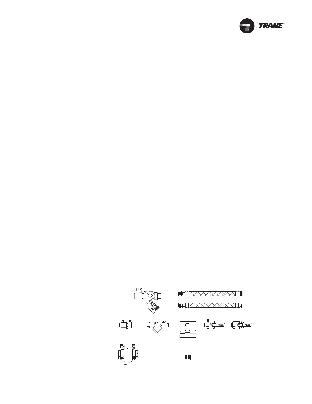
Model Number Description
312 3 4 1 * G P M N 0 R
1 2 3 4 5 6 7 8 9 10 11 12 13
Identifying and balancing a system is
simple throughTrane’s configurable hose
kit model number. Specific selections
include:
Digit 1: Hose KitType
4 = Standard Hose Kit
6 = Y-Body Hose Kit
3 = Standard Hose Kit with Isolation
Valve
5 = Y-Body Hose Kit with Isolation Valve
7 = Standard Hose Kit with Isolation
Valve (manual balancing)
8 = Standard Hose Kit (manual balancing)
Digit 2: Hose Kit Diameter
0 = 1/2" Diameter Hose
1 = 3/4" Diameter Hose
2 = 1" Diameter Hose
3 = 1-1/4" Diameter Hose
4 = 1-1/2" Diameter Hose
5 = 2" Diameter Hose
Digit 3: Hose Length
1 = 18" Stainless Steel Hose
2 = 24" Stainless Steel Hose
3 = 36" Stainless Steel Hose
Digit 4: Strainer Option
0 = No Strainer
3 = Strainer with Blow-Down Valve and
Hose Connector
Digit 5: Supply Ball Valve
4 = Supply Ball Valve with Pressure
Temperature Port
Digit 6: Return Ball Valve
1 = Return Ball Valve (no options)
4 = Return Ball Valve with Pressure
Temperature Port
Digit 7-10: Flow Control
A.AA = Ball Valve Hose Kit
0.00 Manual Flow Controls
0.50 GPM
1.00 GPM
1.50 GPM
2.00 GPM
2.50 GPM
3.00 GPM
3.50 GPM
4.00 GPM
4.50 GPM
5.00 GPM
6.00 GPM
7.00 GPM
8.00 GPM
9.00 GPM
10.0 GPM
12.0 GPM
14.0 GPM
16.0 GPM
18.0 GPM
20.0 GPM
25.0 GPM
30.0 GPM
35.0 GPM
40.0 GPM
45.0 GPM
50.0 GPM
55.0 GPM
60.0 GPM
Digit 11: Memory Stop Option
for Manual A.AA Hose Kit
N = No Memory Stop
7 = Memory Stop (for ball valve hose kit)
8 = Memory Stop (for manual circuit
setter)
Digit 12: Reducer Option
0 = No Reducer
R = Reducer to Decrease One Size
Digit 13: Isolation Valve Option
0 = No Isolation Valve
R = Isolation Valve
Digit 14-15: Manual Flow Control
00 = Auto flow control
AA = 0.23 Cv (1/2” hose)
BA = 0.46 Cv (1/2” hose)
CA = 0.55 Cv (3/4” hose)
DA = 0.87 Cv (1/2” hose)
EA = 1.1 Cv (3/4” hose)
FA = 1.8 Cv (1/2” hose)
GA = 2.2 Cv (3/4” hose)
HA = 2.3 Cv (1” hose)
JA = 3.3 Cv (1/2” hose)
KA=4Cv(3/4” hose)
LA = 5.4 Cv (1/2” hose)
MA = 5.4 Cv (1” hose)
NA = 5.5 Cv (1-1/4” hose)
PA = 6.7 Cv (3/4” hose)
RA = 9.2 Cv (1” hose)
SA = 9.8 Cv (1-1/4” hose)
TA = 13 Cv (2” hose)
UA = 14 Cv (1-1/2” hose)
VA = 19 Cv (1-1/2” hose)
WA = 20 Cv (1” hose)
XA = 20 Cv (1-1/4” hose)
YA = 24 Cv (1-1/4” hose)
ZA = 34 Cv (2” hose)
ZP = 56 Cv (2” hose)
PT
FLOW
YBall Strainer
with Blow Down Valve
and Hose Connector
Standard Valve
1/2” to 1 1/4” Dia.
Standard Valve
1-1/2” to 2” Dia.
Automatic Balancing Flow Control Valves
Y-Body Valve
1/2” to 1 1/4” Dia.
Stainless Steel Supply/Return Hoses
Isolation Valve
Step-Down Reducer
Ball Valve
with P/T Port
Return Ball Valve
No P/T Port
WSHP-PRC025D-EN 5
Page 6
Features and Benefits
Manual Flow Control
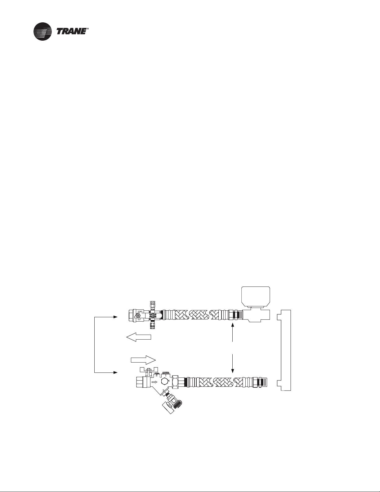
Ball Valve Flow Control
Traditionally, the first choice in a balancing device on a water-source heat pump application is the
lowest first cost option. In water-source heat pump fluid flow balancing, this typically employs a
manual balancing (ball valve) device with hoses. This method utilizes pressure/temperature (P/T)
measurement ports on the ball valves at the entering and leaving side of the heat pump so that
pressures and temperatures can be measured within the water piping.A ball valve is then manually
throttled to change the amount of flow to the unit to reach the desired temperature or pressure
differential.
Advantages
• Low first cost
• Direct access to the water-loop through P/T port for future trouble shooting
• Temperature and pressure measurements can cross check balancing
• Better water temperature measurement than external sensors
Disadvantages
• Flow accuracy of ±25%
• Eachunit must be balanced multiple times because of changing system conditions in balancing
other units
• Integral differential temperature balancing is less accurate than differential pressure balancing
• Pressure drop of hose and fittings must be accounted for in differential pressure measurements
Optional Isolation Valve
2-Position Valve
ISOLATION
VALVE
UNIT
Ball Valve
RETURN
SUPPLY
Optional Yball Strainer
w/Blowdown Valve &
Hose Connector
Mesurmeter w/PT’s
Flex Hose
PT
FLOW
Ball valve flow control hose kit is equipped with:
(2) Stainless Steel braided hoses with brass end fittings containing fiber washers.
(2) Bronze manual valves with brass ball with option P/T port on return side.
6 WSHP-PRC025D-EN
Page 7

Features and Benefits
(1) Optional electronic isolation valve for variable water volume control.
(1) Optional Y-ball strainer with brass cap and stainless steel mesh screen (includes blow down
valve and hose connector).
Table 1. Ball valve Cv factors
1/2" 3/4" 1" 1 1/4"
90-Degree (open) 15 30 43 48
80-Degree 9.3 17 28 54
70-Degree 5.0 9.0 16 31
60-Degree 2.9 5.1 9.2 20
50-Degree 1.8 2.9 5.8 12
40-Degree 1.0 1.5 3.1 6.3
30-Degree 0.4 0.7 1.6 3.2
20-Degree 0.1 0.1 0.4 0.8
10-Degree 0 0 0 0
0-Degree (closed) 0 0 0 0
Table 2. Strainer Cv factors
Strainer Size Cv
1/2” 5.1
3/4” 15
1” 27
1-1/4” 50
Note: Pressure drop information can be derived from the formula below:
DP:=Q2Sp
Cv
Q = flow in GPM
2
Sp = specific gravity
DP = pressure drop in PSI
Cv = flow coefficient
Circuit Setter Flow Control
Another choice in manual fluid flow balancing of a water-source heat pump includes a Hays
Measurmeter circuit setter flow control option.This manual balancing method uses an in-line flow
measurement device and an adjustment feature to measure and set flow rates at each heat pump.
Advantages
• In-line flow measurement device
• Easier to use than traditional or differential pressure/differential temperature methods
Disadvantages
• Flow accuracy of ±20%
• Higher pressure drop of circuit setters result in additional pumping energy costs (a 3/4-inch
circuit setter with 8-GPM flowing has 15-feet of pressure drop)
• Direct readout of flow rate is not possible with a circuit setter
• Eachunit must be balanced multiple times because of changing system conditions in balancing
other equipment
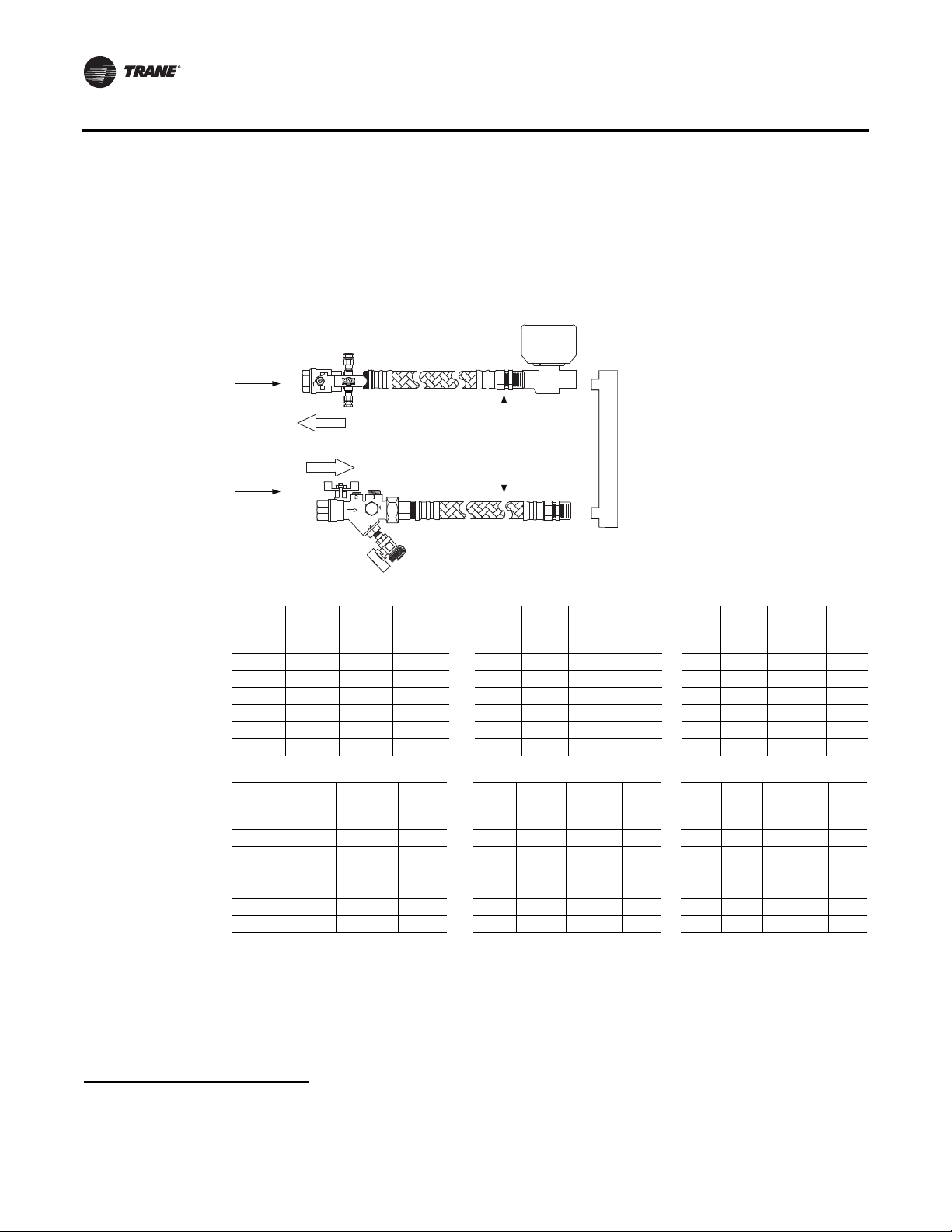
Circuit Setter flow control hose kit is equipped with:
(2) Stainless Steel braided hoses with brass end fittings containing fiber washers.
(1) Bronze manual valve (supply) with brass ball with option P/T port on return side.
WSHP-PRC025D-EN 7
Page 8
Features and Benefits
(1) Bronze manual valve includes memory stop positive shut-off and dual P/T ports.
(1) Optional electronic isolation valve for variable water volume control.
(1) Optional Y-ball strainer with brass cap and stainless steel mesh screen (includes blow down
valve and hose connector).
Ball Valve
RETURN
SUPPLY
Optional Yball Strainer
w/Blowdown Valve &
Hose Connector
FLOW
Mesurmeter w/PT’s
PT
Optional Isolation Valve
2-Position Valve
ISOLATION
VALVE
Flex Hose
UNIT
Size
1/2” 0.23 0.2-0.5 3/4” 0.55 0.4-1.2 1” 2.3 1.6-5.1
Value
0.46 0.3-1.0 1.1 0.8-2.5 5.4 3.8-12.1
0.87 0.6-1.9 2.2 1.6-4.9 9.2 6.5-20.6
1.8 1.3-4.0 4.0 2.8-8.9 20 14.1-44.7
3.3 2.3-7.4 6.7 4.7-15
5.4 3.8-12.1
Cv
Cv
Size
1-1¼” 5.5 3.9-12.3 1-½” 14 9.9-31.3 2” 13 9.2-29.1
Value
9.8 6.9-21.9 19 13.4-42.5 34 24.0-76.0
20 14.1-44.7 14 31.1-98.4 56 39.6-125.2
24 17.0-53.7
Automatic Flow Control
Automatic (Self) Balancing Flow Control
For automatic balancing of a water-source heat pump, the Hays™ self-balancing hose kit provides
a constant flow rate over the pressure differential range of 2 to 80 psid
Min-
Max
GPM* Qty Size
Min-Max
GPM* Qty Size
1
Cv
Value
Cv
Value
MinMax
GPM* Qty Size
Min-
Max
GPM* Qty Size
2
. As system pressures
Cv
Value
Cv
Value
Min-Max
GPM* Qty
Min-Max
GPM* Qty
1
For the latest Hayes Fluid Controls specification, please view the latest specification here:
http://flowcontrolvalves.haysfluidcontrols.com/category/automatic-balancing-valves
2
At low differential pressure the flow area required to achieve higher flow can exceed the flow area available for the respective series.
Therefore, the minimum pressure differential requirement is increased for the higher flow ranges of each series Mesurflo valve.
8 WSHP-PRC025D-EN
Page 9
Features and Benefits
change (through further addition of heat pumps, for example) each individual flow control valve
will automatically adjust to the new system conditions.
In variable water volume applications, there can be large variations in the system water pressure.
These pressure changes can adversely affect the system balance and heat pump operation. A self
balancing hose kit can provide continuous balancing in this application because of its ability to
automatically adjust to the varying system conditions.
Advantages
• Flow accuracy of ±10%
• Broader application in variable water volume pumping systems
• Greater flow accuracy results in operation closest to design, with least tenant complaints
• Only one pressure differential range of 2 to 80 psid
• Labor savings during balancing can offset increased material cost
• Same or less cost as manual balancing hose kits on smaller diameter hose kits
Disadvantages
• Greater first cost over other manual balancing methods
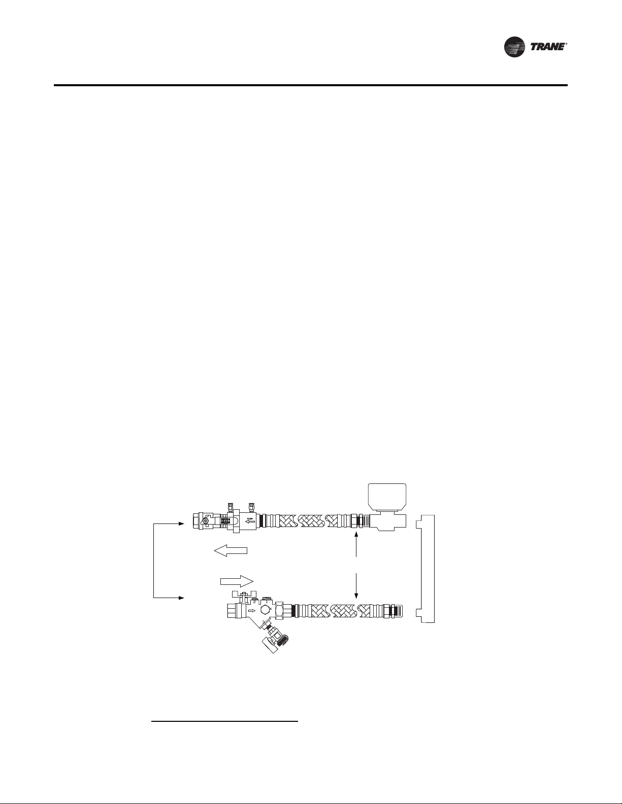
Automatic flow control hose kit is equipped with:
• Stainless Steel braided hoses with brass end fittings containing fiber washers
• Bronze manual shut-off valves with brass ball with P/T port on supply side
• Brass self-balancing valve
• Optional electronic isolation valve for variable water volume control
• BronzeY-ball strainer with brass cap and stainless steel mesh screen (includes a blow down
valve and hose connector).
1
Optional Isolation Valve
2-Position Valve
2510 Mesurflo w/PT’s
Ball Valve
RETURN
Flex Hose
SUPPLY
PT
FLOW
Optional Yball Strainer
w/Blowdown Valve &
Hose Connector
1
At low differential pressure the flow area required to achieve higher flow can exceed the flow area available for the respective series.
Therefore, the minimum pressure differential requirement is increased for the higher flow ranges of each series Mesurflo valve.
ISOLATION
VALVE
UNIT
WSHP-PRC025D-EN 9
Page 10
Features and Benefits
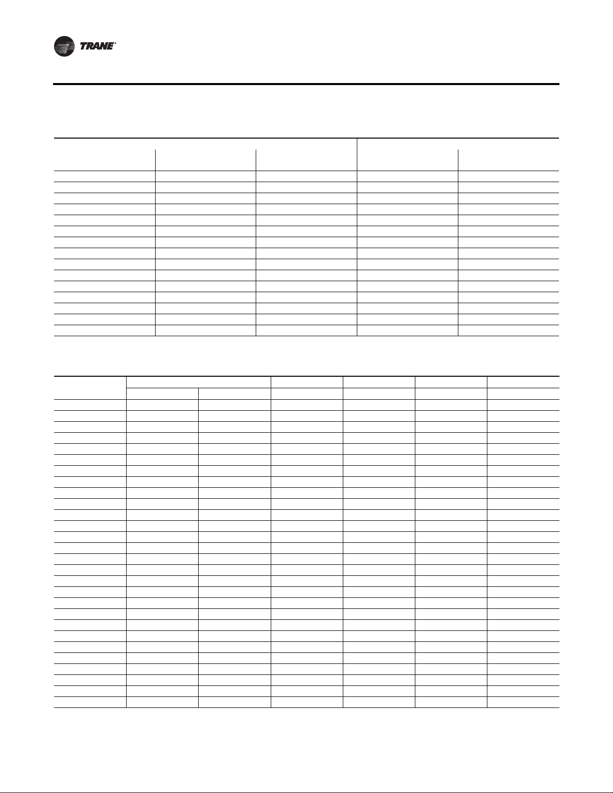
Table 3. Hose kit selection vs. heat pump tonnage
Closed Loop Applications Closed Loop Applications (50-55°F)
Tonnage (Tons)
3/4 2.25 1/2 1.0 1/2
1 3.0 1/2 1.5 1/2
1¼ 3.5 1/2 2.0 1/2
1½ 4.5 1/2 2.0 1/2
2 6.0 3/4 2.5 1/2
2½ 7.0 3/4 3.5 1/2
3 8.0 3/4 4.0 1/2
3½ 10 1 4.5 1/2
4 12 1 5.0 3/4
5 14 1¼ 7.0 3/4
6 18 1¼ 8.0 3/4
7 20 1¼ 9.0 1
10 28 1½ 14 1¼
15 42 2 29 1¼
20 56 2 30 1½
Note: Consult Heat Pump Manufacture for other temperature applications.
Flow
(GPM)
Pipe
Size (in)
Flow
(GPM)
Pipe
Size (in)
Table 4. Kit w/ATC, 1 ball valve,Y-ball strainer & Measurflo automatic flow control valve, 24” hose
Flow Rate
0.5 2.08 2.02
1 2.34 2.09 2.04
1.5 2.76 2.2 2.10 2.01 2.01
2 3.34 2.35 2.18 2.01 2.01
2.5 4.01 2.54 2.28 2.02 2.01
3 5.02 2.78 2.4 2.03 2.02
3.5 6.12 3.06 2.55 2.04 2.03
4 7.37 3.39 2.72 2.05 2.04
4.5 8.8 3.76 2.91 2.07 2.05
5 10.4 4.17 3.12 2.08 2.06
6 15.09 6.12 4.62 3.12 3.08
7 21.46 9.25 7.2 3.16 3.11
8 26.5 10.55 7.88 3.21 3.15
9 12.03 8.64 3.27 3.19
10 11.68 7.49 3.33 3.23
12 15.49 9.47 3.48 3.33
14 20.01 11.81 3.65 3.45
16 25.21 14.51 3.86 3.59
18 31.11 17.56 4.08 3.74
20 37.71 20.97 4.34 3.92
25 57.23 31.08 5.09 4.43
30 44.44 7.01 6.06
35 59.04 8.09 6.81
40 75.89 9.34 7.67
45 94.99 10.76 8.64
50 116.33 12.35 9.73
55 14.1 10.93
60 16.02 12.25
Size (in) 1/2 3/4 1 1¼ 1½
Cv 3.5 4.7 6.5 41.1 41.3
10 WSHP-PRC025D-EN
Page 11

Features and Benefits
Table 5. Kit, 1 ball valve,Y-ball strainer & Measurflo automatic flow control valve, 24” hose
Flow Rate Size (in) 1/2 3/4 1 1¼ 1½
0.5 2.06 2.01
1 2.25 2.04 2.02
1.5 2.57 2.09 2.05 2.01
2 3.02 2.17 2.09 2.01 2.01
2.5 3.59 2.26 2.13 2.02 2.01
3 4.29 2.37 2.19 2.02 2.02
3.5 5.12 2.51 2.26 2.03 2.02
4 6.07 2.66 2.34 2.04 2.03
4.5 7.15 2.84 2.43 2.06 2.03
5 8.36 3.04 2.53 2.07 2.04
6 12.15 4.49 3.77 3.1 3.06
7 17.46 7.03 6.04 3.13 3.11
8 21.27 7.66 6.36 3.18 3.11
9 8.36 6.72 3.22 3.14
10 7.15 11.9 3.27 3.17
12 8.98 6.06 3.4 3.25
14 11.13 7.17 3.54 3.33
16 13.62 8.44 3.7 3.44
18 16.45 9.89 3.89 3.55
20 19.6 11.5 4.1 3.68
25 16.29 4.72 4.07
30 23.14 6.47 5.54
35 30.05 7.37 6.09
40 38.02 8.4 6.73
45 47.06 9.56 7.45
50 50.0 10.87 8.26
55 12.31 9.16
60 13.89 10.14
Self-Balancing Hose Kits
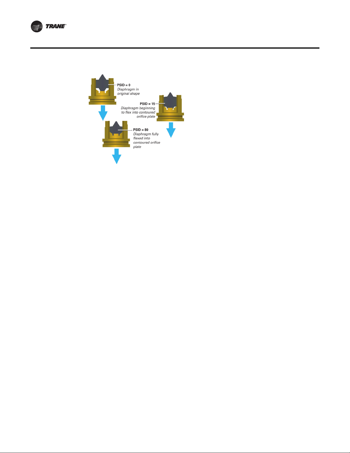
The Hays self balancing valve contains a rubber diaphragm that is designed to flex into a contoured
orifice plate. This allows the valve to decrease the water flow path as pressure increases. The
pressure differential ranges of a Hays automatic valve covers 2 to 80 psid
diaphragm against the fixed orifice plate makes the Hay’s valve difficult to clog and resistant to
cavitation damage. Outside of the pressure differential window, the controller continues to
perform as high as 150 psid, but does not become a fixed orifice.
Note: The Hays self balancing valve is a constant flow rate device that contains a variable orifice
to govern water flow. Since it is a variable orifice, it can not be described with a Cv or a
pressure drop at a given flow for piping system design purposes. Conversely, the designer
may assume a constant flow rate over the pressure differential range of 2 to 80 psid
uses constant pressure in system design.
1
At low differential pressure the flow area required to achieve higher flow can exceed the flow area available for the respective series.
Therefore, the minimum pressure differential requirement is increased for the higher flow ranges of each series Mesurflo valve.
WSHP-PRC025D-EN 11
1
.The flexing of the rubber
1
as one
Page 12
Features and Benefits
There are three features that every self-balancing valve should possess to accomplish the job of
automatically balancing an HVAC system in the industry.The valve should be:
• Non Clogging
• Quiet
• Accurate
Non-Clogging. The live flexing action of the elastomeric diaphragm against the orifice seat
permits passage of reasonably sized particles of sludge, rust balls, thread chips, and other debris.
Because the working parts are of a two piece design, they are resistant to fouling. Back pressure
forces the diaphragm away from the orifice seat allowing any debris to be back-flushed away. Hays
is the only balancing valve that provides unrestricted flow during back flush.
Quiet. By design, the Hays automatic balancing valve is inherently quiet. The only moving part
is an elastomeric polymer diaphragm in an orifice seat that is made from polyphenylsulfone.
Together, these materials have a natural sound deadening ability.The Hays valve neither clicks nor
is noisy, and has only one control range.
Accurate. What does accurate mean? Is it the stable, predictable delivery of thermal energy in a
hydronic system?The Hays valve is accurate ±10%, that equates to 99.8% heat transfer. Because
the polymer diaphragm compensates for changes in fluid temperature the valve provides stable
thermal system performance. The addition of antifreeze to the fluid further increases the need for
the offsetting characteristics of the Hays automatic valve.
Hose Kit Specifications
Ball Valve Flow Control
Each kit contains two manual flow control ball valves, two flexible hoses, and may include a high
flowY-ball strainer and various other accessories.
Flow Control
Each kit contains two manual ball valves, one Hays Measurmeter (with Venturi Cv insert) two
flexible hoses, and may include a high flow Y-strainer and various other accessories.
The circuit setter valve body and ball valve are constructed from brass. It contains a maximum
working pressure of 400 psi with a maximum flow temperature of 40-200°F (operating temperature
range) and a minimum flow temperature of 15°F (-10°C).
Automatic Flow Control
Each kit contains a Hays Mesurflo® automatic flow control valve, two ball valves, two flexible
hoses, a high flowY-ball strainer, and includes a blow-down and various other accessories.
12 WSHP-PRC025D-EN
Page 13

Features and Benefits
The automatic flow control valve is factory set to a rated flow, and shall automatically control the
flow to within 10% of the rated value over a 40 to 1 differential pressure, operating range (2 to 80
1
psid
). Operational temperature is rated 40-200°F.The valve body is constructed from hot forged
brass UNS C37700 per ASTM B-283 latest revision.
The ball valve is constructed from forged bronze with brass ball construction. It is rated from fluid
40-200°F. Valve bodies are suitable for 400 PSIG, with a working pressure rating per ASTM A53B
threaded joint type. A pressure/temperature test port is provided for verifying the pressure
differential and system temperature.
All supply and return hoses are equipped with swivel end connections. All end connections are
permanently crimped to meet state pressure ratings.
1/2-inch to 1 1/4-inch hose material is EPDM rubber, and rated for maximum working pressure of
400 PSI (1/2-inch), 400 PSI (3/4 to 1 1/4-inch), 400 PSI (1 1/2 and 2-inch).Theminimum burst pressure
is four times the working pressure.
Hose material is stainless steel braid over an EPDM liner, and bonded to the braid. Hoses are rated
for 40-225°F.
Hose connectors are permanently crimped. Swivels shall be BP with a male NPT.Adapters are fixed
male NPT. All connections are brass and have reusable thread sealant pre-applied to the tapered
pipe threads.
1½” and larger hose materials are a single stainless steel braid over a corrugated type 321 stainless
steel tube, butt welded to carbon steel end fittings. Operational temperature are rated from 25°F225°F.
Hoses are rated for a minimum working pressure of 400 PSI (1½”), 400 PSI (2”). Minimum burst
pressure is four time the working pressure.
TheY-ball strainer body is constructed of bronze with a brass cap. The cap is sealed with a non
asbestos gasket.The strainer body is suitable for 400 PSIG, with a maximum pressure rating of 400,
at 150°F WOG. Working pressure rating is Class 125.The strainer screen is 304 stainless steel with
20-mesh (½”-1¼”). The strainer is ported with female pipe thread per ASME/ANSI b1.20.1, and
B31.9.
The motorized water valve is a 2-position, spring-return water valve installed on the return side of
the system. The valve will open when the unit compressor begins running to allow water flow
through the unit. As the compressor shuts down, the valve will slowly close off water through the
unit to reduce water consumption.
1
At low differential pressure the flow area required to achieve higher flow can exceed the flow area available for the respective series.
Therefore, the minimum pressure differential requirement is increased for the higher flow ranges of each series Mesurflo valve.
WSHP-PRC025D-EN 13
Page 14

Page 15

Page 16

Trane optimizes the performance of homes and buildings around the world. A business of Ingersoll Rand, the leader in
creating and sustaining safe, comfortable and energy efficient environments, Trane offers a broad portfolio of advanced
controls and HVAC systems, comprehensive building services, and parts. For more information, visit www.Trane.com.
Trane has a policy of continuous product and product data improvement and reserves the right to change design and specifications without notice.
© 2015Trane All rights reserved
WSHP-PRC025D-EN 07 Jan 2015
Supersedes WSHP-PRC025C-EN (12 Sep 2014)
We are committed to using environmentally
conscious print practices that reduce waste.
 Loading...