

Page 1
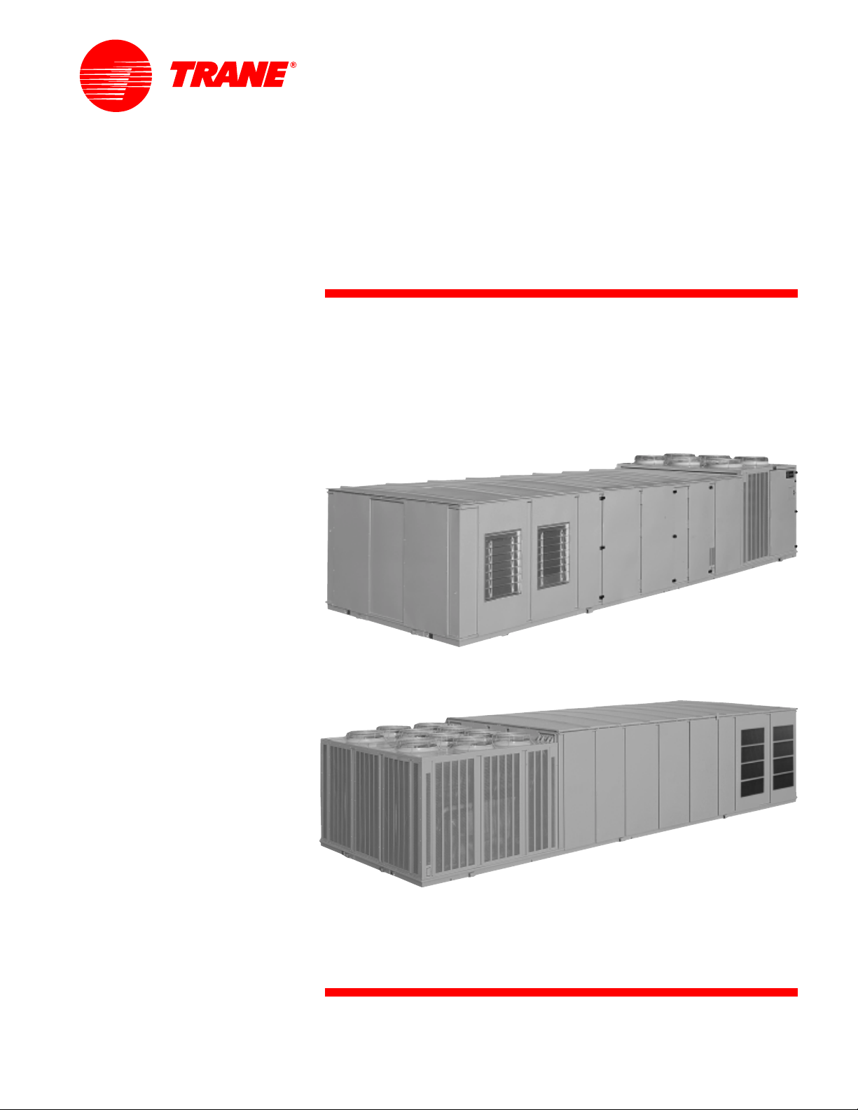
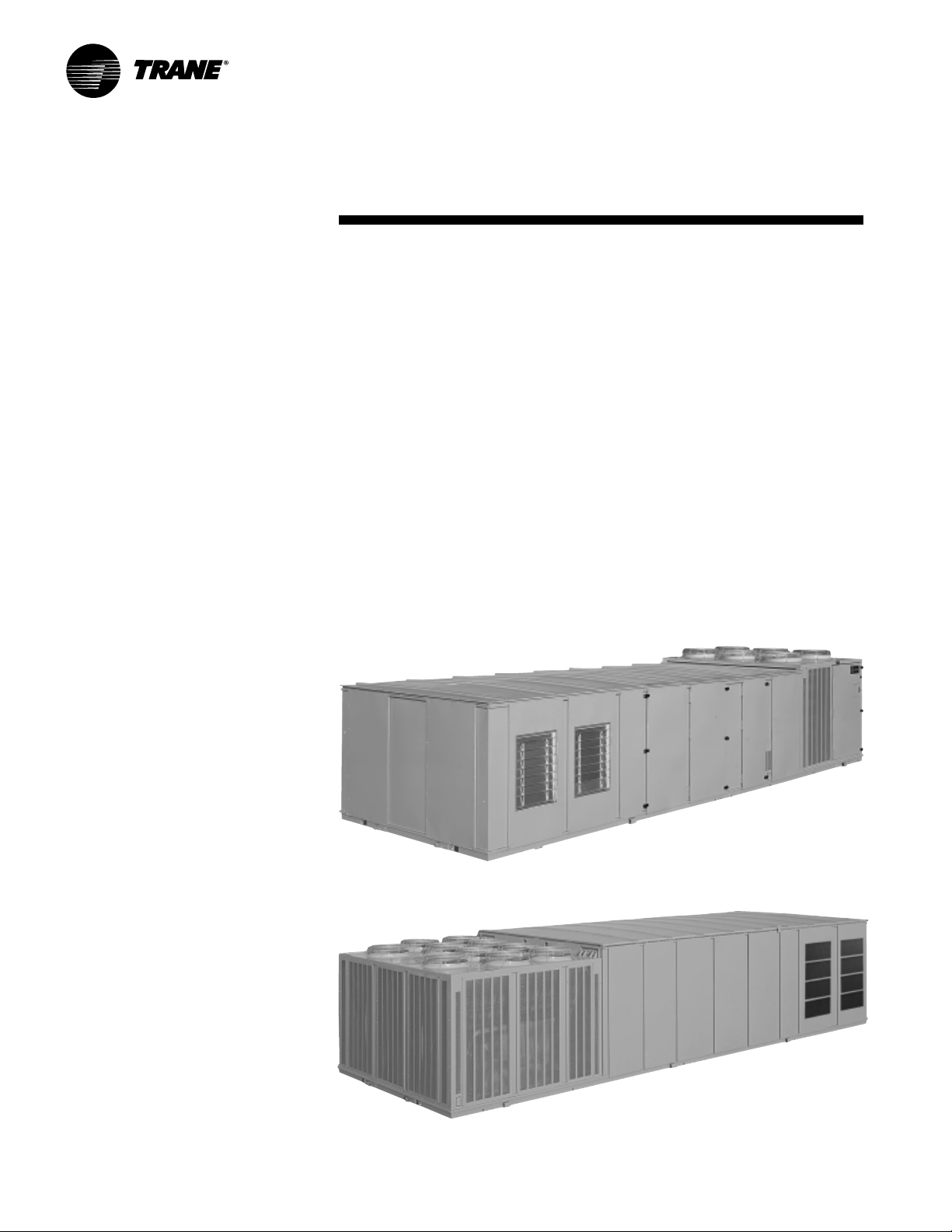
Packaged Rooftop
Air Conditioners
IntelliPak™ Rooftops
20 - 130 Tons — 60 Hz
20 - 75 Tons
90 - 130 Tons
March 2003
RT-PRC010-EN
Page 2
Introduction
IntelliPak
™
Designed For Today and Beyond
Innovative technology and an
impressive lineup of features make the
Trane IntelliPak Rooftop line the number
one choice for today and the future.
Trane’s rooftop Unit Control Module
(UCM), an innovative, modular
microprocessor control design,
coordinates the actions of the IntelliPak
rooftop in an efficient manner and allows
for stand-alone operation of the unit.
Access to the unit controls, via a Human
Interface Panel, provides a high degree
of control, superior monitoring
capability, and unmatched diagnostic
information.
Optionally, for centralized building
control on-site, or from a remote
location, IntelliPak can be configured for
direct communication with a Trane
Tracer™ building management system
rd
party LonTalk building
or a 3
management system, using a twisted
pair of wires. With one of these systems,
the IntelliPak status data and control
adjustment features can be conveniently
monitored from a central location.
IntelliPak has the technology
flexibility
every building space.
to bring total comfort to
and
© 2003 American Standard Inc. All rights reserved
RT-PRC010-EN
Page 3

Contents
Introduction
Featur es and Benefits
Application Considerations
Selection Procedur e
Model Number Description
General Data
P erformance Data
Performance Adjustment Factors
Controls
Electric P o wer
Dimension and W eights
Mechanical Specifications
Options
2
4
9
16
20
22
29
28
75
83
86
99
96
RT-PRC010-EN
3
Page 4

Features and
Benefits
Standard Features
• 20 to 130 ton industrial/ commercial
rooftops
• Fully integrated, factory-installed/
commissioned microelectronic
controls
• Unit mounted Human Interface Panel
with a 2 line x 40 character English
display and a 16 function keypad that
includes Custom, Diagnostics, and
Service Test mode menu keys.
• Trane 3-D
(20 to 130 Tons)
• Compressor or circuit lead/lag
depending on unit
• Hinged access doors on control panel,
filter section, and gas heat section
• Horizontal discharge/return duct
connections (SX, SL, SS models)
• CV or VAV control
• Low ambient compressor lockout
control on units with economizers
• Frostat™ coil frost protection on
all units
• Daytime Warm-up (Occupied mode)
on VAV models and Morning Warm-up
operation on all units with heating
options
• Supply air static overpressurization
protection on units with inlet guide
vanes and VFD’s.
• Supply airflow proofing
• Exhaust airflow proofing on units with
exhaust option
• Supply air tempering control
• Supply air heating control on VAV
modulating hot water or steam heat
units
• Emergency stop input
• Liquid and Discharge Service Valves
• Mappable sensors and setpoint
sources
• Occupied/Unoccupied switching
• Timed override activation
• Forward-curved supply fans (20 - 75
ton models)
• Air foil supply fans (90 - 130 ton
models)
• Pitched roof over air handler section
• Stainless steel flue stack on gas heat
units
• 14-gauge, single-piece construction
base rails
™
Scroll compressors
• UL and CSA approval on standard
options
• Two-inch spring fan isolation
(90 to 130 tons)
• Meets 672 hours of salt spray testing in
accordance to ASTM B117 Standard
• Two inch standard efficiency
throwaway filters on 20 to 90 ton units
and two inch high efficiency
throwaway filters on 105 to 130 ton
units.
Optional Features
For a comprehensive listing of standard
options, special options, and
accessories, please see table O-1 starting
on page 96.
• Trane Communication Interface
Module: ICS interface control module
®
• LonTalk
module
• Remote Human Interface Panel
(controls up to 4 units)
• Five ventilation override sequences
• Heating options: natural gas, electric,
hot water or steam
• Generic BAS interface
• Choose from three economizer control
options: comparative enthalpy,
reference enthalpy, dry bulb control
• Variable frequency drive control of
supply/exhaust fan motor
• Inlet guide vanes on FC supply fans
(VAV only)
• Outside air CFM compensation on VAV
units with IGV (or VFD) and economizer
• Hot gas bypass to the evaporator inlet
• Copper evaporator/condenser coils
• Suction service valves
• Replaceable core filter driers
• Phenolic coated evaporator/condenser
coils
• High capacity evaporator coils
(20 to 105 tons)
• Special paint colors
• Extended casing (SX models)
• Double wall access doors
• Double wall construction/perforated
double wall
• Stainless steel drain pan in evaporator
section
• Pitched evaporator drain pan
Communication Interface
• Filter rack only (no filters)
• High efficiency throwaway filters
• 90-95 percent bag filters
• 90-95 percent cartridge filters
• Final filters
• Barometric relief
• 50 percent modulating exhaust with
forward-curved fans
• Trane’s air quality (Traq™) sensor
• Modulating Gas Heat
• 10 year limited warranty on Full
Modulation Gas Heat
• 100 percent modulating exhaust with
forward-curved fans
• 100 percent modulating exhaust with
FC fans and Statitrac™ direct space
sensing building pressurization control
• High duct temperature thermostats
• 0 F low ambient control
• 0-100 percent modulating fresh air
economizer
• Ultra low leak dampers for 0-100
percent modulating fresh air
economizers
• Dual electrical power connection
• Two-inch spring fan isolation
(20 to 75 tons)
• High efficiency motors
• U-frame motors
• Oversized motors
• Through the door non-fused
disconnect with external handle
• Electrical convenience outlet
• Power supply monitoring
• Correction capacitors
• Horizontal or Roof discharge w/gas
heat (20-75 tons “F” style units only)
Field Installed Accessories
• Roof curbs
• Programmable sensors with night set
back — CV and VAV
• Sensors without night set back — CV
and VAV
• Remote zone sensors — used for
remote sensing with remote panels.
• ICS zone sensors used with Tracer™
system for zone control
• Outdoor temperature sensor for units
without economizers
• Remote minimum position control for
economizer
• Field installed module kits available for
field upgrade of controls
Note: LonTalk and LonWorks are registered trademarks of Echelon Corporation.
RT-PRC010-EN4
Page 5

Features and
Benefits
Features Summary
IntelliPak™ rooftop features make
installation and servicing easy and
reliable operation a reality.
Installation Ease
• Factory-installed/commissioned
controls
—ease of start up
—single twisted wire pair
—communication for ICS interface
—full unit points access, no field wir-
ing of required points
• Unit mounted Human Interface Panel
standard
—user friendly keypad — edit
parameters
— through the access door interface
— start up adjustments
— unit mounted and remote in-
terface panel key pads are
identical
• Unit mounted lifting lugs facilitate
installation and can be used as unit
tiedown points.
Easy to Service
• The microprocessor unit controls
coordinates the operation of the
rooftop with quality, industry-accepted
components for service ease.
• Unit mounted Human Interface Panel
standard
— user friendly keypad — edit pa-
rameters
— through the access door interface
— start up adjustments
— unit mounted and remote interface
panel key pads are identical
• Modularity of unit control design
—individual replaceable functional
boards
• Advanced diagnostics
Reliability
• Advanced diagnostics
• Microprocessor controls
• Built-in safeties
• Modular control design
• UL approval as standard
• Forward-curved supply and exhaust
fans are Trane designed and factory
balanced.
• Fully insulated and gasketed panels
reduce ambient air infiltration.
• Fixed-speed evaporator fan and
exhaust drive for smooth fan operation
and belt durability.
• 200,000 average life fan bearings
enhance unit durability.
• Gas heater with free-floating stainless
steel heat exchanger relieves the
stresses of expansion and contraction.
Stainless steel provides corrosion
resistance through the entire material
thickness.
• Integral condenser subcooler improves
efficiency while helping avoid liquid
flashing.
• Factory-wired and commissioned
controls assure efficient and reliable
rooftop operation.
• Trane Scroll compressors are used on
20 to 130 ton units. They are designed
for tough industrial operation and
meet demanding operating conditions
both in efficiency and reliability.
• Roll-formed construction enhances
cabinet integrity and assures a
leakproof casing.
• Three-phase, direct-drive condenser
fan motors enhance dependability and
increase rooftop life.
• Trane industrial quality evaporator
and condensing coils help increase
rooftop life.
Application Flexibility
• Modularity in design
• Increased offering of standard options
• Generic BAS interface
• Five factory preset/re-definable in the
field ventilation override sequences
• Superior Tracer™ interface for ICS
applications
— factory-installed Trane
• Superior LonTalk interface for Tracer
and 3rd party applications
— factory-installed LonTalk
Communication Interface
• Unit mounted or Remote Human
Interface panels
— all parameter are editable from the
Human Interface Panel
• Comparative enthalpy, Reference
enthalpy, or Dry bulb control for
economizers
• Statitrac™ direct space building
pressure control
• Compensated outdoor air control —
IAQ
• Factory-installed filter rack includes
two-inch throwaway filters.
• CV controls stage both compressors
and heat based on space
requirements.
• Variable Frequency Drives (VFD)
Included With or Without Bypass
Control for Supply and Exhaust Fans.
• An array of heating options are
available, including Steam, Hot Water,
Electric and Natural Gas heat. The Gas
Heating option provides a choice of
two-stage gas heat, as well as full and
limited modulating gas heat.
5RT-PRC010-EN
Page 6
Integrated
Rooftop
Systems:
Profitable,
Simple
Trane integrated rooftop systems make
design and installation of building
management systems cost effective and
easy. Trane offers two choices for
building management controls: Tracer
Building Automation System with a
Trane Control Interface (TCI) or Tracer
with LonTalk® Communication Interface
(LCI).
Integrated
Comfort with
Trane Tracer™
TCI
The Tracer TCI Integrated Comfort™
System (ICS) improves job profit and
increases job control by combining Trane
rooftop units with the Trane Tracer
building management system. This
integrated system provides total building
comfort and control. Some of the
primary motivations for building
owners/managers in deciding to
purchase a HVAC controls system is
energy savings, cost control, and the
convenience of facility automation.
Simplifying the Comfort System
Trane’s technology and innovation brings
more capabilities, more flexibility, and at
the same time, offers equipment and
systems that are easy to use, easy to
install, commission, and service. The
Tracer TCI Integrated Comfort system
saves time and money by simplifying
system design and system installation.
When used with Trane’s DDC/VAV boxes
(or VariTrane™), system balancing
almost goes away because each VAV box
is commission and tested before it
leaves the factory. All the status
information and editing data from the
Features and
Benefits
rooftop units, VAV boxes, lighting,
exhaust and other auxiliary equipment is
available from Tracer TCI for control,
monitoring and service support of your
facility. Tracer, a family of building
automation products from Trane, is
designed with robust, application
specific software packages to minimize
custom programming requirements and
enable system setup and control
through simple editing of parameters in
the standard applications software.
Should you select an Integrated Comfort
system for your facility, the
accountability for equipment,
automation and controls is Trane’s,
Trane’s, and Trane’s!
The IntelliPak
Integrated Comfort system, provides
powerful maintenance monitoring,
control and reporting capabilities. The
Tracer places the rooftop in the
appropriate operating mode for
operation for: system on/off, night
setback, demand limiting , setpoint
adjustment based on outside
parameters and much more. Up to 56
different unit diagnostic conditions can
be monitored through Tracer to let you
know about things like: sensor failures,
loss of supply airflow, and a compressor
trip out. Further, the addition of Building
Management Network software offers
remote scanning, automatic receipt of
alarms, and easy dial-up access to over
100 various Tracer sites across town or
across the country.
Typical points available through Tracer:
IntelliPak Rooftops monitoring points
available through Tracer
• all active Rooftop diagnostics
• history of last 20 unit diagnostics
• all system setpoints
• system sensor inputs
• supply fan mode and status
• inlet guide vane position/VFD speed
• unit heat/cool mode
• exhaust fan status
• exhaust damper position
• economizer position, minimum
position setpoint, economizing
setpoint
• on/off status of each compressor
• refrigerant evaporator and saturated
condenser temperatures
• hydronic heat valve position
rooftop, as a part of an
• electric heat stage status
• ventilation override mode status
Tracer control points for IntelliPak
Rooftops
• cooling and heating setpoints
• zone setpoint offsets for use with
demand limiting
• VAV discharge air setpoints
• supply air pressure setpoint
• space pressure setpoint
• zone and outdoor temperature values
• cooling and heating enable/disable
• economizer enable/disable
• economizer setpoint
• economizer minimum position
• activation of ventilation override
modes
• diagnostics reset
• unit priority shutdown
IntelliPak Rooftops setup and
configuration information through Tracer
• supply fan mode
• configuration of supply air reset
• ventilation override mode
configuration
• default system setpoint values
• sensor calibration offsets
Interoperability
with LonTalk
The Trane Tracer LonTalk Control
Interface (LCI) for IntelliPak offers a
building automation control system with
outstanding interoperability benefits.
LonTalk, which is an industry standard, is
an open, secure and reliable network
communication protocol for controls,
created by Echelon Corporation and
adopted by the LonMark Interoperability
Association. It has been adopted by
several standards, such as: EIA-709.1, the
RT-PRC010-EN6
Page 7

Features and
Benefits
Electronic Industries Alliance (EIA)
Control Network Protocol Specification
and ANSI/ASHRAE 135, part of the
American Society of Heating,
Refrigeration, and Air-Conditioning
Engineer’s BACnet control standard for
buildings.
Interoperability allows application or
project engineers to specify the best
products of a given type, rather than one
individual supplier’s entire system. It
reduces product training and installation
costs by standardizing communications
across products. Interoperable systems
allow building managers to monitor and
control IntelliPak equipment with a Trane
Tracer Summit or a 3
automation system. It enables
integration with many different building
controls such as access/intrusion
monitoring, lighting, fire and smoke
devices, energy management, and a
wide variety of sensors (temperature,
pressure, light, humidity, occupancy,
CO2 and air velocity). For more
information on LonMark, visit
www.lonmark.org or Echelon,
www.echelon.com.
rd
party building
Optimum
Building
Comfort Control
The modular control design of the UCM
allows for greater application flexibility.
Customers can order exactly the options
required for the job, rather than one
large control package. Unit features are
distributed among multiple field
replaceable printed circuit boards. The
Trane UCM can be set up to operate
under one of three control applications:
1 stand-alone
2 interface with Trane’s Tracer™ building
management system
3 interface with a generic (non-Trane)
building management system. All
setup parameters are preset from the
factory, requiring less start-up time
during installation.
The unit mounted Human Interface and
the Remote Human Interface Panels’
functions are identical, except for the
Service mode is not available on the
Remote Human Interface Panel. This
common interface feature requires less
time for building maintenance personnel
to learn to interact with the unit. All of the
rooftop’s control parameters are
adjustable and can be set up through the
Remote Human Interface Panel such as,
but not limited to: system on/off,
demand limiting type, night setback
setpoints, and many other setpoints. No
potentiometers are required for setpoint
adjustment, all adjustments are done
through the Remote Human Interface
keypad. Also up to 56 different rooftop
diagnostic points can be monitored
through the human interfaces such as:
sensor failures, loss of supply airflow,
and compressor trip. No special tools are
required for servicing of the unit. All
diagnostic displays are available in clear
English at the Remote Human Interface
and will be held in memory, so that the
operator/servicer can diagnose the root
cause of failures.
Statitrac™ Direct Space
Building Pressurization Control
Trane’s Statitrac™ control is a highly
accurate and efficient method of
maintaining building pressure control
with a large rooftop air conditioner.
The efficiency is achieved with a 100
percent modulating exhaust system with
two forward-curved fans with
modulating discharge dampers that
operate only when needed, compared to
some systems that operate continually.
And most of the operating hours of the
100 percent modulating exhaust system
are at part load, saving more energy.
Trane’s Statitrac, with the 100 percent
modulating exhaust system, provides
comfort and economy for buildings with
large rooftop air conditioning systems.
Statitrac control is simple! The space
pressure control turns the exhaust fans
on and off as required and modulates
exhaust dampers to maintain space
pressure within the space pressure dead
band. Using the unit mounted Human
Interface Panel you can
1) adjust space pressure setpoint
2) adjust space pressure dead band
3) measure and read building space
pressure. The modulating exhaust
system maintains the desired building
pressure, saving energy while keeping
the building at the right pressure. Proper
building pressurization eliminates
annoying door whistling, doors standing
open, and odors from other zones.
The Statitrac™ direct space building
control sequence will be maintained
when a variable frequency drive is used.
Fans With Inlet Guide Vanes
Trane’s forward curved fans (20 through
75 tons) and air foil fans (90 through 130
tons) with inlet guide vanes pre-rotate
the air in the direction of the fan wheel,
decreasing static pressure and
horsepower, essentially unloading the
fan wheel. The unloading characteristics
result in superior part load performance.
Variable Frequency Drives
(VFD)
Variable Frequency Drives are factory
installed and tested to provide supply/
exhaust fan motor speed modulation.
VFD’s, as compared to inlet guide vanes
or discharge dampers, are quieter, more
efficient, and are eligible for utility
rebates. The VFD’s are available with or
without a bypass option. Bypass control
will simply provide full nominal airflow
in the event of drive failure.
7RT-PRC010-EN
Page 8

Features and
Benefits
Trane 3-D™ Scroll Compr essor
Simple Design with 70% Fewer Par ts
Fewer parts than an equal capacity
reciprocating compressor means
significant reliability and efficiency
benefits. The single orbiting scroll
eliminates the need for pistons,
connecting rods, wrist pins and valves.
Fewer parts lead to increased reliability .
Fewer moving parts, less rotating mass
and less internal friction means greater
efficiency than reciprocating
compressors.
The Trane 3-D S croll provides impor tant
reliability and efficiency benefits. The 3-D
Scroll allows the orbiting scrolls to touch
in all three dimensions, forming a
completely enclosed compression
chamber whic h leads to increased
efficiency . In addition, the orbiting scrolls
only touch with enough force to create a
seal; there is no wear between the scroll
plates. The fixed and orbiting scrolls are
made of high strength cast iron which
results in less thermal distortion, less
leakage, and higher efficiencies. The
most outstanding feature of the 3-D
Scroll compressor is that slugging will
not cause failure. In a reciprocating
compressor, however , the liquid or dir t
can cause serious damage.
Low T orque Variation
The 3-D Scroll compressor has a very
smooth compression cycle; torque
variations are only 30 percent of that
produced by a reciprocating compressor.
This means that the scroll compressor
imposes very little stress on the motor
resulting in greater reliability. Low torque
variation reduces noise and vibration.
Suction Gas Cooled Motor
Compressor motor efficiency and
reliability is further optimized with the
latest scroll design. Cool suction gas
keeps the motor cooler for longer life and
better efficiency.
Proven Design Through T esting and
Research
With over twenty years of development
and testing, Trane 3-D S croll
compressors have undergone more
than 400,000 hours of laboratory testing
and field operation. This work combined
with over 25 patents makes Trane the
worldwide leader in air conditioning
scroll compressor technology .
One of two matched scroll plates — the
distinguishing feature of the scroll
compressor.
Chart illustrates low torque variation of
3-D Scroll compressor vs reciprocating
compressor.
RT-PRC010-EN8
Page 9

Application
Considerations
EXHAUST AIR OPTIONS
When is it necessary to provide building
exhaust? Whenever an outdoor air
economizer is used, a building generally
requires an exhaust system. The purpose
of the exhaust system is to exhaust the
proper amount of air to prevent over or
underpressurization of the building. The
goal is to exhaust approximately 10
percent less air than the amount of
outside air going into the building. This
maintains a slightly positive building
pressure.
A building may have all or part of its
exhaust system in the rooftop unit. Often,
a building provides exhaust external to
the air conditioning equipment. This
external exhaust must be considered
when selecting the rooftop exhaust
system.
IntelliPak™ Rooftop units offer four types
of exhaust systems:
1
100 percent modulating exhaust with
Statitrac™ direct space sensing building
pressurization control (with or without
variable frequency drives).
2
100 percent modulating exhaust without
Statitrac.
3
50 percent power exhaust.
4
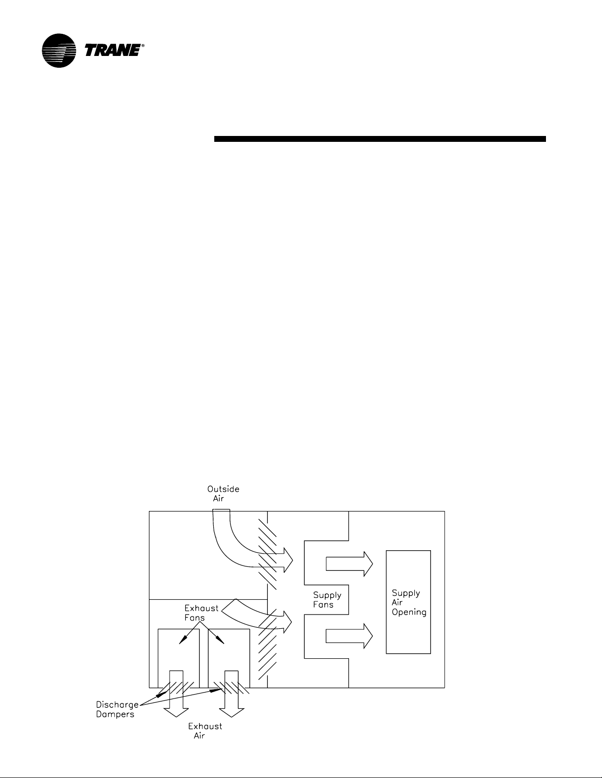
Barometric relief dampers.
Application Recommendations
1
100 per cent modulating exhaust with
Statitrac™ contr ol
For both CV and VAV rooftops, the 1 00
percent modulating exhaust discharge
dampers (or VFD) are modulated in
response to building pressure. A
differential pressure control system,
called Statitrac™, uses a dif ferential
pressure transducer to compare indoor
building pressure to atmospheric
pressure. The FC exhaust fan is turned on
when required to lower building static
pressure to setpoint. The Statitrac control
system then modulates the discharge
dampers (or VFD) to control the building
pressure to within the adjustable,
specified dead band that is set at the
Human Interface Panel.
Advantag es of the Statitrac™
100 per cent modulating exhaust
system are:
a
The exhaust fan runs only when needed
to lower building static pressure.
b
Statitrac compensates for pressure
variations within the building from
remote exhaust fans and makeup
air units.
c
The exhaust fan discharges in a single
direction resulting in more efficient fan
operation compared to return fan
systems.
d
Because discharge dampers modulate
the airflow, the exhaust fan may be
running unloaded whenever the
economizer dampers are less than 100
percent open.
With an exhaust fan system, the supply
fan must be sized to pull the return air
back to the unit through the return
system during non-economizer
operation. However, a supply fan can
typically overcome return duct losses
more efficiently than a return air fan
system. Essentially, one large fan by itself
is normally more efficient than two fans
in series because of only one drive loss
not two as with return air systems.
The reason for either a return air fan or
an exhaust fan is to control building
pressure. The Trane 100 percent
modulating exhaust system with
Statitrac does a better job controlling
building pressure than return fans simply
because 100 percent modulating exhaust
discharge dampers (or VFD) are
controlled directly from building
pressure, rather than from an indirect
indicator of building pressure such as
outdoor air damper position.
The 100 percent modulating exhaust
system with Statitrac may be used on
any rooftop application that has an
outdoor air economizer . However , when
most exhaust is handled external to the
rooftop or when building pressure is not
critical, one of the other less expensive
methods of exhaust may be used.
9RT-PRC010-EN
Page 10
Application
Considerations
2
100 P ercent Exhaust S yst em
Competitive rooftops use a return air fan
system for controlling the amount of
exhaust air during economizer
operation. The return fan is in series with
the supply fan and must operate
whenever the supply fan is operating.
During economizer operation, the
economizer outdoor air dampers control
the position of the return and exhaust air
dampers, to exhaust the proper amount
of air. The disadvantage of a return air
fan is that it runs continuously, versus an
exhaust fan system which runs only
when needed to lower or maintain
building static pressure. Also, the return
fan must discharge air in two directions,
through the return air dampers and/or
exhaust air dampers, resulting in less
efficient operation compared to an
exhaust fan.
The IntelliPak™ R ooftop unit of fers
modulating 100 percent exhaust system.
This fan system has performance
capabilities equal to the supply fan. The
FC exhaust fans are started by the
economizer’s outdoor air damper
position and the exhaust dampers track
the economizer outdoor air damper
position. The amount of air exhausted by
this fan is controlled by modulating
discharge dampers at the fan outlet. The
discharge damper position is controlled
by a signal that varies with the position
of the economizer dampers. When the
exhaust fans start, the modulating
discharge dampers are fully closed, and
exhaust airflow is 15 to 20 percent of
total exhaust capabilities.
3
50 Percent Exhaust Syst em
The 50 percent exhaust system is a
single FC exhaust fan with half the air moving capabilities of the supply fan
system. The experience of The T rane
Company is that a non-modulating
exhaust system selected for 40 to 50
percent of nominal supply CFM can be
applied successfully.
The 50 percent exhaust system generally
should not be selected for more than 40
to 50 percent of design supply airflow.
Since it is an on/off nonmodulating
system, it does not vary exhaust CFM
with the amount of outside air entering
the building. Therefore, if selected for
more than 40 to 50 percent of supply
airflow, the building may become underpressurized when economizer operation
is allowing lesser amounts of outdoor air
into the building. If, however , building
pressure is not of a critical nature, the
non-modulating exhaust system may be
sized for more than 50 percent of design
supply airflow.
4
Barometric Relief D ampers
Barometric relief dampers consist of
gravity dampers which open with
increased building pressure. As the
building pressure increases, the pressure
in the unit return section also increases,
opening the dampers and relieving air.
Barometric relief may be used to provide
relief for single story buildings with no
return ductwork and exhaust
requirements less than 25 percent.
Figure AC-1 — Plan View of Modulating 100 P ercent Exhaust S yst em
RT-PRC010-EN10
Page 11
Application
Considerations
Horizontal Disc harg e
The typical rooftop installation has both
the supply and return air paths routed
through the roof curb and building roof.
However, man y roof top installations
require horizontal supply and/or return
from the rooftop because of a building’s
unique design or for acoustic
considerations.
T rane has two w ays to accomplish
horizontal supply and/or return. The first
applies to all IntelliPak™ Rooftop units.
Special field supplied curbs are installed
that use the unit’s standard discharge
and return openings. The supply and
return air is routed through the curb to
horizontal openings on the sides of the
curb. The second method available for
20 - 75 tons SXHF, SFHF, SLHF, SSHF, and
90 - 130 tons SXHG, SLHG and SSHG
design units ONLY. With this method the
standard discharge and return openings
are blocked in the field. Access panels
are removed as indicated in Figures A C-1
and A C-2. These openings are used for
the discharge and return. No special
curb is needed.
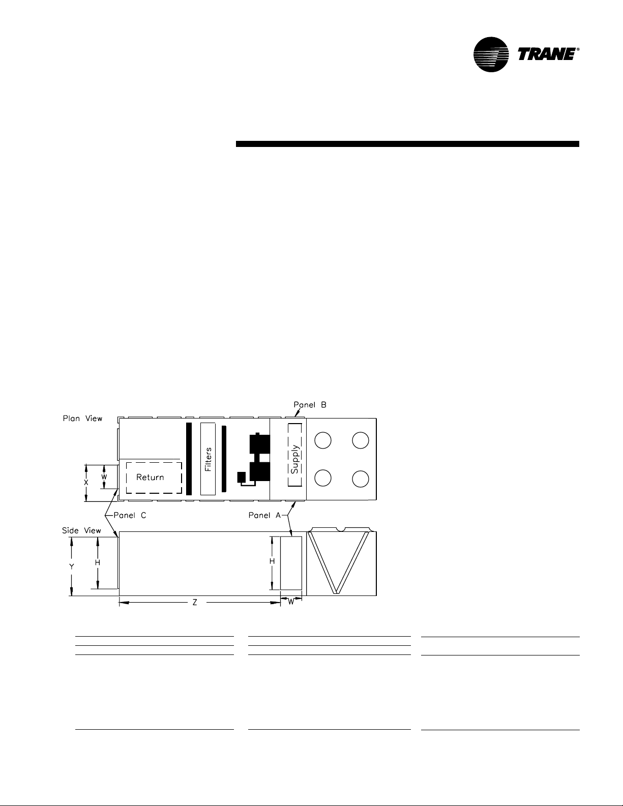
SXHF, SFHF, SLHF, SSHF Units
Figure A C-1 is a simplified sketc h of the
rooftop showing which panels can be
used for horizontal supply and/or return.
To supply air horizontally , the panels that
normally house the heat accessory
controls (Panel A) and the g as heat
barometric dampers (Panel B) can be
removed and either of the openings
horizontal supply and return applies to
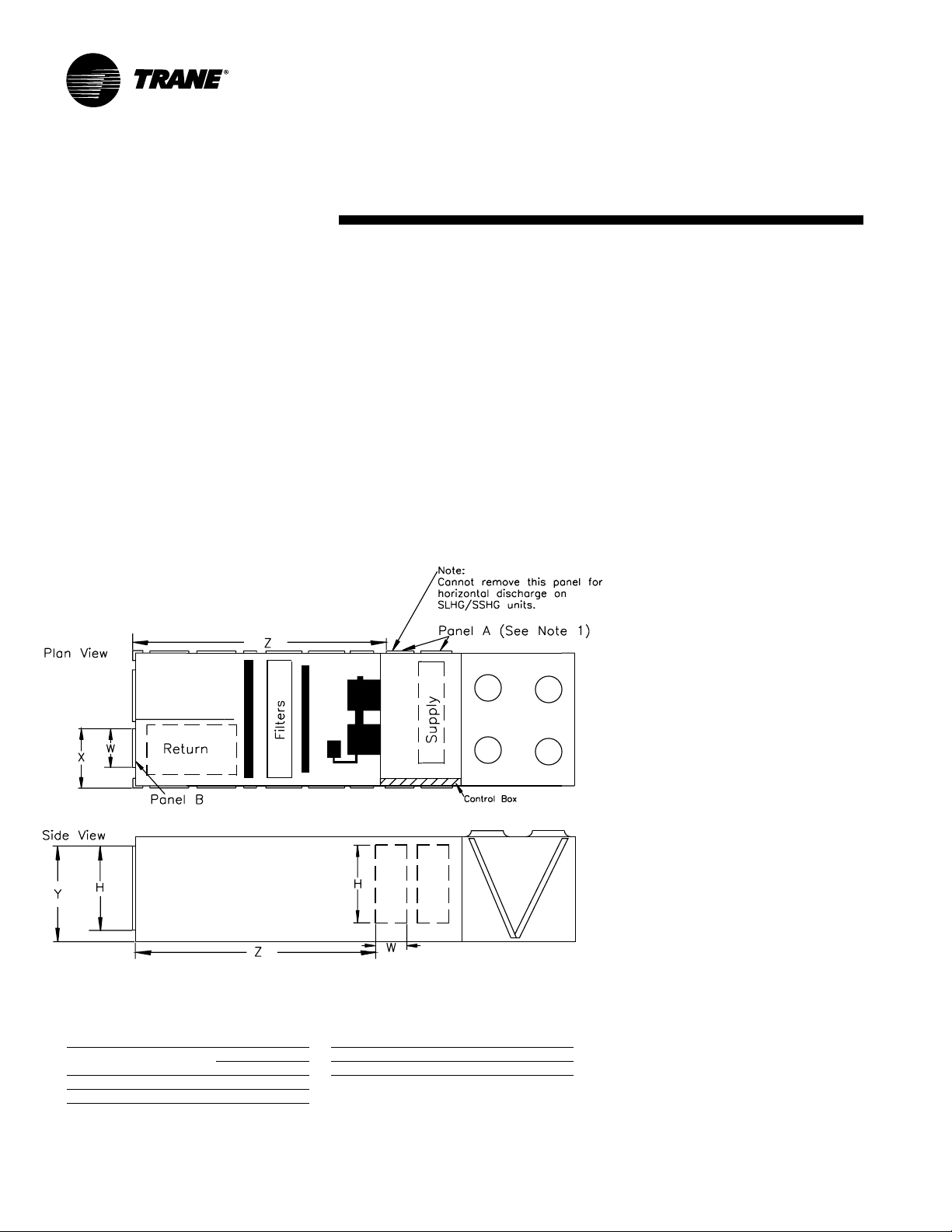
Figure AC-2 Horizontal Discharge Panel Dimensions — 20 - 75 Tons SXHF, SFHF, SLHF, SSHF Units
Note: Cannot remove Panel A
for horizontal discharge on
SFHF, SLHF, SSHF Units.
used as a unit discharge (see note 1). To
return air horizontally , the exhaust fan
access door (Panel C) can be removed
and used as a return opening. T ables A C1, 2 and 3 show dimensions for those
panels.
Horizontal Disc har ge on SXHF, SFHF,
SLHF and SSHF Rooftops (20 to 75 tons)
The SXHF (extended casing cooling
only), SFHF (gas heat), SSHF (steam
heat) and SLHF (hot water heat) rooftops
can be field modified to supply and
return air horizontally without the use of
a horizontal supply/return curb.
To supply air horizontally on SXHF only ,
the panels that normally house the heat
accessory controls (Panel A) and the g as
heat barometric dampers (Panel B) can
be removed and either of the openings
used as a unit discharge. To return air
horizontally , the exhaust fan access door
(Panel C) can be removed and used as a
return opening.
1. For horizontal discharge on SFHF, SLHF and SSHF
units, only the Panel B can be removed. Panel A
cannot be used due to the location of the heating
coils.
2. For horizontal discharge on SFHF (gas heat) models,
the block off under the heater must be removed.
After removal, a support must be added for the drain
tube.
3. Supply and Return Base openings must be covered
when converting to a horizontal configuration.
Tabl e AC-1 — SXHF, SFHF, SSHF, SLHF —
Panel A and B Dimensions
Model H (in.) W (in.) (in.2) (ft2)
S*HF C20 40.7 25.5 1038 7.2
S*HF C25 40.7 25.5 1038 7.2
S*HF C30 52.7 25.5 1344 9.3
S*HF C40 64.5 34.5 2225 15.5
S*HF C50 76.7 34.5 2646 18.4
S*HF C55 76.7 34.5 2646 18.4
S*HF C60 64.6 34.5 2229 15.5
S*HF C70 64.6 34.5 2229 15.5
S*HF C75 64.6 34.5 2229 15.5
Notes:
1. Add an extra 0.20-inches pressure drop to the supply external static to account for the extra turn the air is making.
2. The openings all have a 1.25-inch lip around the perimeter to facilitate ductwork attachment.
3. If exhaust fans are being used, provisions should be made for access to the exhaust components, since the access door is now being used as a return.
4. Use the dimensions provided and the supply Cfm to calculate the velocity (ft/min) through the openings to be sure they are acceptable.
Total Area (H X W)
Table AC- 2 — SXHF, SFHF, SSHF, SLHF —
Panel C Dimensions
Model H (in.) W (in.) (in.2) (ft2)
S*HF C20 40.7 34.5 1404 9.8
S*HF C25 40.7 34.5 1404 9.8
S*HF C30 52.7 34.5 1818 12.6
S*HF C40 64.5 34.5 2225 15.5
S*HF C50 76.7 34.5 2646 18.4
S*HF C55 76.7 34.5 2646 18.4
S*HF C60 64.6 34.5 2229 15.5
S*HF C70 64.6 34.5 2229 15.5
S*HF C75 64.6 34.5 2229 15.5
* = X, F , L, or S
T otal Area (H X W)
Tabl e AC-3 — SXHF, SFHF, SSHF, SLHF —
X, Y and Z Dimensions
Model X (in.) Y (in.) Z (in.)
S*HF C20 35.5 44.0 201.5
S*HF C25 35.5 44.0 201.5
S*HF C30 35.5 56.0 201.5
S*HF C40 44.5 67.8 237.0
S*HF C50 44.5 80.0 237.0
S*HF C55 44.5 80.0 237.0
S*HF C60 44.5 68.0 237.5
S*HF C70 44.5 68.0 237.5
S*HF C75 44.5 68.0 237.5
11RT-PRC01 0-EN
Page 12
Application
Considerations
Figure AC-3 is a simplified sketc h
showing which panels can be used for
horizontal supply and/or return. On 90 to
130 ton units, only one side of the
extended casing may be used for
horizontal supply because of the
location of the unit control panel. There
are, however, on SXHF models two
panels (Panels A) on the side opposite
the control box which can be removed
along with the vertical support whic h
separates the two. Removal of the
vertical support is optional, but will
ensure maximum airflow. On SLHG,
SSHG models only one of the Panel A’s
may be used for horizontal supply
Figure AC-3 — Horizontal Dischar ge P anel Dimensions — 90 - 130 Tons SXHG, SLHG, SSHG Units
because of the location of the heating
coil. Horizontal return is accomplished in
much the same way as on S*HFs by
removing the exhaust fan access door
(Panel B). See Tables A C-4 and 5 for
S*HG panel dimensions.
When using an IntelliPak™ Rooftop for
horizontal supply and return, an
additional pressure drop must be added
to the supply external static to account
for the 90 degree turn the air is making.
This additional pressure drop depends
on airflow and rooftop size, but a range
of 0.10 inc hes to 0.30 inches can be
expected. The openings on the rooftop
all have a one inch lip around the
perimeter to facilitate ductwork
attac hment. If exhaust fans are being
used on an IntelliPak Rooftop unit with
horizontal return, provisions should be
made for access to the exhaust
components, since the access door
opening is now being used as a return.
Perhaps the return ductwork attac hment
to the rooftop can include a section of
removable duct. Use the dimensions
provided and the supply and exhaust
CFM to calculate the velocity (ft/min)
through the openings.
Horizontal Dischar g e SXHG, SLHG,
SSHG Rooftops (90 to 130 t ons)
The SXHG, SLHG, SSHG rooftops can be
field modified to supply and return air
horizontally without the use of a
horizontal supply/return curb.
To supply air horizontally , use Panel A
only. The Panel on the opposite side
cannot be used due to the location of the
unit control Panel. SXHG rooftop air
conditioners do not have a panel
configuration like the 20 to 75 ton
rooftops. To achieve maximum airflow,
vertical support can be removed af ter the
unit has been placed on the roof curb. It
is secured by four screws. (See Note 1)
For horizontal disc harge on SLHG and
SSHG units, only the Panel A next to the
condenser fan section can be removed.
The other Panel A next to the supply fan
cannot be used due to the location of the
heating coils.
To return air horizontally, the exhaust fan
access door (Panel B) can be removed
and used as a return opening.
Note:
1. SXHG units have two Panel A’s that can be removed. Once unit is installed, panel(s) and the 61/2” vertical
support channel in between may be removed.
Table AC-4 — SXHG, SLHG, SSHG —
Panel A and B Dimensions
Panel H (in.) W (in.) (in.2) (ft2)
A 72.7 27.5 1999 13.9
B 72.7 34.5 2508 17.4
Notes:
1. Add an extra 0.20-inches pressure drop to the
supply external static to account for the extra turn
the air is making.
2. The openings all have a 1.25-inch lip around the
perimeter to facilitate ductwork attachment.
Total Area (H X W)
Table AC-5 — SXHG, SLHG, SSHG —
X, Y and Z Dimensions
Model X (in.) Y (in.) Z (in.)
S*HG 90-130 69.0 77.8 244.7
* = X, L, or S
3. If exhaust fans are being used, provisions should
be made for access to the exhaust components,
since the access door is now being used as a
return.
4. Use the dimensions provided and the supply Cfm
to calculate the velocity (ft/min) through the
openings to be sure they are acceptable.
RT-PRC010-EN12
Page 13

Application
Considerations
High Capacity Evaporat or Coil
Rooftops are popular because of their
“pac kaged” nature. Everything needed
is contained in one box; mix-matc hing is
neither necessary nor available. With this
convenience comes some
disadvantages; one is the rooftop’s
cooling capacity may not exactly match
the building load. It is conceivable that a
50 ton rooftop would need to be used on
an application that is 41 tons, simply
because the 40 ton rooftop does not
meet capacity.
In order to avoid such occur rences, and
to more closely match the roof top’s
capacity to the building load, a high
capacity evaporator coil option is
available on all IntelliPak™ R ooftops 20
to 105 tons. These high capacity coils
have an increased number of evaporator
coil rows as compared to standard and
enhanced evaporator tube surfaces,
resulting in a higher capacity. Capacity
tables for both standard and high
capacity coils are available in the cooling
data section of this catalog. See T able
PD-43 for the pressure drops associated
with the high capacity coil option. This
pressure drop should be added to the
total static pressure used to size the
supply fan motor.
Low Ambient Operation — Human
Interface Recommendations
Who wants to be on a roof at sub-zero
temperatures? W e can understand a
service technician’s reluctance to do this;
that’s why we recommend using a
remote mounted Human Interface Panel.
The service technician can troubleshoot
and diagnose in the comfort of a
mechanical room.
Corrosiv e Atmospheres
T rane’s IntelliPak Rooftops are designed
and built to industrial standards and will
perform to those standards for an
extended period depending on the hours
of use, the quality of maintenance
performed, and the regularity of that
maintenance. One factor that can have
an adverse effect on unit life is its
operation in a corrosive environment.
When rooftops are operated in corrosive
environments, T rane recommends that
copper fins be utilized on the condenser
and/or evaporator coil. Because copper
is more resistant to corrosion than
aluminum, coil life expectancy is greatly
increased. Some industry applications
expose equipment to corrosive agents
that even copper cannot fully resist. For
those special applications, a baked
phenolic resin coating (i.e. Heresite) is
highly desirable. Baked phenolic
coatings or copper fins on the condenser
and/or evaporator coils are available on
T rane’s IntelliPak Rooftops.
V entilation Ov er r ide Sequences
One of the benefits of using an exhaust
fan rather than a return fan, in addition
to the benefits of lower energy usage
and improved building pressurization
control, is that the rooftop can be used
as part of a ventilation override system.
Several types of sequences can be easily
done when exhaust fans are a part of the
rooftop system.
What would initiate the ventilation
override control sequence? Typically, a
manual switch is used and located near
the fire protection control panel. This
enables the fire department access to the
control for use during or after a fire. It is
also possible to initiate the sequence
from a field-installed automatic smoke
detector. In either case, a contact closure
begins the ventilation override control
sequence. CAUTION!: The ventilation
over r ide syst em should not be used to
signal the presence of smoke caused b y
a fire.
T rane can pro vide five (5) different
ventilation override sequences on both
CV and VAV IntelliP ak Roof tops. For your
convenience the sequences can be
factory preset or fully field editable from
the Human Interface Panel or T racer™.
Any or all five sequences may be
“loc ked” in by the user at the Human
Interface Panel.
The user can customize up to five (5)
different over ride sequences for
purposes such as smoke control. The
following parameters within the unit can
be defined for each of the five
sequences:
• Supply Fan — on/off
• Inlet Guide Vanes — open/closed/
controlling
• Variable Frequency Driv es — on (60
Hz)/off (0 Hz)/controlling
• Exhaust F an — on/off
• Exhaust Dampers — open/closed
• Economizer dampers — open/closed
• Heat — off/controlling (output for) VAV
Boxes — open/controlling
Compressors and condenser fans are
shut down for any V entilation Override
sequence. Factory preset sequences
include unit Off, Exhaust, P urge, Purge
with duct pressure control, and
Pressurization. Any of the user-defined
V entilation Override sequences can be
initiated by closing a field supplied
switch or contacts connected to an input
on the Ventilation Override Module. If
more than one ventilation override
sequence is being requested, the
sequence with the highest priority is
initiated. Refer to the Sequence of
Operation provided in the Control
section of this catalog for more details
on each over ride sequence.
Natural Gas Heating Considerations
The IntelliPak standard, or limited
modulation, gas heat exchangers are not
recommended for applications with
mixed air conditions entering the heat
exchanger below 50°F. Mixed air
temperatures below 50°F can cause
condensation to form on the heat
exchanger , leading to premature failure.
13RT-PRC01 0-EN
Page 14

Application
Considerations
For increased reliability , the
recommendation in these applications is
full modulation gas heat. For airflow
limitations and temperature rise across
the heat exchanger information, see
Table PD-24, 25 and RT-EB-104.
Acoustical Considerations
The ideal time to make provisions to
reduce sound transmission to the space
is during the project design phase.
Proper placement of rooftop equipment
is critical to reducing transmitted sound
levels to the building. The most
economical means of avoiding an
acoustical problem is to place any
rooftop equipment away from
acoustically critical area. If possible,
rooftop equipment should not be located
directly above areas such as: of fices,
conference rooms, executive office areas
and classrooms. Ideal locations are
above corridors, utility rooms, toilet
facilities, or other areas where higher
sound levels are acceptable.
Several basic guidelines for unit
placement should be followed to
minimize sound transmission through
the building structure:
1
Never cantilever the condensing section
of the unit. A structural cross member
must support this end of the unit.
2
Locate the unit’s center of gravity close
to or over a column or main support
beam to minimize roof deflection and
vibratory noise.
3
If the roof structure is very light, roof
joists should be replaced by a structural
shape in the critical areas described
above.
4
If several units are to be placed on one
span, they should be staggered to
reduce deflection over that span.
It is impossible to totally quantify the
effect of building structure on sound
transmission, since this depends on the
response of the roof and building
members to the sound and vibration of
the unit components. However, the
guidelines listed above are experience
proven guidelines which will help reduce
sound transmission.
There are several other sources of unit
sound, i.e., supply fan, compressors,
exhaust fans, condenser fans and
aerodynamic noise generated at the duct
fittings. Refer to the ASHRAE
Applications Handbook, Chapter 42, 1991
edition for guidelines for minimizing the
generation of aerodynamic noise
associated with duct fittings.
T rane’s Engineering Bulletin RT-EB-80
describes various duct installation
considerations specifically addressing
indoor sound level concerns. This
bulletin includes sound power data on
T rane’s IntelliPak Rooftops 20 to 1 30 tons.
Ask your local Trane representative for
this informative engineering bulletin.
The VariT rane™ Computeriz ed Duct
Design Program can be used to analyze
the truck duct, run-out duct, VAV control
unit and terminal unit noise attenuation.
This program quantifies the airborne
sound generation that can be expected
in each terminal so that the designer can
identify potential sound problems and
make design alterations before
equipment installation.
The Trane Acoustics Program (TAP)
allows modeling of rooftop installation
parameters. The output of this program
shows the resulting indoor NC level for
the modeled installation. This program is
available from Trane’s Customer Direct
Service Network™ (C.D.S.), ask your
local Trane representative for additional
information on this program.
Clearance Requirements
The recommended clearances identified
with unit dimensions should be
maintained to assure adequate
serviceability, maximum capacity and
peak operating efficiency . A reduction in
unit clearance could result in condenser
coil starvation or warm condenser air
recirculation. If the clearances shown are
not possible on a particular job, consider
the following:
• Do the clearances available allow for
major service work such as c hanging
compressors or coils?
• Do the clearances available allow for
proper outside air intake, exhaust air
removal and condenser airflow?
• If screening around the unit is being
used, is there a possibility of air
recirculation from the exhaust to the
outside air intake or from condenser
exhaust to condenser intake?
Actual clearances which appear
inadequate should be reviewed with a
local Trane sales engineer.
When two or more units are to be placed
side by side, the distance between the
units should be increased to 150 percent
of the recommended single unit
clearance. The units should also be
staggered as shown in Figure AC-4 for
two reasons:
1
To reduce span deflection if more than
one unit is placed on a single span.
Reducing deflection discourages sound
transmission.
2
To assure proper diffusion of exhaust air
before contact with the outside air intake
of adjacent unit.
RT-PRC010-EN14
Page 15
Application
Considerations
Duct Design
It is important to note that the rated
capacities of the rooftop can be met only
if the rooftop is properly installed in the
field. A well-designed duct system is
essential in meeting these capacities.
The satisfactory distribution of air
throughout the system requires that
there be an unrestricted and uniform
airflow from the rooftop discharge duct.
This discharge section should be straight
for at least several duct diameters to
allow the conversion of fan energy from
velocity pressure to static pressure.
However, when job conditions dictate
elbows be installed near the rooftop
outlet, the loss of capacity and static
pressure may be reduced through the
use of guide vanes and proper direction
of the bend in the elbow. The high
velocity side of the rooftop outlet should
be directed at the outside radius of the
elbow rather than the inside as
illustrated in Figure AC-5.
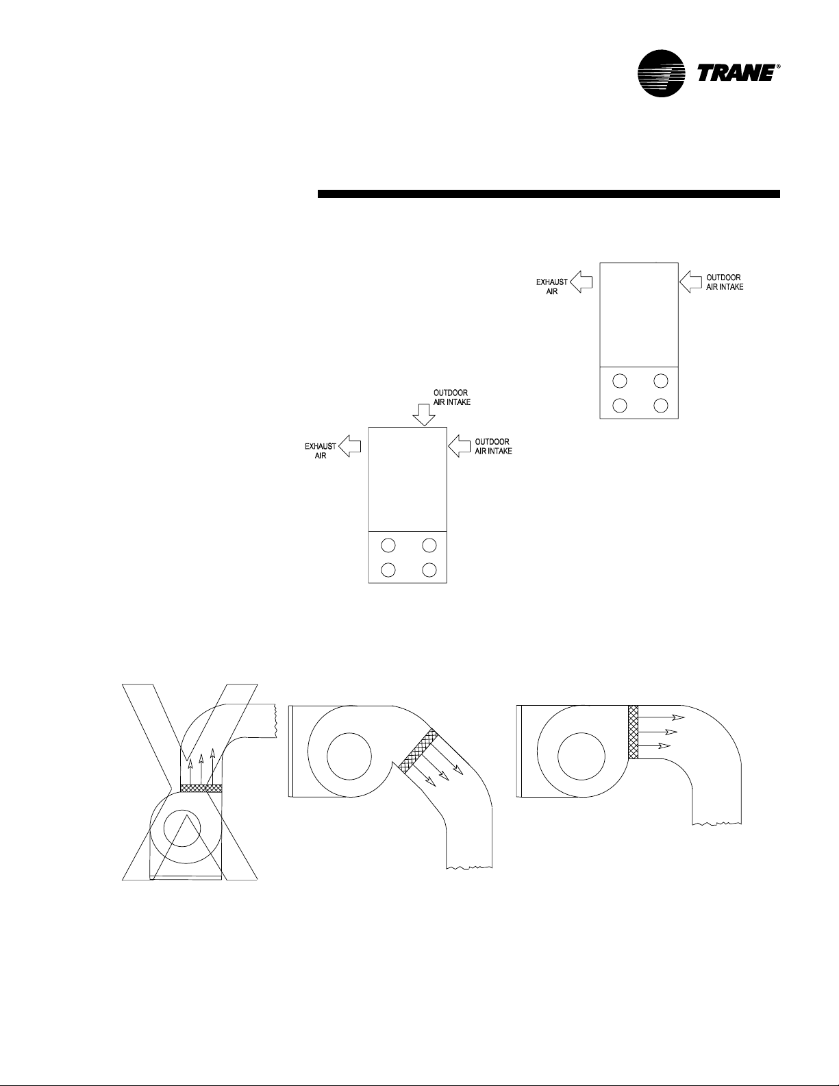
Figure AC-4 — Unit Placement
1
2
1. 20-40 ton models have only one outdoor air intake.
50 - 75 ton models have two outdoor air intakes.
2. 90-130 ton models have two outdoor air intakes on
the backside of the unit and one small air intake at
the end of the unit.
Improper
Figure AC-5 — Duct Design
Proper
15RT-PRC01 0-EN
Page 16

Selection
Pr ocedure
This section outlines a step-by-step
procedure that may be used to select a
T rane single-z one air conditioner . The
sample selection is based on the
following conditions:
• Summer outdoor design conditions —
95 DB/76 WB ambient temperature
• Summer room design conditions —78
DB/65 WB
• Total cooling load — 430 MBh (35.8
tons)
• Sensible cooling load — 345 MBh (28.8
tons)
• Outdoor air ventilation load — 66.9
MBh
• Return air temperature — 80 DB/65 WB
Winter Design:
• Winter outdoor design conditions —0 F
• Return air temperature — 70 F
• Total heating load — 475 MBh
• Winter outdoor air ventilation load —
133 MBh
Air Delivery Data:
• Supply fan cfm — 17,500 cfm
• External static pressure — 1.2 in wg
• Minimum outdoor air ventilation —
1,750 cfm
• Exhaust fan cfm — 12,000 cfm
• Return air duct neg ative static pressure
— 0.65 in wg
Electrical Charact er istics:
• V oltage/cycle/phase — 460/60/3 Unit
Accessories:
• Gas fired heat exc hanger — high heat
module
• Throwaway filters
• Economizer
• Modulating 1 00 percent exhaust/
return fan
COOLING CAP ACIT Y SELECTION
Step 1 — Nominal Unit Size Selection
A summation of the peak cooling load
and the outside air ventilation load
shows: 430 MBh + 66.9 MBh = 496.9
MBh required unit capacity. From
Table PD-9, a 50 ton unit capacity with
standard capacity evaporator coil at
80 DB/65 WB, 95 F outdoor air
temperature and 17,500 total supply cfm
is 551 MBh total and 422 MBh sensible.
Thus, a nominal 50 ton unit with
standard capacity evaporator coil
is selected.
Step 2 — Evaporator Coil Enter ing
Conditions
Mixed air dry bulb temperature
determination:
Using the minimum percent of OA (1,750
cfm ÷ 17,500 cfm = 1 0 percent),
determine the mixture dry bulb to the
evaporator.
RADB + % OA (O ADB - RADB) = 80 +
(0.10) (95 - 80) = 80 + 1.5 = 81.5 F
Approximate wet bulb mixture
temperature:
RAWB + % O A (O A WB - RA WB) = 65 +
(0.10) (7 6 - 65) = 65 + 1.1 = 66.1 F
Step 3 — Det er mine Supply Fan Mot or
Heat Gain
Having selected a nominal 50 ton unit,
the supply fan bhp can be calculated. The
supply fan motor heat gain must be
considered in final determination of unit
capacity.
Supply Air Fan
Determine unit total static pr essur e at
design supply cfm:
External Static Pressure 1 .2 inc hes
Evaporator Coil 0.25 inches
(Table PD-43)
Return Duct Negative 0.65 inches
Static Pressure
Heat Exchanger 0.31 inches
(Table PD-43)
Throwaway Filter 0.10 inc hes
(Table PD-43)
Economizer w/Exhaust Fan0.12 inches
(Table PD-43)
T rane R oof Curb 0.13 inches
(Table PD-43)
Unit T otal Static Pressure 2.7 6 inc hes
Using total of 17,500 cfm and total
static pressure of 2.76 inches, enter Table
PD-36. T able PD-36 shows 15.3 bhp with
924 rpm.
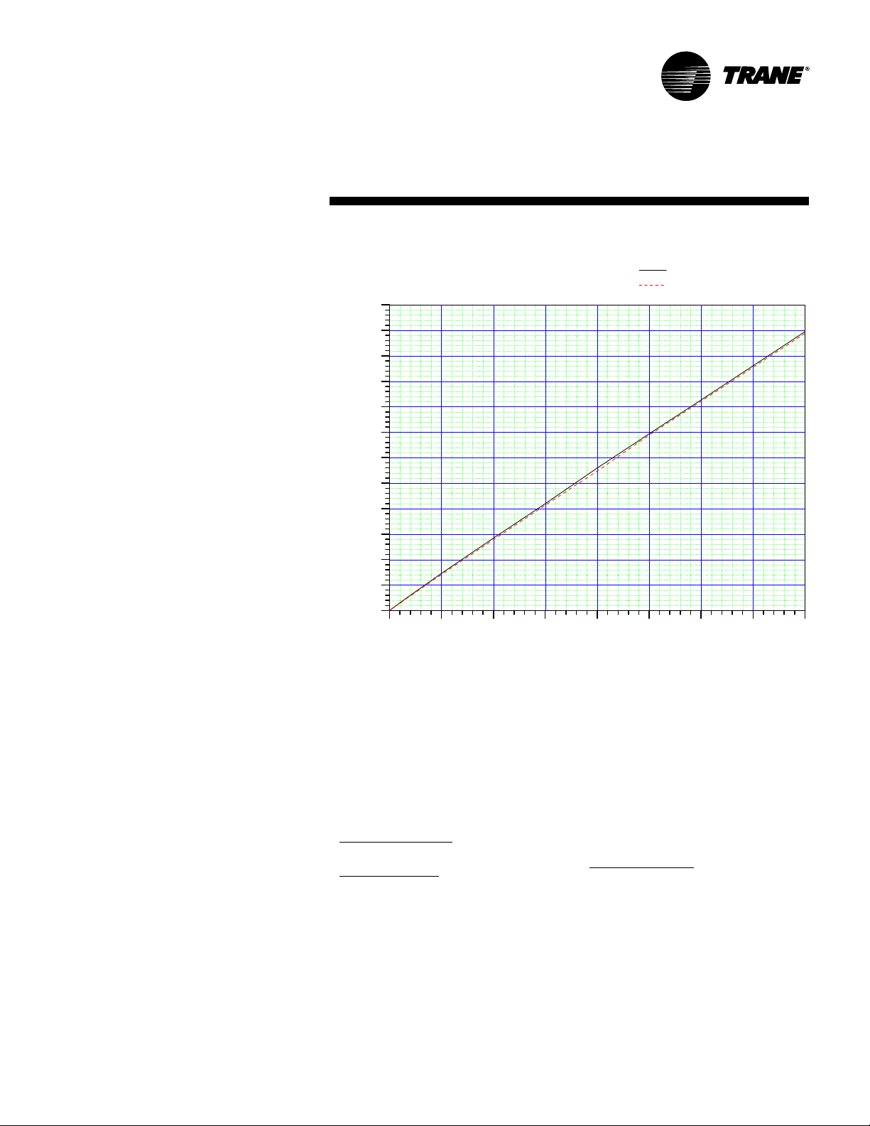
From Chart SP-1 supply fan motor heat
gain = 46.0 MBh.
Step 4 — Det ermine T otal Required
Cooling Capacity
Required capacity = T otal peak load + O A
load + supply air fan motor heat.
Required capacity = 430 + 66.9 +
46.0 = 543 MBh (45.2 tons)
Step 5 — Det ermine Unit Capacity
From Table PD-9, unit capacity at 81 .5 DB/
66.1 WB entering the evaporator , 1 7,500
supply air cfm, 95 F outdoor ambient, is
561 MBh (45.8 tons) with 426 MBh
sensible.
Step 6 — Det ermine Lea ving Air
Temperature
Unit sensible heat capacity corrected for
supply air fan motor heat = 426 MBh - 46
MBh = 380 MBh.
Supply air dry bulb temperature
difference =
Sensible Btu =
1.085 x Supply cfm
380 MBh ÷ (1.085 x 17,500 cfm)
= 20.0 F
Supply air dry bulb = 81.5 DB - 20.0
= 61.5 F
Unit enthalpy difference =
Total Btu =
4.5 x Supply cfm
561 MBh ÷ (4.5 x 17,500 cfm) =
7.12 Btu/lb
Leaving enthalpy = h(ent WB) -
h(diff). From Table 21-1 h(ent WB) =
30.9 Btu/lb
Leaving enthalpy = 30.9 Btu/lb - 7.12
Btu/lb = 23.78 Btu/lb
Supply air wet bulb = 55.9
Leaving air temperature = 61.5
DB/55.9 WB
RT-PRC010-EN16
Page 17
Selection
Pr ocedure
HEA TING CAPACITY SELECTION
Step 1 — Det er mine Air T emperat ure
Entering Heating Module
Mixed air temperature = RADB + % OA
(OADB - RADB) = 70 + (0.1 0) (0 - 70) = 63
F
Supply air fan motor heat temperature
rise = 46,000 Btu ÷ (1.085 x 17,500 cfm) =
2.42 F
Air temperature entering heating
module = 63.0 + 2.42 = 65.4 F
Step 2 — Det er mine Total Wint er Heating
Load
Total winter heating load = peak heating
load + ventilation load - supply fan
motor heat = 475 + 133 - 46.0 = 562 MBh
Electric Heating Syst em
Unit operating on 460/60/3 power supply.
From Table PD-30, kw may be selected
for a nominal 50 ton unit operating
460-volt power. The 170 kw heat module
(580.1 MBh) will satisfy the winter
heating load of 563 MBh.
Table PD-28 shows an air temperature
rise of 30.6 F for 17,500 cfm through
the 170 kw heat module.
Unit supply temperature at design
heating conditions = mixed air
temperature + air temperature rise = 65.4
F + 30.6 F = 96.0 F.
Gas Heating System (Natural Gas)
From Table PD-24 select the high heat
module (697 MBh output) to satisfy
winter heating load of 563 MBh at unit
cfm.
Table PD-26 also shows an air
temperature rise of 36.0 F for 17,500 cfm
through the heating module.
Unit supply temperature at design
heating conditions = mixed air
temperature + air temperature rise = 65.4
F + 36.0 F = 10 1.4 F.
Hot Water Heating
Assume a hot water supply temperature
of 190 F. Subtract the mixed air
temperature from the hot water
temperature to determine the ITD (initial
temperature difference).
Chart SP-1 — Fan Motor Heat
120
110
100
90
80
70
60
50
40
FAN MOTOR HEAT - MBH
30
20
10
0
0 5 10 15 20 25 30 35 40
MOTOR BRAKE HORSE POWER
ITD = 190 F - 65.4 F = 1 25 F. Divide the
winter heating load by ITD = 563 MBh ÷
125 F = 4.50 Q/ITD.
From Table PD-31, select the low heat
module. By interpolation, a Q/ITD of 4.50
can be obtained at a gpm at 25.7.
Water pressure drop at 25.7 gpm is 0.57
ft. of water. Heat module temperature
rise is determined by:
Total Btu = ∆T
1.085 x Supply cfm
563,000 = 29.7 F
(1.085 x 17,500)
Unit supply air temperature = mixed air
temperature + air temperature rise = 65.4
+ 29.7 = 95 F.
Steam Heating System
Assume a 15 psig steam supply .
From Table PD-27, the saturated
temperature steam is 250 F. Subtract
mixed air temperature from the steam
STANDARD MOTOR
HIGH EFFICIENCY MOTOR
temperature to determine ITD. ITD = 250
F - 65.4 F = 185 F.
Divide winter heating load by ITD =
563 MBh ÷ 185 F = 3.04 Q/ITD.
From Table PD-26, select the high heat
module. The high heat module at 17,500
cfm has a Q/ITD = 5.11.
Heat module capacity, Q = ITD x Q/ITD =
185 F x 5.11 Q/ITD = 945 MBh
Heat module air temperature rise
T otal Btu
=
1 .085 x Supply cfm
945 Btu ÷ (1.085 x 17,500 cfm) = 49.8 F.
Unit supply temperature at design
conditions = mixed air temperature + air
temperature rise = 65.4 F + 49.8 F = 115 F.
17RT-PRC01 0-EN
Page 18

Selection
Pr ocedure
AIR DELIVERY PROCEDURE
Supply fan performance tables include
internal resistance of rooftop. For total
static pressure determination, system
external static must be added to
appropriate component static pressure
drop (evaporator coil, filters, optional
economizer , optional exhaust fan,
optional heating system, optional
cooling only extended casing, optional
roof curb).
Supply Fan Motor Sizing
The supply fan motor selected in the
cooling capacity determination was 15.3
bhp and 924 rpm. Thus, a 20 hp supply
fan motor is selected. Enter T able PD-45
to select the proper drive. For a 50 ton
rooftop with 20 hp motor , a drive
number 9 — 900 rpm is selected.
Exhaust Fan Motor Sizing
The exhaust fan is selected based on
total return system negative static
pressure and exhaust fan cfm. Return
system negative static include return
duct static and roof curb static pressure
drop.
Return duct static pressure = 0.65 inches
T rane roof curb (Table PD-43) = 0.12
inches
Total return system negative static
pressure = 0.77 inches
Exhaust fan cfm = 12,000 cfm
From Table PD-47, the required bhp is
3.45 hp at 574 rpm. Thus, the exhaust fan
motor selected is 5 hp.
To select a drive, enter T able PD-49 for a 5
hp motor for a 50 ton unit. Drive
selection number 6 — 600 rpm.
Where altitudes are significantly above
sea level, use T ables PAF-2 and P AF-3 and
Figure P AF-1 for applicable correction
factors.
UNIT ELECTRICAL REQUIREMENTS
Selection procedures for electrical
requirements for wire sizing amps,
maximum fuse sizing, and dual element
fuses are given in the electrical service
section of this catalog.
Altitude Corr ections
The rooftop performance tables and
curves of this catalog are based on
standard air (.075 lbs/ft). If the rooftop
airflow requirements are at other than
standard conditions (sea level), an air
density correction is needed to project
accurate unit performance.
Figure P AF-1 shows the air density ratio
at various temperatures and elevations.
T rane roof tops are designed to operate
between 40 and 90 degrees Fahrenheit
leaving air temperature.
The procedure to use when selecting a
supply or exhaust fan on a rooftop for
elevations and temperatures other than
standard is as follows:
1
First, determine the air density ratio
using Figure P AF-1 .
2
Divide the static pressure at the
nonstandard condition by the air
density ratio to obtain the corrected
static pressure.
3
Use the actual cfm and the corrected
static pressure to determine the fan rpm
and bhp from the rooftop performance
tables or curves.
4
The fan rpm is correct as selected.
5
Bhp must be multiplied by the air
density ratio to obtain the actual
operating bhp.
RT-PRC010-EN18
Page 19

Selection
Pr ocedure
In order to better illustrate this
procedure, the following example is
used:
Consider a 60 ton rooftop unit that is to
deliver 18,000 actual cfm at 3-inches total
static pressure (tsp), 55 F leaving air
temperature, at an elevation of 5,000 ft.
1
From Figure PAF -1, the air density ratio is
0.86.
2
Tsp = 3.0-inches / 0.86 = 3.49 inc hes tsp.
3
From the performance tables: a 60 ton
rooftop (without inlet vanes) will deliver
18,000 cfm at 3.49-inches tsp at 906 rpm
and 21 .25 bhp.
4
The rpm is correct as selected - 906rpm.
5
Bhp = 21 .25 x 0.86 = 18.3 bhp actual.
Compressor MBh, SHR, and kw should
be calculated at standard and then
converted to actual using the cor rection
factors in Table PAF-2. Apply these factors
to the capacities selected at standard cfm
so as to correct for the reduced mass
flow rate across the condenser.
Heat selections other than gas heat will
not be affected by altitude. Nominal gas
capacity (output) should be multiplied by
the factors given in Table P AF-3 before
calculating the heating supply air
temperature.
HEA TING CAPACITY SELECTION
Step 1 — Det er mine Air T emperat ure
Entering Heating Module
Mixed air temperature = RADB + % OA
(OADB - RADB) = 70 + (0.10) (0 - 70) = 63
F
Supply air fan motor heat temperature
rise = 46,000 Btu ÷ (1.085 x 1 7,500 cfm) =
2.42 F
Air temperature entering heating
module = 63.0 + 2.42 = 65.4 F
19RT-PRC01 0-EN
Page 20

Model
Number
Description
S F H F C 5 5 F H A 5 5 C 6 9 D 3 0 0 1 0 0 0 0 0 0 0 0 0 0 0 0 0 0 0 0 0 0
1 2 3 4 5 6 7 8 9 101112131415161718192021222324252627 28 29 30 31 32 33 34 35 36 37 38
DIGIT 1 — UNIT TYPE
S = Self-Contained (Packaged Rooftop)
DIGIT 2 — UNIT FUNCTION
A = DX Cooling, No Heat
E = DX Cooling, Electric Heat
F = DX Cooling, Natural Gas Heat
L = DX Cooling, Hot Water Heat
S = DX Cooling, Steam Heat
X = DX Cooling, No Heat, Extended Casing
DIGIT 3 — UNIT AIRFLOW
H = Single Zone
DIGIT 4 — DEVELOPMENT SEQUENCE
F = Sixth
DIGITS 5,6,7 — NOMINAL CAPACITY
C20 = 20 T ons C55 = 55 T ons
C25 = 25 T ons C60 = 60 T ons
C30 = 30 T ons C70 = 70 T ons
C40 = 40 T ons C75 = 75 T ons
C50 = 50 T ons
DIGIT 8 — POWER SUPPLY (See Notes)
4 = 460/60/3 XL E = 200/60/3 XL
5 = 575/60/3 XL F = 230/60/3 XL
Note: SEHF units (units with electric heat)
utilizing 208V or 230V require dual power
source.
DIGIT 9 — HEATING CAPACITY
Note: When the second digit calls for “F”
(Gas Heat), the following values apply:
Additionally , please note G and M available
ONLY on 50 Ton models and above.
H = High Heat-2-Stage P = High Heat-Full
L = Low Heat-2-Stage Modulation
0 = No Heat M = Low Heat-Full
J = High Heat-Limited Modulation
Modulation
G = Low Heat-Limited
Modulation
Note: When the second digit calls for “E”
(electric heat), the following values appl y :
D = 30 KW R = 130 KW
H = 50 KW U = 150 KW
L = 70 KW V = 170 KW
N = 90 KW W = 190 KW
Q = 110 KW
Note: When the second digit calls for ‘’L’ ’
(Hot Water) or ‘’S’ ’(Steam) Heat, one of the
following valve size values must be in Digit 9:
High Heat Coil: 1 = .50”, 2 = .75”, 3 = 1”,
4 = 1.25”, 5 = 1.5”, 6 = 2”.
Low Heat Coil: A = .50”, B = .75”, C = 1”,
D = 1.25”, E = 1.5”, F = 2”.
DIGIT 10 — DESIGN SEQUENCE
A = First (Factory Assigned)
Note: Sequence may be any letter A thru Z,
or any digit 1 thru 9.
DIGIT 11 — EXHAUST OPTION
0 = None
1 = Barometric
2 = 100%, 1.5 HP W/Statitrac
3 = 100%, 3 HP W/Statitrac
4 = 100%, 5 HP W/Statitrac
5 = 100%, 7.5 HP W/Statitrac
6 = 100%, 10 HP W/Statitrac
7 = 100%, 15 HP W/Statitrac
8 = 100%, 20 HP W/Statitrac
A = 50%, 1.5 HP
B = 50%, 3 HP
C = 50%, 5 HP
D = 50%, 7.5 HP
E = 100%, 1.5 HP W/O Statitrac (CV Only)
F = 100%, 3 HP W/O Statitrac (CV Only)
G = 100%, 5 HP W/O Statitrac (CV Only)
H = 100%, 7.5 HP W/O Statitrac (CV Only)
J = 100%, 10 HP W/O Statitrac (CV Only)
K = 100%, 15 HP W/O Statitrac (CV Only)
L = 100%, 20 HP W/O Statitrac (CV Only)
DIGIT 12 — EXHAUST AIR FAN DRIVE
0 = None 8 = 800 RPM
4 = 400 RPM 9 = 900 RPM
5 = 500 RPM A = 1000 RPM
6 = 600 RPM B = 1100 RPM
7 = 700 RPM
DIGIT 13 — FILTER
A = Throwaway
B = Cleanable Wire Mesh
C = High-Efficiency Throwawa y
D = Bag With Prefilter
E = Cartridge With Prefilter
F = Throwaway Filter Rack Less Filter
Media
G = Bag Filter Rack Less Filter Media
DIGIT 14 — SUPPLY AIR FAN HP
1 = 3 HP 4 = 10 HP 7 = 25 HP
2 = 5 HP 5 = 15 HP 8 = 30 HP
3 = 7.5 HP 6 = 20 HP 9 = 40 HP
DIGIT 15 — SUPPLY AIR FAN DRIVE
5 = 500 RPM B = 1100 RPM
6 = 600 RPM C = 1200 RPM
7 = 700 RPM D = 1300 RPM
8 = 800 RPM E = 1400 RPM
9 = 900 RPM F = 1500 RPM
A= 1000 RPM G = 1600 RPM
DIGIT 16 — FRESH AIR
A = No F resh Air
B = 0-25% Manual
D = 0-100% Economizer
DIGIT 17 — SYSTEM CONTROL
1 = Constant Volume Control
2 = VAV Supply Air Temperature Control
w/o Inlet Guide Vanes
3 = VAV Supply Air Temperature Control
w/ Inlet Guide Vanes
4 = Space Pressure Control with Exhaust
VFD w/o Bypass
5 = Space Pressure Control with Exhaust
VFD and Bypass
6 = VAV Supply Air Temperature Control
with VFD w/o Bypass
7 = VAV Supply Air Temperature Control
with VFD and Bypass
8 = Supply and Exhaust Fan with VFD
w/o Bypass
9 = Supply and Exhaust Fan with VFD
and Bypass
DIGIT 18 — ACCESSOR Y PANEL
0 = None
A = BAYSENS008*
B = BAYSENS010*
C = BAYSENS013*
D = BAYSENS014*
E = BAYSENS019*
F = BAYSENS020*
G = BAYSENS021*
Note: *Asterisk indicates current model
number digit A, B, C, etc. These sensors
can be ordered to ship with the unit.
DIGIT 19 — AMBIENT CONTROL
0 = Standard
1 = 0° Fahrenheit
DIGIT 20 — AGENCY APPROVAL
0 = None (UL Gas Heater, see note)
1 = UL
2 = CSA
Note: Includes UL classified gas heating
section only when second digit of Model No.
is a “F .”
DIGITS 21 - 38 — MISCELLANEOUS
21 A = Unit Disconnect Switch
22 B = Hot Gas Bypass
23 0 = Without Economizer
C = Economizer Control w/
23 Z = Economizer Control w/
3
23 W = Economizer Control w/Dry Bulb
24 E = Low Leak Fresh Air Dampers
25 F = High Duct Temperature
26 G = High Capacity Evap. Coil
27 H = Copper Fins (Cond. Only)
28 K = Generic B.A.S. Module
29 L = High-Efficiency Motors (Supply
30 M = Remote Human Interface
31 N = Ventilation Override Module
32 R = Extended Grease Lines
33 T = Access Doors
34 V = Inter-Processor Communica
35 Y = Trane Communication
35 7 = LonTalk Communication
36 8 = Spring Isolators
37 6 = Factory-Powered 15A GFI
38 5 = VFD Line Reactor
Comparative Enthalp y
Reference Enthalpy
Thermostat
and Exhaust)
tion Bridge
Interface (TCI) Module
Interface (LCI) Module
Convenience Outlet
1
RT-PRC010-EN20
Page 21

Model
Number
Description
S X H G D 1 1 4 O A H 7 C F 9 D 3 0 0 1 0 0 0 0 0 0 0 0 0 0 0 0 0 0 0 0
1 2 3 4 567 8 9 1011 12131415161718 19 20 21222324252627 282930313233343536
DIGIT 1 — UNIT TYPE
S = Self-Contained (Packaged Rooftop)
DIGIT 2 — UNIT FUNCTION
E = DX Cooling, Electric Heat
F = DX Cooling, Natural Gas Heat
L = DX Cooling, Hot Water Heat
S = DX Cooling, Steam Heat
X = DX Cooling, No Heat, Extended Casing
DIGIT 3 — UNIT AIRFLOW
H = Single Zone
DIGIT 4 — DEVELOPMENT SEQUENCE
G = Seventh
DIGITS 5,6,7 — NOMINAL CAPACITY
C90 = 90 T ons
D11 = 105 Tons
D12 = 115 Tons
D13 = 130 Tons
DIGIT 8 — POWER SUPPLY
4 = 460/60/3 XL
5 = 575/60/3 XL
E = 200/60/3 XL
F = 230/60/3 XL
DIGIT 9 — HEATING CAPACITY
0 = No Heat
H = High Heat - 2-Stage
J = High Heat - Limited Modulation
P = High Heat - Full Modulation
Note:
When the second digit calls for “E”
(electric heat), the following values apply
in the ninth digit:
W = 190 KW
When the second digit calls for ‘’L’’ or
‘’S’’, one of the following valve size
values must be in Digit 9:
High Heat Coil: 3 = 1.0”, 4 = 1.25”, 5 =
1.50”, 6 = 2.0”, 7 = 2.5”
Low Heat Coil: C = 1.0”, D = 1.25”, E =
1.50”, F = 2.0”, G = 2.5”
DIGIT 10 — DESIGN SEQUENCE
A = First (Factory Assigned)
Note: Sequence may be any letter A thru
Z, or any digit 1 thru 9.
DIGIT 11 — EXHAUST OPTION
0 = None
7 = 100%, 15 HP W/Statitrac
8 = 100%, 20 HP W/Statitrac
1. EXAMPLE: Model numbers: SFHFC55FHA55C69D3001N describes a unit with the following characteristics: DX cooling with
natural gas heating, 55 ton nominal cooling capacity, 230/60/3 power supply, high heat model. 100 percent exhaust with
Statitrac, 7.5 HP exhaust fan motor with drive selection No. 5 (500 RPM), high-efficiency throwaway filters, 20 HP supply
fan motor with drive selection No. 9 (900 RPM), 0-100% economizer, VAV supply air temperature control with inlet guide
vanes, no remote panel, standard ambient control, U.L. agency approval. The service digit for each model number
contains 38 digits; all 38 digits must be referenced.
2. EXAMPLE: Model numbers: SXHGD1140AH7CF8D3001 describes a unit with the following characteristics: DX cooling with
extended casing, no heat, 105 ton nominal cooling capacity, 460/60/3 power supply, no heat, 100 percent exhaust with
Statitrac, 30 h.p. exhaust fan motor with drive selection No. 7 — (700 RPM), high-efficiency throwaway filters, 60 hp supply
fan motor with drive selection No. 8 — (900 RPM), economizer, VAV supply air temperature control with inlet guide vanes,
no remote panel, standard ambient, UL agency approval. The service digit for each model number contains 36 digits; all 36
digits must be referenced.
3. Available as standard 460 volt only for 70 and 75 ton models.
9 = 100%, 25 HP W/Statitrac
F = 50%, 15 HP
H = 100%, 30 HP W/Statitrac
J = 100%, 40 HP W/Statitrac
K = 100%, 15 HP W/O Statitrac (CV Only)
L = 100%, 20 HP W/O Statitrac (CV Only)
M = 100%, 25 HP W/O Statitrac (CV Only)
N = 100%, 30 HP W/O Statitrac (CV Only)
P = 100%, 40 HP W/O Statitrac (CV Only)
DIGIT 12 — EXHAUST AIR FAN DRIVE
0 = None
5 = 500 RPM
6 = 600 RPM
7 = 700 RPM
8 = 800 RPM
DIGIT 13 — FILTER
A = Throwaway
C = High-Efficiency Throwaway
D = Bag With Prefilter
E = Cartridge With Prefilter
F = Throwaway Filter Rack Less Filter
Media
G = Bag Filter Rack Less Filter Media
DIGIT 14 — SUPPLY AIR FAN HP
C = 30 HP (2-15 HP)
D = 40 HP (2-20 HP)
E = 50 HP (2-25 HP)
F = 60 HP (2-30 HP)
G = 80 HP (2-40 HP)
DIGIT 15 — SUPPLY AIR FAN DRIVE
A = 1000 RPM
B= 1100 RPM
C= 1200 RPM
D= 1300 RPM
E= 1400 RPM
F = 1500 RPM
G= 1600 RPM
DIGIT 16 — FRESH AIR
D = 0-100% Economizer (Std.)
DIGIT 17 — SYSTEM CONTROL
1 = Constant Volume Control
2 = VAV Supply Air Temperature Control
w/o Inlet Guide Vanes
3 = VAV Supply Air Temperature Control
w/ Inlet Guide Vanes
4 = Space Pressure Control with Exhaust
VFD w/o Bypass
5 = Space Pressure Control with Exhaust
VFD and Bypass
6 = VAV Supply Air Temperature Control
with VFD w/o Bypass
7 = VAV Supply Air Temperature Control
with VFD and Bypass
8 = Supply and Exhaust Fan with VFD
w/o Bypass
9 = Supply and Exhaust Fan with VFD
and Bypass
DIGIT 18 — ACCESSOR Y PANEL
0 = None
A = BAYSENS008*
B = BAYSENS010*
C = BAYSENS013*
D = BAYSENS014*
E = BAYSENS019*
F = BAYSENS020*
G = BAYSENS021*
Note: *Asterisk indicates current model
number digit A, B, C, etc. These sensors
can be ordered to ship with the unit.
DIGIT 19 — AMBIENT CONTROL
0 = Standard
DIGIT 20 — AGENCY APPROVAL
0 = None (UL Gas Heater , see note)
1=UL
2 = CSA
Note: Includes UL classified gas heating
section only, when second digit of Model
No. is a “F .”
DIGITS 21 - 36 — MISCELLANEOUS
21 A = Unit Disconnect Switch
22 B = Hot Gas Bypass (CV Only)
23 C = Economizer Control w/
Comparative Enthalpy
23 Z = Economizer Control w/
Reference Enthalpy
23 W = Economizer Control w/Dry Bulb
24 E = Low Leak Fresh Air Dampers
25 F = High Duct Temperature
Thermostat
26 G = High Capacity Evaporator
Coil (90-105 Only)
27 K = Generic B.A.S . Module
28 L = High-Efficiency Motors
(Supply and Exhaust)
29 M = Remote Human Interface
30 N = Ventilation Ov erride Module
31 R = Extended Grease Lines
32 T = Access Doors
33 V = Inter-Processor
Communication Bridge
34 Y = Trane Communication
Interface (TCI) Module
34 7 = Trane LonTalk Communication
Interface (LCI) Module
35 5 = VFD Line Reactor
36 6 = Factory-Powered 15A GFI
Convenience Outlet
2
21RT-PRC010-EN
Page 22
General Data
Table GD-1— General Data — 20-40 Tons
Compressor Data
Number/Size (Nominal) 2/10 Ton 1/10 Ton, 1/15 Ton 2/15 Ton 4/10 Ton
Model Scroll Scroll Scroll Scroll
3
Unit Capacity Steps (%) 100/50 100/40 100/50 100/75/50/25
RPM 3450 3450 3450 3450
Evaporator Fans
Number/Size/Type 2/15”/FC 2/15”/FC 2/18”/FC 2/20”/FC
Number of Motors 1111
Hp Range 3-15 3-15 5-20 71/2-30
Cfm Range
ESP Range — (In. WG) 0.25-4.0 0.25-4.0 0.25-4.0 0.25-4.0
1
Exhaust Fans 50% 100% 50% 100% 50% 100% 50% 100%
Number/Size/Type 1/15”/FC 2/15”/FC 1/15”/FC 2/15”/FC 1/15”/FC 2/15”/FC 1/18”/FC 2/18”/FC
Hp Range 1.5-3 1.5-3 1.5-3 3-5 3-5 3-7.5 5-7.5 5-10
Cfm Range 2000-6000 4000-10000 2000-6000 4000-12000 2000-7000 4000-14000 3000-11000 7500-16000
ESP Range — (In. WG) 0.25-1.4 0.2-2.0 0.25-1.4 0.2-2.0 0.25-1.4 0.2-2.0 0.25-1.4 0.2-2.0
Condenser Fans
Number/Size/Type 2/26”/Prop. 3/26”/Prop. 3/26”/Prop. 4/26”/Prop.
Hp (Each) 1.0 1.0 1.0 1.0
Cfm 14000 18300 20900 28200
Cycle/Phase 60/3 60/3 60/3 60/3
Evaporator Coil — Standard
Size (Ft) 20.3 20.3 24.4 32.5
Rows/Fin Series 2/148 2/148 3/148 2/148
Tube Diameter/Surface
Evaporator Coil — High Capacity
Size (Ft) 20.3 20.3 24.4 32.5
Rows/Fin Series 4/148 4/148 4/148 4/148
Tube Diameter/Surface
Condenser Coil (Aluminum Fins)
Size (Ft) 35.0 35.0 46.3 63.2
Rows/Fin Series/Tube Diameter 3/144/
Copper Condenser Fins (Optional) 3/144/ 3/
Electric Heat
KW Range
Capacity Steps: 3333
2
Natural Gas Heat
Standard Gas Heat
Low Heat Input 235 235 350 350
High Heat Input 500 500 500 850
Standard Heating Capacity Steps: 2222
Modulating Gas Heat (Not Available on 20-40 Ton Models with Low Heat)
High Heat - Limited Modulation
Heat Exchanger Type Standard Standard Standard Standard
High Heat - Full Modulation
4
5
Heat Exchanger Type High Grade Stainless Steel High Grade Stainless Steel High Grade Stainless Steel High Grade Stainless Steel
Hot Water Coil
Size (Inches) 30x66x2 Row 30x66x2 Row 30x66x2 Row 42x66x2 Row
Type Type W, Prima Flo Type W, Prima Flo Type W, Prima Flo Type W, Prima Flo
High Heat (Fins/Ft) 110 110 110 110
Low Heat (Fins/Ft) 80 80 80 80
Steam Coil
Size (Inches) 30x66x1 Row 30x66x1 Row 30x66x1 Row 30x66x1 Row & 12x66x1 Row
Type Type NS Type NS Type NS Type NS
High Heat (Fins/Ft) 96 96 96 96
Low Heat (Fins/Ft) 42 42 42 42
20 Ton 25 Ton 30 Ton 40 Ton
4000-9000 5000-11000 6000-13500 8000-18000
1
/2/Enhanced
1
/2/Enhanced
3
/
8
8
1
/2/Enhanced
1
/2/Enhanced
3/144/ 3/
3/144/ 3/
1
/2/Enhanced
1
/2/Enhanced
8
8
3/144/ 3/
3/144/ 3/
8
8
1
/2/Enhanced
1
/2/Enhanced
3/144/ 3/
3/144/ 3/
8
8
30-110 30-130 30-150 50-170
See Table GD-7 See Table GD-7 See Table GD-7 See Table GD-7
See Table GD-7 See Table GD-7 See Table GD-7 See Table GD-7
RT-PRC010-EN22
Page 23

General Data
Table GD-1— General Data — 20-40 Tons Continued
Filters
Panel Filters
Number/Size (Inches) 12 — 20x20x2 12 — 20x20x2 16 — 20x20x2 16 — 20x25x2
Face Area (Ft) 33.3 33.3 44.4 55.5
Bag Filters
Number/Size (Inches) 4 — 12x24x19 4 — 12x24x19 2 — 12x24x19 5 — 12x24x19
Cartridge Filters 4 — 12x24x12 4 — 12x24x12 2 — 12x24x12 5 — 12x24x12
Prefilters (For Bag & Cartridge) 4 — 12x24x2 4 — 12x24x2 2 — 12x24x2 5 — 12x24x2
Face Area (Ft) 20 20 28 34
Standard Unit Minimum Outside Air Temperature For Mechanical Cooling
Without Hot Gas Option 55 F 50 F 50 F 55 F
With Hot Gas Option 55 F 50 F 50 F 55 F
Low Ambient Option Minimum Outside Air Temperature
Without Hot Gas Option 0 F 0 F 0 F 0 F
With Hot Gas Option 10 F 10 F 10 F 10 F
Notes:
1. For cfm values outside these ranges, refer to RT-EB-104.
2. Refer to Table PD-30 for availability of electric heat kw ranges by voltage.
3. 20-30 Ton models are single circuit, 40 Ton models are dual circuit.
4. The firing rate of the unit can vary from 33% of the Heater Mbh up to the nameplate rating of the unit.
5. The firing rate of the unit can vary from pilot rate of 125,000 Btuh up to the nameplate rating of the unit.
6. Two-stage gas heat: 1st stage 50% on gas heat exchangers up to 500 Mbh; 60% on 800-1000 Mbh gas heat
exchangers.
20 Ton 25 Ton 30 Ton 40 Ton
3 — 24x24x19 3 — 24x24x19 6 — 24x24x19 6 — 24x24x19
3 — 24x24x12 3 — 24x24x12 6 — 24x24x12 6 — 24x24x12
3 — 24x24x2 3 — 24x24x2 6 — 24x24x2 6 — 24x24x2
23RT-PRC010-EN
Page 24
General Data
Table GD-2 — General Data — 50-75 Tons
Compressor Data
3
Number/Size (Nominal) 2/10, 2/15 Ton 4/15 Ton 4/15 Ton 4/10, 2/15 Ton 4/10, 2/15 Ton 4/10, 2/15 Ton
Model Scroll Scroll Scroll Scroll Scroll
Unit Capacity Steps (%) 100/80/60/30 100/75/50/25 100/75/50/25 100/72/44/22 100/72/44/22
RPM 3450 3450 3450 3450 3450
Evaporator Fans
Number/Size/Type 2/20”/FC 2/20”/FC 2/22”/FC 2/22”/FC 2/22”/FC
Number of Motors 1 1 1 1 1
Hp Range 71/2-30 71/2-30 10-40 10-40
Cfm Range
ESP Range — (In. WG) 0.25-4.0 0.25-4.0 0.25-4.0 0.25-4.0 0.25-4.0
Exhaust Fans 50% 100% 50% 100% 50% 100% 50% 1 00% 50% 100%
Number/Size/Type 1/18”/FC 2/18”/FC 1/18”/FC 2/18”/FC 1/20”/FC 2/20”/FC 1/20”/FC 2/20”/FC 1/20”/FC 2/20”/FC
Hp Range 5-7.5 5-15 5-7.5 5-15 5-7.5 5-20 5-7.5 5-20 5-7.5 5-20
1
Cfm Range 3000-11000 9000-20000 3000-11000 10000-21500 4000-13000 12000-27000 4000-13000 12000-27000 4000-13000 12000-27000
ESP Range — (In. WG) 0.25-1.4 0.2-2.0 0.25-1.4 0.2-2.0 0.25-1.4 0.2-2.0 0.25-1.4 0.2-2.0 0.25-1.4 0.2-2.0
Condenser Fans
Number/Size/Type 6/26”/Prop 6/26”/Prop 6/26”/Prop 6/26”/Prop 6/26”/Prop
Hp (Each) 1.0 1.0 1.0 1.0 1.0
Cfm 36600 36600 40800 40800 40800
Cycle/Phase 60/3 60/3 60/3 60/3 60/3
Evaporator Coil — Standard
Size (Ft.2) 37.9 37.9 43.1 43.1 43.1
Rows/Fin Series 3/148 3/148 2/164 3/180 4/148
Tube Diameter/Surface
Evaporator Coil — High Capacity
Size (Ft2) 37.9 37.9 43.1 43.1
Rows/Fin Series 4/148 4/148 4/148 NA 5/148
Tube Diameter/Surface
Condenser Coil (Aluminum Fins)
2
) 70.0 70.0 88.0 88.0 88.0
Size (Ft.
Rows/Fin Series/Tube Diameter 3/144/
Copper Condenser Fins (Optional) 3/1 44/ 3/
Electric Heat
KW Range
Capacity Steps: 3 3 3 3 3
Natural Gas Heat
Standard Gas Heat
2
Low Heat Input
High Heat Input
Standard Heating Capacity Steps: 2 2 2 2 2
Modulating Gas Heat
High/Low Heat - Limited Modulation
Heat Exchanger Type Standard Standard Standard Standard Standard
High/Low Heat - Full Modulation
Heat Exchanger Type High Grade, High Grade, High Grade, High Grade, High Grade,
Hot Water Coil
Size (Inches) 42x66x2 Row 42x66x2 Row 42x90x2 Row 42x90x2 Row 42x90x2 Row
Type T ype W, Prima Flo T ype W, Prima Flo T ype W, Prima Flo Type W, Prima Flo Type W, Prima Flo
High Heat (Fins/Ft) 110 110 110 110 110
Low Heat (Fins/Ft) 80 80 80 80 80
Steam Coil
Size (Inches) 30x66x1 Row 30x66x1 Row 30x90x1 Row 30x90x1 Row 30x90x1 Row
Type Type NS Type NS Type NS Type NS Type NS
High Heat (Fins/Ft) 96 96 72 72 72
Low Heat (Fins/Ft) 42 42 42 42 42
50 Ton 55 T on 60 Ton 70 T on 75 T on
Standard High Capacity
6
10-40
6
10000-22500 12000-24000 14000-27000 16000-27000 16000-27000
1
/2/Enhanced
1
/2/Enhanced
1
/2/Enhanced
1
/2/Enhanced
1
/2/Enhanced
1
/2/Enhanced
1
/2/Enhanced
1
/2/Enhanced
1
/2/Enhanced
3
/
8
8
4/144/ 3/
3/144/ 3/
8
8
4/144/ 3/
3/144/ 3/
8
8
4/144/ 3/
3/144/ 3/
8
8
4/144/ 3/
3/144/ 3/
8
8
70-190 70-190 90-190 90-190 90-190
500 500 500 500 500
850 850 850 850 850
4
See T able GD-7 See Table GD-7 See T able GD-7 See Tab le GD-7 See Table GD-7
5
See T able GD-7 See Table GD-7 See T able GD-7 See Tab le GD-7 See Table GD-7
Stainless Steel Stainless Steel Stainless Steel Stainless Steel Stainless Steel
12x66x1 Row 12x66x1 Row 12x90x1 Row 12x90x1 Row 12x90x1 Row
RT-PRC010-EN24
Page 25

General Data
Table GD-2 — General Data — 50-75 Tons Continued
Filters
Panel Filters
Number/Size (Inches) 20 — 20x25x2 20 — 20x25x2 35 — 16x20x2 35 — 16x20x2 35 — 16x20x2
Face Area (Ft) 69.4 69.4 77.8 77.8 77.8
Bag Filters
Number/Size (Inches) 3 — 12x24x19 3 —12x24x19 6 — 12x24x19 6 — 12x24x19 6 — 12x24x19
Cartridge Filters 3 — 12x24x12 3 — 12x24x12 6 — 12x24x12 6 — 12x24x12 6 — 12x24x12
Prefilters (For Bag & Cartridge) 3 — 12x24x2 3 — 12x24x2 6 — 12x24x2 6 — 12x24x2 6 — 12x24x2
9 — 24x24x2 9 — 24x24x2 8 — 24x24x2 8 — 24x24x2 8 — 24x24x2
Face Area (Ft) 42.0 42.0 44.0 44.0 44.0
Standard Unit Min. Outside Air Temperature For Mechanical Cooling
Without Hot Gas Option 35 F 40 F 30 F 45 F 45 F
With Hot Gas Option 35 F 40 F 30 F 45 F 45 F
Low Ambient Option Min. Outside Air Temp
Without Hot Gas Option 0 F 0 F 0 F 0 F 0 F
With Hot Gas Option 10 F 10 F 10 F 10 F 10 F
Notes:
1. For cfm values outside these ranges, refer to RT-EB-104.
2. Refer to Table PD-30 for availability of electric heat kw ranges by voltage.
3. 50 - 75 Tons models are dual circuit.
4. The firing rate of the unit can vary from 33% of the Heater Mbh up to the nameplate rating of the unit.
5. The firing rate of the unit can vary from pilot rate of 125,000 Btuh up to the nameplate rating of the unit.
6. 40 Hp available as standard in 460 volt only.
50 Ton 55 Ton 60 Ton 70 Ton 75 Ton
9 — 24x24x19 9 — 24x24x19 8 — 24x24x19 8 — 24x24x19 8 — 24x24x19
9 — 24x24x12 9 — 24x24x12 8 — 24x24x12 8 — 24x24x12 8 — 24x24x12
25RT-PRC010-EN
Page 26

General Data
Table GD-3 — General Data — 90-130 Tons
Compressor Data
Number/Size (Nominal) 2/10, 4/15 Ton 6/15 Ton 4/10, 4/15 Ton 8/15 Ton
Model Scroll Scroll Scroll Scroll
Unit Capacity Steps (%) 100/69/38/19 100/67/33/17 100/70/40/20 100/75/50/25
RPM 3450 3450 3450 3450
Evaporator Fans
Number/Size/Type 2/28”/AF 2/28”/AF 2/28”/AF 2/28”/AF
Number of Motors 2222
Hp Range 30-80 30-80 30-80 30-80
Cfm Range
ESP Range — (In. WG) 1.0-4.75 1.0-4.70 1.0-4.70 1.0-4.70
Exhaust Fans 50% 100% 50% 100% 50% 100% 50% 100%
Number/Size/Type 1/22”/FC 2/22”/FC 1/22”/FC 2/22”/FC 1/22”/FC 2/22”/FC 1/22”/FC 2/22”/FC
Hp Range 15 15-40 15 15-40 15 15-40 15 15-40
Cfm Range 12,000-20,000 28,000-40,000 12,000-20,000 28,000-40,000 12,000-20,000 28,000-40,000 12,000-20,000 28,000-40,000
ESP Range — (In. WG) .25-2.5 .25-2.5 .25-2.5 .25-2.5 .25-2.5 .25-2.5 .25-2.5 .25-2.5
3
1
Condenser Fans
Number/Size/Type 8/26”/Prop. 10/26”/Prop. 10/26”/Prop. 12/26”/Prop.
Hp (Each) 1.0 1.0 1.0 1.0
Cfm 56,400 57,000 60,000 63,200
Cycle/Phase 60/3 60/3 60/3 60/3
Evaporator Coil — Standard
Dimensions 122.0 x 70.0 122.0 x 71.25 122.0 x 71.25 122.0 x 71.25
Size (Ft2) 59.3 59.3 59.3 59.3
Rows/Fin Series 3/148 3/180 5/148 5/148
T ube Diameter/Surface
Evaporator Coil — High Capacity
Dimensions 122.0 x 70.0 122.0 x 71.25 NA NA
Size (Ft2) 59.3 59.3 NA NA
Hi-Capacity Rows/Fin Series 5/148 5/148 NA NA
T ube Diameter/Surface
Condenser Coil
2
) 152 152 152 152
Size (Ft
Rows/Fin Series/Tube Diameter 3/144/
Electric Heat
KW 190 190 190 190
Capacity Steps: 3333
Natural Gas Heat
Standard Heating -- MBh Input 1000 1000 1000 1000
Capacity Steps: 2222
Modulating Gas Heat
High Heat - Limited Modulation
Heat Exchanger Type Standard Standard Standard Standard
High Heat - Full Modulation
Heat Exchanger Type High Grade Stainless Steel High Grade Stainless Steel High Grade Stainless Steel High Grade Stainless Steel
5
6
Hot Water Coil
Size (Inches) (2) 30x84x2 Row (2) 30x84x2 Row (2) 30x84x2 Row (2) 30x84x2 Row
T ype T ype W , Prima Flo Type W, Prima Flo T ype W , Prima Flo Type W , Prima Flo
High Heat (Fins/Ft) 110 110 110 110
Low Heat (Fins/Ft) 80 80 80 80
Steam Coil
Size (Inches) (2) 30x84x1 Row (2) 30x84x1 Row (2) 30x84x1 Row (2) 30x84x1 Row
Type Type NS Type NS Type NS Type NS
High Heat (Fins/Ft) 96 96 96 96
Low Heat (Fins/Ft) 52 52 52 52
90 Ton 105 Ton 1 15 Ton 130 Ton
27,000-45,000 31,000-46,000
1
/2/Enhanced
1
/2/Enhanced
3
/
8
1
/2/Enhanced
1
/2/Enhanced NA NA
4/144/ 3/
4
8
31,000-46,000 31,000-46,000
1
/2/Enhanced
4/144/ 3/
8
1
/2/Enhanced
4/144/ 3/
8
See T able GD-7 See T able GD-7 See Table GD-7 See T able GD-7
See T able GD-7 See T able GD-7 See Table GD-7 See T able GD-7
RT-PRC010-EN26
Page 27

General Data
Table GD-3 — General Data — 90-130 Tons Continued
Filters
Panel Filters
Number/Size (Inches) 25-24x24x2 25-24x24x2 25-24x24x2 25-24x24x2
Face Area (Ft
Bag Filters 3-12x24x19 3-12x24x19 3-12x24x19 3-12x24x19
Number/Size (Inches) 15-24x24x19 15-24x24x19 15-24x24x19 15-24x24x19
Cartridge Filters 3-12x24x12 3-12x24x12 3-12x24x12 3-12x24x12
2
) 100.0 100.0 100.0 100.0
Prefilters (For Bag & Cartridge) 3-20x24x2 3-20x24x2 3-20x24x2 3-20x24x2
Face Area (Ft
Standard Unit Min. Outside Air Temperature For Mechanical Cooling
Without Hot Gas Bypass 45 F 45 F 45 F 45 F
With Hot Gas Bypass 45 F 45 F 45 F 45 F
Notes:
1. For cfm values outside these ranges, refer to RT-EB-104.
2 Refer to Table PD-30 for availability of electric heat kw ranges by voltage.
3. 90-130 Ton models are dual circuit.
4. Max cfm for 105 Ton std is 44,000.
5 The firing rate of the unit can vary from 33% of the Heater Mbh up to the nameplate rating of the unit.
6. The firing rate of the unit can vary from pilot rate of 125,000 Btuh up to the nameplate rating of the unit.
2
) 66.0 66.0 66.0 66.0
Table GD-4 — ARI Perfor mance D ata
ARI Performance Data
Tons Model
20 SFHFC204LA**A**A***** 220 9.4 12.7
Notes:
1. This information is rated and tested in accordance with ARI Standard 360-93
for large unitary equipment up to 25 tons. These Trane products can be
found in the current ARI Directory.
2. IPLV — Integrated Part Load Value
3. This information applies to units whose design sequence (Digit 10) is “A” or
later.
SAHFC2040A**A**A***** 220 9.5 12.8
SXHFC2040A**A**A***** 220 9.5 12.8
SEHFC204*A**A**A***** 220 9.4 12.7
SLHFC204LA**A**A***** 220 9.4 12.6
SSHFC204LA**A**A***** 220 9.4 12.7
3
90 Ton 105 Ton 115 Ton 130 T on
15-24x24x12 15-24x24x12 15-24x24x12 15-24x24x12
15-24x24x2 15-24x24x2 15-24x24x2 15-24x24x2
Table GD-5 — ARI Correction Multipliers (20 Ton models only)
Model Multipliers (%)
1
1
Capacity
(MBh) EER IPLV
Option Description Digit Designator Capacity EER IPLV
High Heat — Gas 9 H,J ,P 100 100 100
High Heat — Steam 9 H 100 99 98
High Heat — Hot Water 9 H 100 99 99
Wire Mesh Filter 13 B 100 101 101
2
95% Bag filter 13 D 99 95 91
95% Cartridge Filter 13 E 99 95 92
100% Economizer 16 D 100 99 98
High Capacity Coil 21 G 1 14 109 107
High Efficiency Motor 21 L 100 101 101
Inlet Guide Vanes 17 3 100 99 99
Table GD-6 — Economizer Outdoor Air Damper Leakage (Of Rat ed Airflow)
∆P Across Dampers (In. WC)
Standard “Low Leak” 1.5 % 2.5 %
Optional “Ultra Low Leak” 0.5 % 1.0 %
Note:
1. Above data based on tests completed in accordance with AMCA Standard 575 at AMCA
Laboratories.
0.5 (In.) 1.0 (In.)
2
Table GD-7— Gas Heat Inputs/Input Ranges
Standard Low Fire High Fire Full Modulating Heat Limited Modulating Heat
Gas Heat (MBh) Heat Input (MBh) Heat Input (MBh) Input Range (MBh) Input Range (MBh)
235 120 235 NA NA
350 175 350 NA NA
500 250 500 125 - 500 167 - 500
850 425 850 125 - 850 284 - 850
1000 500 1000 125 - 1000 334 - 1000
Note:
1. Modulating Gas Heat (Not Available on 20-40 Ton Models with Low Heat)
T wo-Stage Gas Heat Modulating Gas Heat
1
27RT-PRC01 0-EN
Page 28
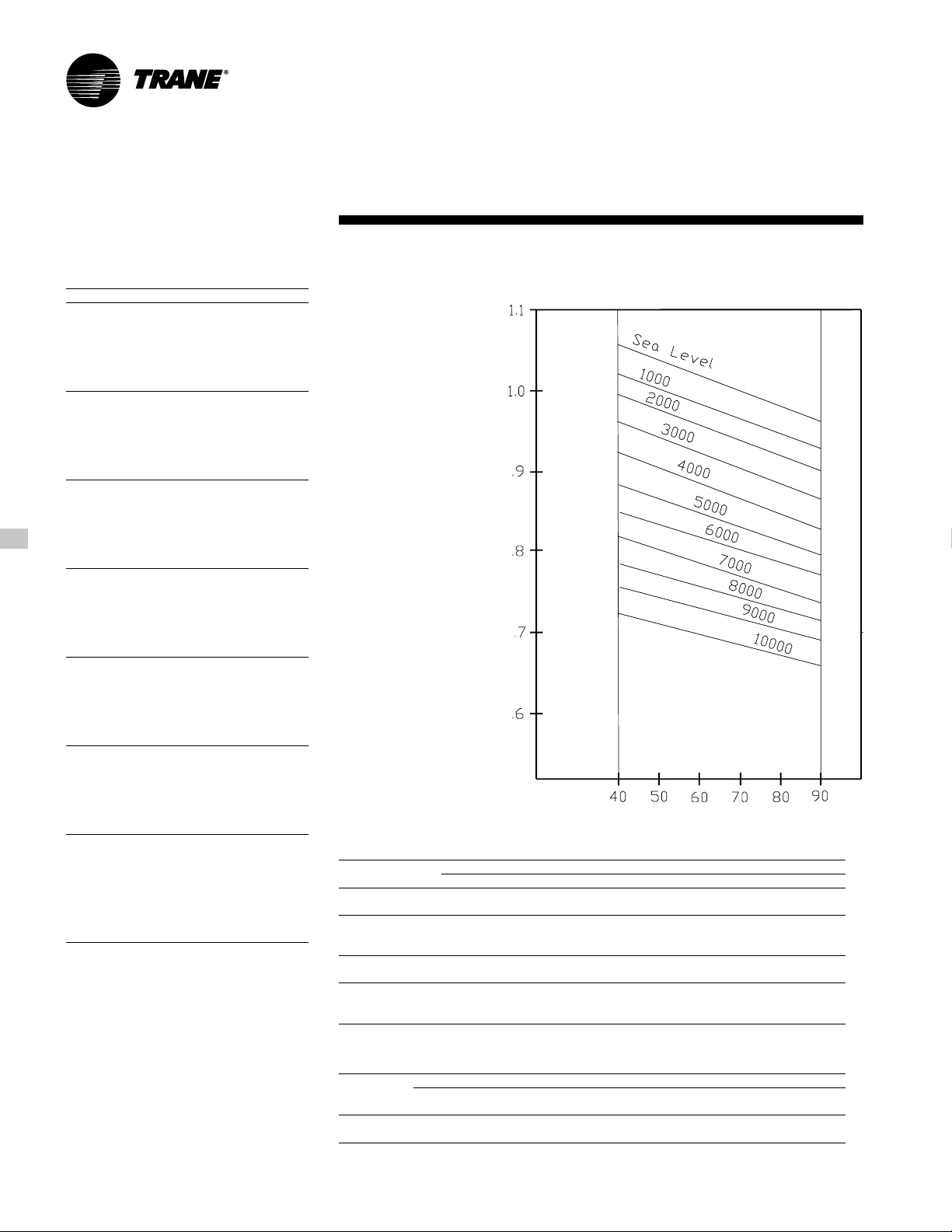
P erformance
Adjustment
Factors
Table PAF-1 — Enthalpy of Satur ated AIR
Wet Bulb Temperature Btu Per Lb.
40 15.23
41 15.70
42 16.17
43 16.66
44 17.15
45 17.65
46 18.16
47 18.68
48 19.21
49 19.75
50 20.30
51 20.86
52 21.44
53 22.02
54 22.62
55 23.22
56 23.84
57 24.48
58 25.12
59 25.78
60 26.46
61 27.15
62 27.85
63 28.57
64 29.31
65 30.06
66 30.83
67 31.62
68 32.42
69 33.25
70 34.09
71 34.95
72 35.83
73 36.74
74 37.66
75 38.61
Figure PAF-1 — Air Density Ratios
Altitude/Temperature Correction
Air Density
Ratio (Density
at New
Air Density)
Condition/Std.
Rooftop Leaving Air Temperature (degrees F)
Table PAF-2 — Cooling Capacity Altitude Correction Factors
Cooling Capacity
Multiplier 1 .00 0.99 0.99 0.98 0.97 0.96 0.95 0.94
KW Correction
Multiplier
(Compressors) 1.00 1.01 1.02 1.03 1.04 1.05 1.06 1.07
SHR Correction
Multiplier 1 .00 .98 .95 .93 .91 .89 .87 .8 5
Maximum
Condenser
Ambient 11 5 F 1 14 F 113 F 112 F 111 F 11 0 F 109 F 108 F
Note:
SHR = Sensible Heat Ratio
Sea Level 1000 2000 3000 4000 5000 6000 7000
Altitude (Ft.)
Table PAF-3 — Gas Heating Capacity Altit ude Cor r ection Factors
Sea Level 2001 2501 3501 4501 5501 6501
Capacity
Multiplier 1.00 .92 .88 .84 .80 . 7 6 .72
Note:
Correction factors are per AGA Std 221.30 — 1964, Part VI, 6.12. Local codes may supersede.
To 2000 To 2500 To 3500 To 4500 To 5500 To 6500 To 7500
Altitude (Ft.)
RT-PRC010-EN28
Page 29
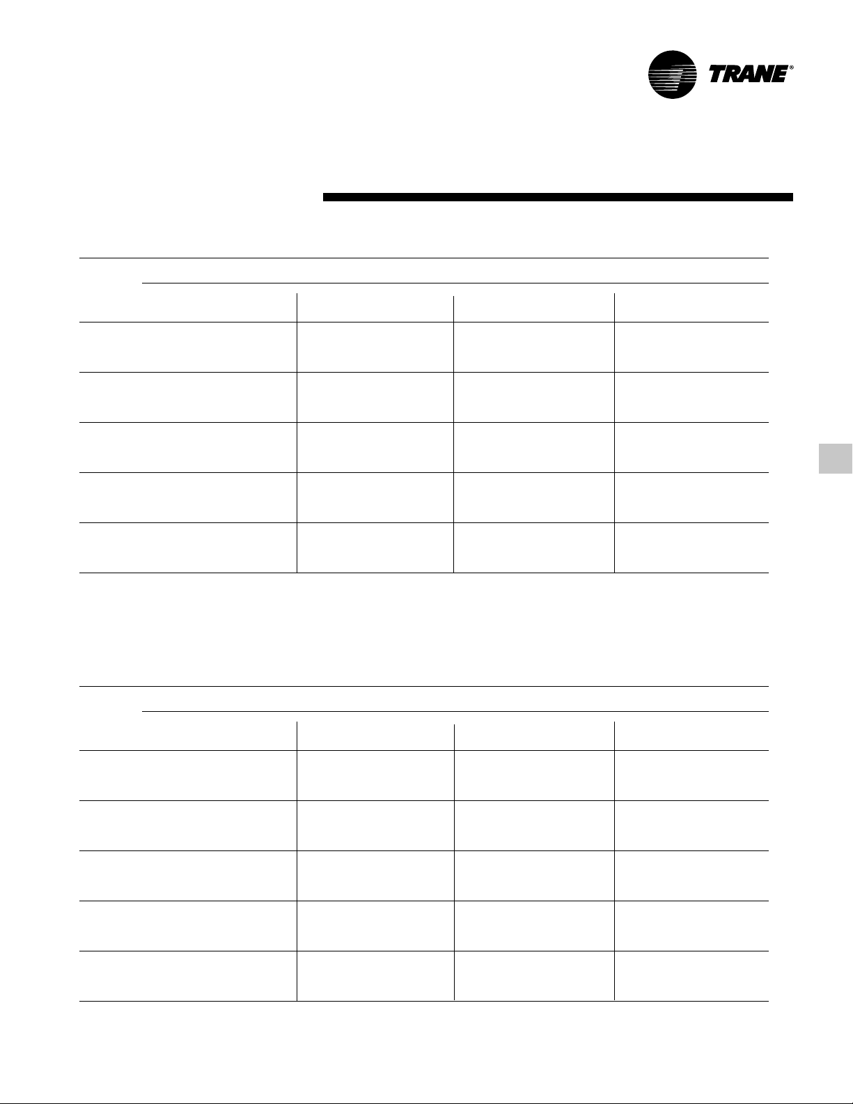
P erformance
(20 Ton)
Data
Table PD-1 — 20 T on Gr oss Cooling Capacities (MBh) — STANDARD CAP A CITY Ev apor a tor Coil With Scroll Compressor
Ambient T emperature
ENT Entering Wet Bulb
DB 61 67 73 61 67 73 61 67 73 61 67 73
CFM (F) CAP SHC CAP SHC CAP SHC CAP SHC CAP SHC CAP SHC CAP SHC CAP SHC CAP SHC CAP SHC CAP SHC CAP SHC
75 194 140 215 1 16 239 89 187 136 208 1 12 231 86 180 133 200 109 222 82 173 128 192 105 213 79
4000 80 194 159 216 135 239 111 188 155 208 132 231 108 181 151 201 128 222 103 173 147 192 124 213 99
85 195 178 216 154 239 130 189 174 209 151 231 126 182 170 201 147 222 122 175 166 192 143 213 1 18
90 196 196 216 173 239 149 191 191 209 169 231 145 185 185 201 165 223 141 179 179 193 161 213 137
75 214 166 236 133 261 96 206 162 228 129 251 93 198 158 218 125 241 89 189 154 208 121 230 85
6000 80 215 193 236 160 261 125 207 190 228 156 251 121 199 185 219 152 241 117 1 90 181 209 147 230 113
85 218 218 237 186 261 152 212 212 228 182 252 148 205 205 219 178 241 144 197 197 210 173 231 140
90 229 229 238 213 262 178 223 223 230 209 252 175 215 215 221 205 242 170 208 208 212 201 231 166
75 220 178 243 140 268 99 212 174 234 136 257 95 203 169 224 132 247 92 1 94 165 214 127 235 88
7000 80 222 209 243 170 268 131 214 205 234 166 258 127 206 201 224 162 247 123 197 197 214 157 235 119
85 229 229 244 200 268 162 222 222 235 196 258 158 215 215 225 192 247 154 207 207 215 188 236 149
90 241 241 246 231 269 192 234 234 238 228 259 188 226 226 229 223 248 183 218 218 219 219 237 179
75 225 189 248 146 273 101 216 185 239 142 262 98 207 180 228 138 251 94 198 176 217 134 239 90
8000 80 228 224 249 180 273 136 220 220 239 176 263 133 211 211 229 172 251 129 203 203 218 167 240 124
85 239 239 250 214 273 171 231 231 240 210 263 167 223 223 231 206 252 162 215 215 220 201 240 158
90 251 251 253 249 274 204 243 243 243 243 264 200 235 235 235 235 253 196 226 226 226 226 241 191
75 229 199 252 152 277 104 221 195 242 148 266 100 211 190 232 144 255 96 202 186 221 139 242 92
9000 80 234 234 253 189 277 142 226 226 243 185 266 138 218 218 233 181 255 134 209 209 222 176 243 130
85 246 246 254 227 278 179 239 239 245 223 267 175 230 230 235 218 256 171 221 221 224 214 244 166
90 259 259 259 259 279 216 251 251 251 251 268 212 242 242 242 242 256 207 233 233 233 233 244 203
85 95 105 115
Table PD-2 — 20 Ton Gross Cooling Capacities (Mbh) — HIGH CAP ACITY Evaporator Coil With Scroll Compressor
ENT Entering Wet Bulb
DB 61 67 73 61 67 73 61 67 73 61 67 73
CFM (F) CAP SHC CAP SHC CAP SHC CAP SHC CAP SHC CAP SHC CAP SHC CAP SHC CAP SHC CAP SHC CAP SHC CAP SHC
75 216 158 240 129 265 100 208 153 231 125 256 96 200 149 222 121 245 91 191 144 212 11 6 234 87
4000 80 217 180 240 152 265 123 209 176 231 148 256 118 201 171 222 143 245 1 1 4 192 166 212 139 234 1 1 0
85 218 203 240 174 266 145 211 198 232 170 256 141 202 194 222 166 246 137 194 189 213 161 235 132
90 222 222 241 196 266 167 216 216 232 192 256 163 209 209 223 187 246 159 201 201 213 183 235 154
75 238 190 262 150 288 106 228 186 251 145 277 102 219 181 241 141 264 97 208 176 229 136 252 93
6000 80 240 223 262 182 289 140 231 219 252 177 277 136 221 214 241 172 265 131 211 209 229 167 252 127
85 247 247 263 214 289 172 239 239 253 209 278 168 231 231 242 204 265 163 222 222 231 199 253 158
90 260 260 266 247 289 204 251 251 256 242 278 200 243 243 245 237 266 195 233 233 235 232 253 190
75 245 205 268 158 295 109 235 200 258 154 283 104 225 196 246 149 270 100 214 190 234 144 257 95
7000 80 248 244 269 195 296 148 238 238 258 190 284 144 229 229 247 186 271 139 220 220 235 180 257 134
85 260 260 271 233 296 185 251 251 260 228 284 180 242 242 249 223 271 175 232 232 238 218 258 170
90 273 273 275 271 297 221 264 264 264 264 285 217 254 254 254 254 273 212 244 244 244 244 259 207
75 250 220 274 168 301 1 11 240 215 262 164 288 107 230 210 251 159 274 102 219 205 238 154 260 98
8000 80 256 256 275 208 301 156 247 247 264 203 289 152 238 238 252 198 275 147 228 228 239 193 261 142
85 270 270 278 251 302 197 261 261 267 246 289 192 251 251 255 241 276 187 241 241 243 236 262 182
90 284 284 284 284 303 238 275 275 275 275 291 233 265 265 264 264 278 228 254 254 253 253 264 223
75 255 234 278 175 305 114 245 229 266 171 292 109 234 224 254 166 278 105 223 219 241 161 264 100
9000 80 264 264 279 221 306 164 255 255 268 216 293 159 245 245 256 211 279 155 235 235 243 206 265 150
85 279 279 283 269 306 208 269 269 272 264 293 203 259 259 260 259 280 198 248 248 248 248 266 193
Notes:
1. All capacities shown are gross and have not considered indoor fan heat.
2. CAP = Total gross cooling capacity (MBH).
3. SHC = Sensible heat capacity (MBH).
90 294 294 294 294 308 254 284 284 284 284 296 249 273 273 273 273 283 244 261 261 261 261 269 239
85 95 105 115
Ambient T emperature
29RT-PRC010-EN
Page 30
P erformance
(25 Ton)
Data
Table PD-3 — 25 Ton Gross Cooling Capacity — STANDARD CAPA CIT Y Ev apor ator Coil With Scroll Compressor
Ambient T emperature
ENT Entering Wet Bulb
DB 61 67 73 61 67 73 61 67 73 61 67 73
CFM (F) CAP SHC CAP SHC CAP SHC CAP SHC CAP SHC CAP SHC CAP SHC CAP SHC CAP SHC CAP SHC CAP SHC CAP SHC
75 245 179 272 148 301 112 237 175 263 143 290 107 228 170 253 139 279 103 219 165 242 134 267 98
5000 80 246 205 272 173 301 141 238 200 263 169 290 137 229 195 253 164 279 130 220 190 243 159 267 125
85 248 230 273 198 301 165 240 226 263 194 290 161 231 221 254 189 279 156 223 216 243 184 267 151
90 253 253 273 223 301 190 246 246 264 218 291 186 238 238 254 214 279 181 230 230 244 209 267 176
75 265 207 292 164 320 118 255 202 281 160 308 114 245 197 270 155 295 109 234 192 258 150 281 104
7000 80 267 241 293 198 320 154 258 237 282 194 308 149 248 232 270 188 295 144 237 226 258 183 281 139
85 272 272 293 232 321 188 264 264 282 227 309 183 255 255 271 221 296 178 246 246 259 216 282 173
90 285 285 295 266 321 221 277 277 285 261 309 216 268 268 274 255 296 211 258 258 262 250 282 205
75 276 228 303 177 331 122 266 223 291 172 318 1 18 255 218 279 167 304 113 243 213 266 162 289 108
8750 80 280 271 303 218 331 164 270 266 292 212 318 160 258 258 279 207 304 155 248 248 266 201 289 149
85 291 291 305 258 331 205 282 282 293 253 318 200 272 272 281 247 304 195 261 261 268 242 289 189
90 305 305 309 299 331 245 295 295 298 294 318 240 285 285 285 285 305 234 274 274 273 273 290 228
75 282 243 308 186 336 125 271 237 296 180 322 121 260 232 283 175 308 116 248 226 270 169 293 1 10
10000 80 286 286 309 230 336 171 277 277 297 225 322 167 267 267 284 219 308 162 256 256 271 214 293 156
85 30 1 301 311 275 336 216 291 291 299 270 323 21 1 281 281 287 265 308 206 269 269 274 259 293 200
90 316 316 315 315 337 260 305 305 305 305 323 255 294 294 294 294 309 250 282 282 282 282 294 244
75 286 253 312 192 339 128 275 248 299 186 325 123 264 243 286 181 311 117 252 237 272 175 295 112
11000 80 293 293 313 240 339 177 283 283 300 234 326 172 273 273 287 229 311 167 261 261 273 223 295 161
85 308 308 315 289 340 225 298 298 303 284 326 220 287 287 291 278 311 214 275 275 277 272 296 208
90 323 323 323 323 340 273 312 312 312 312 327 267 300 300 300 300 312 262 288 288 287 287 297 256
85 95 105 115
Table PD-4 — 25 Ton Gross Cooling Capacity — HIGH CAPACITY Evaporat or Coil With Scroll Compressor
Ambient T emperature
ENT Entering Wet Bulb
DB 61 67 73 61 67 73 61 67 73 61 67 73
CFM (F) CAP SHC CAP SHC CAP SHC CAP SHC CAP SHC CAP SHC CAP SHC CAP SHC CAP SHC CAP SHC CAP SHC CAP SHC
75 273 273 303 163 334 125 263 194 291 158 322 120 253 188 280 153 309 115 242 182 267 147 296 1 10
5000 80 274 226 303 191 334 155 264 221 292 186 322 150 254 215 280 180 310 145 243 209 268 17 4 296 139
85 277 255 304 219 334 184 267 249 292 214 323 179 257 244 281 209 310 174 246 238 268 202 296 168
90 283 283 305 246 334 210 275 275 294 241 323 205 266 266 282 235 310 200 257 257 270 229 297 194
75 295 235 325 185 355 131 283 230 312 179 342 126 271 223 299 173 328 121 259 217 285 168 313 1 15
7000 80 298 275 325 226 355 171 287 270 313 220 342 167 275 264 299 214 328 161 263 257 285 208 313 156
85 307 307 327 264 355 212 297 297 315 258 342 207 286 286 302 252 328 202 275 275 288 246 313 196
90 322 322 330 304 355 247 312 312 318 298 343 245 301 301 306 292 329 240 290 290 292 286 314 234
75 308 262 336 200 365 135 296 256 323 195 351 130 283 250 309 189 337 125 269 244 294 184 321 119
8750 80 314 313 337 248 365 185 302 302 324 243 352 180 290 290 310 237 337 175 279 279 296 231 321 170
85 329 329 340 297 365 236 318 318 327 292 352 230 307 307 314 286 337 223 294 294 300 280 322 217
90 344 344 344 344 367 281 333 333 333 333 353 275 322 322 322 322 339 270 309 309 309 309 324 264
75 315 281 342 211 370 137 302 275 328 206 356 133 289 269 314 200 341 127 276 262 299 193 325 122
10000 80 324 324 343 265 370 195 313 313 330 260 357 190 301 301 316 254 342 185 288 288 301 247 326 180
85 340 340 347 321 371 248 329 329 334 315 357 243 317 317 321 309 342 237 304 304 306 303 326 231
90 356 356 356 356 372 303 345 345 345 345 359 297 332 332 332 332 344 291 319 319 319 319 329 285
75 320 296 345 220 374 140 307 290 332 215 360 135 294 283 317 207 344 130 280 277 302 201 328 124
11000 80 331 331 347 278 374 203 320 320 334 273 360 198 308 308 320 267 345 193 295 295 305 260 328 187
85 348 348 352 339 375 259 337 337 339 333 360 254 324 324 324 324 345 249 311 311 31 1 311 329 243
Notes
1. All capacities shown are gross and have not considered indoor fan heat.
2. CAP = Total gross cooling capacity.
3. SHC = Sensible heat capacity.
90 364 364 364 364 376 318 352 352 352 352 362 313 339 339 339 339 348 308 326 326 326 326 332 302
85 95 105 115
RT-PRC010-EN30
Page 31

P erformance
(30 Ton)
Data
Table PD-5 — 30 T on Gr oss Cooling Capacity — STANDARD CAP A CITY Ev apor at or Coil With Scroll Compressor
Ambient T emperature
ENT Entering Wet Bulb
DB 61 67 73 61 67 73 61 67 73 61 67 73
CFM (F) CAP SHC CAP SHC CAP SHC CAP SHC CAP SHC CAP SHC CAP SHC CAP SHC CAP SHC CAP SHC CAP SHC CAP SHC
75 312 230 346 188 382 142 301 224 333 182 368 137 289 218 320 176 353 131 276 211 306 170 337 125
6000 80 313 264 346 222 382 178 302 257 334 216 368 172 290 251 320 210 353 166 278 244 306 203 337 160
10500 80 357 355 384 282 418 212 343 343 369 276 402 206 330 330 353 269 384 199 317 317 336 262
12000 80 368 368 391 300 425 222 355 355 376 294 408 216 342 342 359 287 390 209 327 327 342 279
13500 80 378 378 397 318 430 232 365 365 381 311 412 225 351 351 364 304 394 218 336 336 347 296
85 316 298 347 255 382 211 305 292 334 249 368 205 294 285 321 242 353 199 282 279 307 236 338 193
90 324 324 348 288 382 245 315 315 336 282 368 239 305 305 323 275 354 233 294 294 309 269 338 226
75 341 277 375 216 410 151 328 270 360 210 394 145 314 263 345 204 376 139 299 256 329 197 358 133
9000 80 345 326 376 264 410 201 333 320 361 257 394 195 319 313 346 250 377 189 304 304 329 243 359 182
85 357 357 378 311 411 250 346 346 363 305 394 243 334 334 348 298 377 236 321 321 332 291 359 229
90 375 375 382 360 411 296 363 363 368 354 395 289 350 350 353 347 378 283 336 336 336 336 361 276
75 351 298 384 229 418 155 337 291 368 222 401 149 322 284 352 215 383 143 307 277 335 208
85 374 374 387 338 419 266 361 361 372 331 402 260 348 348 357 324 385 253 334 334 340 317
90 392 392 392 392 420 320 379 379 379 379 404 313 365 365 365 365 386 306 350 350 350 350
75 359 318 390 240 424 158 344 311 374 233 407 152 329 304 358 226 389 146 314 297 340 219
85 387 387 395 363 425 282 374 374 380 356 408 276 359 359 364 349 390 269 345 345 347 342
90 406 406 406 406 427 342 392 392 392 392 410 336 377 377 377 377 392 329 362 362 361 361
75 365 338 395 250 429 162 351 331 379 244 412 156 336 323 362 237 393 150 320 316 344 229
85 398 398 403 387 431 297 384 384 387 380 413 291 369 369 369 369 394 284 353 353 353 353
90 417 417 417 417 433 365 402 402 402 402 416 358 387 387 387 387 397 351
85 95 105 115
Table PD-6 — 30 T on Gr oss Cooling Capacity — HIGH CAPACITY Evapor at or Coil With Scroll Compressor
Ambient T emperature
ENT Entering Wet Bulb
DB 61 67 73 61 67 73 61 67 73 61 67 73
CFM (F) CAP SHC CAP SHC CAP SHC CAP SHC CAP SHC CAP SHC CAP SHC CAP SHC CAP SHC CAP SHC CAP SHC CAP SHC
75 324 237 358 194 395 148 312 230 345 188 381 142 299 224 331 181 365 136 285 219 316 174 349 129
6000 80 325 269 359 229 395 183 313 263 345 223 381 177 300 260 331 216 365 171 287 253 316 210 349 164
85 328 304 360 261 395 218 316 297 346 254 381 212 304 296 332 248 366 206 291 289 317 240 350 199
90 337 337 361 294 396 250 327 327 348 287 381 244 316 316 334 280 366 237 304 304 319 273 350 230
75 354 289 388 225 423 156 340 284 373 218 407 150 325 277 357 211 389 144 310 267 339 204
9000 80 359 341 389 275 423 208 345 334 374 268 407 202 331 327 358 261 390 196 315 315 341 254
85 372 372 391 325 424 260 360 360 376 319 408 254 347 347 361 312 390 247 333 333 344 304
90 390 390 396 377 424 308 378 378 381 370 409 302 364 364 366 363 391 295 350 350 350 350
10500 80 370 370 398 295 431 220 357 357 382 289 415 214 344 344 366 282 397 207 329 329 349 274
12000 80 384 384 405 315 437 232 370 370 389 309 420 226 356 356 372 301 402 219 341 341 355 294
13500 80 394 394 411 335 442 243 380 380 395 328 425 237 366 366 378 321 406 231 350 350 360 313
Notes:
1. All capacities shown are gross and have not considered indoor fan heat.
2. CAP = Total gross cooling capacity.
3. SHC = Sensible heat capacity.
75 364 312 397 239 431 159 349 305 381 231 414 153 334 297 365 224 396 147 318 290 347 217
85 389 389 401 354 432 278 376 376 386 347 415 271 362 362 370 340 397 264 348 348 353 333
90 408 408 408 408 433 334 394 394 394 394 417 328 380 380 380 380 399 321
75 373 335 403 253 437 162 357 332 387 246 420 157 342 325 370 240 402 150 325 312 352 233
85 403 403 410 382 438 299 389 389 394 375 421 292 375 375 378 368 403 286 359 359 361 361
90 422 422 422 422 440 360 408 408 408 408 424 353 392 392 392 392 406 346
75 380 357 408 266 442 166 364 349 392 257 425 160 348 342 375 248 406 154 330 330 356 241
85 414 414 417 409 443 312 400 400 400 400 426 306 384 384 384 384 407 299
90 433 433 433 433 446 385 418 418 418 418 429 378 403 403 403 403 411 371
85 95 105 115
31RT-PRC010-EN
Page 32

P erformance
(40 Ton)
Data
Table PD-7 — 40 Ton Gross Cooling Capacity — STANDARD CAPA CITY Evaporator Coil With Scroll Compressor
Ambient T emperature
ENT Entering Wet Bulb
DB 61 67 73 61 67 73 61 67 73 61 67 73
CFM (F) CAP SHC CAP SHC CAP SHC CAP SHC CAP SHC CAP SHC CAP SHC CAP SHC CAP SHC CAP SHC CAP SHC CAP SHC
75 395 289 438 237 483 179 382 282 423 230 467 173 367 274 407 223 448 166 352 265 389 215 429 158
8000 80 396 329 438 278 483 226 383 322 423 271 466 220 368 314 407 264 448 210 353 306 390 256 429 202
85 399 371 439 319 483 265 386 364 424 312 467 258 372 356 408 304 449 251 358 348 390 295 429 243
90 406 406 439 359 484 306 395 395 425 352 467 299 383 383 409 344 449 291 370 370 392 335 430 283
75 425 331 468 263 514 189 409 323 451 255 495 182 393 315 432 247 474 175 375 306 413 239 452 167
11000 80 428 385 469 317 514 246 413 377 451 309 495 239 397 369 433 301 474 231 380 360 413 292 452 222
85 435 435 470 370 515 300 422 422 453 362 496 293 408 408 434 353 475 285 393 393 415 344 453 276
90 456 456 473 423 515 353 443 443 457 415 496 345 428 428 439 407 476 337 412 412 420 398 454 328
75 443 367 487 285 533 197 427 359 468 277 512 190 410 351 448 269 490 183 391 342 427 260 466 174
14000 80 450 435 488 350 533 265 434 428 469 342 512 257 415 415 449 333 490 249 399 399 428 324 467 241
85 468 468 490 415 533 331 453 453 472 407 513 323 437 437 452 398 491 314 420 420 431 389 468 305
90 490 490 497 482 535 395 475 475 479 474 514 386 458 458 458 458 492 378 440 440 440 440 469 369
75 453 390 496 299 542 203 436 382 476 290 521 195 418 373 455 282 498 187 399 364 434 272 473 178
16000 80 460 460 497 370 542 277 445 445 478 362 521 269 429 429 457 353 498 261 412 412 435 344 474 252
85 484 484 500 443 543 349 469 469 482 435 522 341 452 452 462 426 499 332 433 433 440 417 475 323
90 508 508 508 508 544 420 492 492 491 491 523 412 474 474 474 474 501 403 455 455 455 455 477 394
75 462 412 503 311 549 207 444 403 483 302 527 200 425 394 462 293 504 192 406 385 439 284 479 181
18000 80 473 473 504 389 549 288 458 458 484 381 528 280 441 441 463 372 504 272 422 422 441 363 479 263
85 498 498 509 470 550 367 482 482 490 462 529 358 464 464 470 453 505 350 445 445 448 444 480 340
90 523 523 523 523 552 445 506 506 505 505 531 437 487 487 487 487 508 428 467 467 467 467 483 419
85 95 105 115
Table PD-8 — 40 Ton Gross Cooling Capacity — HIGH CAPACITY Evaporat or Coil With Scroll Compressor
Ambient T emperature
ENT Entering Wet Bulb
DB 61 67 73 61 67 73 61 67 73 61 67 73
CFM (F) CAP SHC CAP SHC CAP SHC CAP SHC CAP SHC CAP SHC CAP SHC CAP SHC CAP SHC CAP SHC CAP SHC CAP SHC
75 436 321 483 261 533 199 420 313 465 253 514 192 403 304 446 244 493 183 385 294 426 235 471 174
8000 80 438 367 484 309 533 247 422 359 466 300 514 239 405 350 447 291 493 230 387 340 427 282 471 222
85 442 415 485 351 534 294 426 406 467 347 515 286 410 397 448 338 494 277 392 388 427 328 472 268
90 453 453 486 401 534 341 439 439 469 393 515 333 425 425 450 383 494 319 409 409 430 374 472 314
75 469 372 517 293 566 208 451 365 497 284 544 200 432 355 475 275 521 192 411 345 452 265 496 183
11000 80 474 436 518 357 566 273 456 427 498 349 544 264 437 417 476 340 521 256 418 407 453 328 497 247
85 487 487 520 420 567 337 471 471 500 408 545 328 454 454 479 399 522 320 436 436 457 388 498 310
90 511 511 525 480 567 400 495 495 506 471 546 391 478 478 485 462 523 382 459 459 464 452 499 369
75 491 419 536 320 585 216 472 409 515 311 561 207 451 399 493 302 537 199 429 389 468 292 511 190
14000 80 501 501 538 397 585 297 482 482 517 388 562 289 463 463 495 378 538 280 444 444 471 368 512 271
85 525 525 542 475 586 374 507 507 522 466 563 365 489 489 500 456 538 355 469 469 477 446 512 346
90 550 550 550 550 588 450 532 532 532 532 566 441 513 513 513 513 541 432 492 492 492 492 516 422
75 503 449 545 337 594 220 483 440 524 329 570 212 461 429 500 320 544 203 439 419 476 310 518 194
16000 80 517 517 548 424 594 313 499 499 526 415 571 304 480 480 504 405 545 296 459 459 479 395 519 286
85 544 544 555 513 595 397 525 525 533 503 571 389 506 506 51 1 494 546 379 485 485 487 484 520 369
90 570 570 570 570 599 484 551 551 551 551 575 475 531 531 531 531 551 466 509 509 509 509 524 456
75 512 478 553 355 601 225 492 469 531 346 576 216 470 458 507 337 550 208 445 445 481 327 523 199
18000 80 532 532 556 450 601 328 513 513 534 441 577 320 494 494 511 431 551 311 472 472 486 420 524 302
85 560 560 565 549 602 421 540 540 544 540 579 412 520 520 519 519 553 402 498 498 497 497 526 392
Notes:
1. All capacities shown are gross and have not considered indoor fan heat.
2. CAP = Total gross cooling capacity.
3. SHC = Sensible heat capacity.
90 587 587 587 587 607 517 567 567 567 567 584 508 545 545 545 545 559 499 522 522 522 522 532 489
85 95 105 115
RT-PRC010-EN32
Page 33

P erformance
(50 Ton)
Data
Table PD-9 — 50 Ton Gross Cooling Capacity — ST ANDARD CAP ACIT Y Ev aporat or Coil With Scroll Compressor
Ambient T emperature
ENT Entering Wet Bulb
DB 61 67 73 61 67 73 61 67 73 61 67 73
CFM (F) CAP SHC CAP SHC CAP SHC CAP SHC CAP SHC CAP SHC CAP SHC CAP SHC CAP SHC CAP SHC CAP SHC CAP SHC
75 521 382 578 313 638 238 502 372 557 304 615 229 483 362 536 294 591 219 462 351 513 283 566 209
10000 80 523 437 579 369 638 297 504 427 558 359 615 288 485 416 536 349 591 278 465 406 514 338 566 268
85 527 493 579 423 639 352 509 483 559 413 616 342 491 473 537 403 592 332 471 462 515 392 566 322
90 539 539 581 477 639 407 524 524 561 467 617 397 507 507 540 457 593 387 490 490 517 446 567 376
75 562 443 620 352 680 250 541 433 597 341 654 241 519 422 572 331 626 231 496 410 546 320 597 221
14000 80 568 519 621 425 680 328 547 508 598 414 654 318 525 497 573 403 627 307 503 486 547 391 598 297
85 581 581 623 497 681 402 563 563 600 487 655 392 544 544 576 475 628 382 524 524 550 464 598 370
90 610 610 628 572 681 474 591 591 606 561 656 464 571 571 582 550 629 452 550 550 557 538 600 441
75 586 492 642 391 701 259 563 481 617 381 674 250 540 469 590 369 645 240 515 457 563 358 614 229
17500 80 596 585 644 467 702 352 575 574 619 456 674 342 551 551 592 445 645 331 529 529 565 433 615 320
85 622 622 648 556 702 441 602 602 623 545 675 430 580 580 597 534 646 419 557 557 570 522 616 407
90 652 652 658 648 704 527 631 631 631 631 677 517 609 609 608 608 648 505 585 585 585 585 618 494
75 599 524 654 398 712 265 576 513 627 387 684 256 552 501 600 375 654 246 527 489 572 363 622 235
20000 80 612 612 656 496 713 368 592 592 630 485 685 358 570 570 602 473 655 347 547 547 574 461 623 336
85 644 644 661 596 714 466 622 622 636 585 686 455 599 599 609 573 656 444 575 575 582 561 624 432
90 675 675 675 675 716 564 653 653 653 653 688 553 629 629 629 629 658 541 604 604 604 604 627 529
75 610 554 663 415 721 271 587 543 636 403 692 262 562 531 608 392 661 251 536 519 579 380 629 240
22500 80 629 629 665 523 722 383 608 608 639 512 693 373 585 585 61 1 500 662 363 561 561 582 488 630 350
85 662 662 673 634 722 490 640 640 647 623 694 479 616 616 620 612 663 468 590 590 590 590 631 456
90 694 694 694 694 723 598 671 671 671 671 697 587 646 646 646 646 667 576 619 619 619 619 635 564
85 95 105 115
Table PD-10 — 50 Ton Gr oss Cooling Capacity — HIGH CAPACITY Evaporator Coil With Scroll Compressor
ENT Entering Wet Bulb
DB 61 67 73 61 67 73 61 67 73 61 67 73
CFM (F) CAP SHC CAP SHC CAP SHC CAP SHC CAP SHC CAP SHC CAP SHC CAP SHC CAP SHC CAP SHC CAP SHC CAP SHC
75 540 397 598 324 660 247 520 387 577 314 637 237 500 376 554 303 612 227 478 365 529 292 585 217
10000 80 542 455 599 382 660 306 522 444 577 372 637 296 502 433 554 361 612 286 480 422 530 350 586 276
85 547 514 600 440 660 365 528 503 578 429 637 355 508 492 555 419 613 344 487 481 531 407 586 333
90 560 560 602 497 661 421 544 544 581 486 638 41 1 526 526 558 475 613 401 508 508 534 463 587 390
75 582 463 642 366 701 258 560 452 617 356 675 248 537 440 591 345 647 238 512 428 564 333 618 228
14000 80 589 544 643 443 701 340 567 532 619 433 675 330 544 521 592 420 648 320 520 509 565 408 618 309
85 605 605 645 520 702 417 586 586 622 509 676 407 565 565 596 498 648 396 544 544 569 486 619 385
90 635 635 651 599 703 495 616 616 628 588 677 484 595 595 604 577 649 473 572 572 578 565 621 461
75 608 517 663 395 722 266 584 505 638 385 695 257 559 493 611 374 665 246 533 480 582 362 634 236
17500 80 620 617 665 489 723 368 595 595 639 479 695 358 573 573 613 467 666 348 550 550 584 455 635 333
85 648 648 670 585 723 460 627 627 646 574 696 450 604 604 619 563 666 439 581 581 592 551 636 427
90 678 678 678 678 725 553 657 657 657 657 699 543 634 634 634 634 670 532 609 609 609 609 639 520
75 620 547 673 419 731 271 595 535 647 408 703 262 570 522 619 397 673 251 543 510 590 385 642 241
20000 80 634 634 675 516 731 384 613 613 649 505 704 372 590 590 622 494 674 359 566 566 593 481 643 348
85 667 667 682 622 732 484 645 645 657 61 1 704 474 621 621 631 600 675 462 597 597 603 587 643 451
90 698 698 698 698 732 858 676 676 676 676 708 576 651 651 651 651 679 565 626 626 626 626 648 553
22500 80 656 656 687 553 742 399 633 633 660 541 713 389 610 610 632 530 683 379 585 585 603 517 650 368
Notes:
1. All capacities shown are gross and have not considered indoor fan heat.
2. CAP = Total gross cooling capacity.
3. SHC = Sensible heat capacity.
75 634 588 683 435 741 278 609 576 656 424 712 268 582 563 628 412 682 258 555 551 598 400 649 247
85 689 689 697 673 743 516 666 666 671 662 714 506 641 641 641 641 684 495 615 615 615 615 652 483
90 721 721 721 721 747 633 698 698 698 698 719 623 672 672 672 672 690 612 645 645 645 645 658 600
85 95 105 115
Ambient T emperature
33RT-PRC01 0-EN
Page 34

P erformance
(55 Ton)
Data
Table PD-1 1 — 55 Ton Gross Cooling Capacity — STANDARD CAP A CITY Ev apor at or Coil With Scroll Compressor
Ambient T emperature
ENT Entering Wet Bulb
DB 61 67 73 61 67 73 61 67 73 61 67 73
CFM (F) CAP SHC CAP SHC CAP SHC CAP SHC CAP SHC CAP SHC CAP SHC CAP SHC CAP SHC CAP SHC CAP SHC CAP SHC
75 637 470 706 384 782 291 614 457 681 372 753 279 590 445 654 360 724 268 565 431 626 347 692 256
12000 80 639 537 707 453 782 365 617 525 682 441 753 354 593 512 655 428 723 342 568 499 627 415 692 327
85 646 608 708 520 782 432 624 596 683 508 754 420 601 583 656 495 724 408 577 570 628 481 693 395
90 662 662 710 587 783 501 643 643 686 575 755 489 623 623 659 562 726 476 601 601 632 549 694 463
75 679 532 750 423 827 305 654 519 722 411 795 293 627 505 692 398 762 281 599 491 660 385 726 268
16000 80 685 621 751 510 827 396 660 608 723 497 795 384 634 594 693 484 762 371 607 580 662 469 727 358
85 699 699 754 596 828 485 678 678 726 583 797 472 655 655 696 569 764 460 631 631 666 555 729 447
90 735 735 760 684 829 570 712 712 733 671 798 557 689 689 704 658 765 544 663 663 674 644 731 530
75 703 577 774 452 851 314 676 564 744 439 817 302 648 550 712 426 782 290 619 536 679 411
19250 80 713 683 776 551 852 420 688 670 746 538 818 408 661 656 714 524 783 395 631 631 681 510
85 741 741 780 653 852 523 717 717 750 639 819 510 692 692 720 626 784 496 665 665 687 611
90 779 779 791 757 855 622 754 754 762 744 822 609 728 728 733 730 787 595 700 700 700 700
75 719 614 790 472 866 321 691 600 757 458 831 309 662 586 724 445 795 297 632 571 690 430
22000 80 734 733 792 584 867 439 705 705 760 570 833 426 680 680 728 556 796 413 653 653 693 541
85 769 769 798 698 869 552 744 744 767 684 834 539 717 717 735 670 798 525 689 689 702 656
90 809 809 808 808 871 663 782 782 782 782 837 650 755 755 754 754 802 636 725 725 725 725
75 729 639 798 486 876 327 701 625 766 473 840 315 671 61 1 732 458 803 302 641 596 697 444
24000 80 746 746 801 606 877 452 721 721 769 593 841 439 694 694 736 578 804 426 666 666 701 564
85 787 787 809 730 879 573 760 760 778 716 843 559 733 733 746 702 806 545 703 703 712 687
90 827 827 827 827 882 693 800 800 800 800 847 679 771 771 771 771 811 665
85 95 105 115
Table PD-12 — 55 Ton Gross Cooling Capacity — HIGH CAP ACIT Y Ev apor ator Coil With Scroll Compressor
Ambient T emperature
ENT Entering Wet Bulb
DB 61 67 73 61 67 73 61 67 73 61 67 73
CFM (F) CAP SHC CAP SHC CAP SHC CAP SHC CAP SHC CAP SHC CAP SHC CAP SHC CAP SHC CAP SHC CAP SHC CAP SHC
75 655 472 724 394 796 296 631 460 697 381 768 285 606 446 669 368 737 273 579 432 639 355 704 260
12000 80 658 538 725 457 796 370 634 525 698 441 768 359 609 512 670 428 737 346 583 497 640 414 704 334
85 665 606 726 520 797 435 642 593 699 507 768 422 618 580 672 494 738 410 593 566 642 479 705 404
90 683 683 729 585 797 497 663 663 703 572 769 485 642 642 676 558 738 472 619 619 647 544 706 458
75 697 552 767 434 837 308 670 538 737 424 805 296 642 524 706 411 771 284 613 510 673 394 735 271
16000 80 705 647 768 527 837 405 679 633 738 514 805 393 652 619 707 501 771 381 623 605 674 486 736 367
85 722 722 771 619 837 496 699 699 743 606 806 483 675 675 712 592 772 470 649 649 680 577 736 457
90 758 758 779 681 838 588 735 735 751 699 807 576 709 709 721 685 773 561 682 682 690 671 738 547
19250 80 735 716 789 572 857 432 707 703 759 558 824 420 676 676 727 544 789 407 649 649 693 530
Notes:
1. All capacities shown are gross and have not considered indoor fan heat.
2. CAP = Total gross cooling capacity.
3. SHC = Sensible heat capacity.
75 722 603 788 463 857 316 693 589 758 450 824 304 664 574 725 437 788 291 633 560 691 423
85 765 765 796 681 858 537 739 739 766 667 825 525 713 713 734 653 790 512 684 684 701 639
90 800 800 808 792 860 644 774 774 779 779 828 631 747 747 746 746 793 617 717 717 717 717
75 738 644 802 487 870 322 709 630 770 473 836 310 679 615 737 460 799 298 647 600 701 446
22000 80 753 753 804 608 870 454 728 728 773 594 836 435 700 700 740 580 800 422 671 671 705 566
85 791 791 813 731 871 575 765 765 782 717 837 557 737 737 750 703 800 543 707 707 716 689
90 828 828 828 828 873 595 801 801 801 801 842 677 771 771 771 771 806 663 740 740 740 740
75 749 672 809 503 878 328 719 658 778 490 843 315 688 643 743 476 806 302 656 628 707 461
24000 80 770 770 813 633 878 462 743 743 781 620 843 449 715 715 748 606 806 436 685 685 712 591
85 808 808 823 767 879 594 780 780 792 753 844 580 751 751 759 739 807 566 720 720 725 724
90 845 845 845 845 885 723 817 817 817 817 850 709 787 787 786 786 814 695
85 95 105 11 5
RT-PRC010-EN34
Page 35

(60 Ton)P erformance
Data
Table PD-13 — 60 Ton Gr oss Cooling Capacity — S TANDARD CAP ACIT Y Ev apora tor Coil With Scroll Compressor
Ambient T emperature
ENT Entering Wet Bulb
DB 61 67 73 61 67 73 61 67 73 61 67 73
CFM (F) CAP SHC CAP SHC CAP SHC CAP SHC CAP SHC CAP SHC CAP SHC CAP SHC CAP SHC CAP SHC CAP SHC CAP SHC
75 617 467 683 379 754 279 596 456 659 367 726 268 573 444 633 355 696 257 549 431 605 343 664 245
14000 80 621 540 684 450 755 361 600 528 660 439 727 345 578 516 634 426 697 334 554 504 606 413 665 321
85 631 616 687 521 756 430 611 604 663 509 728 419 587 587 636 497 698 407 566 566 608 483 665 393
90 655 655 691 593 757 500 637 637 667 581 730 488 617 617 641 569 700 475 595 595 614 555 668 462
75 651 522 718 413 789 292 627 510 690 401 758 281 603 498 661 388 725 269 576 484 630 374 689 256
18000 80 659 614 721 500 790 386 636 603 693 488 759 374 612 590 664 475 726 362 586 577 633 461 690 349
85 680 680 723 588 792 475 659 659 697 576 761 463 637 637 668 563 727 449 612 612 637 549 692 435
90 715 715 732 680 794 562 693 693 705 667 763 549 669 669 678 654 729 535 643 643 648 640 693 521
75 670 560 736 434 807 300 645 548 708 422 775 288 619 535 677 409 739 276 591 521 645 395 702 263
21000 80 682 666 739 534 809 406 658 654 710 521 776 394 630 630 680 508 741 381 605 605 647 494 703 368
85 712 712 744 635 811 505 689 689 715 623 778 493 664 664 685 609 743 479 638 638 654 595 705 464
90 748 748 756 740 813 604 724 724 729 728 780 591 698 698 698 698 745 577 669 669 669 669 707 562
75 685 596 751 454 821 307 660 583 721 442 787 296 632 570 689 428 751 284 603 556 655 414 711 270
24000 80 699 699 754 566 823 424 676 676 724 553 789 412 651 651 692 539 751 398 625 625 658 524 712 383
85 737 737 760 680 825 534 713 713 731 667 791 521 687 687 700 653 754 507 658 658 667 638 715 492
90 775 775 775 775 827 645 749 749 749 749 793 631 721 721 721 721 757 617 690 690 690 690 718 602
75 698 629 762 473 832 314 672 616 731 460 797 301 643 603 699 446 759 288 613 588 664 432 719 275
27000 80 720 720 765 596 833 440 695 695 735 583 798 427 669 669 702 569 761 413 641 641 667 554 720 398
85 758 758 774 722 836 561 733 733 744 708 801 547 705 705 712 694 763 533 674 674 674 674 722 517
90 797 797 797 797 839 683 770 770 769 769 804 669 739 739 739 739 767 655 706 706 706 706 733 641
85 95 105 115
Table PD-14 — 60 Ton Gr oss Cooling Capacity — HIGH CAPACITY Ev aporat or Coil With Scroll Compressor
Ambient T emperature
ENT Entering Wet Bulb
DB 61 67 73 61 67 73 61 67 73 61 67 73
CFM (F) CAP SHC CAP SHC CAP SHC CAP SHC CAP SHC CAP SHC CAP SHC CAP SHC CAP SHC CAP SHC CAP SHC CAP SHC
14000 80 682 596 750 495 823 387 657 583 722 483 792 375 631 569 693 470 759 362 604 555 661 456 725 349
18000 80 724 684 785 556 856 420 697 670 755 543 823 408 669 656 723 529 788 395 638 638 689 514 751 381
21000 80 749 747 804 593 873 444 721 721 772 579 839 432 694 694 739 565 803 419 666 666 705 550 764 405
24000 80 772 772 819 632 887 467 746 746 787 619 851 455 718 718 752 604 813 442 688 688 717 589 774 428
27000 80 794 794 831 671 896 491 766 766 798 657 860 478 737 737 763 642 822 465 706 706 726 627 781 452
Notes:
1. All capacities shown are gross and have not considered indoor fan heat.
2. CAP = Total gross cooling capacity.
3. SHC = Sensible heat capacity.
75 676 514 749 413 822 305 651 503 721 400 792 293 625 488 691 387 758 280 597 474 660 374 724 267
85 692 680 752 574 823 469 668 667 724 561 793 457 643 643 695 547 760 444 620 620 664 532 726 430
90 721 721 757 654 824 551 699 699 730 641 794 535 676 676 701 627 761 522 652 652 670 612 726 508
75 714 579 784 453 856 315 686 571 753 440 823 303 658 552 721 427 787 290 628 537 687 413 750 277
85 750 750 790 653 857 524 725 725 760 639 824 512 700 700 729 625 789 499 672 672 695 610 751 484
90 786 786 799 755 859 625 761 761 770 742 826 606 734 734 740 728 792 592 706 706 705 705 754 578
75 735 626 802 481 872 322 706 612 770 468 838 310 676 597 737 455 802 297 645 582 701 441 763 284
85 784 784 811 709 874 565 758 758 780 696 839 550 730 730 747 681 803 530 701 701 713 666 765 516
90 822 822 822 822 878 671 795 795 795 795 843 657 767 767 766 766 807 643 735 735 735 735 769 629
75 752 670 815 505 885 330 722 656 782 489 850 317 691 641 748 475 813 304 659 626 712 460 773 290
85 812 812 828 765 888 492 785 785 797 751 851 579 755 755 764 736 814 565 724 724 728 721 775 550
90 851 851 850 850 892 721 822 822 822 822 856 707 792 792 792 792 819 693 759 759 758 758 780 678
75 765 713 826 527 895 336 736 699 792 520 859 323 704 684 757 498 821 310 671 668 720 490 780 297
85 835 835 843 818 897 627 806 806 812 805 861 613 775 775 775 775 823 599 742 742 742 742 783 584
90 876 876 876 876 922 776 844 844 844 844 876 759 811 81 1 811 811 830 742 777 777 777 777 790 727
85 95 105 115
35RT-PRC010-EN
Page 36

(70 Ton)P erformance
Data
Table PD-15 — 70 Ton Gross Cooling Capacity — STANDARD CAPA CITY Ev apor at or Coil
Ambient Temperature (F)
AIR- ENT Entering Wet Bulb (F)
FLOW DB 61 67 73 61 67 73 61 67 73 61 67 73
CFM (F) CAP SHC CAP SHC CAP SHC CAP SHC CAP SHC CAP SHC CAP SHC CAP SHC CAP SHC CAP SHC CAP SHC CAP SHC
75 742 558 824 449 913 327 708 538 786 430 872 308 672 517 747 410 829 289 635 495 707 390 785 269
16000 80 749 650 826 537 914 424 716 630 789 518 873 405 681 609 750 497 831 385 644 587 710 476 787 364
85 763 746 830 628 916 513 730 725 793 607 876 493 693 693 754 586 834 473 661 661 714 565 790 453
90 792 792 837 719 919 603 762 762 801 698 879 584 731 731 763 677 836 563 698 698 724 656 792 543
75 781 622 862 492 952 341 744 601 822 473 908 322 706 580 780 452 863 302 667 557 736 430 815 282
20000 80 793 736 864 596 954 460 757 715 824 575 910 435 719 693 783 554 865 415 681 671 740 532 818 394
85 815 815 872 706 957 567 783 783 832 685 913 547 749 749 792 664 868 526 714 714 749 642 821 505
90 859 859 884 819 960 676 826 826 846 798 917 655 792 792 806 776 872 634 755 755 764 754 826 612
75 796 652 877 503 967 347 758 631 835 482 922 328 720 609 793 462 875 308 679 587 748 440 827 288
22000 80 810 777 879 623 969 471 774 756 839 602 924 451 736 734 796 580 878 430 693 693 752 558 829 409
85 841 841 889 743 972 592 808 808 848 722 927 572 772 772 806 701 881 551 736 736 763 678 832 529
90 887 887 904 866 976 710 852 852 864 845 932 689 816 816 816 816 886 668 779 779 778 778 839 646
75 809 682 889 520 980 353 771 660 847 500 934 334 731 638 803 479 886 314 690 615 757 457 836 293
24000 80 826 817 893 649 982 486 783 783 851 628 936 466 748 748 808 606 889 445 71 1 711 763 584 839 424
85 864 864 903 780 985 617 829 829 862 758 939 596 793 793 820 736 891 574 755 755 775 714 842 552
90 911 911 922 913 991 743 875 875 875 875 946 722 838 838 838 838 899 701 799 799 799 799 851 679
75 821 710 899 537 990 359 782 688 856 517 944 339 742 666 812 495 895 319 700 643 765 472 844 298
26000 80 835 835 904 675 993 501 801 801 862 653 946 480 765 765 818 631 898 459 727 727 772 609 848 438
85 884 884 917 815 995 640 848 848 875 794 949 618 811 81 1 831 772 901 597 772 772 787 749 851 574
90 933 933 932 932 1003 776 896 896 895 895 958 755 857 857 857 857 910 733 817 817 817 817 861 711
75 826 724 904 546 995 361 787 702 861 525 948 342 747 680 816 503 899 322 705 657 768 480 848 301
27000 80 844 844 909 688 998 508 809 809 867 666 951 487 772 772 822 644 902 467 734 734 777 621 851 445
85 893 893 923 833 1000 651 857 857 881 81 1 954 630 819 819 837 789 905 608 779 779 792 766 855 585
Notes:
1. All capacities shown are gross and have not considered indoor fan heat.
2. CAP = Total Gross Cooling Capacity
3. SHC = Sensible Heat Capacity
90 943 943 942 942 1009 792 905 905 905 905 963 771 866 866 866 866 915 749 825 825 825 825 866 726
85 95 105 115
RT-PRC010-EN36
Page 37

P erformance
(75 Ton)
Data
Table PD-16 — 75 Ton Gr oss Cooling Capacity — STANDARD CAPACITY Evapora tor Coil
Ambient Temperature (F)
AIR- ENT Entering Wet Bulb (F)
FLOW DB 61 67 73 61 67 73 61 67 73 61 67 73
CFM (F) CAP SHC CAP SHC CAP SHC CAP SHC CAP SHC CAP SHC CAP SHC CAP SHC CAP SHC CAP SHC CAP SHC CAP SHC
75 767 576 853 462 946 340 731 555 814 441 903 320 694 533 773 421 858 300 656 51 1 731 399 811 279
16000 80 774 670 856 555 947 437 739 649 817 534 904 417 702 627 776 513 860 396 664 605 733 491 813 375
85 787 768 859 648 950 533 753 747 820 627 907 509 717 717 780 605 862 488 683 683 738 582 816 467
90 820 820 867 741 952 623 789 789 828 720 910 602 756 756 788 698 865 581 722 722 747 676 819 560
75 807 642 892 505 986 353 769 620 850 484 939 333 729 598 806 462 891 312 688 575 761 441 841 291
20000 80 819 760 895 616 988 473 781 738 853 594 942 453 742 715 809 572 894 432 702 692 764 549 844 410
85 846 846 902 729 991 592 812 812 861 707 945 565 776 776 818 685 897 543 739 739 773 662 848 521
90 891 891 914 845 994 698 856 856 874 823 949 676 820 820 832 801 902 654 782 782 788 778 853 631
75 823 674 907 525 1 000 359 783 652 863 504 953 339 743 629 818 483 904 318 701 606 772 461 853 297
22000 80 837 802 910 644 1 003 490 799 780 867 622 956 470 760 758 823 599 907 449 718 718 777 576 856 427
85 872 872 919 768 1006 612 837 837 877 746 959 591 800 800 833 723 910 570 762 762 787 700 859 546
90 920 920 934 895 101 0 733 884 884 893 873 964 712 846 846 845 845 916 689 806 806 806 806 866 666
75 837 704 919 545 1013 365 796 682 875 523 965 344 755 659 829 495 914 323 712 635 782 473
24000 80 854 844 923 671 1015 507 812 812 880 649 967 487 775 775 834 626 918 466 737 737 787 603
85 896 896 934 806 101 9 638 860 860 891 784 970 615 822 822 846 761 921 593 782 782 800 737
90 946 946 953 944 1024 768 908 908 908 908 977 746 868 868 868 868 928 724 827 827 827 827
75 849 734 930 556 1023 370 808 712 885 535 974 350 766 688 838 512 923 329 722 665 789 488
26000 80 867 867 935 698 1026 524 831 831 891 676 977 503 793 793 845 653 927 482 753 753 797 629
85 918 918 948 843 1029 661 880 880 904 821 980 639 840 840 858 798 930 616 799 799 811 774
90 968 968 968 968 1036 802 929 929 929 929 989 780 889 889 889 889 939 757 846 846 846 846
75 854 749 935 575 1028 373 813 726 889 554 979 352 771 703 841 529 927 331 727 679 793 506
27000 80 877 877 941 71 1 1031 532 839 839 895 689 982 504 80 1 801 849 666 931 483 760 760 801 642
85 928 928 954 862 1034 673 889 889 910 839 985 651 849 849 864 816 934 628 807 807 817 792
90 979 979 979 979 1042 819 939 939 939 939 994 797 898 898 898 898 944 774 855 855 855 855
85 95 105 115
Table PD-17 — 75 Ton Gross Cooling Capacity — HIGH CAP A CITY Configur ation
AIR- ENT Entering Wet Bulb
FLOW DB 61 67 73 61 67 73 61 67 73 61 67 73
CFM (F) CAP SHC CAP SHC CAP SHC CAP SHC CAP SHC CAP SHC CAP SHC CAP SHC CAP SHC CAP SHC CAP SHC CAP SHC
16000 80 835 711 923 591 1023 467 797 688 881 569 976 445 757 664 837 545 928 423 716 640 791 522
20000 80 884 805 968 659 1069 505 843 781 922 635 1019 482 80 1 757 875 608 967 459 757 732 827 583
22000 80 904 851 985 690 1086 522 862 827 939 666 1035 500 819 802 891 638 982 477 773 773 840 613
24000 80 923 895 1001 721 1100 540 880 871 953 697 1048 517 835 835 904 667 994 494 793 793 853 642
26000 80 936 936 1014 751 1 1 12 557 896 896 965 727 1059 534 855 855 915 695 1004 511 812 812
27000 80 946 946 1021 767 1118 565 906 906 971 742 1064 543 864 864 920 709 1009 520 821 821
Notes:
1. All capacities shown are gross and have not considered indoor fan heat.
2. CAP = Total Gross Cooling Capacity
3. SHC = Sensible Heat Capacity
75 828 613 921 492 1021 369 790 591 878 470 974 347 750 568 834 448 926 325 708 544 788 425
85 846 810 926 687 1025 565 809 788 885 664 979 543 771 765 841 641 931 520 732 732 796 617
90 877 877 933 783 1028 661 844 844 892 760 982 639 809 809 849 737 934 616 772 772 804 712
75 873 684 965 537 1067 383 831 660 920 514 1016 361 789 636 872 491 964 338 744 611 823 467
85 908 908 975 773 1072 626 871 871 930 750 1023 603 833 833 883 726 971 580 794 794 835 701
90 956 956 986 893 1075 741 919 919 942 869 1026 718 880 880 896 845 975 694 839 839 849 820
75 890 717 982 558 1083 389 848 693 935 535 1032 367 804 669 886 511 978 344 758 644 836 487
85 938 938 994 815 1089 655 900 900 948 791 1038 632 861 861 900 767 985 609 819 819 851 741
90 989 989 1 009 947 1093 779 950 950 963 923 1043 755 909 909 917 898 991 731
75 906 750 997 578 1097 395 862 726 948 555 1045 372 817 701 898 532 990 350 771 676 847 508
85 965 965 1011 856 11 0 3 684 926 926 964 832 1052 661 885 885 915 807 997 636 842 842
90 1018 1018 1029 999 1109 815 977 977 983 975 1058 792 935 935 934 934 1005 768
75 919 782 1 009 599 1109 400 875 758 960 575 1056 378 829 733 909 552 1000 355 782 707 856 527
85 990 990 1027 896 1116 713 949 949 978 871 1062 687 906 906 928 846 1008 663 862 862
90 1044 1044 1 044 1044 1123 852 1 002 1002 1002 1002 1070 828 958 958 958 958 1016 804
75 926 798 1015 609 11 14 403 881 783 965 585 1061 380 834 757 913 561 1005 357 787 732
85 1001 1001 1 034 916 1 12 1 724 959 959 985 891 1068 700 916 916 935 866 1013 676
90 1056 1056 1056 1056 1129 870 1013 1013 1013 1013 1076 846 968 968 968 968 1022 822
85 95 105 115
Ambient T emperature
37RT-PRC010-EN
Page 38

P erformance
(90 Ton)
Data
Table PD-18 — 90 Ton Gross Cooling Capacity — STANDARD CAP ACITY Evaporator Coil
Ambient T emperature
AIR- ENT Entering Wet Bulb
FLOW DB 61 67 73 61 67 73 61 67 73 61 67 73
CFM (F) CAP SHC CAP SHC CAP SHC CAP SHC CAP SHC CAP SHC CAP SHC CAP SHC CAP SHC CAP SHC CAP SHC CAP SHC
75 929 749 1029 583 1137 408 885 723 981 559 1084 385 840 697 930 534 1029 362 792 670 878 508 971 338
27000 80 944 888 1 033 719 113 9 548 901 863 984 693 1087 524 857 837 934 667 1 032 499 811 810 882 640 975 474
85 978 978 1039 852 1143 685 939 939 991 827 1091 660 898 898 942 801 1036 635 855 855 891 774 978 608
90 1031 1031 1054 990 1147 817 991 991 1008 964 1095 791 949 949 960 938 1040 765 905 905 904 904 984 739
75 959 812 1057 622 1166 423 914 786 1007 597 1110 399 866 759 954 571 1053 375 817 732 899 543 994 351
32000 80 980 974 1 061 775 116 9 581 932 932 1011 749 1 114 557 890 890 959 722 1 057 531 846 846 905 695 998 506
85 1029 1029 1071 930 11 72 737 988 988 1 022 904 111 8 711 944 944 971 878 1061 685 898 898 918 851 1002 658
90 1086 1086 1094 1 091 117 8 888 1043 1043 1042 1 042 11 24 863 998 998 997 997 1068 837 951 951 950 950 1010 81 0
75 983 871 1078 657 1187 436 936 844 1 025 630 113 1 413 887 817 971 603 1071 388 837 789 915 575 1010 363
37000 80 10 11 1011 1083 828 1191 612 969 969 1031 801 113 5 587 924 924 978 775 1076 562 878 878 923 747 10 1 5 536
85 1070 1070 1098 1 004 1196 785 1026 1026 1 047 978 1139 759 980 980 995 951 1081 732 932 932 942 923 1020 705
90 1130 1130 1129 1129 1203 956 1 085 1085 1084 1084 1 147 930 1037 1 037 1037 1037 1090 904 988 988 987 987 1030 876
75 1003 926 1 094 687 1205 449 955 899 1 041 661 1146 425 905 872 986 633 1 086 399 854 844 929 605 1023 374
42000 80 1043 1043 1 1 01 878 1209 641 998 998 1049 851 1 15 1 615 952 952 994 824 1091 590 903 903 938 796 1029 564
85 1104 1 1 0 4 1121 1073 1214 830 1058 1058 1069 1 047 115 6 804 1010 1010 1009 1009 1096 777 960 960 960 960 1 034 749
90 1166 1166 1166 1166 1223 1020 11 19 11 19 1119 1119 1167 994 1070 1070 1 069 1069 1108 967 1018 10 18 1018 1018 1048 939
75 1013 957 1 103 705 1213 450 965 930 1049 678 115 4 425 915 903 993 651 1093 400 859 859 935 622 1 029 373
45000 80 1059 1059 1111 906 1218 657 1013 10 13 1058 879 1159 632 966 966 1003 852 1 098 606 917 917 946 824 1034 577
85 1122 1122 1133 1113 1223 856 1 075 1075 1074 1 074 1 1 65 829 1026 1026 1025 1025 1 104 802 975 975 974 974 1041 77 4
90 1185 1185 1185 1185 1234 1057 1137 1 13 7 1137 1137 1177 1030 1087 1087 1086 1 086 1118 1003 1034 1034 1034 1034 1 057 976
85 95 105 11 5
Table PD-19 — 90 Ton Gross Cooling Capacity — HIGH CAP A CITY Ev apor at or Coil
Ambient T emperature
AIR- ENT Entering Wet Bulb
FLOW DB 61 67 73 61 67 73 61 67 73 61 67 73
CFM (F) CAP SHC CAP SHC CAP SHC CAP SHC CAP SHC CAP SHC CAP SHC CAP SHC CAP SHC CAP SHC CAP SHC CAP SHC
75 1028 842 1134 652 1253 449 978 814 1 079 626 1193 423 927 786 1023 599 1 1 30 396 875 757 965 571 1065 369
27000 80 1045 1002 1138 805 1256 611 997 975 1084 777 1196 585 948 947 1028 749 1134 557 897 897 971 720 1070 530
85 1089 1089 1149 960 1261 765 1 045 1045 1095 932 1201 738 999 999 1040 903 1139 710 951 951 983 875 107 4 682
90 1149 1 1 4 9 1167 1118 1265 917 11 0 4 1104 1115 1090 1207 890 1 056 1056 1056 1056 1 145 861 1007 1 007 1007 1007 1082 832
75 1061 920 1165 703 1283 463 1010 892 1107 676 1220 437 957 863 1049 649 1155 410 902 834 988 621 1088 383
32000 80 1086 1086 1171 875 1286 654 1040 1 040 1114 847 1225 627 992 992 1056 818 1160 600 942 942 997 789 1093 572
85 1150 1150 1186 1058 1290 830 1102 1102 1130 1029 1229 802 1 052 1052 1073 1000 1165 773 1 00 1 1001 1 014 971 1098 744
90 1214 1214 121 4 1214 1298 1006 1 1 65 1165 1164 1164 1240 979 1113 1113 11 13 1113 1 176 951 1 059 1059 1059 1059 11 10 921
75 1088 995 1188 752 1305 476 1 035 967 1128 725 1241 450 981 938 1068 697 1174 423 926 908 1006 669 1105 395
37000 80 113 0 1130 1 197 943 1308 695 1081 1081 1139 915 1246 669 1031 1031 1078 885 1 18 0 641 979 979 10 1 7 856 1111 613
85 1198 1 1 9 8 1 218 1 1 53 1 312 889 1147 11 4 7 1161 1124 1252 862 1094 1094 1 102 1094 1186 833 1039 1 039 1039 1039 1118 804
90 1265 1265 1264 1264 1323 1091 1213 121 3 1213 1213 1264 1 065 1 15 8 1158 1158 1158 1201 1037 1 1 01 110 1 1101 11 01 113 4 1007
75 1111 1068 1206 801 1321 488 1058 1039 1144 751 1257 462 998 998 1082 721 1 1 89 435 945 945 1019 691 1118 407
42000 80 116 7 1167 1218 1009 1324 736 1116 1116 1158 980 1263 711 1063 1 063 1097 950 1195 682 1008 1008 1 034 920 112 3 651
85 1237 1237 1245 1244 1330 947 1184 1 18 4 1184 1184 1269 920 1 12 9 1129 1129 1 1 2 9 1203 892 1071 1071 1 071 1071 1134 862
90 1304 1304 1304 1304 1344 1174 1252 1252 1252 1252 1284 1148 1196 11 9 6 1195 1 195 1222 1120 1136 1136 1136 1136
75 1124 1110 1214 823 1329 495 1065 1065 1153 794 1265 470 1013 10 13 1089 764 1 196 442 959 959 1026 734 1 1 2 5 415
45000 80 118 6 1186 1229 1047 1333 743 1 1 3 4 1134 1169 10 18 1271 718 1079 1079 1107 988 1201 687 1024 1024 1043 957 1 1 3 1 657
85 1258 1258 1257 1257 1339 981 1203 1203 1203 1203 1278 954 11 4 7 1147 1146 1 1 4 6 1212 926 1088 1088 1088 1 088
Notes:
1.All capacities shown are gross and have not considered indoor fan heat.
2. CAP = Total Gross Cooling Capacity
3. SHC = Sensible Heat Capacity
90 1324 1324 1324 1324 1355 1222 1271 1271 1271 1271 1295 1196 1215 1215 1215 1215 1233 1169
85 95 105 115
RT-PRC010-EN38
Page 39

P erformance
(105 Ton)
Data
Table PD-20 — 105 Ton Gross Cooling Capacity — STANDARD CAPA CIT Y Ev apor ator Coil
Ambient T emperature
AIR- ENT Entering Wet Bulb
FLOW DB 61 67 73 61 67 73 61 67 73 61 67 73
CFM (F) CAP SHC CAP SHC CAP SHC CAP SHC CAP SHC CAP SHC CAP SHC CAP SHC CAP SHC CAP SHC CAP SHC CAP SHC
75 1085 885 1198 689 1320 477 1 035 857 1143 660 1260 452 983 828 1085 632 1197 426 929 798 1025 627 11 31 399
31000 80 1102 1051 1202 848 1323 644 1053 1 023 11 4 8 820 1263 617 1003 995 1090 790 120 1 590 946 946 1030 761 1 13 5 562
85 11 4 3 1143 1212 1008 1327 807 1099 1099 1158 980 1268 780 1052 1052 110 1 951 1204 750 1004 1 004 1042 921 1139 721
90 1205 1205 1 230 117 2 1332 963 116 0 1160 1177 1144 1273 935 1111 1111 1123 1115 1211 907 1061 1061 1060 1 060 1146 877
75 11 0 9 939 1222 720 1344 489 1058 910 1165 692 1282 463 1005 881 1105 664 1217 437 949 850 1042 633 1 149 410
35000 80 11 32 1124 1226 896 1347 671 1075 1075 1170 867 1285 645 1028 1028 1111 838 1221 617 979 979 1050 808 115 4 589
85 1186 1186 1239 1074 1351 850 1139 1139 1183 1046 1289 822 1090 1090 1125 1016 1225 793 1039 1039 1065 986 1158 763
90 1250 1250 1 262 1258 1358 1024 1202 1202 1201 1201 1297 996 115 2 1152 1151 1151 1233 967 1099 1099 1098 1098 1167 937
75 1130 990 1241 750 1363 500 1078 961 1181 721 1299 474 1 023 931 11 20 691 1233 448 967 900 1057 661 1164 420
39000 80 11 54 1154 1246 941 1367 698 1108 11 0 8 1189 913 1303 671 1059 1059 1128 883 1237 643 1007 1007 1 066 852 1 16 8 614
85 1222 1222 1 261 113 8 1371 891 117 3 1173 1205 1109 1308 863 1122 1 12 2 1146 1079 1242 834 1068 1068 1085 1049 11 73 804
90 1288 1288 1 288 1288 1379 1082 1238 1238 1238 1238 1317 1 054 1 18 6 1186 1185 1185 1252 1025 1 1 30 1130 113 0 1130 1184 995
75 11 4 4 1 026 1251 770 1375 508 1091 997 1192 7 42 1310 479 1 036 967 11 31 712 1243 452 979 937 1066 681 1172 423
42000 80 11 77 1177 1259 975 1379 717 11 29 1129 1201 946 1314 690 1078 1078 1140 916 1247 662 1025 1025 1 07 6 885 117 8 633
85 1245 1245 1 277 118 4 1383 921 1195 1195 121 9 1155 1319 893 1143 11 4 3 1160 1 1 25 1252 863 1088 1088 1098 1 094 118 3 833
90 1313 1313 131 3 1313 1393 1125 1262 1 262 1261 1261 1330 1096 1208 1208 1207 1207 1264 1 067 1 15 1 1151 1150 1150 11 9 6 1 037
75 1153 1050 1 259 784 1382 513 1099 1021 1199 755 1317 483 1043 991 11 37 725 1249 454 986 960 1072 694 1178 426
44000 80 1190 11 9 0 1 267 996 1386 729 1142 1142 1208 967 1321 702 1090 1 090 11 4 6 937 1254 674 1036 1 036 1083 906 1183 645
85 1259 1259 1 286 1214 1391 941 1209 1209 1228 1185 1326 912 1 15 5 1155 1169 1155 1259 882 1 100 1 100 1099 1099 1189 852
90 1329 1329 1 328 1328 1401 1152 1276 1276 127 6 1276 1338 1124 1221 1221 1221 1221 1272 1094 1163 1163 1163 1163 1203 1064
85 95 105 115
Table PD-21 — 105 Ton Gross Cooling Capacity — HIGH CAPACITY Ev apor ator Coil
AIR- ENT Entering Wet Bulb
FLOW DB 61 67 73 61 67 73 61 67 73 61 67 73
CFM (F) CAP SHC CAP SHC CAP SHC CAP SHC CAP SHC CAP SHC CAP SHC CAP SHC CAP SHC CAP SHC CAP SHC CAP SHC
31000 80 117 3 1136 1273 910 1398 688 112 1 1107 1215 881 1334 661 1063 1063 1154 851 1268 633 1012 1012 1090 820 1199 600
35000 80 1202 1202 1298 965 1421 722 1153 1153 1238 936 1356 694 1102 1102 1 176 905 1288 666 1048 1048 1111 874 1217 630
39000 80 1239 1239 1318 1018 1440 755 1188 1188 1257 989 1373 727 1 134 1134 1194 958 1304 699 1078 1078 1 128 927 1232 660
43000 80 1270 1270 1336 1 070 1456 787 1218 1218 1274 1041 1388 7 46 1162 1162 121 0 1010 1317 718 1104 11 0 4 1143 978 1244 689
44000 80 1277 1277 1340 1 083 1459 781 1224 1224 1278 1053 1391 753 116 8 1168 1213 1023 1 320 725 111 0 1110 1146 991 1246 696
46000 80 1290 1290 1348 1108 1466 796 1237 1237 1284 1078 1397 768 1180 1180 1220 1048 1325 739 11 2 1 1121 1153 1016 1251 710
Notes:
1. All capacities shown are gross and have not considered indoor fan heat.
2. CAP = Total Gross Cooling Capacity.
3. SHC = Sensible Heat Capacity.
75 1151 953 1269 733 1395 503 1097 923 1209 711 1331 476 1041 893 1 1 4 8 682 1264 449 983 861 1084 652 1195 420
85 1226 1226 1 285 1086 1402 861 1 17 7 1177 1228 1057 1 339 834 11 27 1127 1168 1027 1 273 805 107 4 1 074 1106 996 1203 776
90 1291 1291 1 307 1267 1408 1035 1242 1242 1252 1238 1346 1007 1190 1190 1190 1 1 9 0 1 280 977 11 36 1136 1136 1136 1212 947
75 1178 1015 1292 770 1418 514 1122 985 1231 750 1352 487 1065 954 1168 712 1284 459 1006 922 1102 681 1213 431
85 1271 1271 1314 1 1 6 3 1426 913 1221 1221 1 255 11 34 1360 885 11 68 1168 11 9 4 1103 1292 854 1113 1113 1 13 0 1072 1 221 824
90 1339 1339 1 339 1339 1435 1105 1288 1 288 1287 1287 1370 107 6 1233 1233 1233 1 233 1304 1047 1176 1 176 1176 1176 1234 1016
75 1201 1075 1310 804 1436 524 1 144 1044 1249 776 1369 497 1086 1013 1184 746 1299 469 1025 981 1115 713 1227 441
85 1310 1310 1 338 1237 1444 960 1257 1257 1279 1 208 1378 931 1202 1 202 1217 1177 1309 902 1145 11 4 5 1153 1 146 1237 871
90 1380 1380 1 380 1380 1457 1174 1326 1 326 1326 1326 1391 1 145 1269 1269 1269 1269 1323 1 115 1210 121 0 1210 1210 1 253 1084
75 1221 1133 1326 838 1452 534 116 3 1102 1262 807 1383 507 11 0 4 1 070 1196 776 1312 479 1043 1038 1128 7 44 1238 450
85 1343 1343 1 361 1310 1461 1007 1288 1288 1300 1280 1393 978 1231 1231 1231 1 231 1323 948 1172 1 1 72 1171 1171 1251 917
90 1415 1415 1 41 5 1415 1477 1 240 1359 1359 1359 1359 1 410 1211 1300 1300 1300 1300 1341 1181 1239 1239 1 239 1239 1269 1150
75 1225 1147 1328 845 1455 537 116 8 1 116 1265 815 1386 509 1108 1084 1199 784 1315 481 1041 1041 1131 752 1241 453
85 1350 1350 1 366 1328 1465 1 0 19 1295 1295 1 305 1298 1397 989 1238 1238 1238 1 238 1327 959 1178 1178 1 17 7 1177 1254 928
90 1424 1424 1 423 1423 1481 1257 1367 1367 1366 1366 1414 1 227 1308 1308 1307 1 307 1345 1197 1245 1245 1 245 1245 1273 1166
75 1234 1175 1335 860 1461 541 1176 1144 1 271 830 1392 514 1116 1112 1205 799 1320 486 1051 1 051 113 6 767 1246 458
85 1364 1364 1376 1363 1472 1041 1309 1309 1308 1308 1404 1012 1251 1251 1250 1250 1333 982 1189 1189 1189 1189 1260 951
90 1439 1439 1 439 1439 1490 1289 1381 1381 1381 1381 1422 1 259 1321 1321 1321 1 321 1352 1229 1258 1258 1 257 1257 1280 1198
85 95 105 115
Ambient T emperature
39RT-PRC010-EN
Page 40

P erformance
(115, 130 Tons)
Data
Table PD-22 — 115 T on Gross Cooling Capacity With 5-Row I-F Evaporator Coil — 100% Load
Ambient T emperature
AIR- ENT Entering Wet Bulb
FLOW DB 61 67 73 61 67 73 61 67 73 61 67 73
CFM (F) CAP SHC CAP SHC CAP SHC CAP SHC CAP SHC CAP SHC CAP SHC CAP SHC CAP SHC CAP SHC CAP SHC CAP SHC
75 1234 993 1361 776 1496 539 1177 962 1298 746 1429 510 1118 929 1233 715 1358 480 1 056 895 1165 684 1284 450
31000 80 1254 1 176 1365 950 1499 724 11 9 8 1145 1303 920 1431 695 1140 1 112 1238 886 1361 665 1074 1 074 1170 853 1287 634
85 1297 1297 137 6 112 6 1503 898 1247 1247 131 5 1095 1435 869 1194 1194 1251 1063 1365 838 1139 1139 1 18 5 1030 1292 807
90 1366 1366 1396 1307 1507 1074 1314 1 31 4 1336 1276 1441 1044 1260 1260 1274 1244 1372 10 1 2 1203 1203 1203 1203 1299 980
75 1263 1056 1387 816 1523 550 1205 1024 1323 786 1453 521 11 4 4 991 1256 755 1380 491 1 080 957 118 6 713 1304 460
35000 80 1289 1262 1392 1005 1525 758 1232 1230 1329 974 1456 729 1 1 70 1170 1262 942 1383 699 1 114 1114 1 193 908 1308 668
85 1348 1348 1407 1203 1530 950 1295 1295 1345 1172 1460 920 1240 1240 1279 1139 1388 890 1 1 8 1 1181 1211 11 0 6 1312 858
90 1419 1419 1433 1 406 1537 1145 1364 1364 1364 1364 1469 1 114 1307 1307 1307 1307 1397 1082 1247 1247 1247 1247 1323 1 049
75 1288 1116 1408 855 1544 560 1228 1084 1343 812 1472 531 1166 1050 127 4 781 1397 501 1 101 10 16 1203 748 1320 470
39000 80 1316 1316 1 41 5 1059 1547 791 1262 1262 1350 1 028 1475 762 1206 1206 1283 995 1401 732 1147 1147 1212 961 1324 701
85 1390 1390 1434 1278 1551 1000 1335 1335 1370 1246 1480 970 1277 1277 1304 121 4 1405 937 1217 1217 1234 1180 1329 904
90 1464 1 464 1463 1463 1562 1 213 1407 1407 1406 1406 1492 1182 1347 1347 1347 1347 1 419 1 1 5 0 1284 1284 1284 1284 1343 1 117
75 1310 1174 1426 877 1561 570 1249 1141 1359 846 1488 541 1186 1108 1289 814 1412 511 11 2 0 1073 121 5 779 1333 480
43000 80 1351 1351 1 435 1111 1564 824 1295 1295 1369 1080 1492 795 1237 1237 1300 1047 1416 751 1 1 7 6 1176 1229 10 13 1338 719
85 1426 1 426 1457 1351 1568 1047 1369 1369 1393 1319 1496 1016 1309 1309 1325 1286 1422 983 1246 1246 1256 1252 1344 950
90 1502 1502 1502 1502 1583 1280 1443 1443 1443 1443 1512 1248 1381 1381 1381 1381 1438 1216 1316 1316 1316 1316 1361 1183
75 1315 1189 1430 885 1565 573 1254 1156 1362 854 1491 543 1190 11 2 2 1292 823 1415 513 1124 1087 1218 787 1335 483
44000 80 1359 1359 1 439 1 12 4 1569 818 1303 1303 1373 1092 1496 788 1244 1244 1304 1059 1420 758 1183 1 18 3 1232 1 025 1341 726
85 1435 1 435 1463 1369 1573 1058 1377 1377 1398 1337 1500 1 027 1317 1317 1330 1304 1425 995 1253 1253 1253 1253 1347 962
90 1511 1511 1511 1511 1588 1296 1451 1451 1451 1451 1516 1265 1389 1389 1389 1389 1442 1232 1323 1323 1323 1323 1365 1 199
75 1325 1 217 1437 902 1572 578 1263 1 1 8 4 1369 871 1498 548 1 199 1 15 0 1297 836 1421 518 1133 1115 1224 802 1341 487
46000 80 1373 1373 1 448 1 15 0 1576 833 1317 1317 1379 1118 1502 803 1257 1257 1312 1084 1426 772 1195 11 9 5 1239 1 050 1346 740
85 1450 1 450 147 4 1404 1581 1 081 1392 1392 1408 1372 1508 1050 1331 1331 1330 1330 1432 10 1 7 1266 1266 1266 1266 1354 984
90 1528 1528 1527 1527 1598 1329 1467 1467 1467 1467 1525 1297 1404 1404 1404 1404 1451 1265 1337 1337 1337 1337 1373 1231
Table PD-23 — 130 Ton Gross Cooling Capacity With 5-Ro w I-F Ev apora tor Coil — 100% Load
AIR- ENT Entering Wet Bulb
FLOW DB 61 67 73 61 67 73 61 67 73 61 67 73
CFM (F) CAP SHC CAP SHC CAP SHC CAP SHC CAP SHC CAP SHC CAP SHC CAP SHC CAP SHC CAP SHC CAP SHC CAP SHC
75 1356 1064 1497 839 1646 594 1295 1030 1430 806 1574 562 1232 995 1360 773 1498 530 1 16 5 958 1287 739 1418 497
31000 80 1375 1252 1502 1018 1649 784 1315 1218 1435 985 1576 752 1253 1182 1365 951 1500 720 1 1 8 8 1146 1293 917 1421 687
85 1409 1 409 151 1 1201 1653 964 1356 1356 1446 1 1 67 1580 932 1300 1300 1377 1 1 3 2 1505 898 1241 1241 1305 1096 1425 864
90 1482 1 482 1530 1386 1658 1146 1428 1428 1466 1352 1586 1114 1370 1370 1398 1317 1511 1081 1309 1309 1328 1281 1432 1044
75 1390 1129 1528 880 1678 605 1327 1094 1459 848 1602 574 1261 1059 1387 814 1524 541 1193 1022 1311 779 1442 508
35000 80 1415 1340 1533 1078 1680 820 1353 1305 1464 1043 1605 787 1289 1270 1392 1008 1527 755 1217 1217 1318 972 1445 721
85 1466 1 466 1547 1280 1684 1 017 1410 1410 1479 1246 1610 985 1351 1351 1409 1211 1531 951 1289 1289 1335 1175 1450 917
90 1542 1542 1571 1488 1690 1219 1484 1484 1505 1454 1617 1186 1423 1423 1437 1419 1540 1151 1359 1359 1359 1359 1459 11 1 5
75 1419 1191 1553 920 1703 616 1354 1156 1482 887 1625 585 1287 112 0 1408 841 1545 552 1217 1 083 1331 806
39000 80 1450 1425 1559 1133 1705 854 1377 1377 1489 1099 1628 822 1318 1318 1 41 6 1063 1548 789 1255 1255 1340 1027
85 1514 1514 1577 1357 1710 1069 1456 1456 1508 1323 1633 1036 1394 1394 1436 1287 1553 1003 1329 1329 1361 1251
90 1592 1592 1608 1587 1719 1290 1532 1532 1531 1531 1643 1256 1468 1468 1468 1468 1564 1221 140 1 1401 1 401 1401
75 1444 1252 157 4 944 1723 627 1378 1216 1501 910 1644 595 1309 1180 1426 876 1562 562 1238 1142 1347 840
43000 80 1474 1474 1581 1187 1726 888 1 41 5 1415 1510 1152 1647 855 1353 1353 1436 1116 1565 822 1288 1288 1358 1080
85 1555 1555 1603 1432 1731 1119 1494 1494 1533 1397 1652 1086 1430 1430 1460 1362 1570 1 051 1363 1363 1384 1325
90 1636 1636 1635 1635 1744 1358 1573 1573 1573 1573 1666 1324 1507 1507 1507 1507 1586 1289 1437 1437 1437 1437
75 1449 1267 1578 954 1728 629 1383 1231 1505 919 1648 597 1314 1194 1429 884 1566 565 1243 1157 1350 849
44000 80 1483 1483 1587 1200 1731 896 1423 1423 1515 1165 1652 850 1361 1361 1440 113 0 1570 816 1295 1295 1362 1093
85 1564 1564 161 0 1450 1736 1132 1503 1503 1539 1416 1657 1 099 1439 1439 1466 1380 1574 1 062 1371 1371 1389 1343
90 1646 1646 1645 1645 1749 1375 1583 1583 1582 1582 1672 1341 1516 1516 1516 1516 1591 1306 1446 1446 1445 1445
75 1460 1296 1587 969 1737 634 1393 1260 151 4 936 1656 602 1324 1223 1437 901 1573 570 1252 1185 1357 866
46000 80 1500 1500 1596 1226 1740 913 1439 1439 1524 1191 1660 864 1376 137 6 1449 1155 1577 831 1309 1309 1371 11 18
85 1582 1582 1621 1487 1745 1156 1520 1520 1550 1452 1664 1121 1454 1454 1476 1416 1582 1086 1385 1385 1399 1379
90 1665 1665 1665 1665 1760 1409 1601 160 1 1599 1599 1682 1374 1533 1533 1533 1533 1600 1339 1461 1461 1461 1461
Notes:
1. All capacities shown are gross and have not considered indoor fan heat.
2. CAP = Total Gross Cooling Capacity
3. SHC = Sensible Heat Capacity
85 95 105 115
Ambient T emperature
85 95 105 115
RT-PRC010-EN40
Page 41

P erformance
Data
Table PD-24 — Natural Gas Heating Capacities
Gas Heat Heat
Nom. Heat Input Output CFM
Tons Module (MBh) (MBh) 4
20 Low 235 192.7 44 36 31 30 28 2 5 22 20
High 500 410.0 66 63 60 54 47 42
25 Low 235 192.7 3 6 31 30 28 25 22 20 18 18 17 16
High 500 410.0 66 63 60 54 47 42 39 38 35 35 34
30 Low 350 287.0 44 42 38 33 29 27 26 25 24 24 23 22 20
High 500 410.0 60 54 47 42 39 38 35 35 34 32 31 28
40 Low 350 287.0 33 29 27 26 25 24 24 23 22 20 18 16
High 850 697.0 66 64 60 59 57 55 54 48 43 40 36
50 Low 500 410.0 38 35 35 34 32 31 28 25 23 21 19 17
High 850 697.0 60 59 57 55 54 48 43 40 36 32 29
55 Low 500 410.0 38 35 35 34 32 31 28 25 23 21 19 17 16
High 850 697.0 55 54 48 43 40 36 32 29 28 26
60 Low 500 410.0 31 28 25 23 21 19 17 16 15 14
High 850 697.0 54 48 43 40 36 32 29 28 26 24
70 Low 500 410.0 31 28 25 23 21 19 17 16 15 14 13 13
High 850 697.0 54 48 43 40 36 32 29 28 26 24 22
75 Low 500 410.0 31 28 25 23 21 19 17 16 15 14 13 13
High 850 697.0 54 48 43 40 36 32 29 28 26 24 22
Notes:
1. All heaters are 82% efficient.
2. Cfm values below the minimums and above the maximums shown in this table are not UL/CSA approved, see RT-EB-104 for further details.
3. Air Temperature Rise = Heat Output (Btu) ÷ (Cfm x 1.085).
000 5000 5760 6000 6284 7000 8000 9000 9792 10000 10682 10830 11200 11750 12000 13500 15000 16129 18000 20000 22500 23040 25000 27000 29377 30000
Table PD-25— Natural Gas Heating Capacities
Nominal Heat Input Output CFM
T ons Module (MBh) (MBh) 28,350 30,250 32,550 34,750 37,000 39,250 41,500 43,000 46,000
90 High 1000 820 27 25 23 22 20 19 18 18
105 High 1000 820 23 22 20 19 18 18 16
115 High 1000 820 23 22 20 19 18 18 16
130 High 1000 820 23 22 20 19 18 18 16
Notes:
1. All heaters are 82% efficient.
2. Cfm values below the minimums and above the maximums shown in this table are not UL/CSA approved.
3. Air Temperature Rise = Heat Output (Btu) ÷ (Cfm x 1.085).
Gas Heat Heat Air Temperature Rise Vs Unit Cfm
Air Temperature Rise Vs Unit Cfm
Table PD-26 — Steam Heating Capacities (Q/ITD)
20 Nominal Ton Unit
Steam Unit Standard Air Volume (Cfm)
Module 4000 6000 8000 10000
Low Heat 0.95 1.1 8 1.37 1.52
High Heat 1.94 2.47 2.95 3.31
40 Nominal Ton Unit
Steam Unit Standard Air Volume (Cfm)
Module 8000 12000 16000 20000
Low Heat 1.61 2.01 2.29 2.60
High Heat 3.36 4.28 4.93 5.43
60 Nominal Ton Unit
Steam Unit Standard Air Volume (Cfm)
Module 12000 18000 24000 30000
Low Heat 2.32 2.81 3.33 3.71
High Heat 3.85 4.84 5.62 6.18
1
25 Nominal Ton Unit
Steam Unit Standard Air Volume (Cfm)
Module 5000 7500 10000 12500
Low Heat 1.06 1.33 1.52 1 .7 4
High Heat 2.20 2.85 3.31 3.65
50 Nominal Ton Unit
Steam Unit Standard Air Volume (Cfm)
Module 10000 15000 20000 25000
Low Heat 1.82 2.21 2.60 2.85
High Heat 3.86 4.79 5.43 5.97
70 & 75 Nominal Ton Unit
Steam Unit Standard Air Volume (Cfm)
Module 16000 20000 24000 30000
Low Heat 2.65 2.98 3.33 3.71
High Heat 4.50 5.10 5.62 6.18
Table PD-27 — Properties of Steam
Steam Pressure (Psig) 2 5 10 15 20 25 30 40 50
Temperature Of Steam (F) 219 227 239 250 259 267 27 4 287 298
30 Nominal Ton Unit
Steam Unit Standard Air Volume (Cfm)
Module 6000 9000 12000 15000
Low Heat 1.18 1.64 1.69 2.00
High Heat 2.47 3.12 3.59 3.95
55 Nominal Ton Unit
Steam Unit Standard Air Volume (Cfm
Module 11000 16500 22000 27500
Low Heat 1.91 2.38 2.72 2.92
High Heat 4.09 5.01 5.64 6.41
90, 105, 115, 130 Nominal Ton Units
Steam Unit Standard Air Volume (Cfm)
Module 27000 33000 40000 46000
Low Heat 5.17 5.70 6.19 6.53
High Heat 8.83 8.80 9.04 9.26
Note:
1. Capacities expressed as MBH (Q) per initial
temperature difference (ITD) between the entering
air temperature to the steam module and the
entering steam temperature. Maximum
recommended operating pressure is 35 PSIG.
41RT-PRC010-EN
Page 42

P erformance
Data
Table PD-28 — 20 to 75-T ons Electr ic Heat Air Temper atur e Rise
KW Total Cfm
Input MBh 4000 6000 8000 10000 12000 14000 16000 18000 20000 22000 24000 26000
30 102.4 23.6 15.7 11.8 9.4 7.9 6.7 5.9 5.2 4.7 4.3 3.9 3.6
50 170.6 39.3 26.2 19.7 15.7 13.1 1 1.2 9.8 8.7 7.9 7.1 6.6 6.0
70 238.8 55.0 36.7 27 . 5 22.0 18.3 15.7 13.8 12.2 1 1.0 10.0 9.2 8.5
90 307.1 47.2 35.4 28.3 23.6 20.2 17.7 15.7 14.2 12.9 11.8 10.9
110 375.3 57 . 7 43.2 34.6 28.8 24.7 21.6 19.2 17.3 15.7 14.4 13.3
130 443.6 51 .1 40.9 34.1 29.2 25.6 22.7 20.4 18.6 17.0 15.7
150 511.8 59.0 47.2 39.3 33.7 29.5 26.2 23.6 21.4 19.7 18.1
170 580.1 53.5 44.6 38.2 33.4 29.7 26.7 24.3 22.3 20.6
190 648.3 59.8 49.8 42.7 37.3 33.2 29.9 27 .2 24.9 23.0
Notes:
1. Maximum permitted air temperature rise; 20-30 tons (UL — 50 F) (CSA — 60 F), 40 — 60 ton (UL/CSA — 50 F).
2. Air temperature rise = kw x 3413 ÷ (scfm x 1.085)
3. All heaters on units provide 3 increments of capacity.
4. 200 and 230 volt electric heat rooftops require dual power supplies to the control box. All other rooftops have single power connections. See Electrical Data Section for
electrical sizing information.
Table PD-29— 90 To 130-Ton Electric Heat Air T emper atur e Rise
KW T otal Cfm
Input MBh 24000 27000 30000 33000 36000 40000
190 648.3 24.9 22.1 19.9 18.1 16.5 15.3
Notes:
1. Air Temperature = kw x 3413 ÷ (scfm x 1.085)
2. Only available in 460/60/3 and 575/60/3 voltages.
Table PD-30— Electric Heat KW Ranges
Nominal
Tons 200 230 460 575
20 30-90 30-110 30-110 30-110
25 30-90 30-110 30-130 30-130
30 30-110 30-110 30-150 30-150
40 50-110 50-110 50-170 50-170
50 70-110 70-110 70-190 70-190
55 70-110 70-110 70-190 70-190
60 90-110 90-110 90-190 90-190
70 90-110 90-110 90-190 90-190
75 90-110 90-110 90-190 90-190
90 NA NA 190 190
105 NA NA 190 190
115 NA NA 190 190
130 NA NA 190 190
Nominal Voltage
RT-PRC010-EN42
Page 43

P erformance
Data
Table PD-31— Hot Wa ter Heating Capacities (Q/ITD)
20, 25, 30 Nominal Tons
Hot W ater Water Unit Standard Air Volume (Cfm)
Module Gpm PD (Ft) 4000 6000 8000 10000 12000 14000
Low 10 0.54 1 .65 1.99 2.21 2.37 2.48 2.56
High 20 0.91 2.23 2.78 3.16 3.44 3.67 3.85
Low 20 0.91 1 .88 2.35 2.69 2.94 3.12 3.27
High 30 1.49 2.36 3.00 3.46 3.81 4.09 4.31
Low 30 1.49 1 .97 2.51 2.90 3.19 3.42 3.60
High 40 2.25 2.43 3.12 3.63 4.02 4.34 4.60
Low 40 2.25 2.02 2.60 3.02 3.34 3.60 3.79
High 50 3.2 2.48 3.20 3.74 4.17 4.51 4.80
Low 60 4.31 2.08 2.69 3.16 3.51 3.79 4.02
High 70 5.65 2.54 3.30 3.88 4.35 4.73 5.04
40, 50, 55 Nominal Tons
Hot W ater Water Unit Standard Air Volume (Cfm)
Module Gpm PD (Ft) 8000 11 000 14000 17000 20000 23000
Low 20 0.70 3.00 3.44 3.75 3.98 4.14 4.29
High 30 1.05 3.85 4.46 4.91 5.26 5.54 5.76
Low 40 1.51 3.40 4.00 4.43 4.76 5.02 5.21
High 50 2.10 4.20 4.95 5.52 5.97 6.34 6.64
Low 60 2.78 3.56 4.23 4.73 5.11 5.40 5.63
High 75 4.04 4.39 5.24 5.89 6.41 6.85 7.21
Low 80 4.50 3.65 4.36 4.89 5.31 5.63 5.88
High 90 5.54 4.46 5.34 6.03 6.58 7.04 7.42
Low 100 6.66 3.71 4.44 5.00 5.43 5.77 6.04
High 125 9.99 4.56 5.50 6.23 6.83 7.33 7 .75
60, 70, 75 Nominal Tons
Hot W ater Water Unit Standard Air Volume (Cfm)
Module Gpm PD (Ft) 12000 16000 20000 24000 28000 31500
Low 25 0.98 4.28 4.82 5.20 5.48 5.69 5.83
High 30 1.22 5.24 5.91 6.40 6.77 7.06 7.27
Low 50 2.48 4.90 5.63 6.18 6.60 6.92 7.15
High 60 3.33 6.01 6.94 7.66 8.22 8.69 9.03
Low 75 4.83 5.14 5.97 6.60 7.09 7.46 7 . 73
High 90 6.65 6.32 7.38 8.20 8.87 9.42 9.83
Low 100 8.0 5.28 6.16 6.84 7.36 7.78 8.07
High 120 11.15 6.49 7.62 8.51 9.23 9.84 10.30
Low 125 1 1.99 5.37 6.29 6.99 7 .54 7.98 8.29
High 150 16.8 6.60 7.77 8.71 9.47 10.1 1 10.60
1
90, 105, 115, 130 Nominal Tons
Hot W ater Water Unit Standard Air Volume (Cfm)
Module Gpm PD (Ft) 27000 30000 33000 36000 39000 42000
Low 30 0.77 6.68 6.87 7.04 7.18 7 .30 7.41
High 40 1.02 8.51 8.80 9.04 9.26 9.45 9.62
Low 60 1.69 8.07 8.38 8.64 8.87 9.07 9.25
High 80 2.6 10.21 10.64 11.03 11.38 11.69 11.98
Low 100 3.71 8.82 9.19 9.52 9.80 10.05 10.26
High 120 5.07 10.95 11.46 11.92 12.33 12.71 13.05
Low 140 6.59 9.1 9 9.60 9.96 10.27 10.55 10.79
High 160 8.37 11.37 11.93 12.43 12.88 13.30 13.67
Low 175 9.8 9.39 9.82 10.20 10.53 10.82 11.07
High 200 12.52 1 1.64 12.23 12.76 13.24 13.68 14.08
Note:
1. Capacities expressed as MBh per initial temperature difference (ITD) between the entering air temperature to
the hot water coil and the entering water temperature. Ethylene glycol or other capacities can be determined
from the Trane heating coil computer program. Capacity and pressure drop of ethylene glycol varies greatly
with temperature and concentration.
43RT-PRC010-EN
Page 44

P erformance
(20, 25 Tons)
Data
Table PD-32 — Supply Fan Performance With VARIABLE FREQUENCY DRIVE or WITHOUT INLET VANES — 20 and 25 Ton
Cfm Total Static Pressure
Std .250 .500 .750 1.000 1.250 1.500 1.750 2.000
Air RPM BHP RPM BHP RPM BHP RPM BHP RPM BHP RPM BHP RPM BHP RPM BHP
4000 370 .34 504 .62 614 .96 707 1.35 788 1.77 859 2.20 922 2.65 980 3.11
5000 390 .48 514 .80 618 1.16 710 1.57 793 2.02 867 2.51 934 3.02 996 3.54
6000 419 .67 529 1.03 628 1.43 715 1.85 795 2.32 869 2.83 938 3.37 1002 3.95
7000 451 .92 550 1.32 642 1.76 726 2.23 802 2.71 873 3.24 940 3.80 1004 4.39
8000 485 1.23 579 1.68 659 2.15 741 2.67 814 3.20 882 3.75 946 4.32 1008 4.93
9000 520 1.60 609 2.13 685 2.63 757 3.17 829 3.77 895 4.36 957 4.97 1015 5.59
10000 556 2.05 641 2.65 715 3.22 780 3.78 845 4.39 910 5.05 971 5.71 1028 6.38
11000 593 2.58 675 3.25 745 3.89 809 4.51 867 5.13 926 5.80 986 6.53 1043 7 .26
Cfm Total Static Pressure
Std 2.250 2.500 2.750 3.000 3.250 3.500 3.750 4.000
Air RPM BHP RPM BHP RPM BHP RPM BHP RPM BHP RPM BHP RPM BHP RPM BHP
4000 1034 3.58 1085 4.06 1132 4.56 1177 5.07 1220 5.58 1261 6.11 1301 6.65 1339 7.20
5000 1053 4.09 1106 4.64 1156 5.20 1203 5.78 1247 6.36 1290 6.95 1331 7.55 1370 8.16
6000 1061 4.54 1117 5.16 1169 5.79 1219 6.43 1265 7.08 1310 7.74 1353 8.42 1393 9.09
7000 1064 5.01 1121 5.67 1175 6.34 1226 7.04 1274 7.75 1321 8.47 1365 9.21 1408 9.96
8000 1067 5.57 1123 6.24 1177 6.94 1228 7.66 1278 8.41 1325 9.18 1371 9.96 1415 10.77
9000 1072 6.25 1127 6.93 1180 7.64 1231 8.38 1280 9.15 1327 9.94 1373 10.75 1418 11.59
10000 1082 7.05 1135 7.76 1186 8.48 1235 9.24 1284 10.02 1330 10.82 1376 11.65 1420 12.50
11000 1096 7 .99 1147 8.72 11 96 9.47 1243 1 0. 24 1290 11. 04 1336 11.86 1380 12.70 1423 13.57
Cfm Total Static Pressure
Std 4.250 4.500 4.750 5.000 5.250 5.500 5.750 6.000
Air RPM BHP RPM BHP RPM BHP RPM BHP RPM BHP RPM BHP RPM BHP RPM BHP
4000 1376 7.76 1412 8.33 1446 8.90 1480 9.49 1513 10.08 1545 10.69 1576 11.30 1606 11.92
5000 1408 8.78 1445 9.41 1480 10.05 1515 10.70 1548 11.35 1581 12.02 1613 12.69 1644 13.37
6000 1433 9.78 1470 10.48 1507 11.18 1542 11.89 1577 12.61 1610 13.34 1643 14.07
7000 1449 10.71 1488 11.48 1526 12.25 1563 13.03 1599 13.82 1633 14.62
8000 1457 11.58 1498 12.41 1538 13.24 1576 14.09 1613 14.95 1649 15.81
9000 1461 12.44 1503 13.31 1543 14.20 1582 15.10 1620 16.01
10000 1463 13.38 1505 14.27 1545 15.19 1585 16.12 1624 17.08
11000 1466 14.46 1507 15.37 1547 16.30 1587 17.25 1626 18.22
Notes:
1. Fan performance for 20 and 25 ton rooftops is identical. However, note maximum motor hp size for each size. Contact your local Trane representative for
information on oversized motors.
2. Shaded areas at table extremes note non-standard Bhp or Rpm selection. Contact your local Trane representative for more information.
3. Supply fan performance table includes internal resistance of rooftop. For total static pressure determination, system external static must be added to appropriate
component static pressure drops (evaporator coil, filters, optional economizer, optional exhaust fan, optional heating system, optional cooling only extended
casing, optional roof curb).
4. Maximum Cfm (for UL approval) as follows: 20 Ton — 9,000 Cfm, 25 Ton — 11,000 Cfm
5. Minimum motor horsepower is 3 hp.
6. Maximum motor horsepower as follows: 20 Ton — 15 hp, 25 Ton — 15 hp
7. Maximum 3 hp and 5 hp motor Rpm is 1,100, maximum 7.5 hp to 15 hp motor Rpm is 1655.
8. See RT-EB-104 for further details
RT-PRC010-EN44
Page 45

P erformance
(20, 25 Tons)
Data
Figure PD-1— Supply Fan P erf or mance With VARIABLE FREQUENCY DRIVE or WITHOUT INLET VANES — 20 and 25 Tons
8.0
7.5
1700 RPM
7.0
1600 RPM
6.5
6.0
1500 RPM
5.5
5.0
1400 RPM
4.5
1300 RPM
4.0
1200 RPM
3.5
3.0
1100 RPM
2.5
1000 RPM
STATIC PRESSURE, Inches w.c.
900 RPM
2.0
800 RPM
1.5
700 RPM
1.0
600 RPM
500 RPM
0.5
0.0
0 2000 4000 6000 8000 10000 12000 14000 16000 18000 20000
Note:
1. Important: Maximum static pressure leaving the rooftop is 4.0” H2O positive. The static pressure drops from the supply fan to the space cannot exceed 4.0” H2O.
3 HP
7.5 HP
5 HP
10 HP
20 HP
15 HP
CFM
40% wocfm
50%
S_HFC20 & 25 Ton
Dual 15 X 15 Fans
E ntrance Losses
- w ithout Inlet Guide Vanes
- w ithout Evap Coil
- w ithout Filters
- w ithout Return Air Dampers
- w ithout Exhaust Fan
60%
Fan Curve Limits
- Minimum Motor HP = 3
- Maximum Motor HP
C20 = 10 HP
C25 = 15 HP
70%
- Maximum RPM
3 HP - 5 HP = 1100
7.5 HP - 15 HP = 1655
- Maximum CFM
80%
C20 = 9,000
C25 = 11,00 0
- Maximum Static Press ure
90%
Leaving the Unit = 4.0" w .c.
45RT-PRC010-EN
Page 46

P erformance
(20, 25 Tons)
Data
Table PD-33 — Supply Fan Performance WITH INLET VANES — 20 and 25 Tons
Cfm T otal Static Pressure
Std ,250 ,500 ,750 1.000 1.250 1.500 1.750 2.000
Air RPM BHP RPM BHP RPM BHP RPM BHP RPM BHP RPM BHP RPM BHP RPM BHP
4000 387 .37 514 .65 621 .99 712 1.37 791 1.78 861 2.22 925 2.67 983 3.13
5000 420 .55 530 .85 631 1.22 721 1.62 800 2.06 872 2.54 939 3.05 1000 3.57
6000 469 .82 557 1.13 646 1.51 730 1.95 810 2.43 881 2.92 947 3.45 1009 4.01
7000 526 1.21 591 1.50 673 1.92 748 2.36 819 2.85 892 3.40 958 3.96 1018 4.54
8000 586 1.72 638 2.02 702 2.41 775 2.90 841 3.41 903 3.94 967 4.54 1029 5.17
9000 647 2.37 692 2.68 742 3.05 803 3.53 868 4.10 928 4.67 983 5.24 1038 5.87
10000 708 3.15 750 3.51 792 3.88 840 4.33 895 4.88 954 5.50 1010 6.14 1060 6.77
1 1000 769 4.10 809 4.51 846 4.90 886 5.33 931 5.85 982 6.46 1 03 6 7.14 1088 7.85
Cfm T otal Static Pressure
Std 2.250 2.500 2.750 3.000 3.250 3.500 3.750 4.000
Air RPM BHP RPM BHP RPM BHP RPM BHP RPM BHP RPM BHP RPM BHP RPM BHP
4000 1037 3.61 1 087 4.09 1135 4.59 1 18 0 5.11 1224 5.63 1265 6.16 1305 6.70 1343 7.26
5000 1056 4.12 1109 4.67 1159 5.24 1206 5.82 1251 6.40 1293 7.00 1334 7.61 1374 8.23
6000 1067 4.60 1122 5.21 1174 5.84 1223 6.48 1269 7.14 1314 7.80 1356 8.48 1397 9.16
7000 1076 5.14 1131 5.78 1183 6.45 1233 7.13 1281 7.84 1327 8.56 1371 9.29 1413 10.04
8000 1086 5.82 1140 6.47 1192 7.14 1241 7.85 1289 8.58 1335 9.34 1380 10.11 1423 10.90
9000 1095 6.56 1151 7.27 1203 8.00 1252 8.72 1299 9.47 1344 10.23 1388 11.02 1431 11.84
10000 1109 7.43 1160 8.14 1211 8.90 1262 9.70 1310 10.50 1355 11.30 1399 12.12 1441 12.94
1 1000 1136 8.54 1 1 81 9.24 1225 9.97 1271 10.75 1318 11.58 1364 12.45 1409 13.33 1452 14.21
Cfm T otal Static Pressure
Std 4.250 4.500 4.750 5.000 5.250 5.500 5.750 6.000
Air RPM BHP RPM BHP RPM BHP RPM BHP RPM BHP RPM BHP RPM BHP RPM BHP
4000 1380 7.82 1416 8.39 1450 8.97 1484 9.56 1517 10.16 1549 10.77 1580 11.38 1611 12.01
5000 1412 8.85 1449 9.49 1484 10.13 1519 10.78 1552 11.44 1585 12.11 1617 12.79 1648 13.47
6000 1436 9.85 1474 10.55 1511 11.26 1547 11.98 1581 12.70 1615 13.44 1647 14.18
7000 1453 10.80 1493 11.57 1531 12.34 1567 13.13 1603 13.92 1638 14.72
8000 1465 11.71 1505 12.54 1544 13.37 1582 14.22 1618 15.07 1654 15.94
9000 1473 12.68 1514 13.53 1553 14.41 1591 15.30 1629 16.20
10000 1482 13.79 1522 14.66 1561 15.55 1600 16.46 1637 17.40
1 1000 1493 15.10 1533 15.99 1572 16.89 1609 17.82 1646 18.76
Notes:
1. Fan performance for 20 and 25 ton rooftops is identical. However, note maximum motor hp size for each size. Contact your local Trane representative for information on
oversized motors.
2. Shaded areas at table extremes note non-standard Bhp or Rpm selection. Contact your local Trane representative for more information.
3. Supply fan performance table includes internal resistance of rooftop. For total static pressure determination, system external static must be added to appropriate component
static pressure drops (evaporator coil, filters, optional economizer, optional exhaust fan, optional heating system, optional cooling only extended casing, optional roof curb).
4. Maximum Cfm (for UL approval) as follows: 20 Ton — 9,000, Cfm 25 Ton — 11,000 Cfm.
5. Minimum motor horsepower is 3 hp.
6. Maximum motor horsepower as follows: 20 Ton — 10 hp, 25 Ton — 15 hp.
7. Maximum 3 hp and 5 hp motor Rpm is 1,100, maximum 7.5 hp to 15 hp motor Rpm is 1655.
8. See RT-EB-104 for further details
RT-PRC010-EN46
Page 47

P erformance
.
s
c
Data
Figure PD-2 — Supply Fan P erf or mance WITH INLET VANES — 20 and 25 Tons
(20, 25 Tons)
8.0
1700 RPM
7.5
7.0
1600 RPM
6.5
1500 RPM
6.0
5.5
1400 RPM
5.0
4.5
1300 RPM
4.0
1200 RPM
3.5
1100 RPM
3.0
1000 RPM
2.5
STATIC PR ESSURE, Inches w.c
Note:
1. Important: Maximum static pressure leaving the rooftop is 4.0” H2O positive. The static pressure drops from the supply fan to the space cannot exceed 4.0” H2O.
900 RPM
2.0
800 RPM
1.5
700 RPM
1.0
600 RPM
0.5
500 RPM
0.0
0 2000 4000 6000 8000 10000 12000 14000 16000 18000 20000
10 HP
7.5 H P
5 HP
3 HP
15 HP
20 HP
CFM
40%wocfm
50%
60%
70%
S_HFC20 & 25 Ton
Entrance Losse s
- w ith Inlet Guide Vanes
- w ithout Evap Coil
- w ithou t Filterts
- w ithou t Return Air damper
- w ithout Exhaust Fan
Fan Curve Limits
- Minimum Motor HP = 3
- Maximum Motor HP
C20 = 10 H P
C25 = 15 H P
- Maximum RPM
80%
3 HP - 5 HP = 1100
7.5 HP - 15 HP = 1655
- Maximum CFM
C20 = 9,000
C25 = 11,000
- Maximum Static Pressure
90%
Leaving the Unit = 4.0" w.
47RT-PRC010-EN
Page 48

P erformance (30 Ton)
Data
Table PD-34 — Supply Fan Performance With VARIABLE FREQUENCY DRIVE or WITHOUT INLET VANES — 30 Ton
Cfm T otal Static Pressure
Std .250 .500 .750 1.000 1.250 1.500 1.750 2.000
Air RPM BHP RPM BHP RPM BHP RPM BHP RPM BHP RPM BHP RPM BHP RPM BHP
6000 316 .50 426 .89 519 1.36 598 1.88 666 2.42 728 2.99 784 3.59 835 4.22
7000 334 .65 430 1.05 521 1.56 600 2.12 669 2.71 731 3.32 788 3.97 841 4.64
8000 354 .85 440 1.27 523 1.78 602 2.37 671 3.01 733 3.67 791 4.36 844 5.08
9000 376 1.09 456 1.54 530 2.06 603 2.66 673 3.33 736 4.04 793 4.78 846 5.54
10000 399 1.38 474 1.87 542 2.40 609 3.00 674 3.69 737 4.43 795 5.22 849 6.02
11000 424 1.73 493 2.25 558 2.82 619 3.43 679 4.11 739 4.86 797 5.68 851 6.53
12000 450 2.13 515 2.70 576 3.30 633 3.93 688 4.62 744 5.37 798 6.19 852 7.07
13000 475 2.59 537 3.21 595 3.85 649 4.52 701 5.22 753 5.98 804 6.79 854 7.67
13500 488 2.85 549 3.50 605 4.15 658 4.83 709 5.55 758 6.32 808 7.13 856 8.01
Cfm T otal Static Pressure
Std 2.250 2.500 2.750 3.000 3.250 3.500 3.750 4.000
Air RPM BHP RPM BHP RPM BHP RPM BHP RPM BHP RPM BHP RPM BHP RPM BHP
6000 883 4.86 927 5.51 968 6.18 1007 6.86 1043 7.54 1078 8.24 1111 8.94 1143 9.65
7000 890 5.33 936 6.04 979 6.78 1020 7.52 1059 8.28 1095 9.05 1130 9.83 1164 10.62
8000 894 5.82 941 6.57 985 7.35 1027 8.15 1067 8.97 1105 9.80 1142 10.65 1177 11.51
9000 896 6.32 944 7.13 989 7.95 1031 8.79 1072 9.66 1111 10.54 1149 11.43 1185 12.35
10000 899 6.85 946 7.70 991 8.57 1034 9.46 1075 10.37 1115 11.29 1153 12.24 1189 13.20
11000 901 7.41 949 8.30 994 9.22 1037 10.15 1078 11.11 1118 12.08 1156 13.07 1193 14.07
12000 903 7.99 951 8.94 996 9.90 1039 10.88 1080 11.88 1120 12.89 1158 13.93 1195 14.98
13000 904 8.61 952 9.60 998 10.61 1041 11.63 1083 12.68 1122 13.74 1161 14.82 1198 15.91
13500 905 8.95 953 9.94 998 10.97 1042 12.02 1084 13.09 1123 14.18 1162 15.28 1 1 9 9 16.40
Cfm T otal Static Pressure
Std 4.250 4.500 4.750 5.000 5.250 5.500 5.750 6.000
Air RPM BHP RPM BHP RPM BHP RPM BHP RPM BHP RPM BHP RPM BHP RPM BHP
6000 1174 10.37 1203 11.10 1231 11.83 1259 12.57 1285 13.32 1311 14.08 1336 14.85 1361 15.62
7000 1196 11.41 1227 12.22 1256 13.03 1285 13.85 1313 14.68 1340 15.51 1366 16.35
8000 1210 12.38 1243 13.26 1274 14.14 1304 15.04 1333 15.94 1361 16.85
9000 1219 13.28 1253 14.22 1285 15.18 1316 16.14 1347 17.11 1376 18.10
10000 1225 14.17 1259 15.16 1292 16.17 1324 17.19 1355 18.23
11000 1228 15.09 1263 16.13 1297 17.18 1329 18.25 1361 19.33
12000 1231 16.04 1266 17.13 1300 18.22 1333 19.33 1365 20.46
13000 1234 17.03 1268 18.15 1302 19.30 1335 20.45 1368 21.62
13500 1235 17 .53 1270 18.68 1303 19.85 1337 21 .03 1369 22.22
Notes:
1. Shaded areas at table extremes note non-standard Bhp or Rpm selection. Contact your local Trane representative for more information.
2. Supply fan performance table includes internal resistance of rooftop. For total static pressure determination, system external static must be added to appropriate component
static pressure drops (evaporator coil, filters, optional economizer, optional exhaust fan, optional heating system, optional cooling only extended casing, optional roof curb).
3. Minimum motor horsepower is 5 hp, maximum motor horsepower is 20 hp. Maximum RPM is 1379.
4. Max Cfm (for UL approval) as follows: 30 Ton-13,500 Cfm.
5. See RT-EB-104 for further details.
RT-PRC010-EN48
Page 49

P erformance
.
(30 Ton)
Data
Figure PD-3— Supply Fan P erf or mance With VARIABLE FREQUENCY DRIVE or WITHOUT INLET VANES — 30 Ton
8.0
7.5
1400 RPM
7.0
6.5
1300 RPM
6.0
5.5
1200 RPM
5.0
4.5
1100 RPM
4.0
1000 RPM
3.5
3.0
900 RPM
2.5
STATIC PR ESSURE, Inches w. c
800 RPM
2.0
700 RPM
1.5
600 RPM
1.0
500 RPM
0.5
0.0
0 2000 40 00 6000 8000 10000 12000 14000 16000 18000 2 0000
Note:
1. Important: Maximum static pressure leaving the rooftop is 4.0” H2O positive. The static pressure drops from the supply fan to the space cannot exceed 4.0” H2O.
3 HP
7.5 HP
5 HP
15 HP
10 HP
CFM
25 HP
20 HP
40% wocfm
S_HFC30
Dual 18 X 18 Fans
Entrance Losses
- w ithou t Inlet G u id e Va nes
- w ith out Evap Coil
- w ith out Filters
- w ithout Return Air Dampers
- w ith out Exhau st
50%
Fan Curve Limits
- Min imum Moto r HP = 5
- Ma ximum Mo tor HP = 2 0
- Ma ximum RPM = 13 79
- Ma ximum CFM = 1 3,500
60%
- Ma ximum Stat ic Pre ssure
Leaving the Unit = 4.0" w.c.
70%
80%
90% w ocfm
49RT-PRC010-EN
Page 50

P erformance
(30 Ton)
Data
Table PD-35 — Supply Fan Performance WITH INLET VANES — 30 Ton
Cfm T otal Static Pressure
Std .250 .500 .750 1.000 1.250 1.500 1.750 2.000
Air RPM BHP RPM BHP RPM BHP RPM BHP RPM BHP RPM BHP RPM BHP RPM BHP
6000 327 .53 433 .93 526 1.34 607 1.83 677 2.43 739 3.08 794 3.73 844 4.37
7000 349 .70 440 1.10 529 1.61 608 2.09 679 2.62 743 3.28 801 4.00 853 4.76
8000 376 .94 453 1.34 534 1.85 611 2.45 680 3.00 744 3.57 803 4.24 857 5.02
9000 406 1.25 472 1.64 543 2.15 615 2.77 683 3.45 746 4.06 804 4.68 858 5.36
10000 438 1.63 496 2.02 559 2.54 623 3.13 687 3.85 749 4.60 806 5.30 860 5.97
11000 471 2.09 523 2.49 578 3.00 636 3.60 695 4.29 753 5.08 809 5.91 863 6.70
12000 505 2.62 552 3.05 601 3.56 653 4.17 707 4.84 760 5.60 814 6.46 866 7.37
13000 538 3.24 583 3.72 627 4.22 674 4.82 723 5.51 772 6.26 822 7.09 871 8.01
13500 555 3.59 599 4.08 641 4.59 685 5.19 732 5.89 779 6.64 827 7.45 875 8.35
Cfm T otal Static Pressure
Std 2.250 2.500 2.750 3.000 3.250 3.500 3.750 4.000
Air RPM BHP RPM BHP RPM BHP RPM BHP RPM BHP RPM BHP RPM BHP RPM BHP
6000 890 5.0 1 933 5.66 974 6.32 1012 6.99 1049 7 .67 1084 8.36 1 118 9.08 11 51 9.80
7000 902 5.52 947 6.27 989 7.02 1029 7.77 1066 8.52 1102 9.28 1137 10.05 1170 10.83
8000 908 5.85 955 6.71 999 7.58 1041 8.45 1080 9.30 1117 10.16 1152 11.01 1186 11.87
9000 910 6.15 959 7.03 1004 7.96 1048 8.92 1088 9.89 1127 10.87 1164 11.84 1199 12.81
10000 911 6.68 960 7.46 1006 8.34 1050 9.30 1092 10.31 1133 11.36 1171 12.43 1208 13.52
11000 913 7.44 961 8.19 1007 8.97 1051 9.83 1094 10.78 1135 11.81 1174 12.90 1212 14.03
12000 916 8.26 964 9.09 1009 9.90 1053 10.71 1095 11.57 1136 12.49 1175 13.50 1213 14.58
13000 920 8.98 967 9.96 1012 10.90 1055 11.79 1097 12.66 1137 13.54 1176 14.46 1214 15.44
13500 922 9.34 969 10.36 1014 11.37 1057 12.33 1098 13.25 1138 14.16 1177 15.07 1215 16.02
Cfm T otal Static Pressure
Std 4.250 4.500 4.750 5.000 5.250 5.500 5.750 6.000
Air RPM BHP RPM BHP RPM BHP RPM BHP RPM BHP RPM BHP RPM BHP RPM BHP
6000 1183 10.54 1213 11.30 1243 12.07 1272 12.86 1300 13.66 1328 14.47 1355 15.30
7000 1202 11.62 1233 12.42 1263 13.23 1293 14.06 1321 14.90 1349 15.75 1376 16.62
8000 1219 12.73 1251 13.60 1282 14.47 1311 15.36 1340 16.25 1368 17.15
9000 1233 13.77 1266 14.73 1297 15.69 1327 16.66 1357 17.62
10000 1243 14.60 1276 15.68 1309 16.76 1340 17.83 1370 18.90
11000 1248 15.19 1283 16.37 1317 17.56 1349 18.75
12000 1250 15.73 1286 16.93 1321 18.16 1354 19.42
13000 1251 16.49 1287 17.61 1322 18.81 1356 20.06
13500 1252 17.02 1288 18.09 1323 19.23 1357 20.45
Notes:
1. Shaded areas at table extremes note non-standard Bhp or Rpm selection. Contact your local Trane representative for more information.
2. Supply fan performance table includes internal resistance of rooftop. For total static pressure determination, system external static must be added to appropriate component
static pressure drops (evaporator coil, filters, optional economizer, optional exhaust fan, optional heating system, optional cooling only extended casing, optional roof curb).
3. Minimum motor horsepower is 5 hp, maximum motor horsepower is 20 hp. Maximum RPM is 1379.
4. See RT-EB-104 for further details.
RT-PRC010-EN50
Page 51

Performance
s
Data
Figure PD-4 — Supply Fan P erformance WITH INLET VANES — 30 Ton
(30 Ton)
8.0
7.5
7.0
6.5
6.0
5.5
5.0
4.5
4.0
3.5
3.0
2.5
STATIC PRESSURE, Inches w.c
2.0
1.5
1.0
0.5
0.0
Note:
1. Important: Maximum static pressure leaving the rooftop is 4.0” H2O positive. The static pressure drops from the supply fan to the space cannot exceed 4.0” H2O.
1400 RPM
1300 RPM
1200 RPM
1100 RPM
1000 RPM
900 RPM
800 RPM
700 RPM
600 RPM
500 RPM
0 4000 8000 12000 16000 20000
5 HP
15 HP
10 HP
7.5 HP
3 HP
20 H P
CFM
25 HP
40% wocfm
S_HFC30
Dual 18 X 18 F ans
E ntrance Losses
- w ith Inlet Guide Vanes
- w ithout Evap Coil
- w ithout Filters
50%
- w ithout Return Air Dam per
- w ithout Exhaust
Fan Curve Limits
- Minimum Motor HP = 5
- Maximum Motor HP = 20
60%
- Maximum RPM = 1379
- Maximum CFM = 13,50 0
- Maximum Static Pressure
70%
Leaving the Unit = 4.0" w .c.
80%
90% w ocfm
51RT-PRC01 0-EN
Page 52

P erformance
(40, 50, 55 Tons)
Data
Table PD-36 — Supply Fan Performance With VARIABLE FREQUENCY DRIVE or WITHOUT INLET VANES — 40, 50 and 55 Tons
Cfm Total Static Pressure
Std .250 .500 .750 1.000 1.250 1.500 1.750 2.000
Air RPM BHP RPM BHP RPM BHP RPM BHP RPM BHP RPM BHP RPM BHP RPM BHP
8000 290 .66 396 1.27 479 1.95 550 2.67 613 3.44 671 4.23 723 5.05 770 5.90
9000 298 .77 400 1.44 482 2.16 553 2.93 616 3.75 673 4.61 725 5.49 774 6.39
10000 311 .94 404 1.61 486 2.38 556 3.20 618 4.07 675 4.99 727 5.93 776 6.89
11000 329 1.16 409 1.79 490 2.63 559 3.50 621 4.41 677 5.37 729 6.37 778 7.40
12000 349 1.43 414 2.00 494 2.89 563 3.81 624 4.77 680 5.78 731 6.82 780 7.90
13000 370 1.75 424 2.26 499 3.16 567 4.15 628 5.16 683 6.21 734 7.30 782 8.43
14000 391 2.12 438 2.60 504 3.44 571 4.49 632 5.57 687 6.67 737 7.80 785 8.97
15000 413 2.54 455 3.01 510 3.77 576 4.86 636 5.99 690 7.15 741 8.33 789 9.55
16000 435 3.02 474 3.50 520 4.18 581 5.24 640 6.43 695 7.65 745 8.89 792 10.16
17000 457 3.54 494 4.06 534 4.68 586 5.65 645 6.89 699 8.17 749 9.47 796 10.79
18000 479 4.13 515 4.68 550 5.29 595 6.15 650 7.37 703 8.71 753 10.07 800 11.46
19000 501 4.78 536 5.38 569 5.98 607 6.76 656 7.89 708 9.27 758 10.70 804 12.14
20000 524 5.49 558 6.15 588 6.75 622 7.49 664 8.50 713 9.85 762 11.34 809 12.84
21000 546 6.28 580 7.00 608 7.61 639 8.32 676 9.25 719 10.49 767 12.00 813 13.57
22000 569 7.14 602 7.92 629 8.55 658 9.26 690 10.12 728 11.25 773 12.70 818 14.32
22500 580 7.60 613 8.40 640 9.05 667 9.76 698 10.60 734 11.68 776 13.07 820 14.70
23000 591 8.08 624 8.90 651 9.58 677 10.29 706 11.11 740 12.15 780 13.48 823 15.09
24000 614 9.10 646 9.97 672 10.70 697 1 1.41 724 12.22 754 13.19 789 14.41 829 15.93
Cfm Total Static Pressure
Std 2.250 2.500 2.750 3.000 3.250 3.500 3.750 4.000
Air RPM BHP RPM BHP RPM BHP RPM BHP RPM BHP RPM BHP RPM BHP RPM BHP
8000 814 6.80 854 7.73 892 8.69 927 9.67 961 10.66 993 11.67 1023 12.69 1053 13.71
9000 819 7.32 861 8.28 901 9.27 938 10.31 972 11.37 1006 12.45 1037 13.55 1068 14.67
10000 822 7.88 865 8.89 906 9.92 944 10.98 980 12.07 1015 13.20 1048 14.35 1079 15.53
11000 824 8.45 867 9.52 908 10.61 948 11.72 985 12.85 1021 14.00 1055 15.18 1087 16.40
12000 826 9.01 869 10.15 910 11.30 950 12.47 988 13.66 1024 14.87 1059 16.09 1092 17.34
13000 828 9.59 871 10.78 912 11.99 952 13.23 989 14.48 1026 15.75 1061 17.04 1095 18.34
14000 830 10.18 873 11.42 914 12.69 954 13.98 991 15.30 1028 16.63 1063 17.98 1097 19.35
15000 833 10.80 876 12.09 917 13.40 956 14.75 994 16.12 1030 17.51 1065 18.92 1099 20.35
16000 837 11.46 879 12.78 920 14.14 958 15.54 996 16.96 1032 18.40 1067 19.87 1101 21.36
17000 840 12.14 882 13.52 923 14.92 961 16.36 999 17.82 1035 19.32 1069 20.83 1103 22.38
18000 844 12.86 886 14.28 926 15.73 964 17.21 1002 18.72 1037 20.26 1072 21.82 1106 23.41
19000 848 13.60 890 15.08 930 16.58 968 18.11 1005 19.66 1040 21.24 1075 22.85 1108 24.48
20000 852 14.36 894 15.90 934 17.46 972 19.04 1008 20.64 1044 22.27 1078 23.92 1111 25.60
21000 857 15.15 898 16.75 938 18.37 976 20.00 1012 21.66 1047 23.33 1081 25.03 1114 26.75
22000 861 15.96 902 17.63 942 19.30 980 20.99 1016 22.70 1051 24.43 1085 26.18 1118 27.95
22500 864 16.38 905 18.07 944 19.78 982 21.50 1018 23.24 1053 25.00 1087 26.77 1120 28.57
23000 866 16.80 907 18.52 946 20.26 984 22.01 1020 23.78 1055 25.57 1089 27.37 1122 29.19
24000 871 17.66 912 19.45 951 21.25 988 23.06 1024 24.89 1059 26.73 1093 28.59 1125 30.47
Cfm Total Static Pressure
Std 4.250 4.500 4.750 5.000
Air RPM BHP RPM BHP RPM BHP RPM BHP
8000 1081 14.75 1108 15.78 1134 16.83 1160 17.88
9000 1097 15.80 1125 16.94 1152 18.08
10000 1109 16.73 1138 17.95 1166 19.18
11000 1118 17.64 1148 18.91
12000 1124 18.61 1155 19.91
13000 1128 19.65 1159 20.99
14000 1130 20.73 1162 22.12
15000 1132 21.80 1164 23.26
16000 1134 22.86 1166 24.39
17000 1136 23.94 1168 25.52
18000 1138 25.03 1170 26.66
19000 1141 26.15
20000 1144 27.30
21000 1147 28.50
22000 1150 29.74
22500 1152 30.38
23000 1153 31.03
24000 115 7 32.36
Notes:
1. Fan performance for 40, 50, and 55 ton rooftops is
identical. However, note maximum motor hp size for
each size. Contact your local Trane representative for
information on oversized motors.
2. Shaded areas at table extremes note non-standard
Bhp or Rpm selection. Contact your local Trane
representative for more information.
3. Supply fan performance table includes internal
resistance of rooftop. For total static pressure
determination, system external static must be added
to appropriate component static pressure drops
(evaporator coil, filters, optional economizer, optional
exhaust fan, optional heating system, optional
cooling only extended casing, optional roof curb).
4. Maximum Cfm (for UL approval) as follows:
40 Ton — 18,000 Cfm
50 Ton — 22,500 Cfm
55 Ton — 24,000 Cfm
5. Minimum motor horsepower is 7.5 hp.
6. Maximum motor horsepower as follows:
40 Ton — 30 hp
50 Ton — 30 hp
55 Ton — 30 hp
7. Maximum 7.5 hp to 15 hp motor Rpm is 1,141 Rpm,
maximum 20 hp to 30 hp motor Rpm is 1,170 Rpm.
8. See RT-EB-104 for further details.
RT-PRC010-EN52
Page 53

P erformance
(40, 50, 55 Tons)
Data
Figure PD-5 — Supply Fan P erfor mance With VARIABLE FREQUENCY DRIVE or WITHOUT INLET VANES — 40, 50 and 55 Tons
8.0
7.5
1200 RPM
7.0
6.5
6.0
1100 RPM
5.5
5.0
1000 RPM
4.5
4.0
900 RPM
3.5
800 RPM
3.0
2.5
STATIC PRESSURE, Inches w.c.
Note:
1. Important: Maximum static pressure leaving the rooftop is 4.0” H2O positive. The static pressure drops from the supply fan to the space cannot exceed 4.0” H2O.
700 RPM
2.0
600 RPM
1.5
500 RPM
1.0
0.5
0.0
0 2000 4000 6000 8000 10000 12000 14000 16000 18000 20000 22000 24000 26000 28000 30000
10 HP
7.5 HP
5 HP
25 HP
20 HP
15 HP
CFM
30 HP
40 HP
40% wocfm
50%
SQHFC40, C50, C55
Dual 20 X 20 Fans
Entrance Losses
- without Inlet Guide Vanes
- without Evap Coil
- without Filters
- without Return Air Dampers
- without Exhaust
Fan Curve Limits
60%
- Minimum Motor HP = 7.5
- Maximum Motor HP
C40 = 25 HP
C50 & C55 = 30 HP
70%
- Maximum RPM
7.5 - 15 HP = 1141
20 - 30 HP = 1170
80%
- Maximum CFM
C40 = 18,000
C50 = 22,500
C55 = 24,000
90%
- Maximum Static Pressure
Leaving the Unit = 4.0" w .c.
53RT-PRC01 0-EN
Page 54

P erformance
(40, 50, 55 Tons)
Data
Table PD-37 — Supply Fan Performance WITH INLET VANES — 40, 50 and 55 Ton
Cfm Total Static Pressure
Std .250 .500 .750 1.000 1.250 1.500 1.750 2.000
Air RPM BHP RPM BHP RPM BHP RPM BHP RPM BHP RPM BHP RPM BHP RPM BHP
8000 318 .79 406 1.35 485 1.98 555 2.70 618 3.49 675 4.31 726 5.17 773 6.06
9000 339 1.01 416 1.56 491 2.24 558 2.97 621 3.79 678 4.67 730 5.58 778 6.52
10000 364 1.28 428 1.81 499 2.53 564 3.30 624 4.13 680 5.04 733 6.00 781 7.00
11000 391 1.63 444 2.13 509 2.85 571 3.68 629 4.53 684 5.45 735 6.44 784 7.48
12000 419 2.04 463 2.51 521 3.22 580 4.08 636 4.99 689 5.92 739 6.93 787 8.00
13000 448 2.53 486 2.97 536 3.66 591 4.52 645 5.49 696 6.47 744 7.49 791 8.57
14000 478 3.09 511 3.53 553 4.19 604 5.03 655 6.02 704 7.07 751 8.12 796 9.22
15000 507 3.74 537 4.18 574 4.80 619 5.63 667 6.60 714 7.69 760 8.82 803 9.95
16000 537 4.46 565 4.93 597 5.52 636 6.32 680 7.28 725 8.36 769 9.54 812 10.74
17000 567 5.28 593 5.78 622 6.35 656 7.11 695 8.05 738 9.12 780 10.30 821 11.56
18000 597 6.20 622 6.74 648 7.30 678 8.02 713 8.93 752 9.99 792 11.16 832 12.43
19000 627 7.22 652 7.80 675 8.37 702 9.05 733 9.92 768 10.97 806 12.12 844 13.38
20000 657 8.35 681 8.98 703 9.55 727 10.22 755 11.05 786 12.06 821 13.21 857 14.45
21000 687 9.60 711 10.27 732 10.87 754 11.53 779 12.32 807 13.28 838 14.41 871 15.64
22000 718 10.96 741 11.67 761 12.31 781 12.97 804 13.74 829 14.66 857 15.74 888 16.97
22500 733 11.69 756 12.42 776 13.08 795 13.74 817 14.50 841 15.40 868 16.46 897 17.68
23000 748 12.45 770 13.20 790 13.88 810 14.55 830 15.31 853 16.19 878 17.23 906 18.42
24000 779 14.08 800 14.86 820 15.59 838 16.28 857 17 .03 878 17.88 901 18.87 926 20.02
Cfm Total Static Pressure
Std 2.250 2.500 2.750 3.000 3.250 3.500 3.750 4.000
Air RPM BHP RPM BHP RPM BHP RPM BHP RPM BHP RPM BHP RPM BHP RPM BHP
8000 817 6.98 858 7.92 896 8.89 932 9.88 966 10.88 998 11.89 1029 12.90 1058 13.93
9000 823 7.50 865 8.50 904 9.52 942 10.58 977 11.65 1010 12.74 1042 13.85 1073 14.97
10000 827 8.02 870 9.08 910 10.16 948 11.26 985 12.39 1019 13.55 1052 14.73 1084 15.92
11000 830 8.56 873 9.67 914 10.81 953 11.96 990 13.15 1026 14.35 1059 15.58 1092 16.83
12000 833 9.11 876 10.27 917 11.46 956 12.67 994 13.91 1030 15.17 1064 16.46 1098 17.76
13000 836 9.71 879 10.90 920 12.13 959 13.39 997 14.69 1033 16.00 1068 17.34 1102 18.70
14000 840 10.37 882 11.58 923 12.84 962 14.14 999 15.47 1036 16.84 1071 18.23 1105 19.65
15000 846 11.11 887 12.33 926 13.61 965 14.93 1002 16.30 1038 17.71 1073 19.14 1107 20.61
16000 853 11.95 893 13.18 931 14.47 969 15.81 1006 17.19 1042 18.62 1076 20.09 1110 21.60
17000 861 12.84 900 14.13 938 15.43 975 16.77 1010 18.17 1046 19.62 1080 21.11 1113 22.64
18000 871 13.77 909 15.12 945 16.48 981 17.85 1016 19.26 1051 20.71 1084 22.22 1117 23.76
19000 881 14.74 918 16.15 954 17.58 989 19.01 1023 20.46 1057 21.92 1090 23.43 1122 24.99
20000 893 15.80 929 17.23 964 18.72 998 20.22 1031 21.73 1064 23.24 1096 24.77 1128 26.34
21000 906 16.98 940 18.40 974 19.91 1008 21.46 1040 23.05 1072 24.63 1104 26.21 1135 27.81
22000 920 18.28 953 19.69 986 21.19 1018 22.77 1050 24.40 1082 26.05 1112 27.71 1143 29.37
22500 928 18.99 960 20.39 992 21.88 1024 23.46 1055 25.10 1086 26.78 1117 28.47 1147 30.17
23000 936 19.73 967 21.13 998 22.61 1030 24.18 1061 25.82 1092 27.52 1122 29.24 1151 30.98
24000 954 21.31 983 22.70 10 1 2 24.17 1043 25.73 1073 27.36 1102 29.07 1 132 30.83 1161 32.63
Cfm Total Static Pressure
Std 4.250 4.500 4.750 5.000
Air RPM BHP RPM BHP RPM BHP RPM BHP
8000 1087 14.97 1114 16.01 1141 17.07 1166 18.13
9000 1102 16.10 1131 17.24 1158 18.39
10000 1114 17.13 1143 18.36
11000 1123 18.11 1153 19.40
12000 1129 19.08 1160 20.43
13000 1134 20.08 1165 21.48
14000 1137 21.08 1169 22.54
15000 1140 22.09
16000 1143 23.13
17000 1146 24.21
18000 1149 25.35
19000 1153 26.59
20000 1159 27.94
21000 1165 29.43
22000
22500
23000
24000
Notes:
1. Fan performance for 40, 50, and 55 ton rooftops is
identical. However, note maximum motor hp size for
each size. Contact your local Trane representative for
information on non-standard motors.
2. Shaded areas at table extremes note non-standard
Bhp or Rpm selection. Contact your local Trane
representative for more information.
3. Supply fan performance table includes internal
resistance of rooftop. For total static pressure
determination, system external static must be added
to appropriate component static pressure drops
(evaporator coil, filters, optional economizer,
optional exhaust fan, optional heating system,
optional cooling only extended casing, optional roof
curb).
4. Maximum Cfm (for UL approval) as follows: 40 Ton
— 18,000 Cfm, 50 Ton — 22,500 Cfm, 55 Ton —
24,000 Cfm
5. Minimum motor horsepower is 7.5 hp.
6. Maximum motor horsepower as follows: 40 Ton —
30 hp, 50 Ton — 30 hp, 55 Ton — 30 hp
7. Maximum 7.5 hp through 15 hp motor Rpm is 1,141
Rpm, maximum 20 hp through 30 hp motor Rpm is
1,170 Rpm.
8. See RT-EB-104 for further details.
RT-PRC010-EN54
Page 55

P erformance
Data
Figure PD-6 — Supply Fan P erf or mance WITH INLET VANES — 40, 50 and 55 Ton
(40, 50, 55 Tons)
8.0
7.5
7.0
1200 RPM
6.5
6.0
1100 RPM
5.5
5.0
1000 RPM
4.5
4.0
900 RPM
3.5
3.0
800 RPM
2.5
STATIC PRESSURE, Inches w.c.
700 RPM
2.0
600 RPM
1.5
500 RPM
1.0
0.5
0.0
0 2000 4000 6000 8000 10000 12000 14000 16000 18000 20000 22000 24000 26000 28000 30000
Note:
1. Important: Maximum static pressure leaving the rooftop is 4.0” H2O positive. The static pressure drops from the supply fan to the space cannot exceed 4.0” H2O.
7.5 HP
5 HP
15 HP
10 HP
30 HP
25 HP
20 HP
CFM
40% wocfm
40 HP
50%
60%
S_HFC40, C50, C55
Dual 20 X 20 Fans
Entrance Losses
- w ith Inlet Guide Vanes
- w ithout Evap Coil
- w ithout Filters
- w ithout Return Air Damper s
- w ithout Exhaust
70%
Fan Curve Limits
- Minimum Motor HP = 7.5
- Maximum Motor HP
C40 = 25 HP
C50 & C55 = 30 HP
80%
- Max imum RPM
7.5 - 15 HP = 1141
20 - 30 HP = 1170
- Max imum CFM
C40 = 18,000
90%
C50 = 22,500
C55 = 24,000
- Maxim um Sta tic Pressure
Leaving the Unit = 4.0" w.c.
55RT-PRC01 0-EN
Page 56

(60, 70, 75 Tons)P erformance
Data
Table PD-38— Supply Fan P erfor mance With VARIABLE FREQUENCY DRIVE or WITHOUT INLET VANES — 60, 70 and 75 Tons
Cfm T otal Static Pressure
Std .250 .500 .750 1.000 1.250 1.500 1.750 2.000
Air RPM BHP RPM BHP RPM BHP RPM BHP RPM BHP RPM BHP RPM BHP RPM BHP
14000 295 1.55 366 2.32 441 3.34 505 4.44 559 5.65 606 6.89 648 8.15 687 9.41
15000 305 1.80 373 2.59 442 3.60 508 4.74 563 5.98 611 7.29 654 8.63 693 9.97
16000 316 2.08 380 2.90 444 3.88 509 5.08 566 6.33 615 7.69 659 9.10 699 10.52
17000 327 2.38 389 3.24 448 4.20 510 5.43 568 6.72 619 8.09 663 9.55 704 11.06
18000 338 2.72 399 3.62 454 4.60 512 5.78 569 7.15 621 8.53 667 10.02 708 11.58
19000 349 3.09 408 4.03 461 5.04 515 6.18 570 7.59 623 9.02 670 10.51 712 12.11
20000 361 3.48 419 4.48 469 5.52 519 6.65 572 8.03 624 9.55 672 11.06 715 12.66
21000 372 3.91 429 4.97 478 6.04 525 7.19 575 8.51 625 10.07 673 11.66 718 13.27
22000 384 4.37 440 5.51 488 6.61 533 7.79 579 9.07 627 10.60 674 12.27 719 13.93
23000 395 4.87 450 6.08 497 7.22 541 8.43 584 9.72 629 11.18 675 12.88 720 14.63
24000 407 5.41 461 6.70 508 7.88 550 9.12 591 10.43 633 11.85 677 13.51 721 15.33
25000 419 5.98 473 7.37 518 8.59 559 9.86 599 11.20 639 12.61 680 14.20 723 16.03
26000 431 6.60 484 8.08 528 9.35 569 10.66 607 12.03 645 13.45 685 14.99 725 16.76
27000 443 7.26 495 8.83 539 10.16 579 11.50 616 12.90 653 14.36 690 15.89 728 17.58
Cfm Total Static Pressure
Std 2.250 2.500 2.750 3.000 3.250 3.500 3.750 4.000
Air RPM BHP RPM BHP RPM BHP RPM BHP RPM BHP RPM BHP RPM BHP RPM BHP
14000 723 10.67 757 11.95 788 13.24 818 14.55 846 15.89 873 17.25 898 18.63 923 20.04
15000 730 11.32 764 12.68 796 14.04 826 15.41 855 16.81 882 18.22 908 19.65 933 21.11
16000 736 11.96 771 13.39 803 14.84 834 16.28 863 17.74 891 19.22 917 20.71 943 22.22
17000 741 12.57 777 14.10 810 15.62 841 17.15 870 18.69 899 20.23 926 21.79 951 23.36
18000 746 13.17 782 14.78 815 16.39 847 18.01 877 19.63 906 21.25 933 22.88 959 24.52
19000 751 13.76 787 15.44 821 17.14 853 18.84 883 20.54 912 22.25 940 23.96 967 25.68
20000 755 14.36 791 16.10 826 17.87 858 19.65 889 21.44 918 23.23 946 25.03 973 26.83
21000 758 14.97 795 16.76 830 18.59 863 20.45 894 22.32 924 24.19 952 26.08 979 27.96
22000 761 15.64 799 17.44 834 19.32 867 21.23 899 23.18 929 25.13 958 27.10 985 29.07
23000 762 16.37 801 18.17 838 20.06 871 22.03 903 24.03 933 26.06 962 28.10 990 30.15
24000 764 17.14 803 18.96 840 20.86 875 22.84 907 24.89 938 26.98 967 29.09 995 31.22
25000 765 17.94 805 19.82 842 21.72 878 23.70 910 25.77 942 27.90 971 30.07 1000 32.27
26000 766 18.72 806 20.70 844 22.65 880 24.64 913 26.71 945 28.86 975 31.07 1004 33.32
27000 768 19.51 807 21.57 845 23.62 881 25.65 915 27.72 948 29.87 978 32.09 1008 34.38
Cfm Total Static Pressure
Std 4.250 4.500 4.750 5.000 5.250 5.500 5.750 6.000
Air RPM BHP RPM BHP RPM BHP RPM BHP RPM BHP RPM BHP RPM BHP RPM BHP
14000 947 21.47 970 22.92 993 24.39 1015 25.89 1036 27.40 1057 28.93 1077 30.49 1097 32.06
15000 957 22.59 981 24.09 1003 25.61 1025 27.16 1047 28.72 1068 30.30 1088 31.91 1108 33.53
16000 967 23.75 991 25.30 1014 26.87 1036 28.46 1057 30.08 1078 31.71 1099 33.36 1119 35.03
17000 976 24.94 1000 26.55 1023 28.17 1046 29.81 1067 31.48 1089 33.16 1109 34.86 1129 36.58
18000 985 26.17 1009 27.83 1032 29.51 1055 31.20 1077 32.92 1098 34.65 1119 36.40
19000 992 27.40 1017 29.13 1041 30.87 1064 32.63 1086 34.40 1108 36.19 1129 37.99
20000 999 28.63 1024 30.44 1048 32.25 1072 34.08 1094 35.91 1116 37.76
21000 1006 29.85 1031 31.74 1055 33.63 1079 35.53 1102 37.44 1124 39.35
22000 1012 31.04 1037 33.02 1062 35.00 1086 36.98 1109 38.96
23000 1017 32.21 1043 34.27 1068 36.34 1092 38.41 1116 40.47
24000 1022 33.35 1048 35.50 1074 37.65 1098 39.80 1122 41.96
25000 1027 34.48 1053 36.70 1079 38.93 1104 41.17 1127 43.41
26000 1031 35.60 1058 37.89 1084 40.20 1109 42.52
27000 1036 36.71 1062 39.07 1088 41.45 1113 43.85
Notes:
1. Fan performance for 60, 70 and 75 ton rooftops are identical. However, note maximum motor hp size for each size. Contact your local Trane representative for information on
non-standard motors.
2. Shaded areas at table extremes note non-standard Bhp or Rpm selection. Contact your local Trane representative for more information.
3. Supply fan performance table includes internal resistance of rooftop. For total static pressure determination, system external static must be added to appropriate component
static pressure drops (evaporator coil, filters, optional economizer, optional exhaust fan, optional heating system, optional cooling only extended casing, optional roof curb).
4. Maximum Cfm (for UL approval) as follows: 60 Ton — 27,000 Cfm , 70 & 75 Ton — 30,000 Cfm
5. Minimum motor horsepower is 10 hp.
6. Maximum motor horsepower is 40 hp.
7. Maximum motor Rpm is 1,130.
8. See RT-EB-104 for further details.
9. 40 HP motor available as standard in 460 volt only for 70 and 75 ton models.
RT-PRC010-EN56
Page 57

(60, 70, 75 Tons)Perf ormance
.
Data
Figure PD-7 — Supply Fan Performance With VARIABLE FREQUENC Y DRIVE or WITHOUT INLET VANES — 60, 70 and 75 Tons
1100 RPM
1000 RPM
1200 RPM
10 HP
7.5 HP
20 HP
15 HP
CFM
30 HP
25 HP
50 HP
40 HP
40% wocfm
S_HFC60, C70, C75
Dual 22 X 22 Fans
E ntrance Losses
- w ithout I nlet Guide Vanes
- w ithout Evap Coil
- w ithout Filters
50%
- w ithout Return Air Dampers
- w ithout Exhaust
Fan Curve Limits
- Minimum Motor HP = 10
- Max imum Motor HP = 40
60%
- Max imum RPM = 1130
- Max imum CFM
C60 = 27,000
C70 & C75 = 30,000
70%
- Max imum Static Pr essure
Leaving the U ni t = 4.0" w.c.
80%
90% w ocfm
8.0
7.5
7.0
6.5
6.0
5.5
5.0
900 RPM
4.5
4.0
800 RPM
3.5
3.0
700 RPM
2.5
STATIC PRESSURE, Inches w.c
Note:
1. Important: Maximum static pressure leaving the rooftop is 4.0” H2O positive. The static pressure drops from the supply fan to the space cannot exceed 4.0” H2O.
600 RPM
2.0
1.5
500 RPM
1.0
0.5
0.0
0 3000 6000 9000 12000 15000 18000 21000 24000 27000 30000 33000 36000
57RT-PRC01 0-EN
Page 58

(60, 70, 75 Tons)P erformance
Data
Table PD-39 — Supply Fan Performance WITH INLET VANES — 60, 70 and 75 Tons
Cfm T otal Static Pressure
Std .250 .500 .750 1.000 1.250 1.500 1.750 2.000
Air RPM BHP RPM BHP RPM BHP RPM BHP RPM BHP RPM BHP RPM BHP RPM BHP
14000 316 1.77 382 2.48 454 3.51 514 4.62 567 5.84 613 7.03 655 8.22 693 9.47
15000 330 2.07 390 2.79 458 3.83 518 4.95 572 6.22 619 7.52 661 8.78 700 10.07
16000 344 2.41 401 3.17 462 4.15 523 5.34 576 6.60 624 7.98 667 9.36 707 10.71
17000 359 2.80 413 3.59 466 4.50 528 5.76 580 7.02 629 8.43 673 9.91 713 11.36
18000 374 3.24 425 4.05 474 4.94 532 6.18 585 7.51 633 8.90 677 10.43 718 12.00
19000 390 3.72 437 4.55 485 5.47 535 6.61 590 8.04 638 9.44 682 10.96 723 12.59
20000 405 4.24 450 5.10 496 6.06 541 7.12 594 8.57 643 10.05 686 11.55 727 13.19
21000 420 4.81 464 5.70 508 6.71 550 7.74 597 9.10 647 10.69 691 12.23 732 13.84
22000 436 5.44 478 6.37 520 7.40 560 8.46 602 9.70 651 11.32 696 12.96 737 14.58
23000 452 6.11 492 7.10 532 8.14 572 9.25 610 10.43 654 11.96 700 13.71 742 15.39
24000 468 6.85 507 7.89 545 8.94 583 10.10 620 11.27 659 12.67 704 14.44 746 16.25
25000 484 7.64 522 8.74 558 9.81 595 11.01 631 12.21 667 13.53 707 15.19 750 17.10
26000 500 8.49 538 9.66 572 10.74 608 11.97 642 13.22 676 14.51 713 16.04 754 17.93
27000 516 9.41 553 10.64 586 11.75 620 12.99 654 14.30 687 15.60 720 17.04 758 18.81
Cfm Total Static Pressure
Std 2.250 2.500 2.750 3.000 3.250 3.500 3.750 4.000
Air RPM BHP RPM BHP RPM BHP RPM BHP RPM BHP RPM BHP RPM BHP RPM BHP
14000 729 10.76 762 12.09 794 13.45 824 14.83 853 16.22 880 17.62 906 19.03 932 20.46
15000 736 11.39 770 12.77 802 14.18 832 15.62 861 17.09 889 18.57 915 20.06 941 21.56
16000 743 12.07 777 13.48 809 14.93 840 16.43 869 17.95 897 19.50 924 21.07 950 22.65
17000 750 12.80 784 14.25 817 15.73 848 17.26 877 18.83 905 20.43 932 22.06 958 23.71
18000 756 13.53 791 15.05 824 16.58 855 18.14 884 19.75 913 21.39 940 23.07 966 24.78
19000 761 14.25 797 15.87 830 17.48 862 19.09 891 20.72 920 22.40 948 24.11 974 25.86
20000 766 14.93 802 16.67 836 18.37 868 20.06 898 21.76 927 23.47 955 25.21 981 27.00
21000 771 15.60 807 17.42 842 19.25 874 21.04 905 22.82 934 24.59 962 26.38 988 28.20
22000 775 16.31 812 18.16 847 20.08 880 21.99 911 23.88 940 25.74 968 27.60 995 29.46
23000 780 17.11 816 18.94 851 20.89 884 22.89 916 24.90 946 26.87 974 28.82 1002 30.77
24000 785 18.00 821 19.81 855 21.74 889 23.78 921 25.87 951 27.96 980 30.03 1008 32.07
25000 789 18.94 826 20.77 860 22.68 893 24.71 925 26.84 956 29.01 985 31.19 1013 33.35
26000 794 19.91 830 21.81 865 23.72 898 25.72 930 27.84 960 30.05 990 32.31 1019 34.58
27000 797 20.85 835 22.88 870 24.85 902 26.85 934 28.93 965 31.13 994 33.43 1023 35.77
Cfm Total Static Pressure
Std 4.250 4.500 4.750 5.000 5.250 5.500 5.750 6.000
Air RPM BHP RPM BHP RPM BHP RPM BHP RPM BHP RPM BHP RPM BHP RPM BHP
14000 956 21.90 980 23.36 1003 24.83 1025 26.32 1047 27.83 1068 29.35 1088 30.90 1108 32.46
15000 966 23.07 989 24.60 1013 26.14 1035 27.69 1057 29.26 1078 30.84 1099 32.44 1119 34.05
16000 975 24.24 999 25.84 1022 27.45 1045 29.07 1067 30.70 1088 32.35 1109 34.01 1130 35.68
17000 983 25.38 1008 27.06 1031 28.75 1054 30.44 1076 32.15 1098 33.87 1119 35.60
18000 992 26.51 1016 28.26 1040 30.02 1063 31.80 1085 33.58 1107 35.38 1128 37.18
19000 1000 27.64 1024 29.45 1048 31.28 1071 33.13 1094 34.99 1116 36.86
20000 1007 28.82 1032 30.67 1056 32.55 1079 34.46 1102 36.38 1124 38.32
21000 1014 30.05 1039 31.93 1064 33.86 1087 35.81 1110 37.79
22000 1021 31.35 1046 33.27 1071 35.22 1095 37.21 1118 39.23
23000 1028 32.71 1053 34.67 1078 36.66 1102 38.67 1125 40.72
24000 1034 34.10 1060 36.13 1085 38.17 1109 40.22
25000 1040 35.49 1066 37.60 1091 39.71 1115 41.83
26000 1046 36.83 1072 39.06 1097 41.27 1122 43.46
27000 1051 38.12 1077 40.47 1103 42.80 1128 45.09
Notes:
1. Fan performance for 60, 70 and 75 ton rooftops are identical. Contact your local Trane representative for information on non-standard motors.
2. Shaded areas at table extremes note non-standard Bhp or Rpm selection. Contact your local Trane representative for more information.
3. Supply fan performance table includes internal resistance of rooftop. For total static pressure determination, system external static must be added to appropriate component
static pressure drops (evaporator coil, filters, optional economizer, optional exhaust fan, optional heating system, optional cooling only extended casing, optional roof curb).
4. Maximum Cfm (for UL approval) as follows: 60 Ton — 27,000 Cfm, 70 & 75 Ton — 30,000 Cfm
5. Minimum motor horsepower is 10 hp.
6. Maximum motor horsepower is 40 hp.
7. Maximum motor Rpm is 1,130.
8. See RT-EB-104 for further details.
9. 40 HP motor available as standard in 460 volt only for 70 and 75 ton models.
RT-PRC010-EN58
Page 59

Data
e
a
1
0
s
0
Figure PD-8 — Supply Fan P erfor mance WITH INLET VANES — 60, 70 and 75 Tons
(60, 70, 75 Tons)P erformance
8.0
7.5
1100 RPM
7.0
6.5
1000 RPM
6.0
5.5
5.0
900 RPM
4.5
4.0
800 RPM
3.5
3.0
700 RPM
2.5
STATIC PRESSURE, Inches w.c.
Note:
1. Important: Maximum static pressure leaving the rooftop is 4.0” H2O positive. The static pressure drops from the supply fan to the space cannot exceed 4.0” H2O.
600 RPM
2.0
1.5
500 RPM
1.0
0.5
0.0
0 3000 6000 9000 12000 15000 18000 21000 2400 0 27000 300 00 3300 0 36 000
1200 RPM
10 HP
7.5 HP
25 HP
20 HP
15 HP
CFM
30 HP
40 HP
50 HP
S_HFC60, C70, C75
Dual 22 X 22 Fans
Entrance Losses
- w ith Inlet Guide Van
- w ithout Ev ap Coil
40% wocfm
50%
- w ithout Filters
- w ithout Return Air D
- w ithout Ex haust
Fan Curve Limits
- Min imum Motor HP =
60%
- Maximum Motor HP =
- Maximum RPM = 113
- Maximum CFM
C60 = 27,000
70%
C70 & C75 = 30,
- Maximum Sta tic Pres
Leaving the Unit = 4.
80%
90% w ocfm
59RT-PRC01 0-EN
Page 60

P erformance
(90 Ton)
Data
Table PD-40 — Supply Fan P erfor mance WITH VARIABLE FREQUENCY DRIVE or WITHOUT INLET GUIDE VANES — 90 Ton
Cfm Total Static Pressure
Std. 0.250 0.500 0.750 1.000 1.250 1.500 1.750 2.000
Air RPM BHP RPM BHP RPM BHP RPM BHP RPM BHP RPM BHP RPM BHP RPM BHP
27000 646 4.62 690 6.01 732 7.13 773 8.31 808 9.53 840 10.71 872 11.97 904 13.34
28000 667 5.03 710 6.51 750 7.70 791 8.86 826 10.15 857 11.37 888 12.63 920 14.04
29000 687 5.46 730 7.03 768 8.31 809 9.45 843 10.81 875 12.09 905 13.38 935 14.74
30000 708 5.92 749 7.58 787 8.93 826 10.13 861 11.49 893 12.84 922 14.16 951 15.50
31000 729 6.40 769 8.14 806 9.60 842 10.84 879 12.17 910 13.61 939 14.94 968 16.34
32000 749 6.92 789 8.73 825 10.29 860 11.59 897 12.88 928 14.40 957 15.80 985 17.22
33000 770 7.46 809 9.36 844 10.99 878 12.39 91 4 13.69 946 15.20 975 16.72 1002 18.14
34000 791 8.02 829 10.01 864 11.73 896 13.21 931 14.55 963 16.02 993 17.63 1019 19.10
35000 812 8.62 849 10.69 884 12.51 915 14.06 948 15.46 981 16.88 1010 18.54 1037 20.11
36000 833 9.25 869 11.41 903 13.29 934 14.95 965 16.41 998 17.83 1028 19.49 1054 21.14
37000 854 9.90 890 12.14 923 14.12 954 15.87 983 17.40 1015 18.87 1046 20.48 1073 22.22
38000 875 10.60 910 12.91 942 14.98 973 16.81 1002 18.44 1032 19.93 1063 21.48 1090 23.30
39000 896 11.32 930 13.72 962 15.88 992 17.79 1021 19.52 1050 21.08 1080 22.60 1108 24.38
40000 918 12.08 951 14.56 982 16.80 1012 18.82 1040 20.62 1067 22.24 1097 23.80 1126 25.51
41000 939 12.86 971 15.43 1003 17.77 1032 19.86 1059 21.76 1086 23.48 1114 25.08 1143 26.70
42000 960 13.70 992 16.33 1023 18.76 1051 20.94 1078 22.91 1105 24.73 1131 26.37 1160 28.05
43000 981 14.57 1013 17.28 1043 19.78 1071 22.05 1098 24.12 1124 26.03 1149 27.75 1177 29.44
44000 1003 15.47 1034 18.27 1063 20.85 1091 23.20 1117 25.37 1143 27.34 1168 29.16 1194 30.90
45000 1024 16.41 1054 19.29 1083 21.96 1111 24.39 11 37 26.63 1162 28.72 1186 30.62 1211 32.38
Cfm Total Static Pressure
Std. 2.250 2.500 2.750 3.000 3.250 3.500 3.750 4.000
Air RPM BHP RPM BHP RPM BHP RPM BHP RPM BHP RPM BHP RPM BHP RPM BHP
27000 935 14.69 963 15.96 992 17.34 1022 18.73 1051 20.17 1079 21.61 1106 23.09 1133 24.58
28000 950 15.45 978 16.82 1005 18.12 1034 19.60 1062 21.03 1090 22.49 1116 23.99 1144 25.57
29000 965 16.20 993 17.66 1019 19.02 1046 20.44 1075 21.97 1102 23.47 1128 24.99 1154 26.53
30000 980 16.97 1008 18.50 1035 19.98 1061 21.43 1087 22.88 1 114 24.43 1140 25.98 1166 27.60
31000 995 17.77 1023 19.30 1051 20.93 1076 22.44 1101 23.90 1127 25.46 1153 27.07 1178 28.67
32000 1011 18.66 1038 20.19 1065 21.81 1091 23.42 1116 25.00 1140 26.52 1165 28.13 11 90 29.77
33000 1028 19.59 1054 21.12 1081 22.78 1107 24.46 1132 26.14 1155 27.66 1178 29.28 1201 30.85
34000 1045 20.61 1070 22.10 1 096 23.75 1122 25.47 1147 27.24 1170 28.84 1193 30.52 1216 32.16
35000 1062 21.64 1087 23.18 1112 24.78 1137 26.48 11 62 28.28 1186 30.12 1208 31. 7 3 1230 33.43
36000 1080 22.76 1105 24.31 1128 25.91 1152 27.60 1177 29.38 1200 31.19 1224 33.06 1246 34.83
37000 1097 23.86 1122 25.46 1145 27.10 1169 28.78 1192 30.55 1215 32.39 1239 34.32 1261 36.21
38000 1115 25.02 1139 26.67 1163 28.37 1185 30.03 1208 31.78 1230 33.59 1254 35.56 1276 37.52
39000 1133 26.18 1157 27.94 1180 29.64 1202 31.36 1224 33.08 1247 34.94 1268 36.79 1291 38.78
40000 1151 27.40 1175 29.24 1197 30.98 1220 32.75 1242 34.53 1263 36.29 1284 38.18 1306 40.22
41000 1168 28.62 1192 30.54 1215 32.40 1237 34.16 1259 35.99 1280 37.80 1301 39.66 1322 41.65
42000 1186 29.90 1211 31.91 1233 33.78 1255 35.66 1276 37.46 1297 39.32 1317 41.23 1338 43.18
43000 1204 31.18 1228 33.28 1251 35.23 1272 37.15 1293 39.02 1314 40.93 1334 42.81 1354 44.71
44000 1221 32.65 1246 34.66 1268 36.69 1290 38.68 1311 40.68 1331 42.56 1351 44.48 1371 46.43
45000 1239 34.19 1263 36.03 1286 38.23 1308 40.30 1328 42.32 1349 44.29 1369 46.26 1387 48.17
Cfm Total Static Pressure
Std. 4.250 4.500 4.750 5.000 5.250 5.500 5.750 6.000
Air RPM BHP RPM BHP RPM BHP RPM BHP RPM BHP RPM BHP RPM BHP RPM BHP
27000 1160 26.16 1186 27.74 1211 29.37 1239 31.13 1264 32.84 1288 34.49 1315 36.34 1339 38.10
28000 1170 27.15 1195 28.67 1220 30.31 1246 32.08 1271 33.81 1296 35.56 1322 37.43 1345 39.11
29000 1180 28.14 1205 29.73 1230 31.38 1255 33.08 1280 34.82 1304 36.58 1328 38.37 1352 40.26
30000 1192 29.23 1216 30.78 1240 32.44 1266 34.22 1290 35.98 1312 37.66 1335 39.46 1360 41.36
31000 1202 30.25 1227 31.96 1252 33.64 1274 35.28 1298 37.03 1323 38.91 1345 40.72 1368 42.53
32000 1214 31.39 1239 33.12 1263 34.83 1286 36.57 1308 38.25 1332 40.14 1355 41.95 1377 43.77
33000 1227 32.65 1250 34.28 1274 36.08 1298 37.84 1321 39.64 1342 41.36 1364 43.18 1387 45.10
34000 1239 33.81 1262 35.56 1285 37.32 1309 39.20 1332 41.01 1353 42.75 1375 44.60 1398 46.55
35000 1252 35.08 1275 36.89 1297 38.62 1321 40.53 1343 42.38 1365 44.23 1387 46.10 1408 47.97
36000 1268 36.54 1289 38.26 1310 40.05 1332 41.84 1354 43.72 1377 45.70 1398 47.59 1420 49.59
37000 1283 37.98 1303 39.67 1323 41.44 1345 43.29 1367 45.22 1388 47.15 1411 49.18 1431 51.09
38000 1297 39.39 1318 41.23 1339 43.07 1359 44.90 1379 46.70 140 1 48.78 1422 50.74 1443 52.69
39000 1314 40.92 1334 42.77 1354 44.67 1373 46.46 1393 48.32 1413 50.26 1434 52.27 1455 54.37
40000 1328 42.21 1349 44.35 1370 46.35 1389 48.20 1408 50.13 1427 52.02 1447 53.99 1467 56.03
41000 1343 43.69 1365 45.87 1385 47.98 1404 49.91 1424 51.90 1442 53.86 1462 55.90 1481 57.89
42000 1358 45.16 1380 47.38 1400 49.53 141 9 51.58 1438 53.65 1458 55.79 1476 57.77 1494 59.70
43000 1375 46.83 1394 48.88 1415 51.07 1435 53.27 1455 55.61 1473 57.58 1491 59.62 1509 61.73
44000 1391 48.51 1410 50.50 1430 52.72 1450 54.96 1469 57.20 1489 59.58 1507 61.69 1524 63.73
45000 1407 50.19 1426 52.33 1445 54.36 1464 56.64 1485 59.05 1502 61.19 1523 63.73 1540 65.85
(Continued on the following page)
RT-PRC010-EN60
Page 61

P erformance
(90 Ton)
Data
Table PD-40 — Supply Fan Perf or mance WITH VARIABLE FREQUENCY DRIVE or WITHOUT INLET GUIDE VANES — 90 Ton (Cont.)
Cfm Total Static Pressure
Std. 6.250 6.500 6.750 7.000 7.250 7.500 7.750
Air RPM BHP RPM BHP RPM BHP RPM BHP RPM BHP RPM BHP RPM BHP
27000 1363 39.85 1388 41.68 1414 43.54 1437 45.26 1461 47.06 1486 48.96 1508 50.67
28000 1371 41.10 1393 42.85 1417 44.70 1441 46.61 1466 48.56 1489 50.33 1512 52.19
29000 1375 42.04 1398 43.93 1423 45.91 1445 47.74 1469 49.80 1491 51.64 1515 53.66
30000 1382 43.16 1406 45.18 1428 47.06 1453 49.17 1475 51.11 1498 53.15 1518 54.98
31000 1391 44.45 1413 46.37 1437 48.39 1458 50.25 1479 52.20 1501 54.25 1524 56.40
32000 1400 45.71 1422 47.64 1444 49.67 1465 51.55 1486 53.51 1508 55.58 1530 57.74
33000 1408 46.93 1430 48.87 1452 50.91 1473 52.93 1496 55.05 1517 57.14 1537 59.16
34000 1418 48.38 1440 50.32 1462 52.37 1481 54.27 1503 56.40 1524 58.50 1544 60.53
35000 1430 49.93 1449 51.76 1471 53.81 1490 55.72 1512 57.86 1532 59.96 1552 62.0 1
36000 1441 51.47 1461 53.44 1481 55.39 1502 57.43 1521 59.43 1542 61.55 1562 63.77
37000 1452 53.10 1473 55.10 1492 57.07 1513 59.13 1532 61.15 1552 63.26 1571 65.33
38000 1464 54.72 1484 56.74 1505 58.86 1523 60.81 1542 62.85 1562 64.98 1582 67.21
39000 1474 56.33 1494 58.37 1515 60.51 1535 62.61 1555 64.83 1573 66.83 1592 68.92
40000 1487 58.15 1507 60.24 1528 62.42 1546 64.40 1566 66.63 1584 68.66 1603 70.93
41000 1500 59.94 1519 62.08 1538 64.16 1558 66.32 1576 68.43 1595 70.62 1615 72.92
42000 1512 61.69 1531 63.88 1551 66.15 1569 68.21 1588 70.35 1607 72.58 1626 74.89
43000 1527 63.79 1545 65.91 1563 67.95 1582 70.21 1600 72.40 1619 74.67 1637 76.85
44000 1542 65.85 1559 67.89 1576 70.00 1594 72.18 1612 74.41 1631 76.72 1650 79.12
45000 1558 68.03 1575 70.14 1592 72.31 1610 74.56 1625 76.54 1643 78.91
Notes:
1. Shaded areas indicate non-standard BHP or RPM selections. Contact your local Trane representive for more information.
2. Supply fan performance table includes internal resistance of rooftop. For total static pressure determination, system external static must be added to appropriate component
static pressure drops, (evaporator coil, filters, optional economizer, optional heating system, optional roof curb).
3. Maximum static pressure leaving the rooftop is 4.0’’ H20 positive. The static pressure drops from the supply fan to the space cannot exceed 4.0’’ H20.
4. Minimum motor horsepower is 30 hp.
5. See RT-EB-104 for further details.
Figure PD-9— Supply Fan P erf or mance WITH VARIABLE FREQUENCY DRIVE or WITHOUT INLET GUIDE VANES — 90 Ton
9
1
6
0
0
R
P
M
8
1
5
0
0
R
P
M
7
1
4
0
0
R
P
M
6
1
3
0
0
R
P
M
5
1
2
0
0
R
P
M
4
1
1
0
0
R
P
M
1
0
0
Static Presure, Inches w.c.
Note:
1. Important: Maximum static pressure leaving the rooftop is 4.0” H2O positive. The static pressure drops from the supply fan to the space cannot exceed 4.0” H2O.
0
R
P
3
2
1
0
0 10000 20000 30000 40000 50000 60000
M
9
0
0
RP
M
M
F
C
WO
%
0
4
20 HP
CFM
25 HP
M
CF
O
W
%
0
5
40
H
30
H
P
M
F
C
O
W
%
0
6
100
H
P
75
HP
60 HP
50
H
P
P
9
7
80%
M
F
C
O
W
%
0
M
F
C
O
W
M
F
C
O
W
%
0
61RT-PRC010-EN
Page 62

(90 Ton)P erformance
Data
Table PD-41 — Supply Fan P erfor mance WITH INLET GUIDE VANES — 90 Ton
Cfm Total Static Pressure
Std. 0.250 0.500 0.750 1.000 1.250 1.500 1.750 2.000
Air RPM BHP RPM BHP RPM BHP RPM BHP RPM BHP RPM BHP RPM BHP RPM BHP
27000 695 6.14 734 7.25 770 8.39 805 9.55 840 10.81 873 12.11 904 13.44 935 14.77
28000 718 6.76 756 7.92 791 9.07 825 10.28 858 11 .56 891 12.90 922 14.26 952 15.65
29000 741 7.42 778 8.62 812 9.81 845 11.05 878 12.35 909 13.73 940 15.12 969 16.53
30000 764 8.13 800 9.37 833 10.61 866 11.88 897 13.19 928 14.59 958 16.05 987 17.50
31000 787 8.88 822 10.17 854 11.44 886 12.74 916 14.08 947 15.51 976 16.99 1004 18.47
32000 810 9.68 844 11.01 876 12.32 906 13.66 936 15.03 966 16.48 995 17.97 1023 19.52
33000 833 10.53 866 11.90 897 13.25 927 14.63 957 16.04 985 17.50 1014 19.02 1041 20.57
34000 857 11.42 889 12.84 919 14.24 948 15.65 977 17.09 1005 18.57 1032 20.09 1059 21.71
35000 880 12.37 91 1 13.83 941 15.28 969 16.71 998 18.21 1025 19.70 1051 21.25 1078 22.86
36000 903 13.38 934 14.88 963 16.37 991 17.85 1018 19.35 1045 20.89 1071 22.48 1097 24.11
37000 927 14.44 957 15.98 985 17.52 1012 19.03 1039 20.58 1065 22.14 1091 23.77 1116 25.42
38000 950 15.55 979 17.14 1007 18 . 71 1034 2 0 . 2 7 1060 21.85 1086 23.46 1111 25.08 1135 26.76
39000 973 16.72 1002 18.36 1030 19.98 1056 21.59 1081 23.19 1106 24.81 1131 26.51 1155 28.18
40000 997 17.95 1025 19.64 1052 21.29 1077 22.94 1102 24.57 1127 26.27 1151 27.98 1175 29.67
41000 1020 19.24 1048 20.97 1074 22.68 1099 24.36 1124 26.04 1148 27.75 1171 29.47 1195 31.24
42000 1044 20.60 1071 22.37 1097 24.12 1122 25.86 1145 27.55 1169 29.31 1192 31.09 1215 32.89
43000 1067 22.02 1094 23.84 1119 25.63 1144 27.41 1167 29.18 1190 30.93 1213 32.75 1236 34.58
44000 1091 23.50 1117 25.35 1142 27.19 1166 29.02 1189 30.82 1212 32.65 1234 34.44 1256 36.36
45000 1114 25.05 1140 26.95 1165 28.85 1188 30.69 1211 32.56 1233 34.40 1255 36.26 1277 38.17
Cfm Total Static Pressure
Std. 2.250 2.500 2.750 3.000 3.250 3.500 3.750 4.000
Air RPM BHP RPM BHP RPM BHP RPM BHP RPM BHP RPM BHP RPM BHP RPM BHP
27000 964 16.12 993 17.48 1024 18.97 1053 20.45 1081 21.97 1110 23.54 1139 25.13 1166 26.75
28000 980 17.00 1009 18.42 1038 19.90 1066 21.38 1093 22.90 1122 24.51 1149 26.14 1177 27.79
29000 998 17.97 1026 19.42 1053 20.88 1080 22.38 1108 24.00 1134 25.55 1 1 62 27.23 1188 28.85
30000 1015 18.95 1042 20.42 1 069 21.94 1095 23.50 1122 25.08 1148 26.68 1173 28.29 1200 30.01
310 00 1032 19. 9 9 1058 21.49 1085 23.07 1111 24.59 1136 26.19 1162 27.84 1188 29.56 1212 31.21
32000 1050 21.08 1076 22.64 1102 24.20 1127 25.78 1151 27.38 1177 29.10 1201 30.75 1226 32.51
33000 1068 22.20 1094 23.79 1119 25.42 1144 27.07 1169 28.73 1193 30.40 1216 32.05 1240 33.79
34000 1086 23.37 1112 25.04 1137 26.68 1161 28.35 1185 30.02 1208 31.68 1231 33.45 1254 35.19
35000 1104 24.55 1130 26.28 1154 27.95 1178 29.68 1202 31.41 1225 33.14 1248 34.90 1270 36.71
36000 1122 25.82 1148 27.58 1172 29.32 1195 31.07 1219 32.87 1241 34.59 1264 36.42 1286 38.21
37000 1141 27.16 1165 28.89 1189 30.70 1213 32.52 1236 34.32 1258 36.10 1281 38.00 1303 39.85
38000 1160 28.52 1184 30.31 1208 32.13 1231 34.03 1254 35.91 1276 37.76 1297 39.57 1319 41.49
39000 1179 29.94 1203 31 .81 1226 33.64 1249 35.54 1272 37.50 1293 39.35 1315 41.30 1335 43.12
40000 1199 31.49 1222 33.32 1245 35.22 1267 37.13 1289 39.08 1311 41.08 1333 43.03 1353 44.91
41000 1218 33.03 1241 34.91 1263 36.82 1286 38.79 1308 40.82 1328 42.74 1350 44.76 1371 46.79
42000 1238 34.70 1260 36.59 1282 38.50 1304 40.55 1326 42.58 1347 44.56 1368 46.66 1388 48.67
43000 1257 36.41 1279 38.30 1301 40.27 1323 42.32 1344 44.34 1365 46.39 1386 48.55 1406 50.65
44000 1278 38.21 1299 40.11 1320 42.07 1341 44.11 1363 46.28 1383 48.31 1404 50.46 1424 52.62
45000 1298 40.11 1319 42.02 1340 44.05 1361 46.07 1381 48.15 1402 50.34 1422 52.47 1442 54.70
Cfm Total Static Pressure
Std. 4.250 4.500 4.750 5.000 5.250 5.500 5.750 6.000
Air RPM BHP RPM BHP RPM BHP RPM BHP RPM BHP RPM BHP RPM BHP RPM BHP
27000 1194 28.37 1222 30.11 1249 31.85 1278 33.71 1307 35.64 1334 37.52 1361 39.44 1390 41.50
28000 1203 29.43 1231 31.21 1258 32.97 1284 34.70 1313 36.71 1338 38.51 1367 40.63 1392 42.47
29000 1215 30.60 1240 32.27 1266 34.05 1293 35.96 1320 37.83 1344 39.65 1371 41.67 1397 43.62
30000 1225 31.7 3 1250 33.43 1276 35.25 1303 37.19 1326 38.91 1353 40.92 1378 42.87 1404 44.94
31000 1238 32.97 1262 34.71 1288 36.57 1312 38.38 1337 40.30 1361 42.16 1385 44.13 1411 46.21
32000 1250 34.26 1275 36.04 1299 37.86 1322 39.70 1347 41.66 1370 43.55 1395 45.54 1417 47.44
33000 1265 35.66 1287 37.41 1311 39.27 1335 41.16 1358 43.07 1382 45.09 1404 46.91 1428 49.05
34000 1277 36.96 1301 38.84 1323 40.66 1347 42.59 1371 44.63 1393 46.60 1415 48.46 1439 50.63
35000 1293 38.54 1315 40.32 1337 42.19 1360 44.17 1382 46.07 1404 48.07 1427 50.18 1449 52.17
36000 1309 40.11 1330 41.94 1352 43.87 1373 45.72 1395 47.66 1417 49.71 1440 51.86 1461 53.90
37000 1324 41.65 1345 43.54 1367 45.54 1388 47.44 1409 49.43 1431 51.53 1452 53.51 1473 55.59
38000 1340 43.35 1361 45.30 1381 47.17 1402 49.13 1423 51.18 1445 53.33 1465 55.36 1486 57.49
39000 1357 45.12 1377 47.05 1397 48.97 1418 50.99 1439 53.11 1458 55.10 1478 57.18 1499 59.35
40000 1373 46.89 1394 48.88 141 5 50.96 1433 52.84 1454 55.02 1473 57.07 1493 59.20 1513 61.31
41000 1390 48.74 1411 50.79 1430 52.84 1450 54.88 1469 56.90 1488 59.01 1508 61.21 1526 63.24
42000 1408 50.69 1428 52.81 1447 54.82 1466 56.92 1485 59.00 1505 61.17 1523 63.30 1543 65.53
43000 1426 52.74 1445 54.82 1464 56.89 1484 59.06 1501 61.08 1521 63.31 1539 65.51 1557 67.66
44000 1444 54.79 1462 56.83 1482 59.08 1500 61.20 1519 63.40 1537 65.57 1556 67.83 1574 70.04
45000 1462 56.94 1480 59.06 1499 61.27 1518 63.45 1536 65.72 1554 67.82 1571 70.01 1589 72.27
(Continued on the following page)
RT-PRC010-EN62
Page 63

(90 Ton)P erformance
Data
Table PD-41 — Supply Fan Perf or mance WITH INLET GUIDE VANES — 90 Ton (Cont.)
Cfm T otal Static Pressure
Std. 6.250 6.500 6.750 7.000 7.250 7.500 7.750
Air RPM BHP RPM BHP RPM BHP RPM BHP RPM BHP RPM BHP RPM BHP
27000 1416 43.47 1440 45.34 1467 47.44 1492 49.40 1516 51.32 1540 53.35 1562 55.17
28000 1420 44.66 1444 46.52 1472 48.74 1497 50.83 1520 52.76 1544 54.79 1568 56.92
29000 1424 45.81 1450 47.90 1474 49.87 1499 51.95 1524 54.15 1547 56.17 1573 58.46
30000 1428 46.91 1453 49.00 1479 51 .22 1503 53.30 1528 55.49 1552 57.66 1577 59.94
31000 1434 48.20 1459 50.30 1484 52.52 1508 54.60 1532 56.79 1557 59.10 1579 61.23
32000 1442 49.55 1464 51.55 1489 53.77 1512 55.85 1538 58.33 1559 60.35 1584 62.78
33000 1451 51.09 1473 53.11 1496 55.23 1518 57.33 1541 59.53 1565 61.85 1589 64.28
34000 1461 52.70 1482 54.63 1506 56.90 1527 59.03 1550 61.26 1570 63.29 1594 65.73
35000 1471 54.27 1491 56.22 1515 58.53 1536 60.68 1558 62.93 1578 64.99 1601 67.45
36000 1482 55.91 1503 58.03 1523 60.10 1544 62.28 1566 64.55 1589 66.93 1609 69.11
37000 1494 57.77 1514 59.79 1534 61 .91 1555 64.11 1576 66.42 1597 68.68 1618 71.04
38000 1505 59.46 1527 61.78 1547 63.94 1568 66.19 1586 68.24 1608 70.69 1627 72.92
39000 1518 61.37 1540 63.74 1560 65.94 1579 68.09 1598 70.33 1617 72.50 1638 74.92
40000 1533 63.50 1552 65.66 1572 67.90 1592 70.24 1610 72.37 1629 74.58 1649 77.03
41000 1547 65.62 1566 67.82 1585 69.97 1603 72.20 1624 74.68 1642 76.94
42000 1561 67.70 1580 69.96 1598 72.15 1617 74.44 1635 76.65
43000 1576 69.89 1593 72.06 1613 74.46 1630 76.64 1650 79.22
44000 1591 72.20 1609 74.43 1628 76.89 1645 79.12
45000 1607 74.63 1625 76.92 1643 79.30
Notes:
1. Shaded areas indicate non-standard BHP or RPM selections. Contact your local Trane representive for more information.
2. Supply fan performance table includes internal resistance of rooftop. For total static pressure determination, system external static must be added to appropriate component
static pressure drops, (evaporator coil, filters, optional economizer, optional heating system, optional roof curb).
3. Maximum static pressure leaving the rooftop is 4.0’’ H20 positive. The static pressure drops from the supply fan to the space cannot exceed 4.0’’ H20.
4. Minimum motor horsepower is 30 hp.
5. See RT-EB-104 for further details.
Figure PD-10 — Supply Fan Performance WITH INLET GUIDE VANES — 90 Ton
9
8
1
6
0
0
RP
M
7
1
5
0
0
R
P
M
6
1
4
0
0
RP
M
1
3
0
0
R
P
5
4
Static Presure, Inches w.c.
3
2
1
0
0 10000 20000 30000 40000 50000 60000
Note:
1. Important: Maximum static pressure leaving the rooftop is 4.0” H2O positive. The static pressure drops from the supply fan to the space cannot exceed 4.0” H2O.
M
1
2
0
0
R
P
M
1
1
0
0
R
P
M
1
0
0
0
R
P
M
9
0
0
R
P
M
M
F
C
O
W
%
0
4
2
0
H
CFM
M
F
C
O
W
%
0
5
3
0
H
2
P
5
H
P
P
M
CF
O
W
%
0
6
7
5
H
P
60
H
P
5
0
H
P
4
0
H
P
M
F
C
O
W
%
0
7
1
0
0
H
P
M
F
C
O
W
%
0
8
M
F
C
WO
%
0
9
63RT-PRC010-EN
Page 64

(105,115,130 Tons)P erformance
Data
Table PD-42 — Supply Fan Performance WITH VARIABLE FREQUENCY DRIVE or WITHOUT INLET GUIDE VANES — 1 05, 115, 130 Ton
Cfm Total Static Pressure
Std. 0.250 0.500 0.750 1.000 1.250 1.500 1.750 2.000
Air RPM BHP RPM BHP RPM BHP RPM BHP RPM BHP RPM BHP RPM BHP RPM BHP
31000 729 6.40 769 8.14 806 9.60 842 10.84 879 12.17 910 13.61 939 14.94 968 16.34
32000 749 6.92 789 8.73 825 10.29 860 11.59 897 12.88 928 14.40 957 15.80 985 17.22
33000 770 7.46 809 9.36 844 10.99 878 12.39 914 13.69 946 15.20 975 16.72 1002 18.14
34000 791 8.02 829 10.01 864 11.73 896 13.21 931 14.55 963 16.02 993 17.63 1019 19.10
35000 812 8.62 849 10.69 884 12.51 915 14.06 948 15.46 981 16.88 1010 18.54 1037 20.1 1
36000 833 9.25 869 11.41 903 13.29 934 14.95 965 16.41 998 17.83 1028 1 9.49 1054 21.14
37000 854 9.90 890 12.14 923 14.12 954 15.87 983 17.40 1015 18.87 1046 20.48 1073 22.22
38000 875 10.60 910 12.91 942 14.98 973 16.81 1002 18.44 1032 19.93 1063 21.48 1090 23.30
39000 896 11.32 930 13.72 962 15.88 992 17.79 1021 19.52 1050 21.08 1080 22.60 1108 24.38
40000 918 12.08 951 14.56 982 16.80 1 012 18.82 1040 20.62 1067 22.24 1097 23.80 1126 25.51
41000 939 12.86 971 15.43 1003 17.77 1032 19.86 1059 21.76 1086 23.48 1114 25.08 1143 26.70
42000 960 13.70 992 16.33 1023 18.76 1051 20.94 1078 22.91 1 105 24.73 1131 26.37 1160 28.05
43000 981 14.57 1013 17.28 1043 19.78 1071 22.05 1098 24.12 1124 26.03 1149 27.75 1177 29.44
44000 1003 15.47 1034 18.27 1063 20.85 1091 23.20 1117 25.37 1 143 27.34 1168 29.16 1194 30.90
45000 1024 16.41 1054 19.29 1083 21. 9 6 1111 24.39 1137 26.63 1162 28.72 1186 30.62 1211 32.38
46000 1045 17.38 1075 20.36 1104 23.10 1131 25.63 1156 27.96 1181 30.10 1205 32.09 1229 33.93
Cfm Total Static Pressure
Std. 2.250 2.500 2.750 3.000 3.250 3.500 3.750 4.000
Air RPM BHP RPM BHP RPM BHP RPM BHP RPM BHP RPM BHP RPM BHP RPM BHP
31000 995 17.77 1023 19.30 1051 20.93 1076 22.44 1101 23.90 1127 25.46 1153 27.07 1178 28.67
32000 10 11 18.66 1038 20.19 1065 21.81 1091 23.42 1116 25.00 1140 26.52 1165 28.13 1190 29.77
33000 1028 19.59 1054 21.12 1081 22.78 1107 24.46 1132 26.14 1155 27.66 1178 29.28 1201 30.85
34000 1045 20.61 1070 22.10 1096 23.75 1122 25.47 1147 27.24 1170 28.84 1193 30.52 1216 32.16
35000 1062 21.64 1087 23.18 1112 24.78 1137 26.48 1162 28.28 1186 30.12 1208 31.73 1230 33.43
36000 1080 22.76 1105 24.31 1128 25.91 1152 27.60 1 177 29.38 1200 31.19 1224 33.06 1246 34.83
37000 1097 23.86 1122 25.46 1145 27.10 1169 28.78 1192 30.55 1215 32.39 1239 34.32 1261 36.21
38000 1115 25.02 1139 26.67 1163 28.37 1185 30.03 1208 31.78 1230 33.59 1254 35.56 1276 37.52
39000 1133 26.18 115 7 27.94 1180 29.64 1202 31 .36 1224 33.08 1247 34.94 1268 36.79 1291 38.78
40000 1151 27.40 117 5 29.24 1197 30.98 1220 32.75 1242 34.53 1263 36.29 1284 38.18 1306 40.22
41000 11 6 8 28.62 1192 30.54 1215 32.40 1237 34.16 1259 35.99 1280 37.80 1301 39.66 1322 41.65
42000 1186 29.90 1211 31 .91 1233 33.78 1255 35.66 1276 37.46 1297 39.32 1317 41.23 1338 43.18
43000 1204 31.18 1228 33.28 1251 35.23 1272 37.15 1293 39.02 1314 40.93 1334 42.81 1354 44.71
44000 1221 32.65 1246 34.66 1268 36.69 1290 38.68 1311 40.68 1331 42.56 1351 44.48 1371 46.43
45000 1239 34.19 1263 36.03 1286 38.23 1308 40.30 1328 42.32 1349 44.29 1369 46.26 1387 48.17
46000 1255 35.78 1281 37 .60 1304 39.76 1326 41 .92 1347 44.02 1366 46.03 1386 48.06 1405 50.01
Cfm Total Static Pressure
Std. 4.250 4.500 4.750 5.000 5.250 5.500 5.750 6.000
Air RPM BHP RPM BHP RPM BHP RPM BHP RPM BHP RPM BHP RPM BHP RPM BHP
31000 1202 30.25 1227 31.96 1252 33.64 1274 35.28 1298 37.03 1323 38.91 1345 40.72 1368 42.53
32000 1214 31.39 1239 33.12 1263 34.83 1286 36.57 1308 38.25 1332 40.14 1355 41.95 1377 43.77
33000 1227 32.65 1250 34.28 1274 36.08 1298 37.84 1321 39.64 1342 41.36 1364 43.18 1387 45.10
34000 1239 33.81 1262 35.56 1285 37.32 1309 39.20 1332 41.01 1353 42.75 1375 44.60 1398 46.55
35000 1252 35.08 1275 36.89 1297 38.62 1321 40.53 1343 42.38 1365 44.23 1387 46.10 1408 47.97
36000 1268 36.54 1289 38.26 1310 40.05 1332 41 .84 1354 43.72 1377 45.70 1398 47.59 1420 49.59
37000 1283 37.98 1303 39.67 1323 41.44 1345 43.29 1367 45.22 1388 47.15 1411 49.18 1431 51.09
38000 1297 39.39 1318 41.23 1339 43.07 1359 44.90 1379 46.70 1401 48.78 1422 50.74 1443 52.69
39000 1314 40.92 1334 42.77 1354 44.67 1373 46.46 1393 48.32 1413 50.26 1434 52.27 1455 54.37
40000 1328 42.21 1349 44.35 1370 46.35 1389 48.20 1408 50.13 1427 52.02 1447 53.99 1467 56.03
41000 1343 43.69 1365 45.87 1385 47.98 1404 49.91 1424 51.90 1442 53.86 1462 55.90 1481 57.89
42000 1358 45.16 1380 47.38 1400 49.53 1419 51.58 1438 53.65 1458 55.79 1476 57.77 1494 59.70
43000 1375 46.83 1394 48.88 1415 51.07 1435 53.27 1455 55.61 1473 57.58 1491 59.62 1509 61 .73
44000 1391 48.51 1410 50.50 1430 52.72 1450 54.96 1469 57.20 1489 59.58 1507 61.69 1524 63.73
45000 1407 50.19 1426 52.33 1445 54.36 1464 56.64 1485 59.05 1502 61.19 1523 63.73 1540 65.85
46000 1424 52.08 1443 54.17 1461 56.25 1480 58.44 1499 60.76 1518 63.07 1537 65.51 1555 67.92
(Continued on the following page)
RT-PRC010-EN64
Page 65

P erformance
(105,115,130 Tons)
Data
Table PD-42 — Supply Fan P erf or mance WITH VARIABLE FREQUENCY DRIVE or WITHOUT INLET GUIDE VANES — 105, 115, 130 T ons (Cont.)
Cfm Total Static Pressure
Std. 6.250 6.500 6.750 7.000 7.250 7.500 7.750
Air RPM BHP RPM BHP RPM BHP RPM BHP RPM BHP RPM BHP RPM BHP
31000 1391 44.45 1413 46.37 1437 48.39 1458 50.25 1479 52.20 1501 54.25 1524 56.40
32000 1400 45.71 1422 47.64 1444 49.67 1465 51.55 1486 53.51 1508 55.58 1530 57.74
33000 1408 46.93 1430 48.87 1452 50.91 1473 52.93 1496 55.05 1517 57.14 1537 59.16
34000 1418 48.38 1440 50.32 1462 52.37 1481 54.27 1503 56.40 1524 58.50 1544 60.53
35000 1430 49.93 1449 51.76 1471 53.81 1490 55.72 1512 57.86 1532 59.96 1552 62.0 1
36000 1441 51.47 1461 53.44 1481 55.39 1502 57.43 1521 59.43 1542 61.55 1562 63.77
37000 1452 53.10 1473 55.10 1492 57.07 1513 59.13 1532 61.15 1552 63.26 1571 65.33
38000 1464 54.72 1484 56.74 1505 58.86 1523 60.81 1542 62.85 1562 64.98 1582 67.21
39000 1474 56.33 1494 58.37 1515 60.51 1535 62.61 1555 64.83 1573 66.83 1592 68.92
40000 1487 58.15 1507 60.24 1528 62.42 1546 64.40 1566 66.63 1584 68.66 1603 70.93
41000 1500 59.94 1519 62.08 1538 64.16 1558 66.32 1576 68.43 1595 70.62 1615 72.92
42000 1512 61.69 1531 63.88 1551 66.15 1569 68.21 1588 70.35 1607 72.58 1626 74.89
43000 1527 63.79 1545 65.91 1563 67.95 1582 70.21 1600 72.40 1619 74.67 1637 76.85
44000 1542 65.85 1559 67.89 1576 70.00 1594 72.18 1612 74.41 1631 76.72 1650 79.12
45000 1558 68.03 1575 70.14 1592 72.31 1610 74.56 1625 76.54 1643 78.91
46000 1573 70.18 1590 72.35 1607 74.59 1623 76.74 1640 78.95
Notes:
1. Shaded areas indicate non-standard BHP or RPM selections. Contact your local Trane representive for more information.
2. Supply fan performance table includes internal resistance of rooftop. For total static pressure determination, system external static must be added to appropriate
component static pressure drops, (evaporator coil, filters, optional economizer, optional heating system, optional roof curb).
3. Maximum static pressure leaving the rooftop is 4.0’’ H20 positive. The static pressure drops from the supply fan to the space cannot exceed 4.0’’ H20.
4. Maximum Cfm as follows: 105 Ton Std. — 44,000 Cfm, 105 Hi-Cap., 115, 130 Ton — 46,000 Cfm
5. Minimum motor horsepower is 30 hp.
6. See RT-EB-104 for further details.
Figure PD-1 1— Supply Fan P erformance WITH V ARIABLE FREQUENCY DRIVE or WITHOUT INLET GUIDE VANES — 105, 1 15, 130 T ons
9
1
6
0
0
R
P
M
8
1
5
0
0
R
P
M
7
1
4
0
0
R
P
M
6
1
3
0
0
R
P
M
5
1
2
0
0
R
P
M
4
1
1
0
0
R
P
M
1
0
0
Static Presure, Inches w.c.
Note:
1. Important: Maximum static pressure leaving the rooftop is 4.0” H2O positive. The static pressure drops from the supply fan to the space cannot exceed 4.0” H2O.
0
R
P
3
2
1
0
0 10000 20000 30000 40000 50000 60000
M
9
0
0
RP
M
M
F
C
WO
%
0
4
20 HP
CFM
25 HP
M
CF
O
W
%
0
5
40
H
P
30
H
P
M
F
C
O
W
%
0
6
100
H
P
75
HP
60 HP
50
H
P
M
F
C
O
W
%
0
7
M
F
C
O
W
80%
M
F
C
O
W
%
0
9
65RT-PRC010-EN
Page 66

(105,115,130 Tons)P erformance
Data
Table PD-43— Supply Fan Performance WITH INLET GUIDE V ANES — 105,1 15,130 Tons
Cfm Total Static Pressure
Std. 0.250 0.500 0.750 1.000 1.250 1.500 1.750 2.000
Air RPM BHP RPM BHP RPM BHP RPM BHP RPM BHP RPM BHP RPM BHP RPM BHP
31000 787 8.88 822 10.17 854 11.44 886 12.74 916 14.08 947 15.51 976 16.99 1004 18.47
32000 810 9.68 844 11.01 876 12.32 906 13.66 936 15.03 966 16.48 995 17.97 1023 19.52
33000 833 10.53 866 11.90 897 13.25 927 14.63 957 16.04 985 17.50 101 4 1 9.02 1041 20.57
34000 857 11.42 889 12.84 919 14.24 948 15.65 977 17.09 1005 18.57 1032 20.09 1059 21.71
35000 880 12.37 91 1 13.83 941 15.28 969 16.71 998 18.21 1025 19.70 1051 21.25 1078 22.86
36000 903 13.38 934 14.88 963 16.37 991 17.85 1018 1 9.35 1045 20.89 1071 22.48 1097 24.11
37000 927 14.44 957 15.98 985 17.52 1012 19.03 1039 20.58 1065 22.14 1091 23.77 1116 25.42
38000 9 50 15.5 5 979 17.14 1007 1 8 .71 1034 2 0.27 106 0 21.85 1086 2 3 .46 1111 25.08 1135 26.76
39000 973 16.72 1002 18.36 1030 19.98 1056 21.59 1081 23.19 1106 24.81 1131 26.51 1155 28.18
40000 997 17.95 1025 19.64 1 052 21.29 1077 22.94 1 102 24.57 1127 26.27 1151 27.98 1175 29.67
41000 1020 19.24 1048 20.97 1074 22.68 1099 24.36 1124 26.04 1148 27.75 1171 29.47 1195 31.24
42000 1044 20.60 1071 22.37 1097 24.12 1122 25.86 1145 27.55 1169 29.31 1192 31.09 1215 32.89
43000 1067 22.02 1094 23.84 1119 25.63 1144 27.41 1167 29.18 1190 30.93 1213 32.75 1236 34.58
44000 1091 23.50 1117 25.35 1142 27.19 1166 29.02 1189 30.82 1212 32.65 1234 34.44 1256 36.36
45000 1114 25.05 1140 26.95 1165 28.85 1188 30.69 1211 32.56 1233 34.40 1255 36.26 1277 38.17
46000 1138 26.67 1163 28.62 1187 30.53 1210 32.46 1233 34.34 1254 36.20 1276 38.12 1297 40.06
Cfm Total Static Pressure
Std. 2.250 2.500 2.750 3.000 3.250 3.500 3.750 4.000
Air RPM BHP RPM BHP RPM BHP RPM BHP RPM BHP RPM BHP RPM BHP RPM BHP
310 00 1032 19.99 1058 21.49 1085 23.0 7 1111 24.5 9 1136 26.19 1162 27.84 1188 29.56 1212 31.21
32000 1050 21.08 1076 22.64 1102 24.20 1127 25.78 1151 27.38 1177 29.10 1201 30.75 1226 32.51
33000 1068 22.20 1094 23.79 1119 25.42 1144 27.07 1169 28.73 1193 30.40 1216 32.05 1240 33.79
34000 1086 23.37 11 12 25.04 1137 26.68 1161 28.35 1185 30.02 1208 31.68 1231 33.45 1254 35.19
35000 1104 24.55 1130 26.28 1154 27.95 117 8 29.68 1202 31.41 1225 33.14 1248 34.90 1270 36.71
36000 1122 25.82 1148 27.58 1172 29.32 1195 31.07 1219 32.87 1241 34.59 1264 36.42 1286 38.21
37000 1141 27.16 1165 28.89 1189 30.70 1213 32.52 1236 34.32 1258 36.1 0 1281 38.00 1303 39.85
38000 1160 28.52 1184 30.31 1208 32.13 1231 34.03 1254 35.91 127 6 37.76 1297 39.57 1319 41.49
39000 1179 29.94 1203 31 .81 1226 33.64 1249 35.54 1272 37.50 1293 39.35 1315 41.30 1335 43.12
40000 1199 31.49 1222 33.32 1245 35.22 1267 37.13 1289 39.08 1311 41.08 1333 43.03 1353 44.91
41000 1218 33.03 1241 34.91 1263 36.82 1286 38.79 1308 40.82 1328 42.74 1350 44.76 1371 46.79
42000 1238 34.70 1260 36.59 1282 38.50 1304 40.55 1326 42.58 1347 44.56 1368 46.66 1388 48.67
43000 1257 36.41 1279 38.30 1301 40.27 1323 42.32 1344 44.34 1365 46.39 1386 48.55 1406 50.65
44000 1278 38.21 1299 40.11 1320 42.07 1341 44.11 1363 46.28 1383 48.31 1404 50.46 1424 52.62
45000 1298 40.11 1319 42.02 1340 44.05 1361 46.07 1381 48.15 1402 50.34 1422 52.47 1442 54.70
46000 1319 42.04 1339 43.96 1360 45.99 1380 48.07 1401 50.21 1421 52.39 1440 54.58 1460 56.79
Cfm T otal Static Pressure
Std. 4.250 4.500 4.750 5.000 5.250 5.500 5.750 6.000
Air RPM BHP RPM BHP RPM BHP RPM BHP RPM BHP RPM BHP RPM BHP RPM BHP
31000 1238 32.97 1262 34.71 1288 36.57 1312 38.38 1337 40.30 1361 42.16 1385 44.13 1411 46.21
32000 1250 34.26 1275 36.04 1299 37.86 1322 39.70 1347 41.66 1370 43.55 1395 45.54 1417 47.44
33000 1265 35.66 1287 37.41 1311 39.27 1335 41.16 1358 43.07 1382 45.09 1404 46.91 1428 49.05
34000 1277 36.96 1301 38.84 1323 40.66 1347 42.59 1371 44.63 1393 46.60 1415 48.46 1439 50.63
35000 1293 38.54 1315 40.32 1337 42.19 1360 44.17 1382 46.07 1404 48.07 1427 50.18 1449 52.17
36000 1309 40.11 1330 41.94 1352 43.87 1373 45.72 1395 47.66 1417 49.71 1440 51.86 1461 53.90
37000 1324 41.65 1345 43.54 1367 45.54 1388 47.44 1409 49.43 1431 51.53 1452 53.51 1473 55.59
38000 1340 43.35 1361 45.30 1381 47.17 1402 49.13 1423 51.1 8 1445 53.33 1465 55.36 1486 57.49
39000 1357 45.12 1377 47 .05 1397 48.97 1418 50.99 1439 53.11 1458 55.10 1478 57.18 1499 59.35
40000 1373 46.89 1394 48.88 1415 50.96 1433 52.84 1454 55.02 1473 57.07 1493 59.20 1513 61.31
41000 1390 48.74 1411 50.79 1430 52.84 1450 54.88 1469 56.90 1488 59.01 1508 61 .21 1526 63.24
42000 1408 50.69 1428 52.81 1447 54.82 1466 56.92 1485 59.00 1505 61.17 1523 63.30 1543 65.53
43000 1426 52.74 1445 54.82 1464 56.89 1484 59.06 1501 61.08 1521 63.31 1539 65.51 1557 67.66
44000 1444 54.79 1462 56.83 1482 59.08 1500 61 .20 151 9 63.40 1537 65.57 1556 67.83 1574 70.04
45000 1462 56.94 1480 59.06 1499 61.27 1518 63.45 1536 65.72 1554 67.82 1571 70.01 1589 72.27
46000 1479 58.99 1498 61.30 1516 63.45 1535 65.70 1553 68.04 1571 70.20 1588 72.45 1606 7 4.78
RT-PRC010-EN66
Page 67

(105,115,130 Tons)P erformance
Data
Table PD-43 — Supply Fan P erf or mance WITH INLET GUIDE VANES — 105,1 15,130 Tons (Cont.)
Cfm Total Static Pressure
Std. 6.250 6.500 6.750 7.000 7.250 7.500
Air RPM BHP RPM BHP RPM BHP RPM BHP RPM BHP RPM BHP
31000 1434 48.20 1459 50.30 1484 52.52 1508 54.60 1532 56.79 1557 59.10 1579 61.23
32000 1442 49.55 1464 51.55 1489 53.77 1512 55.85 1538 58.33 1559 60.35 1584 62.78
33000 1451 51.09 1473 53.11 1496 55.23 1518 57.33 1541 59.53 1565 61.85 1589 64.28
34000 1461 52.70 1482 54.63 1506 56.90 1527 59.03 1550 61.26 1570 63.29 1594 65.73
35000 1471 54.27 1491 56.22 1515 58.53 1536 60.68 1558 62.93 1578 64.99 1601 67.45
36000 1482 55.91 1503 58.03 1523 60.10 1544 62.28 1566 64.55 1589 66.93 1609 69.11
37000 1494 57.77 1514 59.79 1534 61.91 1555 64.11 1576 66.42 1597 68.68 1618 71.04
38000 1505 59.46 1527 61.78 1547 63.94 1568 66.19 1586 68.24 1608 70.69 1627 72.92
39000 1518 61 .37 1540 63.74 1560 65.94 1579 68.09 1598 70.33 1617 72.50 1638 74.92
40000 1533 63.50 1552 65.66 1572 67.90 1592 70.24 1610 72.37 1629 74.58 1649 77.03
41000 1547 65.62 1566 67.82 1585 69.97 1603 72.20 1624 74.68 1642 76.94
42000 1561 67.70 1580 69.96 1598 72.15 1617 7 4.44 1635 76.65
43000 1576 69.89 1593 72.06 1613 7 4.46 1630 76.64 1650 79.22
44000 1591 72.20 1609 74.43 1628 76.89 1645 79.12
45000 1607 74.63 1625 76.92 1643 79.30
46000 1624 77.20 1641 79.40
Notes:
1. Shaded areas indicate non-standard BHP or RPM selections. Contact your local Trane representive for more information.
2. Supply fan performance table includes internal resistance of rooftop. For total static pressure determination, system external static must be added to appropriate component
static pressure drops, (evaporator coil, filters, optional economizer, optional heating system, optional roof curb).
3. Maximum static pressure leaving the rooftop is 4.0’’ H20 positive. The static pressure drops from the supply fan to the space cannot exceed 4.0’’ H20.
4. Maximum Cfm as follows: 105 Ton Std. — 44,000 Cfm, 105 Hi-Cap., 115, 130 Tons — 46,000 Cfm
5. Minimum motor horsepower is 30 hp.
6. See RT-EB-104 for further details.
Figure PD-12 — Supply F an P erfor mance WITH INLET GUIDE VANES — 105,1 15,130 Tons
9
8
1
6
0
0
R
P
M
7
1
5
0
0
R
P
M
1
6
4
0
0
RP
M
1
3
0
0
R
P
5
4
Static Presure, In che s w. c.
3
2
1
0
0 10000 20000 30000 40000 50000 60000
Note:
1. Important: Maximum static pressure leaving the rooftop is 4.0” H2O positive. The static pressure drops from the supply fan to the space cannot exceed 4.0” H2O.
M
1
2
0
0
R
P
M
1
1
0
0
R
P
M
1
0
0
0
R
P
M
9
0
0
R
P
M
M
F
C
O
W
%
0
4
20
CFM
M
F
C
WO
%
0
5
3
0
H
2
P
5
H
P
H
P
M
CF
O
W
%
0
6
7
5
H
P
60
H
P
5
0
H
P
40
H
P
M
F
C
O
W
%
0
7
1
0
0
H
P
M
F
C
O
W
%
0
8
M
F
C
O
W
%
0
9
67RT-PRC010-EN
Page 68

Performance
(20 -75 Tons)
Data
Table PD-44 — Component Static Pressure Drops (in. W.G.)
Evaporator Coil Heating System Filters
Nominal Std Standard High Capacity SFHF/G SEHF/G SLHF/G SSHF/G Std. High Wire and and Roof Without
Tons Air Wet Dry Wet Dry Low High All KW’s Low High Low High Fiber Effic. Mesh Prefilter Prefilter Curb Exhaust Fan
50/55 17000 .39 .30 .53 .40 .39 .29 .32 .31 .40 .22 .41 .10 .10 .04 .72 .68 .12 .11
Cfm Throwaway Perm Bag Cartridge Std With or
4000 .07 .05 .14 .10 .02 N/A .02 .05 .06 .02 .06 .03 .03 .01 .3 .24 .01 .03
6000 .13 .10 .27 .20 .05 .05 .04 .09 .12 .05 .12 .06 .06 .02 .5 .44 .02 .06
20 8000 .21 .16 .43 .32 .09 .09 .07 .15 .19 .10 .20 .09 .09 .03 .71 .68 .05 .12
9000 .26 .20 .52 .39 .12 .12 .09 .19 .24 .12 .22 .11 .11 .04 .83 .81 .07 .15
10000 .31 .23 .61 .46 .14 .15 .11 .23 .28 .15 .29 .13 .13 .05 .95 .95 .10 .19
12000 .41 .31 .82 .63 .20 .22 .17 .33 .40 .22 .42 .15 .15 .06 1.19 1.26 .14 .27
5000 .10 .07 .20 .15 .03 N/A .03 .07 .09 .04 .09 .05 .05 .02 .40 .34 .01 .03
6000 .13 .10 .27 .20 .05 .05 .04 .10 .12 .06 .13 .07 .07 .02 .50 .44 .02 .05
7500 .19 .15 .39 .29 .08 .08 .06 .14 .17 .09 .18 .09 .09 .03 .66 .62 .04 .10
25 10000 .31 .23 .61 .46 .14 .15 .11 .23 .28 .15 .29 .13 .13 .05 .95 .95 .10 .19
11000 .36 .27 .71 .54 .17 .18 .13 .29 .33 .19 .35 .15 .15 .06 1.06 1.11 .12 .23
12500 .44 .34 .87 .67 .22 .23 .18 .33 .42 .24 .42 .19 .19 .08 1.29 1.34 .19 .30
14000 .52 .40 1.05 .81 .28 .29 .21 .41 .53 .30 .53 .24 .24 .10 — — .24 .39
6000 .15 .11 .20 .15 .05 .05 .04 .09 .12 .05 .12 .04 .04 .01 .34 .26 .02 .06
9000 .29 .22 .39 .29 .11 .12 .09 .19 .24 .12 .22 .07 .07 .02 .54 .48 .07 .15
30 12000 .46 .35 .61 .46 .20 .21 .16 .31 .39 .22 .41 .11 .11 .04 .75 .75 .16 .27
14000 .59 .45 .78 .60 .26 .29 .22 .40 .51 .30 .50 .14 .14 .06 .95 .95 .25 .39
15000 .65 .50 .87 .67 .30 .33 .25 .45 .57 .33 .52 .16 .16 .07 1.03 1.06 .30 .43
17000 .80 .62 1.06 .82 .39 .42 .35 .58 .73 .42 .67 .21 .21 .09 1.20 1.30 .39 .59
8000 .10 .07 .20 .15 .09 N/A .07 .09 .11 .05 .11 .04 .04 .02 .37 .31 .01 .03
10000 .14 .11 .29 .21 .14 .11 .11 .13 .16 .08 .16 .06 .06 .02 .49 .43 .02 .03
12000 .19 .14 .39 .29 .20 .15 .16 .17 .22 .11 .21 .08 .08 .03 .61 .56 .04 .07
40 16000 .31 .23 .61 .46 .34 .26 .29 .28 .36 .20 .36 .12 .12 .05 .88 .87 .10 .09
17000 .34 .26 .67 .51 N/A .29 .32 .31 .39 .22 .41 .13 .13 .06 .95 .95 .12 .11
20000 44 .34 .87 .67 N/A .41 .44 .42 .52 .30 .51 .17 .17 .08 1.17 1.22 .19 .17
22000 51 .39 1.02 .79 N/A .50 .53 .51 .63 .36 .62 .21 .21 .10 — — .23 .20
10000 .17 .13 .23 .17 .12 .10 .11 .13 .16 .07 .15 .04 .04 .01 .37 .30 .03 .05
14000 .29 .22 .39 .29 .26 .20 .22 .22 .28 .15 .28 .07 .07 .03 .56 .50 .07 .08
20000 .51 .39 .68 .52 .58 .41 .44 .42 .52 .30 .51 .12 .12 .05 .88 .88 .19 .17
24000 .69 .53 .91 .70 .73 .58 .62 .48 .72 .45 .75 .16 .16 .07 1.11 1.17 .30 .23
28000 .88 .68 1.17 .91 .99 .79 .84 .62 .98 .61 .99 .20 .20 .10 — — .39 .30
12000 .13 .10 .25 .18 .10 .08 .16 .10 .13 .06 .11 .05 .05 .01 .44 .37 .02 .07
16000 .20 .16 .39 .29 .18 .14 .29 .17 .21 .11 .19 .07 .07 .02 .63 .58 .05 .10
60 20000 .29 .23 .55 .42 .27 .21 .44 .24 .31 .16 .27 .10 .10 .03 .84 .82 .10 .16
24000 .39 .31 .74 .57 .40 .30 .62 .33 .42 .22 .39 .11 .11 .04 1.06 1.08 .16 .23
28000 .50 .39 .95 .73 .48 .33 .85 .44 .55 .32 .50 .17 .17 .06 — — .30 .30
30000 .56 .44 1.06 .82 .62 .38 .98 .51 .63 .37 .57 .20 .20 .07 — — .34 .34
12000 .20 .16 N/A N/A .10 .08 .16 .10 .13 .06 .11 .05 .05 .01 .44 .37 .02 .07
16000 .32 .26 N/A N/A .18 .14 .29 .17 .21 .11 .19 .07 .07 .02 .63 .58 .05 .10
20000 .46 .37 N/A N/A .27 .21 .44 .24 .31 .16 .27 .10 .10 .03 .84 .82 .10 .16
22000 .54 .43 N/A N/A .33 .25 .53 .29 .37 .19 .33 .12 .12 .04 .95 .95 .13 .20
70 24000 .62 .50 N/A N/A .40 .30 .62 .33 .42 .22 .39 .14 .14 .04 1.06 1.08 .16 .23
26000 .70 .56 N/A N/A .47 .32 .73 .39 .49 .27 .45 .16 .16 .05 1.17 1.23 .23 .26
28000 .79 .64 N/A N/A .54 .33 .85 .44 .55 .32 .50 .17 .17 .06 1.22 1.29 .30 .30
31000 .93 .75 N/A N/A .60 .40 1.04 .49 .61 .39 .55 .21 .21 .07 — — .37 .36
33000 1.03 .83 N/A N/A .65 .46 1.18 .52 .67 .44 .60 .24 .24 .08 — — .42 .40
12000 .25 .18 .31 .23 .10 .08 .16 .10 .13 .06 .11 .05 .05 .01 .44 .37 .02 .07
16000 .39 .29 .49 .37 .18 .14 .29 .17 .21 .11 .19 .07 .07 .02 .63 .58 .05 .10
20000 .55 .42 .69 .53 .27 .21 .44 .24 .31 .16 .27 .10 .10 .03 .84 .82 .10 .16
22000 .65 .49 .81 .62 .33 .25 .53 .29 .37 .19 .33 .12 .12 .04 .95 .95 .13 .20
75 24000 .74 .57 .93 .71 .40 .30 .62 .33 .42 .22 .39 .14 .14 .04 1.06 1.08 .16 .23
26000 .84 .65 1.05 .81 .47 .32 .73 .39 .49 .27 .45 .16 .16 .05 1.17 1.23 .23 .26
28000 .95 .73 1.19 .92 .54 .33 .85 .44 .55 .32 .50 .17 .17 .06 1.22 1.29 .30 .30
31000 1.12 .87 1.40 1.08 .60 .40 1.04 .49 .61 .39 .55 .21 .21 .07 — — .37 .36
33000 1.24 .96 1.55 1.20 .65 .46 1.18 .52 .67 .44 .60 .24 .24 .08 — — .42 .40
Please see notes on the following page.
Economizer
RT-PRC010-EN68
Page 69

(90-130 Tons)Performance
Data
Table PD-45 — Component Static Pressure Drops (in. W.G.)
Evaporator Coil Heating System Filters
Nominal Std Standard High Capacity SFHF/G SEHF/G SLHF/G SSHF/G Std. High Wire and and Roof Without
Tons Air Wet Dry Wet Dry Low High All KW’s Low High Low High Fiber Effic. Mesh Prefilter Prefilter Curb Exhaust Fan
115/130 39000 1.21 .94 N/A N/A N/A .42 .26 .49 .57 .44 .60 N/A .19 N/A 1.09 1.12 .44
Notes:
1. Static pressure drops of accessory components must be added to external static pressure to enter fan selection tables.
2. Gas heat section maximum temperature rise of 60 F.
3. Throwaway filter option limited to 300 ft/min face velocity.
4. Bag filter option limited to 740 ft/min face velocity.
5. Horizontal roof curbs assume 0.50” static pressure drop or double the standard roof curb pressure drop, whichever is greater.
6. No additional pressure loss for model SXHF.
7. 90-130 ton roofcurbs adds no pressure drop.
Cfm Throwaway Perm Bag Cartridge Std With or
27000 .40 .31 .67 .51 N/A .25 .13 .26 .31 .22 .32 .11 .13 N/A .68 .65 — .20
32000 .53 .41 .89 .68 N/A .31 .16 .35 .41 .30 .43 .14 .16 N/A .84 .84 .31
90 37000 .67 .52 1.12 .86 N/A .39 .23 .45 .52 .40 .55 .17 .19 N/A 1.02 1.04 .41
42000 .82 .63 1.36 1.06 N/A .46 .29 .56 .65 .50 .68 .21 .22 N/A 1.19 1.06 .52
45000 .92 .71 1.53 1.19 N/A .52 .32 .63 .73 .58 .76 .24 .24 N/A — — .63
31000 .56 .45 .84 .64 N/A .28 .17 .33 .39 .29 .40 N/A .13 N/A .82 .80 — .22
35000 .68 .54 1.02 .78 N/A .36 .21 .41 .48 .36 .50 N/A .16 N/A .96 .96 .32
105 39000 .81 .65 1.21 .94 N/A .42 .26 .49 .57 .44 .60 N/A .19 N/A 1.09 1.12 .44
43000 .94 .76 1.42 1.10 N/A .45 .30 .57 .66 .53 .71 N/A .22 N/A 1.22 1.30 .54
46000 1.05 .84 1.58 1.23 N/A .55 .34 .65 .75 .61 .79 N/A .24 N/A — — .64
31000 .84 .64 N/A N/A N/A .28 .17 .33 .39 .29 .40 N/A .13 N/A .82 .80 — .22
35000 1.03 .79 N/A N/A N/A .36 .21 .41 .48 .36 .50 N/A .16 N/A .96 .96 .32
43000 1.42 1.10 N/A N/A N/A .45 .30 .57 .66 .53 .71 N/A .22 N/A 1.22 1.30 .54
46000 1.58 1.23 N/A N/A N/A .55 .34 .65 .75 .61 .79 N/A .24 N/A — — .64
Economizer
69RT-PRC010-EN
Page 70

P erformance
Data
Table PD-46 — 20-75 — Tons Supply Air Fan Dr i ve Selections
Nominal Drive Drive Drive Drive Drive Drive Drive Drive Drive
Tons RPM No RPM No RPM No RPM No RPM No RPM No RPM No RPM No RPM No
20 800 8 900 9 1100 B 1300 D 1400 E
25 800 8 900 9 1000 A 1200 C 1400 E
30 700 7 800 8 900 9 1000 A 1200 C
40 600 6 800 8 900 9 1000 A 1100 B 1100 B
50/55 600 6 700 7 800 8 900 9 1000 A 1100 B
60 600 6 700 7 800 8 900 9 1000 B 1000 B
70/75 600 6 700 7 800 8 900 9 1000 B 1000 A
3 Hp 5 Hp 7½ Hp 10 Hp 15 Hp 20 Hp 25 Hp 30 Hp 40 Hp
600 6 700 7 900 9 1100 B 1200 C
700 7 800 8 1000 A 1200 C 1300 D
900 9 1000 A 1200 C 1400 E 1500 F
600 6 700 7 800 8 1000 A 1200 C
700 7 800 8 900 9 1100 B 1300 D
900 9 1000 A 1100 B 1300 D 1500 F
1100 B 1300 D
1100 B 1200 C 1400 E
600 6 700 7 800 8 900 9 1100 B
800 8 900 9 1000 A 1100 B 1300 D
900 9 1000 A 1100 B 1200 C
1300 D
500 5 700 7 800 8 900 9 1000 A 1000 A
700 7 900 9 1000 A 1100 B
800 8
500 5 600 6 700 7 800 8 900 9 1000 A
700 7 800 8 900 9 1000 A 1100 B
800 8 900 9 1000 A 1100 B
500 3 600 6 700 7 800 8 900 A 900 9
700 7 800 8 900 9 1000 A 1100 B
500 5 600 6 700 7 800 8 900 A 900 9
7007 8008 90091000 A 1100B
Table PD-47 — 90-130 — Tons Supply Air Fan Dr i ve Selections
15 Hp 20 Hp 25 Hp 30 Hp 40 Hp
RPM Drive No. Drive No. Drive No. Drive No. Drive No.
1000 A A
1100 B B B
1200 C C C C
1300 D D D D
1400 E E E
1500 F F F
1600 G G
RT-PRC010-EN70
Page 71

P erformance
Data
Table PD-48 — 20-75 Tons — Modulating 100% Exhaust Fan Performance
Nominal Std 0.250 0.500 0.750 1.000 1.250 1.500 1.750 2.000
T ons Air RPM BHP RPM BHP RPM BHP RPM BHP RPM BHP RPM BHP RPM BHP RPM BHP
70/75 15000 412 2.68 460 3.15 521 3.96 585 5.02 646 6.24 702 7.53 754 8.83 801 10.14
Cfm Negative Static Pressure
4000 399 0.38 538 0.75 640 1.08 730 1.45 811 1.87 882 2.34 947 2.88
20 6000 453 0.74 570 1.17 675 1.65 765 2.22 845 2.78
8000 547 1.59 619 1.81 711 2.48 797 3.01
10000 640 2.79
4000 399 0.38 538 0.75 640 1.08 730 1.45 811 1.87 822 2.34 947 2.88 1017 3.55
25 6000 453 0.74 570 1.17 675 1.65 765 2.22 845 2.78 912 3.27 975 3.77 1036 4.30
8000 547 1.59 619 1.81 711 2.48 797 3.01 876 3.66 947 4.40
10000 640 2.79 712 3.25 767 3.48 837 4.26 911 5.04
12000 737 4.44
4000 399 0.38 538 0.75 640 1.08 730 1.45 811 1.87 882 2.34 947 2.88 1017 3.55
30 6000 453 0.74 570 1.17 675 1.65 765 2.22 845 2.78 912 3.27 975 3.77 1036 4.30
8000 547 1.59 619 1.81 711 2.48 797 3.01 876 3.66 947 4.40 1013 5.18 1075 5.94
10000 640 2.79 712 3.25 767 3.48 837 4.26 911 5.04 980 5.70 1045 6.46 1106 7.31
12000 737 4.44 806 5.22 860 5.64 905 5.89 956 6.49
14000 837 6.67
7500 334 0.75 438 1.21 535 1.77 616 2.35 686 2.98 750 3.64 809 4.34 864 5.06
40 9000 362 1.09 449 1.57 536 2.16 618 2.84 689 3.52 753 4.24 812 4.99 867 5.77
12000 435 2.19 496 2.70 563 3.35 628 4.04 693 4.83 757 5.71 817 6.63 873 8.53
14000 486 3.22 542 3.86 594 4.47 653 5.25 707 6.04 763 6.91 819 7.86 874 8.89
16000 537 4.55 592 5.35 636 6.00 683 6.74 735 7.64 783 8.53 831 9.47 880 10.48
9000 362 1.09 449 1.57 536 2.16 618 2.84 689 3.52 753 4.24 812 4.99 867 5.77
50 12000 435 2.19 496 2.70 563 3.35 628 4.04 693 4.83 757 5.71 817 6.63 873 7.53
15000 511 3.85 567 4.56 614 5.18 667 5.96 720 6.80 771 7.66 824 8.60 876 9.63
18000 590 6.21 642 7.16 685 7.97 724 8.69 766 9.54 812 10.54 856 11.55 898 12.56
20000 644 8.26 692 9.35 735 10.33 772 11.17 807 11.97 844 12.91 885 14.00 926 15.13
10000 386 1.40 463 1.90 540 2.48 618 3.18 691 3.94 755 4.70 814 5.48 869 6.30
55 13000 461 2.67 518 3.23 578 3.88 639 4.61 698 5.39 759 6.26 818 8.22 874 8.21
16000 537 4.55 592 5.35 636 6.00 683 6.74 735 7.64 783 8.53 831 9.47 880 10.48
19000 617 7.19 667 8.21 710 9.10 747 9.87 785 10.68 827 11.66 870 12.73 911 31.80
21500 685 10.08 731 11.26 772 12.36 809 13.33 842 14.20 874 15.08 910 16.10 948 17.28
12000 351 1.49 423 2.09 502 3.00 572 4.02 634 5.07 690 6.09 740 7.04 784 7.91
60 15000 412 2.68 460 3.15 521 3.96 585 5.02 646 6.24 702 7.53 754 8.83 801 10.14
18000 478 4.41 516 4.88 557 5.54 607 6.49 662 7.66 715 9.01 766 10.48 814 12.01
21000 547 6.75 578 7.36 612 7.92 647 8.71 688 9.77 735 11.03 781 12.46 827 14.03
24000 617 9.83 644 10.59 672 11.22 702 11.88 732 12.77 766 13.89 805 15.22 846 16.72
27000 688 15.11 711 15.09 736 15.45 761 16.18 788 17.02 815 17.92 844 18.99 876 20.31
12000 351 1.49 423 2.09 502 3.00 572 4.02 634 5.07 690 6.09 740 7.04 784 7.91
18000 478 4.41 516 4.88 557 5.54 607 6.49 662 7.66 715 9.01 766 10.48 814 12.01
21000 547 6.75 578 7.36 612 7.92 647 8.71 688 9.77 735 11.03 781 12.46 827 14.03
24000 617 9.83 644 10.59 672 11.22 702 11.88 732 12.77 766 13.89 805 15.22 846 16.72
27000 688 15.11 71 1 15.09 736 15.45 761 16.18 788 17 .02 815 17.92 844 18.99 87 6 20.31
Table PD-49 — 90-130 Tons Modulating 100% Exhaust Fan Perfor mance
Cfm Negative Static Pressure
Nominal Std 0.250 0.500 0.750 1.000 1.250 1.500 1.750 2.000 2.250 2.500
T ons Air RPM BHP RPM BHP RPM BHP RPM BHP RPM BHP RPM BHP RPM BHP RPM BHP RPM BHP RPM BHP
90-130 28000 516 11.42 551 12.41 586 13.70 622 15.25 657 16.71 690 18.16 723 19.90 754 21.74 785 23.60 815 25.45
30000 550 13.94 579 14.86 614 16.25 646 17.72 680 19.45 712 20.93 743 22.54 773 24.41 803 26.38 832 28.36
32000 583 16.82 609 17.68 642 19.12 672 20.58 704 22.34 735 24.12 764 25.67 793 27.42 822 29.41 850 31.50
34000 617 20.09 640 20.92 670 22.30 700 23.87 728 25.53 759 27.51 788 29.30 815 30.96 842 32.82 869 34.93
36000 650 23.76 672 24.58 699 25.86 728 27.55 755 29.19 782 31.11 811 33.21 838 35.05 864 36.81 889 38.77
38000 684 27.86 704 28.68 728 29.87 757 31.60 783 33.33 808 35.14 834 37.30 861 39.48 887 41.38 911 43.23
40000 718 32.41 737 33.24 758 34.36 785 36.02 811 37.91 835 39.71 859 41.74 885 44.08 910 46.33 934 48.32
Notes:
1. Shaded areas indicate non-standard drive selections. These drive selections must be manually factory selected.
2. Refer to General Data Table for minimum and maximum hp’s.
71RT-PRC010-EN
Page 72

P erformance
Data
Table PD-50 — 20-75 T ons — 1 00% Exhaust F an Dri v e Selections
Nominal 11/2 Hp 3 Hp 5 Hp 71/2 Hp 10 Hp 15 Hp 20 Hp
T ons RPM Drive No RPM Drive No RPM Drive No RPM Drive No RPM Drive No RPM Drive No RPM Drive No
20 600 6 700 7
25 700 7 900 9
30 700 7 900 9 1000 A
40 600 6 700 7 800 8
50/55 500 5 700 7 800 8 800 8
60 500 5 700 7 700 7 800 8
70/75 500 5 700 7 700 7 800 8
500 5 600 6
700 7 800 8
900 9
500 5 700 7
600 6 800 8
800 8 1000 A
900 9
500 5 700 7 800 8
600 6 800 8 900 9
800 8 1000 A 1100 B
900 9
500 5 600 6 700 7
7007 8008
800 8
400 4 600 6 700 7 700 7
6006 8008 900 9
700 7
400 4 600 6 600 6 700 7 800 8
600 6
400 4 600 6 600 6 700 7 800 8
600 6
Table PD-51 — 90-130 Tons —100% Exhaust Fan Drive Selections
Nominal Drive Drive Drive Drive Drive
Tons RPM No RPM No RPM No RPM No RPM No
90 500 5 600 6 700 7 700 7 800 8
105-130 500 5 600 6 700 7 700 7 800 8
15 HP 20 HP 25 HP 30 HP 40 HP
600 6 700 7 800 8 800 8
600 6 700 7 800 8 800 8
RT-PRC010-EN72
Page 73

P erformance
Data
Table PD-52 — 20-75 T ons — 50% Exhaust Fan P erfor mance
Nominal Std 0.200 0.400 0.600 0.800 1.000 1.200 1.400
20/25 3000 435 0.36 522 0.51 614 0.67 694 0.88 765 1.11 830 1.34 886 1.54
50/55 5000 372 0.66 430 0.83 495 1.05 557 1.29 621 1.57 680 1.87 732 2.16
70/75 6000 339 0.71 391 0.90 456 1.22 517 1.60 572 2.01 622 2.43 668 2.85
Cfm Negative Static Pressure (In. W.G.)
T ons Air RPM BHP RPM BHP RPM BHP RPM BHP RPM BHP RPM BHP RPM BHP
2000 364 0.17 487 0.30 582 0.45 658 0.58 731 0.73 797 0.90 856 1.08
4000 529 0.76 592 0.86 654 1.03 728 1.29 797 1.51 861 1.77 919 2.05
5000 623 1.32 687 1.56 735 1.67 778 1.79 836 2.13 896 2.45 953 2.72
6000 722 2.13 779 2.47 830 2.72 870 2.86 905 2.96
2000 364 0.17 487 0.30 582 0.45 658 0.58 731 0.73 797 0.90 856 1.08
3000 435 0.36 522 0.51 614 0.67 694 0.88 765 1.11 830 1.34 886 1.54
30 4000 529 0.76 592 0.86 654 1.03 728 1.29 797 1.51 861 1.77 919 2.05
5000 623 1.32 687 1.56 735 1.67 778 1.79 836 2.13 896 2.45 953 2.72
6000 722 2.13 779 2.47 830 2.72 870 2.86 905 2.96 944 3.16 994 3.59
7000 824 3.23 874 3.64 922 4.02 965 4.30 1000 4.48 1032 4.59 1062 4.72
3000 288 0.22 393 0.38 477 0.55 547 0.74 611 0.94 668 1.16 721 1.39
5000 372 0.66 430 0.83 495 1.05 557 1.29 621 1.57 680 1.87 732 2.16
40 7000 472 1.55 522 1.82 563 2.04 606 2.29 653 2.59 698 2.91 742 3.24
9000 578 3.06 621 3.41 661 3.76 695 4.06 725 4.34 758 4.65 794 5.01
11000 688 5.36 725 5.80 760 6.24 793 6.66 823 7.06 850 7.42 875 7.76
3000 288 0.22 393 0.38 477 0.55 547 0.74 611 0.94 668 1.16 721 1.39
7000 472 1.55 522 1.82 563 2.04 606 2.29 653 2.59 698 2.91 742 3.24
9000 578 3.06 621 3.41 661 3.76 695 4.06 725 4.34 758 4.65 794 5.01
11000 688 5.36 725 5.80 760 6.24 793 6.66 823 7.06 850 7.42 875 7.7
4000 271 0.29 364 0.54 438 0.82 499 1.07 550 1.30 601 1.56 651 1.87
6000 339 0.71 391 0.90 456 1.22 517 1.60 572 2.01 622 2.43 668 2.85
60 8000 425 1.55 460 1.73 497 1.96 542 2.30 591 2.72 639 3.20 684 3.73
10000 517 2.88 543 3.13 571 3.34 600 3.59 632 3.94 668 4.37 707 4.87
12000 612 4.84 633 5.15 655 5.43 678 5.68 702 5.95 726 6.29 752 6.71
13000 659 6.09 679 6.44 699 6.76 720 7.04 741 7.31
4000 271 0.29 364 0.54 438 0.82 499 1.07 550 1.30 601 1.56 651 1.87
8000 425 1.55 460 1.73 497 1.96 542 2.30 591 2.72 639 3.20 684 3.73
10000 517 2.88 543 3.13 571 3.34 600 3.59 632 3.94 668 4.37 707 4.87
12000 612 4.84 633 5.15 655 5.43 678 5.68 702 5.95 726 6.29 752 6.71
13000 659 6.09 679 6.44 699 6.76 720 7.04 741 7 .31
6
Table PD-53 — 90-130 Tons — 50% Exhaust F an P erfor mance
Nominal Std 0.250 0.500 0.750 1.000 1.250 1.500 1.750 2.000 2.250 2.500
Tons Air RPM BHP RPM BHP RPM BHP RPM BHP RPM BHP RPM BHP RPM BHP RPM BHP RPM BHP RPM BHP
90-130 16000 583 8.41 609 8.85 643 9.57 672 10.29 704 11.18 735 12.07 764 12.84 793 13.72 822 14.72 850 15.76
Note:
1. Shaded areas indicate non-standard drive selections. These drive selections must be manually factory selected.
Cfm Negative Static Pressure (In. W.G.)
12000 452 3.68 495 4.21 536 4.85 576 5.46 614 6.17 651 6.95 687 7.73 722 8.55 759 9.46 797 10.45
14000 516 5.71 551 6.21 586 6.85 622 7.63 657 8.36 690 9.09 723 9.96 754 10.88 785 11.79 815 12.72
18000 650 11.88 672 12.29 699 12.94 729 13.79 755 14.59 782 15.56 811 16.62 838 17.53 864 18.41 889 19.39
20000 718 16.20 737 16.62 758 17 .1 8 785 18.03 811 18.97 835 19.86 859 20.87 885 22.05 91 0 23.18 934 24.17
73RT-PRC010-EN
Page 74

P erformance
Data
Table PD-54— 50% Exhaust Fan Drive Selections
Nominal 1½ HP 3 HP 5 HP 7½ HP 15 HP
Unit Size RPM Drive No RPM Drive No RPM Drive No RPM Drive No RPM Drive No
20 600 6 800 8
25 600 6 800 8
30 700 7 900 9
40 6006 8008
50/55 600 6 800 8
60 500 5
70/75 500 5
90 600 6
105/115/130 600 6
500 5 700 7
700 7 900 9
800 8
500 5 700 7
700 7 900 9
800 8
600 6 800 8
800 8 1000 A
900 9
500 5 700 7
700 7
500 5 700 7
700 7
400 4 700 7
600 6
400 4 700 7
600 6
500 5
700 7
800 8
500 5
700 7
800 8
RT-PRC010-EN74
Page 75

Controls
(VAV Units)
V AV Units Only
Sequence Of Operation
NOTE: When noted in this sequence
“Human Interface Panel,” the reference is
to both the unit mounted and remote
mounted Human Interface Panel. All
setpoint adjustments can be
accomplished at the unit or Remote
Human Interface Panel.
1
Supply Air Pressure Contr ol
Inlet Guide V anes Contr ol
Inlet guide vanes are driven by a
modulating 0-10 vdc signal from the
Rooftop Module (RTM). A pressure
transducer measures duct static
pressure, and the inlet guide vanes are
modulated to maintain the supply air
static pressure within an adjustable user defined range. The range is determined
by the supply air pressure setpoint and
supply air pressure deadband, which are
set through the Human Interface Panel.
Inlet guide vane assemblies installed on
the supply fan inlets regulate fan
capacity and limit horsepower at lower
system air requirements. When in any
position other than full open, the vanes
pre-spin intake air in the same direction
as supply fan rotation. As the vanes
approach the full-closed position, the
amount of “spin” induced by the vanes
increases at the same time that intake
airflow and fan horsepower diminish.
The inlet guide vanes will close when the
supply fan is shut down, except during
night setback.
V ar iable F requency Dr iv e (VFD) Control
Variable frequency drives are driven by a
modulating 0-10 vdc signal from the
Rooftop Module (RTM). A pressure
transducer measures duct static
pressure, and the VFD is modulated to
maintain the supply air static pressure
within an adjustable user -defined range.
The range is determined by the supply
air pressure setpoint and supply air
pressure deadband, which are set
through the Human Interface Panel.
Variable frequency drives provide supply
fan motor speed modulation. The drive
will accelerate or decelerate as required
to maintain the supply static pressure
setpoint. When subjected to high
ambient return conditions the VFD shall
reduce its output frequency to maintain
operation. Bypass control is offered to
provide full nominal airflow in the event
of drive failure.
Supply Air Static Pr essur e Limit
The opening of the inlet guide vanes and
VAV boxes are coordinated during unit
start up and transition to/from Occupied/
Unoccupied modes to prevent
overpressurization of the supply air
ductwork. However, if for an y reason the
supply air pressure exceeds the user defined supply air static pressure limit
that was set at the Human Interface
Panel, the supply fan/VFD is shut down
and the inlet guide vanes (if included) are
closed. The unit is then allowed to restart
three times. If the overpressurization
condition occurs on the third time, the
unit is shut down and a manual reset
diagnostic is set and displayed at the
Human Interface Panel.
2
Supply Air T emperatur e Controls
Cooling/Economizer
During Occupied cooling mode of
operation, the economizer (if available)
and mechanical cooling are used to
control the supply air temperature. The
supply air temperature setpoint and
deadband are user -defined at the Human
Interface Panel. If the enthalpy of the
outside air is appropriate to use “free
cooling,” the economizer will be used
first to attempt to satisfy the supply air
setpoint; then if required the mechanical
cooling will be staged on to maintain
supply air temperature setpoint.
Minimum On/Off timing of
the mechanical cooling prevents
rapid cycling.
On units with economizer , a call for
cooling will modulate the fresh air
dampers open. The rate of economizer
modulation is based on deviation of the
discharge temperature from setpoint,
i.e., the further away from setpoint, the
faster the fresh air damper will open.
First stage of cooling will be allowed to
start after the economizer reac hes
full open.
Note that the economizer is only allowed
to function freely if one of the following
conditions is met. For dry bulb
economizer control the ambient
temperature must be below the dry bulb
temperature control setting. For
reference enthalpy economizer control,
outdoor air enthalpy must be below the
enthalpy control setting. For comparative
enthalpy economizer control, outdoor air
enthalpy must be below the enthalpy of
the return air.
At outdoor air conditions above the
enthalpy control setting, mechanical
cooling only is used and the fresh air
dampers remain at minimum position.
If the unit does not include an
economizer , mec hanical cooling only is
used to satisfy cooling requirements.
Outdoor air dampers may be set
manually for a maximum of 25 percent
outdoor air, if roof top is equipped with 0
to 25 percent manual fresh air damper.
75RT-PRC010-EN
Page 76

Controls
(VAV Units)
Heating: Hot Water or St eam
On units with hot water or steam
heating, the supply air temperature can
be controlled to a heating set point
during the Occupied mode. The supply
air temperature heating set point and
deadband are user-defined at the Human
Interface Panel. VAV Occupied heating on
hot water and steam heat units is
enabled by closing a field-supplied
switch or contacts connected to an
changeover input on the RTM.
Heating: Modulating Gas
Upon a call for heating, the UCM closes
the heating contacts, beginning the firing
sequence. First, the heat exchanger
combustion blower begins operation.
Upon positive proving of combustion
airflow, a pre-purge cycle is executed.
Then the ignition sequence takes place.
If ignition is not proven, the ignition
transformer is de-energized. After a time
delay, another pre-purge cycle takes
place, followed by another attempt to
ignite. If ignition fails a second time, the
heating section will be shut down and
locked out until manually reset at the
unit mounted Human Interface Panel.
As additional heat is required, the air
damper opens, increasing the firing rate.
During heating operation, an electronic
flame safety control provides continuous
flame supervision. If combustion should
become unstable for any reason, heating
will automatically shut down. Af ter one
minute, another 60 second pre-purge
and ignition cycle begins.
As the heating requirement is satisfied,
the UCM will reduce the combustion air
and the firing rate will lower to maintain
the desired outlet temperature. When
the requirement is fully satisfied, the
heating contacts are opened, deenergizing the heat. The specific
sequence of operation of the gas heat
will depend on the size of the heat
exchanger.
Supply Air Setpoint Reset
Supply air reset can be used to adjust
the supply air temperature setpoint on
the basis of a zone temperature or on
outdoor air temperature. Supply air reset
adjustment is available from the Human
Interface Panel for supply air heating and
supply air cooling control.
A
reset based on outdoor air temperat ur e
Outdoor air cooling reset is sometimes
used in applications where the outdoor
temperature has a large effect on
building load. When the outside air
temperature is low and the building
cooling load is low, the supply air
setpoint can be raised, thereby
preventing subcooling of critical zones.
This reset can lower usage of
mechanical cooling, thus savings in
compressor KW, but a increase in supply
fan KW may occur.
Outdoor air heating reset is the inverse
of cooling, with the same principles
applied.
For both outdoor air cooling reset and
heating reset, there are three user
defined parameters that are adjustable
through the Human Interface Panel.
- beginning reset temperature
- ending reset temperature
- maximum amount of temperature reset
B
reset based on zone temper at ure
Zone reset is applied to the zone(s) in a
building that tend to overcool or
overheat. The supply air temperature
setpoint is adjusted based on the
temperature of the critical zone(s). This
can have the effect of improving comfort
and/or lowering energy usage. The userdefined parameters are the same as for
outdoor air reset.
Supply Air T emper ing
Hot water, steam, and modulating g as
units only — When supply air
temperature falls below the supply air
temperature deadband low end, the
heating valve is modulated open to
maintain the set minimum supply air
temperature.
3
Zone T emperature Control
Unoccupied Zone Heating and Cooling
During Unoccupied mode, the unit is
operated as a CV unit. Inlet guide vanes
and VAV boxes are driven full open. The
unit controls zone temperature within
the Unoccupied zone cooling and
heating (heating units only) deadbands.
Daytime war m-up
This feature is available on all types of
heating units. During Occupied mode, if
the zone temperature falls to a preset,
user -defined zone low limit temperature
setpoint the unit is put into Unoccupied
mode and Daytime W arm-up is initiated.
The system changes over to CV heating
(full unit airflow), the VAV boxes are fully
opened and full heating capacity is
provided until the Daytime Warm-up
setpoint is reached. The unit is then
returned to normal Occupied mode.
4
Outdoor Air CFM Compensation
The purpose of this feature is to
modulate the minimum position of the
economizer to compensate for varying
unit airflows in V AV units, thereby
minimizing the large variation of outdoor
air CFM that can occur. The feature
allows the user to set (calibrate) the
economizer minimum position with inlet
guide vanes (or VFD) at 0 percent and at
100 percent. On units with inlet guide
vanes (or VFD) and economizer, the
minimum position of the economizer is
modulated based on inlet guide vane
position (or VFD speed).
RT-PRC010-EN76
Page 77

Controls
(CV Units)
CV Units Only
Sequence Of Operation
1
Occupied Zone T emper at ure Contr ol
Cooling/Economizer
During Occupied cooling mode, the
economizer (if provided) and mechanical
cooling are used to control zone
temperature. If the enthalpy of outside
air is appropriate to use “free cooling”,
the economizer will be used first to
attempt to satisfy the cooling zone
temperature setpoint; then the
compressors will be staged up as
necessary. Minimum on/of f timing of
compressors prevents rapid cycling.
On units with economizer , a call for
cooling will modulate the fresh air
dampers open. The rate of economizer
modulation is based on deviation of the
zone temperature from setpoint, i.e., the
further away from setpoint, the faster the
fresh air damper will open. First stage of
cooling will be allowed to start after the
economizer reaches full open.
Note that the economizer is only allowed
to function freely if one of the following
conditions is met: For dry bulb
economizer control, the ambient
temperature must be below the dry bulb
temperature control setting. For
reference enthalpy economizer control,
outdoor air enthalpy must be below the
enthalpy control setting. For comparative
enthalpy economizer control, outdoor air
enthalpy must be below the enthalpy of
the return air.
At outdoor air temperatures above the
enthalpy control setting, mechanical
cooling only is used and the outdoor air
dampers remain at minimum position.
If the unit does not include an
economizer , mec hanical cooling only is
used to satisfy cooling requirements.
Outdoor air dampers may be set
manually for a maximum of 25 percent
outdoor air, if roof top is equipped with 0
to 25 percent manual fresh air damper.
A
Heating
Gas Heating - T w o-Stag e
Upon a call for heating, the UCM closes
the first stage heating contacts
beginning the firing sequence. First, the
heat exchanger combustion blower
begins operation. Upon positive proving
of combustion airflow, a pre-purge cycle
is executed. Then the ignition sequence
takes place.
If ignition is not proven, the ignition
transformer is de-energized. Af ter a time
delay another pre-purge cycle takes
place followed by another attempt to
ignite. If ignition fails a second time, the
cycle repeats on 235 and 350 MBh
modules. 500, 850 and 1000 MBh
modules, the heating section will be
shut down and locked out until manually
reset at the unit mounted Human
Interface Panel.
As additional heat is required, the UCM
will close the second stage heating
contacts and depending on heat module
size, will open either the second stage of
the gas valve, or a second stage gas
valve.
During heating operation, an electronic
flame safety control provides continuous
flame supervision. If combustion should
become unstable for any reason, heating
will automatically shut down. After one
minute, another 60 second pre-purge
and ignition cycle begins.
As the heating requirement is satisfied,
the UCM will open the second stage
heating relay, de-energizing the second
stage of heat. When the requirement is
fully satisfied, the first stage contacts are
opened, de-energizing the first stage of
heat. The specific sequence of operation
of the gas heat will depend on the size of
the heat exchanger .
77RT-PRC010-EN
Page 78

Controls
(CV Units)
Gas Heating: Modulating Gas
Upon a call for heating, the UCM closes
the heating contacts, beginning the firing
sequence. First, the heat exchanger
combustion blower begins operation.
Upon positive proving of combustion
airflow, a pre-purge cycle is executed.
Then the ignition sequence takes place.
If ignition is not proven, the ignition
transformer is de-energized. After a time
delay, another pre-purge cycle takes
place, followed by another attempt to
ignite. If ignition fails a second time, the
heating section will be shut down and
locked out until manually reset at the
unit mounted Human Interface Panel.
As additional heat is required, the air
damper opens, increasing the firing rate.
During heating operation, an electronic
flame safety control provides continuous
flame supervision. If combustion should
become unstable for any reason, heating
will automatically shut down. Af ter one
minute, another 60 second pre-purge
and ignition cycle begins.
As the heating requirement is satisfied,
the UCM will reduce the combustion air,
and the firing rate will lower to maintain
the desired outlet temperature. When
the requirement is fully satisfied, the
heating contacts are opened, deenergizing the heat. The specific
sequence of operation of the gas heat
will depend on the size of the heat
exchanger .
Electric Heating
The three stages of electric heat will be
sequenced on the zone demand signal
from the zone sensor. The signal is sent
to the UCM and the stages are
sequenced based on load demand.
Hot Wat er or Steam Heating
Upon a call for heat, the UCM will send a
varying voltage signal to the valve
actuator. The valve will modulate to meet
building demand as indicated by the
voltage signal. When heating is satisfied,
the valve will modulate closed.
A temperature sensor is located on the
coldest section of the coil. When it
senses an impending freeze condition, a
signal is sent to the hydronic valve to
drive it full open. If the supply fan is on,
or if the outside air damper is open
when this freezing condition is sensed,
the supply fan is turned off and the
outside air damper is closed.
B
Supply Air T emper ing
For gas and electric heat units in the Heat
mode but not actively heating, if the
supply air temperature drops to 1 0 F
below the Occupied zone heating
temperature setpoint, one stage of heat
will be brought on to maintain a
minimum supply air temperature. The
heat stage is dropped if the supply air
temperature rises to 10 F abo ve the
Occupied zone heating temperature
setpoint.
C
Aut o Changeov er
When the System Mode is “Auto,” the
mode will change to cooling or heating
as necessary to satisfy the zone cooling
and heating setpoints. The zone cooling
and heating setpoints can be as close as
2 F apart.
2
Unoccupied Zone T emperat ur e Control
Cooling and Heating
Both cooling or heating modes can be
selected to maintain Unoccupied zone
temperature deadbands. For
Unoccupied periods, heating,
economizer operation or compressor
operation can be selectively locked out at
the Human Interface Panels.
RT-PRC010-EN78
Page 79

Controls
(VAV/CV Units)
Control Sequences of
Operation Common to Both
VAV and CV Units
1
Space Pressure Control — Statitrac™
A pressure transducer is used to
measure and report direct space
(building) static pressure. The userdefined control parameters used in this
control scheme are space static pressure
setpoint and deadband. As
the economizer opens, the building
pressure rises and enables the
exhaust fan and dampers or exhaust
VFD. The exhaust dampers or VFD then
modulate to maintain space pressure
within the deadband.
2
Morning Warm-up
This feature is available on all types of
factory-installed heat units and on units
with no heat, this function may still be
selected to support systems with heat
sources not provided by the rooftop unit.
At the conclusion of Unoccupied mode,
while the economizer (if supplied) is kept
closed, the selected zone is heated to the
user-defined Morning Warm-up setpoint.
The unit is then released to Occupied
mode. There are two types of Morning
Warm-up: full capacity or cycling
capacity.
A
Full Capacity Morning Warm-up (MWU)
Full capacity Morning Warm-up uses full
heating capacity, and heats the zone up
as quickly as possible. Full heating
capacity is provided until the Morning
Warm-up setpoint is met. At this point,
the unit is released to Daytime mode.
B
Cycling Capacity Morning Warm-up
(MWU)
Cycling capacity Morning Warm-up
provides a more gradual heating of the
zone. Normal zone temperature control
with varying capacity is used to raise the
zone temperature to the MWU zone
temperature setpoint. This method of
warm-up is used to overcome the
“building sink” effect. Cycling capacity
MWU will operate until MWU setpoint is
reached or for 60 minutes, then the unit
switches to Occupied mode.
Note: When using the Morning Warmup
option in a VAV heating/cooling rooftop,
airflow must be maintained through the
rooftop unit. This can be accomplished
by electrically tying the VAV boxes to the
unoccupied output relay contacts on the
Rooftop Module (RTM) or by using
changeover thermostats. Either of these
methods will assure adequate airflow
through the unit and satisfactory heating
of the building.
3
Ventilation Override (VOM)
The user can customize up to five (5)
different override sequences for
purposes of ventilation override control.
If more than one VOM sequence is being
requested, the sequence with the highest
priority is initiated first. Priority schedule
is that sequence “A” (unit off) is first, with
sequence “E” (purge with duct pressure
control) last.
UNIT OFF sequence “A”
When complete system shut down is
required the following sequence could
be used.
- Supply fan - Off.
- Supply fan VFD - Off (0 Hz) (if
equipped)
- Inlet guide vanes - Closed
(if equipped).
- Exhaust fan - Off, exhaust dampers Closed (if equipped).
- Exhaust fan VFD - Off (0 Hz) (if
equipped)
- Outside air dampers - Closed.
- Heat - all stages - Off, Modulating heat
output at 0 vdc.
- Occupied/Unoccupied output Deenergized
- VO relay - Energized
PRESSURIZE sequence “B”
Perhaps a positively pressurized space is
desired instead of a negatively
pressurized space. In this case, the
supply fan should be turned on with inlet
guide vanes open and the exhaust fan
should be turned off.
- Supply fan - On.
- Supply fan VFD - On (60 Hz) (if
equipped)
- Inlet guide vanes/VAV boxes - Open
(if equipped).
- Exhaust fan - Off, exhaust dampers Closed (if equipped).
- Exhaust fan VFD - Off (0 Hz) (if
equipped)
- Outside air dampers - Open.
- Heat - all stages - Off, Modulating heat
output at 0 vdc.
- Occupied/Unoccupied output Energized
- VO relay - Energized
EXHAUST sequence “C”
With only the exhaust fans running
(supply fan off), the space that is
conditioned by that rooftop would
become negatively pressurized. This is
desirable for clearing the area of smoke
from the now-extinguished fire, possibly
keeping smoke out of areas that were
not damaged.
- Supply fan - Off.
- Supply fan VFD - Off (0 Hz) (if
equipped)
- Inlet guide vanes - Closed
(if equipped).
- Exhaust fan - On, exhaust dampers Open (if equipped).
- Exhaust fan VFD - On (60 Hz) (if
equipped)
- Outside air dampers - Closed.
- Heat - all stages - Off, Modulating heat
output at 0 vdc.
- Occupied/Unoccupied output Deenergized
- VO relay - Energized
79RT-PRC010-EN
Page 80

Controls (VAV/CV Units)
PURGE sequence “D”
Possibly this sequence could be used for
purging the air out of a building before
coming out of Unoccupied mode of
operation on VAV units or when the
purging of smoke or stale air is required
after a fire.
- Supply fan - On.
- Supply fan VFD - On (60 Hz) (if
equipped)
- Inlet guide vanes/VAV boxes - Open
(if equipped).
- Exhaust fan - On, exhaust dampers Open (if equipped).
- Exhaust fan VFD - On (60 Hz) (if
equipped)
- Outside air dampers - Open.
- Heat - all stages - Off, Modulating heat
output at 0 vdc.
- Occupied/Unoccupied output Energized
- VO relay - Energized
PURGE with duct pressure control “E”
This sequence can be used when supply
air control is required for smoke control.
- Supply fan - On.
- Supply fan VFD - On (if equipped)
- Inlet guide vanes/VFD controlled by
supply air pressure control function
with supply air pressure high limit
disabled.
- Exhaust fan - On, exhaust dampers Open (if equipped).
- Exhaust fan VFD - On (60 Hz) (if
equipped)
- Outside air dampers - Open.
- Heat - all stages - Off, Modulating heat
output at 0 vdc.
- Occupied/Unoccupied output Energized
- VO relay - Energized
Note: Each system (exhaust, supply air,
etc.) within the unit can be redefined in
the field for each of the five sequences, if
required. Also the definitions of any or all
of the (5) five sequences may be locked
into the software by simple key strokes
at the Human Interface Panel.
Emergency Override Definitions with
LCI-I (LonTalk Communication Interface
for IntelliPak) module installed
When an LCI-I module is installed, the
user can initiate one of five (5)
Emergency Override sqeuences that
have the following predefined unit
operation:
PRESSURIZE
- Supply Fan - On
- Inlet Vanes - Open (if equipped)
- Exhaust Fan - Off (if equipped)
- Exhaust Dampers - Closed (if
equipped)
- OA Dampers - Open
- Heat - All heat stages Off (staged gas
and electric), hydronic heat and
modulating gas heat output at 0%.
- Occupied/Unoccupied output Energized
- VO Relay - Energized (with VOM
module installed)
- OA Preheater State - Off (with VCM
module installed)
DEPRESSURIZE
- Supply Fan - Off
- Inlet Vanes - Closed (if equipped)
- Exhaust Fan - On (if equipped)
- Exhaust Dampers -Open (if equipped)
- OA Dampers - Closed
- Heat - All heat stages Off (staged gas
and electric), hydronic heat and
modulating gas heat output at 0%.
- Occupied/Unoccupied output De-energized
- VO Relay - Energized (with VOM
module installed)
- OA Preheater State - Off (with VCM
module installed)
PURGE
- Supply Fan - On
- Inlet Vanes - Open (if equipped)
- Exhaust Fan - On (if equipped)
- Exhaust Dampers - Open (if equipped)
- OA Dampers - Open
- Heat - All heat stages Off (staged gas
and electric), hydronic and modulating
gas heat output at 0%.
- Occupied/Unoccupied output Energized
- VO Relay - Energized (with VOM
module installed)
- OA Preheater State - Off (with VCM
module installed)
SHUTDOWN
- Supply Fan - Off
- Inlet Vanes - Closed (if equipped)
- Exhaust Fan - Off (if equipped)
- Exhaust Dampers - Closed (if
equipped)
- OA Dampers - Closed
- Heat - All heat stages Off (staged gas
and electric), hydronic heat and
modulating gas heat output at 0%.
- Occupied/Unoccupied output De-energized
- VO Relay - Energized (with VOM
module installed)
- OA Preheater State - Off (with VCM
module installed)
FIRE
- Supply Fan - Off
- Inlet Vanes - Closed (if equipped)
- Exhaust Fan - Off (if equipped)
- Exhaust Dampers - Closed (if equipped)
- OA Dampers - Closed
- Heat - All heat stages Off (staged gas
and electric), hydronic heat and
modulating gas heat output at 0%.
- Occupied/Unoccupied output De-energized
- VO Relay - Energized (with VOM
module installed)
- OA Preheater State - Off (with VCM
module installed)
4
Human Interface Panel (HI)
The Human Interface (HI) Panel provides
a 2 line X 40 character clear English
liquid crystal display and a 16 button
keypad for monitoring, setting, editing
and controlling. The Human Interface
Panel is mounted in the unit’s main
control panel and is accessible through a
hatch built into the unit’s control panel
door.
The optional remote-mount version of
the Human Interface (RHI) Panel has all
the functions of the unit-mount version
except Service Mode. To use a RHI the
unit must be equipped with an optional
InterProcessor Communications Bridge
(IPCB). The RHI can be located up to
1,000 feet from the unit. A single RHI can
be used to monitor and control up to 4
rooftops, each containing an IPCB.
RT-PRC010-EN80
Page 81

Controls
(VAV/CV Units)
Human Interface Panel Main Menu
• STATUS — used to monitor all
temperatures, pressures, humidities,
setpoints, input and output status. The
• CUSTOM key allows the user to
customize a status report—consisting
of up to (4) screens of the data
available in the main Status menu.
• SET POINTS — used to edit all factory
preset Default setpoints
• DIAGNOSTICS — used to review active
and historical lists of diagnostic
conditions. A total of 49 different
diagnostics can be read at the Human
Interface Panel. The last 20 diagnostics
can be held in an active history buffer
log.
• SETUP — Control parameters, sensor
selections, setpoint source selections,
output definitions, and numerous
other points can be edited in this
menu. All points have factory preset
values so unnecessary editing is kept
to a minimum.
• CONFIGURATION — Preset with the
proper configuration for the unit as it
ships from the factory, this information
would be edited only if certain features
were physically added or deleted from
the unit. For example, if a field supplied
Trane Communication Interface (TCI)
module or Ventilation Override Module
was added to the unLitorder it in the
field, the unit configuration would need
to be edited to reflect that feature.
• SERVICE — used to selectively control
outputs (for compressors, fans,
damper position, etc.) for servicing or
troubleshooting the unit. This menu is
accessible only at the unit-mounted
Human Interface Panel.
5
Generic Building Automation System
Module (GBAS)
The Generic Building Automation
System Module (GBAS) is used to
provide broad control capabilities for
building automation systems other than
the Trane’s Tracer™ system. A field
provided potentiometer or a 0-5 vdc
signal can be applied to any of the inputs
of the GBAS to provide:
a
Analog Inputs — 4 Analog inputs that
can be configured to be any of the
following:
(1) Occupied Zone Cooling
(2) Unoccupied Zone Cooling
(3) Occupied Zone Heating
(4) Unoccupied Zone Heating
(5) SA Cooling Setpoint
(6) SA Heating Setpoint
(7) Space Static Pressure Setpoint
(8) SA Static Pressure Setpoint
b
Binary Outputs — each of the five (5)
relay outputs can be mapped to any/all
of the available diagnostics.
c
Demand Limiting Binary Input — This
function is operational on units with a
GBAS and is used to reduce electrical
consumption at peak load times. There
are two types of demand limiting, 50%
and 100%. When demand limiting is
needed, mechanical cooling and heating
operation are either partially (50%), or
completely disabled (100%), in order to
save energy. The definition of Demand
Limit is user definable at the Human
Interface Panel. Demand Limit binary
input accepts a field supplied switch or
contact closure. When the need for
demand limiting has been discontinued,
the unit’s cooling/heating functions will
again become fully enabled.
6
Evaporator Coil Frost Protection —
FROSTAT™
A temperature sensor on the evaporator
is used to determine if the coil is getting
close to a freezing condition. Mechanical
cooling capacity is shed as necessary to
prevent icing.
The FROSTAT™ system eliminates the
need for hot gas bypass and adds a
suction line surface temperature sensor
near the TXV bulb location to shut the
cooling off when coil frosting conditions
occur. The supply fans are not shut off
and will de-ice the coil. Timers prevent
the compressors from rapid cycling.
7
Occupied/Unoccupied Switching
a
Description — 3 ways to switch
Occupied/Unoccupied:
(1) NSB Panel
(2) Field-supplied contact closure
(hardwired binary input to RTM)
(3) TRACER
Night Setback Sensors
Trane’s night setback sensors are
programmable with a time clock function
that provides communication to the
rooftop unit through a 2-wire
communications link. The desired
transition times are programmed at the
night setback sensor and communicated
to the rooftop.
Night setback (unoccupied mode) is
operated through the time clock
provided in the sensors with night
setback. When the time clock switches to
night setback operation, the outdoor air
dampers close and heating/cooling can
be enabled or disabled depending on
set-up parameters. As the building load
changes, the night setback sensor
energizes the rooftop heating/cooling (if
enabled) function and the evaporator
fan. The rooftop unit will cycle through
the evening as heating/cooling (if
enabled) is required in the space. When
the time clock switches from night
setback to occupied mode, all heating/
cooling functions begin normal
operation.
When using the night setback options
with a VAV heating/cooling rooftop,
airflow must be maintained through the
rooftop unit. This can be accomplished
by electrically tying the VAV boxes to the
Unoccupied output relay contacts on the
Rooftop Module (RTM) or by using
changeover thermostats. Either of these
methods will assure adequate airflow
through the unit and satisfactory
temperature control of the building.
81RT-PRC010-EN
Page 82

(VAV/CV Units)Controls
Occupied/Unoccupied input on the RTM
This input accepts a field supplied switch
or contacts closure such as a time clock.
Trane Tracer™ System
The Trane Tracer System can control the
Occupied/Unoccupied status of
the rooftop.
8
Timed Override Activation — ICS
This function is operational when the
RTM is the zone temperature sensor
source, which was set up at the Human
Interface Panel. When this function is
initiated by the push of a override button
on the ICS sensor, the Tracer will switch
the unit to the Occupied mode. Unit
operation (Occupied mode) during timed
override is terminated by a signal from
Tracer.
Timed Override Activation — Non-ICS
This function is active whenever the
RTM is selected as the Zone Temperature
Sensor source, which was set up at the
Human Interface Panel. When this
function is initiated by the push of an
override button on the zone sensor, the
unit will switch to the Occupied mode.
Automatic Cancellation of the Timed
Override Mode occurs after three hours
of operation.
9
Low Ambient Compressor Lockout
This function will lock out the
compressor if the outdoor air
temperature is below the low ambient
compressor lock out temperature set
point. The factory setpoint is 50 F on
standard units and 0 F on low ambient
units. This setpoint is adjustable at the
Human Interface Panel. Compressors
will be locked out when outdoor air
temperatures falls below that selected
temperature and will be allowed to start
again when the temperature rises 5 F
above the setpoint.
10
Comparative Enthalpy Control of
Economizer
An optional Comparative Enthalpy
system is used to control the operation
of the economizer, and measures the
temperature and humidity of both return
air and outside air to determine which
source has lower enthalpy. This system
allows true comparison of outdoor air
and return air enthalpy by measurement
of outdoor air and return air
temperatures and humidities.
Reference Enthalpy Control of
Economizer
The optional reference enthalpy
compares ambient temperature and
humidity to the economizer enthalpy
control setpoint. If ambient temperature
and humidity are below the economizer
enthalpy control setpoint the economizer
will operate freely. This system provides
more sophisticated control where
outdoor air humidity levels may not be
acceptable for building comfort and
indoor air quality.
Dry Bulb Temperature Control of
Economizer
The optional dry bulb system measures
ambient temperature comparing it to the
economizer control temperature
setpoint. If the ambient temperature is
below the economizer dry bulb
temperature control setpoint, the
economizer will operate freely. This
system is best suited for arid regions
where the humidity levels of fresh air
would not be detrimental to building
comfort and indoor air quality.
11
Compressor Lead/Lag
Compressor lead/lag is a user-selectable
feature through the Human Interface
Panel available on all units. After each
request for compressor operation, the
lead refrigeration circuit or compressor
on 20-30 tons units switches, thereby
causing a more equitable or balanced
run time among compressors.
12
Emergency Stop Input
A binary input is provided on the
Rooftop Module (RTM) for installation
of field provided switch or contacts for
immediate shutdown of all unit
functions.
RT-PRC010-EN82
Page 83

Electrical
Data
Electrical Service Sizing
To correctly size electrical service
wiring for your unit, find the
appropriate calculations listed below.
Each type of unit has its own set of
calculations for MCA (Minimum Circuit
Ampacity), MOP (Maximum
Overcurrent Protection), and RDE
(Recommended Dual Element fuse
size). Read the load definitions that
follow and then find the appropriate
set of calculations based on your unit
type.
Set 1 is for cooling only and cooling
with gas heat units, and set 2 is for
cooling with electric heat units.
Load Definitions: (To determine load
values, see the Electrical Service Sizing
Data T ables on the following page.)
LO AD1 = CURREN T OF THE LARGEST
MOTOR (COMPRESSOR OR F AN
MOTOR)
LO AD2 = SUM OF THE CURRENTS OF
ALL REMAINING MOT ORS
LO AD3 = CURREN T OF ELECTRIC
HEA TERS
LO AD4 = ANY OTHER LOAD RA TED A T
1 AMP OR MORE
Set 1. Cooling Only Rooft op Units and
Cooling with Gas Heat Rooftop Units
MCA = (1 .25 x L OAD1) + LO AD2 +
LOAD4
MOP = (2.25 x LO AD1) + L O AD2 +
LOAD4
Select a fuse rating equal to the MOP
value. If the MOP value does not equal
a standard fuse size as listed in NEC
240-6, select the next lower standard
fuse rating. NOTE: If selected MOP is
less than the MCA, then reselect the
lowest standard maximum fuse size
which is equal to or larger than the
MCA, provided the reselected fuse size
does not exceed 800 amps.
RDE = (1 .5 x L OAD1) + LO AD2 + L OAD4
Select a fuse rating equal to the RDE
value. If the RDE value does not equal
a standard fuse size as listed in NEC
240-6, select the next higher standard
fuse rating. NOTE: If the selected RDE
is greater than the selected MOP value,
then reselect the RDE value to equal the
MOP value.
Set 2. Rooft op units with Electr ic Heat
a. Single Source Po w er (380V, 415V, 460V ,
and 575V)
To arrive at the correct MCA, MOP, and
RDE values for these units, you must
perform two sets of calculations. First
calculate the MCA, MOP, and RDE values
as if the unit was in cooling mode (use
the equations given in Set 1). Then
calculate the MCA, MOP, and RDE values
as if the unit were in the heating mode as
follows.
(Keep in mind when determining L O ADS
that the compressors don’t run while the
unit is in the heating mode).
For units using heaters less than 50 kw.
MCA = 1 .25 x (LOAD1 + L O AD2 + LOAD4)
+ (1 .25 x L O AD3)
For units using heaters equal to or
greater than 50 kw.
MCA = 1 .25 x (L OAD1 + LO AD2 + L OAD4)
+ LO AD3
The nameplate MCA value will be the
larger of the cooling mode MCA value or
the heating mode MCA value calculated
above.
MOP = (2.25 x LO AD1) + L OAD2 + LO AD3
+ LO AD4
The selection MOP value will be the
larger of the cooling mode MOP value or
the heating mode MOP value calculated
above.
Select a fuse rating equal to the MOP
value. If the MOP value does not equal a
standard fuse size as listed in NEC 240-6,
select the next lower standard fuse
rating. NOTE: If selected MOP is less than
the MCA, then reselect the lowest
standard maximum fuse size whic h is
equal to or larger than the MCA,
provided the reselected fuse size does
not exceed 800 amps.
RDE = (1 .5 x L O AD1) + LOAD2 + L O AD3 +
LOAD4
The selection RDE value will be the larger
of the cooling mode RDE value or the
heating mode RDE value calculated
above.
Select a fuse rating equal to the RDE
value. If the RDE value does not equal a
standard fuse size as listed in NEC 240-6,
select the next higher standard fuse
rating. NOTE: If the selected RDE is
greater than the selected MOP value,
then reselect the RDE value to equal the
MOP value.
b. Dual Source P o w er units (200V and
230V)
These units will have two circuit values
shown on the nameplate. The first circuit
value will be the refrigeration (cooling
mode) values calculated per Set 1. The
second set of circuit values shown on the
nameplate will be for the electric heating
circuit as follows.
MCA = (1 .25 x L OAD3)
MOP = (1 .25 x L OAD3)
Select a fuse rating for the electric
heating circuit that’s equal to the MOP
value obtained in the equation above. If
the MOP value does not equal a
standard fuse size as listed in NEC 240-6,
select the next lower standard fuse rating
(see note below for exception).
NOTE: If the available MOP option is less
than the MCA obtained in the equation
above, then reselect the lowest standard
maximum fuse size whic h is equal to, or
larger, than the MCA, provided the
reselected fuse size does not exceed 800
amps.
RDE = LO AD3
Select a fuse rating for the electric
heating circuit that’s equal to the RDE
value. If the RDE value does not equal a
standard fuse size as listed in NEC 240-6,
select the next higher standard fuse
rating. NOTE: If the selected RDE is
greater than the selected MOP value,
then reselect the RDE value to equal the
MOP value.
GENERAL NOTES:
On 20 to 130 ton rooftops, the selected
MOP value is stamped in the MOP field
on the nameplate.
83RT-PRC01 0-EN
Page 84

Electrical
Data
Table ED-1 — 20-130 Tons Electrical Service Sizing D ata1— Compressor
Compressor Nominal Voltage
Nominal Per Capacity Capacity RLA
T ons Coil Type Unit KW (ea) KW (ea) (ea) (ea) (ea) (ea) (ea) (ea) (ea) (ea)
20 Std and Hi-Cap 2 9.8 10.2 41.9 269 41.9 251 18.2 117 14.6 94
25 Std and Hi-Cap 1 15.0 15.5 62.8 409 62.8 376 27.3 178 21.8 143
30 Std and Hi-Cap 2 15.7 15.7 62.8 409 62.8 376 27.3 178 21.8 143
40 Std and Hi-Cap 4 9.8 10.1 41.9 269 41.9 251 18.2 117 14.6 94
50 Std and Hi-Cap 2 15.3 15.4 62.8 409 62.8 376 27.3 178 21.8 143
55 Std and Hi-Cap 4 15.3 15.6 62.8 409 62.8 376 27.3 178 21.8 143
60 Std and Hi-Cap 4 14.4 15.0 62.8 409 62.8 376 27.3 178 21.8 143
70 Std 2 15.6 — 62.8 409 62.8 376 27.3 178 21.8 143
75 Std 2 15.8 — 62.8 409 62.8 376 27.3 178 21.8 143
75 Hi-Cap 2 — 16.9 62.8 409 62.8 376 27.3 178 21.8 143
90 Std and Hi-Cap 4 15.7 16.3 62.8 409 62.8 376 27.3 178 21.8 143
105 Std and Hi-Cap 6 15.6 15.9 62.8 409 62.8 376 27.3 178 21.8 143
115 Std 4 16.4 — 62.8 409 62.8 376 27.3 178 21.8 143
130Std 815.5—————27.317821.8143
Note:
1. Use this table only for sizing electrical service. DO NOT USE FOR CALCULATING EER.
Number Standard High 200 230 460 575
1 9.6 9.9 41.9 269 41.9 251 18.2 117 14.6 94
2 9.8 9.9 41.9 269 41.9 251 18.2 117 14.6 94
4 9.9 — 41.9 269 41.9 251 18.2 117 14.6 94
4 10.1 — 41.9 269 41.9 251 18.2 117 14.6 94
4 — 11.2 41.9 269 41.9 251 18.2 117 14.6 94
2 10.5 10.9 41.9 269 41.9 251 18.2 117 14.6 94
4 10.9 — 41.9 269 41.9 251 18.2 117 14.6 94
1
LRA RLA
Compressor
1
LRA RLA
1
LRA RLA
1
LRA
RT-PRC010-EN84
Page 85

Electrical
Data
Table ED-2— 20-130 Tons Electrical Service Sizing Data — Motors
200 230 460 575
Nominal Tons Condenser Fan Motors
20 8.2 8.2 3.6 2.8
25 12.3 12.3 5.4 4.2
30 12.3 12.3 5.4 4.2
40 16.4 16.4 7.2 5.6
50 24.6 24.6 10.8 8.4
55 24.6 24.6 10.8 8.4
60 24.6 24.6 10.8 8.4
70 24.6 24.6 10.8 8.4
75 24.6 24.6 10.8 8.4
90 32.8 32.8 14.4 11.2
105 41.0 41.0 18.0 14.0
115 41.0 41.0 18.0 14.0
130 49.2 49.2 21.6 16.8
Motor Horsepower Supply Fan Motors
3 11.2 8.8 4.4 3.8
5 15.2 13.4 6.6 5.3
1
7
/
2
10 29.7 26.4 13.2 10.3
15 44.4 38.6 19.3 15.4
20 58.7 51.0 25.5 20.4
25 70.5 61.0 30.5 24.5
30 86.5 75.0 37.5 30.0
1
40
Motor Hp Exhaust Fan Motor
11/
2
3 11.2 8.8 4.4 3.8
5 15.2 13.4 6.6 5.3
1
/
7
2
10 29.7 26.4 13.2 10.3
15 44.4 38.6 19.3 15.4
20 58.7 51.0 25.5 20.4
25 70.5 61.0 30.5 24.5
30 86.5 75.0 37.5 30.0
40 112.0 97.0 48.5 39.0
3. 40 Hp motor available as standard in 460 volt only for 70 and 75 ton models.
FLA FLA FLA FLA
22.3 19.6 9.8 7.8
112.0 97.0 48.5 39.0
5.0 4.4 2.2 1.8
22.3 19.6 9.8 7.8
Nominal Voltage
Table ED-3 — 20-130 Tons Electrical Service Sizing Data — Electric Heat
Module (Electric Heat Units Only)
Module KW FLA FLA FLA FLA
30 83.3 72.2 36.1 28.9
50 138.8 120.3 60.1 48.1
70 194.3 168.4 84.2 67.4
90 249.8 216.5 108.3 86.6
110 305.3 264.6 132.3 105.9
130 156.4 125.1
150 180.4 144.3
170 204.5 163.6
190 228.5 182.8
Note: Electric heat FLA are determined at 208, 240, 480 and 600 volts.
200 230 460 575
Voltage
Table ED-4 — 20-130 Tons Electrical Service Sizing Data —
Control Power Transformer — Heating and Cooling Modes
Digit 2 Voltage
Nominal Tons Unit Function 200 230 460 575
20,25,30 A,E,L,S,X 1 1 1 1
20,25,30 F 4 3 2 1
40,50,55,60 A,E,L,S,X 3 2 1 1
40,50,55,60 F 5 4 2 2
70,75 A,E,L,S,X 5 4 2 2
70,75 F 8 7 3 3
90,105,115,130 E,L,S,X 5 4 2 2
90,105,115,130 F 8 7 3 3
Table ED-5 — 20-130 Tons — Electrical Service
Sizing Data —Crankcase Heaters — (Heating
Mode on 460/575 Volt Only)
Nominal Tons (Add) FLA
20-30 1
40-60 2
70-105 3
115-130 4
Table ED-6 — Voltage Utilization Range
Voltage
Unit Voltage Utilization Range
200/60/3 180-220
230/60/3 207-253
380/50/3 342-418
415/50/3 373-457
460/60/3 414-506
575/60/3 517-633
85RT-PRC010-EN
Page 86

Dimensional
Data
Figure DD-1 — 20-75 T on Cooling Only Unit Dimensions — SAHF
(20 - 75 Tons)
Table DD-1 — Cooling Only Unit Dimensions (Ft. In.) — SAHF
Nominal
TonsH L W ABCDEFG J KM N PQ RS U
20 & 25 5-815/1621-93/47-61/26-43/165-31/80-91/21-35/81-79/161-31/22-21/214-01/412-6 7-0 6-615/163-95/163-43/85-7 0-113/47-91/
30 6-27/1621-93/47-61/26-911/165-85/80-91/21-35/81-79/161-31/22-21/214-01/412-6 7-0 6-615/164-95/163-43/85-7 0-113/47-91/
40 6-73/827-0 7-61/27-25/86-15/80-97/81-57/81-101/82-5 2-5 16-713/1615-111/88-0 7-83/165-95/163-43/85-7 0-113/47-91/
50 & 55 5-87/829-8 7-61/26-41/85-31/80-91/21-35/81-79/162-5 2-5 16-713/1615-111/88-0 7-83/166-93/83-43/85-7 0-113/47-91/
60 6-73/827-0 9-8 7-25/86-15/80-97/81-57/81-101/82-5 2-5 16-713/1615-111/88-0 7-83/165-95/164-53/86-107/81-49/169-11
70 & 75 6-73/827-0 9-8 7-25/86-15/80-97/81-57/81-101/81-4 2-5 16-713/1615-111/88-0 7-83/165-95/164-53/86-107/81-49/169-11
RT-PRC010-EN86
2
2
2
2
Page 87

Dimensional
Data
Figure DD-1 — 20-75 Ton Cooling Only Unit Dimensions — SAHF Continued
(20 - 75 Tons)
DETAIL “A” COVERS 20, 25, 30, 50 AND 55 TON UNITS
DETAIL “B” COVERS 40, 60, 70 AND 75 TON UNITS
87RT-PRC01 0-EN
Page 88

Dimensional
Data
Figure DD-2 — 20-75 Ton Heating/Cooling Unit Dimensions
(20 - 75 Tons)
Page 87
T
Table DD-2 — Heating/Cooling Unit Dimensions (Ft. In.) — SEHF, SFHF, SSHF, SLHF, SXHF
Nom. Tons H L W A B C D E F G J1K
20 & 25 5-8
30 6-2
40 6-7
50 & 55 5 -8
60 6-7
70 & 75 6 -7
Note:
High Heat
1. Dimensions shown are for gas heat units. 2. Unit drawing is representative only and may not accurately depict all models.
15
/1624-13/87-61/26-43/165-31/80-91/21-35/81-79/161-31/22-21/
3
/824-13/87-61/26-95/85-85/80-91/21-35/81-79/161-31/22-21/
3
/830-21/27-61/27-25/86-15/80-97/81-57/81-101/82-5 2-5 19-105/1619-7 18-1111/1615-111/88-0 7-83/165-95/163-43/85-7 0-513/167-91/
7
/832-101/27-61/26-41/85-31/80-91/21-35/81-79/162-5 2-5 19-105/1619-7 18-1111/1615-111/88-0 7-83/166-93/83-43/85-7 0-513/167-91/
3
/830-21/29-8 7-25/86-15/80-97/81-57/81-101/82-5 2-5 19-105/1619-7 18-1111/1615-111/88-0 7-83/165-95/164-53/87-81/20-513/169-11
3
1
/
/830-2
9-8 7-25/86-15/80-97/81-57/81-101/81-4 2-5 19-105/1619-7 18-1111/1615-111/88-0 7-83/165-95/164-53/87-81/20-513/169-11
2
Low Heat
2
2
16-9¾ 16-6
16-9¾ 16-6
16-9¾ 16-6
16-9¾ 16-6
20-1¾ 19-6
20-6¾ 20-3
20-1¾ 19-6
20-6¾ 20-3
20-1¾ 19-6
20-6¾ 20-3
20-1¾ 19-6
20-6¾ 20-3
1
2
MNP QRSTUVXZ
13
16-3
/1616-7 15-55/1613-3 7-0 6-615/163-95/163-43/85-7 0-513/167-91/
16-313/1616-7 15-55/1613-3 7-0 6-615/164-95/163-43/85-7 0-513/167-91/
2
2
2
2
RT-PRC010-EN88
Page 89

Dimensional
Data
Figure DD-3 — 20 - 75 Ton Optional Roof Curb Dimensions (Downflow)
(20 - 75 Tons)
Note: The pedestal was purposely designed
13/8” shorter than the curb because the unit’s
base rails rest on the pedestal at one point
and on the curb at a different point.
Table DD-3 — 20 - 75 Ton Downflow Roof Curb Dimensions (Ft. In.)
Tons Model A B C D E F G H J K L M N P Q R S
20,25,30
SAHF
16’-37/8” 2’-101/16” 7’-107/16” 7’-013/16” 16’-39/16” 7’-01/2” 13’-615/16” 7’-1115/16” 5’-813/16” 2’-0” 2’-55/16” 2’-115/16” 1’-105/8” 5’-91/2” 0’-511/16” 0’-511/16” 2’-35/16”
S*HF
40
50,55
60,70,75
Note:
1. The return opening of the roof curb is provided with an adjustable filler panel six inches wide. This panel allows adjustment of the return air opening in order to clear roof members of all
standard roof constructions with both the supply and return openings. The return air opening of the curb is at a 90 degree angle as compared to the rooftop return air opening to allow
this placement flexibility. The curb acts as a plenum between the ductwork and the unit return opening. A retainer clip is used to secure the adjustable filler piece to the roof curb.
*“P” dimension is 5’ 6” on 60, 70, 75 Tons SEHF (Units with electric heat).
**“R” dimension is 2’ 51/8” on 60, 70, 75 Tons SEHF (Units with electric heat).
18’-71/2” 2’-101/16” 7’-107/16” 7’-013/16” 18’-73/16” 7’-01/2” 15’-109/16” 7’-1115/16” 5’-813/16” 2’-0” 2’-55/16” 2’-115/16” 1’-105/8” 5’-73/8” 1’-07/16” 0’-1” 2’-35/16”
SAHF
19’-115/16” 5’-21/16” 7’-107/16” 7’-013/16” 19’-15/8” 7’-01/2” 16’-29/16” 7’-1115/16” 5’-813/16” 2’-0” 3’-6” 4’-0” 1’-105/8” 5’-91/2” 0’-511/16” 0’-511/16” 2’-515/16”
S*HF
22’-41/2” 5’-21/16” 7’-107/16” 7’-013/16” 22’-41/8” 7’-01/2” 19’-5” 7’-1115/16” 5’-813/16” 2’-0” 3’-6” 4’-0” 1’-105/8” 5’-73/8” 0’-113/16” 0’-21/4” 2’-515/16”
SAHF
19’-115/16” 7’-101/16” 7’-107/16” 7’-013/16” 19’-15/8” 7’-01/2” 16’-29/16” 7’-1115/16” 5’-813/16” 2’-0” 3’-6” 4’-0” 1’-105/8” 5’-91/2” 0’-511/16” 0’-511/16” 2’-515/16”
S*HF
22’-41/2” 7’-101/16” 7’-107/16” 7’-013/16” 22’-41/8” 7’-01/2” 19’-5” 7’-1115/16” 5’-813/16” 2’-0” 3’-6” 4’-0” 1’-105/8” 5’-73/8” 0’-113/16” 0’-21/4” 2’-515/16”
SAHF
19’-115/16” 5’-21/16” 9’-1115/16” 9’-25/16” 19’-15/8” 9’-2” 16’-29/16” 10’-17/16” 7’-105/16” 2’-0” 3’-6” 4’-0” 1’-105/8” 6’-117/8” 0’-113/16” 0’-113/16” 2’-515/16”
S*HF
22’-41/2” 5’-21/16” 9’-1115/16” 9’-25/16” 22’-41/8” 9’-2” 19’-5” 10’-17/16” 7’-105/16” 2’-0” 3’-6” 4’-0” 1’-105/8” *7’-83/4” 0’-113/16” **0’-23/8” 2’-515/16”
89RT-PRC010-EN
Page 90

Dimensional
Data
(90 - 130 Tons)
Figure DD-4 — 90, 105, 115, 130 Ton Heating/Cooling and Cooling Only Rooftops
6
Figure DD-5 — 90 - 130 Tons — Service Clearance
SEE NOTE 5
Notes:
1. Provide unrestricted clearance over the condenser fans.
2. A minimum clearance of 2’ 4-1/2” is required to open the hinged
control panel doors. Both doors swing outward in a 180-degree arc.
3. A minimum clearance of 2’ 10-3’4” is required to open the access
doors on the unit’s supply fan, evaporator, filter and exhaust fan
sections. All hinged doors swing outward in a 180-degree arc.
4. 90-130 ton models have two outdoor air intakes located at the back
of the unit and one small outdoor air intake located at
the end of the unit.
5. A minimum clearance of 3’ 7” is required to open the hinged access
panel door to the VFD enclosure.
6. Unit drawing is representative only and may not accurately depict all
models.
RT-PRC010-EN90
Page 91

Figure DD-6 — 90 - 130 Ton Roof Curb Dimensions
Dimensional
Data
(90 - 130 Tons)
Cross Section Thru
Roof Curb and base pan
Note: The pedestal was purposely designed
13/8” shorter than the curb because the unit’s
base rails rest on the pedestal at one point
and on the curb at a different point.
SECTION B-B
91RT-PRC01 0-EN
Page 92

Dimensional
(Variable Air
Data
Field Installed Sensors
SINGLE SETPOINT SENSOR WITH SYSTEM FUNCTION LIGHTS (BAYSENS021*)
Volume VAV)
PROGRAMMABLE NIGHT-SETBACK SENSOR (BA YSENS020*)
Note:
1. Remote sensors are available for use with all zone sensors to provide remote sensing capabilities.
RT-PRC010-EN92
Page 93

93RT-PRC010-EN
Dimensional
Data
(Constant
V olume CV)
Field Installed Sensors
DUAL SETPOINT, MANUAL/A UTOMATIC
CHANGEOVER SENSOR WITH SYSTEM
FUNCTION LIGHTS (BAYSENS01 0*)
WITHOUT LED STA TUS INDICATORS
(BAYSENS008*)
SINGLE SETPOINT WITHOUT
LED STA TUS INDICATORS (BAYSENS006*)
Note:
1. Remote sensors are available for use with all zone sensors to provide remote sensing capabilities.
PROGRAMMABLE NIGHT-SETBACK SENSOR (BA YSENS019*)
Page 94

Dimensional (CV and VA V)
Data
Integrat ed Comfor t™ System Sensors
ZONE TEMPERATURE SENSOR W/TIMED OVERRIDE BUTTON
AND LOCAL SETPOINT AD JUS TMENT (BAYSENS0 14)
1
ZONE TEMPERATURE SENSOR W/TIMED OVERRIDE BUTTONS
(BAYSENS013*) ALSO AVAILABLE SENSOR ONLY (BAY SENS017*)
REMOTE MINIMUM POSITION POTENTIOMETER CONTROL (BAYST AT023*)
TEMPERA TURE SENSOR (BAYSENS0 16*)
Note:
1. Remote sensors are available for use with all zone sensors to provide remote sensing capabilities.
RT-PRC010-EN94
Page 95

Weights
T able W-1 — Approximate Operating Weights (Lbs./Kg)
Nominal All Heating
Tons SA SX SE SF SL/SS SA SX S E SF SL/SS SA Units & SXHF/G
20 Lb. 4000 4220 4330 4620 4330 4360 4580 4690 4970 4690 490 510
Kg 1814 1914 1964 2096 1964 1978 2077 2127 2254 2127 222 231
25 Lb. 4160 4370 4500 4770 4500 4520 4750 4860 5130 4860 490 510
Kg 1887 1982 2041 2164 2041 2050 2155 2204 2327 2204 222 231
30 Lb. 4800 5040 5160 5430 5160 5220 5460 5590 5840 5590 490 510
Kg 2177 2286 2341 2463 2341 2368 2477 2536 2649 2536 222 231
40 Lb. 6270 6650 6810 7290 6810 6890 7240 7400 7880 7400 515 550
Kg 2844 3016 3089 3307 3089 3125 3284 3357 3574 3357 234 249
50 Lb. 7250 7630 7800 8260 7800 7890 8290 8450 8900 8450 515 550
Kg 3289 3461 3538 3747 3538 3579 3760 3833 4037 3833 234 249
55 Lb. 7500 7890 8050 8530 8050 8140 8540 8690 9170 8690 515 550
Kg 3402 3579 3651 3869 3651 3692 3874 3942 4159 3942 234 249
60 Lb. 8450 8610 8770 9230 8770 9320 9480 9650 10120 9650 610 640
Kg 3833 3905 3978 4187 3978 4227 4300 4377 4590 4377 277 290
70/75Lb. 8970 9150 9300 9780 9300 9860 10040 10160 10640 10160 610 640
Kg 4069 4150 4218 4436 4218 4472 4554 4608 4826 4608 277 290
90 Lb. N/A 13240 13390 14030 13390 N/A 14580 14730 15400 14730 N/A 770
Kg N/A 6006 6074 6364 6074 N/A 6613 6681 6985 6681 N/A 349
105 Lb. N/A 13810 13950 14600 13950 N/A 15160 15310 15940 15310 N/A 770
Kg N/A 6264 6328 6622 6328 N/A 6876 6944 7230 6944 N/A 349
115 Lb. N/A 14200 14380 15020 14380 N/A 15560 15730 16370 15730 N/A 770
Kg N/A 6441 6523 6813 6523 N/A 7058 7135 7425 7135 N/A 349
130 Lb. N/A 14580 14740 15380 14740 N/A 15930 16080 16710 16080 N/A 770
Kg N/A 6613 6686 6976 6686 N/A 7226 7294 7580 7294 N/A 349
Notes:
1. Weights shown include the following features: standard coils, 100% economizer, throwaway filters, maximum motor sizes (high efficiency), inlet guide vanes, 460V XL,
High Heat.
2. Weights shown represent approximate operating weights and have a ±5% accuracy. ACTUAL WEIGHTS ARE STAMPED ON THE UNIT NAMEPLATE.
3. If unit is not as specified in note 1, you must reference RT-EB-103 for more details, as well as for point loading and center of gravity.
Rooftops Without Exhaust Fans Rooftops With Exhaust Fans Roof Curb
95RT-PRC010-EN
Page 96

Options
Table O–1 Comprehensive Listing of Available Options and Accessories
Option or Accessory
1
Standard
Factory
Design
Special
2 3
Enhanced
Design
Facility
Special
2 3
Standard
Field
Installed
Accessory
Coils
Black epoxy evaporator coils X
Copper finned evaporator coils X
Copper finned condenser coils (20-75 tons only) X
Copper finned condenser coils (90-130 tons only) X
Heresite treated condenser coils X
High capacity evaporator coils (20 to 105 tons) X
Pre-heat Coil X
Condenser
Evaporative-cooled condenser X
Controls
Generic BAS (Building Automation System) interface X
Inlet guide vanes on FC supply fans (Variable Air Volume (VAV) only) X
Inter-Processor Communication Bridge X
Kits available for field control upgrades X
No Controls X
Remote Human Interface Panel (controls up to 4 units) X
Remote minimum position control for economizer X
Single zone VAV with Johnson S350 controller or terminal strip control X
TRAQ sensing with ventilation control module X
Trane Communication Interface Module: ICS interface control module X
Variable frequency drive (VFD) control of supply/exhaust fan motor X
Ventilation override module (five ventilation override sequences) X
Curbs
Roof curbs X
Roof curbs—Special design, including curbs for “twinning” large units together X
Dampers
0-25 percent manual dampers X
Barometric relief exhaust dampers X
Low ambient control dampers—0 degrees F (20–75 tons) X
Low ambient control dampers (90–130 tons) X
Ultra low leak dampers for 0-100 percent modulating fresh air economizer X
Drain Pans
Positively sloping evaporator coil drain pan X
Stainless steel positively sloping evaporator coil drain pan X
RT-PRC010-EN96
Page 97

Options
Table O–1 Comprehensive Listing of Available Options and Accessories Continued
Option or Accessory
1
Standard
Factory
Design
Special
2 3
Enhanced
Design
Facility
Special
Economizer
0-100 percent modulating fresh air economizer X
Economizer control options: comparative enthalpy, reference enthalpy, dry bulb X
Energy Recovery
Energy Recovery Wheel X
Electrical
Convenience Outlet (Factory-powered 15A GFI) X
Dual power source X
Unit disconnect – Through the door non-fused disconnect with external handle X
Phase monitors (200/230/460/575V) X
Power factor correction capacitors — compressors and fans X
Fans
100 percent modulating exhaust w/or without Statitrac™ space pressure control X
50 percent modulating exhaust X
Alternative supply fans X
Return fans X
Filters and Filter Racks
90-95 percent bag filters X
90-95 percent cartridge filters X
95 percent bag or cartridge final filters and rack X
Filter rack only (no filters) X
Final filters X
Final filter rack only X
Filter rack — 4” deep panel rack placed in standard rack location X
High efficiency throwaway filters X
Replaceable core filter driers X
Heat
Heat modules X
Heating options: natural gas, electric, hot water or steam X
Modulating gas heat — Full or limited X
Propane (LP) conversion / Modulating LP heat X
Insulation
Double wall with perforated interior liner X
Notes:
1. Options are provided for informational purposes only. For specifics, contact your local Trane sales office.
2. Special Options may be subject to a net price add.
3. To determine if agency approval is available for special designs, contact your local Trane sales office.
Continued on the following pages
2 3
Standard
Field
Installed
Accessory
97RT-PRC010-EN
Page 98

Options
Table O–1 Comprehensive Listing of Available Options and Accessories
Option or Accessory
Continued
1
Standard
Factory
Design
Special
2 3
Enhanced
Design
Facility
Special
Manville Tuff-Skin insulation w/ 25/50 flame/smoke development rating X
Solid double wall X
Motors
40 hp 200 and 230 volt motors — supply fan X
High efficiency motors X
Totally enclosed fan-cooled (TEFC) motors X
Totally enclosed non-ventilated (TENV) motors – Condenser fan only X
Two-speed motors — supply fan X
Other
Access doors (hinged) X
Burglar Bars X
Extended grease lines X
Horizontal supply and return openings (20-75 ton SX,SL,SS,SF models only) X
Hot gas bypass to the evaporator inlet X
Magnehelic pressure gauges X
One zone Variable Air Volume (VAV) X
Outside air CFM compensation on VAV units with IGV/VFD and economizer X
Reversal of return/outside air sections with exhaust fans X
Safety grates installed over supply and return X
Special paint colors X
Spring Isolators (20-75 tons only) X
Suction service valves X
Ultra-extended cabinet to accomodate field installed humidifiers,final filters,
sound attentuators, wing coils, air blenders, special filters, etc. X
Vertical discharge (20-75 ton SX,SL,SS,SF models only) X
VFD line reactor X
2 3
Standard
Field
Installed
Accessory
RT-PRC010-EN98
Page 99

Options
Tabl e O–1 Comprehensive Listing of Available Options and A ccessor ies Continued
Option or Accessory
1
Standard
Factory
Design
Special
2 3
Enhanced
Design
Facility
Special
2 3
Standard
Field
Installed
Accessory
Sensors and Thermostats
ICS zone sensors used with Tracer™ sy stem for z one control X
High duct temperature thermostats X
Outdoor temperature sensor for units without economizers X
Programmable sensors with night set back — CV and VAV X
Remote zone sensors — used for remote sensing with remote panels X
Sensors without night set back — CV and VAV X
War r anty
1 0 year limited w arranty on Full Modulation Gas Heat X
Notes:
1. Options are provided for informational purposes only. For specifics, contact your
local Trane sales office.
2. Special Options may be subject to a net price add.
3. For information on agency approval for special designs, contact your local Trane
sales office.
99RT-PRC01 0-EN
Page 100

Options
Options
A full range of factory-installed modular
options are available on standard ship
cycles, allowing your rooftop design to
best suit each individual application.
Cooling Only/Heating Casings
• Cooling Only — Two casing choices are
available, one designed for high airside
efficiency and one for sound sensitive
applications. The 90 to 130 tons are
extended casing only.
• Electric Heat — Nickel-chromium
electric heating elements in
individually fused circuits of 48 amps
or less and with all necessary safeties.
A full range of sizing options is
available.
• Natural Gas Heat -- Two Stage and
Limited Modulation — Two-pass
stainless steel tubular free floating heat
exchanger has industrial type burner
and combustion blower. Available with
high or low fire and UL or CSA
approval.
• Natural Gas Heat - Full Modulation —
The heat exchanger drum, tubes and
front and rear headers are constructed
of the most corrosion resistant
austenitic stainless steel alloys
available.
• Steam Heat — ARI certified type NS
coil with non-freeze steam distribution.
Coils are pitched for drainage and are
provided with steam modulating valve
with actuator. High and low heat
options are available.
• Hot Water Heat — ARI certified type W
coil mounted for drainage and
provided with hot water modulating
valve with actuator. High and low heat
options are available.
Power Supplies
Rooftops are available with 200, 230, 460
and 575 voltage power supplies.
Exhaust
• No Exhaust — Rooftops can be built
for makeup air applications with no
exhaust. Relief opening is sealed
watertight.
• Barometric Relief — Gravity dampers
are provided that open to relieve
positive pressure.
• 50 Percent Exhaust Fan — One double
inlet forward-curved fan can exhaust
up to 50 percent of supply air. Control
is on/off based on economizer damper
position. Barometric dampers at fan
outlet prevent air backdraft.
• 100 Percent Modulating Exhaust Fan —
Two double inlet forward-curved fans
can exhaust up to 100 percent supply
air. Fans operate when economizer
damper is open greater than minimum
position. Discharge dampers at fan
outlet modulate in response to
economizer damper position on
CV rooftops.
• 100 Percent Modulating Exhaust with
Statitrac™ Control — For both CV and
VAV rooftops, the 100 percent
modulating exhaust discharge
dampers are modulated in response to
building pressure. A differential
pressure control system, called
Statitrac™, uses a differential pressure
transducer to compare indoor building
pressure to atmospheric pressure. The
FC exhaust fan is turned on when
required to lower building static
pressure to setpoint. The Statitrac
control system then modulates the
discharge dampers to control the
building pressure to within the
adjustable, specified dead band that is
set at the Human Interface Panel.
Filters
• No Filters (two inch throwaway filter
rack only) — complete set of two-inch
thick filter racks, without the filter
media to accommodate applications
which require field supplied filters.
• No Filters (bag/cartridge with prefilter
filter rack) — long-lasting galvanized
steel frame without the filter media to
accommodate applications which
require field supplied filters.
• Throwaway — Two-inch, 30 percent
efficient throwaway filters, includes
rack as standard.
• Cleanable Wire Mesh — Two-inch
permanent washable wire mesh filters
are provided with metal frame.
• High-Efficiency Throwaway — Two inch
throwaway filters include rack and
have an average arrestance in excess
of 90 percent when tested in
accordance with ASHRAE 52-76.
• 90-95 Percent Bag Filter (with prefilter)
— Glass fiber extended media bag
filter is mounted in a galvanized steel
frame. 90-95 percent dust spot
efficiency. Two-inch throwaway
prefilters are included with this option.
• 90-95 Percent Cartridge Filter (with
prefilter) — These twelve-inch deep
cartridge filters are mounted in a
galvanized steel frame. They are Class 1
listed by Underwriters Laboratories
and have a 90-95 percent dust spot
efficiency per ASHRAE 52-76. To ensure
maximum cartridge filter life, two-inch
prefilters are included.
Fresh Air
• 0 To 25 Percent Manual Outside Air —
Includes outside air opening with
moisture eliminator and manually
positioned damper for drawing up to
25 percent outside air. (20-75 tons only)
• Economizer — Includes the primary
temperature controls necessary to
automatically use outdoor air for free
cooling. Option includes modulating
return and outside air dampers, high
ambient temperature lockout,
minimum position control and spring
return motor. Standard low leak
outside air dampers are provided with
a leakage rate of 2.5 percent of
nominal airflow at one inch W.C. static
pressure. The 0 to 100% fresh air
economizer has three optional
economizer controls available:
comparative enthalpy, reference
enthalpy, or dry bulb control.
System Control
• Constant Volume — Provided with all
the necessary controls to operate
rooftop from a zone sensor, including
CV microprocessor unit control
module, a microprocessor compressor
controller and a unit mounted Human
Interface Panel.
• VAV Supply Air Temperature control
without inlet guide vanes — Provided
with all the necessary controls to
operate a VAV rooftop from the
discharge air temperature, including
discharge air microprocessor controller
and discharge air sensor. The
microprocessor controller coordinates
the economizer control and the stages
of cooling with zone or outdoor air
reset capabilities and an adjustable
control band to fine-tune the control to
specific applications.
• VAV Supply Air Temperature control
with inlet guide vanes — Provided with
all the necessary controls to control/
operate a VAV rooftop from the
discharge air temperature, including a
RT-PRC010-EN100
 Loading...