

Page 1
Programming &
Troubleshooting
Guide
IntelliPak™ I and IntelliPak™ II
Commercial Single Zone Rooftop Air Conditioner or
Commercial Rooftop Air Handlers, with Variable Air
Volume (VVDA/VVZT) Controls or Constant Air
Volume (CVDA/CVZT) Controls
IntelliPak I models
IntelliPak II models
Only qualified personnel should install and service the equipment. The installation, starting up, and servicing of heating, ventilating, and airconditioning equipment can be hazardous and requires specific knowledge and training. Improperly installed, adjusted or altered equipment
by an unqualified person could result in death or serious injury.When working on the equipment, observe all precautions in the literature and
on the tags, stickers, and labels that are attached to the equipment.
July 2014
S*HF*20-75 S*HL*20-75
S*HG*90-130 S*HK*90-130 W*HB, W*HE
S*HJ090-162 W*HCA-C
SAFETY WARNING
RT-SVP07D-EN
Page 2
Introduction
Read this manual thoroughly before operating or servicing
this unit.
Warnings, Cautions, and Notices
Safety advisories appear throughout this manual as
required.Your personal safety and the proper operation of
this machine depend upon the strict observance of these
precautions.
The three types of advisories are defined as follows:
WARNING
Proper Field Wiring and Grounding
Required!
Failure to follow code could result in death or serious
injury. All field wiring MUST be performed by qualified
personnel. Improperly installed and grounded field
wiring poses FIRE and ELECTROCUTION hazards. To
avoid these hazards, you MUST follow requirements for
field wiring installation and grounding as described in
NEC and your local/state electrical codes.
WARNING
CAUTIONs
NOTICE
Indicates a potentially hazardous
situation which, if not avoided, could
result in death or serious injury.
Indicates a potentially hazardous
situation which, if not avoided, could
result in minor or moderate injury. It
could also be used to alert against
unsafe practices.
Indicates a situation that could result in
equipment or property-damage only
accidents.
Important Environmental Concerns
Scientific research has shown that certain man-made
chemicals can affect the earth’s naturally occurring
stratospheric ozone layer when released to the
atmosphere. In particular, several of the identified
chemicals that may affect the ozone layer are refrigerants
that contain Chlorine, Fluorine and Carbon (CFCs) and
those containing Hydrogen, Chlorine, Fluorine and
Carbon (HCFCs). Not all refrigerants containing these
compounds have the same potential impact to the
environment.Trane advocates the responsible handling of
all refrigerants-including industry replacements for CFCs
such as HCFCs and HFCs.
Important Responsible Refrigerant Practices
Trane believes that responsible refrigerant practices are
important to the environment, our customers, and the air
conditioning industry. All technicians who handle
refrigerants must be certified. The Federal Clean Air Act
(Section 608) sets forth the requirements for handling,
reclaiming, recovering and recycling of certain
refrigerants and the equipment that is used in these
service procedures. In addition, some states or
municipalities may have additional requirements that
must also be adhered to for responsible management of
refrigerants. Know the applicable laws and follow them.
WARNING
Personal Protective Equipment (PPE)
Required!
Installing/servicing this unit could result in exposure to
electrical, mechanical and chemical hazards.
• Before installing/servicing this unit, technicians
MUST put on all PPE required for the work being
undertaken (Examples; cut resistant gloves/sleeves,
butyl gloves, safety glasses, hard hat/bump cap, fall
protection, electrical PPE and arc flash clothing).
ALWAYS refer to appropriate Material Safety Data
Sheets (MSDS)/Safety Data Sheets (SDS) and OSHA
guidelines for proper PPE.
• When working with or around hazardous chemicals,
ALWAYS refer to the appropriate MSDS/SDS and
OSHA/GHS (Global Harmonized System of
Classification and Labelling of Chemicals) guidelines
for information on allowable personal exposure
levels, proper respiratory protection and handling
instructions.
• If there is a risk of energized electrical contact, arc, or
flash, technicians MUST put on all PPE in accordance
with OSHA, NFPA 70E, or other country-specific
requirements for arc flash protection, PRIOR to
servicing the unit. NEVER PERFORM ANY
SWITCHING, DISCONNECTING, OR VOLTAGE
TESTING WITHOUT PROPER ELECTRICAL PPE AND
ARC FLASH CLOTHING. ENSURE ELECTRICAL
METERS AND EQUIPMENT ARE PROPERLY RATED
FOR INTENDED VOLTAGE.
Failure to follow instructions could result in death or
serious injury.
© 2014Trane All rights reserved RT-SVP07D-EN
Page 3

Copyright
This document and the information in it are the property of
Trane, and may not be used or reproduced in whole or in
part without written permission.Trane reserves the right
to revise this publication at any time, and to make changes
to its content without obligation to notify any person of
such revision or change.
Trademarks
All trademarks referenced in this document are the
trademarks of their respective owners.
Revision History
• Minor running edits.
• Addition of “Fault Detection and Diagnostics.,” p. 7
• Addition of configuration screen details in
“CONFIGURATION Menu,” p. 98
• Addition of testing and troubleshooting details in
“SERVICE MODE Menu (Local Human Interface only),”
p. 107
• Additional values added to Active Diagnostic - Auto
Reset, see p. 118.
Introduction
RT-SVP07D-EN 3
Page 4

Table of Contents
Introduction ............................................................ 2
Warnings, Cautions, and Notices .....................................2
Copyright ......................................................... 3
Commonly Used Acronyms ............................................. 5
Glossary of Terms ................................................. 6
Menu Keys ....................................................... 11
Data Manipulation Keys ........................................... 12
Unit Operation Keys ...................................................13
General Status Display ................................................. 13
STATUS Menu ........................................................ 26
SETUP Menu .......................................................... 54
Emergency Override Definitions (with LCI or BCI module installed) ...... 66
SETPOINT Menu ...................................................... 86
CONFIGURATION Menu ................................................ 98
SERVICE MODE Menu (Local Human Interface only) ..................... 107
DIAGNOSTICS Menu ................................................. 116
Diagnostics ..................................................... 122
Module Input / Output Descriptions ................................ 150
Index ................................................................ 154
4 RT-SVP07D-EN
Page 5

Commonly Used Acronyms
For convenience, a number of acronyms and abbreviations are used throughout this manual.These acronyms are
alphabetically listed and defined below.
Table 1. Acronyms
act = active, actuator IGV = inlet guide vanes
AH = air handler Indep = Independent
annunc = annunciate INFO = Information Only (Diagnostic)
AS = airside I/O = input/output
aux = auxiliary IOM = installation/operation/ maintenance manual
BAS = Building Automation System IPAK = IntelliPak I™, IntelliPak II™
®
BCI = BACnet
ccfm = cfm/100 (ex. 120.5 CCFM = 12050 CFM) IPCB = Interprocessor Communications Bridge (mod)
cfm = cubic-feet-per-minute iwc = inches water column
cfg = configured, configuration LCI = LonTalk
ckt = circuit LCI-I = LonTalk
cmd = command LH = left-hand
comp(s) = compressor, compressors lo = low
cond(s) = condenser, condensers LON = LonWorks
config = configured, configuration LRE = leaving recovery exhaust
ctrl = control max = maximum
CV = constant volume manif = manifolded
CVDA = Const. Volume airflow/Discharge Air temp ctrl MCM = Multiple Circuit Module
CVZT = Const. Volume airflow/Zone Temp ctrl MDM = Modulating Dehumidification Module
cw = clockwise min = minimum, minute
cww = counterclockwise misc = miscellaneous
cy = cycle mod = modulating, module
DCV = Demand Control Ventilation MPM = Multi-Purpose Module
dflt = default MWU = morning warm-up
diag = diagnostic NSB = Night Setback Panel
dmpr = damper num = number
DWU = daytime warm-up O/A, OA = outside air
DX = direct expansion (compressor control) occ = occupied
E/A, EA = exhaust air OVRD = override
ECEM = Exhaust Comparative Enthalpy Module PAR = partial system disable, auto reset
econ = economizer, economizing PMR = partial system disable, manual reset
ent = entering pos = position
evap = evaporator O/A, OA = outside air
F/A, FA = fresh air pot = potentiometer
FDD = Fault Detection and Diagnostics PPM = parts per million
funct = function press = pressure
GBAS = Generic Building Automation System (module) prop = proportional
HEAT = heat, heater, Heat (module) psig = pounds-per-square-inch gauge pressure
HGBP = hot gas bypass PWS = part-winding start
HGP = hot gas bypass R/A, RA = return air
hi = high refrig = refrigerant
HI = Human Interface (module) RHI = Remote Human Interface (module)
HO = History Only (Diagnostic) rpm = revolutions-per-minute
HVAC = heating, ventilation and air conditioning ICS = Integrated Comfort System
Communication Interface Module IPC = interprocessor communications
®
Communication Interface Module
®
Communication Interface for IPAK
®
(Echelon®, etc.)
RT-SVP07D-EN 5
Page 6
Commonly Used Acronyms
Table 1. Acronyms (continued)
RHI = Remote Human Interface (module) UCM = unit control module
rpm = revolutions-per-minute unocc = unoccupied
RT = rooftop unit VAV = variable air volume
RTM = rooftop module VCM = Ventilation Control Module
S/A, SA = supply air vdc = volts dc
SAP = supply air pressure vent = ventilation
sat = saturated vfd = variable frequency drive
SCM = Single Circuit Module VOM = ventilation override module
SF = supply fan VSM = variable speed (compressor) module
src = source VSC = variable speed compressor
stg = stage VVDA = Variable Volume airflow/Discharge Air temp ctrl
stnd = standard VVZT = Variable Volume airflow/Zone Temp ctrl
stpt, stp = setpoint w/, w- = with
sw = switch w/o, wo- = without
sz = single-zone (unit airflow) w.c. = water column
TCI = Tracer Communications Interface (module) wu = warm-up
temp = temperature XL = across-the-line start
RH = right-hand, relative humidity
Notes:
1. Echelon, LON, LONWORKS, LonBuilder, NodeBuilder, LonManager, LonTalk, LonUsers, Neuron, 3120, 3150, the
Echelon logo, and the LonUsers logo are trademarks of Echelon Corporation registered in the United States and other
countries. LonLink, LonResponse, LonSupport, LonMaker, and LonPoint are trademarks of Echelon Corporation.
®
2. BACnet
Inc. (ASHRAE.)
is a registered trademark of the American Society of Heating, Refrigeration and Air-conditioning Engineers
Glossary of Terms
Carefully review these definitions since they are used throughout this document and the Installation, Operation,
Maintenance Guide (IOM). Knowledge of these terms is essential in gaining an understanding of how these units operate.
Active Setpoints. The setpoint which is currently being used by the specified control.
BACnet. An open, device networking communications protocol for controls.This protocol utilizes BACnet and ANSI/
ASHRAE
control systems or subsystems together
Comparative Enthalpy. An economizer/cooling control strategy which compares return air enthalpy with outdoor
enthalpy. If the outdoor enthalpy is significantly less than return enthalpy the economizer will be utilized for cooling.
Compressor Protection Switch. (See Low Pressure Control). A pressure switch installed on the suction line that
prevents compressor operation below the switch’s setpoint. The purpose is to prevent no-flow scroll compressor
operation.
Comm3/4. A Trane proprietary network communication protocol.
Comm5. Trane's implementation of LonTalk (an open network communication protocol).
Condenser Pressure. The saturated condenser pressure measured on each circuit's condenser section on Evaporative
Condenser units. Condenser pressure is converted to Saturated CondenserTemperature for display on the Human
Interface.The data from these sensors is used in head pressure control.
Control Band. The range of temperatures, pressures or humidity which would normally be maintained by the various
control functions.
Control Point. The value of a setpoint that an algorithm is using at any given time.
®
Standard 135-2004 protocol which provides building owners the capability to connect various types of building
6 RT-SVP07D-EN
Page 7

Commonly Used Acronyms
Deadband. A narrow band of sensor range equally spaced above and below the setpoint that defines a region where
the algorithm will be satisfied and the controlled output will be maintained without change.
Dehumidification Override High Zone Temp. The temperature in the critical zone on VAV units where
Dehumidification is disabled to prevent over-heating the space due to excess reheat.
Dehumidification Override Low Zone Temp. The temperature in the critical zone on VAV units where
Dehumidification is disabled to prevent sub-cooling the space due to insufficient reheat.
Demand Control Ventilation (DCV). An ASHRAE compliant ventilation scheme that varies the Outside Air Damper
minimum position or Fresh Air Flow (TRAQs) between minimum and maximum ventilation Setpoints based on CO2 level.
Dry Bulb. An outdoor temperature above which economizing will be disabled (unless comparative enthalpy is the
economizer control type being used.)
Economizer Zone Temp Setpoint Suppression. A parameter used for setting the active economizer cooling control
point to a value lower than the Zone Temp Cooling Setpoint to optimize economizer operation.
Emergency Stop. A binary input on the RTM, connected to a field-supplied switch, when set to OPEN causes a unit
shutdown with a manual reset diagnostic.
Energy RecoveryWheel. A wheel that rotates through the outdoor and exhaust air streams, transferring energy
between the two, to optimize unit efficiency.
Evap Diff. Evaporator Differential is a parameter indicating performance of a refrigeration system. It is calculated by
determining the difference between the entering and leaving temperatures of the evaporator. If this value rises too high
it may indicate a problem with the system.
External Stop. A binary input on the RTM, connected to a field-supplied switch, when set to OPEN causes a unit stop
request.
Fault Detection and Diagnostics. A feature that determines whether the Outside Air damper actuator has failed to
control the damper properly, and annunciates specific diagnostics under such conditions.
Hot Gas Bypass. A feature to reduce a refrigeration circuit's cooling capacity by bypassing hot discharge line
refrigerant directly to the evaporator coil of the system to more effectively operate in low load conditions.
Humidification Control. During modes of continuous fan operation a relay is energized when the Humidity measured
in the controlled space drops below an adjustable Humidification Setpoint.The humidifier device is a user supplied device
placed in the supply air stream.
IntelliPak™ I. Units covering the 20 through 130 ton capacity IntelliPak cabinet sizes, and containing the latest control
modules and software.
IntelliPak™ II. Units covering the 90 through 150 ton capacity IntelliPak II cabinet sizes, and containing the latest control
modules and software.
LonTalk®. An open, device networking communications protocol for controls.This protocol is defined in ANSI approved
typical EIA/CEA-709.1-A-1999.
Low Ambient Compressor Lockout. A function which prevents compressor operation at low outdoor ambient
temperatures.
Low Vi Compressor Operation. Enhancements to the compressor control will be implemented on units with Low Vi
compressors installed, which will insure optimized compressor operation at all times.
Night SetBack (NSB). Applies to the control of the rooftop unit during unoccupied periods. Also refers to the NSB
panel, a communicating wall sensor with night setback capability.
Rapid Restart. Certain unit applications require override of the normal unit startup sequence after a power outage.
Target cooling requirements are established within a specified time to meet extreme high return air temperatures.
RT-SVP07D-EN 7
Page 8

Commonly Used Acronyms
Reference Enthalpy. An outdoor enthalpy value, set at the HI, above which economizing will be disabled.
Remote Human Interface. (See Interprocessor Communication Module). A human interface module designed
to be mounted remotely from the unit. There are some functional differences between a unit mounted and a remote
mounted human interface module.
Reset Amount Maximum. An adjustable parameter on the HI where the maximum amount of reset allowed is defined.
Reset End Temperature. The temperature at which the maximum reset amount will occur.
Reset Start Temperature. The temperature at which reset will begin.
Return Fan Control. . Return Fan Control is a feature which allows units to operate at a higher external or duct system
static pressure, or to reduce the load (horsepower requirement) on the supply fan motor.The fan is placed in the return
air path.
Return Fan Plenum Pressure. The area between the Exhaust and Return Dampers and the outlet of the Return Fan
defines the return plenum. The absolute static pressure measured in this area is the Return Fan Plenum Pressure.
Return Plenum Pressure High Limit. This control feature, available on all return fan options, shuts the supply fan and
return fan off if the pressure in the return plenum exceeds a non-adjustable setpoint of 3.5 iwc.
Space Pressure. The pressure in the building as measured by the space pressure transducer, referenced to outside
(atmospheric) pressure.
Single Zone Variable Air Volume. The active discharge air setpoint, used for cooling, heating and supply fan speed
control, is based on the zone temperature load conditions.
Supply Air Pressure High Limit. A pressure limit to prevent unit casing and/or ductwork over pressurization.
Statitrac™. A control method to maintain proper space pressurization.
Supply Air Pressure. The pressure in inches-water-column (IWC) of the supply duct plenum or outlet as measured by
the supply air pressure transducer, referenced to local outside (atmospheric) pressure.
Supply Air Tempering. An active heating mode where the supply air temperature has dropped below a preset value,
usually due to cold outside air being brought in to provide building ventilation.
Supply Air Temperature Control Point. The revised value of SATemp Setpoint after supply air temperature reset has
been applied.
Supply Air Temperature Reset. A function that shifts the SATemp Setpoint an amount based on the value of another
parameter—typically ZoneTemp or Outdoor AirTemp.The purpose of this function is to lower unit capacity to better meet
load requirements.
Target Setpoints. An internally calculated control point which is typically derived from other setpoints in combination
with specific unit operating conditions.
Variable Speed Compressor. An inverter driven compressor that has the capability to provide continuous-
incremental cooling capacity control.
UCM Control System
Trane Large Commercial Rooftop Units are controlled by a microelectronic control system that consists of a network of
modules and are referred to as Unit Control Modules (UCM).
The unit size, type VVDA (VAV w/ IGV/VFD), SZxx (SZVAV), RRXX (Rapid Restart), CVDA (VAV w/o IGV/VFD), CVZT (CV),
VVZT (SZVAV), heating functions, peripheral devices, options, exhaust capabilities, etc. determine the number and type
of modules that a particular rooftop unit may employ.
The UCM receives analog or binary inputs, then processes this information and supplies outputs in the form of
modulating voltages, contact closures, etc. to control damper actuators, fan motors, compressors, valves, electric heating
coils and other electrical devices in the unit to maintain set comfort levels.
8 RT-SVP07D-EN
Page 9

Commonly Used Acronyms
The UCM provides some equipment protection functions both directly and indirectly, such as duct pressure limits and
compressor lockouts.
Listed below are the various modules that may be employed in a UCM control system.
Rooftop Module (1U1 IntelliPak II / 1U48 IntelliPak I)
(standard on all units)The RTM is the central processor of the system. It continuously receives information from the other
unit modules, sensors, the remote control panel, and customer supplied relays. It then interprets this information and
responds to cooling, heating, and ventilation requests by directing the other modules in the system to energize the proper
unit components. It also directly initiates supply and exhaust fan operations, and economizer operation.
Compressor Module (IU3 IntelliPak II / 1U49 IntelliPak I)
(compressor control, head pressure control, evaporative condensing)The SCM/MCM module upon receiving a request
for mechanical cooling staging from the RTM, energizes the appropriate compressors. It provides protection of the
refrigerant circuit through feedback information it receives from various protection devices. It provides the necessary
sensor interface to provide both air-cooled and water-cooled condenser head-pressure control.
Heat Module (1U6 IntelliPak II / 1U50 IntelliPak I)
(staged heat, modulating heat, air-handler chill water valve control)The HEAT module, directs the unit’s heater to stage
up, down, or modulate to bring the controlled temperature to within the applicable heating setpoint. Chill water valve
control is handled by the modulating output and is coordinated with the heat control to insure proper cooling and heating
operation.
Exhaust/Comparative Enthalpy Module (1U5 IntelliPak II / 1U52 IntelliPak I)
(Statitrac building pressure control, comparative enthalpy)The ECEM receives data from the return air humidity sensor,
the return air temperature sensor, and the return air space pressure transducer to control the economizer,exhaust fan and
the exhaust dampers to maintain set space pressure.
Ventilation Control Module (7U14 IntelliPak II / 3U218 IntelliPak I)
(TRAQ dampers, DCV, outdoor air preheat)The VCM receives data from two velocity pressure sensors associated with
front and backTRAQ assemblies to measure fresh air flow entering the unit.These measurements are converted to CFM
and added to give total fresh air flow. This value can be used for monitoring purposes, to maintain flow to a minimum
fresh air flow Setpoint, or to maintain appropriate CO2 levels in the controlled space using its space CO2 sensor input and
the DCV feature.WithoutTRAQ assemblies installed theVCM can use DCV and the CO2 sensor input to control OA Damper
minimum position to maintain CO2 levels in the space. A preheat control relay output is also provided on this module to
maintain tempered outdoor air during ventilation using the VCM AuxiliaryTemperature input.The preheat unit is usersupplied.
Multi Purpose Module (1U9 IntelliPak II / 1U105 IntelliPak I)
(return fan, energy recovery wheel, evaporative condensing)The MPM supports the function of return plenum pressure
control by providing inputs for measuring return plenum pressure, calibrating that reading, and providing an output to
control the return fan speed (if variable speed configured) in response to control algorithm requests. EnergyWheel control
along with bypass damper control, and interface to the saturated condensing pressure sensors for evaporative
condensing head-pressure control.
Modulating Dehumidification Module (1U15 IntelliPak II / 1U107 IntelliPak I)
(dehumidification hot gas reheat)The MDM supports specific control inputs and outputs for modulating dehumidification
control including modulating reheat and cooling valve control as well as the reheat pumpout coil relay output.
Generic Building Automation System Module (1U10 GBAS(0-5VDC) / 1U11 GBAS(0-10VDC)
IntelliPak II) or (1U51 – GBAS(0-5VDC)/(0-10VDC) IntelliPak I)
(interface to third party BAS controls)The GBAS modules allows a non-Trane building control system to communicate
with the unit and accepts external Setpoints in form of analog inputs (0 - 5V or 0 - 10V depending on the module selected)
and a binary Input for demand limit. Five (5) binary outputs are available on 0 - 5 V modules. One (1) binary output and
four (4) analog outputs are available on the 0 - 10 V modules. Refer to the “Field Installed Control Wiring” section of the
RT-SVP07D-EN 9
Page 10

Commonly Used Acronyms
Unit Installation, Operation, Maintenance Manual (IOM) for the control wiring to the GBAS module and the various desired
Setpoints with the corresponding DC voltage inputs.
Ventilation Override Module (1U8 IntelliPak II / 1U53 IntelliPak I)
(special ventilation unit operation)The VOM module provides the necessary I/O interface to third party customer controls
and allows specific override operation of the unit’s air handling functions such as space pressurization, exhaust, purge,
unit off, etc.
Variable Speed Module (1U123 IntelliPak I)
(variable speed compressor operation) The VSM module provides the necessary I/O interface to control
variable speed compressor drives.
Interprocessor Communications Bridge (1U12 IntelliPak II / 1U55 IntelliPak I)
(communications isolation for remote human interface, external IPC wiring)The IPCB module expands communications
from the unit UCM network to a Remote Human Interface Panel. DIP switch settings on the IPCB module for this application
should be; Switches 1 and 2 “Off”, Switch 3 “On”.This module is used to isolate the unit communications bus from the
outside wiring, and any potential wiring faults that may occur.
BACnet®Communication Interface Module (1U66 IntelliPak II / 1U104
IntelliPak I)
(used on units withTrane ICS or 3rd party Building Automation Systems)The BCI module expands communications from
the unit UCM network to aTraneTracer Summit, or a 3rd party building automation system that utilizes BACnet, and allows
external Setpoint and configuration adjustment and monitoring of status and diagnostics.
Lontalk®Communication Interface Module (1U7 IntelliPak II / 1U65 IntelliPak I)
(used on units withTrane ICS or 3rd party Building Automation Systems)The LCI module expands communications from
the unit UCM network to aTraneTracer Summit, or a 3rd party building automation system that utilizes LonTalk, and allows
external Setpoint and configuration adjustment and monitoring of status and diagnostics.
Human Interface Module (Local = 1U2, Remote = 9U13 IntelliPak II)
(1U65 IntelliPak I)
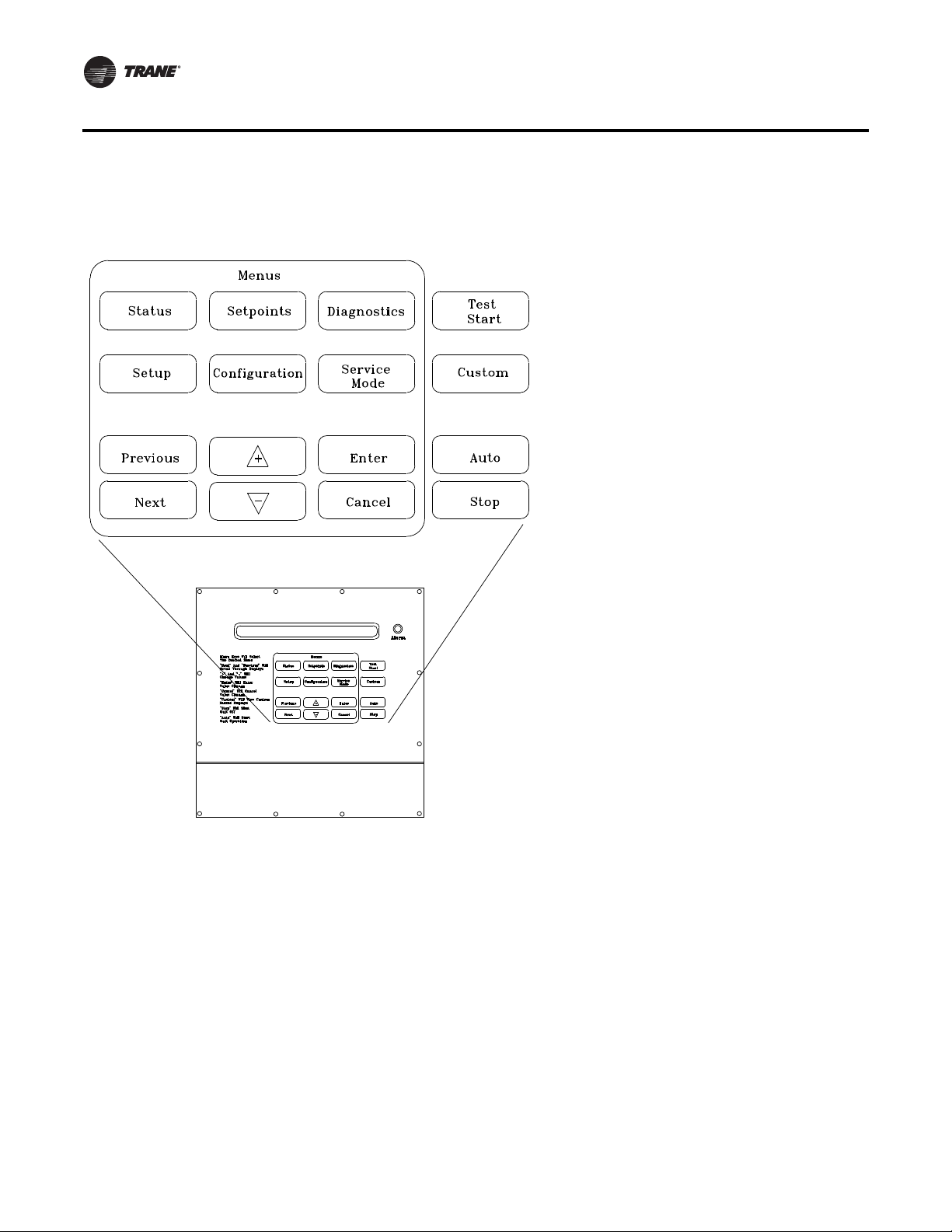
(standard on all units) The LHI and RHI (Local and Remote Human Interface) share a similar keypad which is illustrated,
see Figure 1. Human Interface Module" on page 11. This device enables the customer, building owner, or contractor, to
communicate to the Rooftop unit the necessary parameters for unit operation such as cooling and heating Setpoints,
demand limiting, ventilation override modes, etc
The local (unit mounted) Human Interface and the Remote Human Interface Panel functions are identical, except for
Service mode which is not available on the Remote Human Interface Panel.
The local HI Module is located in the unit’s main control panel. A small door located in the unit’s control panel door allows
access to the HI Module’s keypad and display window.
There is a 2 line by 40 character LCD screen which provides status information for the various unit functions as well as
menus used to set or modify the operating parameters.There is a 16 key keypad adjacent to the LCD screen, which allows
the operator to scroll through the various menus and make adjustments to the setpoints, etc.
The LCD screen has a backlight that makes the information easier to read.The light will go out if no keys are pressed for
30 minutes. If it goes out, simply press the Status key.
The information displayed in the LCD window will be top-level status information unless the operator initiates other
displays.
At power-up, the Human Interface LCD will display one of four initial screens illustrated in the “General Status” section.
10 RT-SVP07D-EN
Page 11
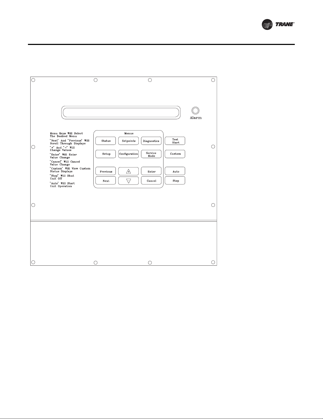
Figure 1. Human Interface Module
Commonly Used Acronyms
Menu Keys
The six main menu keys illustrated in Figure 2. Human Interface Keypad,(Status, Setpoints, Setup, Configuration,
Diagnostics, and Service Mode) are used to bring up the various interactive menus where the user inputs and accesses
unit operating data. Pressing these keys will display the initial screen for the menu designated by the key’s name. The
following information describes the keys and their functions when viewing the various menus.
Note:
1. If no key is pressed for 30 minutes while the LCD is displaying a menu screen, it will revert back to the unit operating
status screen.
Status Key
Pressing the Status key causes the LCD to display the operating status screen; i.e. “On”, “Unit Stop”, “External Stop”,
“Emergency Stop”,“Service Mode”. Pressing the Next key allows the operator to scroll through the screens which provide
information such as air and refrigerant temperatures, humidity levels, fan operation, compressor operation, heater
operation, economizer positioning, exhaust operation, as well as heating, cooling, and compressor lockout setpoints.
Pressing the Status key while viewing any of the data screens will cause the LCD to go back to the operating status screen.
RT-SVP07D-EN 11
Page 12

Commonly Used Acronyms
Setpoints Key
Pressing the Setpoints key will cause the LCD screen to display the first of the setpoint screens where the operator will
designate default temperature and pressure setpoints. While scrolling through the setpoint screens, pressing this key
again will cause the LCD to display the first setpoint screen.
Diagnostics Key
Pressing the Diagnostics key at any time will allow the operator to view any active unit diagnostics, or 20 of the most
recently logged unit diagnostics. The LCD screen will display one of the diagnostic screens (depending on which
diagnostic, if any, is present). If no key is pressed for 30 minutes while the screen is displaying diagnostic information,
it will revert back to the operating status display.
Configuration Key
Pressing the Configuration key will cause the LCD screen to display the first of the configuration screens where the
operator will designate unit configuration data such as unit type, capacity, system control, etc.
This information was programmed at the factory. Pressing the configuration key at any level in the configuration menu
will display the first configuration screen.
Note:
1. This key should be used if the unit’s configuration data is lost or new options are added in the field, and to view current
configuration.
2. The Stop key must be pressed prior to making any changes under the Configuration menu.
Setup Key
Pressing the Setup key will cause the LCD screen to display screens where the operator will designate various operating
parameters such as temperature and pressure ranges, limits, percentages, setpoint source selections, and sensor input
definitions for the control of the rooftop unit’s various operating modes. Pressing the Setup key at any level in the setup
menu will display the first setup screen.
Service Mode Key
Pressing the Service Mode key causes the LCD to display the first of the service test mode screens showing various unit
components which may be turned on or off for the particular test being performed. Once the status of these components
is designated, the LCD will display screens that allow the operator to designate the TEST START time delay for each test.
Data Manipulation Keys
The six data manipulation keys illustrated in Figure 2. Human Interface Keypad" on page 14, (Enter, Cancel, + (Plus), -
(Minus), Previous, and Next are used to modify the data within the screens (change values, move the cursor, confirm
choices)
Enter Key
The Enter key will confirm the new values that were designated by pressing the + (Plus)or- (Minus) keys at all edit points.
When viewing status and diagnostics screens, it has no function.
Cancel Key
After changing data, at an editable screen, but before confirming it with the Enter key, pressing the Cancel key will return
the data to its previous value.This key shall also function to clear active diagnostics.
+ (Plus) Key
When viewing a setpoint screen, this key will increase the value of the displayed item per the units selected.When working
with a status menu, it will add the current status display to the CUSTOM MENU. When viewing setup, or service test
screens, it will proceed forward though all the selections of that menu item, increase setpoints, toggle choices OFF to ON,
DISABLED to ENABLED.
12 RT-SVP07D-EN
Page 13

Unit Operation Keys
- (Minus) Key
When viewing a setpoint screen, this key will decrease the value of the displayed item per the units selected. When
working with a CUSTOM MENU, it will delete the current selected display. When viewing setup, or service test screens,
it will proceed backwards though all the selections of that menu item, decrease setpoints, toggle choices ON to OFF,
ENABLED to DISABLED.
Next Key
Pressing the Next key causes the LCD to scroll forward through the various displays for each menu. At displays with
multiple edit points it moves the cursor forward from one edit point to another.
Previous Key
Pressing the Previous key causes the LCD to scroll backward through the various displays for each menu. At displays with
multiple edit points, it moves the cursor backward from one edit point to another.
Unit Operation Keys
The four unit operation keys (Auto, Stop,Test Start, Custom) are used to control and monitor the unit in normal
operating mode, and also to initiate an active unit service test event.
Auto Key
Pressing the Auto key at any time will cause the display to go to the top level status display and, if the unit is shutdown,
will cause the unit to begin operation in the appropriate mode no matter what level in the menu structure is currently being
displayed. If the current display is an editable display, the Auto key will confirm the desired edit point similar to the Enter
key.
Stop Key
Pressing the Stop key will cause the unit to transition to the stop state. If the current display is editable, pressing the Stop
key will cancel the desired edit similar to the Cancel key. Prior to making any changes to the configuration menu screens,
the Stop key must be pressed.
Test Start Key (Service Test Mode Start)
Pressing theTest Start key while viewing any screen in the Service Mode Menu will start the service test. Pressing this
key while displaying any screen other than the Service Mode Menu will not start the service test, and has no other function.
Custom Key
Pressing the Custom key will change the display to the Custom Menu.This menu is simply a status menu that contains
screens that the user monitors most frequently.The custom menu can only contain five status screens.To create the
custom menu, press the Status key, followed by the Next key (this brings up the initial status screen). If you want to add
this screen to the custom menu, press the + (Plus) key, if not, press the Next key again until a status screen appears that
you would like to add to the custom menu. Pressing the + (Plus) key while viewing any of the various status screens will
add that screen to the custom menu. Once the custom menu is programmed it can be accessed by pressing the Custom
key.To remove a status screen from the custom menu, press the Custom key, then press the Next key until the status
screen that you want to remove appears, then press the - (Minus) key.
General Status Display
Anytime the rooftop unit is powered up, or the Status,Auto,orStop keys are pressed, the unit mounted Human Interface
will display one of the following general status display screens.The operator will then be able to enter keystrokes which
will allow him to navigate through a set of menus and submenus in order to provide/access various monitoring, setup,
RT-SVP07D-EN 13
Page 14
General Status Display
and configuration information. The Human Interface will not display screens or parts of screens for which the unit is not
configured.
Figure 2. Human Interface Keypad
14 RT-SVP07D-EN
Page 15
General Status Display
Unit “Off” or “Stopped”
If at power up the unit is not running, the following display will appear on the Human Interface LCD screen. When this
screen is being displayed, the only functional keys are the six menu keys (Status, Setpoints, Diagnostics, Setup,
Configuration, and Service Mode), the Auto key, the Custom key, and the Stop key.
Stop by Network Supply Fan ON
Initializing Diagnostics
Top Right Field:
Unit Off
Unit Stopped
External Stop
Emergency Stop
Stop by Network
Unit Starting
Service Mode Off
Bottom Left Field:
(blank)
Shutdown
Initializing
Freeze Avoidance
Active
Supply Fan OFF
Supply Fan ON
Bottom Right Field:
(blank)
(Diagnostics)
Used With: Top Status Display
(Shown when unit is off or stopped)
Possible Values:
[see field descriptions at left]Top Left Field:
Unit “On”
If the unit has entered an operating state (running), the following display will appear on the Human Interface LCD screen.
When this screen is being displayed, the only functional keys are the six menu keys (Status, Setpoints, Diagnostics,
Setup, Configuration, and Service Mode), the Auto key, the Custom key, and the Stop key.
VVDA OA Flow 380.0 CCFM Supply Fan ON
Occupied Cool 2 Diagnostics
Top Right Field:
Supply Fan ON
Supply Fan OFF
CVZT
VVDA
CVDA
VVZT
Top Middle Field:
(blank)
OA Flow 0 to 500
CCFM
Freeze Avoidance
Used With: Top Status Display
(Shown when unit is on)
Possible Values:
[see field descriptions at left]Top Left Field:
Bottom Left Field:
(blank)
Occupied
Unoccupied
MorningWU
DaytimeWU
Standby
Shutdown
Occupied TOV
Initializing
Tempering
Rapid Restart
RT-SVP07D-EN 15
Bottom Middle Field:
(blank)
Heat 1 to 6
Cool 1 to 4
OA Dmpr 0 to 100 %
Dehumid
Purge
Humidify
SA Fan 0 to 100%
Bottom Right Field:
(blank)
Diagnostics
Page 16
General Status Display
“Emergency Override” Active
If the unit has entered an Emergency Override mode of operation, one of the following displays will appear on the Human
Interface LCD screen.
Ventilation Override Mode
PRESSURIZE Diagnostics
Used With: LCI or BCI Options
Top Left Field:
Top Right Field: (blank)
Bottom Left Field:
PRESSUREIZE
DEPRESSURIZE
PURGE
SHUTDOWN
FIRE
Bottom Right Field:
Diagnostics (Trouble Indicator)
(blank)
“VOM” Active
If at power up the unit is running and has entered a Ventilation Override mode of operation, the following display will
appear on the Human Interface LCD screen.
Ventilation Override Mode A
Diagnostics
Used With: VOM Option
Possible Values:
Top Right Field: A, B, C, D, E, OFF
Bottom Left Field:
(blank)
Bottom Right Field:
Diagnostics (Trouble Indicator)
(blank)
“No Configuration” Condition
If at power up the unit has not been programmed with the necessary configuration data for normal unit operation, the
following display will appear on the Human Interface LCD screen.When this screen is being displayed, the only functional
keyistheConfiguration key.
Note: This screen will only appear when the RTM has been field replaced. Refer to the Configuration Menu section.
NO CONFIGURATION PRESENT
Used With: All Units
PRESS CONFIGURATION KEY
16 RT-SVP07D-EN
Page 17

General Status Display
Factory Presets
The UCM controlled unit has many operating functions which are preset at the factory, but may be modified to meet the
unique requirements of each job. The following list in Table 2, identifies each of the unit’s adjustable functions and the
value assigned to it. If these factory presets match the application’srequirements, simply press the Auto key at the Human
Interface module to begin unit operation (after completing the Pre-Start and Start-Up procedures in the Installation,
Operation, and Maintenance manual). If the application requires different settings, turn to the listed page beside the
function, press the designated function menu key, then press and hold the Next or Previous key until its screen appears
on the LCD. Once the proper screen appears, simply follow the programming instructions given below the applicable
screen in this manual.
Note: Listed items availability is dependent on unit configuration.)
Table 2. Factory Presets List (Note: Listed Items availability is dependent on unit configuration.
To adjust
Adjustable Function Factory Preset Changed To
General Function
Unit Address (Comm3/Comm4only) 1
System Mode Auto ___________ Setup
Supply Fan Mode Auto ___________ Setup
Unit Start Delay 0 ___________ Setup
Single Zone VAV Econ Control Enabled ___________ Setup
Single Zone VAV Heat Control Disabled ___________ Setup
Daytime Warm-up Disabled ___________ Setup
Morning Warm-up Enabled ___________ Setup
Morning Warm-up type Cycling ___________ Setup
Supply Air Tempering Disabled ___________ Setup
Unoccupied Mechanical Cooling Enable ___________ Setup
Unoccupied Heating Enable ___________ Setup
Unoccupied Mechanical Cooling Enable ___________ Setup
Unoccupied Heating Enable ___________ Setup
Occupied Dehumidification Enable ___________ Setup
Unoccupied Dehumidification Enable ___________ Setup
Occupied Humidification Disable ___________ Setup
Unoccupied Humidification Disable ___________ Setup
Rapid Restart Economizer Control Disable ___________ Setup
VCM Preheat Output Disable ___________ Setup
Demand Limit Definition - Cooling None ___________ Setup
Demand Limit Definition - Heating None ___________ Setup
Compressor Lead/Lag Enable ___________ Setup
Evap Temperature Limit 35 F ___________ Setup
Coil Frost Cutout Temp 30 F ___________ Setup
Isolation Damper Interlock Disable ___________ Setup
___________ Setup
press...
Information Format
Display Text English ___________ Setup
Display Units English ___________ Setup
VAV Control
SA Temp Reset Cool None ___________ Setup
RT-SVP07D-EN 17
Page 18

General Status Display
Table 2. Factory Presets List (continued)(Note: Listed Items availability is dependent on unit configuration.
To adjust
Adjustable Function Factory Preset Changed To
Reset Cool Start Temp (Zone/OA) (72/90) ___________ Setup
Reset Cool End Temp (Zone/OA) (69/70) ___________ Setup
Reset Cool Max Amount 5 ___________ Setup
SA Temp Reset Heat None ___________ Setup
Reset Heat Start Temp (Zone/OA) (65/10) ___________ Setup
Reset Heat End Temp (Zone/OA) (68/60) ___________ Setup
Reset Heat Max Amount 10 ___________ Setup
VAV Box Stroke Time 6 Min ___________ Setup
Max Occ. IGV/VFD Command 100 % ___________ Setup
Economizer Control
Economizer Control Enable Type Drybulb ___________ Setup
Unoccupied Economizer Enable ___________ Setup
Head Pressure Control
Sump Drain Relay Control (on power loss) Drain ___________ Setup
Sump Purge Interval Time Disabled ___________ Setup
(a)
(a)
(a)
(120/60 sec.) ___________ Setup
(80/70 deg F) ___________ Setup
(90/80 deg F) ___________ Setup
Disabled ___________ Setup
Sump Purge Duration Time (IPak-I/IPak-II)
Sump Water Heater Setpoint 38 F ___________ Setup
Low Limit (Air-cooled/Water-cooled)
Upper Limit 120 deg F ___________ Setup
Temporary low limit suppression 20 deg F ___________ Setup
Efficiency check point 105 deg F ___________ Setup
Low amb. control point (Air-cooled/Water-cooled)
Alternate Refrigerant Type
(a)
press...
Sensor Source Selection
Daytime Warm-Up RTM Zone Temp ___________ Setup
Occupied Zone Control RTM Zone Temp ___________ Setup
Unoccupied Zone Control RTM Zone Temp ___________ Setup
Morning Warm-Up RTM Zone Temp ___________ Setup
Space Humidity Control RTM Space Humidity ___________ Setup
Dehumid OVRD Zone Temp RTM Zone Temp ___________ Setup
Zone Reset Function RTM Zone Temp ___________ Setup
Rapid Restart Function ECEM Return Temp ___________ Setup
Monitor RTM Zone Temp ___________ Setup
Outside Air Ventilation
Demand Control Ventilation Disable ___________ Setup
Active/Passive DCV Control Passive ___________ Setup
OA Flow Compensation Enabled ___________ Setup
OA Flow C02 Reset (IPak-INon-DCV) Disabled ___________ Setup
CO2 Start (IPak-I Non-DCV) 800 ___________ Setup
CO2 Max (IPak-I Non-DCV) 1000 ___________ Setup
18 RT-SVP07D-EN
Page 19

General Status Display
Table 2. Factory Presets List (continued)(Note: Listed Items availability is dependent on unit configuration.
To adjust
Adjustable Function Factory Preset Changed To
OA Flow Calibration Gain (Left) 1.0 ___________ Setup
OA Flow Calibration Offset (Left) 0 CFM ___________ Setup
OA Flow Calibration Gain (Right) 1.0 ___________ Setup
OA Flow Calibration Offset (Right) 0 CFM ___________ Setup
OA Normalization 100 CCFM ___________ Setup
OA Flow Calibration Data - Altitude: 0 Ft ___________ Setup
RTM Alarm Output Definition Any Active Diagnostic ___________ Setup
GBAS Input/Output Definitions
GBAS (0-5) Analog Input 1 Definitions Not Assigned ___________ Setup
GBAS (0-5) Analog Input 2 Definitions Not Assigned ___________ Setup
GBAS (0-5) Analog Input 3 Definitions Not Assigned ___________ Setup
GBAS (0-5) Analog Input 4 Definitions Not Assigned ___________ Setup
GBAS (0-5) Output 1 Definitions Not Assigned ___________ Setup
GBAS (0-5) Output 2 Definitions Not Assigned ___________ Setup
GBAS (0-5) Output 3 Definitions Not Assigned ___________ Setup
GBAS (0-5) Output 4 Definitions Not Assigned ___________ Setup
GBAS (0-5) Output 5 Definitions Not Assigned ___________ Setup
press...
GBAS (0-10) Analog Input 1 Definitions Not Assigned ___________ Setup
GBAS (0-10) Analog Input 2 Definitions Not Assigned ___________ Setup
GBAS (0-10) Analog Input 3 Definitions Not Assigned ___________ Setup
GBAS (0-10) Analog Input 4 Definitions Not Assigned ___________ Setup
GBAS (0-10) Output 1 Definitions Not Assigned ___________ Setup
GBAS (0-10) Output 2 Definitions Not Assigned ___________ Setup
GBAS (0-10) Output 3 Definitions Not Assigned ___________ Setup
GBAS (0-10) Output 4 Definitions Not Assigned ___________ Setup
GBAS (0-10) Output 5 Definitions Not Assigned ___________ Setup
Ventilation Override Definition See Definitions ___________ Setup
Temperature Input Offset for...
RTM Zone Temperature
RTM Aux Temperature
Outdoor Air Temperature
Heat Aux Temperature
Return Air Temperature
0 deg F ___________ Setup
0 deg F ___________ Setup
0 deg F ___________ Setup
0 deg F ___________ Setup
0 deg F ___________ Setup
Device Characteristics…
Outside Air Damper (if equipped)
Actuator Setup
Max Stroke Time
Max Voltage
Direct ___________ Setup
30 sec ___________ Setup
10 VDC ___________ Setup
RT-SVP07D-EN 19
Page 20

General Status Display
Table 2. Factory Presets List (continued)(Note: Listed Items availability is dependent on unit configuration.
To adjust
Adjustable Function Factory Preset Changed To
Min Voltage
Supply Fan IGV/VFD (if equipped)
Actuator Setup
Max Stroke Time
Max Voltage
Min Voltage
Return Fan VFD (if equipped)
Actuator Setup
Max Stroke Time
Max Voltage
Min Voltage
Exhaust Damper/VFD (if equipped)
Actuator Setup
Max Stroke Time
Max Voltage
Min Voltage
2 VDC ___________ Setup
Direct ___________ Setup
30/0 sec ___________ Setup
10 VDC ___________ Setup
2 VDC ___________ Setup
Direct ___________ Setup
60/0 sec ___________ Setup
10 VDC ___________ Setup
2 VDC ___________ Setup
Direct ___________ Setup
60 sec ___________ Setup
10 VDC ___________ Setup
0 VDC ___________ Setup
press...
Hydronic Heat (if equipped)
Actuator Setup
Max Stroke Time
Max Voltage
Min Voltage
Low Ambient Damper Ckt-1 (if equipped)
Actuator Setup
Max Stroke Time
Max Voltage
Min Voltage
Low Ambient Damper Ckt-2 (if equipped)
Actuator Setup
Max Stroke Time
Max Voltage
Min Voltage
Cond Fan VFD Ckt -1(if equipped)
Actuator Setup
Max Stroke Time
Max Voltage
Min Voltage
Direct ___________ Setup
60 sec ___________ Setup
10 VDC ___________ Setup
2 VDC ___________ Setup
Direct ___________ Setup
60 sec ___________ Setup
10 VDC ___________ Setup
2 VDC ___________ Setup
Direct ___________ Setup
60 sec ___________ Setup
10 VDC ___________ Setup
2 VDC ___________ Setup
Direct ___________ Setup
60 sec ___________ Setup
10 VDC ___________ Setup
0 VDC ___________ Setup
20 RT-SVP07D-EN
Page 21

General Status Display
Table 2. Factory Presets List (continued)(Note: Listed Items availability is dependent on unit configuration.
To adjust
Adjustable Function Factory Preset Changed To
Cond Fan VFD Ckt-2 (if equipped)
Actuator Setup
Max Stroke Time
Max Voltage
Min Voltage
Direct ___________ Setup
60 sec ___________ Setup
10 VDC ___________ Setup
0 VDC ___________ Setup
press...
Modulating Gas Heat Actuator (if equipped)
Actuator Setup (Ipak-I/Ipak-II)
(a)
Max Stroke Time
Max Voltage
Min Voltage (Ipak-I/Ipac-II)
(a)
Outdoor Air Bypass Damper (if equipped)
Actuator Setup
Max Stroke Time
Max Voltage
Min Voltage
Exhaust Bypass Damper (if equipped)
Actuator Setup
Max Stroke Time
Max Voltage
Min Voltage
Variable Speed Comp (if equipped)
Actuator Setup
Max Stroke Time
Max Voltage
Min Voltage
(Direct/Reverse) ___________ Setup
90 sec ___________ Setup
10 VDC ___________ Setup
(5 VDC/2 VDC) ___________ Setup
Direct ___________ Setup
60 sec ___________ Setup
10 VDC ___________ Setup
2 VDC ___________ Setup
Direct ___________ Setup
60 sec ___________ Setup
10 VDC ___________ Setup
2 VDC ___________ Setup
Direct ___________ Setup
30 sec ___________ Setup
10 VDC ___________ Setup
0 VDC ___________ Setup
Control Algorithm Tuning Parameters
(Partial)
(a)
VAV Cooling Control Gains
Proportional (w-VSC / wo-VSC)
Reset Time (w-VSC/wo-VSC)
(2.0%/F/3.3%/F) ___________ Setup
(100 Sec/50 Sec) ___________ Setup
Zone Control Occupied Heating Proportional Gain
IPak I Gas
IPak I Electric
IPak II Gas
IPak II Electric-90 kw
IPak II Electric -140 kw
IPak II Electric-265 kw
IPak II Electric-300 kw
30.0 deg F ___________ Setup
45.0 deg F ___________ Setup
30.0 deg F ___________ Setup
45.0 deg F ___________ Setup
60.0 deg F ___________ Setup
75.0 deg F ___________ Setup
75.0 deg F ___________ Setup
RT-SVP07D-EN 21
Page 22

General Status Display
Table 2. Factory Presets List (continued)(Note: Listed Items availability is dependent on unit configuration.
To adjust
Adjustable Function Factory Preset Changed To
CV Air Economizer Control Gains
Proportional
Reset Time
Rate Time
Bias
SZVAV Cooling Control Gains
Proportional
Reset Time
Rate Time
Bias
Zone Control Modulating Heat Gains
Proportional
Reset Time
Rate Time
Bias
SZVAV Heating Control Gains
Proportional
Reset Time
Rate Time
Bias
Rapid DX Interstage Timing
10.0 % F ___________ Setup
DISABLE ___________ Setup
0 Sec ___________ Setup
0 deg F ___________ Setup
6.0 % F ___________ Setup
1200 Sec ___________ Setup
0 Sec ___________ Setup
0 deg F ___________ Setup
10.0 % F ___________ Setup
DISABLE ___________ Setup
0 Sec ___________ Setup
0 deg F ___________ Setup
8.0% F ___________ Setup
1200 Sec ___________ Setup
0 Sec ___________ Setup
0 deg F ___________ Setup
30 Sec ___________ Setup
press...
Default Setpoints
Supply Air Cooling
Supply Air Heating
SA Cool Deadband 8.0 F ___________ Setpoints
SA Heat Deadband 4.0 F ___________ Setpoints
DWU Initiate 67 F ___________ Setpoints
DWU Terminate 71 F ___________ Setpoints
Occupied Zone Cooling 74 F ___________ Setpoints
Occupied Zone Heating 71 F ___________ Setpoints
Zone Derived Setpoint 4 F ___________ Setpoints
Unoccupied Zone Cooling 85 F ___________ Setpoints
Unoccupied Zone Heating 60 F ___________ Setpoints
Unoccupied Zone MWU 72 F ___________ Setpoints
Rapid Restart Critical Temp
Occ Dehumidification 60% ___________ Setpoints
Occ Dehumid Hysteresis Offset 5% ___________ Setpoints
Unocc Dehumidification 60% ___________ Setpoints
Unocc Dehumid Hysteresis Offset 5% ___________ Setpoints
Supply Air Reheat Setpoint 70 F ___________ Setpoints
Supply Air Reheat Deadband 4 F ___________ Setpoints
Maximum Reheat Valve Limit 85% ___________ Setpoints
Dehumid Ovrd High Zone Temp 75 F ___________ Setpoints
(VAV/SZVAV)
(VAV/SZVAV)
(a)
(a)
(a)
(55 F/50 F) ___________ Setpoints
(100 F/105 F) ___________ Setpoints
90 F ___________ Setpoints
22 RT-SVP07D-EN
Page 23

General Status Display
Table 2. Factory Presets List (continued)(Note: Listed Items availability is dependent on unit configuration.
To adjust
Adjustable Function Factory Preset Changed To
Dehumid Ovrd Low Zone Temp 68 F ___________ Setpoints
Cond Coil Purge Interval 90 Min ___________ Setpoints
Occ Humidification 30% ___________ Setpoints
Occ Humidification Hysteresis Offset 5% ___________ Setpoints
Unocc Humidification 30% ___________ Setpoints
Unocc Humidification Hysteresis Offset 5% ___________ Setpoints
Economizer Cooling Setpoint Suppression (CV) 3 F ___________ Setpoints
Reference Enthalpy 25 BTU/LB ___________ Setpoints
Economizer Drybulb Enable Stpt 75 F ___________ Setpoints
Supply Air Low Limit 50 F ___________ Setpoints
VCM Preheat Actuate Temp 35 F ___________ Setpoints
Design Min CO
DCV Min CO
Design Min OA Flow (DCV) 220 CCFM ___________ Setpoints
DCV Min OA Flow 67 CCFM ___________ Setpoints
DCV Min OA Flow Deadband 5 CCFM ___________ Setpoints
Min OA Flow w\ VCM Set per unit size ___________ Setpoints
Min OA Flow Deadband Set per unit size ___________ Setpoints
Design Min OA Damper Position (DCV) 15% ___________ Setpoints
DCV Min OA Damper Position 5% ___________ Setpoints
OA Damper Min Position (non-DCV) 15% ___________ Setpoints
OAD Min Position w/IGV/VFD at 0% 25% ___________ Setpoints
OAD Min Position w/IGV/VFD at 50% 20% ___________ Setpoints
OAD Min Position w/IGV/VFD at 100% 15% ___________ Setpoints
OAD Min Position (Default) 15% ___________ Setpoints
Supply Air Pressure 2.0 IWC ___________ Setpoints
Supply Air Pressure High Limit 4.0 IWC ___________ Setpoints
Supply Air Pressure Deadband 0.5 IWC ___________ Setpoints
Max Return Plenum Pressure 0.8 IWC ___________ Setpoints
Return Plenum Pressure Deadband 0.1 IWC ___________ Setpoints
Space Pressure - Setpoint 0.08 IWC ___________ Setpoints
Space Pressure - Deadband .04 IWC ___________ Setpoints
Space Pressure Low Limit -0.2 IWC ___________ Setpoints
Exhaust Enable Point 25% ___________ Setpoints
Exhaust Inhibit Point DISABLE ___________ Setpoints
Low Ambient Comp. Lockout (Standard Units) 50 F ___________ Setpoints
Low Ambient Comp. Lockout (Low Ambient Units) 0 F ___________ Setpoints
Standby Freeze Avoidance 0% ___________ Setpoints
Recovery Frost Avoidance Setpoint 27 F ___________ Setpoints
(DCV) 1000 PPM ___________ Setpoints
2
2
800 PPM ___________ Setpoints
press...
Setpoint Source Selection For...
Supply Air Temp Cooling Hi Default ___________ Setpoints
Supply Air Temp Heating Hi Default ___________ Setpoints
Occupied Zone Cooling Hi Default ___________ Setpoints
RT-SVP07D-EN 23
Page 24
General Status Display
Table 2. Factory Presets List (continued)(Note: Listed Items availability is dependent on unit configuration.
To adjust
Adjustable Function Factory Preset Changed To
Occupied Zone Heating Hi Default ___________ Setpoints
Unoccupied Zone Cooling Hi Default ___________ Setpoints
Unoccupied Zone Heating Hi Default ___________ Setpoints
Morning Warm-Up Hi Default ___________ Setpoints
Economizer Dry Bulb Enable Hi Default ___________ Setpoints
Outside Damper Minimum Position Hi Default ___________ Setpoints
Occupied Dehumidification Hi Default ___________ Setpoints
Unoccupied Dehumidification Hi Default ___________ Setpoints
Supply Air Reheat Hi Default ___________ Setpoints
Occupied Humidity Hi Default ___________ Setpoints
Unoccupied Humidity Hi Default ___________ Setpoints
Minimum Outside Air Flow Rate Hi Default ___________ Setpoints
Supply Air Pressure Hi Default ___________ Setpoints
Space Pressure Hi Default ___________ Setpoints
(a) Field replacement of control modules requires proper human interface setup to insure unit performance
press...
Password Protected Screens
Some of the operating displays on the Human Interface LCD screens and require a password to change.The following
screens display the various programming sections that require a password in order to view or to modify the preset
operating parameters. The password for each screen is a different series of + (Plus)or- (Minus) key strokes in a
predefined sequence. Shown below are the password protected screens, and the passwords for accessing them.
The following screens display the various programming sections that require a specific password to be entered by a
qualified operator in order to modify the operating parameters. The following screen will appear if the password is not
entered within approximately 15 seconds.
Password Entry Time Limit Exceeded
Configuration is Password Protected
Please Enter Password: __________
1. Press the + or - keys in this sequence ( + - - - ) to access
this restricted screen.
2. Press the Enter key to confirm the password and enter the
menu.
Ventilation Override Mode _______
Enter Password to Lock Definition:
24 RT-SVP07D-EN
Page 25
1. Press the + or - keys in this sequence ( + - - + ) to lock each
VOM Mode.
2. Press the Enter key to confirm the password and Lock the
definitions.
Diagnostic Reset is Password Protected
Please Enter Password: ____________
1. Press the + or - keys in this sequence ( - + + ) to access this
restricted screen.
2. Press the Enter key to confirm the diagnostic reset.
Diagnostic Log is Password Protected
Please Enter Password: __________
General Status Display
1. Press the + or - keys in this sequence ( - + + -) to access this
restricted screen.
2. Press the Enter key to confirm clearing the diagnostic log.
Turning Parameters are Password Protected
Please Enter Password: __________
1. Contact Clarksville Service for Password.
Navigating the Human Interface Screens
In the following sections the user will be presented with a number of screens and submenus that follow the selection of
a main menu key entry (Status, Setpoints, Diagnostics, Setup, Configuration, Service Mode and Custom). When
a submenu is presented, it may be accessed by pressing the Enter key or, skipped entirely by pressing the Next key. Upon
entering a menu, or submenu, the user will navigate through the desired selections by pressing the Next and Previous
keys.The most probable keystroke would be to press Next to cycle forward through the screens as shown in these
sections, but pressing the Previous key may be desirable to review previous screens or to quickly navigate to the end
of a menu.
Once the user has navigated to a desired selection, the + (Plus) and - (Minus) keys will be pressed to cycle through the
selection range of the menu item.The range of each item selected is dependent upon the item and is listed for each screen
in the following sections. For instance, if the user has selected a Configuration item typical choices displayed with each
+ (Plus)or- (Minus) keystroke may be Installed or Not Installed.IfaSetup menu were accessed a choice may be Enabled
or Disabled.Temperature Setpoints will typically cycle through their range one degree at a time, and so on. Similar to
pressing the Previous key above, pressing the - (Minus) key to decrement through the range may provide quick access
to the desired value.
Once a change has been made to the desired menu item the user will press the Enter key to accept the change, or press
the Cancel key to ignore the modification and return the displayed item to its original value.
RT-SVP07D-EN 25
Page 26
STATUS Menu
The status menu is used to view various operating conditions such as temperatures, pressures and humidity levels. It is
also used to view unit component status such as fan, compressor, heater, and economizer operation, as well as setpoint
status.
The screens shown in this section are for example only. Pressing the + (Plus) key while viewing any of the status display
screens will add that screen to the Custom menu. While viewing the Custom menu, a screen can be removed by pressing
the – (Minus) key.
When a status screen is displayed for 30 minutes without a key being pressed, the LCD screen will revert to the general
operating status display. If this happens, press the Status key again to return to the status menu.The following are
examples of status screens that may be viewed by pressing the Status key.
Note:
1. Many of the screens displayed in this section are applicable only for the options that are installed in the unit
and may not be visible on your unit.
2. The range for some selections depend upon a sensor connected to a control module. Normal ranges
expected will be listed for each screen shown. If the sensor is operating outside its normal limits, or has
failed, “+ERR” will appear if out of range high, and “-ERR” if it is out of range low.
Press the Status key to begin viewing the status screens.
TOP LEVEL STATUS SCREEN
VVDA OA Flow 350.0 CCFM Supply Fan ON
Occupied Cool 4 Diagnostics
• Press Next/Previous keys to navigate.
GENERAL SYSTEM STATUS SUBMENU SCREENS
General System Status Submenu
Press ENTER to View Data in this Submenu
• Press Next key to skip this Submenu.
Active Unit Control Source: LOCAL
Active Cluster Member Role: STANDALONE
RTM Supply Fan Relay: OFF
RTM Supply Airflow Proving: FLOW
Note: One of the three following screens will be shown based on
supply air pressure options.
Used With: All Units
Used With: BAS Interface Installed
Possible Values:
Source: LOCAL, BAS/NETWORK
Role: STANDALONE, SLAVE, MASTER• Press Next/Previous keys to navigate.
Used With: All Units
Possible Values:
Fan Relay: ON, OFF
Airflow Proving: FLOW, NO FLOW• Press Next/Previous keys to navigate.
26 RT-SVP07D-EN
Page 27
STATUS Menu
Supply Fan IGV/VFD Target: 30%
Master’s Algorithm Command to All Units
OR
Supply Fan IGV/VFD Cmd Opening To 30 %
Active Supply Air Pressure 2.0 IWC
“Limited To” when shown indicates an active override.
OR
Active Supply Air Pressure 2.0 IWC
• Press Next/Previous keys to navigate.
Note: One of the three following screens will be shown based on
power exhaust options.
Exhaust Fan OFF
Used With: Clustered VVDA Units
Possible Values: 0 to 100%
Used With: VVDA Units
Possible Values:
Cmd: 0 to 100%
Press: 0.0 to 7.9 IWC“Opening To” and ”Closing To” indicate direction.
Used With: CVDA/CVZT Units
Possible Values: 0.0 to 7.9 IWC
Used With: Units w Power Exhaust w/o
Statitrac, w/o Return Fan
Possible Values: ON, OFF
OR
Exhaust Damper/VFD Target: 70 %
Master’s Algorithm Command to All Units
OR
Exhaust Fan ON Space Pressure 0.00 IWC
Exhaust Damper/VFD Opening To 32 %
“Opening To” and ”Closing To” indicates direction.
“Limited To” when shown indicates an active override.
• Press Next/Previous keys to navigate.
Note: One of the four following screens will be shown based on
heating type options.
Used With: Clustered, w/Statitrac, w/o
Return Fan Units
Possible Values: 0 to 100%
Used With: Units w/Statitrac, w/o
Return Fan
Possible Values:
Fan: ON, OFF
Pressure:
IPakI: -0.2 to 0.3 IWC
IPakII: -0.67 to 0.67 IWC
Damper/VFD: 0 to 100%
RT-SVP07D-EN 27
Page 28
STATUS Menu
Electric Heat: ENABLED
Stage: 6 K11: ON K12: ON K1: ON
“ENABLED” indicates heat is available.
“DISABLED” indicates heating is not allowed.
“LIMITED” indicates heating is available at reduced capacity.
OR
Gas Heat: ENABLED
Stage: 2 K11: ON K12: ON K1: ON
“ENABLED” indicates heat is available.
“DISABLED” indicates heating is not allowed.
“LIMITED” indicates heating is available at reduced capacity.
OR
Hydronic Heat: ENABLED
Valve Position: Opening To: 100 %
“ENABLED” indicates heat is available.
“DISABLED” indicates heating is not allowed.
“LIMITED” indicates heating is available at reduced capacity.
“Opening To” and ”Closing To” indicates direction.
Used With: Units w/Electric Heat
Possible Values:
Electric Heat:
ENABLED,
DISABLED By Setup,
LIMITED By Demand Limit
DISALBED By BAS/Network
Stage: 0,1,2,3,4,5,6
K*: ON, OFF
Used With: Units w/Staged Gas Heat
Possible Values:
Gas Heat:
ENABLED,
DISABLED By Setup,
LIMITED By Demand Limit
DISALBED By BAS/Network
Stage: 0,1,2
K*: ON, OFF
Used With: Units w/Hydronic Heat
Possible Values:
Hydronic Heat:
ENABLED,
DISABLED By Setup,
LIMITED By Demand Limit
DISABLED By Low Air Temp
DISALBED By BAS/Network
Position: 0 to 100%
OR
Mod Gas Heat: ENABLED
Valve Position: Opening To: 100 %
“ENABLED” indicates heat is available.
“DISABLED” indicates heating is not allowed.
“LIMITED” indicates heating is available at reduced capacity.
“Opening To” and ”Closing To” indicates direction.
• Press Next/Previous keys to navigate.
28 RT-SVP07D-EN
Used With: Units w/Mod Gas Heat
Possible Values:
Mod Gas Heat:
ENABLED,
DISABLED By Setup,
LIMITED By Demand Limit
DISABLED By Low Air Temp
DISALBED By BAS/Network
Position: 0 to 100%
Page 29
STATUS Menu
Chilled Water: ENABLED
Valve Position: Opening To 100 %
“ENABLED” indicates cooling is available.
“DISABLED” indicates cooling is not allowed.
“LIMITED” indicates cooling is available at reduced capacity.
“Opening To” and ”Closing To” indicates direction.
• Press Next/Previous keys to navigate.
Dehumidification Status: DISABLED
by Comfort Control Override is Active
Table 3. Dehumidification Lockout Sources
Value Displayed in Bottom Field Disable Conditions
Used With: Air Handler Units w/Chilled
Water
Possible Values:
Chilled Water:
ENABLED,
DISABLED By Setup,
LIMITED By Demand Limit
DISABLED By Low Air Temp
DISALBED By BAS/Network
Position: 0 to 100%
Used With: Units w/Dehumidification
Top Line Possible Values: ENABLED,
DISABLED
Bottom line Possible Values:
When ENABLED is Shown:
(blank line)
When LOCKED is Shown:
[See “Table 3. Dehumidification
Lockout Sources” Below]
Disabled By Call for Cooling Demand Limit ........................ Compressors unavailable due to demand limit.
Disabled By Compressor Lockout Sources .......................... Required compressors are not available.
Disabled By Occ Dehumid Function Disable ....................... Occupied Dehumid. control is disabled.
Disabled By Dehumid Override Zone Temp High/Low .......... VVDA/CVDA critical zone temp is too high/low.
Disabled By OA Temperature Out Of Range ....................... Outdoor air temperature is out of range.
Disabled By Unocc Dehumid Function Disable..................... Unoccupied Dehumid. control is disabled.
Disabled By Comfort Control Override is Active................... Comfort cooling control has priority.
Disabled By Required Sensor Failure Condition ................... Sensor(s) for dehumid. control have failed.
Disabled By Sat Reheat Cond Temp Sensor Fail .................. Sensor for dehumid. control have failed.
Disabled By Reheat Head Pressure High Limit..................... Reheat circuit is experiencing high pressures.
Disabled By Condenser Coil Purge is Active ........................ Active purge mode temporary override.
Disabled By Comp Press Differential.................................. Excessive refrig. pressures across compressors.
• Press Next/Previous keys to navigate.
Humidification Status: ENABLED
Humidification is Active
• Press Next/Previous keys to navigate.
Used With: Units w/Humidification
Top Right Field: ENABLED, DISABLED
Bottom Field:
The following shown when DISABLED:
by Occ Humidification Function Disable
by Unocc Humid Function Disable
The following shown when ENABLED:
Humidification is Inactive
Humidification is Active
RT-SVP07D-EN 29
Page 30
STATUS Menu
End of Submenu (NEXT) to Enter STATUS
• Press Next/Previous keys to navigate.
COMPRESSOR STATUS SUBMENU SCREENS
Compressor Status Submenu
Press ENTER to View Data in This Submenu
• Press the Next key to skip this Submenu.
Note: Combinations of the following screens will be shown based on
unit cooling capacity option.
Compressor Relay K10 Locked
Disabled By Compressor Protection (MORE)
Note: There will be 2 screens shown for this configuration, one
screen for K10 and one for K11.
• Press Next/Previous keys to navigate.
OR
Compressor Relay K11 Locked
Disabled By Compressor Protection (MORE)
Note: There will be 4 screens shown for this configuration, one for
K11, one for K12*, one for K3, and one for K4*. See the following
replacement screen for K12 when a variable speed compressor is
installed on 40-70 ton units. K12 and K4 will show either Enabled
or Activated by Compressor Protection when the compressor is ON.
Important:
• *See the following replacement screen for K12 when a variable
speed compressor is installed on 40-70 ton units.
• *K12 and K4 will show either Enabled, or Activated by Compressor
Protection, when the compressor is ON.
Used With: Units w/DX Cooling
Used With: IPakI 20-30Ton DX Cooling
Possible Values:
Compressor Relay:
K10: 1
K11: 2
Top Right Field:
ON, OFF, LOCKED
Bottom Field:
When ON or OFF is Shown: ENABLED
When LOCKED is Shown:
[See “Table 4. Compressor Lockout
Sources" on page 32”]
Used With: IPakI 40-130Ton DX Cooling
Possible Values:
Compressor Relay:
K11: 1
K12: 2
K3: 3
K4: 4
Top Right Field:
ON, OFF, LOCKED
Bottom Field:
When ON or OFF is Shown: ENABLED
When LOCKED is Shown:
[See “Table 4. Compressor Lockout
Sources" on page 32”]
st
Compressor
nd
Compressor
st
Compressor
nd
Compressor
rd
Compressor
th
Compressor
• Press Next/Previous keys to navigate.
30 RT-SVP07D-EN
Page 31

STATUS Menu
Capacity of Variable Speed Comp: 0%
Disabled By Compressor Protection (MORE)
Notes:
• This screen replaces K12 if a variable speed compressor is installed.
• *Applied Design Capacity is the maximum cooling capacity of the
variable speed compressor for this unit’s tonnage design.
• Press Next/Previous keys to navigate.
OR
Ckt 1 Compr Relay K11: OFF
Enabled
Notes:
• There will be 2 screens shown for the configuration, one for K11and
one for K12.
• *K12 will show either Enabled or Activated by Compressor
Protection when the compressor is ON.
• Press Next/Previous keys to navigate.
Used With: IPakI 40-70 Ton DX Cooling
Configured w/Variable Speed
Compressor
Possible Values: % of Applied Design
Capacity*
Top Right Field: 0–100%
Bottom Field:
During Normal control: [blank]
When VSC is locked: [See “Table 4.
Compressor Lockout Sources" on page
32”]
Used With: IPakII DX Cooling
Possible Values:
Compressor Relay:
K11: 1
K12: 2
Top Right Field:
ON, OFF, LOCKED
Bottom Field:
When ON or OFF is Shown: ENABLED
When LOCKED is Shown:
[See “Table 4. Compressor Lockout
Sources” Below]
st
Compressor
nd
Compressor
Ckt 2 Compr Relay K3: ON
Enabled
• There will be 2 screens shown for the configuration, one for K3 and
one for K4.
• K4 will show either Enabled or Activated by Compressor Protection
when the compressor is ON.
Used With: IPakII DX Cooling
Possible Values: Possible Values:
Compressor Relay:
Top Right Field:
Bottom Field:
When ON or OFF is Shown: ENABLED
When LOCKED is Shown:
rd
K3: 3
K4: 4
ON, OFF, LOCKED
[See “Table 4. Compressor Lockout
Sources” Below]
Compressor
th
Compressor
RT-SVP07D-EN 31
Page 32

STATUS Menu
Table 4. Compressor Lockout Sources
Value Displayed in Bottom Field
Disabled By Compressor Protection................... Compressor proving input did not close.
Disabled By Contactor/Drive Failure.................. Compressor proving input stuck closed.
Disabled By Low Pressure Cutout ..................... Low pressure cutout input to MCM.
Disabled By Bad Cond Temp Sensor .................. Temp sensor is out of range.
Disabled By Demand Limit............................... From GBAS or BAS/Network.
Disabled By Frost Protection ............................ Leaving evap temp. < coil frost setpoint.
Disabled By BAS/Network Lockout .................... BAS demand or capacity limited.
Disabled By Minimum Off Time......................... 3 minutes.
Disabled By Low Ambient Lockout .................... Ambient temp. < Low Ambient Lockout Stpt.
Disabled By Ventilation Override....................... Source is VOM input A-E, or BAS/Network.
Disabled By LPC Delay .................................... 3 minutes.
Disabled By Water Flow Status......................... Evap. condenser water flow failure.
Disabled By Cond Coil Purge Request ................ Dehumidification coil purge mode.
Disabled By Sump Temp Sensor Fail.................. Evap. condenser sump water temperature.
Disabled By Low Refrig Charge......................... Evap. temp. difference exceeded for 10 min.
Disabled By Ckt ............................................. Evap Low Limit Entering evaporator temp. is excessively low.
Disabled by Reheat Ckt Evap Low Limit ............. Entering evaporator temp. is excessively low.
Disabled By Evap Temp Sensor Fail ................... Entering or leaving temp. sensor(s) failed.
Disabled by Comp Press Differential.................. Excessive refrig. pressures across compressors.
Disabled By Sump Min Level Sensor Fail ............ Evap. condenser min level switch failed.
Disabled By Sump Pump Failure ....................... Evap. condenser pump proving failed.
Disabled By Sump Min Level Control ................. Evap. condenser water level marginal.
Activated By Compressor Protection.................. Comps on for refrigerant management
Lockout Conditions
• Press Next/Previous keys to navigate.
Circuit 1 Evap Diff: 5.0°F
Enter Evap: 48.5°F Leave Evap: 53.5°F
"Evap Diff:" and associated value not displayed if:
1. circuit is inactive, or
2. for first ten minutes of circuit operation, or
3. HGBP is installed
"Enter Evap:" and associated value not displayed if:
1. HGBP is installed
• Press Next/Previous keys to navigate.
Circuit 1
Saturated Condensing Temp: 100.0°F
• Press Next/Previous keys to navigate.
Used With: DX Cooling
Possible Values:
Evap Diff: 0.0 to 200.0ºF
Enter Evap: -40.0 to 200.0ºF
Leave Evap: -40 to 200.0ºF
Used With: DX Cooling.
Possible Values:
Temp: -40.0 to 200.0ºF
32 RT-SVP07D-EN
Page 33

STATUS Menu
Circuit 2 Evap Diff: 12.0°F
Enter Evap: 40.0°F Leave Evap: 52.0°F
"Evap Diff:" and associated value not displayed if:
1. circuit is inactive, or
2. for first ten minutes of circuit operation, or
3. HGBP is installed
"Enter Evap:" and associated value not displayed if:
1. HGBP is installed
• Press Next/Previous keys to navigate.
Circuit 2
Saturated Condensing Temp: 97.0°F
• Press the Next key to navigate forward.
Circuit 1 Cond Fan Staging
K1: ON K2: ON Stage 4
“K2:” status not displayed, and maximum stage is 1, on watercooled condenser units.
• Press Next/Previous keys to navigate.
Used With: DX Cooling > 40Ton
Possible Values:
Evap Diff: 0.0 to 200.0ºF
Enter Evap: -40.0 to 200.0ºF
Leave Evap: -40 to 200.0ºF
Used With: DX Cooling > 40Ton
Possible Values:
Temp: -40.0 to 200.0ºF
Used With: DX Cooling
Possible Values:
K1: ON, OFF; K2: ON, OFF
Bottom Right Field:
OFF
Stage 1
Stage 2
Stage 3
Stage 4
Circuit 2 Cond Fan Staging
K5: ON K6: ON Stage 4
“K6:” status not displayed and maximum stage is 1 on watercooled condenser units.
• Press Next/Previous keys to navigate.
Condenser Fan Speed:
Circuit 1: 100% Circuit 2: 100%
“Circuit 2:” only shown for units
• Press Next/Previous keys to navigate.
RT-SVP07D-EN 33
> 40Tons.
Used With: DX Cooling > 40Ton
Possible Values:
K5: ON, OFF; K6: ON, OFF
Bottom Right Field:
OFF
Stage 1
Stage 2
Stage 3
Stage 4
Used With: DX Cooling w/Low Ambient
Option or Water-Cooled Condensers
Possible Values:
Circuit 1: 0 to 100%
Circuit 2: 0 to 100%
Page 34

STATUS Menu
Condenser Sump Water Temp: 73.1°F
Condenser Sump Heater Relay: OFF
“Cond Sump Heater Relay” only shown if Sump Heater installed.
• Press Next/Previous keys to navigate.
Condenser Sump Pump Relay Command: ON
Condenser Sump Pump Proving: FLOW
• Press Next/Previous keys to navigate.
Condenser Sump Fill Relay: OFF
Condenser Sump Fill Valve: OPEN
• Press Next/Previous keys to navigate.
Condenser Sump Drain Relay: ON
Condenser Sump Drain Valve: CLOSED
“Relay” and “Valve” states are configurable based on the need to
hold water in the sump or drain it on power loss. See the IOM, and
“ Table 7: Sump Drain Valve States" on page 110 in Service Test
section for further information.
Used With: DX Cooling w/Water-Cooled
Condensers
Possible Values:
Temp: 0.0 to 200.0ºF
Relay: ON, OFF
Used With: DX Cooling w/Water-Cooled
Condensers
Possible Values:
Relay: ON, OFF
Proving: FLOW, NO FLOW
Used With: DX Cooling w/Water-Cooled
Condensers
Possible Values:
Relay: ON, OFF
Valve: CLOSED, OPEN
Used With: DX Cooling w/Water-Cooled
Condensers
Possible Values:
Sump Drain Relay: ON, OFF
Sump Drain Valve: CLOSED, OPEN
• Press Next/Previous keys to navigate.
Cond Sump Water Level Max Input: OPEN
Cond Sump Water Level Min Input: CLOSED
• Press Next/Previous keys to navigate.
External Sump Drain Request: INACTIVE
• Press Next/Previous keys to navigate.
Reheat Coil Pumpout Relay: OFF
Reheat Coil Pumpout Valve: CLOSED
• Press Next/Previous keys to navigate.
34 RT-SVP07D-EN
Used With: DX Cooling w/Water-Cooled
Condensers
Possible Values:
Max Input: CLOSED, OPEN
Min Input: CLOSED, OPEN
Used With: DX Cooling w/Water-Cooled
Condensers
Possible Values: ACTIVE, INACTIVE
Used With: DX Cooling w/
Dehumidification
Possible Values:
Relay: ON, OFF
Valve: CLOSED, OPEN
Page 35

STATUS Menu
Dehumid Reheat Valve Position: 0%
Dehumid Cooling Valve Position: 100%
• Press Next/Previous keys to navigate.
Active Outside Air Temperature 70.0°F
Low Ambient Comp Lockout Temp: 50°F
• Press Next/Previous keys to navigate.
End of Submenu (NEXT) to Enter STATUS
• Press Next/Previous keys to navigate.
ECONOMIZER STATUS SUBMENU SCREENS
Used With: DX Cooling w/
Dehumidification
Possible Values:
Reheat Valve: 0 to Max Reheat Valve
Position Setpoint (see Setpoints
Menu)
Cooling Valve: 10 to 100%
Used With: DX Cooling
Possible Values:
Active Outside Air Temp: -40 to
200.0ºF Lockout Temp: -20 to 80ºF
Default(s):
Standard: 50ºF
Low-Amb. w/Hot Gas Bypass: 0ºF
Low-Amb. w/o Hot Gas Bypass: 10ºF
Economizer Status Submenu
Press ENTER to View Data in This Submenu
• Press the Next key to skip this Submenu.
Air Economizing: ENABLED
Outside Air Damper Pos: Closing to 10%
Air Economizing: LIMITED By SA Low Limit
Outside Air Damper Pos: 30%
“Opening to” and “Closing to” indicates direction.
“LIMITED By SA Low Limit” indicates economizer sub-cooling
prevention is activated and the OA Damper is limited.
• Press Next/Previous keys to navigate.
Used With: Units w/Economizer
Used With: Units w/Economizer
Possible Values:
Economizing: ENABLED/DISABLED
Damper Pos: 0 to 100%or
RT-SVP07D-EN 35
Page 36

STATUS Menu
Active Outside Air Enthalpy 29.5 BTU/LB
ECEM Return Air Enthalpy 34.0 BTU/LB
Energy Recovery is installed.
• Press Next/Previous keys to navigate.
Active Outside Air Temperature 86.0°F
ECEM Return Air Temperature 78.0°F
Energy Recovery is installed.
• Press Next/Previous keys to navigate.
Active Outside Air Humidity 30 %RH
ECEM Return Air Humidity 62 %RH
Energy Recovery is installed.
• Press Next/Previous keys to navigate.
Used With: Units w/Economizer
Possible Values:
OA Enthalpy: 10 to 35 BTU/LB
RA Enthalpy: 10 to 35 BTU/LB"Return Air Enthalpy" is displayed if Comparative Enthalpy or
Used With: Units w/Economizer
Possible Values:
OA Temp: -40 to 200°F
RA Temp: -40 to 200°F"Return Air Temperature” is displayed if Comparative Enthalpy or
Used With: Units w/Economizer
Possible Values:
OA Humidity: 10 to 90%
RA Humidity: 10 to 90%“Return Air Humidity” is displayed if Comparative Enthalpy or
End of Submenu (NEXT) to Enter STATUS
• Press Next/Previous keys to navigate.
OUTSIDE AIR VENTILATION STATUS SUBMENU SCREENS
Outside Air Ventilation Status Submenu
Press ENTER to View Data in this Submenu
• Press the Next key to skip this Submenu.
Demand Control Ventilation is ENABLED
Space CO2 Level: 600 PPM
is ENABLED
• Press Next/Previous keys to navigate.
Note: One of the three following screens will be shown based on
fresh air measurement and DCV options.
Used With: Units w/Fresh Air Options
Used With: All Units
Possible Values:
DCV: ENABLED, DISABLED
CO
Level: 50 to 2200 PPM"Space CO2 Level” is shown only if “Demand Control Ventilation”
2
36 RT-SVP07D-EN
Page 37

STATUS Menu
DCV Min OA Flow Target: 250.0 CCFM
Deadband: 5.0 CCFM OA Flow 234.3 CCFM
OR
Active Min OA Flow Setpoint: 140.3 CCFM
Deadband: 6.8 CCFM OA Flow 143.5 CCFM
OR
Active Min OA Flow Setpoint: 140.3 CCFM
CO2 Level 1100 PPM OA Damper Pos: 99 %
• Press Next/Previous keys to navigate.
Used With: Fresh Air Measurement
(VCM) w/DCV and Demand Control
Ventilation ENABLED
Possible Values:
Target: 0 to 650 CCFM
Deadband: 5.0 to 200 CCFM
OA Flow: 0 to 650 CCFM
Used With: Fresh Air Measurement
(VCM) w/DCV and Demand Control
Ventilation DISABLED
Possible Values:
Setpoint: 0 to 650 CCFM
Deadband: 5.0 to 200 CCFM
OA Flow: 0 to 650 CCFM
Used With: Fresh Air Measurement
(VCM) w/o DCV and CO2 Reset ENABLED
Possible Values:
Setpoint: 0 to 650 CCFM
CO2 Level: 50 to 2000 PPM
OA Damper Pos: 0 to 650 CCFM
Outside Air Flow Total: 335.4 CCFM
Left: 167.2 CCFM Right: 168.2 CCFM
• Press Next/Previous keys to navigate.
Outside Air Damper Target: 27 %
Outside Air Damper Position: 24 %
• Press Next/Previous keys to navigate.
VCM Preheater Output Control: OFF
VCM Module Aux Temp Input: 47.2 °F
• Press Next/Previous keys to navigate.
End of Submenu (NEXT) to Enter STATUS
• Press Next/Previous keys to navigate.
Used With: Fresh Air Measurement
(VCM) w/DCV
Possible Values: 0 to 650 CCFM
Used With: Units w/Fresh Air Options
Possible Values: 0 to 100%
Used With: Fresh Air Measurement
(VCM) w/DCV or OA Damper Min Position
(VCM) w/DCV and Preheat ENABLED
Possible Values:
Output Control: ON, OFF
Aux Temp Input: -40.0 to 200.0ºF
RT-SVP07D-EN 37
Page 38

STATUS Menu
RETURN FAN STATUS SUBMENU SCREENS
Return Fan Status Submenu
Press ENTER to View Data in This Submenu
• Press the Next key to skip this Submenu.
Return Fan Relay: ON
Return Airflow Proving: ON
• Press Next/Previous keys to navigate.
Return Fan VFD Command: 45 %
Return Plenum Pressure: 0.8 IWC
• Press Next/Previous keys to navigate.
Return Plenum Pressure Target: 0.8 IWC
Return Fan VFD Pos: Opening to 45 %
“Limited to” indicates an active override.
Used With: Units w/Return Fan Option
Used With: Units w/Return Fan Option
Possible Values: ON, OFF
Used With: Units w/Return Fan Option
Possible Values:
Command: 0 to 100%
Pressure: -0.7 to 3.5 IWCTop line shown only if Return Fan VFD is installed.
Used With: Units w/Return Fan Option
Possible Values:
Target: -0.5 IWC, or 0.1 to 2.5 IWC
VFD Pos: 0 to 100%“Opening to” and ”Closing to” indicates direction.
• Press Next/Previous keys to navigate.
Max Return Plenum Pressure Stp: 1.2 IWC
High Limit: 3.5 IWC Deadband: 0.2 IWC
• Press Next/Previous keys to navigate.
End of Submenu (NEXT) to Enter STATUS
• Press Next/Previous keys to navigate.
SINGLE ZONE VAV STATUS SUBMENU SCREENS
Single Zone VAV Control Status Submenu
Press ENTER to View Data in this Section
• Press Next/Previous keys to navigate.
Used With: Units w/Return Fan Option
Possible Values:
Pressure Stp: 0.1 to 2.5 IWC
Deadband: 0.1 to 1.0 IWC
High Limit: 3.5 IWC (non-adjustable)
Used With: Units w/SZVAV(VVZT)
Option
38 RT-SVP07D-EN
Page 39

STATUS Menu
Active SA Target High Limit: 123.0 °F
Active SA Max Target Setpoint: 100.0 °F
The Target High Limit is a calculated value which corresponds to
the Maximum Fan Speed during heating (see SA Target Setpoint
on following screen). The Max Target Setpoint reflects the SA
Heating Setpoint value and corresponds to the Minimum Fan
Speed during heating.
• Press Next/Previous keys to navigate.
Active SA Target Setpoint: 74.0 °F
Active SA Temperature: 73.9 °F
The SA Target Setpoint is a calculated discharge setpoint based on
zone temperature conditions. Heating and Cooling is staged to
maintain SA Temperature to this setpoint. The range is clamped
on the high end to Max Target Setpoint (see previous screen) and
to the low end to Min Target Setpoint (see next screen).
• Press Next/Previous keys to navigate.
Active SA Min Target Setpoint: 50.0 °F
Active SA Target Low Limit: 38.4 °F
The Target Low Limit is a calculated value which corresponds to the
Maximum Fan Speed during cooling (see SA Target Setpoint on
previous screen). The Min Target Setpoint reflects the SA Cooling
Setpoint value and corresponds to the Minimum Fan Speed during
cooling.
• Press Next/Previous keys to navigate.
Used With: Units w/SZVAV(VVZT)
Option
Possible Values:
High Limit: (calculated)
Max Target: Equal to SA Cooling
Setpoint
Fan speed modulation in heating occurs
when the Target Setpoint modulates
between the Max Setpoint and High Limit
Setpoint.
Used With: Units w/SZVAV(VVZT)
Option
Possible Values:
SA Target: Max Target – Min Target
SA Temp: See SA Temp status.
Used With: Units w/SZVAV(VVZT)
Option
Possible Values:
MinTarget: Equal to SA Heating
Setpoint
Low Limit: (calculated)
Fan speed modulation in cooling occurs
when the Target Setpoint modulates
between the Min Setpoint and Low Limit
Setpoint.
End of Submenu (NEXT) to Enter STATUS
• Press Next/Previous keys to navigate.
ENERGY RECOVERY STATUS SUBMENU SCREENS
Energy Recovery Status Submenu
Press ENTER to View Data in This Submenu
• Press the Next key to skip this Submenu.
RT-SVP07D-EN 39
Used With: Units w/Energy Recovery
Option
Page 40

STATUS Menu
Energy Wheel Relay: ON
Energy Wheel Proving: ON
• Press Next/Previous keys to navigate.
Outside Air Bypass Damper Pos: 0%
Exhaust Air Bypass Damper Pos: 15%
• Press Next/Previous keys to navigate.
Energy Wheel Frost Avoidance: INACTIVE
Leaving Recovery Exhaust Temp: 45.0°F
• Press Next/Previous keys to navigate.
MPM Preheat Relay: OFF
• Press Next/Previous keys to navigate.
End of Submenu (NEXT) to Enter STATUS
Used With: Units w/Energy Recovery
Option
Possible Values: ON, OFF
Used With: Units w/Energy Recovery
Option
Possible Values: 0 to 100%
Used With: Units w/Energy Recovery
Option
Possible Values:
Frost Avoidance: ACTIVE, INACTIVE;
Exhaust Temp: -40.0 to 200.0ºF
Used With: Units w/Energy Recovery
Option w/Preheat
Possible Values: ON, OFF
• Press Next/Previous keys to navigate.
CONTROLLING SETPOINT STATUS SUBMENU SCREENS
Controlling SETPOINT Status Submenu
Press ENTER to View Data in This Submenu
• Press the Next key to skip this Submenu.
Active Supply Air Cooling STP From
HI (KEYPAD) SETPOINT MENU Is 55°F
Used With: All Units
Used With: VVDA or CVDA Units
Possible Values:
HI (KEYPAD) SETPOINT MENU
ZONE SENSOR SETPOINT INPUT
NSB PANEL SETPOINT INPUT
GBAS 0-5 VDC MODULE
GBAS 0-10 VDC MODULE
BAS/NETWORK
Range: 40 to 90ºF• Press Next/Previous keys to navigate.
40 RT-SVP07D-EN
Page 41

STATUS Menu
Active Supply Air Heating STP From
HI (KEYPAD) SETPOINT MENU Is 100°F
• Press Next/Previous keys to navigate.
Active Daytime Warmup Setpoints
Initiate: 67 °F Terminate: 71 °F
Active Occupied Zone Cooling STP From
HI (KEYPAD) SETPOINT MENU is 71°F
Used With: VVDA or CVDA Units w/
Hydronic Heat, Modulating Gas Heat, or
IpakII w/Electric Heat
Possible Values:
HI (KEYPAD) SETPOINT MENU
ZONE SENSOR SETPOINT INPUT
GBAS 0-5 VDC MODULE
GBAS 0-10 VDC MODULE
BAS/NETWORK
Range: 40 to 180ºF
Used With: Units w/DWU ENABLED
Possible Values:
Initiate: 50 to 87ºF
Terminate: 53 to 90ºF• Press Next/Previous keys to navigate.
Used With: CVZT Units w/DX Cooling
Possible Values:
HI (KEYPAD) SETPOINT MENU
ZONE SENSOR SETPOINT INPUT
NSB PANEL SETPOINT INPUT
GBAS 0-5 VDC MODULE
GBAS 0-10 VDC MODULE
BAS/NETWORK
Range: 52 to 90ºF• Press Next/Previous keys to navigate.
Active Occupied Zone Heating STP From
HI (KEYPAD) SETPOINT MENU is 71°F
• Press Next/Previous keys to navigate.
Active Unoccupied Zone Cooling STP From
HI (KEYPAD) SETPOINT MENU is 85°F
RT-SVP07D-EN 41
Used With: CVZT w/Heat, VV/CVDA w/
DWU or MWU Installed
Possible Values:
HI (KEYPAD) SETPOINT MENU
ZONE SENSOR SETPOINT INPUT
NSB PANEL SETPOINT INPUT
GBAS 0-5 VDC MODULE
GBAS 0-10 VDC MODULE
BAS/NETWORK
Range: 50 to 88ºF
Used With: All Units
Possible Values:
HI (KEYPAD) SETPOINT MENU
ZONE SENSOR SETPOINT INPUT
NSB PANEL SETPOINT INPUT
GBAS 0-5 VDC MODULE
GBAS 0-10 VDC MODULE
BAS/NETWORK
Range: 52 to 90ºF• Press Next/Previous keys to navigate.
Page 42
STATUS Menu
Active Unoccupied Zone Heating STP From
HI (KEYPAD) SETPOINT MENU is 60°F
Active Morning Warmup Setpoint From
HI (KEYPAD) SETPOINT MENU is 72°F
Active Rapid Restart Critical Stpt From
HI (KEYPAD) SETPOINT MENU is 90°F
• Press Next/Previous keys to navigate.
Used With: Units w/Heat Installed
Possible Values:
HI (KEYPAD) SETPOINT MENU
ZONE SENSOR SETPOINT INPUT
NSB PANEL SETPOINT INPUT
GBAS 0-5 VDC MODULE
GBAS 0-10 VDC MODULE
BAS/NETWORK
Range: 50 to 88ºF• Press Next/Previous keys to navigate.
Used With: Units w/MWU ENABLED
Possible Values:
HI (KEYPAD) SETPOINT MENU
ZONE SENSOR SETPOINT INPUT
NSB PANEL SETPOINT INPUT
GBAS 0-5 VDC MODULE
GBAS 0-10 VDC MODULE
BAS/NETWORK
Range: 52 to 90ºF• Press Next/Previous keys to navigate.
Used With: Units w/Rapid Restart
Possible Values:
HI (KEYPAD) SETPOINT MENU
Range: 75 to 95ºF
Active Occ Dehumidification Setpt From
HI (KEYPAD) SETPOINT MENU is 60%
Active Unocc Dehumidification Setpt From
HI (KEYPAD) SETPOINT MENU is 60%
42 RT-SVP07D-EN
Used With: Units w/Dehumid. Option
Possible Values:
HI (KEYPAD) SETPOINT MENU
GBAS 0-5 VDC MODULE
GBAS 0-10 VDC MODULE
BAS/NETWORK
Range: 40 to 65%• Press Next/Previous keys to navigate.
Used With: Units w/Dehumid. Option
Possible Values:
HI (KEYPAD) SETPOINT MENU
GBAS 0-5 VDC MODULE
GBAS 0-10 VDC MODULE
BAS/NETWORK
Range: 40 to 65%• Press Next/Previous keys to navigate.
Page 43

STATUS Menu
Active Supply Air Reheat Setpoint From
HI (KEYPAD) SETPOINT MENU is 70.0°F
Active Occ Humidification Setpt From
HI (KEYPAD) SETPOINT MENU is 40%
Active Unocc Humidification Setpt From
HI (KEYPAD) SETPOINT MENU is 20%
Used With: Units w/Dehumid. Option
Possible Values:
HI (KEYPAD) SETPOINT MENU
GBAS 0-5 VDC MODULE
GBAS 0-10 VDC MODULE
BAS/NETWORK
Range: 60 to 80F• Press Next/Previous keys to navigate.
Used With: Units w/Humid. Option
Possible Values:
HI (KEYPAD) SETPOINT MENU
GBAS 0-5 VDC MODULE
GBAS 0-10 VDC MODULE
BAS/NETWORK
Range: 20 to 50%• Press Next/Previous keys to navigate.
Used With: Units w/Humid. Option
Possible Values:
HI (KEYPAD) SETPOINT MENU
GBAS 0-5 VDC MODULE
GBAS 0-10 VDC MODULE
BAS/NETWORK
Range: 20 to 50%• Press Next/Previous keys to navigate.
Active Econ DB Enable Setpoint From
HI (KEYPAD) SETPOINT MENU is 75°F
Active OA Damper Min Position STP From
HI (KEYPAD) SETPOINT MENU is 25%
• Press Next/Previous keys to navigate.
Used With: Units w/Economizer
Possible Values:
HI (KEYPAD) SETPOINT MENU
GBAS 0-5 VDC MODULE
GBAS 0-10 VDC MODULE
BAS/NETWORK
Range: 40 to 90ºF• Press Next/Previous keys to navigate.
Used With: Units w/0-25% Motorized
Damper, or Economizer and OA CFM
Compensation Function DISABLED or OA
Damper Min Position Setpoint Source
Selection is Not “HI (KEYPAD)
SETPOINT”
Possible Values:
HI (KEYPAD) SETPOINT MENU
GBAS 0-5 VDC MODULE
GBAS 0-10 VDC MODULE
BAS/NETWORK
Range: 0 to 100%
RT-SVP07D-EN 43
Page 44

STATUS Menu
Active Min OA Flow Setpoint From
HI (KEYPAD) SETPOINT MENU is 34.2 CCFM
• Press Next/Previous keys to navigate.
Active Design Min OA Flow Setpoint From HI
(KEYPAD) SETPOINT MENU is 34.2 CCFM
• Press Next/Previous keys to navigate.
Used With: Units w/Fresh Air
Measurement (VCM) w/o DCV Option
Possible Values:
HI (KEYPAD) SETPOINT MENU
GBAS 0-5 VDC MODULE
GBAS 0-10 VDC MODULE
BAS/NETWORK SETPOINT
Range: 0 to Max Unit Airflow
[See “Table 7. Max Unit Airflows" on page
91” in the Setpoints Section Below]
Used With: Units w/Fresh Air
Measurement (VCM) w/DCV Option
Possible Values:
HI (KEYPAD) SETPOINT MENU
GBAS 0-5 VDC MODULE
GBAS 0-10 VDC MODULE
BAS/NETWORK SETPOINT
Range: 0 to Max Unit Airflow
[See “Table 7. Max Unit Airflows" on page
91” in the Setpoints Section]
Active Min OA Flow Target From
VCM Module is 120.5 CCFM
• Press Next/Previous keys to navigate.
Active Supply Air Pressure STP From
HI (KEYPAD) SETPOINT MENU is 2.0 IWC
Active Supply Air Pressure Setpoints
High Limit: 4.0 IWC Deadband: 0.5 IWC
• Press Next/Previous keys to navigate.
Used With: Units w/Fresh Air
Measurement (VCM) w/DCV Option
Possible Values:
VCM Module
BAS/NETWORK
Range: 0 to Max Unit Airflow
[See “Table 7. Max Unit Airflows" on page
91” in the Setpoints Section]
Used With: VVDA Units
Possible Values:
HI (KEYPAD) SETPOINT MENU
GBAS 0-5 VDC MODULE
GBAS 0-10 VDC MODULE
BAS/NETWORK SETPOINT
Range: 0.7 to 5.1 IWC• Press Next/Previous keys to navigate.
Used With: VVDA or Units w/Supply Air
Pressure Sensor Present
Possible Values:
High Limit: 1.2 to 4.7 IWC
Deadband: 0.1 to 2.0 IWC
44 RT-SVP07D-EN
Page 45

STATUS Menu
Active Space Pressure Setpoint From
HI (KEYPAD) SETPOINT MENU is 0.08 IWC
Active Space Pressure Deadband 0.1 IWC
• Press Next/Previous keys to navigate.
End of Submenu (NEXT) to Enter STATUS
• Press Next/Previous keys to navigate.
CONTROLLING SENSOR STATUS SUBMENU SCREENS
Used With: Units w/Statitrac
Possible Values:
HI (KEYPAD) SETPOINT MENU
GBAS 0-5 VDC MODULE
GBAS 0-10 VDC MODULE
BAS/NETWORK SETPOINT
Range: -0.2 to 0.30 IWC• Press Next/Previous keys to navigate.
Used With: Units w/Statitrac
Possible Values: 0.02 to 0.20 IWC
Controlling Sensor Status Submenu
Used With: All Units
Press ENTER to View Data in This Submenu
• Press the Next key to skip this Submenu.
Active Supply Air Temp Sensv Input From
BAS/NETWORK is 50.0°F
Active Daytime WU Temp Sensor Input From
RTM ZONE TEMP INPUT is 82.0°F
• Press Next/Previous keys to navigate.
Used With: All Units
Possible Values:
RTM Supply Air Temp Input
BAS/Network• Press Next/Previous keys to navigate.
Used With: Units w/DWU ENABLED
Possible Values:
RTM ZONE TEMP INPUT
NSB PANEL TEMP SENSOR INPUT
RTM AUX TEMP INPUT
HEAT MODULE AUX TEMP INPUT
ECEM RETURN AIR TEMP INPUT BAS/
NETWORK SENSOR
Range: -40 to 200ºF
RT-SVP07D-EN 45
Page 46
STATUS Menu
Active Occ Zone Temp Sensor Input From
RTM ZONE TEMP INPUT is 75.0°F
• Press Next/Previous keys to navigate.
Active Unocc Zone Temp Sensor Input From
RTM ZONE TEMP INPUT is 75.0°F
• Press Next/Previous keys to navigate.
Active Morning WU Temp Sensor Input From
RTM ZONE TEMP INPUT is 82.0°F
• Press Next/Previous keys to navigate.
Active Space Humidity Sensor Input From
RTM SPACE HUMIDITY INPUT is 55%
• Press Next/Previous keys to navigate.
Used With: CV or SZVAV Units
Possible Values:
[See “Possible Values:” Above]
Used With: All Units
Possible Values:
[See “Possible Values:” Above]
Used With: Units w/MWU ENABLED
Possible Values:
[See “Possible Values:” Above]
Used With: Units w/Dehumid. or Humid.
Option
Possible Values:
RTM SPACE HUMIDITY INPUT
ECEM RA HUMIDITY INPUT
BAS/NETWORK
Range: 10 to 90%
Active Rapid Restart Sensor Input From
ECEM RETURN AIR TEMP INPUT is 82.0°F
• Press Next/Previous keys to navigate.
Active Space CO2 Sensor Input From
VCM SPACE CO2 INPUT is 600 PPM
• Press Next/Previous keys to navigate.
Active Dehumid OVRD Temp Input From
RTM ZONE TEMP INPUT is 73.5°F
Used With: Units w/Rapid Restart.
Possible Values:
[See “Possible Values:” Above]
Used With: Units w/Fresh Air
Measurement (VCM) w/DCV, or CO
Reset ENABLED
Possible Values:
VCM SPACE CO
BAS/NETWORK
Range: 50 to 2000 PPM
Used With: Units w/Dehumid. Option
Possible Values:
RTM ZONE TEMP INPUT
NSB PANEL TEMP SENSOR INPUT
RTM AUX TEMP INPUT
HEAT MODULE AUX TEMP INPUT
ECEM RETURN AIR TEMP INPUT
BAS/NETWORK SENSOR
Range: -40 to 200ºF• Press Next/Previous keys to navigate.
INPUT
2
2
46 RT-SVP07D-EN
Page 47
STATUS Menu
Active Zone Reset Temp Sensor Input From
RTM ZONE TEMP INPUT is 82.0°F
• Press Next/Previous keys to navigate.
Active OA Temperature Sensor Input From
RTM OUTSIDE AIR TEMP INPUT is 86.0°F
• Press Next/Previous keys to navigate.
Active Outside Air Humidity Input From
OA HUMIDITY SENSOR INPUT is 30 %
Active Supply Air Press Input From
RTM SA PRESSURE INPUT is 2.1 IWC
• Press Next/Previous keys to navigate.
Used With: All Units with Reset Select
not selected as None.
Possible Values:
[See “Possible Values:” Above]
Used With: All Units
Possible Values:
RTM OUTSIDE AIR TEMP INPUT BAS/
NETWORK
Range: -40 to 200ºF
Used With: Units w/Economizer Option
Possible Values:
OA HUMIDITY SENSOR INPUT
BAS/NETWORK SENSOR
Range: 10 to 90%• Press Next/Previous keys to navigate.
Used With: VVDA or Units w/Supply Air
Pressure Sensor Present
Possible Values:
RTM SA PRESSURE INPUT
BAS/NETWORK
Range: 0 to 7.9 IWC
Active Space Pressure Input From
ECEM SPACE PRESSURE INPUT is 0.08 IWC
Temp Sensor Input Being Monitored:
RTM ZONE TEMP INPUT is 82.0°F
RT-SVP07D-EN 47
Used With: Units w/Statitrac Option
Possible Values:
ECEM SPACE PRESSURE INPUT
BAS/NETWORK
Range: -0.67 to 0.67 IWC• Press Next/Previous keys to navigate.
Used With: All Units
Possible Values:
RTM ZONE TEMP INPUT
NSB PANEL TEMP SENSOR INPUT
RTM AUX TEMP INPUT
HEAT MODULE AUX TEMP INPUT
ECEM RETURN AIR TEMP INPUT
BAS/NETWORK SENSOR
Range: -40 to 200ºF• Press Next/Previous keys to navigate.
Page 48
STATUS Menu
End of Submenu (NEXT) to Enter STATUS
• Press Next/Previous keys to navigate.
TEMPERATURE INPUT STATUS SUBMENU SCREENS
Temperature Input Status Submenu
Press ENTER to View Data in This Submenu
• Press the Next key to skip this Submenu.
Temp Measured By Sensor Connected To
RTM SUPPLY AIR TEMP INPUT 50.0°F
• Press Next/Previous keys to navigate.
Temp Measured By Sensor Connected To
RTM ZONE TEMP INPUT 82.0°F
• Press Next/Previous keys to navigate.
Temp Measured By Sensor Connected To
NSB PANEL TEMP SENSOR INPUT 79.5°F
• Press Next/Previous keys to navigate.
Temp Measured By Sensor Connected To
RTM AUX TEMP INPUT 62.0°F
Used With: All Units
Used With: All Units
Used With: All Units
Used With: Units w/NSB Panel Installed
Used With: All Units
• Press Next/Previous keys to navigate.
Temp Measured By Sensor Connected To
Used With: All Units
RTM OUTSIDE AIR TEMP INPUT 86.0°F
• Press Next/Previous keys to navigate.
Temp Measured By Sensor Connected To
Used With: Units w/Heat Installed
HEAT MODULE AUX TEMP INPUT 82.0°F
• Press Next/Previous keys to navigate.
48 RT-SVP07D-EN
Page 49

STATUS Menu
Temp Measured By Sensor Connected To
ECEM RETURN AIR TEMP INPUT 78.0°F
• Press Next/Previous keys to navigate.
Temp Measured By Sensor Connected To
VCM MODULE AUX TEMP INPUT 50.0°F
• Press Next/Previous keys to navigate.
End of Submenu (NEXT) to Enter STATUS
• Press Next/Previous keys to navigate.
LOCAL HARDWIRED INPUT STATUS SUBMENU SCREENS
Local Hardwired Input Status Submenu
Press ENTER to View Data in This Submenu
• Press the Next key to skip this Submenu.
Used With: Units w/Comparative
Enthalpy Installed
Used With: Units w/VCM Module
Installed
Used With: All Units
IntelliPak II Config Input: CLOSED
Dehumidification Config Input: OPEN
• Press Next/Previous keys to navigate.
RTM Supply Airflow Proving: FLOW
RTM Exhaust Airflow Proving: FLOW
“RTM Exhaust…” shown for Power Exhaust w/o Return Fan.
“RTM Return…” shown for Power Exhaust w/ Return Fan.
• Press Next/Previous keys to navigate.
RTM Remote Min Position Pot Input 0 %
Note: If potentiometer input is out of range (> 350 ohms) this
screen will not appear.
• Press Next/Previous keys to navigate.
RTM Supply Air Pressure Input 2.1 IWC
• Press Next/Previous keys to navigate.
Used With: All Units
Possible Values: OPEN/CLOSED
Used With: All Units
Possible Values: Flow, No Flow
Bottom Left Field:
RTM Exhaust Airflow Proving
RTM Return Airflow Proving
Used With: Units w/Outside Air Damper
and Minimum Position Source is RTM.
Possible Values: 0 to 100%
Used With: VVDA or Units w/Supply Air
Pressure is present.
Possible Values: 0 to 5.0 IWC
RT-SVP07D-EN 49
Page 50

STATUS Menu
RTM Outside Air Humidity 55 %
ECEM Return Air Humidity 46 %
“OA Humidity” shown only if comparative enthalpy installed.
“RA Humidity” shown only if comparative enthalpy installed, or
non-IpakII units with humidification control.
• Press Next/Previous keys to navigate.
RTM Space Humidity 10 %
• Press Next/Previous keys to navigate.
ECEM Space Pressure Input 0.08 IWC
• Press Next/Previous keys to navigate.
VCM Outside Air Flow Input 350.0 CCFM
• Press Next/Previous keys to navigate.
Used With: Units w/Economizer Option
Possible Values: 10 to 90%
Used With: Units w/Dehumid. or Humid.
Option
Possible Values: 10 to 90%
Used With: Units w/Statitrac Option
Possible Values: -0.67 to 0.67 IWC
Used With: Units w/Fresh Air
Measurement (VCM)
Possible Values: 0 to Max Unit Air Flow
[See “Table 7. Max Unit Airflows" on page
91” in the Setpoints Section]
VCM CO2 Level Input 1512 PPM
• Press Next/Previous keys to navigate.
MPM Return Plenum Pressure Input 0.0 IWC
• Press Next/Previous keys to navigate.
Compr Diff Pressure Control is Installed
• Press Next/Previous keys to navigate.
Used With: Units w/Fresh Air
Measurement (VCM) w/DCV, or C02
Reset is ENABLED
Possible Values: 50 to 2000 PPM
Screen shown only if unit with Return Fan
installed
Possible Values: -0.7 to 3.5 IWC
Used With: Units with high compressor
pressure differential control.
Installed or [screen not shown]
Possible Values: Installed or [screen
not shown]
End of Submenu (NEXT) to Enter STATUS
• Press Next/Previous keys to navigate.
50 RT-SVP07D-EN
Page 51

GBAS (5VDC) MODULE STATUS SUBMENU SCREENS
STATUS Menu
GBAS (5VDC) Module Status Submenu
Press ENTER to View Data in This Submenu
• Press the Next key to skip this Submenu.
GBAS 0-5VDC Module Input 1 0.00 VDC
Assigned: Not Assigned
Note: There will be 4 screens shown for this configuration. The first
screen will be for Input 1 setpoint assignment. The next screens
will be identical and will show setpoint assignments for Input 2,
Input 3, and Input 4.
• Press Next/Previous keys to navigate.
Used With: Units w/GBAS (5VDC)
Installed
Used With: Units w/GBAS (5VDC)
Installed
Possible Values: Input: 0.0 to 5 VDC
Bottom Right Field:
Not Assigned
OCC ZONE COOLING SETPOINT
UNOCC ZONE COOLING SETPOINT
OCC ZONE HEATING SETPOINT
UNOCC ZONE HEATING SETPOINT
SUPPLY AIR COOLING SETPOINT
SUPPLY AIR HEATING SETPOINT
SPACE PRESSURE SETPOINT
SA PRESSURE SETPOINT
MIN OA FLOW SETPOINT
MWU SETPOINT
ECON DRY BULB ENABLE SETPOINT
MINIMUM POSITION SETPOINT
OCC DEHUMIDIFICATION SETPOINT
UNOCC DEHUMIDIFICATION
SETPOINT
SUPPLY AIR REHEAT SETPOINT
OCC HUMIDIFICATION SETPOINT
UNOCC HUMIDIFICATION SETPOINT
GBAS (0-5VDC) Demand Limit Input Status
OPEN
• Press Next/Previous keys to navigate. Possible Values: OPEN, CLOSED
GBAS 0-5VDC Module Relay Output Status
Output 1 OFF
RT-SVP07D-EN 51
Used With: Units w/GBAS (5VDC)
Installed
Used With: Units w/GBAS (5VDC)
Installed
Page 52

STATUS Menu
Note: There will be 5 screens shown for this configuration. The first
screen shows the relay status for Output 1 and indicates the
associated Alarm Diagnostic has tripped. The next screens are
identical and will show Output 2, Output 3, Output 4 and
Output 5 relay status.
• Press Next/Previous keys to navigate.
GBAS(5VDC) Hardware Configuration
The Value Returned From This Input: XXX
• Press Next/Previous keys to navigate.
Possible Values: ON, OFF
Note: Please review the “Diagnostics
Troubleshooting Chart” in the
“DIAGNOSTICS Menu” section to see the
list of diagnostics associated with each
module. (Refer to the “Diagnostics
Displayed” column for the specified
module.)
Used With: Units w/GBAS (5VDC)
Installed
Possible Values: 0-255
End of Submenu (Next) to enter Status
• Press Next/Previous keys to navigate.
GBAS (10VDC) MODULE STATUS SUBMENU SCREENS
GBAS (10VDC) Module Status Submenu
Press ENTER to View Data in This Submenu
Used With: Units w/GBAS (10VDC)
Installed
• Press the Next key to skip this Submenu.
GBAS (10VDC) Analog Input 1 0.00 VDC
Assigned: NOT ASSIGNED
Note: There will be 4 screens shown for this configuration. The first
screen will be for Input 1 setpoint assignment. The next screens
will be identical and will show setpoint assignments for Input 2,
Input 3, and Input 4.
• Press Next/Previous keys to navigate.
GBAS (0-10VDC) Demand Limit Input Status
Open
• Press Next/Previous keys to navigate.
Used With: Units w/GBAS (10VDC)
Installed
Possible Values:
Input: 0.0 to 10.0 VDC
Bottom Right Field:
[See GBAS(5VDC) Above for
Assignments]
Used With: Units w/GBAS (10VDC)
Installed
Possible Values: Open, Closed
52 RT-SVP07D-EN
Page 53

STATUS Menu
GBAS (0-10VDC) Binary Output 1 OFF
Assigned: OUTPUT IS NOT ASSIGNED
• Press Next/Previous keys to navigate.
GBAS (10VDC) Analog Output 1 0.00 VDC
Assigned: NOT ASSIGNED
Note: There will be 5 screens shown for this configuration. The first
screen will be for Output 1 parameter assignment. The next
screens will be identical and will show parameter assignments for
Output 2, Output 3, Output 4 and Input 5.
• Press Next/Previous keys to navigate.
Used With: Units w/GBAS (10VDC)
Installed
Possible Values: Output: ON, OFF
Bottom Right Field:
OUTPUT IS NOT ASSIGNED
INDICATE ANY COMP IS RUNNING
INDICATE UNIT AT MAX CAPACITY
INDICATE SELECTED DIAG ALARMS
[See “Alarm Listings” in RTM Alarm
Outputs Below]
Used With: Units w/GBAS (10VDC)
Installed
Possible Values:
Output: 0.0 to 10.0 VDC
Bottom Right Field:
NOT ASSIGNED
OUTSIDE AIR TEMPERATURE
ACTIVE ZONE TEMPERATURE
ACTIVE SUPPLY AIR TEMPERATURE
ACTIVE SUPPLY AIR PRESSURE
ACTIVE SPACE PRESSURE
ACTIVE SPACE RELATIVE HUMIDITY
ACTIVE OA RELATIVE HUMIDITY
ACTIVE SPACE CO
ACTIVE COOLING CAPACITY
ACTIVE HEATING CAPACITY
ACTIVE OA DAMPER POSITION
ACTIVE OUTDOOR AIRFLOW
LEVEL
2
End of Submenu (NEXT) to Enter STATUS
• Press Next/Previous keys to navigate.
RT-SVP07D-EN 53
Page 54

SETUP Menu
After the unit is installed, the control modules must be programmed with certain setup information in order to operate
and function properly.The data necessary for unit operation will vary depending on certain factors such as unit size, type,
and installed options.
The setup menu is used to input initial operating information such as control parameters, setpoint source selection, sensor
source selections, ventilation override definitions, functions enable/disable, text display (Language), units displayed
(English or SI), unit diagnostic assignments, and system tuning parameters. When a setup screen is displayed for 30
minutes without a key being pressed, the LCD screen will revert to the appropriate power-up display. If this happens, press
the Setup key again to return to the setup menu.
Information that pertains to when the screens are shown, the possible values that may be designated, and the factory
presets for these values is located to the right of each programmable screen.
Note:
1. Many of the screens displayed in this section are applicable only for the options that are installed in the unit and may
not be visible on your unit.
2. If a screen is not visible on the Unit Human Interface Module, refer to the “Used With” information listed to the right
of each screen in this book.
Modifying Selections: Starting with the first setup screen program the necessary information by using the
appropriate keys to navigate (Next and Previous) and make changes (+ and -) to the selections. Once the selection has been
changed to the desired value, the user has the following options to either Cancel or Accept the pending change:
• To Cancel, press the Cancel key to remove the change, the display will revert to the original value.
• To Accept, press the Enter key to confirm the new choice.
Press the Setup key to begin viewing or modifying the setup screens.
TOP LEVEL SETUP SCREEN
Display Text in: ENGLISH LANGUAGE
Display Units Using: ENGLISH NOTATION
• Press Next/Previous keys to navigate.
GENERAL UNIT FUNCTIONS SETUP SUBMENU SCREENS
General Unit Functions Setup Submenu
Press ENTER to Review or Adjust
• Press the Next key to skip this Submenu.
Used With: All Units
Factory Presets:
Text Language: ENGLISH
Units Notation: ENGLISH
Possible Values:
Language: ENGLISH, FRENCH,
SPANISH
Notation: ENGLISH, SI
Used With: All Units
54 RT-SVP07D-EN
Page 55

SETUP Menu
If Remote Panel Mode Input Not Present:
System Mode: AUTO Supply Fan Mode: AUTO
• Press Next/Previous keys to navigate.
Reduce Multi-Unit Startup Power Demand
After Power-Up, Delay Unit Start 0 Sec
• Press Next/Previous keys to navigate.
Single Zone VAV Econ Control: ENABLED
Single Zone VAV Heat Control: DISABLED
• Press Next/Previous keys to navigate.
Used With:
System Mode: All Units
Supply Fan Mode: CV SZVAV
Factory Presets:
System: AUTO
Supply Fan: AUTO
Possible Values:
System: OFF, AUTO
Supply Fan: ON, AUTO
Used With: All units.
Factory Presets: 0 Sec
Possible Values: 0 to 255 Sec
Used With: SZVAV Units
Factory Presets:
Econ: ENABLED
Heat: DISABLED
Possible Values:
ENABLED, DISABLED
Daytime Warmup Function: ENABLED
• Press Next/Previous keys to navigate.
Morning Warmup Function: ENABLED
Morning Warmup Type: FULL CAPACITY
• Press Next/Previous keys to navigate.
Supply Air Tempering Function: ENABLED
Warm Up Outside Air Used For Ventilation
• Press Next/Previous keys to navigate.
Used With: VV/CVDA Units w/Heat
Installed
Factory Presets: ENABLED
Possible Values: ENABLED, DISABLED
Used With: Units w/Heat Installed
Factory Presets:
Function: ENABLED
Type: CYCLING CAPACITY
Possible Values:
Function: ENABLED, DISABLED
Type: FULL CAPACITY, CYCLING CAP.
Used With: VV/CVDA Units w/
Modulating Heat (w/Electric Heat if
IPakII), or CVZT Units w/Staged Heat
Installed.
Factory Preset: ENABLED
Possible Values: ENABLED, DISABLED
RT-SVP07D-EN 55
Page 56

SETUP Menu
Unocc Mech Cooling Function: ENABLED
Unocc Heating Function: ENABLED
“Unocc Heating Function” only shown if unit has heat installed.
• Press Next/Previous keys to navigate.
Occupied Dehumid Function: ENABLED
Unoccupied Dehumid Function: ENABLED
• Press Next/Previous keys to navigate.
Occ Humidification Function: DISABLED
Unocc Humidification Function: DISABLED
• Press Next/Previous keys to navigate.
Rapid Restart Economizer Ctrl: DISABLED
Compressors Used for Cooling Control:
• Press Next/Previous keys to navigate.
Used With: Units w/DX Cooling, or Air
Handler w/Chilled Water, and w/Heat
Installed
Factory Presets: ENABLED
Possible Values: ENABLED, DISABLED
Used With: Units w/Dehumidification
Possible Values: ENABLED, DISABLED
Used With: Units w/Humidification
Factory Presets: DISABLED
Possible Values: ENABLED, DISABLED
Used With: Rapid Restart Units
Factory Presets: DISABLED
Possible Values: ENABLED, DISABLED
VCM Preheater Output Control: ENABLED
Activate If Preheat Temp Below Setpoint
• Press Next/Previous keys to navigate.
Demand Limit Definition:
Cooling: None Heating: None
“Heating” only shown if unit has heat installed.
A selection of “None” indicates the unit will not limit the cooling or
heating capacity of the unit. A selection of “25%” indicates that 1
of the 4 compressors will be inhibited from operation.
• Press Next/Previous keys to navigate.
Used With: Units w/Fresh Air
Measurement (VCM) Option
Factory Preset: DISABLED
Possible Values: ENABLED, DISABLED
Used With: Units w/DX Cooling and/or
Heat, and GBAS(5VDC), GBAS(10VDC)
or BAS/Network Installed
Factory Presets: None
Possible Values:
Cooling: None, 25*, 50, 75*, 100%
Heating: None, 50% or 100%
*allowed only w/DX Cooling
> 40Ton
56 RT-SVP07D-EN
Page 57

SETUP Menu
Evap Temperature Limit. Shut Off Circuit
if (Leaving - Entering) Exceeds: 35ºF
Note: On units with Dehumidification installed a non-adjustable
Evap Temperature Limit of 40ºF is used for the Reheat Circuit only.
• Press Next/Previous keys to navigate.
Coil Frost Cutout Temperature. Shut off
Compressors If Evap Temp Is Below: 30ºF
• Press Next/Previous keys to navigate.
Isolation Damper Interlock: ENABLED
SA Proving Must Open Before Fan Start
If ENABLED, “SA Proving Must Open Before Fan Start” is shown. If
DISABLED, the bottom line is blank.
• Press Next/Previous keys to navigate.
End of Submenu (NEXT) to Enter SETUP
Used With: All Units
Factory Preset: 35ºF
Possible Values: 25 to 40ºF
Used With: Units w/DX Cooling
Factory Preset: 30ºF
Possible Values: 25 to 35ºF
Used With: All Units
Factory Preset: DISABLED
Possible Values: DISABLED, ENABLED
• Press Next/Previous keys to navigate.
VAV CONTROL FUNCTIONS SUBMENU SCREENS
VAV Control Functions Submenu
Press ENTER to Review or Adjust
Press the Next key to skip this Submenu.
Supply Air Temp Reset type:
Cooling: NONE Heating: NONE
“Heating” only shown if unit has heat installed.
• Press Next/Previous keys to navigate.
Used With: All Units
Used With: VV/CVDA Units w/Cooling
and Heat Installed
Factory Preset: NONE
Possible Values: NONE, ZONE, OA
RT-SVP07D-EN 57
Page 58
SETUP Menu
Supply Air Temp Zone Reset For Cooling:
Start Temp: 72ºF End Temp: 69ºF
• Press Next/Previous keys to navigate.
Supply Air Temp OA Reset For Cooling:
Start Temp: 90ºF End Temp: 70ºF
• Press Next/Previous keys to navigate.
Supply Air Temp Zone Reset For Cooling:
Maximum Amount of Reset Applied: 5ºF
• Press Next/Previous keys to navigate.
Used With: Units w/SA Cooling Reset
Type Set to “ZONE”
Factory Presets:
Start Temp: 72ºF
End Temp: 69ºF
Possible Values:
Start Temp: 51 to 90ºF
End Temp: 50 to 89ºF
Used With: Units w/SA Cooling Reset
Type Set to “OA”
Factory Presets:
Start Temp: 90ºF
End Temp: 70ºF
Possible Values:
Start Temp: 1 to 95ºF
End Temp: 0 to 94ºF
Used With: Units w/SA Cooling Reset
Type Set to “ZONE”
Factory Presets: 5ºF
Possible Values: 0 to 20ºF
Supply Air Temp OA Reset For Cooling:
Maximum Amount of Reset Applied: 5ºF
• Press Next/Previous keys to navigate.
Supply Air Temp Zone Reset For Heating:
Start Temp: 65ºF End Temp: 68ºF
• Press Next/Previous keys to navigate.
Supply Air Temp OA Reset For Heating:
Start Temp: 10ºF End Temp: 60ºF
• Press Next/Previous keys to navigate.
Used With: Units w/SA Cooling Reset
Type Set to “OA”
Factory Presets: 5ºF
Possible Values: 0 to 20ºF
Used With: Units w/SA Heating Reset
Type Set to “ZONE”
Factory Presets:
Start Temp: 65ºF
End Temp: 68ºF
Possible Values:
Start Temp: 50 to 89ºF
End Temp: 51 to 90ºF
Used With: Units w/SA Heating Reset
Type Set to “OA”
Factory Presets:
Start Temp: 10ºF
End Temp: 60ºF
Possible Values:
Start Temp: 0 to 94ºF
End Temp: 1 to 95ºF
58 RT-SVP07D-EN
Page 59

SETUP Menu
Supply Air Temp Zone Reset For Heating:
Maximum Amount of Reset Applied: 10ºF
• Press Next/Previous keys to navigate.
Supply Air Temp OA Reset For Heating:
Maximum Amount of Reset Applied: 10ºF
• Press Next/Previous keys to navigate.
VAV Box Max Stroke Time: 6 Min
• Press Next/Previous keys to navigate.
Max Occupied IGV/VFD Command: 100%
• Press Next/Previous keys to navigate.
End of Submenu (NEXT) to Enter SETUP
• Press Next/Previous keys to navigate.
Used With: Units w/SA Heating Reset
Type Set to “ZONE”
Factory Presets: 10ºF
Possible Values: 10 to 90ºF
Used With: Units w/SA Heating Reset
Type Set to “OA”
Factory Presets: 10ºF
Possible Values: 10 to 90ºF
Used With: VVDA Units
Factory Presets: 6 Min
Possible Values: 0 to 10 Min
Used With: VVDA
Factory Presets: 100%
Possible Values: 0 to 100%
RT-SVP07D-EN 59
Page 60
SETUP Menu
ECONOMIZER CONTROL FUNCTIONS SUBMENU SCREENS
Economizer Control Functions Submenu
Press ENTER to Review or Adjust
• Press Next/Previous keys to navigate.
Economizer Ctrl Enable Type: REFERENCE
When Comparative Enthalpy Not Available
• Press Next/Previous keys to navigate.
Unocc Air Economizer Function: ENABLED
• Press Next/Previous keys to navigate.
End of Submenu (NEXT) to Enter SETUP
• Press Next/Previous keys to navigate.
HEAD PRESSURE CTRL SETUP SUBMENU SCREENS
Head Pressure Ctrl Setup Submenu
Press ENTER to Review or Adjust
Used With: Units w/Economizer Option
Used With: Units w/Economizer Option
Factory Presets: REFERENCE
Possible Values: REFERENCE,
DRYBULB
Used With: Units w/Economizer Option
Factory Presets: ENABLED
Possible Values: ENABLED, DISABLED
Used With: Units w/DX Cooling
• Press the Next key to skip this Submenu.
Sump Drain Valve Relay Control is: DRAIN
During Unit Power Loss Conditions
• Press Next/Previous keys to navigate.
Sump Water Purge Timers
Interval: 3 Hrs. Duration 60 Sec
“Sump Purge Duration Timer” only shown if Interval Timer is not
set to DISABLED.
• Press Next/Previous keys to navigate.
60 RT-SVP07D-EN
Used With: Units w/Water-Cooled
Condensers Installed
Factory Preset: DRAIN
Possible Values: HOLD, DRAIN
Used With: Units w/Water-Cooled
Condensers Installed
Factory Preset:
Interval Timer: 3 Hrs
Duration Timer: 30 Sec
Possible Values:
Interval Timer: 1 to 12 Hrs, DISABLED
Duration Timer: 5 to 255 Sec
Page 61

SETUP Menu
Sump Water Heater Setpoint: 38°F
Low Sump Temp Activates Heater Output
• Press Next/Previous keys to navigate.
Cond Temp Control Band
Lower Limit: 80°F Upper Limit: 120°F
• Press Next/Previous keys to navigate.
Cond Temp Control Band
Temporary Low Limit Suppression: 10°F
• Press Next/Previous keys to navigate.
Cond Temp
Efficiency Check Point: 105°F
• Press Next/Previous keys to navigate.
Used With: Units w/Water-Cooled
Condensers and Sump Heat Installed
Factory Preset: 38ºF
Possible Values: 38 to 43ºF
Used With: Units w/DX Cooling
Factory Presets:
Upper Limit: 120ºF
Lower Limit: 80ºF
Possible Values:
Upper Limit: 110 to 130ºF
Lower Limit: 70 to 90ºF
Used With: Units w/DX Cooling
Factory Presets: 10ºF
Possible Values: 0 to 20ºF
Used With: Units w/DX Cooling
Factory Presets: 105ºF
Possible Values: 95 to 115ºF
Cond Temp
Low Ambient Control Point: 90°F
Low Ambient Dampers control condensing temperature to this
value.
• Press Next/Previous keys to navigate.
Alternate Unit Refrigerant Type: ENABLED
Units w/R22 should have this set to ENABLED
• Press Next/Previous keys to navigate.
Used With: Units w/DX Cooling w/Low
Ambient Option
Factory Presets: 90ºF
Possible Values: 80 to 100ºF
Used With: Units w/DX Cooling
Factory Presets: DISABLED
Possible Values: ENABLED/DISABLED
End of Submenu (NEXT) to Enter SETUP
• Press Next/Previous keys to navigate.
RT-SVP07D-EN 61
Page 62

SETUP Menu
SENSOR SOURCE SELECTIONS SUBMENU SCREENS
Sensor Source Selections Submenu
Press ENTER to Review or Adjust
• Press the Next key to skip this Submenu.
For Daytime Warmup Temp Crtl, Use sensor
Connected to: RTM ZONE TEMP INPUT
• Press Next/Previous keys to navigate.
For Unoccupied Zone Temp Ctrl, Use Sensor
Connected To: RTM ZONE TEMP INPUT
• Press Next/Previous keys to navigate.
Used With: All Units.
Used With: Units w/DWU ENABLED
Factory Preset: RTM ZONE TEMP INPUT
Possible Values:
RTM ZONE TEMP INPUT
NSB PANEL TEMP SENSOR INPUT
RTM AUX TEMP INPUT
HEAT MODULE AUX TEMP INPUT
ECEM RETURN AIR TEMP INPUT
Used With: All CV or SZVAV Unit, or
VAV w/DWU Installed
Factory Preset: RTM ZONE TEMP INPUT
Possible Values:
[See “DWU Source Selection” Above]
For Unoccupied Zone Temp Ctrl, Use Sensor
Connected To: RTM ZONE TEMP INPUT
• Press Next/Previous keys to navigate.
For Morning Warmup Temp Ctrl, Use Sensor
Connected To: RTM ZONE TEMP INPUT
• Press Next/Previous keys to navigate.
For Space Humidity Control, Use Sensor
Connected To: RTM SPACE HUMIDITY INPUT
• Press Next/Previous keys to navigate.
Used With: All Units
Factory Preset: RTM ZONE TEMP INPUT
Possible Values:
[See “DWU Source Selection” Above]
Used With: Units w/MWU ENABLED
Factory Preset: RTM ZONE TEMP INPUT
Possible Values:
[See “DWU Source Selection” Above]
Used With: Units w/Dehumidification or
Humidification Options
Factory Preset:
RTM SPACE HUMID INPUT
Possible Values:
RTM SPACE HUMIDITY INPUT
ECEM RA HUMIDITY INPUT
62 RT-SVP07D-EN
Page 63

SETUP Menu
For Dehumid OVRD Zone Temp, Use Sensor
Connected To: RTM ZONE TEMP INPUT
• Press Next/Previous keys to navigate.
For Zone Reset Function, Use Sensor
Connected To: RTM ZONE TEMP INPUT
• Press Next/Previous keys to navigate.
For Rapid Restart Function, Use Sensor
Connected To: RTM ZONE TEMP INPUT
• Press Next/Previous keys to navigate.
Monitor Specific Temp Input, Use Sensor
Connected To: RTM ZONE TEMP INPUT
• Press Next/Previous keys to navigate.
Used With: Units w/Dehumid. Option
Factory Preset: RTM ZONE TEMP INPUT
Possible Values:
[See “DWU Source Selection” Above]
Used With: All Units
Factory Preset: RTM ZONE TEMP INPUT
Possible Values:
[See “DWU Source Selection” Above]
Used With: Units w/Rapid Restart
Factory Preset: RTM ZONE TEMP INPUT
Possible Values:
[See “DWU Source Selection” Above]
Used With: All Units
Factory Preset: RTM ZONE TEMP INPUT
Possible Values:
[See “DWU Source Selection” Above]
End of Submenu (NEXT) to Enter SETUP
• Press Next/Previous keys to navigate.
OUTSIDE AIR VENTILATION SETUP SUBMENU SCREENS
Outside Air Ventilation Setup Submenu
Used With: Units w/Fresh Air Option
Press ENTER to Review or Adjust
• Press the Next key to skip this Submenu.
Demand Controlled Ventilation: ENABLED
DCV Setpoint Modified By Space CO2 Level
• Press Next/Previous keys to navigate.
RT-SVP07D-EN 63
Used With: Units w/ Fresh Air
Measurement (VCM) w/DCV or OA
Damper Min Position w/DCV Installed
Factory Preset: DISABLED
Possible Values: ENABLED, DISABLED
Bottom Field:
If ENABLED: “DCV Setpoint Modified
By Space CO
If DISABLED: (blank)
Level”
2
Page 64

SETUP Menu
DCV Active Supply Fan Control: ENABLED
Allow Supply Fan to Energize for DCV
• Press Next/Previous keys to navigate.
OA Flow Compensation Function: DISABLED
Use fixed OA Damper Minimum Position
• Press Next/Previous keys to navigate.
OA Flow CO2 Reset Function: ENABLED
2
CO
Start: 800 PPM CO2 Max: 1000 PPM
Note: Bottom line will not be shown if function is DISABLED.
• Press Next/Previous keys to navigate.
Used With: CVZT or VVZT Units w/DCV
set to ENABLED.
Factory Preset: DISABLED
Possible Values: DISABLED, ENABLED,
Bottom Field:
If ENABLED: “Allow Supply Fan to
Energize for DCV”
If DISABLED: (blank)
Used With: VVDA or VVZT Units w/
Economizer
Factory Preset: DISABLED
Possible Values: ENABLED, DISABLED
Bottom Field:
If ENABLED: “OA Damper Min Pos
Depends on IGV/VFD Pos”
If DISABLED: “Use Fixed OA Damper
Minimum Position”
Used With: IPak-I Units w/Fresh Air
Measurement (VCM) w/o DCV Option
Factory Preset:
Function: DISABLED
Start: 800, Max: 1000
Possible Values:
Function: ENABLED, DISABLED
Start: 50 to 1900
Max: 150 to 2000
OA Flow Calibration Data (Left)
Gain 1.0 Offset 0 CCFM
“Left” refers to the flow station on the left side of the unit when
looking into the unit’s airstream.
• Press Next/Previous keys to navigate.
OA Flow Calibration Data (Right)
Gain 1.0 Offset 0 CCFM
“Right” refers to the flow station on the right side of the unit when
looking into the unit’s airstream.
• Press Next/Previous keys to navigate.
64 RT-SVP07D-EN
Used With: Units w/Fresh Air
Measurement (VCM) w/DCV Option
Factory Preset: Gain 1.0, Offset 0 CCFM
Possible Values:
Gain: 0.5 to 1.5
Offset: -25 to 25 CCFM
Used With: Units w/Fresh Air
Measurement (VCM) w/DCV Option
Factory Preset: Gain 1.0, Offset 0 CCFM
Possible Values:
Gain: 0.5 to 1.5
Offset: -25 to 25 CCFM
Page 65

SETUP Menu
Maximum OA Flow at Design Conditions
OA Normalization: 350 CCFM
• Press Next/Previous keys to navigate.
OA Flow Calibration Data
Altitude: 0 Ft.
This correction factor is used to adjust airflow calculations due to
density of air at different altitudes.
Table 5. Flow Calibration - Altitude Correction Factor C.F.
Feet Meters C.F. Feet Meters C.F.
0 0 1.00 5500 1650 0.91
500 150 0.99 6000 1800 0.90
1000 300 0.98 6500 2000 0.89
1500 450 0.97 7000 2150 0.88
2000 600 0.97 7500 2300 0.87
2500 750 0.96 8000 2450 0.86
3000 900 0.95 8500 2600 0.85
3500 1050 0.94 9000 2750 0.85
4000 1200 0.93 9500 2900 0.84
4500 1350 0.92 10000 3050 0.83
5000 1500 0.91
Used With: Units w/Return Fan and
Fresh Air Measurement (VCM) w/DCV,
Units w/Energy Recovery Wheel Option
Factory Preset: 1 CCFM
Possible Values: 0 to Max Unit Airflow
[See “Max Unit Airflows” in Setpoints
Section Below]
Used With: Units w/Return Fan and
Fresh Air Measurement (VCM)
Factory Preset: 0 Ft (0 m)
Possible Values:
[See “Table 5. Flow Calibration - Altitude
Correction Factor C.F.” for assignments
below.]
• Press Next/Previous keys to navigate.
End of Submenu (NEXT) to Enter SETUP
• Press Next/Previous keys to navigate.
RT-SVP07D-EN 65
Page 66

SETUP Menu
Emergency Override Definitions (with LCI or BCI module installed)
When an LCI or BCI module is installed, the user can initiate one of five (5) Emergency Override sequences that have the
following predefined unit operation via LonTalk or BACnet Communication:
PRESSURIZE
• Supply Fan – On
• Inlet Vanes - Open (if equipped)
• Return Fan VFD – Min
• Return Fan / Exhaust Damper - Off / Closed (if equipped)
• OA Dampers – Open
• Heat - All heat stages Off (staged gas and elec.); Hydronic heat & Mod Gas Heat output at 0%.
• Occupied / Unoccupied output – Energized
• VO Relay - Energized (with VOM module installed)
• VCM Preheater State - Off (with VCM installed)
DEPRESSURIZE
• Supply Fan – Off
• Inlet Vanes - Closed (if equipped)
• Return Fan VFD – Max
• Return Fan / Exhaust Damper - On / Open (if equipped)
• OA Dampers – Closed
• Heat - All heat stages Off (staged gas and elec.); Hydronic heat & Mod Gas Heat output at 0%.
• Occupied / Unoccupied output - De-energized
• VO Relay - Energized (with VOM module installed)
• VCM Preheater State - Off (with VCM installed)
PURGE
• Supply Fan – On
• Inlet Vanes - Open (if equipped)
• Return Fan / Exhaust Damper - On / Open (if equipped)
• Return Fan VFD – Max
• OA Dampers – Open
• Heat - All heat stages Off (staged gas and elec.); Hydronic heat & Mod Gas Heat output at 0%.
• Occupied / Unoccupied output – Energized
• VO Relay - Energized (with VOM module installed)
• VCM Preheater State - Off (with VCM installed)
SHUTDOWN
• Supply Fan – Off
• Inlet Vanes - Closed (if equipped)
• Return Fan / Exhaust Damper - Off / Closed (if equipped)
• Return Fan VFD – Min
• OA Dampers – Closed
66 RT-SVP07D-EN
Page 67

SETUP Menu
• Heat - All heat stages Off (staged gas and elec.); Hydronic heat & Mod Gas Heat output at 0%.
• Occupied/Unoccupied output - De-energized
• VO Relay - Energized (with VOM module installed)
• VCM Preheater State - Off (with VCM installed)
FIRE
• Supply Fan – Off
• Inlet Vanes - Closed (if equipped)
• Return Fan / Exhaust Damper - Off / Closed (if equipped)
• Return Fan VFD – Min
• OA Dampers – Closed
• Heat - All heat stages Off (staged gas and elec.); Hydronic heat & Mod Gas Heat output at 0%.
• Occupied / Unoccupied output - De-energized
• VO Relay - Energized (with VOM module installed)
• VCM Preheater State - Off (with VCM installed)
Ventilation Override Mode Definitions (with VOM installed)
Each of the five VOM modes have factory presets, that when initiated by a VOM contact closure, will accomplish five
predefined operations (listed below). Any of the five sequences may be user-redefined by changing the factory presets
at the unit mounted Human Interface or through Tracer.
Ventilation Override Mode A - (Unit Off)
• Supply Fan – Off
• Inlet Vanes / VFD - Closed / 0%
• Return Fan VFD – Min
• Return Fan / Exhaust Damper – Off / Closed (if equipped)
• OA Dampers – Closed
• Heat - All heat stages Off (staged gas and elec.); Hydronic heat & Mod Gas Heat output at 0%.
• Occupied / Unoccupied output – Deenergized
• VO Relay – Energized
• VCM Preheater State - Off (with VCM installed)
Ventilation Override Mode B - (Pressurize)
• Supply Fan – On
• Inlet Vanes / VFD - Open / 100%
• Return Fan VFD – Min
• Return Fan / Exhaust Damper - Off / Closed (if equipped)
• OA Dampers – Open
• Heat - All heat stages Off (staged gas & elec.); Hydronic heat & Mod Gas Heat output at 0%.
• Occupied / Unoccupied output – Energized
• VO Relay – Energized
• VCM Preheater State - Off (with VCM installed)
RT-SVP07D-EN 67
Page 68

SETUP Menu
Ventilation Override Mode C - (Exhaust)
• Supply Fan – Off
• Inlet Vanes - Closed (if equipped)
• Return Fan / Exhaust Damper – On / Open (if equipped)
• Return Fan VFD – Max
• OA Dampers – Closed
• Heat - All heat stages Off (staged gas and elec.); Hydronic heat & Mod Gas Heat output at 0%.
• Occupied / Unoccupied output – Deenergized
• VO Relay – Energized
• VCM Preheater State - Off (with VCM installed)
Ventilation Override Mode D - (Purge)
• Supply Fan – On
• Inlet Vanes / VFD - Open / 100%
• Return Fan VFD – Max
• Return Fan / Exhaust Damper - On / Open (if equipped)
• OA Dampers – Open
• Heat - All heat stages Off (staged gas and elec.); Hydronic heat & Mod Gas Heat output at 0%.
• Occupied / Unoccupied output – Energized
• VO Relay – Energized
• VCM Preheater State - Off (with VCM installed)
Ventilation Override Mode E - (Purge with Duct Pressure Control)
• Supply Fan – On
• Return Fan VFD – Max
• Inlet Vanes / VFD - Open/100% (Ctrl’d by SA Press control function, SA Press High Limit is disabled)
• Return Fan / Exhaust Damper - On / Open (if equipped)
• OA Dampers – Open
• Heat - All heat stages Off (staged gas and elec.) Hydronic & Mod Gas Heat output at 0%.
• Occupied / Unoccupied output – Energized
• VO Relay – Energized
• VCM Preheater State - Off (with VCM installed)
Note:
1. The five VOM modes A, B, C, D, E will have the factory defaults set to the above defined values.
2. ”OFF” - will appear in the Ventilation Override screen after all VOM binary inputs have been reset (opened).
68 RT-SVP07D-EN
Page 69

VENTILATION OVERRIDE MENU SCREENS
Ventilation Override Definitions
Press ENTER to Review or Adjust
• Press the Next key to skip this Submenu.
SETUP Menu
Used With: Units w/VOM Installed
Ventilation Override Definition Mode A
Supply Fan ON
• Press Next/Previous keys to navigate.
Ventilation Override Definition Mode A
Supply Fan IGV/VFD MIN
• Press Next/Previous keys to navigate.
Ventilation Override Definition Mode A
Exhaust Fan/Dampers ON/OPEN
• Press Next/Previous keys to navigate.
Ventilation Override Definition Mode A
Return Fan/Exhaust Dampers OFF/CLOSED
• Press the Next key to navigate forward.
Ventilation Override Definition Mode A
Exhaust Fan ON
• Press Next/Previous keys to navigate.
Used With: Units w/VOM Installed
Possible Values: ON, OFF
Used With: Units w/VOM Installed
Possible Values: IN CONTROL, MIN, MAX
Used With: Units w/VOM and Power
Exhaust w/Statitrac
Possible Values: ON/OPEN, OFF/CLOSED
Used With: Units w/VOM and Return Fan
Possible Values: OFF/CLOSED, ON/OPEN
Used With: Units w/VOM and Power
Exhaust w/o Statitrac Installed
Possible Values: ON, OFF
Ventilation Override Definition Mode A
Return Fan VFD Command Min
• Press Next/Previous keys to navigate.
Ventilation Override Definition Mode A
Outside Air Dampers OPEN
• Press Next/Previous keys to navigate.
Ventilation Override Definition Mode A
VAV Box Relay DEENERGIZED
• Press Next/Previous keys to navigate.
RT-SVP07D-EN 69
Used With: Units w/VOM and Return Fan
with Statitrac Installed
Possible Values: Return Fan VFD
Command: MIN, MAX
Used With: Units w/VOM and Economizer
Option
Possible Values: OPEN, CLOSED
Used With: Units w/VOM Installed
Possible Values: ENERGIZED,
DEENERGIZED
Page 70

SETUP Menu
Ventilation Override Definition Mode A
Heat OFF
• Press Next/Previous keys to navigate.
Ventilation Override Definition Mode A
VCM Preheater State IN CONTROL
• Press Next/Previous keys to navigate.
Ventilation Override Definition Mode A
Ventilation Override Relay ENERGIZED
• Press Next/Previous keys to navigate.
Ventilation Override Definition Mode A
Enter Password to Lock Definition:
Note: After locking a MODE (by entering the password), the displays
for that MODE becomes "Reporting" only and the definition cannot be
changed unless the Ventilation Override Module is replaced. If the
password was entered, pressing the NEXT key will scroll through the
previous screens to confirm the selected choices for each mode as
follows:
Used With: Units w/VOM and Heat
Installed
Possible Values: OFF, IN CONTROL
Used With: Units w/ and OA Preheater
Function Enabled
Possible Values: OFF, IN CONTROL
Used With: Units w/VOM Installed
Possible Values: ENERGIZED,
DEENERGIZED
Used With: Units w/VOM Installed and
Mode Not Locked
• Press Next/Previous keys to navigate.
Ventilation Override Mode A Is Locked
Supply Fan ON
Note: This is “Reporting Only” display. After all of the “VOM A”
entries have been viewed or modified, the following screen will be
displayed:
• Press Next/Previous keys to navigate.
Ventilation Override Mode B
Supply Fan OFF
Note: Follow the preceding steps, used in programming Mode "A",
to program VOM Mode “B", "C", "D", and "E" if modifications are
needed.
• Press Next/Previous keys to navigate.
End of Submenu (NEXT) to Enter SETUP
• Press Next/Previous keys to navigate.
Used With: Units w/VOM Mode Locked
Factory Presets: See Definitions Above
Possible Values: N/A
Used With: All Units
Factory Presets: See Definitions Above
Possible Values: ON, OFF
70 RT-SVP07D-EN
Page 71

GBAS 0-5VDC MODULE I/O ASSIGNMENTS SCREENS
GBAS (5VDC) Module I/O Assignments
Press ENTER to Review or Adjust
Press the Next key to skip this Submenu.
SETUP Menu
Used With: Units w/GBAS(5VDC) Installed
GBAS (5VDC) Analog Input 1 Assignment
NOT ASSIGNED
Note: There are 3 additional screens associated with Input
Assignments; “Analog Input 2”, “Analog Input 3”, and “Analog Input
4”. Press the Next key to proceed through the remaining
assignments.
• Press Next/Previous keys to navigate.
GBAS (5VDC) Output 1 Alarm Assignments
Press ENTER to Review or Adjust
Press the Next key to skip this Submenu.
Note: There are 4 additional screens associated with Alarm Output
Assignments: “Alarm Output 2”, “Alarm Output 3”, “Alarm Output 4”,
and “Alarm Output 5”. The process of assigning diagnostics to those
outputs is identical to what is described here for “Alarm Output 1”.
If Enter was pressed, proceed to the following 3 screens.
Used With: Units w/GBAS(5VDC)
Installed.
Factory Presets: NOT ASSIGNED
Possible Values:
NOT ASSIGNED
OCC ZONE COOLING SETPOINT
UNOCC ZONE COOLING SETPOINT
OCC ZONE HEATING SETPOINT
UNOCC ZONE HEATING SETPOINT
SPACE STATIC PRESSURE SETPOINT
SA STATIC PRESSURE SETPOINT
MIN OA FLOW SETPOINT
MORNING WARMUP SETPOINT
ECON DRY BULB ENABLE SETPOINT
MINIMUM POSITION SETPOINT
OCC DEHUMID SETPOINT
UNOCC DEHUMID SETPOINT
SUPPLY AIR REHEAT SETPOINT
OCC HUMIDIFICATION SETPOINT
UNOCC HUMIDIFICATION SETPOINT
Used With: Units w/GBAS(5VDC) Installed
Factory Presets:
Output 1 = Dirty Filters
Output 2 = Compressor Trip
Compressor Trip - Ckt 1
Compressor Trip - Ckt 2
Low Pressure Control Open
Low Pressure Control Open - Ckt 1
Low Pressure Control Open - Ckt 2
Comp Contactor/Drive Fail
Comp Contactor/Drive Fail - Ckt 1
Comp Contactor/Drive Fail - Ckt 2
Output 3 = Heat Fail
Output 4 = Supply Fan Failure
Output 5 = Any Active Diagnostic
Possible Values: Refer to the list of
diagnostics that can be assigned to each of
the five (5) output definitions in the
"DIAGNOSTICS Menu" section.
RT-SVP07D-EN 71
Page 72

SETUP Menu
Assign Diagnostic to Alarm Output 1?
Any Active Diagnostic (Yes)
Note: If “Yes” is selected at this screen, any active diagnostic will
activate this output. A selection of “No” will allow the user to choose,
from the following menus, which diagnostics activate the Alarm
Output.
If No was entered, proceed to the following 2 screens.
Assignment Submenu – RTM Alarms
Press ENTER To Review Or Adjust
Pressing the Next key will allow the user to skip this submenu.
Pressing the Enter key will allow the user to select any of the
diagnostics associated with the RTM module to activate the
associated Alarm Output.
Note: The user will be presented with similar Assignment Submenus
for the following alarm sources: “SCM/MCM Alarms”, “HEAT Alarms”,
“ECEM Alarms”, “VOM Alarms”, “VCM Alarms”, “GBAS Alarms”, “MDM
Alarms”, “MPM Alarms” and “BAS/Network Alarms”.
If Enter was pressed, proceed to the following screen.
Used With: All Units w/GBAS(5VDC)
Installed
Possible Values: Yes, No
Used With: Units w/GBAS(5VDC) Installed
and Any Active Diagnostic Set to “No”
Note: Please review the “Diagnostics
Troubleshooting Chart” in the
“DIAGNOSTICS Menu” section to see the
list of diagnostics associated with each
module. (Refer to the “Diagnostics
Displayed” column for the specified
module.)
Assign Diagnostic to Alarm Output 1?
RTM Zone Temp Sensor Failure (Yes)
Selecting “Yes” for each of the diagnostics displayed will activate the
associated Alarm Output when that diagnostic is activated.
Note: The list of diagnostics displayed here will be dependent upon
the module assignments selected. See the “Diagnostics Table” in the
diagnostics menu section for the complete list displayed for each
module.
• Press Next/Previous keys to navigate.
End of Submenu (NEXT) to Enter GBAS
• Press Next/Previous keys to navigate.
GBAS 0-10VDC MODULE I/O ASSIGNMENTS SCREENS
GBAS (10VDC) Module I/O Assignments
Press ENTER to Review or Adjust
• Press the Next key to skip this Submenu.
Used With: Units w/GBAS(5VDC)
Used With: Units w/GBAS(10VDC)
Installed
72 RT-SVP07D-EN
Page 73

SETUP Menu
GBAS (10VDC) Analog Input 1 Assignment
NOT ASSIGNED
Note: There are 3 additional screens associated with Input
Assignments; “Analog Input 2”, “Analog Input 3”, and “Analog Input
4”. Press the Next key to proceed through the remaining
assignments.
• Press Next/Previous keys to navigate.
The following screen will display if "Indicate selected diag alarms" is
assigned.
GBAS (10VDC) Binary Alarm Assignments
Press ENTER to Review or Adjust
• Press the Next key to skip this Submenu.
If Enter was pressed, proceed to the following 3 screens.
Assign Diagnostic To Alarm Output
Any Active Diagnostic (Yes)
Note: If “Yes” is selected at this screen, any active diagnostic will
activate this output. A selection of “No” will allow the user to choose,
from the following menus, which diagnostics activate the Alarm
Output.
Used With: Units w/GBAS(10VDC)
Installed
Factory Presets: NOT ASSIGNED
Possible Values:
[See “Possible Values” in GBAS(5VDC)
Above]
Used With: Units w/GBAS(10VDC)
Installed
Used With: Units w/GBAS(10VDC)
Installed
Factory Presets: Yes
Possible Values: Yes, No
If No was entered, proceed to the following 2 screens.
Assignment Submenu – RTM Alarms
Press ENTER To Review Or Adjust
Pressing the Next key will allow the user to skip this submenu.
Pressing the Enter key will allow the user to select any of the
diagnostics associated with the RTM module to activate the
associated Alarm Output.
Note: The user will be presented with similar Assignment Submenus
for the following alarm sources: “SCM/MCM Alarms”, “HEAT Alarms”,
“ECEM Alarms”, “VOM Alarms”, “VCM Alarms”, “GBAS Alarms”, “MDM
Alarms”, “MPM Alarms” and “BAS/Network Alarms”.
If Enter was pressed, proceed to the following screen.
Used With: Units w/GBAS(10VDC)
Installed and Any Active Diagnostic Set to
“No”
Note: Please review the “Diagnostics
Troubleshooting Chart” in the
“DIAGNOSTICS Menu” section to see the
list of diagnostics associated with each
module. (Refer to the “Diagnostics
Displayed” column for the specified
module.)
RT-SVP07D-EN 73
Page 74

SETUP Menu
Assign Diagnostic to Alarm Output 1?
Used With: Units w/GBAS(10VDC)
RTM Zone Temp Sensor Failure (Yes)
Selecting “Yes” for each of the diagnostics displayed will activate the
associated Alarm Output when that diagnostic is activated.
Note: The list of diagnostics displayed here will be dependent upon
the module assignments selected. See the “Diagnostics Table” in the
diagnostics menu section for the complete list displayed for each
module.
• Press Next/Previous keys to navigate.
End of Submenu (NEXT) to Enter GBAS
• Press Next/Previous keys to navigate.
GBAS (0-10 VDC) Analog Output 1 Assignment
NOT ASSIGNED
Note: There are 3 additional screens associated with Output
Assignments; “Analog Output 2”, “Analog Output 3”, and “Analog
Output 4”. Press the Next key to proceed through the remaining
assignments.
• Press Next/Previous keys to navigate.
Used With: Units w/GBAS(10VDC)
Installed
Factory Presets: NOT ASSIGNED
Possible Values:
NOT ASSIGNED
ACTIVE COOLING CAPACITY
ACTIVE HEATING CAPACITY
OUTSIDE AIR TEMPERATURE
ACTIVE ZONE TEMPERATURE
ACTIVE SUPPLY AIR TEMPERATURE
ACTIVE SUPPLY AIR PRESSURE
ACTIVE SPACE PRESSURE
ACTIVE SPACE RELATIVE HUMIDITY
ACTIVE OUTDOOR AIR HUMIDITY
ACTIVE SPACE CO
ACTIVE OA DAMPER POSITION
ACTIVE OUTDOOR AIR FLOW
LEVEL
2
End of Submenu (NEXT) to enter SETUP
• Press Next/Previous keys to navigate.
74 RT-SVP07D-EN
Page 75

RTM ALARM OUTPUT DIAGNOSTIC ASSIGNMENTS SCREENS
RTM Alarm Output Setup Submenu
Used With: All Units
Press ENTER to Review or Adjust
• Press the Next key to skip this Submenu.
If Enter was pressed, proceed to the following 3 screens.
SETUP Menu
Assign Diagnostic to Alarm Output?
Any Active Diagnostic (Yes)
Note: If “Yes” is selected at this screen, any active diagnostic will
activate this output. A selection of “No” will allow the user to choose,
from the following menus, which diagnostics activate the Alarm
Output.
If No was entered, proceed to the following 2 screens.
Assignment Submenu - RTM Alarms
Press ENTER to Review or Adjust
Pressing the Next key will allow the user to skip this submenu.
Pressing the Enter key will allow the user to select any of the
diagnostics associated with the RTM module to activate the
associated Alarm Output.
Note: The user will be presented with similar Assignment Submenus
for the following alarm sources: “SCM/MCM Alarms”, “HEAT Alarms”,
“ECEM Alarms”, “VOM Alarms”, “VCM Alarms”, “GBAS Alarms”, “MDM
Alarms”, “MPM Alarms” and “BAS/Network Alarms”.
If Enter was pressed, proceed to the following screen.
Used With: All Units
Possible Values: Yes, No
Used With: All Units and Any Active
Diagnostic Set to “No”
Note: Please review the “Diagnostics
Troubleshooting Chart” in the
“DIAGNOSTICS Menu” section to see the
list of diagnostics associated with each
module. (Refer to the “Diagnostics
Displayed” column for the specified
module.)
Assign Diagnostic to Alarm Output?
RTM Zone Temp Sensor Failure (Yes)
Selecting “Yes” for each of the diagnostics displayed will activate the
associated Alarm Output when that diagnostic is activated.
Note: The list of diagnostics displayed here will be dependent upon
the Assignment Submenu selected. See the “Diagnostics
Troubleshooting Table” in the diagnostics menu section for the list of
diagnostics displayed for each module.
• Press Next/Previous keys to navigate.
Used With: All Units and the ENTER Key
Was Pressed At The Prior Screen
End of Submenu (NEXT) to Enter SETUP
• Press the Next key to navigate forward.
RT-SVP07D-EN 75
Page 76

SETUP Menu
Temperature Input Calibration Screens
The following five (5) Offset screens are used only if calibration of a sensor designated to perform the listed function is
necessary.
Example: If the temperature sensor for Morning Warm Up (MWU) is checked and a difference between the actual
measured room temperature and the corresponding measured sensor value is found, by programming the amount of
error into theTemperature Input Offset for Morning Warm Up (MWU) Heat —The sensor can be calibrated.
CALIBRATION AND OFFSET SUBMENU SCREENS
Calibration and Offset Submenu
Press ENTER to Review or Adjust
• Press the Next key to skip this Submenu.
Temperature Calibration Offset For
RTM Zone Temperature Input 0.0°F
• Press Next/Previous keys to navigate.
Temperature Calibration Offset For
RTM Aux Temperature Input 0.0°F
• Press Next/Previous keys to navigate.
Temperature Calibration Offset For
RTM Outside Air Temperature Input 0.0°F
• Press Next/Previous keys to navigate.
Temperature Calibration Offset For
Heat Module Aux Temp Input 0.0°F
• Press Next/Previous keys to navigate.
Used With: All Units
Used With: All Units
Factory Presets: 0.0ºF
Possible Values: -5.0 to 5.0ºF
Used With: All Units
Factory Presets: 0.0ºF
Possible Values: -5.0 to 5.0ºF
Used With: All Units
Factory Presets: 0.0ºF
Possible Values: -5.0 to 5.0ºF
Used With: Units w/Heat or Chilled
Water Installed
Factory Presets: 0.0ºF
Possible Values: -5.0 to 5.0ºF
Temperature Calibration Offset For
ECEM Return Air Temperature Input 0.0°F
• Press Next/Previous keys to navigate.
Used With: Units w/Comparative
Enthalpy Installed
Factory Presets: 0.0ºF
Possible Values: -5.0 to 5.0ºF
End of Submenu (NEXT) to Enter SETUP
• Press Next/Previous keys to navigate.
76 RT-SVP07D-EN
Page 77
DEVICE CHARACTERISTICS SETUP DEFINITIONS SCREENS
SETUP Menu
Device Characteristic Setup Definitions
Press ENTER to review or Adjust
• Press Next/Previous keys to navigate.
Actuator Setup OA Damper
Max Stroke Time 30 Sec
• Press Next/Previous keys to navigate.
Actuator Setup OA Damper
Min Voltage 2.0 VDC
• Press Next/Previous keys to navigate.
Actuator Setup OA Damper
Max Voltage 10.0 VDC
• Press Next/Previous keys to navigate.
Actuator Setup OA Damper
Direct/Reverse Act DIRECT ACTING
• Press Next/Previous keys to navigate.
Used With: All Units
Used With: Units w/OA Damper
Factory Presets: 30 Sec
Possible Values: 1 to 255 Sec
Used With: Units w/OA Damper
Factory Presets: 2.0 VDC
Possible Values: 0 to 10.0 VDC
Used With: Units w/OA Damper
Factory Presets: 10.0 VDC
Possible Values: 0 to 10.0 VDC
Used With: Units w/OA Damper
Factory Presets: DIRECT ACTING
Possible Values: DIRECT ACTING,
REVERSE ACTING
Actuator Setup Supply Fan IGV/VFD
Max Stroke Time 30 Sec
• Press Next/Previous keys to navigate.
Actuator Setup Supply Fan IGV/VFD Cmd
Min Voltage 0.0 VDC
Note: If the unit is configured for a Supply Fan VFD, initial setting
should be 0.0 VDC. If the unit is configured with IGV set this value
to 2.0 VDC.
• Press Next/Previous keys to navigate.
RT-SVP07D-EN 77
Used With: VVDC Units
Factory Preset: 30 Sec
Possible Values: 1 to 255 Sec
Used With: VVDC Units
Factory Presets: 0 VDC
Possible Values: 0 to 10.0 VDC
Page 78

SETUP Menu
Actuator Setup Supply Fan IGV/VFD Cmd
Max Voltage 10.0 VDC
• Press Next/Previous keys to navigate.
Actuator Setup Supply Fan IGV/VFD Cmd
Direct/Reverse Act DIRECT ACTING
• Press Next/Previous keys to navigate.
Actuator Setup Return Fan VFD
Max Stroke Time 30 Sec
• Press Next/Previous keys to navigate.
Actuator Setup Return Fan VFD
Min Voltage 0.0 VDC
• Press Next/Previous keys to navigate.
Actuator Setup Return Fan VFD
Max Voltage 10.0 VDC
• Press Next/Previous keys to navigate.
Used With: VVDC Units
Factory Presets: 10.0 VDC
Possible Values: 0 to 10.0 VDC
Used With: VVDC Units
Factory Presets: DIRECT ACTING
Possible Values: DIRECT ACTING,
REVERSE ACTING
Used With: Units w/Return Fan Option
Factory Presets: 30 Sec
Possible Values: 1 to 255 Sec
Used With: Units w/Return Fan Option
Factory Presets: 0 VDC
Possible Values: 0 to 10.0 VDC
Used With: Units w/Return Fan Option
Factory Presets: 10.0 VDC
Possible Values: 0 to 10.0 VDC
Actuator Setup Return Fan VFD
Direct/Reverse Act DIRECT ACTING
• Press Next/Previous keys to navigate.
Actuator Setup Exhaust Damper/VFD
Max Stroke Time 60 Sec
• Press Next/Previous keys to navigate.
Actuator Setup Exhaust Damper/VFD
Min Voltage 2.0 VDC
Note: If the unit is configured for a Exhaust Fan VFD, initial setting
should be 0.0 VDC. If the unit is configured w/o VFD set this value
to 2.0 VDC.
• Press Next/Previous keys to navigate.
78 RT-SVP07D-EN
Used With: Units w/Return Fan Option
Factory Presets: Direct Acting
Possible Values: Direct, Reverse
Used With: Units w/Power Exhaust
Factory Presets: 60 Sec
Possible Values: 1 to 255 Sec
Used With: Units w/Power Exhaust
Factory Presets: 2.0 VDC
Possible Values: 0 to 10.0 VDC
Page 79

SETUP Menu
Actuator Setup Exhaust Damper/VFD
Max Voltage 10.0 VDC
• Press Next/Previous keys to navigate.
Actuator Setup Exhaust Damper/VFD
Direct/Reverse Act DIRECT ACTING
• Press Next/Previous keys to navigate.
Actuator Setup Hydronic
Max Stroke Time 60 Sec
• Press Next/Previous keys to navigate.
Actuator Setup Hydronic
Min Voltage 2.0 VDC
• Press Next/Previous keys to navigate.
Actuator Setup Hydronic
Max Voltage 10.0 VDC
• Press Next/Previous keys to navigate.
Used With: Units w/Power Exhaust
Factory Presets: 10.0 VDC
Possible Values: 0 to 10.0 VDC
Used With: Units w/Power Exhaust
Factory Presets: DIRECT ACTING
Possible Values: DIRECT ACTING,
REVERSE ACTING
Used With: Units w/Hydronic Heat and/
or Chilled Water Installed
Factory Presets: 60 Sec
Possible Values: 1 to 255 Sec
Used With: Units w/Hydronic Heat and/
or Chilled Water Installed
Factory Presets: 2.0 VDC
Possible Values: 0 to 10.0 VDC
Used With: Units w/Hydronic Heat and/
or Chilled Water Installed
Factory Presets: 0 VDC
Possible Values: 0 to 10.0 VDC
Actuator Setup Hydronic
Direct/Reverse Act DIRECT ACTING
• Press Next/Previous keys to navigate.
Note: Only one of the following two screens will be shown
Actuator Setup Num 1 Low Ambient
Max Stroke Time 60 Sec
OR
Actuator Setup Cond Fan VFD Ckt 1
Max Stroke Time 60 Sec
Press the Next key to navigate forward.
RT-SVP07D-EN 79
Used With: Units w/Hydronic Heat and/
or Chilled Water Installed
Factory Presets: DIRECT ACTING
Possible Values: DIRECT ACTING,
REVERSE ACTING
Used With: Units w/DX Cooling, w/AirCooled Condensers
Factory Presets: 60 Sec
Possible Values: 1 to 255 Sec
Used With: Units w/DX Cooling, w/
Water-Cooled Condensers
Factory Preset: 60 Sec
Possible Values: 1 to 255 Sec
Page 80

SETUP Menu
Note: Only one of the following two screens will be shown based
on condenser type.
Actuator Setup Num 1 Low Ambient
Min Voltage 2.0 VDC
OR
Actuator Setup Cond Fan VFD Ckt 1
Min Voltage 0.0 VDC
• Press Next/Previous keys to navigate.
Note: Only one of the following two screens will be shown based
on condenser type.
Actuator Setup Num 1 Low Ambient
Max Voltage 10.0 VDC
OR
Actuator Setup Cond Fan VFD Ckt 1
Max Voltage 10.0 VDC
• Press Next/Previous keys to navigate.
Used With: Units w/DX Cooling, w/Air-
Cooled Condensers
Factory Presets: 2.0 VDC
Possible Values: 0 to 10.0 VDC
Used With: Units w/DX Cooling, w/
Water-Cooled Condensers
Factory Preset: 0 VDC
Possible Values: 0 to 10.0 VDC
Used With: Units w/DX Cooling, w/Air-
Cooled Condensers
Factory Presets: 10.0 VDC
Possible Values: 0 to 10.0 VDC
Used With: Units w/DX Cooling, w/
Water-Cooled Condensers
Factory Preset: 10.0 VDC
Possible Values: 0 to 10.0 VDC
Note: Only one of the following two screens will be shown based
on condenser type.
Actuator Setup Num 1 Low Ambient
Direct/Reverse Act DIRECT ACTING
OR
Actuator Setup Cond Fan VFD Ckt 1
Direct/Reverse Act DIRECT ACTING
• Press Next/Previous keys to navigate.
80 RT-SVP07D-EN
Used With: Units w/DX Cooling, w/AirCooled Condensers
Factory Presets: Direct Acting
Possible Values: Direct Acting, Reverse
Acting
Used With: Units w/DX Cooling, w/
Water-Cooled Condensers
Factory Preset: DIRECT
Possible Values: DIRECT, REVERSE
Page 81

Note: Only one of the following two screens will be shown based
on condenser type.
SETUP Menu
Actuator Setup Num 2 Low Ambient
Max Stroke Time 60 Sec
OR
Actuator Setup Cond Fan VFD Ckt 2
Max Stroke Time 60 Sec
• Press Next/Previous keys to navigate.
Note: Only one of the following two screens will be shown based
on condenser type.
Actuator Setup Num 2 Low Ambient
Min Voltage 2.0 VDC
OR
Actuator Setup Cond Fan VFD Ckt 2
Min Voltage 0.0 VDC
• Press Next/Previous keys to navigate.
Used With: Units w/DX Cooling, w/Air-
Cooled Condensers
Factory Presets: 60 Sec
Possible Values: 1 to 255 Sec
Used With: Units w/DX Cooling, w/
Water-Cooled Condensers
Factory Preset: 60 Sec
Possible Values: 1 to 255 Sec
Used With: Units w/DX Cooling, w/Air-
Cooled Condensers
Factory Presets: 2.0 VDC
Possible Values: 0 to 10.0 VDC
Used With: Units w/DX Cooling, w/
Water-Cooled Condensers
Factory Preset: 0 VDC
Possible Values: 0 to 10.0 VDC
Note: Only one of the following two screens will be shown based
on condenser type.
Actuator Setup Num 2 Low Ambient
Max Voltage 10.0 VDC
OR
Actuator Setup Cond Fan VFD Ckt 2
Max Voltage 10.0 VDC
• Press Next/Previous keys to navigate.
Note: Only one of the following two screens will be shown based
on condenser type.
Actuator Setup Num 2 Low Ambient
Direct/Reverse Act DIRECT ACTING
RT-SVP07D-EN 81
Used With: Units w/DX Cooling, w/AirCooled Condensers
Factory Presets: 10.0 VDC
Possible Values: 0 to 10.0 VDC
Used With: Units w/DX Cooling, w/
Water-Cooled Condensers
Factory Preset: 10.0 VDC
Possible Values: 0 to 10.0 VDC
Used With: Units w/DX Cooling, w/Air-
Cooled Condensers
Factory Presets: Direct Acting
Possible Values: Direct Acting, Reverse
Acting
Page 82

SETUP Menu
OR
Actuator Setup Cond Fan VFD Ckt 2
Direct/Reverse Act DIRECT ACTING
• Press Next/Previous keys to navigate.
Actuator Setup Modulating Gas Heat
Max Stroke Time 90 Sec
• Press Next/Previous keys to navigate.
Actuator Setup Modulating Gas Heat
Min Voltage 2.0 VDC
• Press Next/Previous keys to navigate.
Actuator Setup Modulating Gas Heat
Max Voltage 10 VDC
• Press Next/Previous keys to navigate.
Used With: Units w/DX Cooling, w/
Water-Cooled Condensers
Factory Preset: DIRECT
Possible Values: DIRECT, REVERSE
Used With: All Rooftop Units and Air
Handlers when Modulating Gas is
installed
Factory Presets: 90 Sec
Possible Values: 1 to 255 Sec
Used With: All Rooftop Units and Air
Handlers when Modulating Gas is
installed
Factory Presets: 2 VDC
Possible Values: 0 to 10.0 VDC
Used With: All Rooftop Units and Air
Handlers when Modulating Gas is
installed
Factory Presets: 10 VDC
Possible Values: 0 to 10.0 VDC
Actuator Setup Modulating Gas Heat
Direct/Reverse Act DIRECT ACTING
• Press Next/Previous keys to navigate.
Actuator Setup Exh Bypass Damper
Max Stroke Time 60 Sec
• Press Next/Previous keys to navigate.
Actuator Setup Exh Bypass Damper
Min Voltage 2.0 VDC
• Press Next/Previous keys to navigate.
82 RT-SVP07D-EN
Used With: All Rooftop Units and Air
Handlers Modulating Gas is installed
Factory Presets: Direct Acting
Possible Values: Direct Acting, Reverse
Acting
Used With: All IntelliPak II units with
Energy Recovery installed.
Factory Preset: 60 Sec
Possible Values: 1 to 255 Sec
Used With: All IntelliPak II units with
Energy Recovery installed.
Factory Preset: 2.0 VDC
Possible Values: 0 to 10.0 VDC
Page 83

SETUP Menu
Actuator Setup Exh Bypass Damper
Max Voltage 10.0 VDC
• Press Next/Previous keys to navigate.
Actuator Setup Exh Bypass Damper
Direct/Reverse Act DIRECT ACTING
• Press Next/Previous keys to navigate.
Actuator Setup OA Bypass Damper
Max Stroke Time 60 Sec
• Press Next/Previous keys to navigate.
Actuator Setup OA Bypass Damper
Min Voltage 2.0 VDC
• Press Next/Previous keys to navigate.
Actuator Setup OA Bypass Damper
Max Voltage 10.0 VDC
• Press Next/Previous keys to navigate.
Used With: All IntelliPak II units with
Energy Recovery installed.
Factory Preset: 10.0 VDC
Possible Values: 0 to 10.0 VDC
Used With: All IntelliPak II units with
Energy Recovery installed.
Factory Preset: DIRECT
Possible Values: DIRECT, REVERSE
Used With: All IntelliPak II units with
Energy Recovery installed.
Factory Preset: 60 Sec
Possible Values: 1 to 255 Sec
Used With: All IntelliPak II units with
Energy Recovery installed.
Factory Preset: 2.0 VDC
Possible Values: 0 to 10.0 VDC
Used With: All IntelliPak II units with
Energy Recovery installed.
Factory Preset: 10.0 VDC
Possible Values: 0 to 10.0 VDC
Actuator Setup OA Bypass Damper
Direct/Reverse Act DIRECT ACTING
• Press Next/Previous keys to navigate.
Actuator Setup Variable Speed Comp
Max Stroke Time 30 Sec
• Press Next/Previous keys to navigate.
Actuator Setup Variable Speed Comp
Min Voltage 0.0 VDC
• Press Next/Previous keys to navigate.
Actuator Setup Variable Speed Comp
Max Voltage 10.0 VDC
• Press Next/Previous keys to navigate.
Used With: All IntelliPak II units with
Energy Recovery installed.
Factory Preset: DIRECT
Possible Values: DIRECT, REVERSE
Used With: Units w/Variable Speed
Compressor Installed.
Factory Preset: 30 Sec
Possible Values: 1 to 255 Sec
Used With: Units w/Variable Speed
Compressor Installed.
Factory Preset: 0.0 VDC
Possible Values: 0 to 10.0 VDC
Used With: Units w/Variable Speed
Compressor Installed.
Factory Preset: 10.0 VDC
Possible Values: 0 to 10.0 VDC
RT-SVP07D-EN 83
Page 84

SETUP Menu
Actuator Setup Variable Speed Comp
Direct/Reverse Act DIRECT ACTING
• Press Next/Previous keys to navigate.
Used With: Units w/Variable Speed
Compressor Installed.
Factory Preset: DIRECT ACTING
Possible Values: DIRECT ACTING,
REVERSE ACTING
End of Submenu (NEXT) to Enter SETUP
• Press Next/Previous keys to navigate.
CONTROL ALGORITHM TUNING PARAMETERS SCREENS (Partial)
Control Algorithm Tuning Parameters
Press ENTER to Review or Adjust
Note: Contact the Trane Company before making any adjustment
to these settings.
• Press Next/Previous keys to navigate.
SZVAV Cooling Control Gains
Proportional 6.0 %/F Reset Time 1200 Sec
Note: This screen must be changed on field replacement of the
RTM Module.
• Press Next/Previous keys to navigate.
Used With: All IntelliPak units with
SZVAV Installed.
Factory Preset:
Prop: 6.0
Reset: 1200
Possible Values:
Prop: 0.2 - 50
Reset: 90 - 3600, DISABLED
SZVAV Heating Control Gains
Proportional 8.0 %/F Reset Time 1200 Sec
Note: This screen must be changed on field replacement of the
RTM Module.
• Press Next/Previous keys to navigate.
Zone Control Occupied Heating Gains
Proportional 30.0 %/F Reset Time 1800 Sec
Note: This screen must be changed on field replacement of the
RTM Module.
84 RT-SVP07D-EN
Used With: All IntelliPak units with
SZVAV Installed.
Factory Preset:
Prop: 8.0
Reset: 1200
Possible Values:
Prop: 0.2 - 50
Reset: 90 - 3600, DISABLED
Used With: All IntelliPak units with
Staged Heat Installed.
Range: 2.0 - 200
Possible Values:
[See “Table 6. Proportional Parameter -
Staged Heat" on page 85 for
assignments.]
Page 85

Table 6. Proportional Parameter - Staged Heat
SETUP Menu
Staged Heat
Product
IPak I Gas 2 30.0
IPak I Electric 3 45.0
IPak II Gas 2 30.0
IPak II Electric 90 kw 3 45.0
IPak II Electric 140 kw 4 60.0
IPak II Electric 265 kw 5 75.0
IPak II Electric 300 kw 5 75.0
Type No of Stages
Proportional
Gain
• Press Next/Previous keys to navigate.
Rapid DX Interstage Timing: 30 Sec
Note: This screen must be changed on field replacement of the
RTM Module.
• Press Next/Previous keys to navigate.
End of Submenu (NEXT) to Enter SETUP
• Press Next/Previous keys to navigate.
Used With: All IntelliPak units w/
Dehumidification or Rapid Restart.
Factory Presets: Range: 30
Possible Values: 15 - 50
RT-SVP07D-EN 85
Page 86

SETPOINT Menu
The setpoint menu is used to designate default zone temperature setpoints, supply air and space pressure setpoints, and
low ambient compressor lockout setpoints.
These setpoints will be active (in use) for the “Setpoint Source Selection” designated as “DEFAULT” for these inputs.
When a setpoint screen is displayed for 30 minutes without a key being pressed, the LCD screen will revert to the general
operating status display. If this happens, press the Setpoint key again to return to the setpoint menu.
Note: Many of the screens displayed in this section are applicable only for the options that are installed in the unit and
may not be visible on your unit.
Modifying Selections: Starting with the first setpoint screen program the necessary information by using the
appropriate keys to navigate (Next and Previous) and make changes (+ and -) to the selections. Once the selection has been
changed to the desired value, the user has the following options to either Cancel or Accept the pending change:
• To Cancel, press the Cancel key to remove the change, the display will revert to the original value.
• To Accept, press the Enter key to confirm the new choice.
Press the Setpoint key to begin viewing or modifying the unit setpoints.
TOP LEVEL SETPOINTS SCREEN
Default Supply Air Temp Setpoints
Cooling: 55°F Heating: 100°F
Note: These values must be reset on field replacement of the RTM
Module if the unit is configured for SZVAV (VVZT).
“Heating” setpoint only shown if units are configured with hydronic
or modulating gas heat, or if IpakII w/electric heat.
• Press Next/Previous keys to navigate.
Supply Air Temperature Deadband
Cooling: 8.0°F Heating: 4.0°F
“Heating” setpoint only shown if units are configured with hydronic
or modulating gas heat, or if IpakII w/electric heat.
• Press Next/Previous keys to navigate.
Default Daytime Warmup Setpoints
Initiate: 67°F Terminate: 71°F
• Press Next/Previous keys to navigate.
Used With: VV/CVDA or VVZT Units
Factory Presets: Factory Presets:
Cooling: 55ºF (VVZT: 50°F)
Heating: 100ºF (VVZT: 105°F)
Possible Values:
Cool: 40 to 90ºF
Heat: 40 to 180ºF
Used With: VV/CVDA Units
Factory Presets:
Cooling: 8ºF
Heating: 4ºF
Possible Values:
Cool: 1 to 20ºF
Heat: 2 to 10ºF
Used With: VV/CVDA Units w/DWU
Enabled
Factory Presets:
Initiate: 67ºF
Terminate: 71ºF
Possible Values:
DWU Initiate: 50 to 87ºF
DWU Terminate: 53 to 90ºF
86 RT-SVP07D-EN
Page 87

SETPOINT Menu
Default Occupied Zone Temp Setpoints
Cool: 74°F Heat: 71°F
“Cool” setpoint shown for CVZT units. “Heat” setpoint shown for
CVZT w/heat installed, or VV/CVDA units with DWU or MWU
enabled.
• Press Next/Previous keys to navigate.
Derived Zone Setpoint Deadband: 2.0°F
Used When Only One Setpoint is Available
• Press Next/Previous keys to navigate.
Default Unoccupied Zone Temp Setpoints
Cool: 85°F Heat: 60°F Morn Warmup: 72°F
Note: Minimum difference of 2ºF maintained between Heating &
Cooling Setpoints. Morning warmup cannot be lower than Heating
Setpoints.
“Heat” and “Morn Warmup” shown for units w/heat installed.
“Morn Warmup” shown if MWU is enabled.
Used With: CVZT or VVZT Units, or VV/
CVDA Units w/DWU or MWU Enabled
Factory Presets:
Cool: 74ºF
Heat: 71ºF
Possible Values:
Heat: 50 to 90ºF
Used With: CVZT or VVZT Units w/Zone
Sensor Supporting Only One Setpoint
Factory Preset: 4.0ºF
Possible Values: 2.0 to 10.0ºF
Used With: All Units
Factory Presets:
Cool: 85ºF
Heat: 60ºF
MWU: 72ºF
Possible Values:
Cool: 52 to 90ºF
Heat: 50 to 88ºF
MWU: 50 to 90ºF
• Press Next/Previous keys to navigate.
Dflt Rapid Restart Critical Temp: 90°F
Return temperature relative to this setpoint determines target DX
stage during a Rapid Restart event.
• Press Next/Previous keys to navigate.
HUMIDITY CONTROL SETPOINT SUBMENU SCREENS
Humidity Control Setpoint Submenu
Press ENTER to Review or Adjust
• Press the Next key to skip this Submenu.
Dehumidify if Space Humidity Above
Occ Dehumidification Setpoint: 60%
• Press Next/Previous keys to navigate.
Used With: All IntelliPak Units w/Rapid
Restart Installed
Factory Preset: 90ºF
Possible Values: 75, 80, 85, 90, 95 ºF
Used With: Units w/Dehumidification or
Humidification Option
Used With: Units w/Dehumidification
Option
Factory Preset: 60 %
Possible Values: 40 to 65 %
RT-SVP07D-EN 87
Page 88

SETPOINT Menu
Stop Dehumid if Space RH Below STP Minus
Occ Dehumid Hysteresis Offset: 5%
• Press Next/Previous keys to navigate.
Dehumidify if Space Humidity Above
Unocc Dehumidification Setpoint: 60%
• Press Next/Previous keys to navigate.
Stop Dehumid if Space RH Below STP Minus
Unocc Dehumid Hysteresis Offset: 5%
• Press Next/Previous keys to navigate.
Default Supply Air Reheat Stpt: 70°F
Supply Air Reheat Deadband: 4°F
• Press Next/Previous keys to navigate.
Used With: Units w/Dehumidification
Option
Factory Preset: 5 %
Possible Values: 3 to 10 %
Used With: Units w/Dehumidification
Option and Unocc Dehumid. Enabled
Factory Preset: 60 %
Possible Values: 40 to 65 %
Used With: Units w/Dehumidification
Option and Unocc Dehumid. Enabled
Factory Preset: 5 %
Possible Values: 3 to 10 %
Used With: Units w/Dehumidification
Option
Factory Preset:
Reheat Setpoint: 70ºF
Reheat Deadband: 4ºF
Possible Values:
Reheat Setpoint: 60 to 80ºF
Reheat Deadband: 2 to 10ºF
In Active Dehumidification Mode, Limit
Maximum Reheat Valve Position To: 85%
• Press Next/Previous keys to navigate.
Dehumid Ovrd High Zone Temp Stpt: 75°F
Dehumid Ovrd Low Zone Temp Stpt: 68°F
• Press Next/Previous keys to navigate.
Cond Coil Purge Interval Setpt: 90 Min
• Press Next/Previous keys to navigate.
88 RT-SVP07D-EN
Used With: Units w/Dehumidification
Option
Factory Preset: 85 %
Possible Values: 50 to 85 %
Used With: VV/CVDA Units w/
Dehumidification Option
Factory Preset:
Ovrd High Temp: 75ºF
Ovrd Low Temp: 68ºF
Possible Values:
Ovrd High Temp: 70 to 85ºF
Ovrd Low Temp: 60 to 75ºF
Used With: Units w/Dehumidification
Option
Factory Preset: 90 Minutes
Possible Values: 60 to 120 Minutes
Page 89

SETPOINT Menu
Humidify if Space Humidity Below
Occ Humidification Setpoint: 30%
• Press Next/Previous keys to navigate.
Stop Humid if Space RH Above STP Plus
Occ Humid Hysteresis Offset: 5%
• Press Next/Previous keys to navigate.
Humidify if Space Humidity Below
Unocc Humidification SETPOINT: 30%
• Press Next/Previous keys to navigate.
Stop Humid if Space RH Above STP Plus
Unocc Humid Hysteresis Offset: 5%
• Press Next/Previous keys to navigate.
Used With: Units w/Humidification
Option
Factory Preset: 30 %
Possible Values: 20 to 50 %
Used With: Units w/Humidification
Option
Factory Preset: 5 %
Possible Values: 3 to 10 %
Used With: Units w/Humidification
Option and Unocc. Humid. Enabled
Factory Preset: 30 %
Possible Values: 20 to 50 %
Used With: Units w/Humidification
Option and Unocc. Humid. Enabled
Factory Preset: 5 %
Possible Values: 3 to 10 %
End Of Submenu (NEXT) to Enter SETPOINT
• Press Next/Previous keys to navigate.
OUTSIDE AIR CONTROL SETPOINT SUBMENU SCREENS
Outside Air Control Setpoint Submenu
Press ENTER to Review or Adjust
• Press the Next key to skip this Submenu.
When Economizer Cooling, Reduce Zone
Temperature Cooling Setpoint By: 1.5°F
• Press Next/Previous keys to navigate.
Used With: Units w/Fresh Air Option
Used With: CVZT Units w/Economizer
Option
Factory Preset: 1.5ºF
Possible Values: 0.0 to 3.0ºF
RT-SVP07D-EN 89
Page 90

SETPOINT Menu
Reference Enthalpy. Enable Air Econ
When OA Enthalpy is Below: 25 BTU/LB
Note: This Setpoint is used when Comparative Enthalpy is not
installed or is invalid due to return air humidity or temperature is
out of range or failed.
• Press Next/Previous keys to navigate.
Default Econ Drybulb Enable Setpoint
Enable Economizer Below: 75°F
Note: This setpoint is used when Comparative Enthalpy is not
installed, or is invalid, and Drybulb is selected for alternate
economizer enable/disable decision.
• Press Next/Previous keys to navigate.
Supply Air Low Limit–Modulate Economizer
Toward Min Pos if SA Temp below: 50°F
• Press Next/Previous keys to navigate.
Used With: Units w/Economizer
Factory Presets: 25 BTU/LB
Possible Values: 19 to 28 BTU/LB
Used With: Units w/Economizer
Factory Presets: 75ºF
Possible Values: 50 to 140ºF
Used With: CVZT Units, or non-VVZT
Units Operating in Unoccupied
Economizer Cooling Mode
Factory Presets: 50ºF
Possible Values: 40 to 65ºF
VCM Preheat ON If VCM Aux Temp Below
Ventilation Preheat Setpoint: 35°F
• Press Next/Previous keys to navigate.
Default Design Min CO2 Setpt: 1000 PPM
Default DCV Min CO2 Setpoint: 400 PPM
• Press Next/Previous keys to navigate.
Note: The following 2 screens are only shown if DCV is enabled.
Used With: Units w/Fresh Air
Measurement (VCM) w/DCV, or OA
Damper Min Position w/DCV, and Preheat
Enabled
Factory Presets: 35ºF
Possible Values: 35 to 75ºF
Used With: Units w/Fresh Air
Measurement (VCM) w/DCV, or OA
Damper Min Position w/DCV
Factory Presets:
Design Min CO
DCV Min CO
Possible Values:
Design Min CO
DCV Min CO
: 1000 PPM
2
: 400 PPM
2
: 150 to 2000 PPM
2
: 50-1900 PPM
2
90 RT-SVP07D-EN
Page 91

SETPOINT Menu
Default Design Min OA Flow Stp: 350 CCFM
Default DCV Min OA Flow Setpt: 150 CCFM
• Press Next/Previous keys to navigate.
Demand Controlled Ventilation
Min OA Flow deadband: 5 CCFM
• Press Next/Previous keys to navigate.
OR
Note: The following screen is only shown if DCV is disabled.
Default Min OA Flow Setpoint: 40 CCFM
Min OA Flow Deadband: 5.0 CCFM
Used With: Units w/Fresh Air
Measurement (VCM) w/DCV
Factory Preset: 220 CCFM
Ovrd to 112 CCFM for 90 and 105 Ton
Ovrd to 146 CCFM for 120 and 130 Ton
Possible Values:
Design Min OA Flow: 0 to 585 CCFM
DCV Min OA Flow: 0 to 585 CCFM
Used With: Units w/Fresh Air
Measurement (VCM) w/DCV
Factory Presets: 5 CCFM
Possible Values: 5 to 20 CCFM
Used With: Units w/Fresh Air
Measurement (VCM) w/o DCV
Factory Presets:
Setpoint: 40 CCFM
Deadband: 5 CCFM
Possible Values:
[See “Table 7. Max Unit Airflows” for
assignments.]
Table 7. Max Unit Airflows
Max Airflow
Capacity
Product
IPak 20 to 25 0 to 14000 500 to 2000
IPak 30 0 to 17000 500 to 2000
IPak 40 0 to 22000 500 to 2000
IPak 50 to 55 0 to 28000 500 to 2000
IPak 60 to 75 0 to 33000 700 to 2000
IPak 90 to 130 0 to 46000 1000 to 2000
IPak II 90 to 105 0 to 45000 500 to 2000
IPak II 120 to 150 0 to 58500 500 to 2000
• Press Next/Previous keys to navigate.
RT-SVP07D-EN 91
(Tons)
Range
(CFM)
Deadband
Range
(CFM)
Page 92
SETPOINT Menu
Default Design Min OA Damper Pos: 15%
Default DCV Min OA Damper Pos Stp: 10%
• Press Next/Previous keys to navigate.
Default OA Damper Min Position: 15%
With IGV/VFD Command At Minimum (0%)
Note: OA Damper Min Pos…At Minimum (0%) must be > OA
Damper Min Pos…At Maximum (100%) if VVDA, or at Medium
(50%) if VVZT.
• Press Next/Previous keys to navigate.
Default OA Damper Min Position: 20%
With IGV/VFD Command At Medium (50%)
Note: OA Damper Min Pos…At Minimum (50%) must be > OA
Damper Min Pos…At Maximum (100%) and must be < OA Damper
Min Pos...At Minimum (0%).
Used With: Units w/OA Damper, And OA
Damper Min Pos w/DCV Option, and OA
CFM Compensation Disabled.
Factory Presets:
Design Min OA Damper: 15 %
DCV Min OA Damper: 10 %
Possible Values: 0 to 100 %
Used With: VVDA or VVZT Units w/OA
Damper, And OA CFM Compensation
Enabled
Factory Presets:
VVDA: 15 %
VVZT: 25 %
Possible Values: 0 to 100 %
Used With: VVZT Units w/OA Damper,
And OA CFM Compensation Enabled
Factory Presets: 20%
Possible Values: 0 to 100 %
• Press Next/Previous keys to navigate.
Default OA Damper Min Position: 10%
With IGV/VFD Command At Maximum (100%)
Note: OA Damper Min Pos…At Minimum (100%) must be < OA
Damper Min Pos…At Maximum (100%) if VVDA, or At Medium
(50%) if VVZT.
• Press Next/Previous keys to navigate.
OR
Default OA Damper Min Position: 15%
Note: If unit has TRAQ, this setpoint is only used in case of flow
station failure.
• Press Next/Previous keys to navigate.
End Of Submenu (NEXT) To Enter SETPOINT
• Press Next/Previous keys to navigate.
Used With: VVDA or VVZT Units w/OA
Damper, And OA CFM Compensation
Enabled
Factory Presets:
VVDA: 10 %
VVZT: 5 %
Possible Values: 0 to 100 %
Used With: Units w/OA Damper Option,
DCV Disabled, OACFM Compensation
Disabled
Factory Presets: 15 %
Possible Values: 0 to 100 %
Used With: All units
92 RT-SVP07D-EN
Page 93

SETPOINT Menu
Default Supply Air Pressure: 2.0 IWC
High Limit: 4.0 IWC Deadband: 0.5 IWC
“Default Supply Air Pressure” and “Deadband” shown for VVDA.
“High Limit” shown for all VVDA, VVZT and CVDA units if present.
Note: “Default Supply Air Pressure” will not adjust higher than:
(High Limit – 0.1 – ½ Deadband).
• Press Next/Previous keys to navigate.
Max Return Plenum Pressure Stp: 0.8 IWC
Deadband: 0.2 IWC
• Press Next/Previous keys to navigate.
Used With: VV/CVDA or VVZT Units
Factory Presets:
Setpoint: 2.0 IWC
High Limit: 4.0 IWC
Deadband: 0.5 IWC
Possible Values: (IPak II)
Setpoint: 0.7 to 5.1 IWC
High Limit: 1.2 to 5.7 IWC
Deadband: 0.1 to 2.0 IWC
Possible Values: (IPak-I)
Setpoint: 0.7 to 4.3 IWC
High Limit: 1.2 to 4.7 IWC
Deadband: 0.1 to 2.0 IWCV
Used With: Units w/Return Fan VFD
Installed (Statitrac)
Factory Presets:
Setpoint: 0.8 IWC
Deadband: 0.2 IWC
Possible Values:
Setpoint: 0.1 to 2.5 IWC
Deadband: 0.1 to 1.0 IWC
Default Space Pressure Setpoint:0.08 IWC
Space Pressure Deadband: 0.10 IWC
OR
Default Space Pressure Setpt: 0.08 IWC
Deadband: 0.10 IWC Low Limit: -0.02 IWC
• Press Next/Previous keys to navigate.
Used With: Units w/Statitrac Installed,
w/o Return Fan Option
Factory Presets:
Setpoint: 0.08 IWC
Deadband: 0.04 IWC
Possible Values:
Setpoint: -0.2 to 0.3 IWC
Deadband: 0.02 to 0.2 IWC
Used With: Units w/Statitrac Installed,
w/Return Fan Option
Factory Presets:
Setpoint: 0.08 IWC
Deadband: 0.04 IWC
Low Limit: -0.05 IWC
Possible Values:
Setpoint: -0.2 to 0.3 IWC
Deadband: 0.02 to 0.2 IWC
Low Limit: -0.4 to 0.2 IWC
RT-SVP07D-EN 93
Page 94

SETPOINT Menu
Exhaust Enable Point. Enable Exhaust Fan
When Outside Air damper is Above: 25%
• Press Next/Previous keys to navigate.
Exhaust Disabled When OA Damper is Below
Exhaust Inhibit Point: 15%
“Exhaust Disabled When OA Damper is Below” is shown when set
to anything other than DISABLED. If set to DISABLED, “Exhaust
Function Not Disabled By” is shown on top line.
• Press Next/Previous keys to navigate.
Low Ambient Comp Lockout Temp: 50°F
Comp(s) OFF if OA Temp Below This Value
• Press Next/Previous keys to navigate.
For Standby Freeze Avoidance, Open the
Hydronic Heat Valve(s) To: 0%
Note: When the supply fan is OFF, and the active outside air
temperature drops below 45F, the hydronic valve output will be
driven to the value specified here.
Used With: Units w/Power Exhaust
Option
Factory Presets: 25 %
Possible Values: 0 to 100 %
Used With: Units w/Power Exhaust, w/
Return Fan Option
Factory Presets: DISABLED
Possible Values: 0 to 25 %, DISABLED
Used With: Units w/DX Cooling
Factory Presets: 50ºF
Possible Values: -20 to 80ºF
Used With: Units w/Hydronic Heat
Factory Preset: Disabled
Possible Values: Disabled, 1 to 100 %
• Press Next/Previous keys to navigate.
Frost Avoidance ON When LRE Temp Below
Recovery Frost Avoidance Setpoint: 27°F
• Press Next/Previous keys to navigate.
Used With: Units w/Energy Recovery
Option
Factory Preset: 27ºF
Possible Values: 0 to 60ºF
SETPOINT SOURCE SELECTIONS SUBMENU SCREENS
Setpoint Source Selections Submenu
Press ENTER to Review or Adjust
Note: For GBAS selections to be shown, either the GBAS(5VDC) or
GBAS(10VDC) module must be installed.
• Press the Next key to skip this Submenu.
94 RT-SVP07D-EN
Used With: All Units
Factory Presets: For All Setpoint
Source Selections the Factory Presets will
be:
HI (KEYPAD) SETPOINT MENU
Page 95

SETPOINT Menu
For Supply Air Temp Cooling Control, Use
Setpoint From: HI (KEYPAD) SETPOINT MENU
For Supply Air Temp Heating Control, Use
Setpoint From: HI (KEYPAD) SETPOINT MENU
• Press Next/Previous keys to navigate.
For Occ Zone Temp Cooling Control, Use
Setpoint From: HI (KEYPAD) SETPOINT MENU
• Press Next/Previous keys to navigate.
Used With: VV/CVDA or VVZT Units
Possible Values:
HI (KEYPAD) SETPOINT MENU
ZONE SENSOR SETPOINT INPUT
NSB PANEL SETPOINT INPUT
GBAS (5VDC) MODULE
GBAS (10VDC) MODULE• Press Next/Previous keys to navigate.
Used With: VV/CVDA or VVZT Units w/
Hydronic or Modulating Gas Heat, or
IpakII w/Electric Heat
Possible Values:
HI (KEYPAD) SETPOINT MENU
NSB PANEL SETPOINT INPUT
GBAS(5VDC) Module
GBAS(10VDC) Module
Used With: CVZT Units or VVZT w/
Cooling
Possible Values:
HI (KEYPAD) SETPOINT MENU
ZONE SENSOR SETPOINT INPUT
NSB PANEL SETPOINT INPUT
GBAS (5VDC) MODULE
GBAS (10VDC) MODULE
For Occ Zone Temp Heating Control, Use
Setpoint From: HI (KEYPAD) SETPOINT MENU
• Press Next/Previous keys to navigate.
For Unocc Zone Temp Cooling Control, Use
Setpoint From: HI (KEYPAD) SETPOINT MENU
• Press Next/Previous keys to navigate.
For Unocc Zone Temp Heating Control, Use
Setpoint From: HI (KEYPAD) SETPOINT MENU
• Press Next/Previous keys to navigate.
RT-SVP07D-EN 95
Used With: CVZT or VVZT Units w/Heat,
And VV/CVDA Units w/Heat and DWU
Enabled
Possible Values:
[Same as “Possible Values” Above]
Used With: Units w/Cooling
Possible Values:
[Same as “Possible Values” Above]
Used With: Units w/Heat Installed
Possible Values:
[Same as “Possible Values” Above]
Page 96

SETPOINT Menu
For Morning Warmup Temp Control, Use
Setpoint From: HI (KEYPAD) SETPOINT MENU
For Economizer Dry Bulb Enable, Use
Setpoint From: HI(KEYPAD) SETPOINT Menu
For Default OA Damper Min Position, Use
Setpoint From: HI (KEYPAD) SETPOINT MENU
HUMIDITY CTRL STPT SOURCE SELECT SUBMENU SCREENS
Used With: Units w/Heat Installed
Possible Values:
HI (KEYPAD) SETPOINT MENU
NSB PANEL SETPOINT INPUT
GBAS (5VDC) MODULE
GBAS (10VDC) MODULE• Press Next/Previous keys to navigate.
Used With: Units w/Economizer Option
Possible Values:
HI (KEYPAD) SETPOINT MENU
GBAS(5VDC) MODULE
GBAS(10VDC) MODULE• Press Next/Previous keys to navigate.
Used With: Units w/Economizer Option
Possible Values:
HI (KEYPAD) SETPOINT MENU
REMOTE MIN POS POT INPUT
GBAS(5VDC) MODULE
GBAS(10VDC) MODULE• Press Next/Previous keys to navigate.
Humidity Ctrl Stpt Source Select Submenu
Press ENTER to Review or Adjust
• Press the Next key to skip this Submenu.
For Occ Dehumidification Control, Use
Setpoint From: HI(KEYPAD) SETPOINT MENU
• Press Next/Previous keys to navigate.
For Unocc Dehumidification Control, Use
Setpoint From: HI(KEYPAD) SETPOINT MENU
• Press Next/Previous keys to navigate.
For Occ Humidification Control, Use
Setpoint From: HI(KEYPAD) SETPOINT MENU
• Press Next/Previous keys to navigate.
Used With: All Units
Used With: Units w/Dehumidification
Option
Possible Values:
HI (KEYPAD) SETPOINT MENU
GBAS(5VDC) MODULE
GBAS(10VDC) MODULE
Used With: Units w/Dehumidification
Option
Possible Values:
[Same as “Possible Values” Above]
Used With: Units w/Humidification
Option
Possible Values:
[Same as “Possible Values” Above]
96 RT-SVP07D-EN
Page 97

SETPOINT Menu
For Unocc Humidification Control, Use
Setpoint From: HI(KEYPAD) SETPOINT MENU
• Press Next/Previous keys to navigate.
For Supply Air Reheat Control, Use
Setpoint From: HI(KEYPAD) SETPOINT MENU
• Press Next/Previous keys to navigate.
End Of Submenu (NEXT) To ENTER SRC SEL
• Press Next/Previous keys to navigate.
For Min Outside Air Flow Rate Ctrl, Use
Setpoint From: HI (KEYPAD) SETPOINT MENU
• Press Next/Previous keys to navigate.
For Supply Air Pressure Control, Use
Setpoint From: HI (KEYPAD)SETPOINT MENU
• Press Next/Previous keys to navigate.
Used With: Units w/Humidification
Option
Possible Values:
[Same as “Possible Values” Above]
Used With: Units w/Dehumidification
Option
Possible Values:
[Same as “Possible Values” Above]
Used With: All units.
Used With: Units w/Fresh Air
Measurement (VCM) Option
Possible Values:
HI (KEYPAD) SETPOINT MENU
GBAS 0-5 VDC MODULE
GBAS 0-10VDC Module
Used With: VVDA Units
Possible Values:
[Same as “Possible Values” Above]
For Space Pressure Control, Use
Setpoint From: HI (KEYPAD) SETPOINT MENU
• Press Next/Previous keys to navigate.
Used With: Units w/Statitrac Option
Possible Values:
[Same as “Possible Values” Above]
End Of Submenu (NEXT) To Enter SETPOINT
• Press Next/Previous keys to navigate.
RT-SVP07D-EN 97
Page 98
CONFIGURATION Menu
The electronically controlled unit has many operating functions whose settings are preset at the factory.The following
configuration programming steps are provided for those cases where the modules have been replaced after the unit has
been in operation and must be reconfigured.
Refer to the Model number stamped on the unit nameplate located on the control panel door while scrolling through the
configuration screens. Certain digits of this alpha/numeric model number provide information that must be entered at the
Human Interface (HI) in order for the UCM network to operate properly.
Notes:
1. Prior to making any changes to these Configuration Menus, the Stop key must be pressed on the Local Human
Interface.
2. Many of the screens displayed in this section are applicable only for the options that are installed in the unit and may
not be visible on your unit. All screens displayed with “CONFIG REQ’D” are required to be changed prior to unit
operation.
3. Pay close attention to the notes throughout this section of the document. The notes describe additional essential
messages and other intermediate screen information.
Modifying Selections: Starting with the first configuration screen program the necessary information by using the
appropriate keys to navigate (Next and Previous) and make changes (+ and -) to the selections. Once the selection has
been changed to the desired value, the user has the following options to either Cancel or Accept the pending change:
•ToCancel, press the Cancel key to remove the change, the display will revert to the original value.
•ToAccept, press the Enter key to confirm the new choice.
Press the Configuration key to begin viewing or modifying the configuration screens.
TOP LEVEL CONFIGURATION SCREEN
Unit Product Family is: INTELLIPAK II
Press (NEXT) or (PREVIOUS) to Continue
Note: “Product Family” is based on the absence (INTELLIPAK), or
presence (INTELLIPAK II), of a configuration jumper in the wire
harness of the RTM module.
• Press Next/Previous keys to navigate.
Configuration - Model Num Digit 1
Unit Type: ROOFTOP UNIT
1. For INTELLIPAK II products, if “Unit Type” is changed “Unit
Capacity” below is set to CONFIG REQ’D.
2. If “Heating Type” below is Electric Heat, the “Electric Heat
Capacity” below is also set to CONFIG. REQ’D.
• Press Next/Previous keys to navigate.
Used With: All Units
Possible Values:
INTELLIPAK
INTELLIPAK II
Note: This screen is not adjustable.
Used With: All Units
Possible Values:
ROOFTOP UNIT
AIR HANDLERNote:
98 RT-SVP07D-EN
Page 99

CONFIGURATION Menu
Configuration - Model Num Digit 2
Heating Type: GAS
Configuration - Model Num Digit 5, 6, 7
Unit Capacity: 90
OR
Configuration - Model Num Digit 5, 6, 7
Unit Capacity CFM: 16100-45000
• Press Next/Previous keys to navigate.
Configuration - Model Num Digit 6
Cooling Type: NO COOLING
Used With: All Units.
Possible Values:
ELECTRIC
GAS
HYDRONIC
EXTERNAL HEAT
NONE (COOLING ONLY)• Press Next/Previous keys to navigate.
Used With: All Units w/DX Cooling
Possible Values:
Multiple Selections: 20 through 162
Tons
Used With: Air Handler Units w/o DX
Cooling
Possible Values:
Multiple Selections: 4000 through
45000
Used With: Air Handler Units
Possible Values:
NO COOLING
DX COOLING
CHILLED WATER• Press Next/Previous keys to navigate.
Configuration - Model Num Digit 9
Electric Heat Capacity: 90 KW
OR
Configuration - Model Num Digit 9
Gas Heat Type: STAGED
Configuration - Model Num Digit 17 or 11
Exhaust/Return: NONE
Note: “RET FAN…” (All Return Fan) selections are not permitted to
be installed here if the “Energy Recovery” option below is set to
INSTALLED.
• Press Next/Previous keys to navigate.
RT-SVP07D-EN 99
Used With: Units w/Electric Heat Option
Possible Values:
30, 50, 70, 110, 130, 150, 170, 190 KW
Used With: Units w/Gas Heat Option
Possible Values:
STAGED
MODULATING• Press Next/Previous keys to navigate.
Used With: All Units
Possible Values:
NONE
EXH FAN_W/ STATITRAC
EXH FAN_W/O STATITRAC
RET FAN W/ STATITRAC
RET FAN W/O STATITRAC
Page 100

CONFIGURATION Menu
Configuration - Model Num Digit 17 or 20
Single Zone VAV VVZT: INSTALLED
Note: Single Zone VAV (VVZT) functionality can be inhibited by
setting this parameter to NOT INSTALLED. If set to NOT
INSTALLED the unit will perform CVZT control.
• The following screens will be shown if there is a GBAS(5VDC)
SZSVAV hardware configuration failure. Otherwise press Next/
Previous keys to navigate.
GBAS Configuration Hardware Has Failed
Press Enter to Reset, CANCEL to Ignore
Note: This screen is shown if the unit was configured for SZVAV
and the hardware configuration input on the GBAS(5VDC) has
failed or has been changed.
• Press the ENTER key to accept, and review the following screen.
Check GBAS Config Hardware, Cycle Power
RETURN HERE TO CONFIRM CONFIGURATION
Note: This screen instructs the user to:
1. Turn OFF the power to the unit.
2. Inspect the GBAS(5VDC) hardware configuration input.
3. Restore the power to the Unit.
4. Return to this configuration screen and verify entry.
Used With: Units with GBAS(5VDC)
Hardware Configuration - SZVAV.
Possible Values:
INSTALLED
NOT INSTALLED
• Press Next/Previous keys to navigate.
Configuration - Model Num Digit 20 or 17
System Control: ZONE TEMP CTRL (CV)
Note: Zone Temp Ctrl (CV) - (CVZT)
Disch Temp Ctrl (VAV) - (VVDA) - (Indicates w/ IGV/VFD)
Disch Temp Ctrl (CV) - (CVDA) - (Indicates w/o IGV/VFD)
• Press Next/Previous keys to navigate.
Configuration - Model Num Digit 21 or 16
Fresh Air Section: No Fresh Air
• Press Next/Previous keys to navigate.
100 RT-SVP07D-EN
Used With: All Units not configured w/
Single Zone VAV (VVZT).
Possible Values:
ZONE TEMP CTRL (CV)
DISCH TEMP CTRL (VAV)
DISCH TEMP CTRL (CV)
Used With: All Units
Possible Values:
NO FRESH AIR
0-100% ECONOMIZER
0-25% MOTORIZED DAMPER
 Loading...