

Page 1
Programming Guide
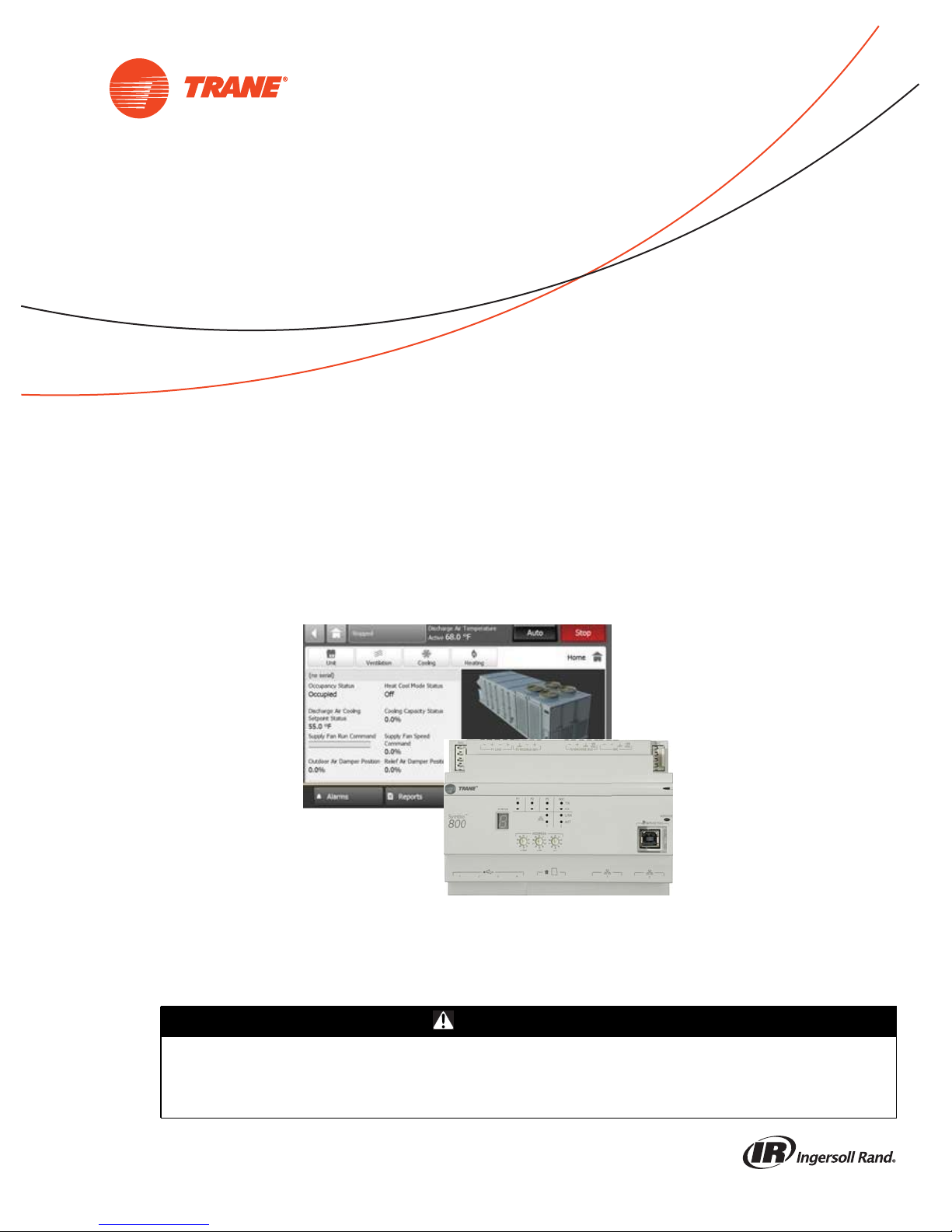
IntelliPak™ with Symbio™ 800, 20 to 75 Ton
with the Tracer®TD7 Display
Only qualified personnel should install and service the equipment. The installation, starting up, and servicing
of heating, ventilating, and air-conditioning equipment can be hazardous and requires specific knowledge and
training. Improperly installed, adjusted or altered equipment by an unqualified person could result in death or
serious injury. When working on the equipment, observe all precautions in the literature and on the tags,
stickers, and labels that are attached to the equipment.
December 2018
SAFETY WARNING
RT-SVP011A-EN
Page 2
Introduction
Warnings, Cautions, and Notices
Safety advisories appear throughout this manual as required. Your personal safety and the proper
operation of this machine depend upon the strict observance of these precautions.
The three types of advisories are defined as follows:
WARNING
CAUTIONs
NOTICE
T
Indicates a potentially hazardous situation which, if not avoided, could result in
death or serious injury.
Indicates a potentially hazardous situation which, if not avoided, could result in
minor or moderate injury. It could also be used to alert againstunsafepractices.
Indicates a situation that could result in equipment or property-damage only
accidents.
WARNING
Proper Field Wiring and Grounding Required!
Failure to follow code could result in death or serious injury. All field wiring MUST be
performed by qualified personnel. Improperly installed and grounded field wiring poses FIRE
and ELECTROCUTION hazards. To avoid these hazards, you MUST follow requirements for field
wiring installation and grounding as described in NEC and your local/state electrical codes.
Failure to follow code could result in death or serious injury.
WARNING
Personal Protective Equipment (PPE) Required!
Failure to wear proper PPE for the job being undertaken could result in death or serious injury.
Technicians, in order to protect themselves from potential electrical, mechanical, and chemical
hazards, MUST follow precautions in this manual and on the tags, stickers, and labels, as well
as the instructions below:
• Before installing/servicing this unit, technicians MUST put on all PPE required for the work
being undertaken (Examples; cut resistant gloves/sleeves, butyl gloves, safety glasses, hard
hat/bump cap, fall protection, electrical PPE and arc flash clothing). ALWAYS refer to
appropriate Material Safety Data Sheets (MSDS)/Safety Data Sheets (SDS) and OSHA
guidelines for proper PPE.
• When working withor around hazardous chemicals, ALWAYS refer to the appropriate MSDS/
SDS and OSHA/GHS (Global Harmonized System of Classification and Labelling of
Chemicals) guidelines for information on allowable personal exposure levels, proper
respiratory protection and handling instructions.
• If there is a risk of energized electrical contact, arc, or flash, technicians MUST put on all PPE
in accordance with OSHA, NFPA 70E, or other country-specific requirements for arc flash
protection, PRIOR to servicing the unit. NEVER PERFORM ANY SWITCHING,
DISCONNECTING, OR VOLTAGE TESTING WITHOUT PROPER ELECTRICAL PPE AND ARC
FLASH CLOTHING. ENSURE ELECTRICAL METERS AND EQUIPMENT ARE PROPERLY RATED
FOR INTENDED VOLTAGE.
© 2018 Ingersoll Rand All rights reserved RT-SVP011A-EN
Page 3

Copyright
This document and the information in it are the property of Trane, and may not be used or
reproduced in whole or in part without written permission. Trane reserves the right to revise this
publication at any time, and to make changes to its content without obligation to notify any person
of such revision or change.
Trademarks
All trademarks referenced in this document are the trademarks of their respective owners.
Agency Listings and Compliance
The European Union (EU) Declaration of Conformity is available from your local Trane® office.
Revision History
New
Introduction
RT-SVP011A-EN 3
Page 4

Table of Contents
Introduction ......................................................6
Hardware ...................................................... 6
Touchscreen Guidelines .......................................... 6
Dimensions .................................................... 7
Specifications and Agency Compliance ............................. 8
Controller and Service Tool Requirements ........................... 8
Supported Languages ............................................ 9
Screen Overview ............................................... 10
Alarms ..........................................................13
Active Alarms ................................................. 13
Alarm Icons ................................................... 14
Sorting Alarms ................................................ 15
Configuring Alarms ............................................. 15
Communication ............................................... 6
Screen Characteristics .......................................... 6
Tracer TU ....................................................8
WebUI ...................................................... 8
Top Display Area ............................................. 10
Main Display Area (Home Screen) ............................... 11
Bottom Display Area .......................................... 11
Viewing Active Alarms ........................................ 14
Reports .........................................................17
Custom Reports ................................................ 17
Creating a Custom Report ..................................... 17
Editing a Custom Report ....................................... 19
All Points Report ............................................... 20
Points Overrides ............................................... 21
Binary Overrides ............................................. 22
Multistate Overrides .......................................... 23
Analog Overrides ............................................. 23
Setting Up a Temporary Override ............................... 24
............................................................. 24
Override Summary ............................................. 24
About ........................................................ 25
Expansion Modules ............................................. 27
TGP2 Programs ................................................ 29
Data Logs ..................................................... 29
Using the Trend Viewer ......................................... 30
Data Graphs .....................................................31
4 RT-SVP011A-EN
Page 5

Table of Contents
Creating a Data Graph .......................................... 31
Settings ......................................................... 36
Control Settings ................................................ 36
Equipment Settings ............................................. 37
Unit Settings ................................................ 37
Feature Settings .............................................. 37
Manual Overrides ............................................ 37
Display Settings ................................................ 38
Display Preferences ........................................... 38
Language ................................................... 41
Date and Time ............................................... 42
Clean Touchscreen ........................................... 43
Schedules ..................................................... 43
Optimal Start/Stop ............................................ 44
Exceptions and Calendars ..................................... 44
Creating a Schedule .......................................... 44
The Tools Menu ................................................ 45
Backup and Restore ........................................... 45
Programs ................................................... 46
System Logs ................................................ 46
Recent Usage ................................................ 46
BACnet Information ........................................... 46
Configuring Basic Settings for the Symbio 800 ...................... 46
Regional Specifications ........................................ 47
Symbio 800 System Units ..................................... 47
Identification and Communication ............................... 47
USB Ports and microSD ....................................... 48
Licensing ................................................... 48
Configuring Additional Settings .................................. 49
Defaults for User Preferences ...................................49
Application Defaults .......................................... 49
SMTP Settings ............................................... 50
Priority Levels ............................................... 50
Login Page .................................................. 51
Troubleshooting ..................................................52
Identifying and Diagnosing Issues ................................. 52
Notes ...........................................................85
RT-SVP011A-EN 5
........................................................... 83
TD7 Automatic Rediscover and Automatic Hardware Reboot ........ 83
Page 6

Introduction
The purpose of this guide is to assist you in installing, programming, and operating with the
TracerTD7 Display and the Web UI, which interacts with the unit controls. This guide describes how
to access the screens and the types of information that appear on the screens.
The Tracer TD7 display is mounted to the unit and allows you to view data and make operational
changes to the equipment.
The Web UI is a built in service tool that allows users to set up, operate, and troubleshoot the
equipment.
Hardware
The Tracer TD7 is a durable factory-mounted touch screen display that is designed to operate in
both indoor or outdoor environments. The TD7 display utilizes a standard 75mm VESA mounting
pattern for installation in a Trane Large enclosure. Alternatively, it can be installed with a usersupplied VESA mount.
Communication
A separate Ethernet cable provides communication between the Tracer TD7 display and the unit
controller.
Screen Characteristics
The 7-inch WVGA 800 x 480 resolution touch-sensitive color screen is backlit, which enables
viewing in poor light conditions including outdoor usage (with the exception of direct sunlight).
Touchscreen Guidelines
The touch screen registers the downward pressure of a touch. Light, quick, yet deliberate touches
are most effective. Touching with more pressure has no effect.
Recommended tools to use:
• finger
• thumb
• pencil eraser
Do not use:
• a screwdriver
• a pen
• a pencil point
• any other sharp or pointed object that might scratch the screen surface
6 RT-SVP011A-EN
Page 7
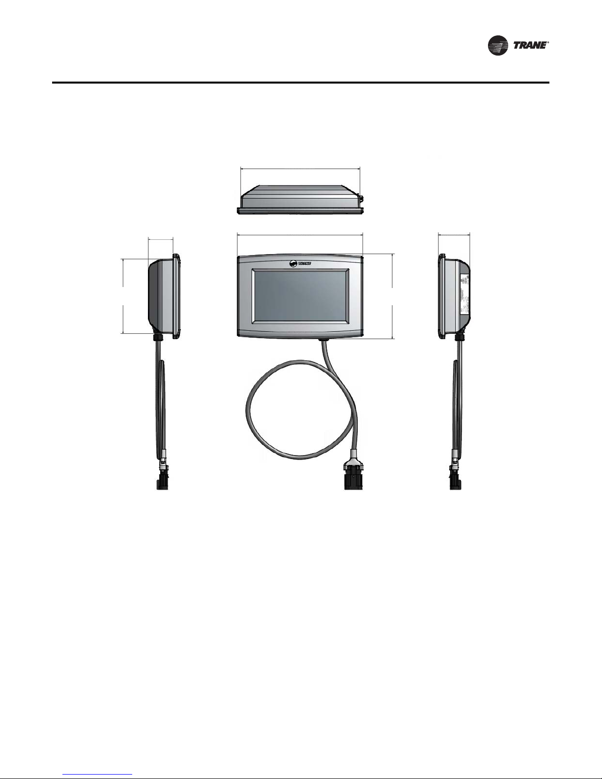
Dimensions
Introduction
7.9 in. (200.7 mm)
1.7 in. (41.9 mm)
5.5 in. (139.9 mm)
8.3 in. (211.6 mm)
Note: The power cable is permanently attached to the
TD7 display. The power connector provides
strain relief and protection from the elements.
2.1 in. (53.2 mm)
6.3 in. (158.8 mm)
RT-SVP011A-EN 7
Page 8
Introduction
Specifications and Agency Compliance
Specification
Input power: 24 Vac +/- 15%, 21 VA, 50 or 60 Hz
Storage temperature:
Operating temperature:
Mounting weight:
Environmental rating (enclosure): IP56 (dust and strong water protected) with use of an optional Sealed Ethernet Cable
Agency Compliance
• UL916 PAZX, Open Energy Management Equipment
• UL94-5V, Flammability
• FCC CFR Title 47, Part 15.109: Class A Limit, (30 MHz—4 GHz)
• CE EMC Directive 2004/108/EC
• CE EMC Directive 2004/108/EC
-67°F to 203°F (-55°C to 95°C)
Humidity: Between 5% and 100% (non-condensing)
Temperature: -40°F to 158°F (-40°C to 70°C)
Humidity: Between 5% and 100% (non-condensing)
Mounting surface must support 1.625 lb (0.737 kg)
Mounting Type: VESA (75 mm x 75 mm)
Controller and Service Tool Requirements
Tracer TU
Tracer TU Service Tool Version 10.2 or higher is only required for TGP2 and modifications done in
the field.
Note: Tracer TU is not needed for normal operation. If you need to perform configuration changes,
add new features, or customize the operation of the equipment, contact your local Trane
office.
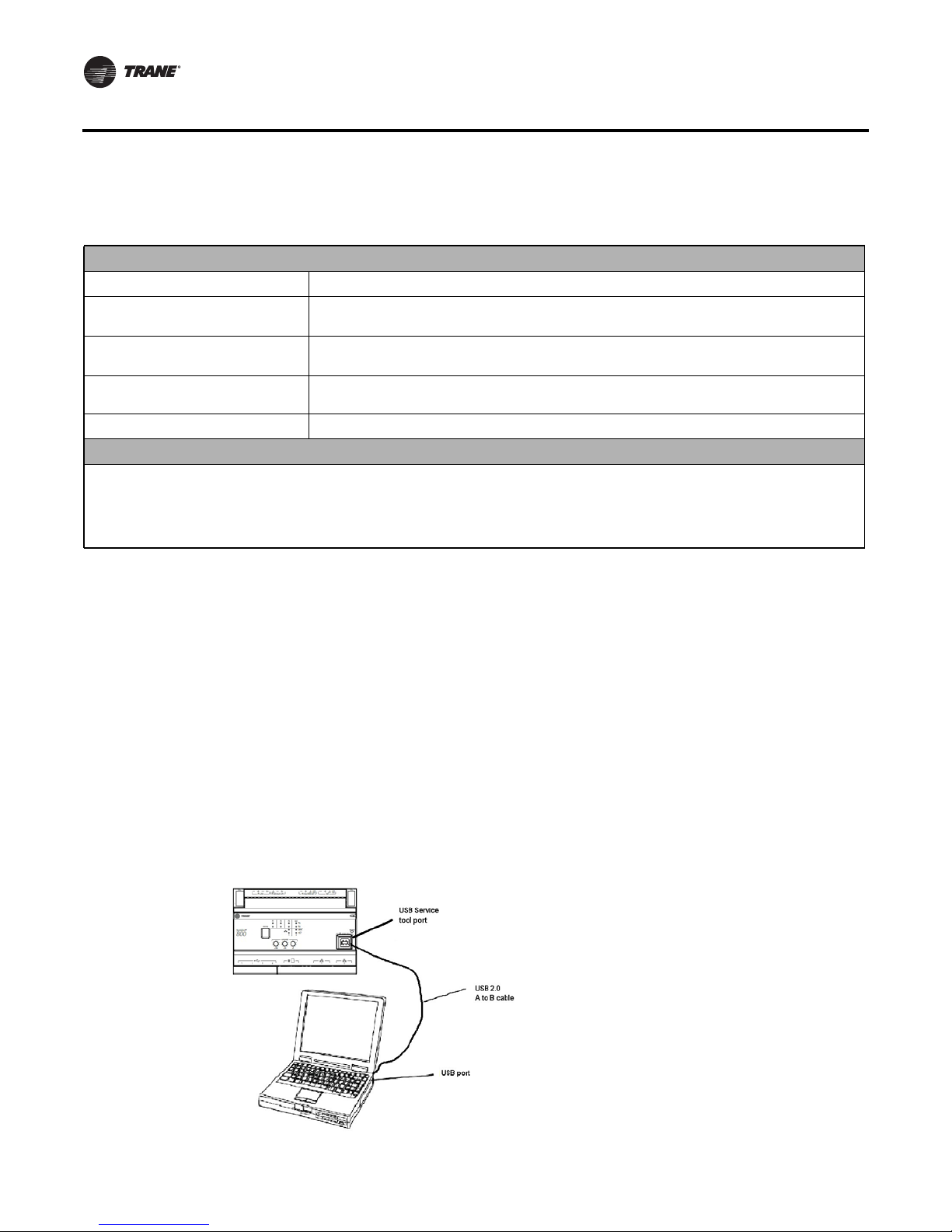
Web UI
To perform firmware updates, setup communication protocols, backup and restore, scheduling,
and create users or custom trend views connect using Web UI:
1. Connect a laptop to the USB service tool port using a USB 2.0 A to Be cable.
2. Open a web browser and connect to http://198.80.81.1 to access Web UI.
Figure 1. Web UI connection
8 RT-SVP011A-EN
Page 9

Supported Browsers for Tracer Symbio Web UI
Microsoft Windows 7:
• Internet Explorer 11 (limited support)
• Mozilla Firefox (most recent version)
• Google Chrome (most recent version)
Microsoft Windows 8.1: (no support)
Microsoft Windows 10:
• Internet Explorer 11 (no support)
• Microsoft Edge (most recent version)
• Mozilla Firefox (most recent version)
• Google Chrome (most recent version)
Apple Mac OS (latest version -1)
• Mozilla Firefox (most recent version)
• Google Chrome (most recent version)
• Safari (most recent version)
Introduction
Creating a New User in Web UI
Note: For more detailed instructions on creating a new user, click the help icon in the global
navigation bar within Web UI.
To create a new user:
1. From the global navigation bar, select Admin > Users.
2. Click the Create User button.
3. Enter the user’s personal information, and click Next.
4. On the Preferences page, determine how certain attributes on the Symbio 800 user interface
will display. Click Next.
5. On the Data Display Units Preference page, determine the unit type in which data will be
displayed. Click Next.
6. On the Data Display Units Preference page, determine the preferred display units. Click Next.
7. On the summary page, review your selections. Click Finish to save the new user.
Supported Languages
The TD7 display supports built-in languages:
• English
• French (Canadian)
• Spanish (Latin American)
RT-SVP011A-EN 9
Page 10
Introduction
Screen Overview
There are three distinct areas on the TD7 screens:
• Top display area
• Main display area
• Bottom display area
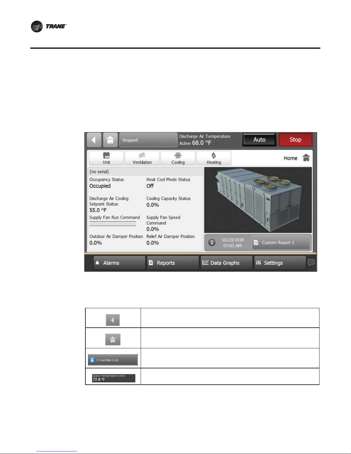
Figure 2. Tracer TD7 display screen
Top display area
Main display area
Bottom display area
Top Display Area
The Back button, when touched, returns to the previous screen visited.
The Home button, when touched, navigates to the All Points Report by default. Home Can
be configured to display any of the three custom reports, All Points Report, All Points in
Override Report, Alarms, or custom graphic. See “Display Preferences,” p. 43.
The Overrides Summary button provides an at-a-glance view of how many user overrides
exist and provides a link to the Override Summary report.
The Space Temperature Active or Discharge Air Temperature Active, depending on
configuration is displayed in the header Data Area.
10 RT-SVP011A-EN
Page 11
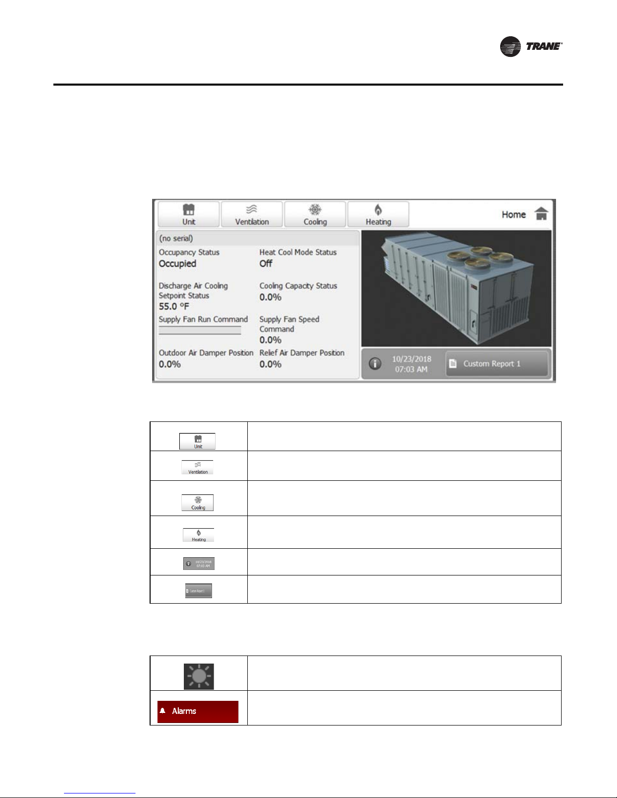
Main Display Area (Home Screen)
The Home screen is an overview of the unit and its operation. High-level status information is
presented so that a user can quickly understand the mode of operation of the unit and navigate
quickly to other areas of the display for more detail.
Figure 3. Tracer TD7 Main display area of home screen
Introduction
Main display are buttons:
Bottom Display Area
The bottom display area contains functional buttons that provide a link to the appropriate screen.
Touch this button to view the status of unit features. Setpoints, Capacities, and damper
positions.
Touch this button to view the status of ventilation components.
Touch this button to view the status of the cooling.
Touch this button to view the status of heating components.
Touch this button to access the adjust the date and time. Touch the information icon to
view hardware part numbers and software version numbers.
Touch this button to access custom reports.
Screen brightness settings: Touch this icon to open the brightness screen.
Touch this button to open the Alarms screen. When an alarm is present, this button will
flash red.
RT-SVP011A-EN 11
Page 12
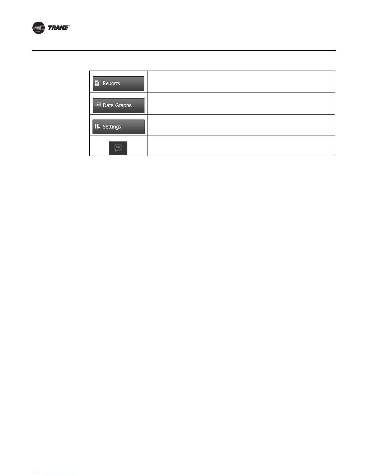
Introduction
Touch this button to navigate to the Reports screen.
Touch this button to open the Data Graphs screen to view and/or edit data logs in
graphical format.
Touch this button to open the Settings screen, which contains options for manual
controls, Feature settings, Binding, Unit Settings, and display settings.
Language selection: Touch this icon to select a language that will be displayed on all
screens.
12 RT-SVP011A-EN
Page 13
Alarms
Alarms appear on the Tracer TD7 display immediately upon detection. Touch the Alarms button in
the bottom display area to view the Alarms screen.
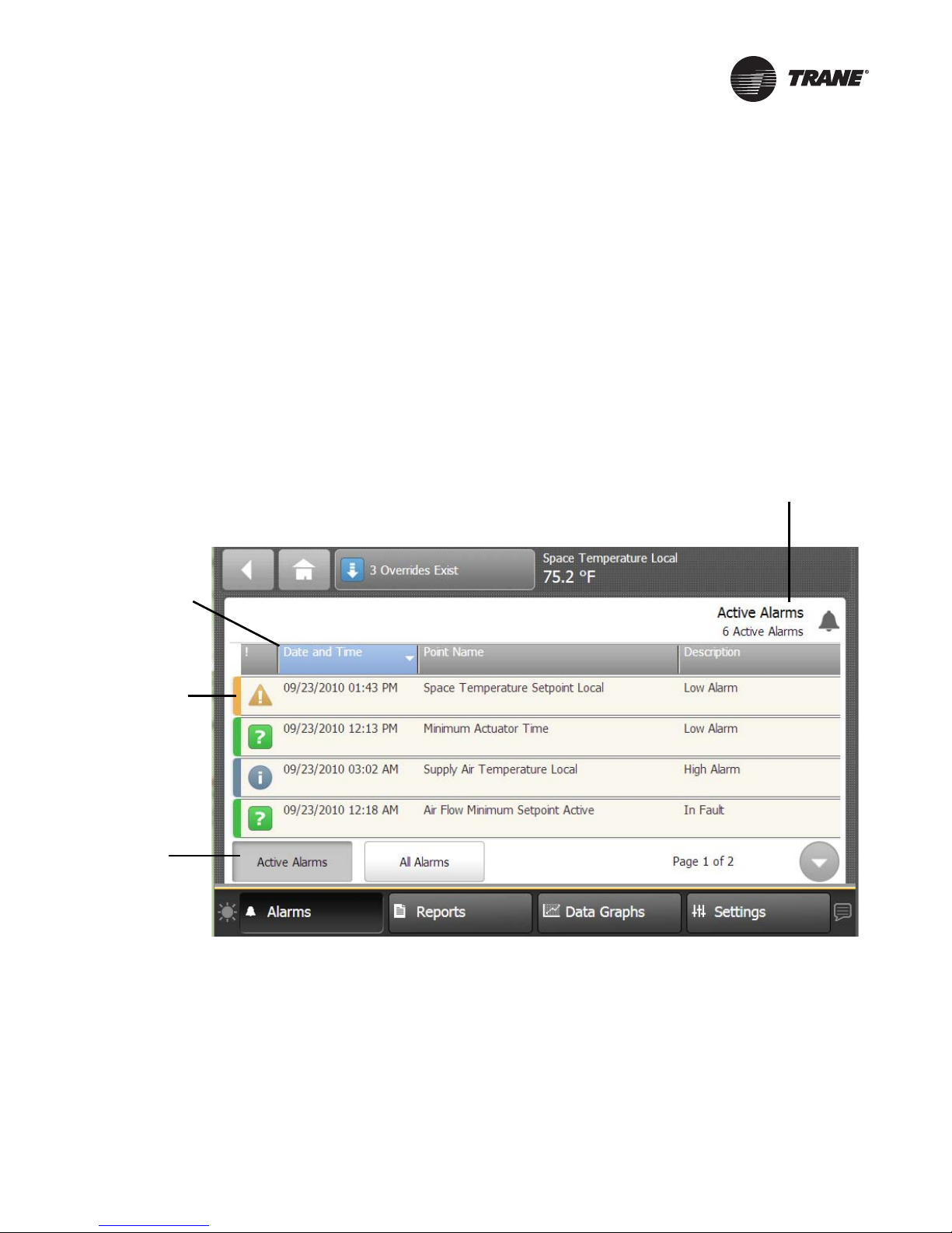
Active Alarms
Figure 4 shows the Active Alarms screen and commonly used functions. Configuration is not
required in order for points in alarm to appear in the Active Alarms screen. When the alarm clears
and the point returns to normal, the alarm will automatically be removed from the list.The number
of active alarms is displayed in the top right portion of the screen. When an active alarm is present,
the alarm button at the bottom of the screen will flash.
The Alarms screen defaults to Active Alarms. The Active Alarms button has a shaded appearance
which indicates that you are viewing active alarms.
Figure 4. Active Alarms screen
Sortable
Columns
Number of Active Alarms
Alarm Severity
Active Alarms
Button
Figure 5.
On the Alarms screen, touch the Alarms button to view all alarms, commonly referred to as the
event log. For the alarms to appear on the TD7 display, the point must have an alarm notification
class selected. Additionally, the point must have entered the appropriate notification (In Alarm,
When Failed, Return to Normal, or the notification class set to a value other than None).
RT-SVP011A-EN 13
Page 14
Alarms
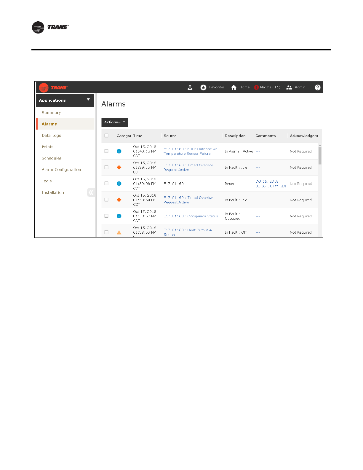
Figure 6. Web UI Alarms screen
Viewing Active Alarms
• Active alarms: These are alarms that require attention. All alarms that are currently active
appear when you view this category. Active alarms are not reset by way of the display. Active
alarms will clear automatically when the condition causing the alarm is removed.
• Historic alarms: Touch this button to view previous alarms.
Alarm Severity
A color-code icon representing the severity of each alarm is shown under the severity ( ! ) column.
For a description of the five alarm icons, see Table 1, p. 15.
Sortable Alarms
You can sort active alarms by touching one of the column headers. Choose to sort by
severity(!),date and time, point name, or description.
Reset Alarms
Touch this button to clear alarm that are no longer active.
Alarm Icons
Alarms icons appear in the left-most column of the alarms screen. They are identifiable by their
shape and color.
14 RT-SVP011A-EN
Page 15
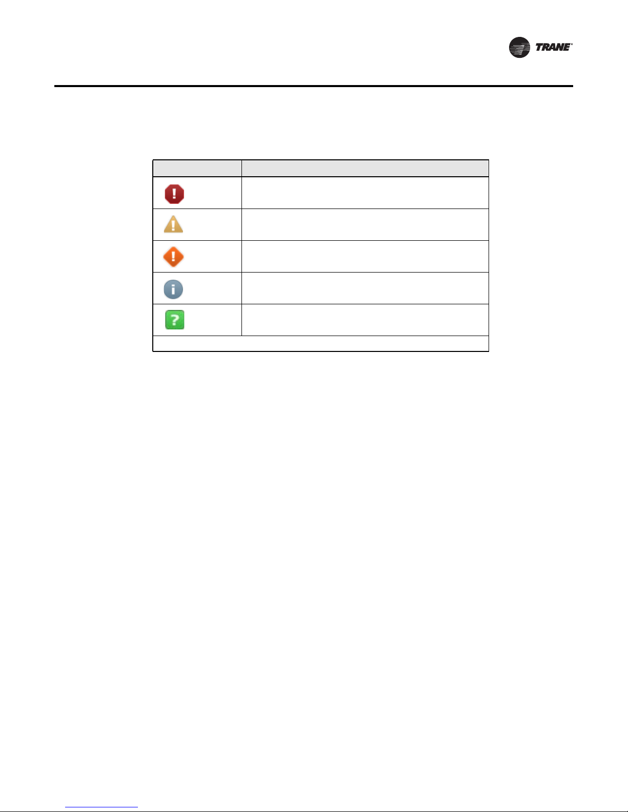
Table 1. Alarm icons
Active Alarm Icons Notification Class
Critical
Service Required
Warning
Information
None
Note: Notifications classes are configured in point alarm settings section in Tracer TU.
Alarms
Sorting Alarms
To sort alarms by a category other than date and time, touch one of the other column headings in
the table. The column heading responds by changing to blue, and the alarms table re-sorts
according to the blue column heading. By touching the blue column heading again, the column will
change the sort direction.
• Severity (!): Active alarms are at the top, followed by the most severe, followed by the most
recent.
• Date and Time (the default sort): Most recent alarms are at the top.
• Point Name: Alphabetical sort based on the point name.
• Description: Alarms are sorted alphabetically by description.
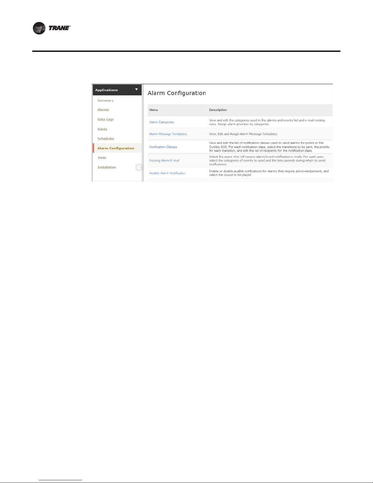
Configuring Alarms
In the web user interface, select Applications \ Alarm Configuration. From the Alarm
Configuration screen, you can view and edit alarm categories and routing, alarm message
template, and notification classes.
RT-SVP011A-EN 15
Page 16
Alarms
Figure 7. Web UI Alarm Configuration screen
16 RT-SVP011A-EN
Page 17
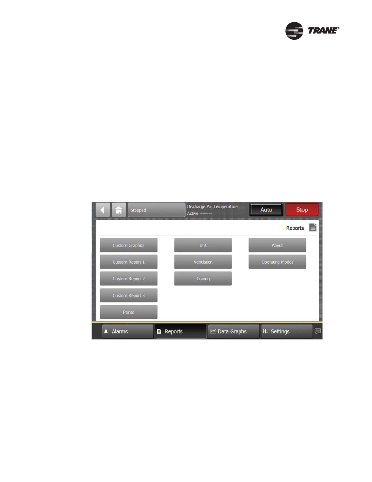
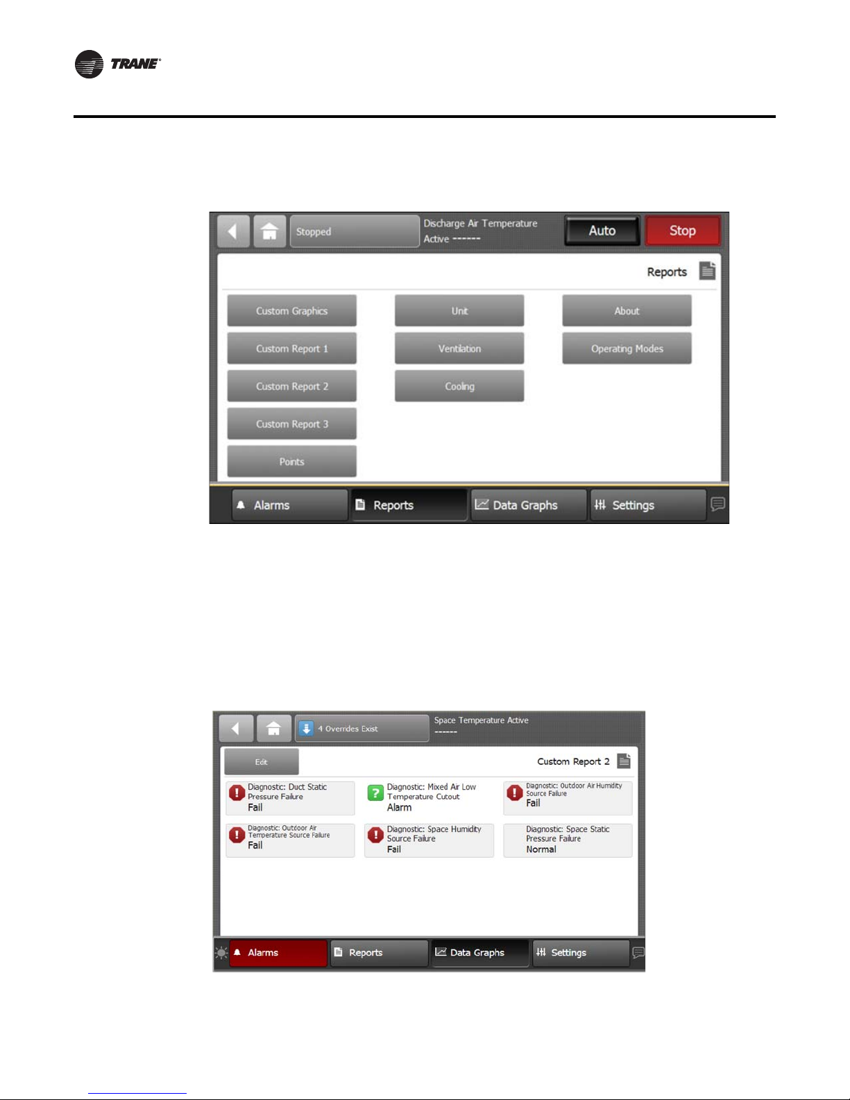
Reports
You can use the Tracer TD7 Display to view a variety of reports and create and edit custom reports.
Touch the Reports button in the bottom display area to view the Reports screen. The Reports screen
contains the following buttons:
• Custom Report 1
• Custom Report 2
• Custom Report 3
• Points
• Override Summary
• All Points Report
• About
• Expansion Modules
• TGP2 Programs
Figure 8. Reports screen
Custom Reports
You can create up to three custom reports using the Tracer TD7 Display. Reports may contain all
nine point types. A maximum of 36 pieces of data is allowed per custom report. Available reports
are labeled Custom Report 1, 2, or 3.
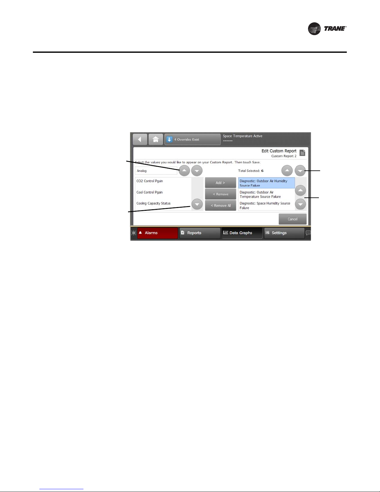
Creating a Custom Report
1. Navigate to the Reports screen, then touch one of the three custom report buttons.
The Custom Report (1, 2, or 3) screen appears.
2. Touch the Edit button.
The Edit Custom Report screen appears (Figure 9).
RT-SVP011A-EN 17
Page 18
Reports
Figure 9. Creating a custom report
3. Use the up and down arrow buttons to select a point type. Add items by touching the item that
is highlighted blue, then touch the Add button.
4. Continue adding values to your report. When you are finished, touch the Save button.
The Custom Report screen, populated with your selected values, appears (Figure 10).
To view the items in the selected list, touch a value in this list and use the up and down arrows
to the right of the list. To change the location of an item in the list, select the item and then use
the up and down arrows above the table to move the items.
Figure 10. New custom report screen
18 RT-SVP011A-EN
Page 19
Editing a Custom Report
n
1. Touch Reports to view the Reports screen.
2. Touch the report that you want to edit.
Follow steps 2 through 4 in “Creating a Custom Report,” p. 17. to complete your edits.
Figure 11. Editing a custom report
Up and down
arrows:
moves 1
space per
touch
Reports
Up and dow
arrows:
moves 1
space per
touch
Up and down
arrows:
moves 2
spaces per
touch
Up and down
arrows:
moves 2
spaces per
touch
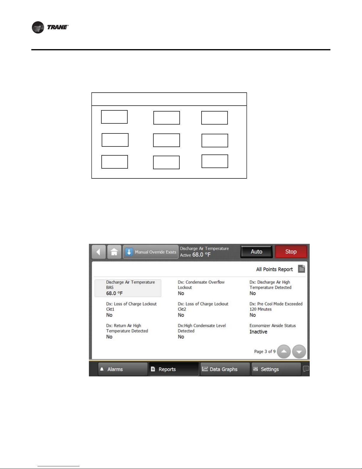
Changing the Order of Items in a Custom Report
Items in a custom report can be rearranged according to personal preference by using the editing
tools as described in Editing a Custom Report.
For example, you created the custom report shown in Figure 10, p. 18, but would prefer to move
item “Diagnostic: Space Static Pressure Failure” to the top left portion of the report.
To change the order for the example described above:
1. Touch the Edit button on the Custom Report screen.
2. Use the arrow buttons to locate the item to be reordered. When located, touch the item which
will then be highlighted blue (see
3. Use the arrow buttons to move the highlighted item to the top of the list (number 1 position).
4. Touch Save. You will be returned to the Custom Report screen, where the reordering changes
now appear.
Note: On the TD7 display, report items are ordered from left to right with the first item appearing
at the top left portion of the screen. Up to nine items can appear on each Custom Report
screen with a maximum of 4 screens and 36 items per report.
The model in Figure 12 depicts a custom report screen with the first nine items displayed on the
screen. Use this model to accurately reorder items in your custom reports.
Figure 11).
RT-SVP011A-EN 19
Page 20
Reports
Figure 12. Custom Report (order of items)
Custom Report
All Points Report
Touch the All Points Report button to view the All Points Report screen, which contains all
configured points for the unit controller. Use the up and down arrows located at the right most
bottom of the screen to page up or down.
Figure 13. All points report screen
1
4
7
23
5
8
6
9
20 RT-SVP011A-EN
Page 21
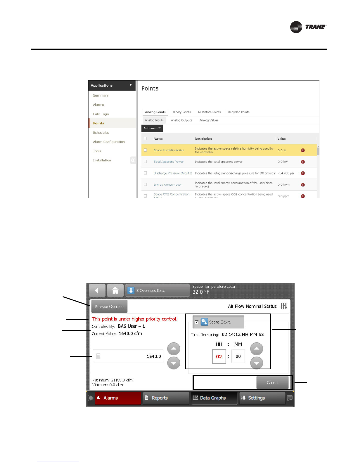
Figure 14. Web UI Points
Reports
Points Overrides
Point Overrides are used to allow control of values, such as setpoints used for the operation of the
equipment. These can be time based or persist until they are released.
From the Point Override screen you can perform overrides, set them to expire in a user-defined
interval, or release a point that is currently overridden. All Point Override screens, (analog, binary,
or multistate), are comprised of the same basic components.
Figure 15. Point Override screen components
Release
Override
See Note
“Releasing an
Override.”
Override
Status Area
Override Value
Setting Area
Temporary
Override Area
Action
Area
RT-SVP011A-EN 21
Page 22
Reports
Override Status Area
This area shows who is controlling the point, followed by the active priority level and the current
value of the point. If security is enabled, the name of the user that performed the override will be
shown in the Controlled By field. If security is disabled, “Front Panel” is displayed for all overrides
performed by the TD7 display.
Override Value Setting Area
This area contains buttons that when pressed, change the override status. The button that is active
has a shaded appearance in color. The exception is analog points, which require manually entering
a value.
Temporary Override Area
This area allows you to set up a temporary override.
Action Area
This area allows you to apply, save, or cancel edits made to the point override.
Releasing an Override
Touch the Release Override button to release the current override. This action returns you to the
Override Summary screen.
Note: If a point is under a higher priority control , you can still proceed with releasing the override.
However, it will not take effect until the higher priority level is removed in Tracer TU, Tracer
SC, or Tracer ES.
Binary Overrides
The Binary Override screen provides buttons with point state text that is used to set the current
value. Multistate overrides with four or fewer states have similar screen functions as the binary
override screen.
Touch a button in the override setting area to select a state. Touch the Apply or Save button to retain
your changes.
Figure 16. Binary Override screen
22 RT-SVP011A-EN
Page 23
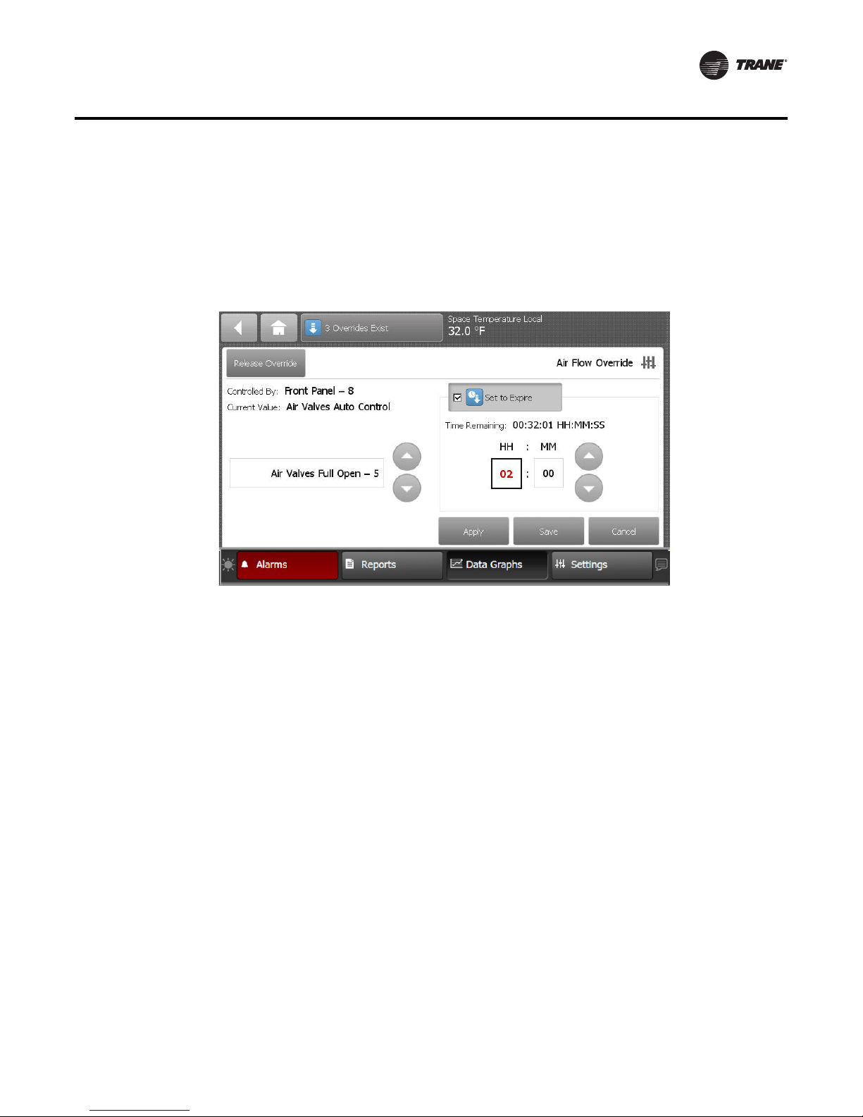
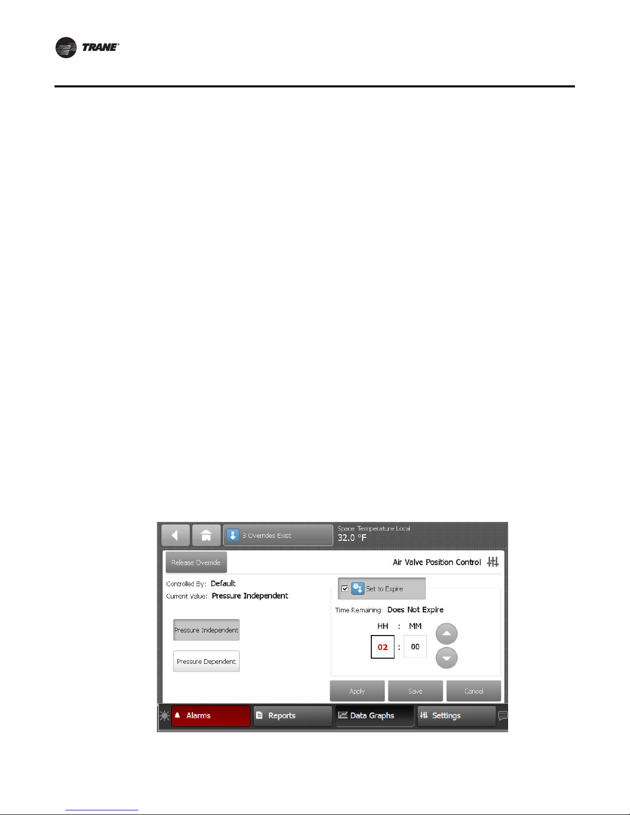
Multistate Overrides
Multistate override screens that contain five or more items will contain up and down arrow buttons
in the Override setting area.
Use the up and down arrow buttons to select a state. Touch the Apply or Save button to retain your
changes.
Figure 17. Multistate override screen (five or more states)
Reports
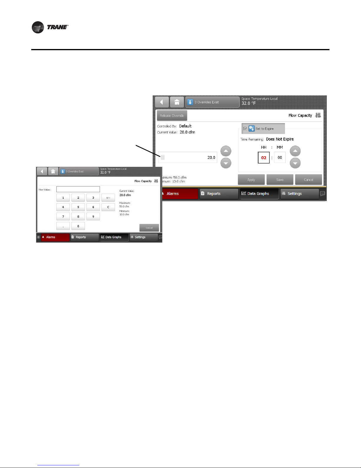
Analog Overrides
The Analog Override screen contains up and down arrows in the Override setting area, as well as
a keypad icon that when touched, opens the Analog Keypad.
Use the up and down arrow buttons to select a value. Touch the Apply or Save button to retain your
changes. To manually enter a value, touch the keypad icon.
RT-SVP011A-EN 23
Page 24
Reports
Figure 18. Displaying the analog keypad screen
Touch the keypad icon to open the Analog
keypad screen.
Enter a value by tapping the numerals on the
keypad. Touch Enter to save and return to the
Override screen.
Keypad Icon
Analog Keypad Screen
Setting Up a Temporary Override
You can set up a temporary override by using the buttons in the Temporary Override area. The
default for temporary overrides is 2 hours 0 minutes. The maximum duration for a temporary
override is 99 hours 59 minutes. If more time is needed, consider setting up a permanent override.
1. Touch the Set to Expire button.
A check mark appears in the check box, the override icon becomes blue, and the Time
Remaining area appears.
2. Touch either the hours (HH) or minutes (MM) button, then use the up and down arrows to set
the override.
The HH and MM buttons, when pressed change by one increment. Press down on the buttons
to accelerate. A second touch of the (HH) or (MM) buttons will open the Analog keypad screen.
Touch the Apply or Save button to set the temporary override.
Override Summary
The TD7 has a built in override summary report that can be accessed in one of two ways:
The preferred method is to access the report by touching the Override Summary button located in
the top display area of each TD7 screen.
An alternate method is to touch the Override Summary button on the Reports screen.
24 RT-SVP011A-EN
Page 25
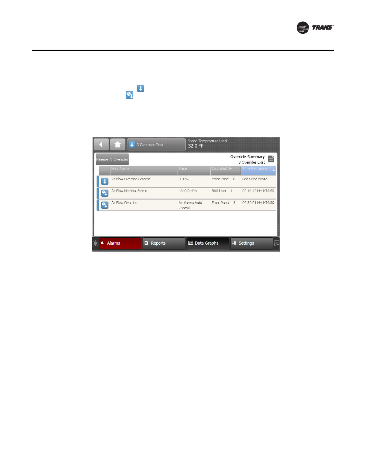
Reports
The Override Summary screen contains all active overrides. Columns are sortable and
automatically default to Time Remaining.
The override icon ( ) indicates that a point override is in effect indefinitely. The temporary
override icon ( ) indicates that an override will expire after a specified duration.
To release all overrides in the list, touch the Release All Overrides button (only points that are
controlled at priority level 8 will be released). Touch anywhere in a point row to navigate to the
corresponding Point Override screen.
Figure 19. Override summary screen
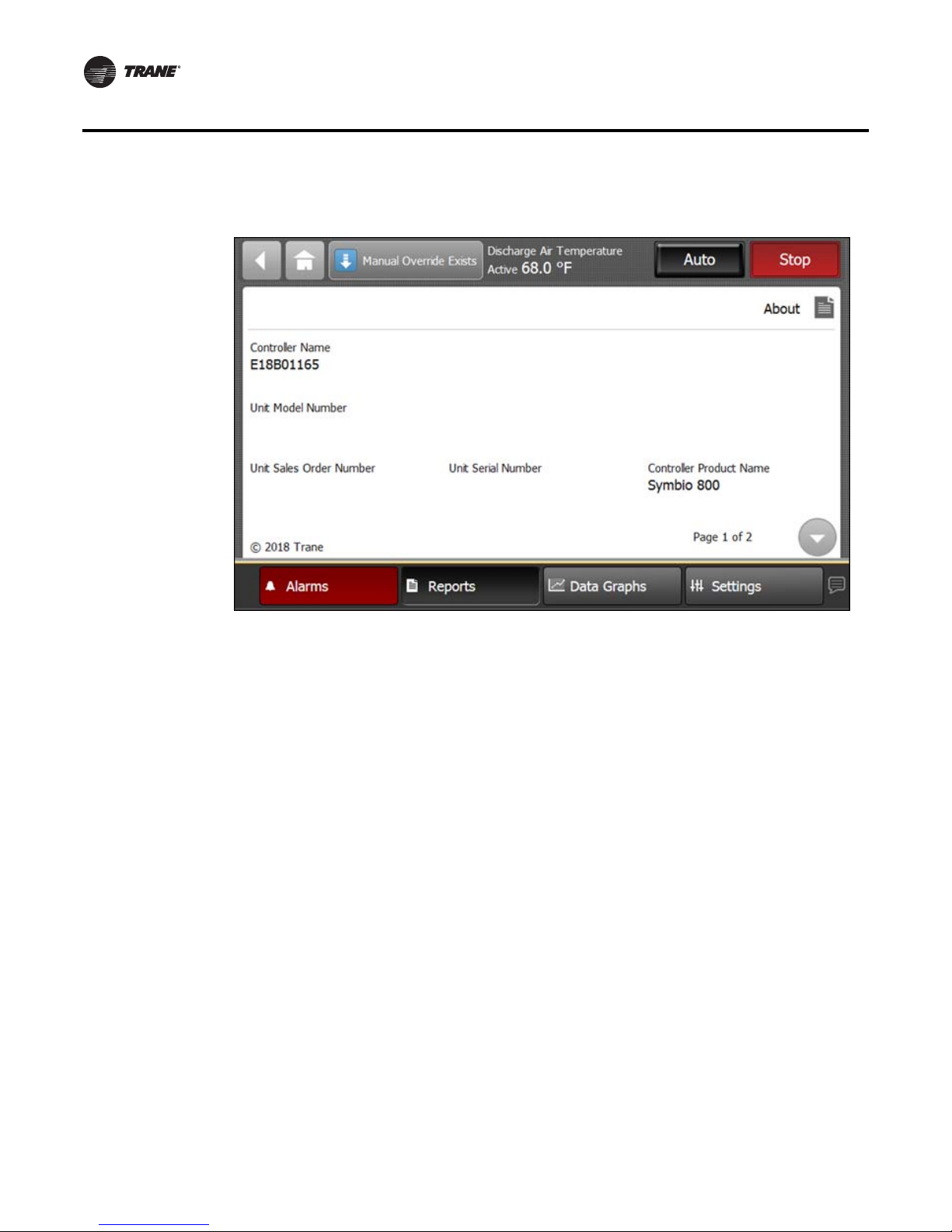
About
Touch the About button to view the About screen. View information about the unit controller and
the TD7 display to which it is connected. Touch the arrow button to scroll to the next screen.
RT-SVP011A-EN 25
Page 26
Reports
Figure 20. About screen
Controller Name
This is the name that was assigned to the Symbio 800.
Unit Model Number
This is the model number of the IntelliPak/equipment on which the Symbio 800controller is
installed. This value is typically entered in the factory, but can be entered in the controller.
Unit Sales Order Number
This is the order number for the equipment that the Symbio800 controller is controlling. This
number is typically entered at the factory, but can be entered in the controller.
Unit Serial Number
This number applies to the piece of equipment that the Symbio 800 controller is controlling. This
number is typically entered at the factory, but can be entered in the controller.
Controller Product Name
The controller product name will always be Symbio 800.
Controller Hardware Part Number
This is the part number for the Symbio 800 controller.
26 RT-SVP011A-EN
Page 27
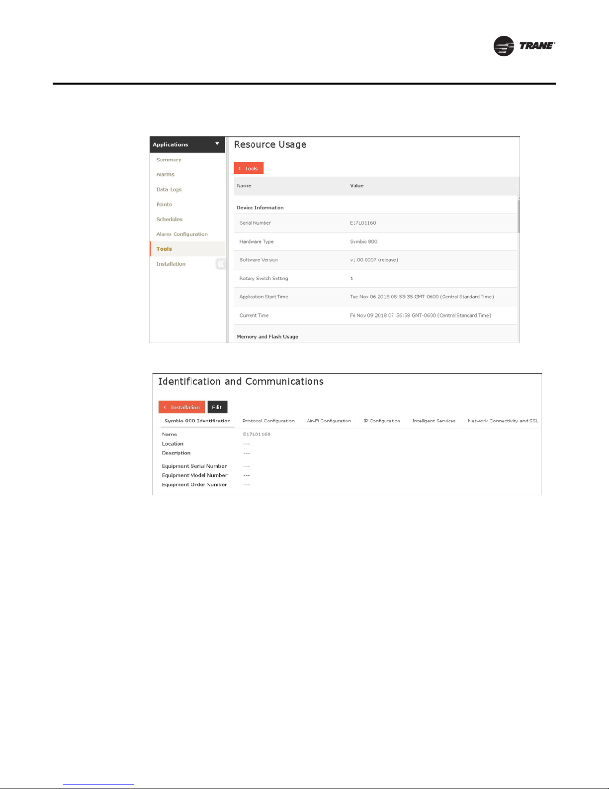
Figure 21. Web UI Resource Usage
Figure 22. Web UI Identification and Communications
Reports
Expansion Modules
Touch the Expansion Module button to view the Expansion Modules screen. If expansion modules
have been installed, they will appear in Expansion Modules screen (Figure 23).
RT-SVP011A-EN 27
Page 28

Reports
Figure 23. Expansion modules screen
Expansion module screen columns:
Address — This is the rotary address of the defined or discovered expansion module.
Status — Under normal conditions, OK will display in this column. If not refer to “Tracer XM30,
XM32, XM70, and XM90 Expansion Modules IOM,” BAS SVX46-EN.
Hardware part number — This is the part number for the expansion module.
Software part number — This is the version number of the software running in the expansion
module.
28 RT-SVP011A-EN
Page 29

TGP2 Programs
Touch the TGP2 Programs button to view the TGP2 Programs screen. All TGP2 programs that have
been installed on the controller appear here. The program name, status, run type, and interval for
each program is provided. Interval is the scheduled run interval for the program and is displayed
in HH:MM:SS. If the run type is Startup or Event, the interval field will display all zeros.
Figure 24. TGP2 Programs screen
Reports
Data Logs
Figure 25. Web UI TGP2 Programs
Data Logging, also referred to as trending, records in real-time the value of a data point in the
system and the time at which the value was recorded.
By default, Symbio 800 automatically generates system-created data logs (for equipment and
standard applications) on a 15-minute interval and then stores that data for seven days. Data
storage is a continuous window where only the most recent seven days of data are stored. Data
older than seven days is discarded in
RT-SVP011A-EN 29
Page 30

Reports
order to make room for the newest data.
A list of data logs can be accessed by clicking Data Logs from the left navigation menu. From this
page you can take action on a data log, such as comparing or exporting, by selecting one or more
data logs and then clicking the Actions button.
Figure 26. Web UI Data Logs
Using the Trend Viewer
The trend viewer displays trend data in a chart. The trend viewer supports a time comparison mode
that allows you to compare trend data at different points in time (day-to-day, month-to-month, yearto-year). A maximum of six data logs are supported (up to two data logs when time comparison
mode is enabled). A maximum of two types of dimensionality are supported on the left and right
y axis. Samples are plotted on a date/time scale on the x axis. Samples in fault (due to
communication loss) are not plotted and will result in an interpolation gap within the plotted line.
If all samples are in fault, no line will be displayed.
The trend viewer is available on the data logs tab of status pages for equipment and systems. To
view trends graphically, select up to six data logs from the Data logs page and then select View
datafrom the Actions button.
30 RT-SVP011A-EN
Page 31

Data Graphs
Data graphs allow users to view trend logs from the controller in graphical format on the TD7
Display. Up to eight data graphs can be created with a maximum of four data logs per graph. Data
graphs are user-defined and can be edited by changing the scale on the left and right Y-axis and
choosing the line color.
Touch the Data Graphs button in the bottom display area to view the Data Graphs screen
(Figure 27). The Data Graphs screen contains eight buttons that allow you to view and edit a
particular configuration.
Figure 27. Data Graphs screen
Creating a Data Graph
1. Navigate to the Data Graphs screen, then touch an available data graph button.
The Custom Data Graph screen appears.
2. Touch the Edit Data Graph button.
The Edit Data Graph screen appears (Figure 28, p. 32).
RT-SVP011A-EN 31
Page 32

Data Graphs
Figure 28. Edit Data Graph screen
3. Touch the Add/Remove button to add values to the custom data graph.
The Add/Remove screen appears.
4. Use the arrow buttons to select a datalog type: analog, binary, or multistate, which then
populates the box directly below.
5. Select the values, then touch the Add button (up to four selections are allowed).
6. Touch the Save button. The Edit Data Graph screen appears, which reflects the selected values.
Figure 29. Adding data logs to the custom graph
32 RT-SVP011A-EN
Page 33

Data Graphs
7. Use the Edit Data Graph screen to modify the data graph. Touch the Edit button that
corresponds with the value that you want to change. Only one value can be edited at a time.
Figure 30. Edit Data Graph screen (after values have been added)
8. From the Edit screen you can choose which Y-axis to display the value, a color, and whether or
not to show data samples. Touch the Save button when finished. Repeat the process with
remaining values.
Figure 31. Customizing the data graph
RT-SVP011A-EN 33
Page 34

Data Graphs
9. Touch the View Data Graph button to display the new graph (Figure 32).
Note: Depending on the sampling rate, the custom data graph may be empty for several hours.
You can make changes to the way data is presented on the graph at anytime. Touch the zoom-in
icon and zoom-out icon to either increase or decrease the viewable time frame. This action
also enables back and forward arrows that allow you to view data at various times of the day.
Figure 32. Viewing the data graph
Editing the Y-Axis
The default values on the right and left Y-axes can be changed according to your specifications.
1. Touch the Edit Y-Axis button located on the top portion of the Custom Data Graph screen.
The Edit Y-Axis screen appears.
2. Touch the Manually Select Range box for either the left or right Y-axis.
3. Touch the edit button next to one of the two value ranges.
The Keypad screen appears.
4. Select a new value and then touch Enter to save.
34 RT-SVP011A-EN
Page 35

Data Graphs
Figure 33. Repeat steps 2 through 4 until all preferred changes have been made. Editing the Y-Axis
RT-SVP011A-EN 35
Page 36

Settings
The Settings screen provides options for display settings, language, overrides and security.Touch
the Settings button in the bottom display area to view the Settings screen.
Three categories for settings appear on the screen:
• Control Settings
• Equipment Settings
• Display Settings
Figure 34. Settings screen
Basic
parameters for
unit operation
Turn on/off
features and
functions
Resets the
discharge air
setpoint
(discharge air
units only)
Control Settings
This category contains the LLID Binding.
36 RT-SVP011A-EN
Page 37

Figure 35. LLID Binding
Settings
Equipment Settings
Unit Settings
Unit Settings are the basic parameters for unit operation.
Feature Settings
Features Settings allows you to enable or disable features and functions.
Manual Overrides
Manual Overrides are temporary overrides that can be used to test equipment and features. The
override time is adjustable from1-78hours.
Navigate to the Manual Override screen by touching the Settings button, then the Manual Control
Settings button. From there select the appropriate unit or circuit level button.
RT-SVP011A-EN 37
Page 38

Settings
Figure 36. Manual Override screen
Override Status Area
This area shows who is controlling the point, followed by the active priority level and the current
value of the point. If security is enabled, the name of the user that performed the override will be
shown in the Controlled By field. If security is disabled, “Front Panel” is displayed for all overrides
performed by the TD7 display.
Override Value Setting Area
This area contains buttons that when pressed, change the override status. The button that is active
has a shaded appearance in color. The exception is analog points, which require manually entering
a value.
Display Settings
The selections in this category contain settings that affect the way in which information is displayed
on all of the TD7 display screens. From each screen, the current settings can be viewed. To change
a setting, touch the preferred value.
Display Preferences
Touch the Display Preferences button to open the associated screen (Figure 38). On this screen, all
available options to display information on the TD7 screens are available. There are two pages on
this screen, accessed by using the arrow button at the bottom of the screen.
38 RT-SVP011A-EN
Page 39

Figure 37. Web UI User Preferences
Figure 38. Display Preferences screen
Settings
Date Format
Touch the Date Format button to open the associated screen. Three options are available to display
the current date: MMDDYYYY, DDMMYYYY, and YYYYMMDD.
Date Separator
Touch the Date Separator button to open the associated screen. Three options are available to
display separators in the date format: None, Hyphen (-), or Slash (/).
Time Format
Touch the Time Format button to open the associated screen. Two options are available: 12-Hour
format and 24-Hour format (also referred to as “military time”).
Unit System
Touch the Unit System button to open the associated screen. Two options are available: SI (system
international) or IP (Inch-Pound).
RT-SVP011A-EN 39
Page 40

Settings
Number Format
Touch the Number Format button to open the associated screen. Two options are available: period
format (1000.0) or comma format (1000,0).
First Day of the Week
Touch the First Day of the Week button to open the associated screen. Specify the starting day for
the week when viewing schedules and adding events. Options available: Saturday, Sunday, or
Monday.
Brightness
Touch the Brightness button, or the brightness icon ( )located at the bottom left of each screen,
to open the associated screen. Screen brightness is measured in percentage. Use the keypad to
enter a new brightness number.
Backlight Timeout
Touch the Backlight Timeout button to open the associated screen. This value is measured in
minutes, with 30 being the maximum limit. Use the keypad to enter a backlight timeout value. This
value is the amount of time that the display will remain lit without activity. When the backlight times
out, users will be automatically logged off due to inactivity.
Header Data Point
Use the arrow button on the Display Preferences screen to advance to page 2. Touch the Header
Data Point button to open the associated screen. The Header Data Point appears in the top right
display area on all screens. Use the arrow buttons to scroll through the points. Click Add to move
the highlighted point to the right side of the screen(Figure 39, p. 40). Click Save.
Figure 39. Setting the header data point
Header data
point
Home Page
Use the arrow button on the Display Preferences screen to advance to page 2. Touch the Home Page
button to open the associated screen. This function allows you to choose what will display when
the home button is touched. Available options are: the All Points report, the Override Summary
Report, Active Alarms, any of the three Custom Reports, or any custom graphic.
40 RT-SVP011A-EN
Page 41

Figure 40. Home Page screen
Figure 41. Web UI Home Page
Settings
Language
Touch the Language button, or the language icon ( ) located at the bottom right of each screen,
to open the open the Language screen. Three languages are available and represented on the
selection buttons. Select a language that you want displayed on each TD7 screen and then touch
Save.
RT-SVP011A-EN 41
Page 42

Settings
Figure 42. Language screen
Figure 43. Web UI Login screen
Date and Time
Touch the Date and Time button to open the associated screen. To enter a new date or time, touch
the digit you want to change. When enabled for editing, the digit will appear red with a black border.
when finished, touch Apply or Save. Or,
tap the digit twice which opens the keypad screen where you can make date and time entries. When
finished, touch Enter; you will be returned to the Date and Time screen. Touch Apply or Save.
42 RT-SVP011A-EN
Page 43

Figure 44. Date and Time screen
Clean Touchscreen
Touch the Clean Touchscreen button to safely clean the TD7 touchscreen using any brand of
common household glass cleaner. When this button is touched, the screen background color
becomes black, allowing dirt and fingerprints to become more visible. It also displays a countdown
timer (five to zero seconds).Touch the screen anytime within the 5-second countdown to begin
cleaning the screen (each touch resets the 5-second countdown).
Settings
Schedules
Scheduling is based on the BACnet schedule object implementation. Scheduling is one of a facility’s
most important energy-saving strategies. It ensures that equipment runs only when needed.
Scheduling facilitates the following tasks:
• Creating, editing, and deleting schedules
• Creating, editing, and deleting calendars and exception schedules
• Viewing all effective schedules in a facility
The Schedules page contains four tabs: Active Schedules, All Schedules, All Exceptions, and All
Calendars.
Figure 45. Web UI Schedules
RT-SVP011A-EN 43
Page 44

Settings
Optimal Start/Stop
Optimal start and stop times can be defined for HVAC schedules. HVAC refers to both Area and
equipment.
The schedule coordinates with the Area application or equipment to calculate when the optimal
start and stop occurs. Optimal start/stop times are based on outside air conditions, space
temperature, and occupied setpoints.
Exceptions and Calendars
Exceptions are temporary modifications to a schedule. Exceptionscontain one set of dates or one
repeating pattern of dates. If a schedule has an exception applied, a red box outline will appear.
Calendars
For multiple dates and repeating patterns a calendar can be created, which is then applied to the
exception.
Calendars are used to group dates, which can then have exceptions applied to these dates on a
schedule. For example, a school might create a calendar to group the days that require extended
operating hours for after-school meetings.
Release Function
The release function is a predetermined time in which the present schedule or the event releases
control over to the next event based on priority. Conceptually, a scheduled release is very similar
to a timed override. For example, after the daily schedule ends at 12:00 am (midnight), the schedule
releases control over to the next event.
Creating a Schedule
The system controller leads you through the process of creating a schedule for your facility by
navigating through a series of steps and pages, often referred to as a "wizard." If you need help
completing the steps, click the help icon located on each page. You can create a schedule to control
the following points and applications based on time and date:
• Binary outputs and values
• Analog outputs and values
• Multistate outputs and values
• Equipment, spaces, and system applications (typically referred to as HVAC schedules)
Points and applications are referred to as members when they are assigned to a schedule.
Members can be assigned to only one schedule during the same effective period. Members must
be the correct type; that is, a binary point cannot be included in an analog schedule.
To create a schedule:
1. Click the create schedule button. The Create Schedule—Schedule Information page
2. Enter a name for the schedule, and select the schedule type and effective dates.
3. Click next to continue. The Create Schedule—Select Members page appears.
4. From the selection tree, select members (spaces and areas) for the schedule, then click Add
5. Click next to continue. The Create Schedule – Schedule Times page appears.
6. Select a schedule default. Each day is independent of the others and always begins with the
appears.
to move to selected items.
schedule default value. The schedule default value is applied to each day of the week and is
the value that the schedule defaults to at 12:00 a.m. for any given day. Select Release (see
below), Occupied, or Unoccupied.
44 RT-SVP011A-EN
Page 45

Note: A Release is a predetermined time in which the present schedule or the event releases
7. Add events to the schedule: click add event, which opens the event dialog box.
8. Enter a time for when the event will start and select a value.
9. Enter a time for when the event will stop (this is optional).
10. Select the days of the week to which the event will be applied.
11. Click Add. The event appears in the schedule viewer. (To edit or delete an event, click on the
12. Click next to continue. The Create Schedule – Summary page appears.
13. Review the schedule. Click finish to save the new scheduled as summarized.
The Tools Menu
To effectively manage Symbio 800, a selection of task-based tools are available. The following tools
described in this section are accessible from the Tools page:
• Backup and Restore
• Programs
• System Logs
• Resource Usage
• BACnet Information
Settings
control over to the next event based on priority. A scheduled Release is very similar to a
timed point override.
event in the schedule viewer.)
Figure 46. Tools menu
Backup and Restore
From the left navigation menu click Tools > Backup and Restore. Backup and Restore is a process
that involves creating an exact duplication of a Symbio 800, exporting (saving) the duplicated copy,
and then restoring that copy at a later time. Use the Restore tool to restore the Symbio 800
configuration file that was produced by the backup tool.
It is important to back up Symbio 800 controllers in the event that a system failure occurs. Backups
should also be performed prior to upgrading software, adding devices, or adding new applications.
RT-SVP011A-EN 45
Page 46

Settings
Programs
System Logs
Follow best practices when implementing a backup and restore procedure plan for your system.
Backups do not include license files.
Important: If a microSD card has been installed in the Symbio 800, it will store up to ten backups
(FIFO).
Tracer Graphical Programming (TGP2) programs are created and downloaded to Symbio 800 by
using the Tracer TU service tool. To view the status of programs after they have been downloaded
to Symbio 800, select Tools > Programs from the left navigation menu. The Programs list page
shows the how often programs in Symbio 800 run and the most recent run time.
Custom TGP2 routines for installed equipment can now be viewed in real-time. Data points in the
routine will reflect present value and gets updated for every 15 seconds.
Note: See the Tracer TU Service Tool Getting Started Guide (TTU-SVN01).
System logs that are currently on the system are available for viewing or exporting. System logs
can be the standard “hydra” log files (hydra.log, hydra.log.0, hydra.log.1, hydra.log.2, hydra. log.3,
hydra.log.4), any stack dump log files (stackdump.log.x), or any additional log files that may be
generated by a Symbio 800 application and/or process.
From the left navigation menu click Tools > System Logs.
Recent Usage
Resource Usage displays system usage among applications, memory, and points. This is primarily
used by Trane Technical support.
BACnet Information
Information about BACnet configurations is shown on this page. This information is typically used
by Trane Technical Support.
Configuring Basic Settings for the Symbio 800
These settings are for regional specifications, system units, communications, and licensing. These
settings were configured during initial configuration at the factory. Some of these settings can be
edited.
Figure 47. Basic Settings
46 RT-SVP011A-EN
Page 47

Regional Specifications
This link contains time zone, and date and time selections that were made during initial
configuration.
Figure 48. Regional Specifications
Symbio 800 System Units
This link enables you to view the system units that were selected for the Symbio 800 during initial
installation. They cannot be edited.
Settings
Figure 49. Symbio 800 System Units
Identification and Communication
The Identification and Communications page allows you to view and edit configurations for the
equipment name, location name, Protocol, IP and network address settings, Air-Fi configuration,
Trane Intelligent Services, and network connectivity. It is divided into seven tabs.
RT-SVP011A-EN 47
Page 48

Settings
Figure 50. Identification and Communications
USB Ports and microSD
On this page, you can view the USB ports and microSD for your Symbio 800. In addition, you can
enable and disable individual USB ports and safely unmount mass storage devices from the USB
ports and microSD.
Figure 51. USB Ports and microSD
Licensing
This link opens the Product License page, which allows you to browse for and install a Symbio 800
license.
48 RT-SVP011A-EN
Page 49

Figure 52. Product License
Configuring Additional Settings
Additional settings such as user preferences, application defaults, SMTP settings, languages, and
background may be modified here.
Defaults for User Preferences
The Defaults page shows the formats in which the system displays data. This page is divided into
two sections: Regional Preferences and Data Display Units.
Settings
Figure 53. Defaults for User Preferences
Application Defaults
For setting the alarm capacity for Symbio 800 and hardware alarms priority. Valid range is from 100
to 500 events. Default hardware alarms priority is 250: Information.
RT-SVP011A-EN 49
Page 50

Settings
SMTP Settings
Figure 54. Application Defaults
Use to set up your Simple Mail Transfer Protocol (SMTP) so that events can be routed to users by
e-mail.
Figure 55. SMTP Settings
Priority Levels
Priority levels establish a strategy used by the system to avoid conflicting control by giving
precedence to applications with a higher level of priority. Priority levels are set up in user
administration. They are numbered 1 through 16, with 1 being the highest and 16 lowest.
Figure 56. Priority Levels
50 RT-SVP011A-EN
Page 51

Login Page
Settings
On the Login page you can upload language packs and personalize your login page by adding
background images.
Figure 57. Login Page
RT-SVP011A-EN 51
Page 52

Troubleshooting
Troubleshooting
This section describes the possible error messages and other issues that you may encounter while
using the Tracer TD7 display.
Identifying and Diagnosing Issues
Diagnostic Name
and Source
VFD Fault Supply
Fan - 1
VFD Fault Supply
Fan - 1
VFD Fault Supply
Fan - 1
VFD Fault Supply
Fan - 2
VFD Fault Supply
Fan - 2
VFD Fault Supply
Fan - 2
Affects
Target
Unit Warning with
Unit Warning with
Severity Persistence
Special Action
Special Action
Active
Modes
[Inactive
Modes]
Latching All VFD Fault. Numerous drive faults can cause this general
Latching All VFD Fault. Numerous drive faults can cause this general
Criteria
fault. Reference the TR150 Installation and Operating
manual for a list of fault codes and descriptions.
Failure with Supply Fan 2 available:
Generate Supply Fan 1 Proving Failure
Diagnostic and Lockout all heating operation.
Failure with Supply Fan 2 NOT available:
Generate Supply Fan 1 Proving Failure
and Shutdown the unit
The Latching behavior for this diagnostic is latched in the
drive. When the drive diagnostics are reset this diagnostic
will be cleared in the Symbio 800 controller.
fault. Reference the TR150 Installation and Operating
manual for a list of fault codes and descriptions.
Failure with Supply Fan 1 available:
Generate Supply Fan 2 Proving Failure
Diagnostic and Lockout all heating operation.
Failure with Supply Fan 1 NOT available:
Generate Supply Fan 2 Proving Failure
And Shutdown the unit
Reset
Level
Local
Local
52 RT-SVP011A-EN
The Latching behavior for this diagnostic is latched in the
drive. When the drive diagnostics are reset this diagnostic
will be cleared in the Symbio 800 controller.
Page 53

Troubleshooting
Diagnostic Name
and Source
VFD Supply Fan
Motor Current
Overload - 1
VFD Supply Fan
Motor Current
Overload - 1
VFD SF Motor
Current Ovld
VFD Supply Fan
Motor Current
Overload - 2
VFD Supply Fan
Motor Current
Overload - 2
VFD SF Motor
Current Ovld
Affects
Target
Unit Warning with
Unit Warning with
Severity Persistence
Special Action
Special Action
Active
Modes
[Inactive
Modes]
Latching All The inverter peak current of approximately 200% of rated
Latching All The inverter peak current of approximately 200% of rated
Criteria
current was exceeded for 1.5 seconds.
This is a drive enforced lockout.
Failure with Supply Fan 2 available:
Generate Supply Fan 1 Proving Failure
Diagnostic and Lockout all heating operation.
Failure with Supply Fan 2 NOT available:
Generate Supply Fan 1 Proving Failure
and Shutdown the unit
The Latching behavior for this diagnostic is latched in the
drive. When the drive diagnostics are reset this
diagnostic will be cleared in the Symbio 800 controller.
This drive alarm may be Trip Locked at the TR150 drive.
If the drive determines that the condition could cause
damage the drive protects itself by generating a Trip Lock
that can only be cleared by cycling power.
current was exceeded for 1.5 seconds.
This is a drive enforced lockout.
Failure with Supply Fan 1 available:
Generate Supply Fan 2 Proving Failure
Diagnostic and Lockout all heating operation.
Failure with Supply Fan 1 NOT available:
Generate Supply Fan 2 Proving Failure
And Shutdown the unit
Reset
Level
Local
Local
The Latching behavior for this diagnostic is latched in the
drive. When the drive diagnostics are reset this diagnostic
will be cleared in the Symbio 800 controller.
This drive alarm may be Trip Locked at the TR150 drive.
If the drive determines that the condition could cause
damage to the drive, the drive protects itself by
generating a Trip Lock that can only be cleared by cycling
power.
RT-SVP011A-EN 53
Page 54

Troubleshooting
Diagnostic Name
and Source
VFD Supply Fan
Ground Fault – 1
VFD Supply Fan
Ground Fault – 1
VFD Supply Fan
Ground Fault
VFD Supply Fan
Ground Fault – 2
VFD Supply Fan
Ground Fault – 2
VFD Supply Fan
Ground Fault
Affects
Target
Unit Warning with
Unit Warning with
Severity Persistence
Special Action
Special Action
Active
Modes
[Inactive
Modes]
Latching All An earth ground fault has resulted in a discharge from the
Latching All An earth ground fault has resulted in a discharge from the
Criteria
output phases to ground, either in the cable between the
adjustable frequency drive and the motor or in the motor
itself. Further fan operation is not recommended until
measurements to ground can be taken from the motor
leads and the ground fault removed.
Failure with Supply Fan 2 available:
Generate Supply Fan 1 Proving Failure
Diagnostic and Lockout all heating operation.
Failure with Supply Fan 2 NOT available:
Generate Supply Fan 1 Proving Failure
and Shutdown the unit
The Latching behavior for this diagnostic is latched in the
drive. When the drive diagnostics are reset this
diagnostic will be cleared in the Symbio 800 controller.
This drive alarm may be Trip Locked at the TR150 drive.
If the drive determines that the condition could cause
damage to the drive, the drive protects itself by
generating a Trip Lock that can only be cleared by cycling
power.
output phases to ground, either in the cable between the
adjustable frequency drive and the motor or in the motor
itself. Further fan operation is not recommended until
measurements to ground can be taken from the motor
leads and the ground fault removed.
Reset
Level
Local
Local
Failure with Supply Fan 1 available:
Generate Supply Fan 2 Proving Failure
Diagnostic and Lockout all heating operation.
Failure with Supply Fan 1 NOT available:
Generate Supply Fan 2 Proving Failure
And Shutdown the unit
The Latching behavior for this diagnostic is latched in the
drive. When the drive diagnostics are reset this
diagnostic will be cleared in the Symbio 800 controller.
This drive alarm may be Trip Locked at the TR150 drive.
If the drive determines that the condition could cause
damage to the drive, the drive protects itself by
generating a Trip Lock that can only be cleared by cycling
power.
54 RT-SVP011A-EN
Page 55

Troubleshooting
Diagnostic Name
and Source
VFD Supply Fan
Short Circuit – 1
VFD Supply Fan
Short Circuit – 2
VFD Supply Fan
Short Circuit
VFD Supply Fan
Short Circuit – 2
VFD Supply Fan
Short Circuit – 2
VFD Supply Fan
Short Circuit
Affects
Target
Unit Warning with
Unit Warning with
Severity Persistence
Special Action
Special Action
Active
Modes
[Inactive
Modes]
Latching All A short circuit in the motor windings or the motor terminals was
Latching All A short circuit in the motor windings or the motor terminals was
Criteria
detected. Fan operation is not recommended until the short circuit
is removed.
Failure with Supply Fan 2 available:
Generate Supply Fan 1 Proving Failure
Diagnostic and Lockout all heating operation.
Failure with Supply Fan 2 NOT available:
Generate Supply Fan 1 Proving Failure
and Shutdown the unit
The Latching behavior for this diagnostic is latched in the
drive. When the drive diagnostics are reset this
diagnostic will be cleared in the Symbio 800 controller.
This drive alarm may be Trip Locked at the TR150 drive.
If the drive determines that the condition could cause
damage to the drive, the drive protects itself by
generating a Trip Lock that can only be cleared by cycling
power.
detected. Fan operation is not recommended until the short circuit
is removed.
Failure with Supply Fan 1 available:
Generate Supply Fan 2 Proving Failure
Diagnostic and Lockout all heating operation.
Reset
Level
Local
Local
VFD Supply Fan
In Hand Mode – x
VFD Supply Fan
In Hand Mode – x
VFD SF In Hand
Mode
Failure with Supply Fan 1 NOT available:
Generate Supply Fan 2 Proving Failure
And Shutdown the unit
The Latching behavior for this diagnostic is latched in the
drive. When the drive diagnostics are reset this
diagnostic will be cleared in the Symbio 800 controller.
This drive alarm may be Trip Locked at the TR150 drive.
If the drive determines that the condition could cause
damage to the drive, the drive protects itself by
generating a Trip Lock that can only be cleared by cycling
power.
Unit Warning Non-Latching All The drive has been put into hand mode at the drive
interface. This will cause issues for normal startup and
running
Local
RT-SVP011A-EN 55
Page 56

Troubleshooting
Diagnostic Name
and Source
VFD Fault Relief
Fan - x
VFD Fault Relief
Fan - x
VFD Fault Relief
Fan - x
VFD Relief Fan
Locked Motor - x
VFD Relief Fan
Locked Motor - x
VFD Relief Fan
Lock Motor - x
VFD Relief Fan
Motor
Overheated – x
VFD Relief Fan
Motor
Overheated – x
VFD Relief Fan
Motor Overheat –
x
VFD Relief Fan
Power Mod
Overheated – x
VFD Relief Fan
Power Mod
Overheated – x
VFD PM Overheat
Relief Fan – x
Affects
Target
Unit Normal
Unit Normal
Unit Normal
Unit Normal
Severity Persistence
Shutdown with
Special Action
Shutdown with
Special Action
Shutdown with
Special Action
Shutdown with
Special Action
Active
Modes
[Inactive
Modes]
Latching All VFD Fault. Numerous drive faults can cause this general
Latching All Something has blocked the rotor from turning. Ice is a
Latching All The motor thermocouples have reached a too-high
Latching All The Rectifier thermocouple has reached a too-high
Criteria
fault. Reference the EBM-PAPST Installation and
Operating manual for a list of fault codes and
descriptions. (Clears on Reset)
Other fans available: Warning only.
No fans available: Relief damper is closed, relief fan
commanded off and the Economizing will be disable and
the outside air damper will be driven to the active
minimum position.
The Latching behavior for this diagnostic is latched in the
drive. When the drive diagnostics are reset this diagnostic
will be cleared in the Symbio 800 controller.
common one in some applications. (Motor Auto Reset)
Other fans available: Warning only.
No fans available: Relief damper is closed, relief fan
commanded off and the Economizing will be disable and
the outside air damper will be driven to the active
minimum position.
The Latching behavior for this diagnostic is latched in the
drive. When the drive diagnostics are reset this
diagnostic will be cleared in the Symbio 800 controller.
temperature. Typically caused by excessively high
ambient temp. (Motor Manual Reset)
Other fans available: Warning only.
No fans available: Relief damper is closed, relief fan
commanded off and the Economizing will be disable and
the outside air damper will be driven to the active
minimum position.
Reset
Level
Local
Local
Local
Local
VFD Relief Fan
Speed Parameter
Failure – x
VFD Relief Fan
Speed Parameter
Failure – x
VFD Relief Fan
Speed Param Fail
– x
Unit Normal
Shutdown with
Special Action
56 RT-SVP011A-EN
The Latching behavior for this diagnostic is latched in the
drive. When the drive diagnostics are reset this diagnostic
will be cleared in the Symbio 800 controller.
Latching All The motors Maximum Speed parameter does not match
the Maximum Permissible Speed parameter. (EC-Clone
Required)
Other fans available: Warning only.
No fans available: Relief damper is closed, relief fan
commanded off and the Economizing will be disable and
the outside air damper will be driven to the active
minimum position.
The Latching behavior for this diagnostic is latched in the
drive. When the drive diagnostics are reset this diagnostic
will be cleared in the Symbio 800 controller.
Local
Page 57

Troubleshooting
Diagnostic Name
and Source
VFD Fault
Condenser Fan Cktx
VFD Fault
Condenser Fan Cktx
VFD Fault
Condenser Fan
VFD Condenser
Fan Motor
Current Overload
– Cktx
VFD Condenser
Fan Motor
Current Overload
- Cktx
VFD Cond Fan
Current Ovld
VFD Condenser Fan
Ground Fault - Cktx
VFD Condenser Fan
Ground Fault - Cktx
VFD Cond Fan
Ground Fault
Affects
Target
Circuit Warning
Circuit Warning
Circuit Warning
Severity Persistence
with
Special Action
with
Special Action
with
Special Action
Active
Modes
[Inactive
Modes]
Latching All VFD Fault. Numerous drive faults can cause this general
Latching All The inverter peak current of approximately 200% of rated
Latching All An earth ground fault has resulted in a discharge from the
Criteria
fault. Reference the TR170 Installation and Operating
manual for a list of fault codes and descriptions.
Condenser fan control will revert to fixed-speed fan
algorithm using remaining fans.
The Latching behavior for this diagnostic is latched in the
drive. When the drive diagnostics are reset this
diagnostic will be cleared in the Symbio 800 controller.
current was exceeded for 1.5 seconds. Condenser fan
control will revert to fixed-speed fan algorithm using
remaining fans.
The Latching behavior for this diagnostic is latched in the
drive. When the drive diagnostics are reset this diagnostic
will be cleared in the Symbio 800 controller.
This drive alarm may be Trip Locked at the TR170 drive.
If the drive determines that the condition could cause
damage to the drive, the drive protects itself by
generating a Trip Lock that can only be cleared by cycling
power.
output phases to ground, either in the cable between the
adjustable frequency drive and the motor or in the motor
itself. Condenser fan control will revert to fixed-speed fan
algorithm using remaining fans. Further operation of the
failed fan is not recommended until measurements to
ground can be taken from the motor leads and the ground
fault removed.
Reset
Level
Local
Local
Local
The Latching behavior for this diagnostic is latched in the
drive. When the drive diagnostics are reset this
diagnostic will be cleared in the Symbio 800 controller.
This drive alarm may be Trip Locked at the TR170 drive.
If the drive determines that the condition could cause
damage to the drive, the drive protects itself by
generating a Trip Lock that can only be cleared by cycling
power.
VFD Condenser Fan
Short Circuit - Cktx
VFD Condenser Fan
Short Circuit - Cktx
VFD Cond Fan
Short Circuit
Circuit Warning
with
Special Action
Latching All A short circuit in the motor windings or the motor terminals was
detected. Condenser fan control will revert to fixed-speed fan
algorithm using remaining fans. Further operation of the failed fan
is not recommended until the short circuit is removed.
The Latching behavior for this diagnostic is latched in the
drive. When the drive diagnostics are reset this
diagnostic will be cleared in the Symbio 800 controller.
This drive alarm may be Trip Locked at the TR170 drive.
If the drive determines that the condition could cause
damage to the drive, the drive protects itself by
generating a Trip Lock that can only be cleared by cycling
power.
Local
RT-SVP011A-EN 57
Page 58

Troubleshooting
Diagnostic Name
and Source
VFD Condenser
Fan In Hand Mode
– Cktx
VFD Condenser
Fan In Hand Mode
– Cktx
VFD Cond In
Hand Mode
VFD Fault
Compressor –
Cprsr1A
VFD Fault
Compressor Cprsr1A
VFD Fault –
Cprsr1A
VFD Compressor
Current Overload
– Cprsr1A
VFD Comp
Current Overload
– Cprsr1A
VFD Comp
Current Ovld
Affects
Target
Unit Warning Non-latching All The drive has been put into hand mode at the drive
Cprsr Immediate
Cprsr Immediate
Severity Persistence
Latching Cprsr
Shutdown
Latching Cprsr
Shutdown
Active
Modes
[Inactive
Modes]
Energized
Energized
Criteria
interface. This will cause issues for normal sequences
and operation
VFD Fault. Numerous drive faults can cause this general
fault including High Pressure Cutout for VFD
compressors. See Service Literature xxxx for a list of fault
codes and description.
The Latching behavior for this diagnostic is latched in the
drive. When the drive diagnostics are reset this
diagnostic will be cleared in the Symbio 800 controller.
The inverter peak current of approximately 200% of rated
current was exceeded for 1.5 seconds.
This is a drive enforced lockout.
NOTE: There is Drive behavior that results from a Drive
Overcurrent where the drive continues to operate at
reduced RPM
The Latching behavior for this diagnostic is latched in the
drive. When the drive diagnostics are reset this
diagnostic will be cleared in the Symbio 800 controller.
Reset
Level
Local
Local
Local
VFD Compressor
Ground Fault–
Cprsr1A
VFD Compressor
Ground Fault–
Cprsr1A
VFD Comp
Ground Fault
Circuit Immediate
Shutdown
Latching Cprsr
Energized
This drive alarm may be Trip Locked at the TR200 drive.
If the drive determines that the condition could cause
damage to the drive, the drive protects itself by
generating a Trip Lock that can only be cleared by cycling
power.
An earth ground fault has resulted in a discharge from the
output phases to ground, either in the cable between the
adjustable frequency drive and the motor or in the motor
itself. Further compressor operation is not recommended
until measurements to ground can be taken from the
motor leads and the ground fault removed.
The Latching behavior for this diagnostic is latched in the
drive. When the drive diagnostics are reset this
diagnostic will be cleared in the Symbio 800 controller.
This drive alarm may be Trip Locked at the TR200 drive.
If the drive determines that the condition could cause
damage to the drive, the drive protects itself by
generating a Trip Lock that can only be cleared by cycling
power.
Local
58 RT-SVP011A-EN
Page 59

Troubleshooting
Diagnostic Name
and Source
VFD Compressor
Short Circuit–
Cprsr1A
VFD Compressor
Short Circuit –
Cprsr1A
VFD Compressor
Short Circuit
VFD Compressor
High Pressure
Trip – Cprsr1A
VFD Compressor
High Press Trip –
Cprsr1A
VFD Compressor
High Press
VFD Torque Limit
Exceeded–
Cprsr1A
VFD Torque Limit
Exceeded –
Cprsr1A
VFD Comp
Torque Limit
VFD Compressor
In Hand Mode –
Cprsr1A
VFD Compressor
In Hand Mode –
Cprsr1A
VFD Comp In
Hand Mode
MP: Reset Has
Occurred
MP: Reset Has
Occurred
MP: Reset Has
Occurred
Software High
Pressure
Detection Cktx
Software High
Pressure
Detection Cktx
Software High
Press Cktx
Affects
Target
Circuit Immediate
Circuit Immediate
Cprsr Warning Non-Latching Cprsr
Unit Warning Non-Latching All The drive has been put into hand mode at the drive
Platform Warning Non-Latching All The main processor has successfully come out of a reset
Circuit Immediate
Severity Persistence
Latching Cprsr
Shutdown
Latching Cprsr
Shutdown
Latching All The discharge pressure, as measured discharge pressure
Shutdown
Active
Modes
[Inactive
Modes]
Energized
Energized
Energized
Criteria
A short circuit in the motor windings or the motor
terminals was detected. Compressor operation is not
recommended until the short circuit is removed.
The Latching behavior for this diagnostic is latched in the
drive. When the drive diagnostics are reset this
diagnostic will be cleared in the Symbio 800 controller.
This drive alarm may be Trip Locked at the TR200 drive.
If the drive determines that the condition could cause
damage to the drive, the drive protects itself by
generating a Trip Lock that can only be cleared by cycling
power.
The drive safe stop input was activated. This trip is the
result of a high pressure cutout. The high pressure switch
must reset once the pressure has dropped and a manual
reset must be commanded at the user interface before
the circuit will be allowed to restart. This diagnostic may
require a power cycle to reset the TR200 drive (Safe Stop)
alarm.
The Latching behavior for this diagnostic is latched in the
drive. When the drive diagnostics are reset this diagnostic
will be cleared in the Symbio 800 controller.
This diagnostic may require a power cycle to reset the
TR200 drive (Safe Stop) alarm.
Motor torque is higher than expected
The Latching behavior for this diagnostic is latched in the
drive. When the drive diagnostics are reset this diagnostic
will be cleared in the Symbio 800 controller.
interface. This will cause issues for normal sequences and
operation.
and built its application. A reset may have been due to
a power up, installing new software or configuration. This
diagnostic is immediately and automatically cleared and
thus can only be seen in the Historic Diagnostic List in
Tracer TU.
sensor, has exceeded 630 PSIA. This warning is
generated to give additional information that could be
used to determine why all compressors on the circuit shut
down due to an Unexpected Compressor Shutdown
diagnostic or why a Compressor Failed to Start diagnostic
is generated. Even if the pressure has dropped below 630
PSIA the historic diagnostics will still indicate that a high
pressure was detected.
Reset
Level
Local
Local
Local
Local
Remote
Local
RT-SVP011A-EN 59
Page 60

Troubleshooting
Diagnostic Name
and Source
Unexpected
Compressor
Shutdown
Cprsrxy
Unexpected
Compressor
Shutdown
Cprsrxy
Unexpected
Cprsr Shutdown
Compressor
Failed to Start
Cprsrxy
Compressor
Failed to Start
Cprsrxy
Compressor
Failed to Start
Compressor
Contactor Failure
Cprsrxy
Compressor
Contactor Failure
Cprsrxy
Compressor
Contactor Fail
Affects
Target
Circuit Immediate
Circuit Normal
Circuit Immediate
Severity Persistence
Shutdown
Shutdown
Shutdown
Special Action
(see Note)
Active
Modes
[Inactive
Modes]
Latching All A non-command shutdown of the fixed speed compressor
Latching All The fixed speed compressor failed to start when
Latching All The fixed speed compressor failed to prove off when
Criteria
occurred. The controller detected that the input was not
proven. This could be a result from the following: High
pressure cutout or any fault from the compressor
protection module.
commanded. The controller detected that the input was
not proven. This is could be the result of a compressor
protection module fault.
commanded to shut down or the compressor proving
input was proven when the compressor was not
commanded to run. If a compressor proving input is
reporting that the compressor is still running 6 seconds
after the Symbio800 has Commanded it Off; then, this
warning diagnostic shall be active and the circuit will be
shutdown. If the compressor proves, but the Symbio800
has not Commanded it On, then it is assumed that a
compressor has started un-commanded. When the
compressor proving input is proven for more than 6
seconds the diagnostic will be generated and the circuit
will be shutdown.
Note: Possible future enhancement not included in Release 1.
If implemented the severity will have to go to Warning.
Reset
Level
Local
Local
Local
Emergency Stop
Emergency Stop
Emergency Stop
Unit Immediate
Shutdown
60 RT-SVP011A-EN
The following Special action will also be performed:
• The effected compressor will be continually
commanded off and a normal stop shall be commanded
to the Unit
• All other compressors on the effected circuit remain off
or will be shutdown
• If there is another circuit it will remain off or be will be
shutdown
• Heating will not be allowed to run
• The controller shall continue to run Head Pressure and
Superheat control and the supply fan shall continue to
run
Latching All Emergency stop feedback input has Opened. Time to trip
from input opening to unit stop shall be 0.1 to 1.0
seconds.
Local
Page 61

Troubleshooting
Diagnostic Name
and Source
Low Suction
Pressure Cktx
Low Suction
Pressure Cktx
Low Suction
Pressure
Supply Air
Temperature
Sensor Failure
Supply Air
Temperature
Sensor
Supply Air Temp
Sensor
Condensate
Overflow
Condensate
Overflow
Condensate
Overflow
Affects
Target
Circuit Immediate
Unit Warning Non-Latching All The Supply Air Temperature sensor failed. Remote
Unit Immediate
Severity Persistence
Latching All The suction pressure dropped below a pressure threshold
Shutdown
Non-Latching All A High condensate level was detected.
Shutdown
with Special
Action
Active
Modes
[Inactive
Modes]
Criteria
as described below:
1. When the circuit is not running, or for Reduced
Threshold Time seconds immediately after the circuit
starts running, the effective pressure threshold shall
be based on a reduced pressure threshold value,
equal to 60% of the configured Low Compressor
Suction Pressure Cutout setting. The reduced
pressure threshold value is above atmospheric
pressure, so a release of refrigerant due to service
procedures or a serious leak will prevent circuit
operation. See the Low Suction Pressure Protection
specification for further details.
2. While running, beyond the Reduced Threshold Time,
the trip point will be the configured Low Compressor
Suction Pressure Cutout setting.
Will be generated if a high condensate level is detected for
the first two times within a 72 hour period. The diagnostic
will reset and the unit will be allowed to start if the
condensate level drops below the trip point.
This diagnostic indicates a problem with the mechanical
float valve or the water drain however it is assumed that
this is a temporary problem and does not require service.
If a third high condensate level is detected within 72 a
period a Condensate Overflow Lockout is generated. See
Condensate Overflow Lockout diagnostic.
Reset
Level
Local
Remote
Condensate
Overflow Lockout
Condensate
Overflow Lockout
Condensate
Overflow Lockout
Supply Air High
Static Pressure
Supply Air High
Static Pressure
SA High Static
Pressure
Unit Immediate
Shutdown
with Special
Action
Unit Immediate
Shutdown
with Special
Action
RT-SVP011A-EN 61
VOM Behavior: During VOM this diagnostic changes
behavior to a latching warning diagnostic. See the
Condensate Overflow Protection specification for more
information.
Latching All A High condensate level was detected.
The lockout Will be generated if a high condensate level
is detected a third time within a 72 hour period.
This is indicating a recurring problem with the mechanical
float valve or the water drain and may require service.
VOM Behavior: During VOM this diagnostic is not
generated. See the Condensate Overflow Protection
specification for more information.
Non-Latching All The supply air static pressure exceeded the Supply Air
Static Pressure High Limit Setpoint for at least one second
continuously.
VOM Behavior: During VOM this diagnostic changes
behavior to a latching warning diagnostic. See Supply Fan
Control specification for more information.
Remote
Remote
Page 62

Troubleshooting
Diagnostic Name
and Source
Supply Air High
Static Pressure
Lockout
Supply Air High
Static Pressure
Lockout
SA High Static
Press Lock
Discharge Air
High
Temperature
Detected
Discharge Air
High
Temperature
Detected
Discharge Air
High Temp
Return Air High
Temperature
Detected
Return Air High
Temperature
Detected
Return Air High
Temp
Ventilation
Override Mode A
Ventilation
Override Mode A
Ventilation
Override Mode A
Ventilation
Override Mode B
Ventilation
Override Mode B
Ventilation
Override Mode B
Ventilation
Override Mode C
Ventilation
Override Mode C
Ventilation
Override Mode C
Ventilation
Override Mode D
Ventilation
Override Mode D
Ventilation
Override Mode D
Ventilation
Override Mode E
Ventilation
Override Mode E
Ventilation
Override Mode E
Affects
Target
Unit Immediate
Unit Immediate
Unit Immediate
Unit Warning Non-Latching All The unit is following VOM mode A.
Unit Warning Non-Latching All The unit is following VOM mode B.
Unit Warning Non-Latching All The unit is following VOM mode C.
Unit Warning Non-Latching All The unit is following VOM mode D.
Unit Warning Non-Latching All The unit is following VOM mode E.
Severity Persistence
Latching All The supply air pressure has exceeded the Supply Air
Shutdown
with Special
Action
Latching All If the Discharge air temperature exceeds 200F then an
Shutdown
Latching All If the Return air temperature exceeds 135F then an
Shutdown
Active
Modes
[Inactive
Modes]
Criteria
Pressure High Limit Setpoint the 3
while the unit is operating in any mode.
VOM Behavior: During VOM this diagnostic is not
generated. See Supply Fan Control specification for more
information.
Immediate Stop will be generated. This is intended to
shut the unit down the unit if high duct temperatures
exist.
This must be from a Local Discharge Air Temperature
sensor (not an arbitrated value)
Immediate Stop will be generated. This is intended to
shut the unit down the unit if high duct temperatures
exist.
This Diagnostic is only available if Comparative Enthalpy
is Installed in configuration and the Return Air
Temperature is operating normally.
This diagnostic is generated to notify BAS integrators as
to the presence of VOM mode.
This diagnostic is generated to notify BAS integrators as
to the presence of VOM mode.
This diagnostic is generated to notify BAS integrators as
to the presence of VOM mode.
This diagnostic is generated to notify BAS integrators as
to the presence of VOM mode.
This diagnostic is generated to notify BAS integrators as
to the presence of VOM mode.
rd
consecutive time
Reset
Level
Remote
Local
Local
Local
Local
Local
Local
Local
62 RT-SVP011A-EN
Page 63

Troubleshooting
Diagnostic Name
and Source
Emergency
Override Mode
Pressurize
Emergency
Override Mode
Pressurize
Emergency
Override Mode
Pressurize
Emergency
Override Mode
Depressurize
Emergency
Override Mode
Depressurize
Emergency
Override Mode
Depressurize
Emergency
Override Mode
Purge
Emergency
Override Mode
Purge
Emergency
Override Mode
Purge
Emergency
Override Mode
Shutdown
Emergency
Override Mode
Shutdown
Emergency
Override Mode
Shutdown
Emergency
Override Mode
Fire
Emergency
Override Mode
Fire
Emergency
Override Mode
Fire
Supply Fan
Bypass Enabled
Supply Fan
Bypass Enabled
Supply Fan
Bypass Enabled
Supply Fan
Bypass Proving
Failure
Supply Fan
Bypass Proving
Failure
Supply Fan
Bypass Proving
Affects
Target
Unit Warning Non-Latching All The unit is following Emergency Override Pressurize. Local
Unit Warning Non-Latching All The unit is following Emergency Override Depressurize. Local
Unit Warning Non-Latching All The unit is following Emergency Override Purge. Local
Unit Warning Non-Latching All The unit is following Emergency Override Shutdown. Local
Unit Warning Non-Latching All The unit is following Emergency Override Fire. Local
Unit Warning Non-Latching All This diagnostic is generated to notify BAS integrators as
Unit Immediate
Severity Persistence
Latching All Any time the Supply Fan is expected to be running in
Shutdown
Active
Modes
[Inactive
Modes]
Criteria
to the presence of Supply Fan VFD Bypass mode.
Bypass Mode, this diagnostic will be generated when a No
Flow condition exists for 40 continuous seconds.
Reset
Level
Local
Remote
RT-SVP011A-EN 63
Page 64

Troubleshooting
Diagnostic Name
and Source
Discharge Air Iso
Damper Failed to
Open
Discharge Air Iso
Damper Failed to
Open
DA Iso Damper
Closed
Return Air Iso
Damper Failed to
Open
Return Air Iso
Damper Failed to
Open
RA Iso Damper
Closed
Discharge Air Iso
Damper Failed to
Close
Discharge Air Iso
Damper Failed to
Close
DA Iso Damper
Open
Return Air Iso
Damper Failed to
Close
Return Air Iso
Damper Failed to
Close
RA Iso Damper
Open
Discharge Air Iso
Damper Closed
Discharge Air Iso
Damper Closed
DA Iso Damper
Closed
Return Air Iso
Damper Closed
Return Air Iso
Damper Closed
RA Iso Damper
Closed
Discharge Air Iso
Damper Input
Discharge Air Iso
Damper Input
DA Iso Damper
Input
Return Air Iso
Damper Input
Return Air Iso
Damper Input
RA Iso Damper
Input
Affects
Target
Unit Immediate
Unit Immediate
Unit Warning Non-Latching All The Discharge Air Isolation is more than 20% opened
Unit Warning Non-Latching All The Return Air Isolation Damper is more than 20%
Unit Immediate
Unit Immediate
Unit Immediate
Unit Immediate
Severity Persistence
Latching All The Discharge Air Isolation Damper operation was less
Shutdown
Latching All The Return Air Isolation Damper operation was less than
Shutdown
Latching All The Discharge Air Isolation Damper was less than 80%
Shutdown
Latching All The Return Air Isolation Damper was less than 80% open
Shutdown
Latching All The Discharge Air Isolation Damper Voltage Input has
Shutdown
Latching All The Return Air Isolation Damper Voltage Input has failed
Shutdown
Active
Modes
[Inactive
Modes]
Criteria
than 80% open after 5 minutes.
80% open after 5 minutes.
when it should be closed after 5 minutes.
opened when it should be closed after 5 minutes.
open any time the unit is running.
any time the unit is running.
failed out of range. This voltage is an indication of actual
damper position.
out of range. This voltage is an indication of actual
damper position.
Reset
Level
Remote
Remote
Remote
Remote
Remote
Remote
Remote
Remote
64 RT-SVP011A-EN
Page 65

Troubleshooting
Diagnostic Name
and Source
Supply Fan 1
Proving Failure
Supply Fan 1
Proving Failure
Supply Fan 1
Proving
Supply Fan 2
Proving Failure
Supply Fan 2
Proving Failure
Supply Fan 2
Proving
Relief Fan x
Proving Failure
Relief Fan x
Proving Failure
Relief Fan x
Proving
Affects
Target
Unit Warning with
Unit Warning with
Unit Warning with
Severity Persistence
Special Action
Special Action
Special Action
Active
Modes
[Inactive
Modes]
Latching All Any time the Supply Fan is expected to be running in Non
Latching All Any time the Supply Fan 2 is expected to be running in
Non-Latching All Relief Fan x is expected to be running, this diagnostic will
Criteria
Bypass Mode, this diagnostic will be generated when a No
Flow condition exists for 40 continuous seconds.
Failure with Supply Fan 2 available:
Generate Supply Fan 1 Proving Failure
Diagnostic and Lockout all heating operation.
Failure with Supply Fan 2 NOT available:
Generate Supply Fan 1 Proving Failure
Shutdown the unit
Non Bypass Mode, this diagnostic will be generated when
a No Flow condition exists for 40 continuous seconds.
Failure with Supply Fan 2 available:
Generate Supply Fan 1 Proving Failure
Diagnostic and Lockout all heating operation.
Failure with Supply Fan 2 NOT available:
Generate Supply Fan 1 Proving Failure
Shutdown the unit
be generated when a No Flow condition exists for 40
continuous seconds.
Failure w/ other relief fans available:
Generate RF x diagnostic. Take no other action.
Reset
Level
Remote
Remote
Remote
Space Pressure
Low
Space Pressure
Low
Space Pressure
Low
Space Pressure
Low
Space Pressure
Low
Space Pressure
Low
Suction
Temperature 1
Cktx
Suction
Temperature 1
Cktx
Suction Temp
Sensor
Unit Warning
with Special
Action
Unit Warning
with Special
Action
Circuit Immediate
Shutdown
Failure w/ no other relief fans available:
The relief damper will be closed, the relief fan will be
commanded off, economizing will be disabled and the
outside air damper will be driven to the active minimum
position.
Non-Latching All The space pressure was low
Incomplete: Will re-visit when doing Return Fan
Non-Latching All The space pressure was low
Incomplete: Will re-visit when doing Return Fan
Latching All The suction temperature sensor has failed out of range. Remote
Remote
Remote
RT-SVP011A-EN 65
Page 66

Troubleshooting
Diagnostic Name
and Source
Suction
Temperature 2
Cktx
Suction
Temperature 2
Cktx
Suction Temp
Sensor
Suction Pressure
Sensor Cktx
Suction Pressure
Sensor Cktx
Suction Press
Sensor
Discharge
Pressure Sensor
Cktx
Discharge
Pressure Sensor
Cktx
Discharge Press
Sensor
Mixed Air
Temperature
Sensor Evapy
Mixed Air
Temperature
Sensor Evapy
Mixed Air Temp
Sensor
Evap Leaving Air
Coil Temp X
Sensor
Evap Leaving Air
Coil Temp X
Sensor
Evap Lvg Air
Temp Sensor
Outdoor Air
Temperature
Sensor
Outdoor Air
Temperature
Sensor
Outdoor Air
Temp Sensor
MP: Invalid
Configuration
MP: Invalid
Configuration
MP: Invalid
Configuration
Affects
Target
Circuit Immediate
Circuit Immediate
Circuit Immediate
DX
Cooling
Unit Warning with
DX
Cooling
N/A N/A Latching All MP has an invalid configuration based on the current
Severity Persistence
Shutdown
Shutdown
Shutdown
Normal
Shutdown
Special Action
Warning Non-Latching All Temperature sensor has failed out of range. Remote
Latching All The suction temperature sensor has failed out of range. Remote
Latching All The suction pressure sensor has failed out of range. Remote
Latching All The discharge pressure sensor has failed out of range. Remote
Latching All Temperature sensor has failed out of range. Remote
Latching All Temperature sensor has failed out of range.
Active
Modes
[Inactive
Modes]
Criteria
The DX cooling continues to run but reheat for
dehumidification is stopped.
software installed.
Reset
Level
Remote
Remote
66 RT-SVP011A-EN
Page 67

Troubleshooting
Diagnostic Name
and Source
Starts/Hours
Modified Cprsrxy
Starts/Hours
Modified Cprsrxy
Starts/Hours
Modified - Cprsrxy
High Compressor
Press Differential
Cktx
High Compressor
Press Differential
Ckt1
High Cprsr Press
Diff x
High Compressor
Press Diff Lockout
Cktx
High Compressor
Press Diff Lockout
Cktx
High Cprsr Press
Diff Lock x
Unit Not
Economizing
When It Should
Unit Not
Economizing
When It Should
Unit Not Econ
When It Should
Unit Economizing
When It Should
Not
Unit Economizing
When It Should
Not
Unit Econ When It
Should Not
Outdoor Air
Damper Not
Modulating
Outdoor Air
Damper Not
Modulating
OA Damper Not
Modulating
Excessive
Outdoor Air
Excessive
Outdoor Air
Excessive
Outdoor Air
Affects
Target
Cprsr Warning Non-Latching All The current value for the cumulative compressor starts
Circuit Immediate
Circuit Immediate
Unit Warning Non- Latching Cooling w/
Unit Warning Non- Latching Cooling w/
Unit Warning Non- Latching All w/o
Unit Warning Non- Latching All w/o
Severity Persistence
Non -Latching Ckt
Shutdown
Latching Ckt
Shutdown
Active
Modes
[Inactive
Modes]
Energized
Energized
Economizer
Enabled
Economizer
Enabled
‘Cooling w/
Economizer
Enabled’
‘Cooling w/
Economizer
Enabled’
Criteria
and or hours for the given compressor have been
modified by a write override from TU.
Compressor involute pressure differential exceeded
allowable limits.
Compressor involute pressure differential exceeded
allowable limits.
The unit is in active economizer cooling. The economizer
(OAD) command has been greater than the economizer
position by 10% for 5 continuous minutes.
The unit is in active economizer cooling. The economizer
(OAD) command has been lower than the economizer
position by 10% for 5 continuous minutes.
The unit is in any mode that is not active economizer
cooling. The OAD position has been lower than the
minimum ventilation command by 10% for 5 continuous
minutes.
The unit is in any mode that is not active economizer
cooling. The OAD position has been greater than the
minimum ventilation command by 10% for 5 continuous
minutes.
Reset
Level
Remote
Remote
Remote
Remote
Remote
Remote
Remote
RT-SVP011A-EN 67
Page 68

Troubleshooting
Diagnostic Name
and Source
Relief Air Damper
Failed Closed
Relief Air Damper
Failed Closed
Rlf ir Damper Fail
Closed
Relief Air Damper
Failed Open
Relief Air Damper
Failed Open
Rlf Air Damper
Fail Open
OA Bypass
Damper Failed
Closed
OA Bypass
Damper Failed
Closed
OA Bypass Dmp
Fail Closed
OA Bypass
Damper Failed
Open
OA Bypass
Damper Failed
Open
OA Bypass Dmp
Fail Open
RA Bypass
Damper Failed
Closed
RA Bypass
Damper Failed
Closed
RA Bypass Dmp
Fail Closed
RA Bypass
Damper Failed
Open
RA Bypass
Damper Failed
Open
RA Bypass Dmp
Fail Open
Hydronic Heat
Actuator Failed
Closed
Hydronic Heat
Actuator Failed
Closed
HH Actuator Fail
Closed
Affects
Target
Unit Warning Non- Latching All The relief air damper position has been lower than the
Unit Warning Non- Latching All The relief air damper position has been greater than the
Unit Warning Non- Latching All The outdoor air bypass damper position has been lower
Unit Warning Non- Latching All The outdoor air bypass damper position has been greater
Unit Warning Non- Latching All The return air bypass damper position has been lower
Unit Warning Non- Latching All The return air bypass damper position has been greater
Unit Warning Non- Latching All The hydronic heat actuator position has been lower than
Severity Persistence
Active
Modes
[Inactive
Modes]
Criteria
damper command by 10% for 5 continuous minutes.
damper command by 10% for 5 continuous minutes.
than the damper command by 10% for 5 continuous
minutes.
than the damper command by 10% for 5 continuous
minutes.
than the damper command by 10% for 5 continuous
minutes.
than the damper command by 10% for 5 continuous
minutes.
the actuator command by 10% for 5 continuous minutes.
Reset
Level
Remote
Remote
Remote
Remote
Remote
Remote
Remote
68 RT-SVP011A-EN
Page 69

Troubleshooting
Diagnostic Name
and Source
Hydronic Heat
Actuator Failed
Open
Hydronic Heat
Actuator Failed
Open
HH Actuator Fail
Closed
Chilled Water
Actuator Failed
Closed
Chilled Water
Actuator Failed
Closed
CW Actuator Fail
Closed
Chilled Water
Actuator Failed
Open
Chilled Water
Actuator Failed
Open
CW Actuator Fail
Closed
Outdoor Air
Damper Input
Outdoor Air
Damper Input
OA Damper Input
Relief Air Damper
Input
Relief Air Damper
Input
Rel Air Damper
Input
Return Air
Humidity Sensor
Return Air
Humidity Sensor
RA Humidity
Sensor
Return Air
Temperature
Sensor
Return Air
Temperature
Sensor
RA Temperature
Sensor
Outdoor Air
Humidity Sensor
Outdoor Air
Humidity Sensor
OA Humidity
Sensor
Affects
Target
Unit Warning Non- Latching All The hydronic heat actuator position has been greater
Unit Warning Non- Latching All The chilled water actuator position has been lower than
Unit Warning Non- Latching All The chilled water actuator position has been greater than
Unit Warning Non- Latching All The Outdoor Air Damper Input has failed out of range.
Unit Warning Non- Latching All The Relief Air Damper Input has failed out of range. This
Unit Warning
Unit Warning
Unit Warning Non-Latching All The Outdoor Air Humidity sensor has failed out of range.
Severity Persistence
Non-Latching All The Return Air Humidity sensor has failed out of range.
with
Special
Action
Non-Latching All The Return Air Temperature sensor has failed out of
with
Special
Action
Active
Modes
[Inactive
Modes]
Criteria
than the actuator command by 10% for 5 continuous
minutes.
the actuator command by 10% for 5 continuous minutes.
the actuator command by 10% for 5 continuous minutes.
This voltage is an indication of actual damper position.
voltage is an indication of actual damper position.
This drives a ‘fall back’ response to Enthalpy Economizer
and Energy Wheel decisions.
range.
This drives a ‘fall back’ response to Enthalpy Economizer,
Energy Wheel, and possibly Rapid Restart decisions.
No action is taken for this sensor failure only the Outdoor
Air Humidity Sensor Active has special action.
Reset
Level
Remote
Remote
Remote
Remote
Remote
Remote
Remote
Remote
RT-SVP011A-EN 69
Page 70

Troubleshooting
Diagnostic Name
and Source
Outdoor Air
Humidity Sensor
Active
Outdoor Air
Humidity Sensor
Active
OA Humidity
Sensor Active
Space Humidity
Sensor
Space Humidity
Sensor
Space Humidity
Sensor
Space Humidity
Sensor Active
Space Humidity
Sensor Active
Space Humidity
Sensor Active
Outdoor Airflow
Pressure Sensor
Outdoor Airflow
Pressure Sensor
Outdoor Airflow
Press Sensor
Space CO2
Sensor
Space CO2
Sensor
Space CO2
Sensor
Loss of Charge
Lockout Cktx
Loss of Charge
Lockout Cktx
Loss of Charge
Lockout Cktx
Loss of Charge
Detected Cktx
Loss of Charge
Detected Cktx
Loss of Charge
Detected Cktx
Space Pressure
Sensor
Space Pressure
Sensor
Space Press
Sensor
Airflow Assembly
Failure
Airflow Assembly
Failure
Airflow Assembly
Failure
Affects
Target
Unit Warning
Unit Warning Non-Latching All The Space Humidity sensor has failed out of range.
Unit Warning
Unit Warning Latching All Outdoor Airflow pressure sensor has failed out of range Remote
Unit Warning Non-Latching All Space CO2 sensor has failed out of range Remote
Circuit Immediate
Circuit Warning Latching All Loss of Charge is detected on the circuit, severe enough
Unit Warning
Unit Warning Latching All If the OA Damper > 50% and the Measured Airflow <=
Severity Persistence
Non-Latching All The Active Outdoor Air Humidity sensor has failed out of
with
Special
Action
Non-Latching All The Space Humidity sensor value not available.
with
Special
Action
Latching All Loss of Charge is detected on the circuit, severe enough
Shutdown
Latching All Space Pressure sensor has failed out of range.
w/ Special
Action
Active
Modes
[Inactive
Modes]
Criteria
range.
This drives a ‘fall back’ response to Dry Bulb Economizer
and Energy Wheel decisions.
No action is taken for this sensor failure only the Outdoor
Air Humidity Sensor Active has special action.
Dehumidification and humidification will be disabled.
Enthalpy based economizer decision will effectively be
disabled,
to shut down the circuit.
to warn a technician, but not severe enough to shut down
the circuit.
Statitrac control will be terminated and the Relief Fan
Speed and Relief Damper command will fall back to OA
Damper Tracking.
Design Air Flow * .02 & >= -Design AirFlow * .02 for 10
consecutive seconds a latching, remote resettable,
‘Airflow_Assembly_Failure’ diagnostic will be generated.
Reset
Level
Remote
Remote
Local
Local
Remote
70 RT-SVP011A-EN
Page 71

Troubleshooting
Diagnostic Name
and Source
Heat Unexpected
Flame Manf X
Burner Y
Heat Unexpected
Flame Manf X
Burner Y
Unex Flame Manf
X Burner Y
Heat Invalid ID
Chip Manf X
Heat Invalid ID
Chip Manf X
Invalid ID Chip
Manf X
Heat Weak Flame
Signal Manf X
Burner Y
Heat Weak Flame
Signal Manf X
Burner Y
Weak Flame Manf
X Burner Y
Heat Primary
Limit Open Manf
X
Heat Primary
Limit Open Manf
X
Primary Limit
Open Manf X
Heat Open Fuse
Manf X
Heat Open Fuse
Manf X
Open Fuse Manf X
Heat Failed
Ignition Lockout
Manf X
Heat Failed
Ignition Lockout
Manf X
Failed Ignition
Lock Manf X
Heat Gas Valve
Failure Manf X
Burner Y
Heat Gas Valve
Failure Manf X
Burner Y
Gas Valve Manf X
Burner Y
Affects
Target
Heat Warning Non-Latching All Flame is detected outside of normal operations by the
Heat Warning Non-Latching All ID chip contains invalid data, or contains a different
Heat Warning Non-Latching All A low current flame rod measurement indicates an aged
Heat Warning Non-Latching All Created due to either the Roll out switch or the Tstat. This
Heat Warning Non-Latching All Fuse is open. All burners on the manifold are unavailable
Heat Warning Latching
Heat Warning Non-Latching All Possible causes: Faulty wiring. Faulty control.
Severity Persistence
(special
action)
Active
Modes
[Inactive
Modes]
All Manifold 1 or 2 has tried unsuccessfully to start 12 times
Criteria
flame rod. All burners on the manifold are unavailable.
Modulating manifolds will allow another retry 10-300
seconds after the error condition is created (depends on
the duration of the flame), and the error condition is
cleared. Fixed capacity manifolds will allow another retry
10 minutes after the error condition is created, and the
error condition is cleared.
Possible causes: Gas valve may be stuck open or
malfunctioning. Flame rod may be malfunctioning.
heating configuration than what is installed on the Trane
controller. All burners on the manifold are unavailable
until the condition is corrected.
flame rod. This diagnostic may be an indication that flame
detect sensor is weak.
Possible causes: Dirty flame rod. Improper flame rod
installation/position. Improper gas valve pressure.
diagnostic is triggered when the cool down timer has
expired, therefore indicates longer term failures, likely
the roll out switch. Verify Primary Limit input. All burners
on the manifold are temporarily unavailable.
until the condition is corrected. Modulating manifolds will
allow another retry 10-30 seconds after the error
condition is created, and the error condition is cleared.
Fixed capacity manifolds will allow another retry 10
minutes after the error condition is created, and the error
condition is cleared.
in a row with no ignition. The Heat Failed Ignition Delay
Manf X Burner Y diagnostic has occurred 3 times in a row
with no ignition. All burners on the manifold are
unavailable. If this diagnostic occurred on manifold 2, it
will not inhibit manifold 1 from running.
A manual reset is required.
Mod Gas control boards:
The Valve Actuator did not reach a Park or Full On
position. All burners on the manifold are unavailable until
the condition is corrected. Will allow another retry 10-30
seconds after the error condition is created, and the error
condition is cleared.
Staged Gas Control Boards:
The gas valve state is lo when it must be hi, or hi when
it must be lo. All burners on the manifold are unavailable
until the condition is corrected. Will allow another retry 10
minutes after the error condition is created, and the error
condition is cleared.
Reset
Level
Remote
Remote
Remote
Remote
Remote
Remote
Remote
RT-SVP011A-EN 71
Page 72

Troubleshooting
Diagnostic Name
and Source
Heat Control
Board Failure
Manf X
Heat Control
Board Failure
Manf X
Control Board
Failure Manf X
Heat Supply Air
Flow Proving
Manf X
Heat Supply Air
Flow Proving
Manf X
Supply Air
Proving Manf X
Heat Supply Air
Flow Proving
Lockout Manf X
Heat Supply Air
Flow Proving
Lockout Manf X
Supply Air
Lockout Manf X
Heat Inducer Low
Press Manf X
Heat Inducer Low
Press Manf X
Inducer Low
Press Manf X
Heat Inducer
High Press Manf X
Heat Inducer
High Press Manf X
Inducer High
Press Manf X
Heat Gas Valve
Short Manf X
Burner Y
Heat Gas Valve
Short Manf X
Burner Y
Gas Valve Manf X
Burner Y
Affects
Target
Heat Warning Non-Latching All Gas heat control detects an internal failure. All burners on
Heat Warning Non-Latching All For the first or second consecutive occurrence, the Air
Heat Warning Latching All For the third consecutive occurrence, the Air Flow Proving
Heat Warning Non-Latching All Staged Gas Heat control boards only.
Heat Warning Non-Latching All Staged Gas Heat control boards only.
Heat Warning Non-Latching All Staged Gas Heat control boards only.
Severity Persistence
Active
Modes
[Inactive
Modes]
Criteria
the manifold are unavailable until the condition is
corrected.
Possible causes: Temporary issue, such as noise. Other
issues which require a board replacement.
Mod Gas control boards:
Verify 24 VAC signal input. Will allow another retry 10-
30 seconds after the error condition is created, and the
error condition is cleared.
Staged Gas Control Boards:
Verify gas valve relays, safety relays, etc. Will allow
another retry 10 minutes after the error condition is
created, and the error condition is cleared.
Flow Proving switch is open while a Firing Rate Demand
is requested. For modulating gas, this corresponds to the
R/W enable switch. For staged gas, this corresponds to
the W1 switch. All burners on the manifold are
unavailable. This could be open on the board connector.
Will allow another call for heat once the proving switch is
closed.
switch is open while a Firing Rate Demand is requested.
For modulating gas, this corresponds to the R/W enable
switch. For staged gas, this corresponds to the W1 switch.
All burners on the manifold are unavailable. This could be
open on the board connector. Will allow another call for
heat once the diagnostic has been manually reset.
Low air pressure switch is closed when inducer is off, or
low air pressure switch is open when it is expected to be
closed. All burners on the manifold are unavailable until
the condition is corrected. Will allow another retry 10
minutes after the error condition is created, and the error
condition is cleared.
Possible causes: Improper inducer wiring. Air pressure
switch failure. Faulty air pressure wiring or hose
connections.
High air pressure switch is closed when inducer is off, or
high air pressure switch is open when it is expected to be
closed. All burners on the manifold are unavailable until
the condition is corrected. Will allow another retry 10
minutes after the error condition is created, and the error
condition is cleared.
Possible causes: Faulty air pressure wiring or hose
connections. Faulty inducer connections. Improper air
inlet and outlet conditions. Faulty air pressure switch.
The burner gas valve is shorted to 24VAC. All burners on
the manifold are unavailable until the condition is
corrected. Will allow another retry 10 minutes after the
error condition is created, and the error condition is
cleared.
Possible causes: Control needs to be replaced. Faulty
wiring.
Reset
Level
Remote
Remote
Remote
Remote
Remote
Remote
72 RT-SVP011A-EN
Page 73

Troubleshooting
Diagnostic Name
and Source
Heat Inducer Low
Press Manf X
Slave
Heat Inducer Low
Press Manf X
Slave
Inducer Press
Manf X Slave
Heat Inducer
High Press Manf X
Slave
Heat Inducer
High Press Manf X
Slave
Inducer Press
Manf X Slave
Heat Open Fuse
Manf X Slave
Heat Open Fuse
Manf X Slave
Open Fuse Manf X
Slave
Heat Primary
Limit Open Manf
1 Slave
Heat Primary
Limit Open Manf
1 Slave
Primary Limit
Manf X Slave
Heat Invalid ID
Chip Manf 1 Slave
Heat Invalid ID
Chip Manf 1 Slave
Invalid ID Chip
Manf 1 Slave
Heat Control
Board Failure
Manf X Slave
Heat Control
Board Failure
Manf X Slave
Board Failure
Manf X Slave
Precool Mode
Exceeded 120
Minutes
Morning Warmup
Mode Exceeded
120 Minutes
Affects
Target
Heat Warning Non-Latching All Staged Gas Heat control boards only.
Heat Warning Non-Latching All Staged Gas Heat control boards only.
Heat Warning Non-Latching All Staged Gas Heat control boards only.
Heat Warning Non-Latching All Staged Gas Heat control boards only.
Heat Warning Non-Latching All Staged Gas Heat control boards only.
Heat Warning Non-Latching All Staged Gas Heat control boards only.
Unit Warning Non-Latching Pre Cool The unit has been operating in “Pre Cool” for 120 minutes.
Unit Warning Non-Latching Morning
Severity Persistence
Active
Modes
[Inactive
Modes]
Warmup
Criteria
A ‘Heat Inducer Low Press Manf X’ condition has occurred
on the 1285’s own MODBUS slave control board on the
first manifold.
Does not lock out any burners associated with the first
heat control board on the manifold.
A ‘Heat Inducer High Press Manf X’ condition has occurred
on the 1285’s own MODBUS slave control board on the
first manifold.
Does not lock out any burners associated with the first
heat control board on the manifold.
An open fuse condition has condition has occurred on the
1285’s own MODBUS slave control board on the first
manifold.
Does not lock out any burners associated with the first
heat control board on the manifold.
A primary limit condition has condition has occurred for
an extended duration on the 1285’s own MODBUS slave
control board on the first manifold.
Does not lock out any burners associated with the first
heat control board on the manifold.
An invalid id chip condition has condition has occurred on
the 1285’s own MODBUS slave control board on the first
manifold.
Does not lock out any burners associated with the first
heat control board on the manifold.
Note that if the incorrect ID chip is inserted into the board
simply based off of the current configuration, the first
heat control board will display this as a comm loss coming
from its slave board.
A control board failure condition has condition has
occurred on the 1285’s own MODBUS slave control board
on the first manifold.
Does not lock out any burners associated with the first
heat control board on the manifold.
This is an occupied mode that stops ventilation. If Pre
Cool command is removed after the diagnostic has been
activated it will be cleared.
The unit has been operating in “Morning Warmup” for 120
minutes. This is an occupied mode that stops ventilation.
If Morning Warmup command is removed after the
diagnostic has been activated it will be cleared.
Reset
Level
Remote
Remote
Remote
Remote
Remote
Remote
Remote
Remote
RT-SVP011A-EN 73
Page 74

Troubleshooting
Diagnostic Name
and Source
Space
Temperature
Space
Temperature
Space
Temperature
Duct Static
Pressure Active is
Invalid
Duct Static
Pressure Local is
Invalid
Invalid Active
Occupancy Input
Space Temp
Cooling Setpoint
Wired
Space Temp
Heating Setpoint
Wired
Space
Temperature
Sensor
Outdoor Air
Enthalpy Active is
Invalid
Final Filter
Pressure Sensor
Pre Evaporator
Filter Pressure
Sensor
Comm Loss:
Return Air
Humidity
Comm Loss:
Return Air
Humidity
Comm: Return
Air Humidity
Affects
Target
Unit Warning VVZT/CVZT:
Unit Warning w/
Unit Warning w/
Unit Warning Non-Latching All Remote
Unit Warning Non-Latching All Remote
Unit Warning Non-Latching All Remote
Unit Warning Non-Latching All Remote
Unit Warning Non-Latching All Loss of outdoor air enthalpy will result in a economizer
Unit Warning Non-Latching All Loss of input from Pre Evaporator Filter pressure
Unit Warning Non-Latching All Loss of input from Pre Evaporator Filter pressure
Unit Warning
Severity Persistence
Latching
VVDA/
Non-Latching All VVDA units only. The active supply air pressure is out of
Special Action
Latching All All units, the active supply air pressure is out of range.
Speciall Action
Non-Latching All Continual loss of communication between the MP and the
with
Special
Action
Active
Modes
[Inactive
Modes]
VVZT/CVZT:
All
VVDA/
CVDA:
All
Unoccupied
modes,
Daytime
Warmup,
Morning
Warmup
Pre Cool
Criteria
VVZT/CVZT: Unit Shutdown
VVDA/CVDA: Unit continues to operate and disables the
following functions.
All Unoccupied modes (heat, cool, DH),
Daytime Warmup,
Morning Warmup
Pre Cool
range.
See ‘Duct Static Pressure Local is Invalid’ below for VVDA
units.
For VVDA units:
The supply fan speed is overriden to minimum speed.
DX Cooling is allowed
All heating is disabled
For CVDA, CVZT and VVZT units
The supply fan operation is normal
High Duct Static Limit Protection, High Duct Static Limit
Trip, and Full Airflow Limit Control is disabled.
control mode of dry bulb
transducer.
transducer.
Functional ID has
This drives a ‘fall back’ response to Enthalpy Economizer
and Energy Wheel decisions.
occurred for a 30 - 35 second period.
Reset
Level
Remote
Remote
Remote
Remote
Remote
Remote
74 RT-SVP011A-EN
Page 75

Troubleshooting
Diagnostic Name
and Source
Comm Loss:
Return Air
Temperature
Comm Loss:
Return Air
Temperature
Comm: Return
Air Temp
Comm Loss:
Outdoor Air
Humidity
Comm Loss:
Outdoor Air
Humidity
Comm: Outdoor
Air Humidity
Comm Loss:
Space Humidity
Comm Loss:
Space Humidity
Comm Loss:
Space Humidity
Comm Loss:
Ventilation
Override Input
Comm Loss:
Ventilation
Override Input
Comm Loss: Vent
Ovrd Input
Comm Loss: VFD
Supply Fan - 1
Comm Loss: VFD
Supply Fan - 1
Comm Loss: VFD
Supply Fan
Affects
Target
Unit Warning
Unit Warning Non-Latching All Continual loss of communication between the MP and the
Unit Warning
Unit Normal
Unit Normal Latching All Continual loss of communication between the MP and the
Severity Persistence
Non-Latching All Continual loss of communication between the MP and the
with
Special
Action
Non-Latching All Continual loss of communication between the MP and the
with
Special
Action
Non-Latching All Continual loss of communication between the MP and the
Shutdown
Active
Modes
[Inactive
Modes]
Criteria
Functional ID has occurred for a 30 - 35 second period.
This drives a ‘fall back’ response to Enthalpy Economizer,
Energy Wheel, and possibly Rapid Restart decisions.
Functional ID has occurred for a 30 second period.
Functional ID has occurred for a 30 second period.
Dehumidification and humidification will be disabled.
Enthalpy based economizer decision will effectively be
disabled,
Functional ID has occurred for a 30 second period.
VFD has occurred for a 30 second period.
Failure with Supply Fan 2 available:
Generate Supply Fan 1 Proving Failure
Diagnostic and Lockout heat operation.
Reset
Level
Remote
Remote
Remote
Remote
Remote
Comm Loss: VFD
Supply Fan - 2
Comm Loss: VFD
Supply Fan - 2
Comm Loss: VFD
Supply Fan
Comm Loss: VFD
Return Fan- x
Comm Loss: VFD
Return Fan- x
Comm Loss: VFD
Return Fan
Unit Normal Latching All Continual loss of communication between the MP and the
Unit Normal Latching All Continual loss of communication between the MP and the
RT-SVP011A-EN 75
Failure with Supply Fan 2 NOT available:
Generate Supply Fan 1 Proving Failure
Shutdown the unit
Remote
VFD has occurred for a 30 second period.
Failure with Supply Fan 2 available:
Generate Supply Fan 1 Proving Failure
Diagnostic and Lockout heat operation.
Failure with Supply Fan 2 NOT available:
Generate Supply Fan 1 Proving Failure
Shutdown the unit
Remote
VFD has occurred for a 30 second period.
Page 76

Troubleshooting
Diagnostic Name
and Source
Comm Loss: VFD
Relief Fan – x
Comm Loss: VFD
Relief Fan – x
Comm Loss: VFD
Relief Fan
Comm Loss: VFD
Compressor
Cprsr1A
Comm Loss: VFD
Compressor
Cprsr1A
Comm Loss: VFD
Compressor
Comm Loss:
Compressor
Proving Cprsrxy
Comm Loss:
Compressor
Proving Cprsrxy
Comm Loss:
Cprsr Proving
Comm Loss:
Compressor
Relay
Compressor xy
Comm Loss:
Compressor
Relay Cprsrxy
Comm Loss:
Cprsr Relay
Comm Loss: VFD
Condenser Fan x
Comm Loss: VFD
Condenser Fan x
Comm Loss: VFD
Condenser Fan
Comm Loss:
Supply Fan VFD
Bypass
Comm Loss:
Supply Fan VFD
Bypass
Comm Loss: SF
VFD Bypass
Comm Loss:
Supply Fan
Bypass Proving
Pressure
Comm Loss: SF
Bypass Proving
Pressure
Comm Loss: SF
Bypass Press
Affects
Target
Unit Normal Latching All Continual loss of communication between the MP and the
Cprsr Normal Latching All Continual loss of communication between the MP and the
Circuit Immediate
Circuit Immediate
Circuit Warning
Unit Warning Latching All Continual loss of communication between the MP and the
Unit Warning Latching All Continual loss of communication between the MP and the
Severity Persistence
Latching All Continual loss of communication between the MP and the
Shutdown
Latching All Continual loss of communication between the MP and the
Shutdown
Latching All Continual loss of communication between the MP and the
With
Special
Action
Active
Modes
[Inactive
Modes]
Criteria
VFD has occurred for a 30 second period.
VFD has occurred for a 30 second period.
VFD has occurred for a 30 second period.
VFD has occurred for a 30 second period.
VFD has occurred for a 30 second period.
Condenser fan control will revert to fixed-speed fan
algorithm using remaining fans.
VFD has occurred for a 30 second period.
Functional ID has occurred for a 30 second period.
Reset
Level
Remote
Remote
Remote
Remote
Remote
Remote
Remote
76 RT-SVP011A-EN
Page 77

Troubleshooting
Diagnostic Name
and Source
Comm Loss:
Suction
Temperature 1
Cktx
Comm Loss:
Suction
Temperature 1
Cktx
Comm Loss:
Suction Temp
Comm Loss:
Suction
Temperature 2
Cktx
Comm Loss:
Suction
Temperature 2
Cktx
Comm Loss:
Suction Temp
Comm Loss:
Suction Pressure
Cktx
Comm Loss:
Suction Pressure
Cktx
Comm Loss:
Suction Press
Comm Loss :
Discharge
Pressure Cktx
Comm Loss :
Discharge
Pressure Cktx
Comm Loss :
Disch Press Cktx
Comm Loss:
Condenser Fan
Relay 1 Cktx
Comm Loss:
Cond Fan Relay 1
Cktx
Comm Loss: Fan
Relay
Comm Loss:
Condenser Fan
Relay 2 Cktx
Comm Loss:
Cond Fan Relay 2
Cktx
Comm Loss: Fan
Relay
Comm Loss:
Condenser Fan
Relay 3 Cktx
Comm Loss:
Cond Fan Relay 3
Cktx
Comm Loss: Fan
Relay
Affects
Target
Circuit Immediate
Circuit Immediate
Circuit Immediate
Circuit Immediate
Circuit Immediate
Circuit Immediate
Circuit Immediate
Severity Persistence
Shutdown
Shutdown
Shutdown
Shutdown
Shutdown
Shutdown
Shutdown
Active
Modes
[Inactive
Modes]
Latching All Continual loss of communication between the MP and the
Latching All Continual loss of communication between the MP and the
Non-Latching All Continual loss of communication between the MP and the
Latching All Continual loss of communication between the MP and the
Latching All Continual loss of communication between the MP and the
Latching All Continual loss of communication between the MP and the
Latching All Continual loss of communication between the MP and the
Criteria
Functional ID has occurred for a 30 second period.
Functional ID has occurred for a 30 second period.
Functional ID has occurred for a 30 second period.
Functional ID has occurred for a 30 second period.
Functional ID has occurred for a 30 second period.
Functional ID has occurred for a 30 second period.
Functional ID has occurred for a 30 second period.
Reset
Level
Remote
Remote
Remote
Remote
Remote
Remote
Remote
RT-SVP011A-EN 77
Page 78

Troubleshooting
Diagnostic Name
and Source
Comm Loss:
Condenser Fan
Relay 4 Cktx
Comm Loss:
Cond Fan Relay 4
Cktx
Comm Loss: Fan
Relay
Comm Loss:
Outdoor Air
Temperature
Comm Loss:
Outdoor Air
Temperature
Comm Loss:
Outdoor Air Temp
Outdoor Air
Temp Active is
Invalid
Outdoor Air
Temp Active is
Invalid
Outdoor Air
Temp Invalid
Comm Loss:
Mixed Air
Temperature
Evapy
Comm Loss:
Mixed Air
Temperature
Evapy
Comm Loss:
Mixed Air Temp
Comm Loss:
Evaporator
Leaving Air Coil
Temperature
Comm Loss:
Evap Leaving Air
Coil Temp
Comm Loss:
Evap Lvg Air
Temp
Comm Loss:
Emergency Stop
Comm Loss:
Emergency Stop
Comm Loss:
Emergency Stop
Comm Loss:
External Auto
Stop
Comm Loss:
External Auto
Stop
Comm Loss:
External Auto
Stop
Affects
Target
Circuit Immediate
DX
Cooling
DX
Cooling
DX
Cooling
Unit Warning
Unit Immediate
Unit Immediate
Severity Persistence
Shutdown
Warning Non-Latching All Continual loss of communication between the MP and the
Normal
Shutdown
Normal
Shutdown
With
Special
Action
Shutdown
Shutdown
Active
Modes
[Inactive
Modes]
Latching All Continual loss of communication between the MP and the
Latching All No Valid Input from BAS or Unit Remote
Non-Latching All Continual loss of communication between the MP and the
Non-Latching All Continual loss of communication between the MP and the
Latching All Continual loss of communication between the MP and the
Latching All Continual loss of communication between the MP and the
Criteria
Functional ID has occurred for a 30 second period.
Functional ID has occurred for a 30 second period.
Functional ID has occurred for a 30 second period.
Functional ID has occurred for a 30 second period.
The DX cooling continues to run but reheat for
dehumidification is stopped.
Functional ID has occurred for a 30 second period.
Functional ID has occurred for a 30 second period.
Reset
Level
Remote
Remote
Remote
Remote
Local
Remote
78 RT-SVP011A-EN
Page 79

Troubleshooting
Diagnostic Name
and Source
Comm Loss: EXV
1 Cktx
Comm Loss: EXV
1 Cktx
Comm Loss: EXV
1
Comm Loss: EXV
2 Cktx
Comm Loss: EXV
2 Cktx
Comm Loss: EXV
2
Comm Loss:
Local BAS
Interface
Comm Loss:
Local BAS
Interface
Comm: Local BAS
Interface
Comm Loss:
Condenser
Cooling Valve
CktX
Comm Loss:
Condenser
Cooling Valve
CktX
Comm: Cond
Cooling Valve
Comm Loss:
Condenser
Reheat Valve
Cktx
Comm Loss:
Condenser
Reheat Valve
Cktx
Comm: Cond
Reheat Valve
Comm Loss: Hot
Gas Bypass Valve
Ckt1
Comm Loss: Hot
Gas Bypass Valve
Ckt1
Comm Loss: Hot
Gas Bypass Valve
Comm Loss:
Supply Air
Isolation Damper
Comm Loss:
Supply Air
Isolation Damper
Comm: SA Iso
Damper
Affects
Target
Circuit Immediate
Circuit Immediate
Chiller Warning Non-Latching All Continual loss of communication between the MP and the
Circuit Immediate
Circuit Immediate
Circuit Immediate
Unit Immediate
Severity Persistence
Latching All Continual loss of communication between the MP and the
Shutdown
Latching All Continual loss of communication between the MP and the
Shutdown
Latching All Continual loss of communication between the MP and the
Shutdown
Latching All Continual loss of communication between the MP and the
Shutdown
Latching All Continual loss of communication between the MP and the
Shutdown
Latching All Continual loss of communication between the MP and the
Shutdown
Active
Modes
[Inactive
Modes]
Criteria
EXV Step Status has occurred for a 30 second period, OR
EXV Steps Maximum Position has not been received. If
EXV Steps Maximum Position has not been received, MP
will periodically request EXV Steps Maximum Position,
since it is only transmitted upon request.
EXV Step Status has occurred for a 30 second period, OR
EXV Steps Maximum Position has not been received. If
EXV Steps Maximum Position has not been received, MP
will periodically request EXV Steps Maximum Position,
since it is only transmitted upon request.
Functional ID has occurred for a 30 second period.
Use last valid BAS setpoints.
Diagnostic is cleared when successful communication is
established with the LonTalk LLID (LCIC) or BacNet LLID
(BCIC).
Condenser Reheat Cooling Status has occurred for a 30
second period.
Condenser Reheat Heating Status has occurred for a 30
second period.
Hot Gas Bypass Valve Step Status has occurred for a 30
second period, OR Hot Gas Bypass Valve Steps Maximum
Position has not been received. If Hot Gas Bypass Valve
Steps Maximum Position has not been received, MP will
periodically request Hot Gas Bypass Valve Steps
Maximum Position, since it is only transmitted upon
request.
Supply Air Isolation Damper has occurred for a 30 second
period.
Reset
Level
Remote
Remote
Remote
Remote
Remote
Remote
Remote
RT-SVP011A-EN 79
Page 80

Troubleshooting
Diagnostic Name
and Source
Comm Loss:
Return Air
Isolation Damper
Comm Loss:
Return Air
Isolation Damper
Comm: RA Iso
Damper
Comm Loss:
Condensate
Overflow
Comm Loss:
Condensate
Overflow
Comm:
Condensate
Overflow
Comm Loss:
Outdoor Air
Damper
Comm Loss:
Outdoor Air
Damper
Comm: OA
Damper
Comm Loss:
Outdoor Air
Damper
Feedback
Comm Loss:
Outdoor Air
Damper
Feedback
Comm: OA
Damper
Feedback
Comm Loss:
Relief Air Damper
Comm Loss:
Relief Air Damper
Comm: Relief
Damper
Comm Loss:
Relief Air Damper
Feedback
Comm Loss:
Relief Air Damper
Feedback
Comm: Relief
Damper
Feedback
Comm Loss:
Staged Electric
Heat Relay 1
Comm Loss:
Staged Electric
Heat Relay 1
Comm: Staged
Elec Heat Relay
Affects
Target
Unit Immediate
Unit Immediate
Unit Warning with
Unit Warning with
Unit Warning with
Unit Warning Non- Latching All Continual loss of communication between the MP and the
Unit Normal
Severity Persistence
Latching All Continual loss of communication between the MP and the
Shutdown
Latching All Continual loss of communication between the MP and the
Shutdown
with Special
Action
Non- Latching All Continual loss of communication between the MP and the
Special Action
Non- Latching All Continual loss of communication between the MP and the
Special Action
Non- Latching All Continual loss of communication between the MP and the
Special Action
Latching All Continual loss of communication between the MP and the
Shutdown
Active
Modes
[Inactive
Modes]
Criteria
Return Air Isolation Damper has occurred for a 30 second
period.
Condensate Overflow status has occurred for a 30 second
period.
VOM Behavior: During VOM this diagnostic changes
behavior to a latching warning diagnostic. See the
Condensate Overflow Protection specification for more
information.
Outdoor Air Damper has occurred for a 30 second period.
Disable Economizer function.
Outdoor Air Damper Feedback has occurred for a 30
second period.
Disable Economizer function.
Relief Air Damper has occurred for a 30 second period.
Disable Space Pressure Control.
Relief Air Damper Feedback has occurred for a 30 second
period.
Functional ID has occurred for a 30 second period.
Reset
Level
Remote
Remote
Remote
Remote
Unit
Unit
Remote
80 RT-SVP011A-EN
Page 81

Troubleshooting
Diagnostic Name
and Source
Comm Loss:
Staged Electric
Heat Relay 2
Comm Loss:
Staged Electric
Heat Relay 2
Comm: Staged
Elec Heat Relay
Comm Loss:
Staged Electric
Heat Relay 3
Comm Loss:
Staged Electric
Heat Relay 3
Comm: Staged
Elec Heat Relay
Comm Loss:
Staged Electric
Heat Relay 4
Comm Loss:
Staged Electric
Heat Relay 4
Comm: Staged
Elec Heat Relay
Comm Loss:
Wired Supply Air
Cooling Stpt
Comm Loss:
Wired Supply Air
Cooling Stpt
Comm: Wired SA
Cool Stpt
Comm Loss:
Wired Supply Air
Heating Stpt
Comm Loss:
Wired Supply Air
Heating Stpt
Comm: Wired SA
Heat Stpt
Comm Loss:
Outdoor Airflow
Pressure
Comm Loss:
Outdoor Airflow
Pressure
Comm: Outdoor
Airflow
Comm Loss:
Space CO2
Comm Loss:
Space CO2
Comm: Space
CO2
Affects
Target
Unit Normal
Unit Normal
Unit Normal
Unit Warning Non- Latching All Continual loss of communication between the MP and the
Unit Warning Non- Latching All Continual loss of communication between the MP and the
Unit Warning Non-Latching All Continual loss of communication between the MP and the
Unit Warning Non-Latching All Continual loss of communication between the MP and the
Severity Persistence
Latching All Continual loss of communication between the MP and the
Shutdown
Latching All Continual loss of communication between the MP and the
Shutdown
Latching All Continual loss of communication between the MP and the
Shutdown
Active
Modes
[Inactive
Modes]
Criteria
Functional ID has occurred for a 30 second period.
Functional ID has occurred for a 30 second period.
Functional ID has occurred for a 30 second period.
Functional ID has occurred for a 30 second period.
Functional ID has occurred for a 30 second period.
Functional ID has occurred for a 30 second period.
Functional ID has occurred for a 30 second period.
Reset
Level
Remote
Remote
Remote
Remote
Remote
Remote
Remote
RT-SVP011A-EN 81
Page 82

Troubleshooting
Diagnostic Name
and Source
Invalid Active
Outdoor Airflow
Invalid Active
Outdoor Airflow
Invalid Active OA
Flow
Invalid Active
Space CO2
Invalid Active
Space CO2
Invalid Active
Space CO2
Comm Loss:
Supply Air
Temperature
Comm Loss:
Supply Air
Temperature
Comm Loss:
Supply Air Temp
Sensor
Invalid Active
Supply Air
Temperature
Invalid Active
Supply Air
Temperature
Invalid Active SA
Temp
Comm Loss:
Space Pressure
Comm Loss:
Space Pressure
Comm: Space
Pressure
Invalid Active
Space Pressure
Invalid Active
Space Pressure
Invalid Active
Space Press
Comm Loss: Heat
Control Board
Manf X
Comm Loss: Heat
Control Board
Manf X
Comm: Heat
Board Manf X
Comm Loss: Heat
Ctrl Board Manf 1
Slave
Comm Loss: Heat
Ctrl Board Manf 1
Slave
Comm: Heat Brd
Manf 1 Slave
Affects
Target
Unit Warning Non-Latching All No Valid Input from BAS or Unit. Disables Traq Remote
Unit Warning Non-Latching All No Valid Input from BAS or Unit. Disables DCV Remote
Unit Warning Non-Latching All Continual loss of communication between the MP and the
Unit Warning with
Unit Warning
Unit Warning with
Heat Warning Non-Latching All Continual loss of communication between the MP and the
Heat Warning Non-Latching All Staged Gas Heat control boards only.
Severity Persistence
Non-Latching All The Supply Air Temperature sensor failed.
Special Action
Non-Latching All Continual loss of communication between the MP and the
with
Special
Action
Non-Latching All No Valid Input from BAS or Unit.
Special Action
Active
Modes
[Inactive
Modes]
Criteria
Functional ID has occurred for a 30 second period.
Note: only if the arbitrated Active sensor has failed will
the unit shut down
The mechanical cooling, heating and economizer control
will be disabled; however, the supply fan will continue to
run.
Functional ID has occurred for a 30 second period.
Statitrac control will be terminated and the Relief Fan
Speed and Relief Damper command will fall back to OA
Damper Tracking.
Modbus Slave (heat control board) has occurred for a 30
second period. All burners on the manifold are locked out.
No serial communication with the 1285’s own MODBUS
slave control board the manifold. Any subsequent burners
on that manifold are also locked out. Any prior burners
that exist on that manifold are allowed to continue
running.
Reset
Level
Remote
Remote
Remote
Remote
Remote
Remote
82 RT-SVP011A-EN
Page 83

Troubleshooting
Diagnostic Name
and Source
Comm Loss:
Power Meter
Comm Loss:
Power Meter
Comm: Power
Meter
Comm Loss:
Space
Temperature
Comm Loss:
Changeover
Wired
Comm Loss: Duct
Static Pressure
Local
Comm Loss:
Space Temp
Cooling Stpt
Wired
Comm Loss:
Space Temp
Heating Stpt
Wired
Comm Loss:
System Mode
Wired
Comm Loss:
System Mode
Wired
Comm Loss: Final
Filter Pressure
Sensor
Comm Loss: Final
Filter Pressure
Sensor
Invalid Final Filter
Press
Comm Loss: Pre
Filter Pressure
Sensor
Comm Loss: Pre
Filter Pressure
Sensor
Invalid Pre Filter
Pressure
Affects
Target
Unit Warning Non-Latching All Continual loss of communication between the MP and the
Unit Warning Non-Latching All Continual loss of communication between the MP and the
Unit Warning Non-Latching All Continual loss of communication between the MP and the
Unit Warning Non-Latching All Continual loss of communication between the MP and the
Unit Warning Non-Latching All Continual loss of communication between the MP and the
Unit Warning Non-Latching All Continual loss of communication between the MP and the
Unit Warning Non-Latching All Continual loss of communication between the MP and the
Unit Warning Non-Latching All Continual loss of communication between the MP and the
Unit Warning Non-Latching All Continual loss of communication between the MP and the
Unit Warning Non-Latching All Continual loss of communication between the MP and the
Severity Persistence
Active
Modes
[Inactive
Modes]
Criteria
Functional ID has occurred for a 30 second period.
Functional ID has occurred for a 30 second period.
Functional ID has occurred for a 30 second period.
Functional ID has occurred for a 30 second period.
Functional ID has occurred for a 30 second period.
Functional ID has occurred for a 30 second period.
Functional ID has occurred for a 30 second period.
Functional ID has occurred for a 30 second period.
Functional ID has occurred for a 30 second period.
Functional ID has occurred for a 30 second period.
Reset
Level
Remote
Remote
Remote
Remote
Remote
Remote
Remote
Remote
Remote
Remote
TD7 Automatic Rediscover and Automatic Hardware Reboot
When performing one or more of the following actions listed below, a message will appear on the
screen that the TD7 is updating data (Figure 58, p. 84).
RT-SVP011A-EN 83
Page 84

Troubleshooting
Automatic rediscovery (Updating data):
• Add a new point
• Remove a point
• Rename a point
• Modify Display Preferences or Language (from TU)
• Modify Custom Report or Header Data Point (from TU)
Automatic restart of TD7:
This will occur when modifying security settings: when a first and last user is added and deleted
(enables, disables security), or when the restarts.
Figure 58. Automatic rediscover and automatic restart messages
Automatic rediscover:
This message appears
when data is being
updated.
84 RT-SVP011A-EN
Automatic restart:
This message appears
whenever a user is
added or deleted.
Page 85

Notes
Notes
RT-SVP011A-EN 85
Page 86

Notes
86 RT-SVP011A-EN
Page 87

Notes
RT-SVP011A-EN 87
Page 88

Ingersoll Rand (NYSE:IR) advances the quality of life by creating comfortable, sustainable and efficient
environments. Our people and our family of brands—including Club Car®, Ingersoll Rand®, Thermo King® and
Trane®—work together to enhance the quality and comfort of air in homes and buildings; transport and protect
food and perishables; and increase industrial productivity and efficiency. We are a global business committed to a
world of sustainable progress and enduring results.
Ingersoll Rand has a policy of continuous product and product data improvement and reserves the right to change design and specifications
without notice.
We are committed to using environmentally conscious print practices.
RT-SVP011A-EN 4 Dec 2018
(NEW)
ingersollrand.com
©2018 Ingersoll Rand
 Loading...