

Page 1
INSTALLATION INSTRUCTIONS
14 SEER
14 SEER
Split System Air Conditioner & Heat Pump
1.5-5 Tons
R410A
NOTE: Appearance of unit may vary.
RECOGNIZE THIS SYMBOL AS AN INDICATION OF IMPORTANT SAFETY INFORMATION
WARNING
These instructions are intended as an aid to qualified
licensed service personnel for proper installation, adjustment and operation of this unit. Read these instructions
thoroughly before attempting installation or operation.
Failure to follow these instructions may result in improper
installation, adjustment, service or maintenance possibly
resulting in fire, electrical shock, property damage,
personal injury or death.
DO NOT DESTROY THIS MANUAL
Please read carefully and keep in a safe place for future reference by a serviceman.
Page 2

TABLE OF CONTENTS
1. KEY TO SYMBOLS AND SAFETY INSTRUCTIONS............................................1
2. UNIT LOCATION CONSIDERATIONS.................................................................2
3. UNIT PREPARATION..........................................................................................3
4. SETTING UP THE UNIT.......................................................................................3
5. REFRIGERANT LINE CONSIDERATIONS.........................................................4
6. REFRIGERANT LINE ROUTING........................................................................5
7. REFRIGERANT LINE BRAZING..........................................................................7
8. REFRIGERANT LINE LEAK CHECK...................................................................8
9. EVACUATION......................................................................................................8
10. SERVICE VALVE...............................................................................................8
11. ELECTRICAL - LOW VOLTAGE.........................................................................9
12. ELECTRICAL - HIGH VOLTAGE......................................................................10
13. START UP........................................................................................................10
14. SYSTEM CHARGE ADJUSTMENT..................................................................11
15. SYSTEM OPERATION AND TROUBLESHOOTING.......................................16
16. WARRANTY.....................................................................................................19
17. WIRING DIAGRAMS.......................................................................................20
18 . MATCHING TABLE AND CHECKOUT PROCEDURES.................................22
Page 3
All phases of this installation must comply with NATIONAL, STATE, AND
LOCAL CODES.
1. Key to symbols and safety instructions
1.1 Key to symbols
WARNING: HAZARDOUS VOLTAGE
Failure to follow this warning could result in property damage,
severe personal injury or death.
Disconnect all electric power, including remote disconnects
before servicing. Follow proper lockout/tagout procedures to
ensure the power cannot be inadvertently energized.
Warnings in this document are identified by a warning
triangle. Keywords at the start of a warning indicate the
type and seriousness of the ensuing risk if measures to
prevent the risk are not taken.
This symbol indicates important information where there
is no risk to people or property.
The following keywords are defined and can be used in this document:
DANGER indicates a hazardous situation which, if not avoided, will
result in death or serious injury.
WARNING indicates a hazardous situation which, if not avoided, could
result in death or serious injury.
CAUTION indicates a hazardous situation which, if not avoided, could
result in minor to moderate injury.
NOTICE is used to address practices not related to personal injury.
1.2 Safety
CAUTION:
This document is customer property and is to remain with
this unit. Please return to service information pack upon
completion of work.
These instructions do not cover all variations in systems
or provide for every possible contingency to be met in
connection with the installation.
Should further information be desired or should particular
problems arise which are not covered sufficiently for the
purchaser’s purposes, the matter should be referred to your
installing dealer or local distributor.
WARNING: REFRIGERANT OIL
These units use R-410A refrigerant which operates at 50% to 70%
higher pressures than
equipments. Refrigerant cylinders are painted a “Rose” color to
indicate the type of refrigerant and may contain a “dip” tube to allow
for charging of liquid refrigerant into the system. All R-410A systems
use a POE oil that readily absorbs moisture from the atmosphere. To
limit this “hygroscopic” action, the system should remain sealed
whenever possible. If a system has been opening to the atmosphere
for more than 4 hours, the compressor oil must be replaced. Never
break a vacuum with air and always change the driers when opening
the system for component replacement.
R-22. Use only R-410A approved service
CAUTION: HOT SURFACE
May cause minor to severe burning. Failure to follow this Caution
could result in property damage or personal injury. Do not touch
the top of compressor.
CAUTION: CONTAINS REFRIGERANT
Failure to follow proper procedures can result in personal illness
or injury or severe equipment damage. System contains oil and
refrigerant under high pressure. Recover refrigerant to relieve
pressure before opening system.
CAUTION: GROUNDING REQUIRED
Failure to inspect or use proper service tools may result in
equipment damage or personal injury. Reconnect all grounding
devices. All parts of this product that are capable of conducting
electrical current are grounded. If grounding wires, screws,
straps, clips, nuts or washers used to complete a path to ground
are removed for service, they must be returned to their original
position and properly fastened.
This document contains a wiring diagram and service information.
CAUTION:
This information is intended for use by individuals possessing
adequate backgrounds of electrical and mechanical experience. Any
attempt to repair a central air conditioning product may result in
personal injury and/or property damage.
WARNING: SERVICE VALVES
Failure to follow this warning will result in abrupt release of
system charge and may result in personal injury and/or property
damage. Extreme caution should be exercised when opening the
Liquid Line Service Valve. Turn valve stem counterclockwise only
until the stem contacts the rolled edge. No torque is required.
WARNING: BRAZING REQUIRED
Failure to inspect lines or use proper service tools may result in
equipment damage or personal injury.
All outdoor unit and evaporator coil connections are
copper-to-copper and should be brazed with a
phosphorous-copper alloy material such as Silfos-5 or
equivalent. Do not use soft solder.
1
Page 4
WARNING: HIGH CURRENT LEAKAGE
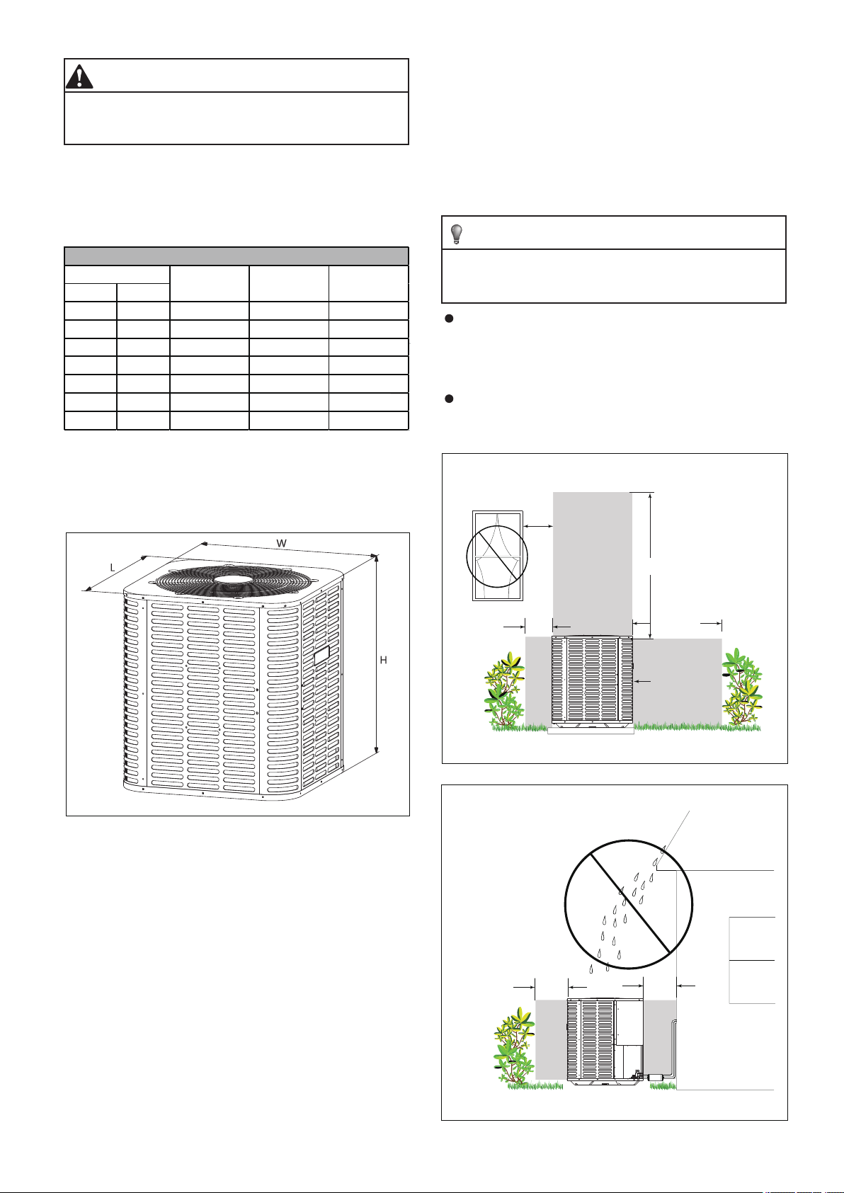
Unit Dimensions
Failure to follow this warning could result in property damage,
severe personal injury or death. Grounding is essential before
connecting electrical supply.
Position unit where water, snow or ice from roof or overhang cannot fall
directly on unit.
Position the outdoor unit a minimum of 12’’ from any wall or surrounding
shrubbery to ensure adequate airflow.
See Figure 2 and Figure 3.
2. Unit location considerations
2.1 Unit dimensions
Model
AC HP
18 24-15/16 21-7/8 21-7/8
/
24 18/24 24-15/16 23-5/8 23-5/8
30 30 24-15/16 28 28
36 36 24-15/16 29-1/8 29-1/8
4242 33-3/16 28 28
48 48 33-3/16 28 28
60 60 33-3/16 29-1/8 29-1/8
Table 1
The unit’s weight value is on the cardboard box.
When mounting the outdoor unit on a roof, be sure the roof will support
the unit’s weight. Properly selected isolation is recommended to prevent
sound or vibration transmission to the building structure.
H(Inches) W(Inches) L(Inches)
Cold climate considerations (heat pump only)
Precautions must be taken for units being installed in areas where
snow accumulation and prolonged below-freezing temperatures
occur.
Units should be elevated 3-12 inches above the pad or rooftop,
depending on local weather. This additional height will allow
drainage of snow and ice melted during defrost cycle prior to its
refreezing. Ensure that drain holes in unit base pan are not
obstructed, preventing drainage of defrost water (Figure 4).
If possible, avoid locations that are likely to accumulate snow
drifts. If not possible, a snow drift barrier should be installed
around the unit to prevent a build-up of snow on the sides of the
unit.
Avoid Install
Near Bedrooms
Min. 60” Unrestricted
Figure 1
2.2 Location restrictions
Ensure the top discharge area is unrestricted for at least 60 inches above
the unit.
Do not locate outdoor unit near bedrooms since normal operational
sounds may be objectionable.
Position unit to allow adequate space for unobstructed airflow, wiring,
refrigerant lines, and serviceability.
Maintain a distance of 24 inches between units.
Min. 12’’ to
Shrubbery
Figure 2
Min. 12” to
Shrubbery
Min. 24’’
Unrestricted
Access Panel
Min. 12” to
Wall
24 inches clearance must be provided in front of the control box (access
panels) and any other side requiring service.
2
Figure 3
Page 5
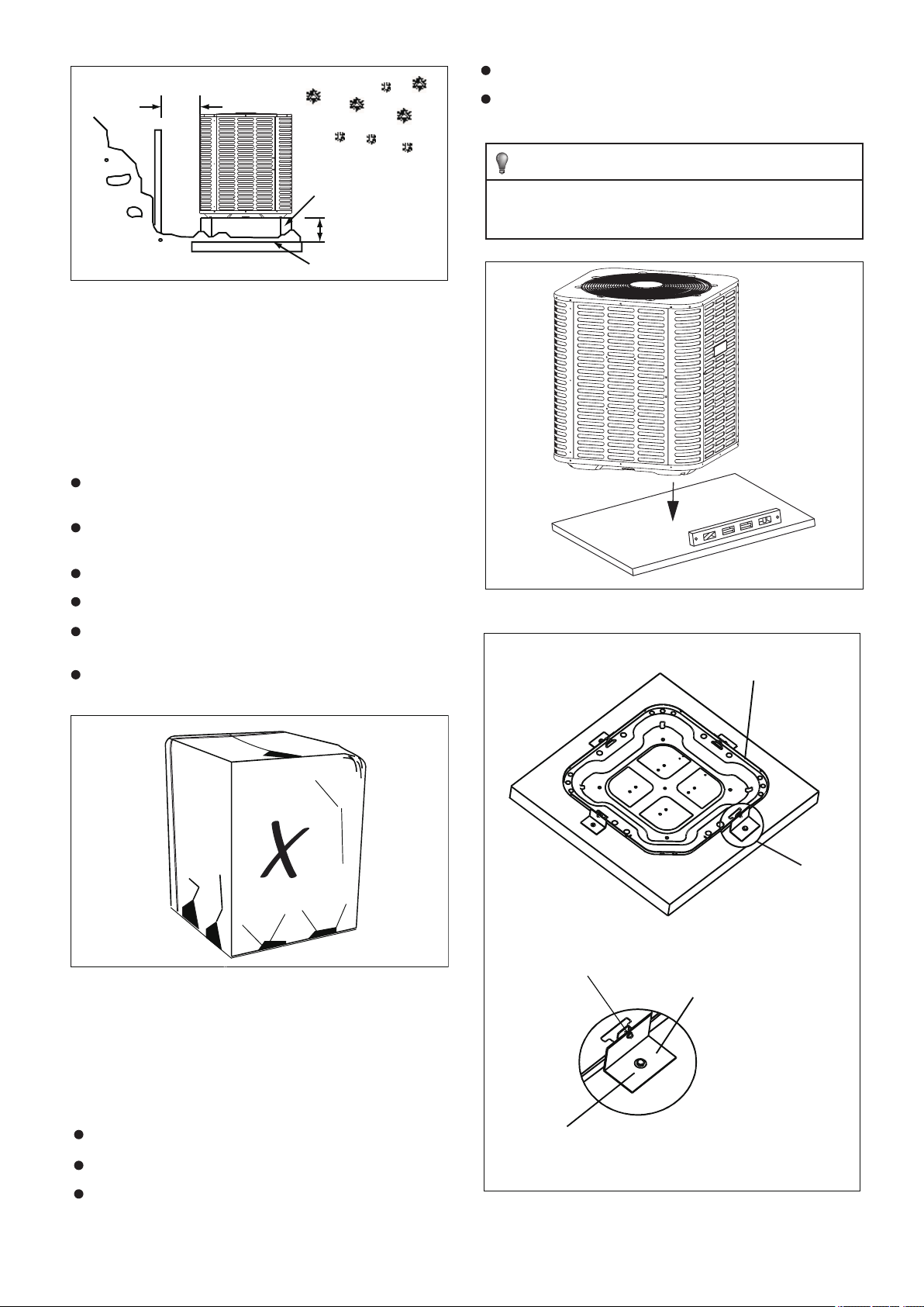
The pad must be high enough above grade to allow for drainage.
Min. 12"
Snow
barrier
Snow legs
3- 12" Elevation
pad
Figure 4
3. Unit preparation
3.1 Pre-installation
STEP 1 - Check for damage and report promptly to the carrier any
damage found to the unit (Figure 5).
STEP 2 - Instruments must be designed to install/serve R410A
equipmens.
Gauge sets, hoses, refrigerant containers and recovery system
must be designed to handle the POE type oils.
Manifold sets should be 800 PSIG high side and 250 PSIG low
side.
The pad location must comply with National, State and Local codes.
These instructions are intended to provide a method to tie-down
system to concrete slab as a securing procedure for high wind
areas. Check Local Codes for tie-down methods and protocols.
All hoses must have a 700 PSIG service pressure rating.
Leak detectors should be disigned to detect R410A.
Recovery equipments (including refrigerant recovery containers
) must be specifically designed to handle R410A.
Do not use an R22 TXV.
Figure
5
4. Setting up the unit
Figure
6
#7 X 3/8” Self Tapping Screws
(Don’t Exceed 3/8” long)
Detail A
The dimension
see Unit Dimensions.
See Detail A
Brackets:
2" width, 1/16" thickness,
height as required.
Available from distributor
or in market place.
4.1 Pad installation
When installing the unit on a support pad, such as a concrete slab,
consider the following:
The pad must be at least 1-2” larger than the unit on all sides.
The pad must be separate from any structure.
The pad must be level.
1/4” Χ 1-1/2” Hex Washer Head Concrete Screws
(3/16” Pilot Hole Needed. Pilot Hole Should Be 1/4” Deeper
Than The Fastener Embedment)
Figure
7
3
Page 6
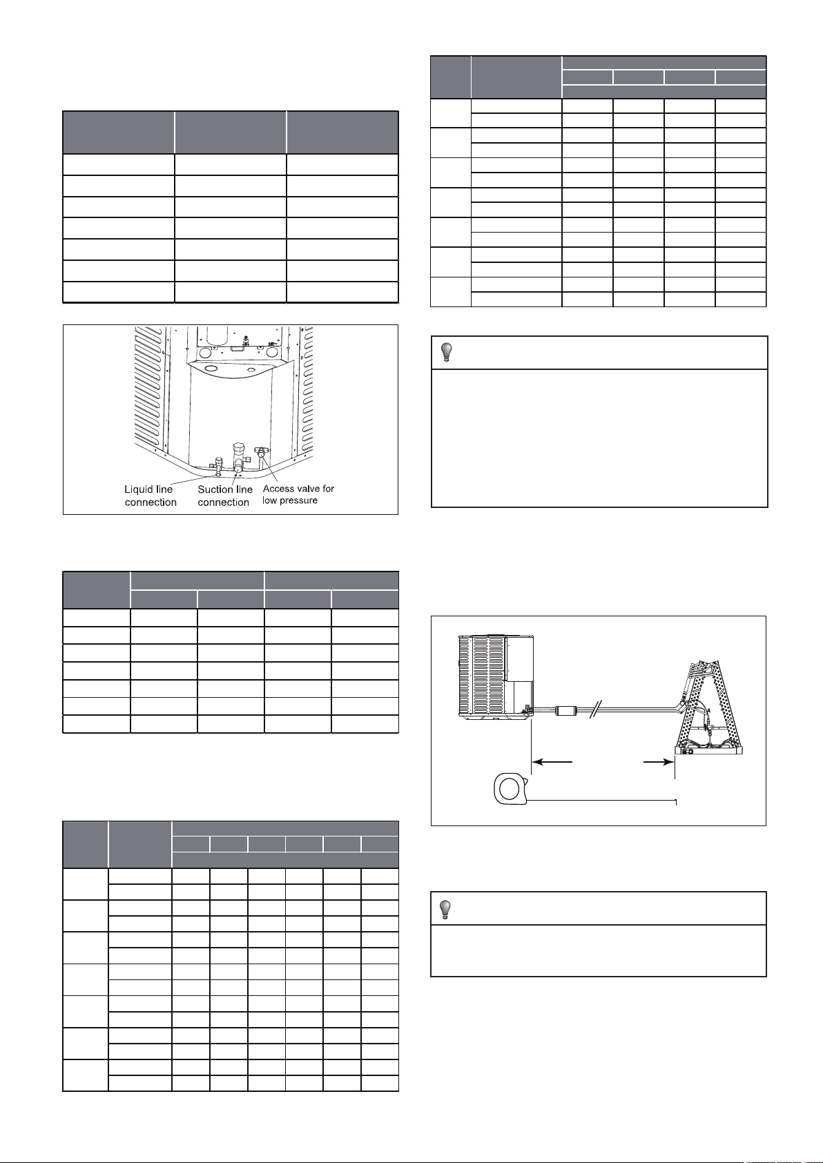
5. Refrigerant line considerations
optional standard optional standard
Suction line
Liquid line
25 50 75 100 125 150
3/8 25 50 56 44 32 20
Total equivalent length(Feet)
Maximum vertical length(Feet)
25 50 100 150
1-1/8 1.00 0.99 0.98 0.97
Coefficient
Total suction line length(Feet)
5.1 Service valve connection sizes
Model
18 3/4 3/8
24 3/4 3/8
30 3/4 3/8
36 3/4 3/8
42 3/4 3/8
48 7/8 3/8
60 7/8 3/8
Table 2
Suction line
connection
Liquid line
connection
Model
18
24
30
36
42
48
60
Table 5 Suction line length/size VS capcaity multiplier
Using suction line larger than shown in chart will result in poor oil
return and is not recommended.
For example: the system capacity published in AHRI is 17800
Btu/h. This data is based on the AHRI test condition and 25 feet
line set with standard suction tube size (3/4" tube). If you need to
add the line set more than 25 feet or use the optional suction
tube size, you need to recalculate the capacity with the
coefficient in the table. For 50 feet line and 5/8" suction tube, the
capacity will be 17800*0.97=17266 Btu/h.
Suction line
(Inches)
5/8 1.00 0.97 0.94 0.90
3/4 1.00 0.98 0.95 0.92
5/8 1.00 0.97 0.94 0.90
3/4 1.00 0.98 0.95 0.92
5/8 1.00 0.97 0.94 0.90
3/4 1.00 0.98 0.96 0.93
5/8 1.00 0.97 0.94 0.90
3/4 1.00 0.99 0.97 0.96
5/8 1.00 0.98 0.95 0.91
3/4 1.00 0.98 0.97 0.96
3/4 1.00 0.98 0.95 0.92
7/8 1.00 0.98 0.97 0.96
7/8 0.99 0.98 0.94 0.90
Figure
8
5.2 Refrigerant line sizes
Model
18 5/8 3/4 5/16 3/8
24 5/8 3/4 5/16 3/8
30 5/8 3/4 5/16 3/8
36 5/8 3/4 5/16 3/8
42 5/8 3/4 5/16 3/8
48 3/4 7/8 1/2 3/8
60 7/8 1-1/8 1/2 3/8
Table 3
5.3 Refrigerant piping limits and required refrigerant
line length
18
24
30
36
42
48
60
Liquid line
(Inches)
5/16 25 50 60 58 40 30
3/8 25 50 60 60 40 30
5/16 25 36 29 23 16 9
3/8 25 50 60 60 40 30
5/16 25 49 38 27 17 6
3/8 25 50 60 60 40 30
5/16 25 50 37 22 7 N/A
3/8 25 50 60 60 40 30
5/16 25 23 4 N/A N/A N/A
3/8 25 50 43 36 30 24
1/2 25 50 56 55 40 30
3/8 25 46 38 30 22 15
1/2 25 50 60 60 40 30
Model
Determine required line length and lift. You will need this later in Section
14.
Total Line Length = __________ Feet.
Total vertical Change(Lift) = __________ Feet.
Line Length
Figure 9
5.4 Refrigerant line insulation
The suction line must always be insulated. DO NOT allow the
Liquid Line and Suction Line to come in direct (metal to metal)
contact.
Table 4
4
Page 7

Figure 10
5.5 Reuse existing refrigerant lines
CAUTION:
If using existing refrigerant lines make certain that all joints are
brazed, not soldered.
For retrofit applications, where the existing refrigerant lines will be used,
the following precautions should be taken:
Ensure that the refrigerant lines are the correct size. Refer to
Section 5.1 listed and Table 3.
Ensure that the refrigerant lines are free of leaks, acid, and oil.
The manufacturer recommends installing only approved matched
indoor and outdoor systems. All of the manufacturer’s split
systems are AHRI certified. Some of the benefits of installing
approved matched indoor and outdoor split systems are maximum
efficiency, optimum performance and the best overall system
reliability.
Figure 11
6. Refrigerant line routing
6.1 Precautions
Take precautions to prevent noise within the building structure
due to vibration transmission from the refrigerant lines. For
example:
When the refrigerant lines have to be fastened to floor joists or
other framing in a structure, use isolation type hangers.
Isolation hangers should also be used when refrigerant lines are
run in stud spaces or enclosed ceilings.
Where the refrigerant lines run through a wall or sill, they should
be insulated and isolated.
Isolate the lines from all ductwork.
Minimize the number of 90º turns.
Use PVC piping as a conduit for all underground installations as
shown in Figure 15. Buried lines should be keep as short as
possible.
The lines should not obstruct service access to the coil, air
handling system or filter.
Care must also be taken to isolate the refrigerant lines to
minimize noise transmission from the equipment to the
structure.
Comply with National, State, and Local Codes when isolating line
sets from joists, rafters, walls or other structural elements.
Figure 12
Side Vi ew
8 Feet Maximum
8 Feet Maximum
Secure Suction li n e from jois ts us ing isolators every 8 feet. Secure
Liquid Line directly to Suc tion line using tape, wire, or other
approp riate m ethod ever y 8 feet.
Isolation From Joist/Rafter
5
Joist/Raft er
Isolator
Line Set
Page 8

8 Feet Maximum
Wall
Isolator
Figure 13
Wall
Side View
Sealant
Insulation
8 Feet Maximum
Secure Suc tion Line using isolators ever y 8 feet.
Secure Liqu id Line directly t o Suction Line using
tape, wir e, or other approp ri ate m ethod every 8 feet.
Isolation In Wall Spaces
Sucti o n Li ne
Line Set
Ductwork
Is
olator
Isolation Through Wall
Figure 14
Line Set
DO NOT han g line s ets from d uctwork
Figure 15
6
Page 9

7. Refrigerant line brazing
7.1 Braze the refrigerant lines
1.
Remove caps or plugs. Use a deburing tool to debur the pipe ends.
Clean both internal and external surfaces of the tubing using an emery
cloth.
Figure 16
Wrap a wet rag around the valve body to avoid heat damage and
4.
continue the dry nitrogen purge (Figure 19).
Braze the refrigerant lines to the service valves.
Check liquid line filter drier’s directional flow arrow to confirm correct
direction of refrigeration flow (away from outdoor unit and toward
evaporator coil) as illustrated. Brazing the filter drier to the Liquid
Line.
Continue the dry nitrogen purge. Do not remove the wet rag until all
brazing is completed.
Remove the wet rag before stopping the dry nitrogen purge.
Field supplied
and installed
2. Remove the pressure tap cap from both service valves.
Figure 17
3. Purge the refrigerant lines and indoor coil with dry nitrogen.
3-4" from valve
Figure 19
5. Replace the pressure tap caps after the service valves have cooled.
Note: Do not over tighen (between 40 and 60 inch-lbs. maximum).
This pipe
must have
a thimble
Figure 18
Figure 20
7
Page 10

8. Refrigerant line leak check
150 PSI
G
8.1 Check for leaks
1.
Pressurize the refrigerant lines and evaporator coil to 150 PSIG using
dry nitrogen.
Figure 21
Check for leaks by using a soapy solution or bubbles at each brazed
2.
location.
Evacuate until the micron gauge reads no higher than 350 microns,
1.
then close off the valve to the vacuum pump.
0350
Microns
ON
OFF
Figure 23
Observe the micron gauge. Evacuation is complete if the micron
2.
gauge does not rise above 500 microns in one (1) minute.
Once evacuation is complete blank off the vacuum pump and micron
gauge, and close the valves on the manifold gauge set.
1 MIN.
Figure 22
Remove nitrogren pressure and repair any leaks before continuing.
9. Evacuation
9.1 Evacuate the refrigerant lines and indoor coil
Do not open the service valves until the refrigerant lines and
indoor coil leak check and evacuation are complete.
Figure 24
10. Service valves
10.1 Open the service valves
WARNING:
Extreme caution should be exercised when opening the Liquid
Line Service Valve. Turn counterclock wise until the valve stem
just touches the rolled edge. No torque is required. Failure to
follow this warning will result in abrupt release of system charge
and may result in personal injury and /or property damage.
Leak check and evacuation must be completed before opening the
service valves.
Remove service valve cap (Figure 25).
1.
Fully insert hex wrench into the stem and back out counterclockwise
2.
until valve stem just touches the rolled edge.
Replace the valve stem cap to prevent leaks. Tighten finger tight
3.
plus an additional 1/6 turn.
8
Page 11

Cap
5/16” Hex Wrench
for Su cti on Ser vi ce Val ve
11. Electrical - low voltage
11.1 Low Voltage Maximum Wire Length
Unit S ide
of Serv ice
Valve
3/16” Hex Wrench
for L iqu id Ser vice Val ve
Roll ed Edg e to
Capti vate Stem
Serv ic e Port
Figure 25
11.2 Low voltage hook-up diagrams
Air Handler Hook-up Diagram
Hex Headed
Valve System
Table 6 defines the maximum total length of low voltage wiring from
the outdoor unit to the indoor unit and to the thermostat.
24 Volts - Wire size Max. wire length
18 AWG 150 Ft.
16 AWG 225 Ft.
14 AWG 300 Ft.
Table 6
Low Voltage connection
Figure 26
must be made inside the
W
B
C
R
Y
G
FOR ONE STAGE
HEAT THERMOSTAT
RED
GREEN
WHITE
BLACK
C
RG Y
w1 w2
BLACK
C
INDOOR UNIT OUTDOOR UNIT
Control Wiring for A/C Systems
Figure 27
Notes: “-----”The electric auxiliary heat connection(optional).
W:Electric auxiliary heat signal.
W1 :The first Electric auxiliary heat signal.
W2 :The second Electric auxiliary heat signal.
YELLOW
outdoor unit case.
W2
W1
B
C
R
Y
G
FOR TWO STAGE
HEAT THERMOSTAT
RED
GREEN
BLACK
w1
R
C
G
INDOOR UNIT
WHITE
w2
Panel
Access
BLACK
YELLOW
C
Y
OUTDOOR UNIT
9
Page 12

Support 2H thermostat
Support 3H thermostat
W
B
C
R
Y
G
*
THERMOSTAT
Figure 28
Notes:
“-----”The electric auxiliary heat connection(option).
W:Electric auxiliary heat signal.
W1 :The first Electric auxiliary heat signal.
W2 :The second Electric auxiliary heat signal.
D signal is connect to the Electric auxiliary heat or The first Electric auxiliary heat.
“*”:Outdoor unit signal. Only for single-stage compressor systems.
RED
GREEN
BLACK
R
C
G
INDOOR UNIT
WHITE
w1
w2
12. Electrical - high voltage
YELLOW
BLACK
R
C B
OUTDOOR UNIT
W2
W1
B
C
R
Y
G
BLUE
PURPLE
Y
D
THERMOSTAT
Control Wiring for H/P Systems
12.2 High voltage disconnect switch
BLACK
GREEN
RED
R
C
G
INDOOR UNIT
WHITE
w1
w2
*
BLACK
R
C B
OUTDOOR UNIT
YELLOW
Y
BLUE
PURPLE
D
12.1 High voltage power supply
WARNING: LIVE ELECTRICAL COMPONENTS!
During installation, testing, servicing, and trouble shooting of this
product,
it may be necessary to work with live electrical
Failure to follow all electrical safety precautions when exposed to
live electrical components could result in death or serious injury.
The high voltage power supply must agree with the equipment
nameplate.
Power wiring must comply with National, State and Local Codes.
Follow instructions on unit wiring diagram located on the inside of the
access panel.
n
a
m
e
p
l
a
e
t
components.
Install a separate disconnect switch at the outdoor unit.
Field provided flexible electrical conduit must be used for high voltage
wiring.
Figure 30
12.3 High voltage ground
Ground the outdoor unit per National, State and Local Code
requirements.
Figure 29
10
Page 13

0.4 oz/ft 0.6 oz/ft 1.2 oz/ft
The data on
nameplate
Wait one (1) hour before starting the unit if compressor crankcase
O
CO
O
4.
heater is used and the outdoor ambient temperature is below 70 ºF.
60 MIN.
Figure 34
Set system thermostat to ON.5.
Figure 31
13. Start up
13.1 System start up
Ensure Sections 7, 8, 9, 10, 11 and 12 have been completed.
1.
Set System Thermostat to OFF.
2.
OFF
D
N
Figure 32
Turn on disconnect to apply power to the indoor and outdoor units.3.
CANCEL
TUE
Inside Set To
Following
EM HEAT
FF
L
D
NE CANCEL
Schedule
Figure 35
14. System charge adjustment
14.1 Charging: Weigh-In Method
Weigh-In method can be used for the initial installation, or anytime a
system charge is being replaced. Weigh-In Method can also be used
when power is not available to the equipment site or operating
conditions (indoor/outdoor temperatures) are not in range to verify
liquid line pressure
with the
Model Factory Charge
charging method.
Charge multiplier for
liquid line length
Figure 33
ON
OFF
All models
5/16'' 3/8'' 1/2''
Table 7
The factory charge in the outdoor unit is sufficient for 15 feet of
standard size interconnecting liquid line.
New Installations — Calculating additional charge for lineset
greater than 15 feet.
1. Total Line Length (ft)
2. Standard Line set (ft)
3. (a) minus (b)
4. Refrigerant Multiplier
5. Refrigerant Adder (c*d)
*If lineset is less than 15 feet, (e) = 0
= (a)
= 15 (b)
= (c)
= (d)
= (e*)
11
Page 14

Sealed-System Repairs — Calculating total system charge.
1. Total Line Length (ft)
2. Standard Line set (ft)
3. (a) minus (b)
4. Refrigerant Multiplier
5. Refrigerant Adder (c*d)
6. Factory Charge (nameplate)
7. Total System Charge (e+f)
*If line set is less than 15 feet, (e) = 0
= (a)
= 15 (b)
= (c)
= (d)
= (e*)
= (f)
= _
Ensure Sections 7, 8, 9, 10,11,12 and 13 have been completed.
2.
Stabilize the system by operating for a minimum of 20 minutes. 3.
At startup, or whenever charge is removed or added, the system
must be operated for a minimum of 20 minutes to stabilize before
accurate measurements can be made.
The only mode approved for validating system charge is while in
Cooling Mode. Outdoor Temperature must be between 55°F and
115°F with Indoor Temperature kept between 70°F and 80°F.
14.2 Liquid line pressure charging and refrigerant
adjustment in cooling (above 55°F outdoor temp.)
Check the outdoor ambient temperatures.
1.
Liquid line pressure (in cooling mode) is the only recommended
method of charging above 55ºF outdoor ambient temperatures.
For outdoor ambient temperatures below 55ºF , use weigh-in charge
method.
Note:It is important to return in the spring or summer to accurately
charge the system in the cooling mode when outdoor ambient
temperature is above 55ºF.
Outdoor
Temperature
Above 55ºF
115ºF
Outdoor
Temperature
Below 55ºF
20 MIN.
Figure 38
Calculate liquid line pressure (According to Refrigerant Charging
4.
Chart)
Measured Suction Line Pressure = ________PSIG
Outdoor Ambient Temperature = _______ ºF
Calculate Liquid Line Pressure = ________PSIG
55ºF
Outdoor Temp.1
Figure 36
For best results the indoor temperature should be kept between 70ºF
to 80ºF.
55ºF
Outdoor Temp. 2
80ºF
70ºF
Indoor Temp.
Figure 37
Figure 39
12
Page 15

REFRIGERANT CHARGING CHART FOR AC SYSTEM
105
14 SEER R410A AC Charge Chart 2 TON
Outdoor Ambient Temperature(℉)
Liquid Pressure at Small Service Valve(psig)
105
14 SEER R410A AC Charge Chart 1.5 TON
Outdoor Ambient Temperature(℉)
Liquid Pressure at Small Service Valve(psig)
105
14 SEER R410A AC Charge Chart 2.5 TON
Outdoor Ambient Temperature(℉)
Liquid Pressure at Small Service Valve(psig)
Liquid Pressure at Small Service Valve(psig)
Cooling
Mode
Suction Pressure at
Large Service Valve(psig)
Cooling
Mode
Suction Pressure at
Large Service Valve(psig)
165
161
157
153
149
145
141
137
133
129
125
121
117
113
109
165
161
157
153
149
145
141
137
133
129
125
121
117
113
109
55 60 65 70 75 80 85 90 95 100 105 110 115
253 274 296 317 336 354 373 400 428 455 482
251 272 294 315 334 352 371 398 426 453 480
249 270 292 313 332 350 369 396 424 451 478
231 247 268 290 311 330 348 367 394 422 449 476
229 245 266 288 309 328 346 365 392 420 447 474
227 243 264 286 307 326 344 363 390 418 445 472
208 225 241 262 284 305 324 342 361 388 416 443 470
206 223 239 260 282 303 322 340 359 386 414 441 468
204 221 237 258 280 301 320 338 357 384 412 439 466
202 219 235 256 278 299 318 336 355 382 410 437 464
200 217 233 254 276 297 316 334 353 380 408 435 462
198 215 231 252 274 295 314 332 351 378 406 433 460
196 213 229 250 272 293 312 330 349 376 404 431 458
194 211 227 248 270 291 310 328 347 374 402 429 456
192 209 225 246 268 289 308 326 345 372 400 427 454
190 207 223 244 266 287 306 324 343 370 398 425 452
55 60 65 70 75 80 85 90 95 100 105 110 115
256
275 295 31
254 273 293 312 334 355 377 403 429 455 481
252 271 291 310 332 353 375 401 427 453 479
233 250 269 289 308 330 351 373 399 425 451 477
231 248 267 287 306 328 349 371 397 423 449 475
229 246 265 285 304 326 347 369 395 421 447 473
210 227 244 263 283 302 324 345 367 393 419 445 471
208 225 242 261 281 300 322 343 365 391 417 443 469
206 223 240 259 279 298 320 341 363 389 415 441 467
204 221 238 257 277 296 318 339 361 387 413 439 465
202 219 236 255 275 294 316 337 359 385 411 437 463
200 217 234 253 273 292 314 335 357 383 409 435 461
198 215 232 251 271 290 312 333 355 381 407 433 459
196 213 230 249 269 288 310 331 353 379 405 431 457
194 211 228 247 267 286 308 329 351 377 403 429 455
192 209 226 245 265 284 306 327 349 375 401 427 453
4 336 357 379 405 431 457 483
Cooling
Mode
165
161
157
153
149
145
141
137
133
129
125
Suction Pressure at
121
Large Service Valve(psig)
117
113
109
Cooling
Mode
165
161
157
153
149
145
141
137
133
129
125
121
Suction Pressure at
117
Large Service Valve(psig)
113
109
105
55 60 65 70 75 80 85 90 95 100 105 110 115
250 272 293 315 334 353 372 398 425 451 477
248 270 291 313 332 351 370 396 423 449 475
246 268 289 311 330 349 368 394 421 447 473
227 244 266 287 309 328 347 366 392 419 445 471
225 242 264 285 307 326 345 364 390 417 443 469
223 240 262 283 305 324 343 362 388 415 441 467
204 221 238 260 281 303 322 341 360 386 413 439 465
202 219 236 258 279 301 320 339 358 384 411 437 463
200 217 234 256 277 299 318 337 356 382 409 435 461
198 215 232 254 275 297 316 335 354 380 407 433 459
196 213 230 252 273 295 314 333 352 378 405 431 457
194 211 228 250 271 293 312 331 350 376 403 429 455
192 209 226 248 269 291 310 329 348 374 401 427 453
190 207 224 246 267 289 308 327 346 372 399 425 451
188 205 222 244 265 287 306 325 344 370 397 423 449
186 203 220 242 263 285 304 323 342 368 395 421 447
14 SEER R410A AC Charge Chart 3 TON
55 60 65 70 75 80 85 90 95 100 105 110 115
257 277 296 316 339 361 384 410 436 462 488
255 275 294 314 337 359 382 408 434 460 486
253 273 292 312 335 357 380 406 432 458 484
235 251 271 290 310 333 355 378 404 430 456 482
233 249 269 288 308 331 353 376 402 428 454 480
231 247 267 286 306 329 351 374 400 426 452 478
212 229 245 265 284 304 327 349 372 398 424 450 476
210 227 243 263 282 302 325 347 370 396 422 448 474
208 225 241 261 280 300 323 345 368 394 420 446 472
206 223 239 259 278 298 321 343 366 392 418 444 470
204 221 237 257 276 296 319 341 364 390 416 442 468
202 219 235 255 274 294 317 339 362 388 414 440 466
200 217 233 253 272 292 315 337 360 386 412 438 464
198 215 231 251 270 290 313 335 358 384 410 436 462
196 213 229 249 268 288 311 333 356 382 408 434 460
194 211 227 247 266 286 309 331 354 380 406 432 458
Outdoor Ambient Temperature( )
℉
13
Page 16

Cooling
Liquid Pressure at Small Service Valve(psig)
105
14 SEER R410A AC Charge Chart 4 TON
Outdoor Ambient Temperature(℉)
Liquid Pressure at Small Service Valve(psig)
105
14 SEER R410A AC Charge Chart 5 TON
Outdoor Ambient Temperature(℉)
Liquid Pressure at Small Service Valve(psig)
Mode
165
161
157
153
149
145
141
137
133
129
125
121
Suction Pressure at
117
Large Service Valve(psig)
113
109
105
Cooling
Mode
165
161
157
153
149
145
141
137
133
129
125
Suction Pressure at
121
Large Service Valve(psig)
117
113
109
14 SEER R410A AC Charge Chart 3.5 TON
55 60 65 70 75 80 85 90 95 100 105 110 115
250 269 288 307 329 351 373 400 426 453 479
248 267 286 305 327 349 371 398 424 451 477
246 265 284 303 325 347 369 396 422 449 475
227 244 263 282 301 323 345 367 394 420 447 473
225 242 261 280 299 321 343 365 392 418 445 471
223 240 259 278 297 319 341 363 390 416 443 469
204 221 238 257 276 295 317 339 361 388 414 441 467
202 219 236 255 274 293 315 337 359 386 412 439 465
200 217 234 253 272 291 313 335 357 384 410 437 463
198 215 232 251 270 289 311 333 355 382 408 435 461
196 213 230 249 268 287 309 331 353 380 406 433 459
194 211 228 247 266 285 307 329 351 378 404 431 457
192 209 226 245 264 283 305 327 349 376 402 429 455
190 207 224 243 262 281 303 325 347 374 400 427 453
188 205 222 241 260 279 301 323 345 372 398 425 451
186 203 220 239 258 277 299 321 343 370 396 423 449
55 60 65 70 75 80 85 90 95 100 105 110 115
258 277 297 316 339 361 384 411 4 38 465 492
256 275 295 314 337 359 382 409 4 36 463 490
254 273 293 312 335 357 380 407 4 34 461 488
234 252 271 291 310 333 355 378 405 432 459 486
232 250 269 289 308 331 353 376 403 430 457 484
230 248 267 287 306 329 351 374 401 428 455 482
210 228 246 265 285 304 327 349 372 399 426 453 480
208 226 244 263 283 302 325 347 370 397 424 451 478
206 224 242 261 281 300 323 345 368 395 422 449 476
204 222 240 259 279 298 321 343 366 393 420 447 474
202 220 238 257 277 296 319 341 364 391 418 445 472
200 218 236 255 275 294 317 339 362 389 416 443 470
198 216 234 253 273 292 315 337 360 387 414 441 468
196 214 232 251 271 290 313 335 358 385 412 439 466
194 212 230 249 269 288 311 333 356 383 410 437 464
192 210 228 247 267 286 30
Outdoor Ambient Temperature(℉)
9 331 35
4 381 408 435 462
Cooling
Mode
Suction Pressure at
Large Service Valve(psig)
165
161
157
153
149
145
141
137
133
129
125
121
117
113
109
55 60 65 70 75 80 85 90 95 100 105 110 115
265 285 305 325 348 372 395 423 450 478 505
263 283 303 323 346 370 393 421 448 476 503
261 281 301 321 344 368 391 419 446 474 501
242 259 279 299 319 342 366 389 417 444 472 499
240 257 277 297 317 340 364 387 415 442 470 497
238 255 275 295 315 338 362 385 413 440 468 495
219 236 253 273 293 313 336 360 383 411 438 466 493
217 234 251 271 291 311 334 358 381 409 436 464 491
215 232 249 269 289 309 332 356 379 407 434 462 489
213 230 247 267 287 307 330 354 377 405 432 460 487
211 228 245 265 285 305 328 352 375 403 430 458 485
209 226 243 263 283 303 326 350 373 401 428 456 483
207 224 241 261 281 301 324 348 371 399 426 454 481
205 222 239 259 279 299 322 346 369 397 424 452 479
203 220 237 257 277 297 320 344 367 395 422 450 477
201 218 235 255 275 295 318 342 365 39
REFRIGERANT CHARGING CHART FOR HP SYSTEM
Cooling
Mode
Suction Pressure at
Large Service Valve(psig)
55 60 65 70 75 80 85 90 95 100 105 110 115
165
161
157
153
149
145
141
137
133
129
125
121
117
113
109
105
221 240 259 278 297 317 337 358 384 410 435 461
219 238 257 276 295 315 335 356 382 408 433 459
217 236 255 274 293 313 333 354 380 406 431 457
196 215 234 253 272 291 311 331 352 378 404 429 455
195 213 232 251 269 288 309 328 350 376 402 427 453
193 211 230 249 267 286 306 326 347 373 399 425 451
191 209 228 247 265 284 304 323 344 370 397 423 449
190 209 227 245 264 282 302 320 341 368 394 421
190 208 226 244 262 280 300 320 341 367 393 419 445
188 206 224 242 260 278 298 318 339 365 391 417 443
186 204 222 240 258 276 296 316 337 363 389 415 441
184 202 220 238 256 274 294 314 335 361 387 413 439
182 200 218 236 254 272 292 312 333 359 385 411 437
14SEER R410A HP Charge Chart 1.5 TON(Cooling mode)
Liquid Pressure at Small Service Valve(psig)
246 265 284 303 323 343 364 390 416 441 467
244 263 282 301 321 341 362 388 414 439 465
242 261 280 299 319 339 360 386 412 437 463
3 420 448 475
Outdoor Ambient Temperature(℉)
447
14
Page 17

Cooling
Mode
Suction Pressure at
Large Service Valve(psig)
14SEER R410A HP Charge Chart 2 TON(Cooling mode)
55 60 65 70 75 80 85 90 95 100 105 110 115
165
161
157
153
149
145
141
204 224 243 262 282 301 323 346 369 395 422 449 474
137
203 222 241 260 279 298 320 344 367 393 420 447 472
133
201 220 239 258 277 296 318 342 365 391 418 445 470
129
199 218 237 256 275 294 316 340 363 389 416 443 468
125
197 216 235 254 273 292 314 338 361 387 414 441 466
121
195 214 233 252 271 290 312 336 359 385 412 439 464
117
193 212 231 250 269 288 310 334 357 383 410 437 462
113
191 210 229 248 267 286 308 332 355 381 408 435 460
109
189 208 227 246 265 284 306 330 353 379 406 433 458
105
187 206 225 244 263 282 304 328 351 377 404 431 456
255 274 294 313 335 358 381 407 434 461 486
253 272 292 311 333 356 379 405 432 459 484
251 270 290 309 331 354 377 403 430 457 482
230 249 268 288 307 329 352 375 401 428 455 480
228 247 266 286 305 327 350 373 399 426 453 478
226 245 264 284 303 325 348 371 397 424 451 476
Outdoor Ambient Temperature(℉)
Liquid Pressure at Small Service Valve(psig)
Cooling
Mode
Suction Pressure at
Large Service Valve(psig)
Cooling
Mode
Suction Pressure at
Large Service Valve(psig)
14SEER R410A HP Charge Chart 2.5 TON(Cooling mode)
55 60 65 70 75 80 85 90 95 100 105 110 115
165
161
157
153
149
145
141
208 225 241 257 276 293 315 336 358 378 402 423 449
137
206 223 239 255 274 291 313 334 356 376 400 421 447
133
204 221 237 253 272 289 311 332 354 374 398 419 445
129
202 219 235 251 270 287 309 330 352 372 396 417 443
125
199 215 232 249 267 285 307 328 350 370 394 415 441
121
195 213 230 247 267 285 306 327 348 368 392 413 439
117
193 211 228 245 265 283 304 325 346 366 390 411 437
113
191 209 226 243 263 281 302 323 344 364 388 409 435
109
189 207 224 241 261 279 300 321 342 362 386 407 433
105
187 205 222 239 259 277 298 319 340 360 384 405 431
253 269 288 305 327 348 370 390 414 435 461
251 267 286 303 325 346 368 388 412 433 459
249 265 284 301 323 344 366 386 410 431 457
231 247 263 282 299 321 342 364 384 408 429 455
229 245 261 280 297 319 340 362 382 406 427 453
227 243 259 278 295 317 338 360 380 404 425 451
14SEER R410A HP Charge Chart 3 TON(Cooling mode)
55 60 65 70 75 80 85 90 95 100 105 110 115
165
161
157
153
149
145
212 230 248 266 284 302 323 345 366 388 413 442 470
141
210 228 246 264 282 300 321 342 363 385 411 439 468
137
208 226 244 262 280 298 319 339 360 382 408 437 466
133
206 224 242 260 278 296 316 337 357 379 406 435 464
129
204 222 240 258 276 294 314 335 355 377 404 433 462
125
202
121
200 218 236 254 272 290 310 331 351 373 400 429 458
117
198 216 234 252 270 288 308 329 349 371 398 427 456
113
196 214 232 250 268 286 306 327 347 369 396 425 454
109
194 212 230 248 266 284 304 325 345 367 394 423 452
105
260 278 296 314 336 359 381 402 427 454 482
258 276 294 312 334 357 379 400 425 452 480
256 274 292 310 332 355 377 398 423 450 478
236 254 272 290 308 330 352 374 395 420 448 476
234 252 270 288 306 328 350 372 393 418 446 474
232 250 268 286 304 326 347 369 390 416 444 472
220 238 256 274 292 312 333 353 375 402 431 460
Outdoor Ambient Temperature(℉)
Liquid Pressure at Small Service Valve(psig)
Outdoor Ambient Temperature(℉)
Liquid Pressure at Small Service Valve(psig)
Cooling
Mode
Suction Pressure at
Large Service Valve(psig)
14SEER R410A HP Charge Chart 3.5 TON(Cooling mode)
55 60 65 70 75 80 85 90 95 100 105 110 115
165
161
157
153
149
145
208 225 242 259 276 293 315 336 358 382 405 429 452
141
206 223 240 257 274 291 313 334 356 380 403 427 450
137
204 221 238 255 272 289 311 332 354 378 401 425 448
133
202 219 236 253 270 287 309 330 352 376 399 423 446
129
200 217 234 251 268 285 307 328 350 374 397 421 444
125
198 215 232 249 266 283 305 326 348 372 395 419 442
121
196 213 230 247 264 281 303 324 346 370 393 417 440
117
194 211 228 245 262 279 301 322 344 368 391 415 438
113
192 209 226 243 260 277 299 320 342 366 389 413 436
109
190 207 224 241 258 275 297 318 340 364 387 411 434
105
254 271 288 305 327 348 370 394 417 441 464
252 269 286 303 325 346 368 392 415 439 462
250 267 284 301 323 344 366 390 413 437 460
231 248 265 282 299 321 342 364 388 411 435 458
229 246 263 280 297 319 340 362 386 409 433 456
227 244 261 278 295 317 338 360 384 407 431 454
Outdoor Ambient Temperature(℉)
Liquid Pressure at Small Service Valve(psig)
15
Page 18

Cooling
Mode
Suction Pressure at
Large Service Valve(psig)
14SEER R410A HP Charge Chart 4 TON(Cooling mode)
55 60 65 70 75 80 85 90 95 100 105 110 115
165
161
157
153
149
145
206 225 243 261 279 298 318 339 359 384 408 433 457
141
204 223 241 259 277 296 316 337 357 382 406 431 455
137
204 222 240 258 275 294 314 335 355 380 404 429 453
133
129
202 220 238 256 273 292 312 333 353 378 402 427 451
125
200 218 236 254 271 290 310 331 351 376 400 425 449
121
198 216 234 252 269 288 308 329 349 374 398 423 447
117
196 214 232 250 267 286 306 327 347 372 396 421 445
113
194 212 230 248 265 284 304 325 345 370 394 419 443
109
192 210 228 246 263 282 302 323 343 368 392 417 441
105
190 208 226 244 261 280 300 321 341 366 390 415 439
255 273 291 310 330 351 371 396 420 445 469
253 271 289 308 328 349 369 394 418 443 467
251 269 287 306 326 347 367 392 416 441 465
231 249 267 285 304 324 345 365 390 414 439 463
229 247 265 283 302 322 343 363 388 412 437 461
227 245 263 281 300 320 341 361 386 410 435 459
Outdoor Ambient Temperature(℉)
Liquid Pressure at Small Service Valve(psig)
Cooling
Mode
165
161
157
153
149
145
141
137
133
129
125
Suction Pressure at
121
Large Service Valve(psig)
117
113
109
105
Adjust refrigerant level to attain proper gage pressure.
5.
55 60 65 70 75 80 85 90 95 100 105 110 115
249 267 285 303 323 344 364 392 415 441 466
247 265 283 301 321 342 362 391 413 439 464
245 263 281 299 319 340 360 389 411 437 462
225 243 261 279 297 317 338 358 387 409 435 460
223 241 259 277 295 315 336 356 385 407 433 458
221 239 257 275 293 313 334 354 383 405 431 456
201 219 237 255 273 291 311 332 352 381 403 429 454
199 217 235 253 271 289 309 330 350 379 401 427 452
197 215 233 251 269 287 307 328 348 377 399 425 450
195 213 231 249 267 285 305 326 346 375 397 423 448
193 211 229 247 265 283 303 324 344 373 395 421 446
191 209 227 245 263 281 301 322 342 371 393 419 444
189 207 225 243 261 279 299 320 340 369 391 417 442
187 205 223 241 259 277 297 318 338 367 389 415 440
185 203 221 239 257 275 295 316 336 365 387 413 438
183 201 219 237 255 273 293 314 334 363 385 411 436
14SEER R410A HP Charge Chart 5 TON(Cooling mode)
Outdoor Ambient Temperature(℉)
Liquid Pressure at Small Service Valve(psig)
Add refrigerant if the design liquid line pressure is lower than the
chart value.
Connect gages to refrigerant bottle and unit as illustrated (Figure
40).
Purge all hoses.
Open bottle.
Stop adding refrigerant when liquid line pressure matches the
Refrigerant Charging Chart.
Stabilize the system.
6.
Wait 20 minutes for the system condition to stabilize between
adjustments.
When the liquid line pressure match the chart, the system is
properly charged.
Remove gages.
Replace service port caps to prevent leaks. Tighten finger tight plus
an additional 1/6 turn.
20 MIN.
Recover refrigerant if the design liquid line pressure is lower than
the chart value.
Figure 40
Figure 41
Record system Information for reference (Table 8).
7.
Record system pressures and temperatures after charging is
complete.
Description Value
Outdoor model number
Measured Outdoor Ambient °F
Measured Indoor Ambient °F
Liquid Gage Pressure PSIG
Suction Gage Pressure PSIG
Table 8
16
Page 19

15. System operation and troubleshooting
15.5 Defrost mode (Heat pump only)
15.1 Compressor crankcase heater (CCH)
(Heat pump only)
The crankcase heating start must meet two conditions:
A. Outdoor temperature<37.4
B. At power up or if the compressor has been off for more than 3
hours
The crankcase heating stop must meet the following condition:
Outdoor temperature>44.6°F or compressor starts.
°F
15.2 Reversing valve (Heat pump only)
Reversing valve energizes at the heating conditions, and cuts off at
the cooling condition.
15.3 Protection function (Heat pump only)
T3 = Outdoor Coil Temperature
T3>143.6°F, compressor stops working
T3<125.6°F, compressor restarts working
T4 = Ambient Temperature
T4 < 5°F, compressor stops working
T4 > 10.4°F, compressor restarts working
If 55°F ≤ T4 ≤ 115°F, unit can operate in cooling
If 5°F ≤ T4 ≤ 75°F, unit can operate in heating
When T4< 5°F, the outdoor unit would provide a signal to drive up
the heater installed in the indoor unit.
Discharge temperature protection
Discharge temperature > 275°F, compressor stops working.
Discharge temperature < 194°F, compressor restarts working.
High pressure protection
High pressure > 638 PSIG, compressor and outdoor fan motor
stop working.
High pressure < 464 PSIG, compressor and outdoor fan motor
restart working (3 minutes delay necessary).
Manual defrost mode
When the switch SW3-1 is set to “ON”, the system turns to the
defrost mode. The defrost mode exits by the logic of shut-down
conditions of defrost mode.
Once the manual defrost mode is finished, please turn the switch
SW3-1 back to “off ”.
Start-up conditions of defrost mode
When SW3-3 switch is set to “ON” (Figure 4), the mode will start up
in any of the following conditions:
Compressor operates and T3 < 32°F for a period of 30
minutes.
T3 < 28.4°F and compressor operates for the first time after
connected to the power source.
When T3 < 28.4°F and the system is on standby for two hours
continuously.
When SW3-3 switch is set to “OFF”(Figure 41), the mode will start
up in any of the following conditions:
Compressor operates and T3 < 32 °F for a period of 60
minutes.
T3 < 28.4 °F and compressor operates for the first time after
connected to the power source.
When T3 < 28.4 °F and the system is on standby for two hours.
Shut-down conditions of defrost mode:
The mode will shut down in any of the following conditions:
The defrosted time lasts 10 minutes
T3 ≥ 64.4°F and T4 ≥ 28.4
Compressor stops operating
T3 ≥ 64.4°F lasts 60 seconds when T4 < 28.4
°F
°F
Low pressure protection
Low pressure < 21 PSIG, compressor and outdoor fan motor
stop working.
Low pressure > 44 PSIG, compressor and outdoor fan motor
restart working (3 minutes delay necessary).
In stand-by status, the compressor will not start in low pressure
protection. Within 30 minutes, if 4 protection cycles occur. The
system will be locked. It will be restore after power cycle.
15.4 Protection function (Air conditioner only)
High pressure protection
High pressure > 638 PSIG, compressor and outdoor fan motor
stop working.
High pressure < 464 PSIG, compressor and outdoor fan motor
restart working (3 minutes delay necessary).
SW3 Switch
The location of SW3 Switch in the PCB Board
Figure 42
17
Page 20

15.6 Temperature sensor resistance table
Temperature
°F
Resistance kΩ Temperature
°F
Resistance kΩ Temperature
°F
Resistance kΩ Temperature
°F
Resistance kΩ
36 30.76 77 10.00 118 3.77 159 1.60
-4 106.73 37 29.87 78 10.00 119 3.69
-3 103.25 38 29.22 79 9.50 120 3.61
-2 99.89 39 28.19 80 9.26 121 3.53
-1 96.65 40 27.39 81 9.03 122 3.45
0 93.53 41 26.61 82 8.81 123 3.38
1 90.53 42 25.85 83 8.59 124 3.30
2 87.62 43 25.12 84 8.38 125 3.23
3 84.83 44 24.42 85 8.17 126 3.16
4 82.13 45 23.73 86 7.97 127 3.10
5 79.52 46 23.07 87 7.78 128 3.03
6 77.01 47 22.42 88 7.59 129 2.96
7 74.58 48 21.80 89 7.40 130 2.90
8 72.24 49 21.20 90 7.22 131 2.84
9 69.98 50 20.61 91 7.05 132 2.78
10 67.80 51 20.04 92 6.88 133 2.72
11 65.69 52 19.49 93 6.72 134 2.67
12 63.65 53 18.96 94 6.56 135 2.61
13 61.68 54 18.44 95 6.40 136 2.56
14 59.78 55 17.94 96 6.25 137 2.50
15 57.95 56 17.45 97 6.10 138 2.45
16 56.17 57 16.98 98 5.96 139 2.40
17 54.46 58 16.52 99 5.82 140 2.35
18 52.80 59 16.08 100 5.68 141 2.30
19 51.20 60 15.65 101 5.55 142 2.25
20 49.65 61 15.23 102 5.42 143 2.21
21 48.16 62 14.83 103 5.30 144 2.16
22 46.71 63 14.43 104 5.18 145 2.12
23 45.31 6
24 43.95 65 13.68 106 4.94 147 2.03
25 42.64 66 13.32 107 4.83 148 1.99
26 41.38 67 12.97 108 4.72 149 1.95
27 40.15 68 12.64 109 4.61 150 1.91
28 38.97 69 12.31 110 4.51 151 1.88
29 37.82 70 11.99 111 4.41 152 1.84
30 36.71 71 11.68 112 4.31 153 1.80
31 35.64 72 11.38 113 4.21 154 1.77
32 34.60 73 11.09 114 4.12 155 1.73
33 33.59 74 10.80 115 4.03 156 1.70
34 32.61 75 10.53 116 3.94 157 1.66
35 31.67 76 10.00 117 3.85 158 1.63
Table 9
4 14.05 105 5.06 146 2.08
15.7 Electrical data table
Model
18 24 30 36 42 48 60 18 24 30 36 42 48 60
Minimum circuit ampacity(A) 10.4 13.4 14.7 19.4 21.6 24.6 29.6 10.4 13.4 16.5 19.4 21.6 24.6 29.6
Maximum circuit protecetor(A) 15 20 25 30 35 40 50 15 20 25 30 35 40 50
Table 10
AC HP
18
Page 21

15.8 Troubleshooting table
AHW T OT KCEHC EDOM
HGIH OV TL GA E G NIRIW
OP REW LPPUS Y
SYSTEM FAULTS
REFRIGERANT CIRCUIT
Head Pressure Too High
Head Pressure Too Low
Suction Pressure Too High
Suction Pressure Too Low
Liquid Refrig. Floodback
(TXV)
I.D. Coil Frosting
Compressor Runs Inadequate or
No Cooling/Heating
ELECTRICAL
Compressor & O.D. Fan Won’t Start
Compressor Will Not Start But
O.D. Fan Runs
O.D. Fan Won’t Start
Compressor Hums But Won’t Start
I.D. Blower Won’t Start
DEFROST
Unit Won’t Initiate Defrost
Defrost Terminates on Time
Unit Icing Up
COMPRESSR
I.D. BLOWER CAPACITOR
O.D. FAN
I.D. CONTROL DEF.
P AC A T IC R O
PAC A TIC RO
C
H
C
H
C
H
C
H
C
H
C
H
C
H
C
P
P
H
P
P
C
P
H
C
H
C
H
C
P
H
P
C
H
C
H
C
H
P
P
P
P
P
P
P
S
P
S
P
OL W OV T L GA E GNIRIW
TNOC C A O T R C T NO C A S T
P
P
P
P
RTNOC LO T R EMROFSNAR
T4
T3
.O .D RIA A LUCRICER NOIT
OL W O V T L G A E F E SU
TNOC CA O T R LIOC
TSOMREHT TA
S
P
S
S
S
S
S
S
P
S
S
P
S
S
P
S
KCUTS R OSSERPMOC
P P
P
FER . E GRAHCREDNU
FER . O EGRAHCREV
TNEICIFFENI M OC .
P
S
S
S
S
S
S
P
P
P
P
P
S
S
EVISSECXE V E P A . O L DA
P
P
P
P
P
P
P
P
P
P
P
P
SER . . O .D OLFRIA W
SELBASNEDNOCNON
P
S
P
S
P
S
S
S
FER . C . RI NOITCIRTSER
OS V LIOC E VITCEFED
ER . S D .I . O LFRIA W
VXT
P
S
S
S
S
OS
KCUTS NEPO
S
S
S
S
V N IKAEL G
AEHREPUS T
P
S
S
S
S
S
S
S
P
S
P
P
S
P
S
P
S
LPC SENSOR DEF.
KCEHC AV VL E GNIKAEL
S
S
S
S
S
S
P
P
S
S
S
S
S
S
RFED TSO R TNOC LO F ED .
S
S
S
P
P
HPC/HGS SENSOR DEF.
TEMP. SENSOR DEF.
TEMP. SENSOR DEF.
P
P
P
P
P
S
S
S
S
S
S
P
P
P
S S S
S
S
S
C- Cooling H - Heating P - Primary Causes S - Secondary Causes
16. Warranty
Assist owner with processing Warranty cards and/or online regi-
stration.
16.1 Maintenance
Dirt should not be allowed to accumulate on the indoor or
outdoor coils or other parts in the air circuit. Clean as often as
necessary to keep the unit clean. Use a brush, vacuum
cleaner attachment or other suitable means.
The outdoor fan motor is permanently lubricated and does
not require periodic oiling.
Refer to the furnace or air handler instructions for filter and
blower motor maintenance.
The indoor coil and drain pan should be inspected and
cleaned regularly to assure proper drainage.
It is unlawful to knowingly vent, release or discharge refrigerant
into the open air during repair, service, maintenance or the
final disposal of this unit. When the system is functioning
properly and the owner has been fully instructed, secure the
owner’s approval.
16.2 Changing motor
When motor requires changing, follow the steps below:
STEP 1 - Go into electrical panel, disconnect motor power lines.
Note: Disconnect main power to unit. Severe burns and electrical
shock will occur if you do not disconnect main power.
STEP 2 - Remove cover (be careful of motor wires).
STEP 3 - Be sure to place fan cover unit on the ground (Figure 43
).
Note: Do not place or lean fan blades on ground or against surface.
19
Page 22

STEP 4 - Remove fan motor by removing 5/16” nuts from cover.
STEP 5 - Remove fan blade from motor by removing 1/2” nut and
place fan on the ground.
STEP 6 - Reverse removal process to reinstall the fan and motor.
Note: When connecting motor wires be sure to check motor direction.
Figure 43
17. Wiring diagrams
Damage will occur to condenser unit if you remove 5/16’’ nuts
prior to cover removal.
1/2”nut
5/16”nuts
17.1 For AC
T1
BLACK
T2
A1
BLACK
RC 1
BLACK
RC 3
CC
YELLOW
C
WHITE OR YELLOW
BLACK
PLUG PLATE
L1
RED
BLACK
L2
A2
GREEN
COMP
S
R
RED
BLACK
BLACK
HPS
ORANGE
RC 2
BROWN
YELLOW
BLACK
GROUND
L1
L2
FAN
POWER
C
Y
GREEN
LINE VOLTAGE
FACTORY STANDARD
FIELD INSTALLED
LOW
FACTORY STANDARD
FIELD INSTALLED
FACTORY OPTIONAL
USE COPPER CONDUCTORS ONLY
HPS HIGH PRESSOR SWITCH
CC COMPRESSOR CONTACTOR
COMP COMPRESSOR
RC 1 RUN CAPACITOR 1
OT TATSOMREHT
RC 2 RUN CAPACITOR 2
RC 3 RUN CAPACITOR 3
WARNING: CABINET MUST BE PERMANMENTLY
GOUNDED ANDALL WIRING TO CONFORM TO
I.E.C,N.E.C,C.E.C,C.L.C,AND LOCAL CODESAS APPLICABLE
REPLACEMENT WIRE MUST BE THE SAME GAUGE AND
INSULATION TYPE AS ORIGINAL WIRE
OPTIONALFACTORY
VOLTAGE
Figure 44
20
Page 23

17.2 For HP
MANUAL DEFROST
AUTOMATIC DEFROST
RESERVED
NORMAL DEFROST
DEFROSTING CYCLE:30MIN
DEFROSTING CYCLE:60MIN
0
1
2
3
Figure 45
21
Page 24

18. Matching table and Checkout Procedures
J4AH4P18A1A00AA 0.052/(4AYTXVH3G 2436A) 14 YES
J4AH4E24A1A00AA 0.052/(4AYTXVH3G 2436A) 14 YES
J4GXCA001AC6HUA 0.052/(4AYTXVH3G2436A) 14 YES
J4MXCA001AC6HCA 0.052/(4AYTXVH 3G2436A) 14 YES
J4AH4P24A1B00AA 0.058/(4AYTXVH3G 2436A) 14 YES
J4AH4E24A1A00AA 0.058/(4AYTXVH3G 2436A) 14 YES
J4GXCA001AC6HUA 0.058/(4AYTXVH3G2436A) 14 NO
J4MXCA001AC6HCA 0.058/(4AYTXVH 3G2436A) 14 NO
J4AH4P30A1B00AA 0.065/(4AYTXVH3G 2436A) 14 YES
J4AH4E36A1B00AA 0.065/(4AYTXVH3G 2436A) 14 YES
J4GXCA001AC6HUA 0.063/(4AYTXVH3G2436A) 14 YES
J4MXCA001AC6HCA 0.063/(4AYTXVH 3G2436A) 14 YES
J4AH4P36A1B00AA 0.073/(4AYTXVH3G 2436A) 14 YES
J4AH4E36A1B00AA 0.073/(4AYTXVH3G 2436A) 14 YES
J4AH4E60A1C00AA 0.073/(4AYTXVH3G2436A) 14 YES
J4GXCB004AC6HUA 0.070/(4AYTXVH3G2436A) 14 NO
J4MXCB004AC6HCA 0.070/(4AYTXVH 3G2436A) 14 NO
J4AH4P42A1C00AA 0.075/(4AYTXVH3G4248A) 14 YES
J4AH4E60A1C00AA 0.075/(4AYTXVH3G4248A) 14 YES
J4GXCC009AC6HUA 0.075/(4AYTXVH3G4248A) 14 YES
J4MXCC009AC6HCA 0.075/(4AYTXVH3G4248A) 14 YES
J4AH4P48A1C00AA 0.083/(4AYTXVH3G4248A) 14 NO
J4GXCC009AC6HUA 0.083/(4AYTXVH3G4248A) 14 YES
J4MXCC009AC6HCA 0.083/(4AYTXVH3G4248A) 14 YES
J4AH4P60A1C00AA 4AYTXVH3G6000A 14 YES
J4AH4E60A1C00AA 4AYTXVH3G6000A 14 YES
J4GXCC009AC6HUA 4AYTXVH3G6000A 14 YES
J4MXCC009AC6HCA 4AYTXVH3G6000A 14 YES
J4AH4P18A1A00AA 0.050/(4AYTXVH3G 2436A) 14 NO
J4AH4E24A1A00AA 0.052/(4AYTXVH3G 2436A) 14 YES
J4AH4P24A1B00AA 0.056/(4AYTXVH3G 2436A) 14 NO
J4AH4E36A1B00AA 0.058/(4AYTXVH3G 2436A) 14 YES
J4AH4P30A1B00AA 0.063/(4AYTXVH3G 2436A) 14 NO
J4AH4E36A1B00AA 0.065/(4AYTXVH3G 2436A) 14 YES
J4GXCB016AC6HUA 0.065/(4AYTXVH3G2436A) 14 YES
J4M XCB016AC6HCA 0.065/(4AYTXVH3G2436A) 14 YES
J4AH4P36A1B00AA 0.068/(4AYTXVH3G 2436A) 14 NO
J4AH4E60A1C00AA 0.073/(4AYTXVH3G2436A) 14 YES
J4AH4P42A1C00AA 0.076/(4AYTXVH3G4248A) 14 NO
J4AH4E60A1C00AA 0.075/(4AYTXVH3G4248A) 14 YES
J4AH4P48A1C00AA 0.083/(4AYTXVH3G4248A) 14 NO
J4AH4E60A1C00AA 0.083/(4AYTXVH3G4248A) 14 YES
J4HP4060A1000AA J4AH4E60A1C00AA 0.090/(4AYTXVH3G6000A) 14 NO
J4AC4018A1000AA
J4AC4024A1000AA
J4AC4030A1000AA
J4AC4060A1000AA
J4HP4030A1000AA
J4AC4036A1000AA
J4AC4042A1000AA
J4AC4048A1000AA
J4HP4018A1000AA
J4HP4048A1000AA
J4HP4024A1000AA
J4HP4036A1000AA
J4HP4042A1000AA
18.1 Matching table
Condensing Unit Air Handle / A-Coil
Piston Size / TXV
Valve Model
SEER
If Preinstalled Piston
Replac e Required
NOTE: Since the manufacturer has a policy of continuous product and product data improvement, if the system
combination you are looking for is not listed, check for the latest version of this document at www.oxboxhvac.com.
18.2 Operational and Checkout Procedures
Final phases of this installation are the unit Operational and Checkout Procedures. To obtain proper performance,
all units must be operated and charge adjustments made in accordance with procedures found in the Service Facts
of the Outdoor Unit.
After installation has been completed, it is recommended that the entire system be checked against the following list:
Be sure unit suspension(if used) is secure and that
1.
there are no tools or loose debris in or around or on
top of the unit......................................................
2. Properly insulate suction lines and fittings............
3. Properly secure and isolate all refrigerant lines...
4. Verify that all electrical connections are tight. .....
[]
[]
[]
[]
5.Check all duct outlets; they must be open and unrestricted.
6.Check drain lines and be sure all joints are tight...............
7.Be sure that a return air filter is installed...........................
8.Operate complete system in each mode to verify proper
performance. Verify operation of supplementary electric
heater. ...............................................................................
22
[]
[]
[]
[]
BX-SVN-J4ACHP4-1A-EN
 Loading...