

Trane Horizon OABE, Horizon Series, Horizon OABD, Horizon OAGD, Horizon OAGE Installation, Operation And Maintenance Manual
...Page 1

Installation, Operation,
and Maintenance
Horizon™ Outdoor Air Unit
Indirect Gas-Fired/Electric Heat and Air Source Heat Pump
Models: OABD, OABE, OAGD, OAGE
Important: Proper execution of the tasks outlined in this Installation, Operation, and Maintenance manual
require and assume the technician has been certified as a start up technician for the Horizon Outdoor
Air unit. This includes working knowledge of the Tracer TU program.
SAFETY WARNING
Only qualified personnel should install and service the equipment. The installation, starting up, and servicing
of heating, ventilating, and air-conditioning equipment can be hazardous and requires specific knowledge and
training. Improperly installed, adjusted or altered equipment by an unqualified person could result in death or
serious injury. When working on the equipment, observe all precautions in the literature and on the tags,
stickers, and labels that are attached to the equipment.
AVERTISSEMENT DE SÉCURITÉ
L’installation et l’entretien de cet équipement doivent être assurés exclusivement par du personnel qualifié.
L’installation, la mise en service et l’entretien d’équipements de chauffage, de ventilation et de climatisation
(CVC) présentent un danger et requièrent des connaissances et une formation spécifiques. Une installation,
un réglage ou une modification inappropriés d’un équipement par une personne non qualifiée peut provoquer
des blessures graves, voire la mort. Lors de toute intervention sur l’équipement, respectez les consignes de
sécurité figurant dans la documentation, ainsi que sur les pictogrammes, autocollants et étiquettes apposés
sur l’équipement.
November 2019
OAU-SVX02F-EN
Page 2
Introduction
Read this manual thoroughly before operating or servicing
this unit.
Warnings, Cautions, and Notices
Safety advisories appear throughout this manual as
required. Your personal safety and the proper operation of
this machine depend upon the strict observance of these
precautions.
The three types of advisories are defined as follows:
WARNING
Proper Field Wiring and Grounding
Required!
Failure to follow code could result in death or serious
injury. All field wiring MUST be performed by qualified
personnel. Improperly installed and grounded field
wiring poses FIRE and ELECTROCUTION hazards. To
avoid these hazards, you MUST follow requirements for
field wiring installation and grounding as described in
NEC and your local/state electrical codes.
WARNING
CAUTIONs
NOTICE
Indicates a potentially hazardous
situation which, if not avoided, could
result in death or serious injury.
Indicates a potentially hazardous
situation which, if not avoided, could
result in minor or moderate injury. It
could also be used to alert against
unsafe practices.
Indicates a situation that could result in
equipment or property-damage only
accidents.
Important Environmental Concerns
Scientific research has shown that certain man-made
chemicals can affect the earth’s naturally occurring
stratospheric ozone layer when released to the
atmosphere. In particular, several of the identified
chemicals that may affect the ozone layer are refrigerants
that contain Chlorine, Fluorine and Carbon (CFCs) and
those containing Hydrogen, Chlorine, Fluorine and
Carbon (HCFCs). Not all refrigerants containing these
compounds have the same potential impact to the
environment. Trane advocates the responsible handli ng of
all refrigerants-including industry replacements for CFCs
and HCFCs such as saturated or unsaturated HFCs and
HCFCs.
AVERTISSEMENT
Câblage sur site et mise à la terre corrects
nécessaires !
Le non-respect de la réglementation peut entraîner des
blessures graves, voire mortelles. Il est IMPÉRATIF de
confier l’ensemble du câblage sur site à un électricien
qualifié. Un câblage sur site mal installé ou mal mis à la
terre constitue des risques D’INCENDIE et
D’ÉLECTROCUTION. Pour éviter ces risques, il est
IMPÉRATIF de respecter les obligations en matière de
pose de câblage sur site et de mise à la terre tel que
stipulé dans les règles du NEC et dans les
réglementations électriques locales/nationales.
Important Responsible Refrigerant
Practices
Trane believes that responsible refrigerant practices are
important to the environment, our customers, and the air
conditioning industry. All technicians who handle
refrigerants must be certified according to local rules. For
the USA, the Federal Clean Air Act (Section 608) sets forth
the requirements for handling, reclaiming, recovering and
recycling of certain refrigerants and the equipment that is
used in these service procedures. In addition, some states
or municipalities may have additional requirements that
must also be adhered to for responsible management of
refrigerants. Know the applicable laws and follow them.
© 2019 Ingersoll Rand OAU-SVX02F-EN
Page 3
Introduction
WARNING
Personal Protective Equipment (PPE)
Required!
Failure to wear proper PPE for the job being undertaken
could result in death or serious injury. Technicians, in
order to protect themselves from potential electrical,
mechanical, and chemical hazards, MUST follow
precautions in this manual and on the tags, stickers,
and labels, as well as the instructions below:
• Before installing/servicing this unit, technicians
MUST put on all PPE required for the work being
undertaken (Examples; cut resistant gloves/sleeves,
butyl gloves, safety glasses, hard hat/bump cap, fall
protection, electrical PPE and arc flash clothing).
ALWAYS refer to appropriate Material Safety Data
Sheets (MSDS)/Safety Data Sheets (SDS) and OSHA
guidelines for proper PPE.
• When working with or around hazardous chemicals,
ALWAYS refer to the appropriate MSDS/SDS and
OSHA/GHS (Global Harmonized System of
Classification and Labelling of Chemicals) guidelines
for information on allowable personal exposure
levels, proper respiratory protection and handling
instructions.
• If there is a risk of energized electrical contact, arc, or
flash, technicians MUST put on all PPE in accordance
with OSHA, NFPA 70E, or other country-specific
requirements for arc flash protection, PRIOR to
servicing the unit. NEVER PERFORM ANY
SWITCHING, DISCONNECTING, OR VOLTAGE
TESTING WITHOUT PROPER ELECTRICAL PPE AND
ARC FLASH CLOTHING. ENSURE ELECTRICAL
METERS AND EQUIPMENT ARE PROPERLY RATED
FOR INTENDED VOLTAGE.
AVERTISSEMENT
Équipements de protection individuelle
(EPI) obligatoires !
En cas d’équipement de protection individuelle
inadapté au travail entrepris, les techniciens s’exposent
à des risques de blessures graves voire mortelles. Afin
de se prémunir d’éventuels risques électriques,
mécaniques et chimiques, les techniciens DOIVENT
respecter les consignes préconisées dans le présent
manuel, sur les étiquettes et les autocollants, ainsi que
les instructions suivantes :
• Avant d’installer/réparer cette unité, les techniciens
doivent IMPÉRATIVEMENT porter tout l’équipement
de protection individuelle (EPI) recommandé pour le
travail entrepris (exemples : gants/manchons
résistants aux coupures, gants en caoutchouc butyl,
lunettes de protection, casque de chantier/antichoc,
protection contre les chutes, EPI pour travaux
électriques et vêtements de protection contre l es arcs
électriques). Consulter SYSTÉMATIQUEMENT les
fiches de données de sécurité et les directives de
l’OSHA pour connaître la liste des EPI adaptés.
• Lors d’une intervention avec ou à proximité de
produits chimiques dangereux, consulter
SYSTÉMATIQUEMENT les fiches de données de
sécurité appropriées et les directives de l’OSHA/du
SGH (système général harmonisé de classification et
d’étiquetage des produits chimiques) afin d’obtenir
des renseignements sur les niveaux admissibles
d’exposition personnelle, la protection respiratoire
adaptée et les recommandations de manipulation.
• En cas de risque d’éclair, d’arc électrique ou de
contact électrique avec un équipement électrique
sous tension, et AVANT de réparer l’unité, les
techniciens doivent IMPÉRATIVEMENT porter tout
l’équipement de protection individuelle (EPI)
conformément à l’OSHA, à la norme NFPA 70E ou à
toute autre exigence propre au pays pour la
protection contre les arcs électriques. NE JAMAIS
COMMUTER, DÉBRANCHER ou EFFECTUER DE TEST
DE TENSION SANS PORTER UN EPI POUR TRAVAUX
ÉLECTRIQUES OU UN VÊTEMENT DE PROTECTION
APPROPRIÉ CONTRE LES ARCS ÉLECTRIQUES. IL
CONVIENT DE S’ASSURER QUE LES COMPTEURS ET
ÉQUIPEMENTS ÉLECTRIQUES CORRESPONDENT À
LA TENSION NOMINALE PRÉVUE.
OAU-SVX02F-EN 3
Page 4
Introduction
WARNING
Refrigerant under High Pressure!
Failure to follow instructions below could result in an
explosion which could result in death or serious injury
or equipment damage. System contains oil and
refrigerant under high pressure. Recover refrigerant to
relieve pressure before opening the system. See unit
nameplate for refrigerant type. Do not use nonapproved refrigerants, refrigerant substitutes, or
refrigerant additives.
AVERTISSEMENT
Fluide frigorigène sous haute pression !
Tout manquement aux instructions indiquées cidessous peut provoquer une explosion pouvant causer
des blessures graves voire mortelles ou des dommages
matériels. Le système contient de l’huile et du fluide
frigorigène sous haute pression. Avant d’ouvrir le
circuit, récupérez le fluide frigorigène pour éliminer
toute pression dans le circuit. Consultez la plaque
constructeur de l’unité pour connaître le type de fluide
frigorigène employé. Utilisez uniquement des fluides
frigorigènes, substituts et additifs agréés.
WARNING
Hazard of Explosion and Deadly Gases!
Failure to follow all proper safe refrigerant handling
practices could result in death or serious injury.
Never solder, braze or weld on refrigerant lines or any
unit components that are above atmospheric pressure
or where refrigerant may be present. Always remove
refrigerant by following the guidelines established by
the EPA Federal Clean Air Act or other state or local
codes as appropriate. After refrigerant removal, use dry
nitrogen to bring system back to atmospheric pressure
before opening system for repairs. Mixtures of
refrigerants and air under pressure may become
combustible in the presence of an ignition source
leading to an explosion. Excessive heat from soldering,
brazing or welding with refrigerant vapors present can
form highly toxic gases and extremely corrosive acids.
AVERTISSEMENT
Risque d’explosion et gaz mortels !
Le non-respect de toutes les consignes de manipulation
des fluides frigorigènes peut entraîner la mort ou des
blessures graves.
N’effectuez en aucune circonstance des opérations de
brasage ou de soudage sur des conduites de fluide
frigorigène ou des composants de l’unité sous pression
ou pouvant contenir du fluide frigorigène. Récupérez
systématiquement le fluide frigorigène en respectant les
directives de la loi américaine sur la propreté de l’air
(Agence fédérale pour l’environnement) ou toute autre
réglementation nationale ou locale en vigueur. Après la
récupération du fluide frigorigène, utilisez de l’azote
déshydraté pour ramener le système à la pression
atmosphérique avant de l’ouvrir pour procéder aux
réparations. Les mélanges de fluide frigorigène et d’air
sous pression peuvent devenir combustibles en
présence d’une source d’inflammation et provoquer une
explosion. La chaleur excessive découlant de travaux de
soudage ou de brasage associée à la présence de vapeurs
de fluide frigorigène peut entraîner la formation de gaz
hautement toxiques et d’acides extrêmement corrosifs.
WARNING
Follow EHS Policies!
Failure to follow instructions below could result in
death or serious injury.
• All Ingersoll Rand personnel must follow Ingersoll
Rand Environmental, Health and Safety (EHS)
policies when performing work such as hot work,
electrical, fall protection, lockout/tagout, refrigerant
handling, etc. All policies can be found on the BOS
site. Where local regulations are more stringent than
these policies, those regulations supersede these
policies.
• Non-Ingersoll Rand personnel should always follow
local regulations.
4 OAU-SVX02F-EN
Page 5
Introduction
AVERTISSEMENT
Respecter les politiques EHS !
Lenon-respect des consignes suivantes peut être à
l’origine de blessures graves,voire mortelles.
• Tous les membres du personnel du groupe Ingersoll
Rand sont tenus de respecter les règles établies par
Ingersoll Rand en matière d’environnement,
d’hygiène et de sécurité (EHS) lors d’une
intervention, notamment en cas de travaux à chaud,
de risque d’électrocution et de chute, deprocédures
de verrouillage/mise hors service, de manipulation
de fluide frigorigène, etc. Toutes les politiques sont
disponibles sur le site BOS. Si les réglementations
locales sont plus strictes que les règles imposées par
le groupe, elles deviennent prioritaires.
• Le personnel extérieur au groupe Ingersoll Rand est,
quant à lui, systématiquement tenu d’observer les
réglementations en vigueur à l’échelle locale.
WARNING
Hazard of Explosion and Deadly Gases!
Failure to follow instructions could result in death or
serious injury.
If you smell gas:
1. Open windows.
2. Don’t touch electrical switches.
3. Extinguish any open flame.
4. Immediately call your gas supplier.
AVERTISSEMENT
Risque d’explosion et gaz mortels !
Le non-respect de toutes les consignes de sécurité cidessous peut entraîner la mort ou des blessures graves.
Si vous sentez une odeur de gaz:
1. Ouvrez les fenêtres.
2. Ne touches à aucun interrupteur.
3. Éteignez toute flamme nue.
4. Avertissez immédiatement votre fournisseur de gaz.
AVERTISSEMENT
Procédures d’entretien dangereuses !
Une installation, un réglage, une modification, une
réparation ou un entretien incorrect peut entraîner des
dommages matériels, des blessures ou la mort. Lisez
attentivement les instructions d’installation, de
fonctionnement et d’entretien avant de procéder à
l’installation ou à l’entretien de cet équipement.
WARNING
Hazard of Explosion and Deadly Gases
Failure to follow instructions could result in death or
serious injury.
The use and storage of gasoline or other flammable
vapors and liquids in open containers in the vicinity of
this appliance is hazardous.
AVERTISSEMENT
Risque d’explosion et gaz mortels !
Le non-respect de toutes les consignes de sécurité cidessous peut entraîner la mort ou des blessures graves.
Il est dangereux d’utiliser ou d’entreposer de l’essence
ou autres liquides ou vapeurs inflammables dans des
récipients ouverts à proximité de cet appareil.
Copyright
This document and the information in it are the property of
Trane, and may not be used or reproduced in whole or in
part without written permission. Trane reserves the right
to revise this publication at any time, and to make changes
to its content without obligation to notify any person of
such revision or change.
Trademarks
All trademarks referenced in this document are the
trademarks of their respective owners.
Revision History
• Added French language translations of warnings.
• Updated “Installation”, “Startup” and “Unit Weight
and Rigging” chapters.
WARNING
Hazardous Service Procedures!
Improper installation, adjustment, alteration, service or
maintenance can cause property damage, injury or
death. Read the installation, operating and
maintenance instructions thoroughly before installing
or servicing this equipment.
OAU-SVX02F-EN 5
Page 6

Table of Contents
Model Number Descriptions . . . . . . . . . . . . . . 8
General Information . . . . . . . . . . . . . . . . . . . . 11
Overview of Manual . . . . . . . . . . . . . . . . . 11
Model Number Description . . . . . . . . . . . 11
Unit Nameplate . . . . . . . . . . . . . . . . . . . . 11
Compressor Nameplate . . . . . . . . . . . . . . 11
Unit Description . . . . . . . . . . . . . . . . . . . . 11
Indoor Fan Failure Input . . . . . . . . . . . . . 11
Low Pressure Control ReliaTel Control . 11
Refrigerant Circuits . . . . . . . . . . . . . . . . . 11
High Pressure Control ReliaTel Control . 11
Space Temperature / RH Sensor (Optional)
12
High Temperature Sensor . . . . . . . . . . . . 12
Outdoor Air Temperature and Relative Hu-
midity Sensor . . . . . . . . . . . . . . . . . . . . . . 12
Hot Gas Reheat . . . . . . . . . . . . . . . . . . . . . 12
100 Percent Outdoor Air Hood with Damper
and Filters . . . . . . . . . . . . . . . . . . . . . . . . . 12
Modulating Indirect Gas-Fired Burner . . 12
Through the Base Electrical with Disconnect
Switch . . . . . . . . . . . . . . . . . . . . . . . . . . . . 12
Through the Base Gas Piping . . . . . . . . . 12
Hinged Access Doors . . . . . . . . . . . . . . . . 12
Electric Heat . . . . . . . . . . . . . . . . . . . . . . . 12
Unit Inspection . . . . . . . . . . . . . . . . . . . . . . . 13
First Aid Measures . . . . . . . . . . . . . . . . . . 13
Storage . . . . . . . . . . . . . . . . . . . . . . . . . . . 13
Unit Clearances . . . . . . . . . . . . . . . . . . . . 13
Unit Clearances, Curb Dimensions, and Dimensional Data
OAB Units . . . . . . . . . . . . . . . . . . . . . . . . . 14
Indirect-Fired OAG Units . . . . . . . . . . . . . 16
. . . . . . . . . . . . . . . . . . . . . . . . . . . . . 14
Unit Weight and Rigging . . . . . . . . . . . . . . . . 19
Unit Weight . . . . . . . . . . . . . . . . . . . . . . . . 19
Rigging . . . . . . . . . . . . . . . . . . . . . . . . . . . 21
Installation . . . . . . . . . . . . . . . . . . . . . . . . . . . . . 22
Ductwork . . . . . . . . . . . . . . . . . . . . . . . . . . 22
General Unit Requirements . . . . . . . . . . . 22
OAB and OAG IF Heater Air Inlet Hood and
Flue Assembly Instructions . . . . . . . . . . . .23
Main Electrical Power Requirements . . . .25
Condensate Drain Configuration . . . . . . .25
Hot Water Control Valve Wiring . . . . . . . .25
Chilled Water Connection Size and Location
26
Filter Installation . . . . . . . . . . . . . . . . . . . . .26
Opening the Collapsed Exhaust Damper
Hood . . . . . . . . . . . . . . . . . . . . . . . . . . . . . . 26
Field Installed Power Wiring . . . . . . . . . . .28
Main Unit Power . . . . . . . . . . . . . . . . . . . . . .29
Standard Wiring . . . . . . . . . . . . . . . . . . . . .29
Voltage Imbalance . . . . . . . . . . . . . . . . . . .30
Electrical Phasing (Three-Phase Motors) .30
Compressor Crankcase Heaters . . . . . . . .31
Main Unit Display and ReliaTel Controls .31
Field-Installed Control Wiring . . . . . . . . . .31
Control Power Transformer . . . . . . . . . . .32
Controls Using 24 Vac . . . . . . . . . . . . . . . . 32
Controls Using DC Analog Input/Output
(Standard Low Voltage Multiconductor Wire)
32
DC Conductors . . . . . . . . . . . . . . . . . . . . . . . .33
Factory-Provided Sensors . . . . . . . . . . . . . .33
Pre-Start Check List . . . . . . . . . . . . . . . . . . . . . .34
System Configuration and Pre-Start . . . . . . .35
Startup . . . . . . . . . . . . . . . . . . . . . . . . . . . . . . . . .38
Indirect Gas-Fired Heating Startup . . . . . . .38
Startup Procedure . . . . . . . . . . . . . . . . . . .39
Safety Controls . . . . . . . . . . . . . . . . . . . . . .42
Maintenance . . . . . . . . . . . . . . . . . . . . . . . . . . . .43
Monthly Maintenance . . . . . . . . . . . . . . . . . .43
Filters . . . . . . . . . . . . . . . . . . . . . . . . . . . . . .43
Supply/Return Air Smoke Detector Mainte-
nance . . . . . . . . . . . . . . . . . . . . . . . . . . . . . . 43
Cooling Season . . . . . . . . . . . . . . . . . . . . .43
Heating Season . . . . . . . . . . . . . . . . . . . . .43
Condenser Coil Cleaning . . . . . . . . . . . . . .43
Final Process . . . . . . . . . . . . . . . . . . . . . . . . . .45
6 OAU-SVX02F-EN
Page 7

Performance Data . . . . . . . . . . . . . . . . . . . . . . 47
Superheat and Refrigeration Circuit Data 51
Alarms and Troubleshooting . . . . . . . . . . . . 53
Microprocessor Control . . . . . . . . . . . . . . 53
System Alarms . . . . . . . . . . . . . . . . . . . . . 53
Sensor Failure Alarm Display . . . . . . . . . 53
RTRM Failure Modes . . . . . . . . . . . . . . . . 55
Appendix . . . . . . . . . . . . . . . . . . . . . . . . . . . . . . 56
OAU Filter Guide . . . . . . . . . . . . . . . . . . . . . 56
Field Installation of Factory-Provided Sensors
57
Horizon™ Dedicated Outdoor Air Unit Startup
Form
. . . . . . . . . . . . . . . . . . . . . . . . . . . . . . . . 61
Table of Contents
OAU-SVX02F-EN 7
Page 8

Model Number Descriptions
Digit 1, 2 — Unit Type
OA = Outdoor Air
Digit 3 — Cabinet Size
B = 500 cfm–3000 cfm
G = 1250 cfm–7500 cfm
Digit 4 — Major Design
Sequence
D = Revision 1
E = Heat Pump
Digit 5, 6, 7 — Normal Gross
Cooling Capacity (MBh)
000 = No Cooling
036 = 3 Tons High Efficiency
048 = 4 Tons High Efficiency
060 = 5 Tons High Efficiency
072 = 6 Tons High Efficiency
084 = 7 Tons High Efficiency
096 = 8 Tons High Efficiency
108 = 9 Tons High Efficiency
120 = 10 Tons High Efficiency
144 = 12 Tons High Efficiency
180 = 15 Tons High Efficiency
210 = 17 Tons High Efficiency
240 = 20 Tons High Efficiency
264 = 22 Tons High Efficiency
300 = 25 Tons High Efficiency
360 = 30 Tons High Efficiency
Digit 8 — Minor Design
Sequence
A = Vertical Discharge/Vertical Return
B = Vertical Discharge/Horizontal
Return
C = Horizontal Discharge/Vertical
Return
D = Horizontal Discharge/Horizontal
Return
E = Vertical Discharge/No Return
F = Horizontal Discharge/No Return
Digit 9 — Voltage Selection
3 = 208-230/60/3
4 = 460/60/3
5 = 575/60/3
Digit 10 — Reserved for Future
Use
Digit 11 — Evaporator Type
0 = No Cooling
C = DX 4-Row Interlaced
D = DX 6-Row Interlaced
F = Glycol/Chilled Water
Digit 12 — Hot Gas Reheat
0=No HGRH
1 = Fin and Tube Modulating
2 = Fin and Tube On/Off
3 = Microchannel Modulating
4 = Microchannel On/Off
Digit 13 — Compressor
0=No Compressors
A = Scroll Compressors
B = Digital Scroll (1
C = Digital Scroll (1
D = Variable Speed Scroll (1
E = Variable Speed Scroll (1
F = Scroll Compressors w/Sound
G = Digital Scroll (1
H = Digital Scroll (1
J = Variable Speed Scroll (1
K = Variable Speed Scroll (1
Circuit Only)
nd
Circuit)
2
Attenuation Package
w/Sound Attenuation Package
w/Sound Attenuation Package
Only) w/Sound Attenuation
Package
nd
Circuit) w/Sound Attenuation
2
Package
st
Circuit Only)
st
and 2nd Circuit)
st
st
and
st
Circuit Only)
st
and 2nd Circuit)
st
Circuit
st
and
Digit 14 — Condenser
0 = No Condenser
1 = Air-Cooled Fin and Tube
2 = Air-Cooled Fin and Tube
3 = Water-Cooled DX Condenser
4 = Air-Cooled Fin and Tube
5 = Air-Cooled Microchannel
6 = Air-Cooled Microchannel
7 = Air-Cooled Microchannel
8 = Water-Cooled DX Condenser
w/Head Pressure On/Off Control
Copper/Steel
w/Head Pressure Variable Speed
w/Head Pressure On/Off Control
Variable Speed
Copper/Nickel
Digit 15 — Refrigerant Capacity
Control
0 = No RCC Valve
A = RCC Valve on 1
B = RCC Valve on 1
C = ERCC Valve on1
D = ERCC Valve on 1
E = HGBP Valve on 1
F = HGBP Valve on 1
nd
2
Circuit
st
Circuit
st
and 2nd Circuit
st
Circuit
st
and 2nd Circuit
st
Circuit
st
and
Digit 16 — Indoor Fan Motor
(IFM)
0 = ECM w/Backward Curved
2 = Belt Drive
3 = Belt Drive w/VFD
4 = Special Motor Option
Plenum Fan
Digit 17 — Indoor Fan Wheel
A = 355
B = 450 X 2
C = 12/9 (Single Belt Drive)
D = 12/9 BT (Dual Belt Drive)
Digit 18 — Indoor Fan Motor
(hp)
ECM
A = 1 kW 2 hp
B = 2 kW 3 hp
C = 3 kW 5 hp
D = 4 kW 7.5 hp
E = 10 hp
F = 15 hp
Belt Drive
Digit 19 — Reserved for Future
Use
Digit 20 — Heater Type
(PRI/SEC)
0 = No Heat
A = Indirect-Fired (IF)
B = Direct-Fired (DF)
C = Electric—4-Stage
D = Electric—SCR Modulating
E = Dual Fuel (PRI-IF/SEC-DF)
F = Dual Fuel (PRI-ELEC/SEC-DF)
G = Dual Fuel (PRI-IF/SEC-ELEC)
H = Dual Fuel (PRI-ELEC/SEC-ELEC)
J = Hot Water
K = Steam
L = No Primary Heat,
Secondary ELEC
M = Dual Fuel
(PRI-ELEC-STAGED/SEC-DF)
N = Dual Fuel
(PRI-ELEC-STAGED/SEC-ELEC)
P = Dual Fuel (PRI-HW/SEC-DF)
Q = Dual Fuel (PRI-HW/
SEC-ELEC-SCR)
R = Dual Fuel (PRI-STEAM/SEC-DF)
S = Dual Fuel (PRI-STEAM/SEC-
ELEC-SCR)
Digit 21 — Primary Fuel Type
0 = No Heat
1=Natural Gas
2 = Propane
3 = Electric—Open Coil
4 = Electric—Sheathed Coil
5 = Hot Water
6 = Steam
8 OAU-SVX02F-EN
Page 9

Model Number Descriptions
Digit 22 — Heater Capacity—
Primary Heat Source
IF ELEC HOT WATER
0 = No Heat No Heat No Heat
A = 50 MBh 5 kW 1 Row/10 FPI
B = 75 MBh 10 kW 1 Row/12 FPI
C = 100 MBh 15 kW 1 Row/14 FPI
D = 125 MBh 20 kW 2 Row/10 FPI
E = 150 MBh 24 kW 2 Row/12 FPI
F = 200 MBh 28 kW 2 Row/14 FPI
G = 250 MBh 32 kW 3 Row/10 FPI
H = 300 MBh 40 kW 3 Row/12 FPI
J = 350 MBh 48 kW 3 Row/14 FPI
K = 400 MBh 60 kW
L = 500 MBh 68 kW
M = 600 MBh 79 kW
N = 99 kW
O = 111 kW
P = 119 kW
X = Special Heater Option
Digit 23 — Heat Capacity—
Secondary Heat Source
ELEC DF
0 = No Heat/No Secondary Heat
A = 5 kW 6 in. Burner—
Up to 330 MBh
B = 10 kW 12 in. Burner—
Up to 400 MBh
C = 15 kW 12 in. Burner—
Up to 600 MBh
D = 20 kW 18 in. Burner—
Up to 400 MBh
E = 24 kW 18 in. Burner—
Up to 900 MBh
F = 28 kW
G = 32 kW
H = 40 kW
J = 48 kW
Digit 24 — Corrosive
Environment Package
0 = No Corrosive Package
1 = S/S Interior, S/S Evap Coil Casing
2 = S/S Interior, Eco-Coated Coils
3 = S/S Interior,
Copper/Copper Evap Coil
4 = S/S Coil Casing
5 = S/S Interior
6 = Eco-Coated Coils
7 = S/S Coil Casing with
Eco-Coated Coils
8 = Copper/Copper Evap, HGRH
Coils
9 = Corrosion Resistant Package
Digit 25, 26 — Unit Controls
00 = Non DDC—Electromechanical
AA = Trane—Discharge Air Control
AB = Trane—Space Control w/LON
AC = Trane—Discharge Air Control
AD = Trane—Space Control
AF = Trane—Discharge Air Control
AG = Trane—Space Control
AI = Trane—Discharge Air Control
AJ = Trane—Space Control
AK = Trane—Multi-Zone VAV Control
AL = Trane—Multi-Zone VAV Control
AM = Trane—Multi-Zone VAV Control
AN = Trane—Multi-Zone VAV Control
AO = Trane—Single-Zone VAV Control
AP = Trane—Single-Zone VAV Control
AQ = Trane—Single-Zone VAV Control
AR = Trane—Single-Zone VAV Control
XX = Special
w/LON Read-Write w/Display
Read-Write w/Display
®
w/BACnet
w/BACnet (No Display)
w/BACnet w/Display
w/BACnet w/Display
w/LON Read-Write (No Display)
w/LON Read-Write (No Display)
w/LON Read-Write w/Display
w/BACnet w/Display
w/LON Read-Write (No Display)
w/BACnet (No Display)
w/LON Read-Write w/Display
w/BACnet w/Display
w/LON Read-Write (No Display)
w/BACnet (No Display)
(No Display)
Digit 27 — Powered Exhaust Fan
Motor (PFM) and Exhaust
Dampers
0 = No Powered Exhaust
3 = Belt Drive
4 = Belt Drive w/VFD
5 = Special Motor Option
6 = ECM w/Backward Curved
7 = ECM w/Backward Curved
8 = ECM w/Backward Curved
9 = Barometric Relief Dampers
Plenum Fan
Plenum Fan and Barometric
Relief Damper
Plenum Fan and Isolation
Dampers w/End Switch
(No PFM)
Digit 28 — Powered Exhaust Fan
Wheel
0 = No Powered Exhaust
A = 355
B = 450
C = 450 X 2
D = 12/9 BT (single fan-belt drive)
E = 12/9 BT (dual fan-belt drive)
Digit 29 — Powered Exhaust Fan
Motor (hp)
ECM
0 = No Powered Exhaust
A = 1 kW 2 hp
B = 2 kW 3 hp
C = 3 kW 5 hp
D = 4 kW 7.5 hp
E = 10 hp
F = 15 hp
Belt Drive
DIGIT 30 — Reserved for Future
Use
Digit 31 — ERV (Requires
Powered Exhaust)
0=No ERV
A = ERV—Composite Construction
w/Bypass
B = ERV—Composite Construction
with Frost Protection w/VFD
C = ERV—Aluminum Construction
w/Bypass
D = ERV—Aluminum Construction
with Frost Protection w/VFD
Digit 32 — ERV Size
0=No ERV
1 = 3014
2 = 3622
3 = 4136
4 = 4634
5 = 5856
Digit 33 — Damper Options
0 = 100% OA 2-Position Damper
1 = 100% OA 2-Position Damper
w/RA 2-Position Damper
2 = Modulating OA and RA Dampers
w/Economizer
Digit 34 — Filtration Options
A = No Filters
B = MERV-8, 30%
C = MERV-13, 80%
D = MERV-14, 95%
E = MERV-8 30%, MERV-13 80%
F = MERV-8 30%, MERV-14 95%
G = MERV-8, 30%, with UVC
H = MERV-13, 80%, with UVC
J = MERV-14, 95%, with UVC
K = MERV-8 30%, MERV-13 80%,
and UVC
L = MERV-8 30%, MERV-14 95%,
and UVC
X = Special Filter Options
Digit 35 — Smoke Detector—
Factory Installed
0 = No Smoke Detector
1 = Supply Smoke Detector
2 = Return Smoke Detector
3 = Supply and Return Smoke
Detectors
OAU-SVX02F-EN 9
Page 10

Model Number Descriptions
Digit 36 — Electrical Options
0 = Terminal Block
A = Non-Fused Disconnect
B = Fused Disconnect Switch
C = Non-Fused Disconnect
D = Fused Disconnect Switch
E = Dual Point Power
F = Dual Point Power
G = 65 SCCR Electrical Rating
H = 65 SCCR Electrical Rating
J = 65 KAIC Electrical Rating
K = 65 KAIC Electrical Rating
L = 65 KAIC Non-Fused
M = 65 KAIC Fused
N = 65 SCCR Non-Fused
Digit 37 — Air Flow Monitoring
0 = No Airflow Monitoring
1 = Airflow Monitoring—IFM
2 = Airflow Monitoring—PE
3 = Airflow Monitoring—Outdoor Air
4 = Airflow Monitoring—IFM
5 = Airflow Monitoring—Outdoor Air
Digit 38 — Accessories
0=No Options
A = Hailguards
B = Hailguards and LED Service
D = Hailguards & LED Service Light
E = Hailguards & LED Service Light
Digit 39 — Altitude
0 = Sea Level to 1,000 feet
1 = 1,001 to 2,000 feet
2 = 2,001 to 3,000 feet
3 = 3,001 to 4,000 feet
4 = 4,001 to 5,000 feet
5 = 5,001 to 6,000 feet
6 = 6,001 to 7,000 feet
7 = Above 7,000 feet
w/Convenience Outlet
w/Convenience Outlet
w/Convenience Outlet
w/Non-Fused Disconnect
w/Fused Disconnect
w/Non-Fused Disconnect
w/Fused Disconnect
w/Convenience Outlet
w/Convenience Outlet
w/Convenience Outlet
Piezo Ring
Piezo Ring
with Display and IFM
w/Piezo Ring
Piezo Ring and PE Piezo Ring
Monitoring w/Display Supply Air
and Exhaust Air w/Piezo Rings
Light in Supply Fan Section
in Exhaust Fan Section
in Supply and Exhaust Fan
Section
10 OAU-SVX02F-EN
Page 11

General Information
Overview of Manual
Note: One copy of this document ships inside the control
panel of each unit and is customer property. It must
be retained by the unit’s maintenance personnel.
This booklet describes proper installation, operation, and
maintenance procedures for air cooled systems. By
carefully reviewing the information within this manual
and following the instructions, the risk of improper
operation and/or component damage will be minimized.
It is important that periodic maintenance be performed to
help assure trouble free operation. A maintenance
schedule is provided at the end of this manual. Should
equipment failure occur, contact a qualified service
organization with qualified, experienced HVAC techn icians
to properly diagnose and repair this equipment.
Model Number Description
All products are identified by a multiple-character model
number that precisely identifies a particular type of unit.
An explanation of the alphanumeric identification code is
provided (see Model Number chapter). Its use will enable
the owner/operator, installing contractors, and service
engineers to define the operation, specific components,
and other options for any specific unit.
When ordering replacement parts or requesting service,
be sure to refer to the specific model number and serial
number printed on the unit nameplate.
Unit Nameplate
A Mylar® unit nameplate is located on the unit’s corner
support next to the control box. It includes the unit model
number, serial number, electrical characteristics,
refrigerant charge, as well as other pertinent unit data.
receive information from sensors and customer binary
contacts to satisfy the applicable request for ventilation,
cooling, dehumidification and heating.
Indoor Fan Failure Input
The Indoor Fan Failure Switch (IFFS) is connected to verify
indoor fan operation.
When there is a call for the indoor fan to be energized, the
differential pressure switch, connected to the Main Unit
Display, must prove airflow within 60 seconds or the Main
Unit Display will shut off all mechanical operations, lock
the system out and send a diagnostic alarm to the Unit
Display. The system will remain locked out until a reset is
initiated through the MCM via the Alarm Reset Function on
the Unit Display.
Low Pressure Control ReliaTel Control
This input incorporates the compressor low pressure
control (CLP 1) for the refrigeration circuit and can be
activated by opening a field supplied contact installed on
the OAUTS.
If this circuit is open before the compressor is started, the
ReliaTel™ control will not allow the affected compressor to
operate. Anytime this circuit is opened for 1 continuous
second during compressor operation, the compressor is
immediately turned “Off.” The compressor will not be
allowed to restart for a minimum of 3 minutes should the
contacts close.
If four consecutive open conditions occur during the first
three minutes of operation, the compressor will be locked
out, and a manual reset will be required to restart the
compressor.
Refrigerant Circuits
Compressor Nameplate
The nameplate for the compressors are located on the side
of the compressor.
Unit Description
Before shipment, each unit is leak tested, dehydrated,
charged with refrigerant and compressor oil, and run
tested for proper control operation.
The condenser coils are aluminum fin, mechanically
bonded to copper tubing.
Direct-drive, vertical discharge condenser fans are
provided with built-in thermal overload protection.
The Outdoor Air Unit Main Unit Display and ReliaTel™
Control Module (RTRM) are microelectronic control
systems. The acronym RTRM is extensively throughout
this document when referring to the control system
network.
The Main Unit Display and the RTRM are mounted in the
Main Control Panel. The Main Unit Display and RTRM
OAU-SVX02F-EN 11
For 3–5 ton units, one refrigerant circuit shall incorporate
a standard 4- -row coil. For 6–9 ton units, one refrigerant
circuit shall incorporate a 4 or 6 row coil. For 10–30 ton
units, two refrigerant circuits shall incorporate a 4- or
6-row coil. All circuits shall have thermal expansion valves
(TXVs), service pressure ports, and refrigerant line filter
driers as standard. An area will be provided for
replacement suction line driers. Each refrigerant circuit is
equipped with a factory installed and preset refrigerant
capacity control (RCC) to prevent evaporator coil
temperatures below approximately 38°F (114 lb suction).
The refrigerant capacity device is not installed when the
unit is equipped with a digital scroll.
High Pressure Control ReliaTel Control
The compressor high pressure controls (CHP 1) are wired
in series between the compressor outputs on RTRM1
(CHP 1) and the compressor contactor coils. If one of the
high pressure control switches opens, the RTRM senses a
lack of current while calling for cooling and locks the
compressor out.
Page 12

General Information
Space Temperature / RH Sensor (Optional)
Field installed, wall mounted temperature and humidity
sensor (BAYSENS036A) to control space cooling, heating
and dew point.
High Temperature Sensor
The Discharge Air Temperature Sensor (DTC) supplies a
continuous signal to the MCM. Factory setting for
Discharge Air Temperature (DTC) Discharge Air
Temperature Setpoint (MDTS) is 90°F (adj 70–100°F), the
unit will be shut down, and require a manual restart if
Discharge Air Temperature exceeds MDTS for 10 minutes
(adj 10–25 minutes). If DAT exceeds Discharge Air High
Temperature Cutoff (DHCS) of 125°F for 10 minutes, the
unit will shut down and require manual restart.
Outdoor Air Temperature and Relative
Humidity Sensor
This factory installed combination outdoor air sensor
located in the outdoor air hood is designed to sense both
outdoor air temperature and relative humidity for use by
the microprocessor controller to make required
ventilation, cooling, dehumidification and heating
decisions. Control Input (Occupied / Unoccupied)
Terminals are provided on the terminal strip labeled
OAUTS for a field installed dry contact or switch closure to
put the unit in the Occupied or Unoccupied modes.
Hot Gas Reheat
This option shall consist of a hot-gas reheat coil located on
the leaving air side of the evaporator.
Through the Base Electrical with
Disconnect Switch
An optional factory installed 3-pole, molded case
disconnect switch with provisions for through the base
electrical connections may be included. The disconnect
switch, with integral overcurrent circuit breaker, will be
installed in the unit in a water tight enclosure with access
through a hinged door. Factory wiring will be provided
from the switch to the unit high voltage terminal block. The
switch will be UL/CSA agency recognized.
Through the Base Gas Piping
The unit will include provisions for installing through the
base gas piping. The factory installed option will have all
piping necessary including an external shutoff piping yoke
with pre-assembled, manual gas shut-off valve, elbows,
and union. The manual shut-off valve will include an 1/8 in.
(3.17 mm) NPT pressure tap. This assembly will require
minor field labor to install.
Hinged Access Doors
Hinged access doors with hold open brackets will be
factory-installed.
Electric Heat
The unit may have four stage or fully modulating SCR
controlled, electric heat. The primary heating section will
include open coil heating elements, automatic and manual
cut-outs, low voltage controls, air proving switch,
maximum 48 amps per circuit and fusing for heaters over
48 amps.
100 Percent Outdoor Air Hood with
Damper and Filters
Factory-installed and -integrated 100 percent outdoor air
hood with damper controlled by a direct coupled actuator.
The unit can be factory provided with an optional
100 percent return air damper controlled by a direct
coupled actuator that is electrically interlocked with the
outdoor air damper.
Modulating Indirect Gas-Fired Burner
The unit will have fully modulating, high turndown,
indirect gas-fired heat. The heating section will include
high turn-down burners and a stainless steel tubular heat
exchanger. The heat exchanger will be constructed of
type 439 stainless steel and be a tubular design capable of
draining internal condensate. External flue to be
constructed of type 430 stainless steel.
Units will be suitable for use with natural gas or Liquid
Propane (LP) gas.
12 OAU-SVX02F-EN
Page 13
General Information
Unit Inspection
WARNING
Fiberglass Wool!
Product may contain fiberglass wool. Disturbing the
insulation in this product during installation,
maintenance or repair will expose you to airborne
particles of glass wool fibers and ceramic fibers known
to the state of California to cause cancer through
inhalation. Glass wool fibers may also cause
respiratory, skin or eye irritation.
AVERTISSEMENT
Laine de verre !
Le produit peut contenir de la laine de verre. Des
interventions inappropriées sur l’isolation de ce produit
pendant les opérations d’installation, d’entretien ou de
réparation vous exposent à des particules aériennes de
fibres de verre ou de fibres céramiques, responsables
selon la législation américaine (état de Californie) de
risques de cancers par inhalation. Les fibres de verre
peuvent aussi provoquer des phénomènes d’irritation
au niveau du système respiratoire, de la peau ou des
yeux.
As soon as the unit arrives at the job site:
Verify that the nameplate data matches the data on
the sales order and bill of lading (including electrical
data).
Verify that the power supply complies with the unit
nameplate specifications.
Visually inspect the exterior of the unit, including the
roof, for signs of shipping damage.
Visually inspect the internal components for shipping
damage as soon as possible after delivery and before
it is stored. Do not walk on the sheet metal base pans.
If concealed damage is discovered, notify the carrier’s
terminal of damage immediately by phone and by
mail. Concealed damage must be reported within
15 days.
Request an immediate joint inspection of the damage
by the carrier and the consignee. Do not remove
damaged material from the receiving location. Take
photos of the damage, if possible. The owner must
provide reasonable evidence that the damage did not
occur after delivery.
Notify the appropriate sales representative before
installing or repairing a damaged unit.
• Wash clothes separately from other clothing: rinse
washer thoroughly.
• Operations such as sawing, blowing, tear-out, and
spraying may generate fiber concentrations requiring
additional respiratory protection. Use the appropriate
NIOSH approved respiration in these situations.
First Aid Measures
Eye Contact
Flush eyes with water to remove dust. If symptoms persist,
seek medical attention.
Skin Contact
Wash affected areas gently with soap and warm water
after handling.
Storage
Take precautions to prevent condensate from forming
inside the unit’s electrical compartments and motors if:
• the unit is stored before it is installed; or,
• the unit is set on the roof curb, and temporary heat is
provided in the building. Isolate all side panel service
entrances and base pan openings (e.g., conduit holes,
S/A and R/A openings, and flue openings) from the
ambient air until the unit is ready for startup.
Note: Do not use the unit’s heater for temporary heat
without first completing the startup procedure
detailed in “Startup,” p. 38.
The manufacturer will not assume any responsibility for
equipment damage resulting from condensate
accumulation on the unit’s electrical and/or mechanical
components.
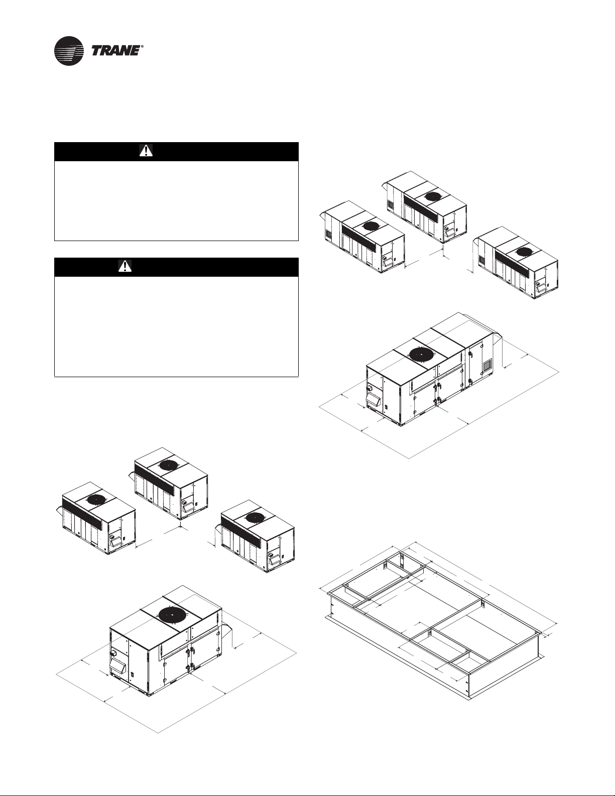
Unit Clearances
“Unit Clearances, Curb Dimensions, and Dimensional
Data,” p. 14 contains figures that illustrate the minimum
operating and service clearances for either a single or
multiple unit installation. These clearances are the
minimum distances necessary to assure adequate
serviceability, cataloged unit capacity, and peak operating
efficiency.
Providing less than the recommended clearances may
result in condenser coil starvation, “short-circuiting” of
exhaust or recirculation of hot condenser air.
• Avoid breathing fiberglass dust.
• Use a NIOSH approved dust/mist respirator.
• Avoid contact with the skin or eyes. Wear long-sleeved,
loose-fitting clothing, gloves, and eye protection.
OAU-SVX02F-EN 13
Page 14
Unit Clearances, Curb Dimensions, and Dimensional
7'-0"
6'-0"
END TO END
3'-0"
4'-0"
4'-0"
3'-0"
(1'72(1'
6833/<
5(7851
Data
WARNING
Combustible Materials!
Failure to maintain proper clearance between the unit
heat exchanger, vent surfaces and combustible
materials could cause a fire which could result in death
or serious injury or property damage. Refer to unit
nameplate and installation instructions for proper
clearances.
AVERTISSEMENT
Matériaux combustibles !
Tout manquement à l’obligation de maintenir une
distance appropriée entre l’échangeur de chaleur de
l’unité, les surfaces de ventilation et les matériaux
combustibles peut provoquer un incendie pouvant
résulter en des blessures corporelles graves, voire
mortelles, ou des dommages matériels. Reportez-vous
à la plaque signalétique de l’unité et aux instructions
d’installation pour connaître les distances appropriées.
OAB Units
Unit Clearances
Figure 1. Typical installation clearances for OAB unit
Figure 2. Typical installation clearances for OAB unit
with auxiliary cabinet
Note: Certain options require auxiliary cabinet. Refer to
project-specific unit submittals.
Curb Dimensions
Figure 3. Unit curb data for OAB 3–9 tons
14 OAU-SVX02F-EN
Page 15
Unit Clearances, Curb Dimensions, and Dimensional Data
5(7851
6833/<
)52179,(:
(/(&75,&
',6&211(&7
5,*+76,'(9,(:
5$
6$
%277209,(:
7+528*+%$6(
(/(&75,&
5,*+76,'(9,(:
Figure 4. Unit curb data for OAB 3–9 tons with
auxiliary cabinet
Note: Certain options require auxiliary cabinet. Refer to
project-specific unit submittals.
Dimensional Data
Figure 5. Unit dimensional data for OAB 3–9 tons (in.)
Note: Sound attenuation package will add 17.76 in. to the
height of the condenser fan section. Refer to
project-specific unit submittals.
OAU-SVX02F-EN 15
Page 16
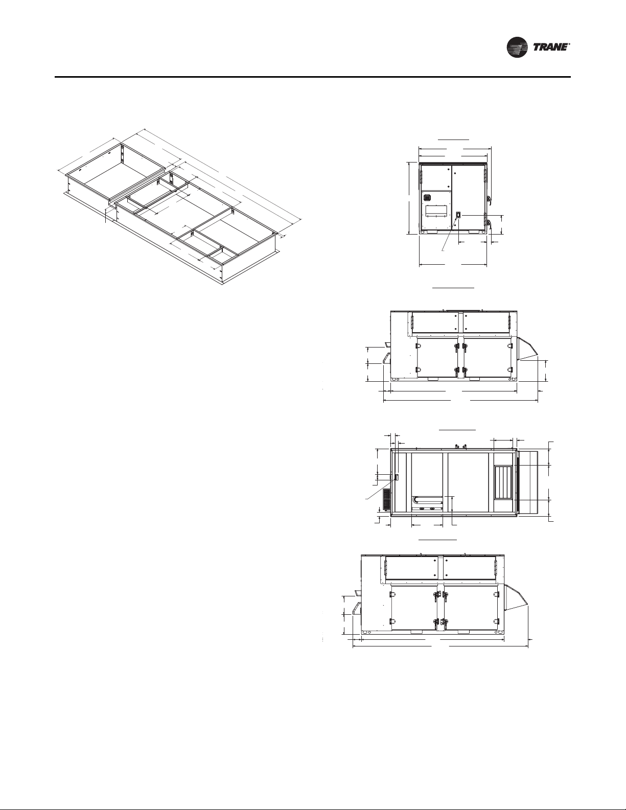
Unit Clearances, Curb Dimensions, and Dimensional Data
)52179,(:
(/(&75,&
',6&211(&7
5,*+76,'(9,(:
5$
6$
%277209,(:
7+528*+%$6(
(/(&75,&
72"
84"
36"
36"
48"
36"
Figure 6. Unit dimensional data for OAB 3–9 tons with
auxiliary cabinet (in.)
Indirect-Fired OAG Units
Unit Clearances
Figure 7. Typical installation clearances for indirect-
fired OAG unit
Note: Certain options require auxiliary cabinet. Refer to
project-specific unit submittals.
Note: Sound attenuation package will add 17.76 in. to the
height of the condenser fan section. Refer to
project-specific unit submittals.
16 OAU-SVX02F-EN
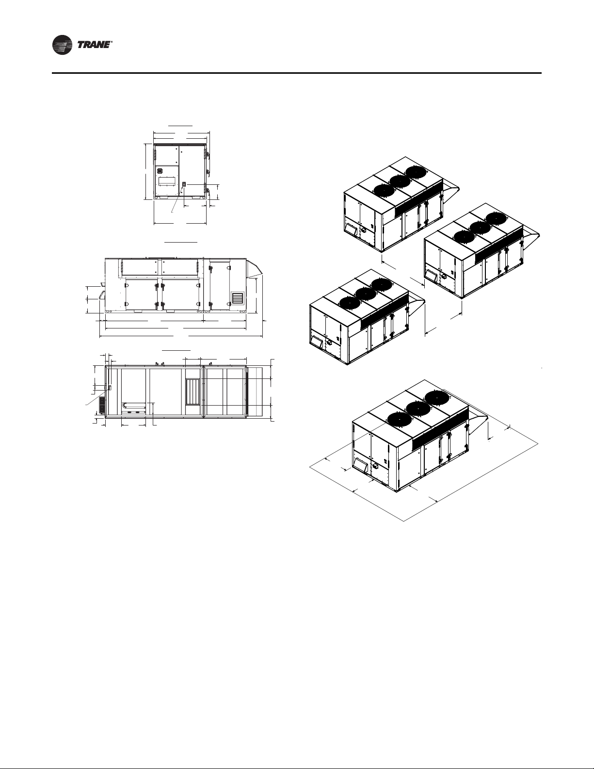
Page 17
Unit Clearances, Curb Dimensions, and Dimensional Data
72"
84"
36"
48"
36"
36"
S
U
P
P
L
Y
R
ET
U
R
N
4
13
3
55"
4
193"
3
"
" 23
4
3
53"
8
4
3
" 8
4
1
" 70
2
1
"
" 117
2
25
1
2
"
R
E
T
U
R
N
2
441"
84"
3
23
4
4
3
"
"
8
53"
3
8
1655"
1
" 70
2
1
"
" 117
2
3
55"
13
4
3
" 19
4
1
" 25
2
5
" 3
8
3
1
2
"
S
U
PPL
Y
17.250
35.798
ELECTRIC
DISCONNECT
FRONT VIEW
77.524
67.060
74.000
74.417
3.226
NECT
RIGHT SIDE VIEW
121.000 32.573 6.084
6.914
13.039
159.656
22.463
BOTTOM VIEW
17.250
5.125
22.000
24.500
SUPPLY
4.000
19.955
RETURN
11.000
52.000
RETURN
11.000
4.000
54.000
SUPPLY
2.000 THROUGH
BASE ELECTRIC
Figure 8. Typical installation clearances for indirect-
fired OAG unit with auxiliary cabinet
Figure 10. Unit curb data for indirect-fired OAG with
auxiliary cabinet (in.)
Note: Certain options require auxiliary cabinet. Refer to
project-specific unit submittals.
Dimensional Data
Figure 11. Unit dimensional data for indirect-fired OAG
Note: Certain options require auxiliary cabinet. Refer to
project-specific unit submittals.
Curb Dimensions
Figure 9. Unit curb data for indirect-fired OAG (in.)
OAU-SVX02F-EN 17
Page 18
Unit Clearances, Curb Dimensions, and Dimensional Data
17.250
35.798
ELECTRIC
DISCONNECT
FRONT VIEW
77.524
67.060
74.000
74.417
3.226
6.914
13.039
6.084
17.250
2.000 THROUGH
BASE ELECTRIC
BOTTOM VIEW
5.125
22.000
24.500
SUPPLY
52.072
19.955
RETURN
11.000
52.000
RETURN
11.000
4.000
54.000
SUPPLY
RIGHT SIDE VIEW
121.000 48.072
32.585
3.039
40.595
207.740
169.072
Note: Sound attenuation package will add 10.79 in. to the
height of the condenser fan section. Refer to
project-specific unit submittals.
Figure 12. Unit dimensional data for indirect-fired OAG
with auxiliary cabinet
Note: Certain options require auxiliary cabinet. Refer to
project-specific unit submittals.
Note: Sound attenuation package will add 10.79 in. to the
height of the condenser fan section. Refer to
project-specific unit submittals.
18 OAU-SVX02F-EN
Page 19
Unit Weight and Rigging
WARNING
Heavy Objects!
Failure to follow instructions below or properly lift unit
could result in unit dropping and possibly crushing
operator/technician which could result in death or
serious injury, and equipment or property-only damage.
Ensure that all the lifting equipment used is properly
rated for the weight of the unit being lifted. Each of the
cables (chains or slings), hooks, and shackles used to
lift the unit must be capable of supporting the entire
weight of the unit. Lifting cables (chains or slings) may
not be of the same length. Adjust as necessary for even
unit lift.
Improper Unit Lift!
Failure to properly lift unit could result in unit dropping
and possibly crushing operator/technician which could
result in death or serious injury, and equipment or
property-only damage. Test lift unit approximately
24 inches to verify proper center of gravity lift point. To
avoid dropping of unit, reposition lifting point if unit is
not level.
WARNING
AVERTISSEMENT
Levage inapproprié de l’unité !
AVERTISSEMENT
Objets lourds !
Le non-respect des instructions ci-dessous ou un levage
inapproprié de l’unité peut provoquer sa chute voire
écraser l’opérateur/le technicien, ce qui peut
occasionner des blessures graves voire mortelles, et
éventuellement endommager l’équipement ou
provoquer des dégâts matériels. Assurez-vous que
l’équipement de levage utilisé est adapté au poids de
l’unité à soulever. Chaque câble (chaîne ou élingue),
crochet ou manille utilisé pour le levage de l’unité doit
être assez robuste pour supporter le poids total de
l’unité. Les câbles, chaînes ou élingues de levage ne
doivent pas être de longueur identique. Procédez au
réglage afin de soulever l’unité de manière équilibrée.
Table 1. Typical unit weight, center of gravity, and corner weights (percentage of total weight) - air cooled DX units
without powered exhaust or ERV
Le non-respect des instructions ci-dessous ou un levage
inapproprié de l’unité peut provoquer sa chute voire
écraser l’opérateur/le technicien, ce qui peut
occasionner des blessures graves voire mortelles, et
éventuellement endommager l’équipement ou
provoquer des dégâts matériels. Faites un test de
levage de l’unité d’environ 60 cm (24 po) afin de vérifier
que le point de levage correspond au centre de gravité
de l’appareil. Pour éviter une chute de celle-ci, ajustez
son point de levage si elle n’est pas à l’horizontale.
Unit Weight
Weight (lb) Center-of-gravity (in.) Corner weight (% of total weight)
Model Number
OAB*036 1255 1736 46.1 24.1 28% 26% 27% 20%
OAB*048 1255 1736 46.6 23.9 30% 24% 28% 18%
OAB*060 1255 1736 45.9 23.9 29% 25% 28% 18%
OAB*072 1255 1736 47.5 23.8 31% 24% 27% 18%
OAB*084 1255 1736 46.5 24.0 29% 25% 28% 19%
OAB*096 1255 1736 46.7 24.1 31% 22% 30% 17%
OAB*108 1255 1736 46.2 24.0 27% 27% 25% 21%
OAG*120 2437 4546 60.2 34.7 29% 24% 26% 21%
OAG*144 2437 4546 59.5 34.9 26% 27% 24% 24%
OAG*180 2437 4546 59.3 34.7 28% 26% 26% 21%
OAG*210 2437 4546 60.7 35.5 26% 26% 24% 24%
OAG*240 2437 4546 59.5 34.6 29% 24% 26% 20%
OAG*264 2437 4546 59.9 34.4 26% 28% 23% 24%
OAG*300 2437 4546 58.8 35.2 28% 24% 27% 20%
OAG*360 2437 4546 58.9 34.2 28% 26% 25% 21%
OAU-SVX02F-EN 19
Min Max Length Width Corner A Corner B Corner C Corner D
Page 20
Unit Weight and Rigging
Table 2. Typical unit weight, center of gravity, and corner weights (percentage of total weight) - air cooled DX units
with powered exhaust but without ERV
Weight (lb) Center-of-gravity (in.) Corner weight (% of total weight)
Model Number
OAB*036 1608 2352 68.8 24.8 36% 17% 34% 14%
OAB*048 1608 2352 63.6 24.1 32% 22% 32% 14%
OAB*060 1608 2352 65.5 24.3 29% 24% 29% 18%
OAB*072 1608 2352 65.2 24.2 29% 25% 29% 18%
OAB*084 1608 2352 63.0 24.0 22% 32% 23% 23%
OAB*096 1608 2352 65.5 24.3 29% 24% 29% 18%
OAB*108 1608 2352 66.9 24.6 29% 24% 28% 19%
OAG*120 3199 4730 84.4 35.5 26% 26% 24% 24%
OAG*144 3199 4730 83.6 35.3 24% 28% 23% 25%
OAG*180 3199 4730 82.5 35.4 23% 29% 23% 25%
OAG*210 3199 4730 84.0 35.0 24% 29% 21% 26%
OAG*240 3199 4730 83.6 35.3 24% 28% 23% 25%
OAG*264 3199 4730 83.6 35.3 24% 28% 23% 25%
OAG*300 3199 4730 83.6 35.3 24% 28% 23% 25%
OAG*360 3199 4730 83.6 35.3 24% 28% 23% 25%
Min Max Length Width Corner A Corner B Corner C Corner D
Corner Weight
Table 3. Typical unit weight, center of gravity, and corner weights (percentage of total weight) - air cooled DX units
with powered exhaust and ERV
Weight (lb) Center-of-gravity (in.) Corner weight (% of total weight)
Model Number
OAB*036 1740 2526 68.1 24.3 31% 22% 29% 18%
OAB*048 1740 2526 68.9 24.0 31% 23% 27% 19%
OAB*060 1740 2526 67.0 24.1 28% 25% 26% 20%
OAB*072 1740 2526 67.0 24.4 25% 28% 24% 23%
OAB*084 1740 2526 68.3 24.4 28% 26% 25% 22%
OAB*096 1740 2526 67.3 24.2 30% 24% 28% 19%
OAB*108 1740 2526 68.1 24.0 28% 26% 25% 21%
OAG*120 3879 5972 89.4 35.3 28% 24% 23% 25%
OAG*144 3879 5972 84.3 38.8 23% 24% 26% 26%
OAG*180 3879 5972 88.1 35.1 25% 27% 21% 27%
OAG*210 3879 5972 88.2 35.2 31% 22% 26% 21%
OAG*240 3879 5972 87.4 35.2 29% 23% 25% 23%
OAG*264 3879 5972 85.8 35.1 24% 28% 21% 26%
OAG*300 3879 5972 87.0 36.0 27% 24% 24% 25%
OAG*360 3879 5972 87.0 36.0 27% 24% 24% 25%
Min Max Length Width Corner A Corner B Corner C Corner D
20 OAU-SVX02F-EN
Page 21

Unit Weight and Rigging
Intake
hood
OAB and OAG Cabinets - top view
BA
CD
/(1*7+
:,'7+
635($'(5
%$56
6&5(:3,16+$&./(
/2&$7,216
4-point lift
Model: OAB
/(1*7+
:,'7+
635($'(5
%$56
6&5(:3,16+$&./(
/2&$7,216
6-point lift
Model: OAB
SPREADER
BARS
A
DETAIL A
SCALE 1 : 12
SCREW PIN SHACKLE
4 LOCATIONS
4-point lift
Model: OAG
A
SPREADER
BARS
SCALE 1 : 12
DETAIL A
SCREW PIN SHACKLE
4 LOCATIONS
6-point lift
Model: OAG
Figure 13. Cabinet corners
Rigging
Figure 14. Rigging and center-of-gravity data
Figure 14. Rigging and center-of-gravity data
Before proceeding, refer to tables in Unit Weight section
for typical unit operating weights and Figure 14, p. 21 for
rigging drawing.
1. Remove the shipping crate from around the unit.
2. Rig the unit as shown in Figure 14, p. 21. Attach
adequate strength lifting slings to all four lifting
brackets in the unit base rail. Do not use cables, chains,
or slings except as shown.
3. Install a lifting bar, as shown in Figure 14, p. 21, to
protect the unit and to facilitate a uniform lift. The
minimum distance between the lifting hook and the
top of the unit should be 7 feet.
4. Test-lift the unit to ensure it is properly rigged and
balanced, make any necessary rigging adjustments.
5. Lift the unit and position it into place. Remove fork
pockets prior to setting on the curb.
OAU-SVX02F-EN 21
6. Downflow units; align the base rail of the unit with the
curb rail while lowering the unit onto the curb. Make
sure that the gasket on the curb is not damaged while
positioning the unit.
Page 22

Installation
48 in. (121.9 cm)
Minimum straight duct
distance before an elbow
for either gas heat
or electric heat
Airflow
WARNING
Hazardous Service Procedures!
Failure to follow all precautions in this manual and on
the tags, stickers, and labels could result in death or
serious injury.
Technicians, in order to protect themselves from
potential electrical, mechanical, and chemical hazards,
MUST follow precautions in this manual and on the
tags, stickers, and labels, as well as the following
instructions: Unless specified otherwise, disconnect all
electrical power including remote disconnect and
discharge all energy storing devices such as capacitors
before servicing. Follow proper lockout/tagout
procedures to ensure the power can not be
inadvertently energized. When necessary to work with
live electrical components, have a qualified licensed
electrician or other individual who has been trained in
handling live electrical components perform these
tasks.
AVERTISSEMENT
Procédures d’entretien dangereuses !
Le non-respect de toutes les précautions contenues
dans ce manuel ainsi que sur les étiquettes et les
autocollants peut entraîner des blessures graves voire
mortelles. Les techniciens, afin d’être protégés des
éventuels risques électriques, mécaniques et
chimiques, DOIVENT suivre les précautions contenues
dans ce manuel, sur les étiquettes et les autocollants,
ainsi que les instructions suivantes : Sauf indication
contraire, coupez toute l’alimentation électrique y
compris les disjoncteurs à distance et déchargez tous
les dispositifs de stockage d’énergie comme les
condensateurs avant l’entretien. Respectez les
procédures de verrouillage et d’étiquetage appropriées
pour éviter tout risque de remise sous tension
accidentelle. S’il est nécessaire de travailler avec des
composants électriques sous tension, demandez à un
électricien qualifié et agréé ou à une autre personne
ayant la formation nécessaire pour manipuler des
composants électriques sous tension d’exécuter ces
tâches.
Ductwork
Elbows with turning vanes or splitters are recommended
to minimize air noise due to turbulence and to reduce static
pressure.
When attaching the ductwork to the unit, provide a watertight flexible connector at the unit to prevent operating
sounds from transmitting through the ductwork.
All outdoor ductwork between the unit and the structure
should be weather proofed after installation is completed.
Note: For sound consideration, cut holes in the roof deck
only for the ductwork penetrations. Do not cut out
the roof deck within the entire curb perimeter. All
duct work must be installed and connected to top of
roof curb before the unit is set on curb.
If a Curb Accessory Kit is not used:
1. Be sure to use flexible duct connections at the unit.
2. Gaskets must be installed around the curb perimeter
flange and the supply and return air opening flanges.
Note: For units will electric heat in the primary heating
position, refer to figure below.
Figure 15.
Important: Bottom discharge units with open coil
electric heater in primary heat location
require discharge duct with 90° elbow. This
is a MANDATORY installation requirement.
Note: A minimum 48" of straight duct is required before
an elbow. This is a requirement for both vertical
and horizontal discharge regardless of heat type.
General Unit Requirements
The checklist listed below is a summary of the steps
required to successfully install a commercial unit. This
checklist is intended to acquaint the installing personnel
with what is required in the installation process. It does
not replace the detailed instructions called out in
the applicable sections of this manual.
Check the unit for shipping damage and material
shortage. File a freight claim and notify appropriate
sales representative if damage or shortage is
discovered.
Verify that the unit nameplate model, options, and
voltage are correct.
Verify that the installation location of the unit will
provide the required clearance for proper operation.
22 OAU-SVX02F-EN
Page 23

Installation
Control
panel
door
Heater
door
Assemble and install the roof curb (if applicable).
Refer to the latest edition of the curb installers guide
that ships with each curb kit. Check curb for level
installation; if not level, shim as required.
Convert unit to horizontal discharge and/or horizontal
return if necessary (Refer to “OAB and OAG IF Heater
Air Inlet Hood and Flue Assembly Instructions,” p. 23).
Rigging unit (refer to “Unit Weight and Rigging,”
p. 19).
Set the unit onto the curb; check for level.
Ensure unit-to-curb seal is tight and without buckles
or cracks.
Install and connect proper condensate drain line to
the evaporator condensate pan drain connection (see
Figure 24, p. 25).
Assemble indirect fired heater air inlet hood and flue
assembly (refer to “OAB and OAG IF Heater Air Inlet
Hood and Flue Assembly Instructions,” p. 23.)
OAB and OAG IF Heater Air Inlet Hood and
Flue Assembly Instructions
Unit is shipped with the IF heater air inlet hood and flue
cover stowed in the blower compartment.
Important: Assemble the inlet hood and flue cover to
the heater door before attempting any unit
startup.
Figure 17. Wind screen
Figure 18. Heater air inlet hood
Figure 16. Flue cover
1. Open the blower compartment and remove the flue
cover, wind screen, and heater air inlet hood.
2. Open the control panel door and remove the heater
door shown in Figure 19.
Figure 19.
OAU-SVX02F-EN 23
Page 24

Installation
3. Attach the flue cover to the heater door using the
provided stainless steel screws as shown in Figure 20.
Figure 20.
4. Attach the heater air inlet hood to the heater door using
quantity (6) of the provided painted head screws as
shown in Figure 21.
Figure 22.
6. Install the heater door on the unit, as shown in
Figure 23, p. 24, ensuring that the heater flue extends
through the flue opening in the door.
Figure 23.
Figure 21.
5. Attach the wind screen to the inside of the heater door
using quantity (6) of the provided painted head screws
as shown in Figure 22.
24 OAU-SVX02F-EN
Page 25

Installation
PANEL ENCLOSURE
D" NPT FEMALE
CONNECTOR
CLEANOUT PLUG
Main Electrical Power Requirements
Verify that the power supply complies with the unit
nameplate specifications.
Inspect all control panel components; tighten any
loose connections.
Connect properly sized and protected power supply
wiring to a field-supplied/-installed disconnect switch
and to the main power terminal block (HTB1) in the
unit control panel.
Connect properly-sized earth ground.
Note: All field-installed wiring must comply with NEC
and applicable local codes.
Condensate Drain Configuration
OAU units are selected based on dehumidification
capability. As such, condensate can form at a high rate.
Therefore, the OAU drain pan and condensate line are
sized and designed accordingly. However, an oftenoverlooked element of proper condensate drainage is
proper P-Trap and drain line sizing and installation. An
incorrectly-designed and -installed P-Trap can restrict
condensate flow or cause water in the condensate drain
pan to “spit” or “geyser” which may cause condensate
overflow. Carefully install and trap the drain pan to ensure
adequate condensate removal under all conditions.
An evaporator condensate drain connection is provided
on the unit.
A condensate trap must be installed at the unit due to the
drain connection being on the “negative pressure” side of
the fan. Install the P-Trap using the guidelines in Figure 24.
Pitch drain lines connected to P-Trap at least 1/2 inch for
every 10 feet of horizontal run to assure proper
condensate flow. Do not allow the horizontal run to sag
causing a possible double-trap condition which could
result in condensate backup due to “air lock”.
Figure 24. Condensate trap installation
D = Pipe diameter; see for correct pipe diameter
H = Internal static pressure (in wg) +1 in.
J = H x 0.5
L = H + J +D
Notes:
1. Pitch drain at least 1/2 in. per 10 ft horizontal run.
2. Condensate drain pan will not drain properly if P-trap is not primed
and of adequate height to allow for cabinet operating negative
pressure.
Hot Water Control Valve Wiring
1. Mount the factory-provided water valve on the return
line of the hot water coil.
2. Ensure the valve is set to normally open.
3. Run the 16 gauge black wire from TNS 2 to Input 1 of
the actuator.
4. Run the 16 gauge red wire from TNS 2 to Input 2 of the
actuator.
5. Run the 16 gauge yellow wire from AO1 from the
UC600 to Input 3 of the actuator.
Note: The actuator valve will be open with a 0 percent
call for heat.
Figure 25. Hot water control valve wiring
OAU-SVX02F-EN 25
Page 26

Installation
&
$
(
%
'
'(7$,/$
6&$/(
7RUH
KH[KH
VLGHV
/LIWW
VLGHS
WRSXS
$VV
VHFXUH
KRRG
VFUHZV
WKHSU
VLGHS
5HS
GDPS
Chilled Water Connection Size and
Location
Figure 26. Outdoor air chilled water cooling pipe chase-
connections
Figure 27. OAB powered exhaust damper hood,
collapsed
Table 4. Chilled water pipe chase location (in.)
Unit A B C D E
OAB 61.25 12 10 3 3
OAG 79.75 12.5 10 3 4.125
Table 5. Chilled water connection size (MPT-in.)
Unit Size MPT-in.
OAB 3–9 tons 2
OAG 10–30 tons 2
Filter Installation
The filter rack is accessible through the evaporator coil
compartment door. Filter type, size, and quantity are
determined by selected filter option and unit size.
Note: Do not operate the unit without filters.
Opening the Collapsed Exhaust Damper
2. Lift the hood upward and rotate the side panels
outward while holding the top up.
3. As shown in DETAIL B (see Figure 28) and marked by
arrow (2), secure the side panels to the top of the hood
using (8) hex head sheet metal screws, provided with
the unit, through the pre-punched holes in the top and
side panels (four screws per side).
4. Repeat these steps for the remaining damper hood.
Hood
OAB Cabinet
1. To release the damper hood, remove the hex head
sheet metal screws (one per side) shown in DETAIL A
(see Figure 27) and marked by arrow (1).
26 OAU-SVX02F-EN
Page 27

Installation
'(7$,/%
6&$/(
WKH
WKH
JK
'(7$,/$
6&$/(
7RUHOH
WKHKH[
VKRZQLQ
/LIWWKH
VLGHSDQ
WRSXS
$VVKR
VHFXUHW
KRRGXV
VFUHZV
WKHSUH
VLGHSDQ
5HSHD
Figure 28. OAB powered exhaust damper hood, open
Figure 29. OAG powered exhaust damper hood,
collapsed
OAG Cabinet
1. To release damper hood, remove the hex head sheet
metal screw shown in DETAIL A (see Figure 29) and
marked by arrow (1).
2. Lift the hood upward and rotate the side panels
outward while holding the top up.
3. As shown in DETAIL B (see Figure 30) and marked by
arrow (2), secure the side panels to the top of the hood
using (8) hex head sheet metal screws, provided with
the unit, through the pre-punched holes in the top and
side panels (four screws per side).
4. Repeat these steps for the remaining damper hood.
OAU-SVX02F-EN 27
Page 28

Installation
'(7$,/%
6&$/(
WKH
(/(&75,&
',6&211(&7
6:,7&+
*$6,1/(7
037
&21'(16$7(
'5$,1
)37
7+528*+%$6(
(/(&75,&
OAB utility
connections
GAS INLET
1-1/4" MPT
CONDENSATE
DRAIN
1/2" FPT
ELECTRIC
DISCONNECT
SWITCH
81.248
5.512
17.253
38.346
6.000
6.830
OAG utility
connections
Figure 30. OAG powered exhaust damper hood, open
AVERTISSEMENT
Câblage sur site et mise à la terre corrects
nécessaires !
Le non-respect de la réglementation peut entraîner des
blessures graves, voire mortelles. Il est IMPÉRATIF de
confier l’ensemble du câblage sur site à un électricien
qualifié. Un câblage sur site mal installé ou mal mis à la
terre constitue des risques D’INCENDIE et
D’ÉLECTROCUTION. Pour éviter ces risques, il est
IMPÉRATIF de respecter les obligations en matière de
pose de câblage sur site et de mise à la terre tel que
stipulé dans les règles du NEC et dans les
réglementations électriques locales/nationales.
An overall dimensional layout for the standard field
installed wiring entrance into the unit is illustrated in . To
ensure that the unit’s supply power wiring is properly sized
and installed, refer to the following guidelines.
Figure 31. OAB and OAG utility connections
Field Installed Power Wiring
WARNING
Proper Field Wiring and Grounding
Required!
Failure to follow code could result in death or serious
injury. All field wiring MUST be performed by qualified
personnel. Improperly installed and grounded field
wiring poses FIRE and ELECTROCUTION hazards. To
avoid these hazards, you MUST follow requirements for
field wiring installation and grounding as described in
NEC and your local/state electrical codes.
28 OAU-SVX02F-EN
Note: All field installed wiring must conform to NEC
guidelines as well as State and Local codes.
Page 29

Verify that the power supply available is compatible with
the unit’s nameplate ratings. The available supply power
must be within 10 percent of the rated voltage stamped on
the nameplate. Use only copper conductors to connect the
power supply to the unit.
Main Unit Power
WARNING
Hazardous Voltage!
Failure to disconnect power before servicing could
result in death or serious injury. Disconnect all electric
power, including remote disconnects before servicing.
Follow proper lockout/tagout procedures to ensure the
power can not be inadvertently energized.Verify that no
power is present with a voltmeter.
AVERTISSEMENT
Risque d’électrocution !
Le non-respect de cette consigne peut entraîner des
blessures graves, voire mortelles. Avant toute
intervention, coupez l’alimentation électrique, y
compris aux sectionneurs à distance. Suivez
scrupuleusement les procédures de verrouillage/mise
hors service préconisées pour empêcher tout
rétablissement accidentel de l’alimentation électrique.
NOTICE
Use Copper Conductors Only!
Failure to use copper conductors could result in
equipment damage as unit terminals are not designed
to accept other types of conductors.
Standard Wiring
WARNING
Proper Field Wiring and Grounding
Required!
Failure to follow code could result in death or serious
injury. All field wiring MUST be performed by qualified
personnel. Improperly installed and grounded field
wiring poses FIRE and ELECTROCUTION hazards. To
avoid these hazards, you MUST follow requirements for
field wiring installation and grounding as described in
NEC and your local/state electrical codes.
Installation
AVERTISSEMENT
Câblage sur site et mise à la terre corrects
nécessaires !
Le non-respect de la réglementation peut entraîner des
blessures graves, voire mortelles. Il est IMPÉRATIF de
confier l’ensemble du câblage sur site à un électricien
qualifié. Un câblage sur site mal installé ou mal mis à la
terre constitue des risques D’INCENDIE et
D’ÉLECTROCUTION. Pour éviter ces risques, il est
IMPÉRATIF de respecter les obligations en matière de
pose de câblage sur site et de mise à la terre tel que
stipulé dans les règles du NEC et dans les
réglementations électriques locales/nationales.
The electrical service must be protected from over current
and short circuit conditions in accordance with NEC
requirements. Protection devices must be sized according
to the electrical data on the nameplate.
1. Location of the electrical service entrance is illustrated
in. Complete the unit’s power wiring connections onto
either; the main terminal block HTB1 inside the unit
control panel, the factory mounted non-fused
disconnect switch (UCD) or circuit breaker (UCB), or
the electric heat non-fused disconnect switch. Refer to
the customer connection diagram that shipped with
the unit for specific termination points.
2. Provide proper grounding for the unit in accordance
with local and national codes.
Use the following checklist in conjunction with the
checklist in “General Unit Requirements,” p. 22 to ensure
that the unit is properly installed and ready for operation.
Verify that the correct size and number of filters are in
place.
Inspect the interior of the unit for tools and debris and
install all panels in preparation for starting the unit.
Check all electrical connections for tightness and
“point of termination” accuracy.
Verify condenser airflow is unobstructed.
Verify that the condenser and indoor fans turn freely
without rubbing and are properly tightened on the
shafts.
Check motor mounting bolts and inlet cone for
tightness. Free spin wheel by hand to check for proper
alignment of motor, wheel, and inlet cone. Record
motor nameplate amps at unit-rated voltage.
Check proper indoor fan wheel rotation. Wheel
housing will be marked to indicate direction of proper
rotation.
With access doors closed and secured, operate
blower at 100 percent speed. Check amps to confirm
operation within motor amp capacity.
OAU-SVX02F-EN 29
Page 30

Installation
Voltage Imbalance
WARNING
Live Electrical Components!
Failure to follow all electrical safety precautions when
exposed to live electrical components could result in
death or serious injury. When it is necessary to work
with live electrical components, have a qualified
licensed electrician or other individual who has been
properly trained in handling live electrical components
perform these tasks.
AVERTISSEMENT
Composants électriques sous tension !
Le non-respect de toutes les consignes de sécurité lors
de la manipulation de composants électriques sous
tension peut entraîner des blessures graves, voire
mortelles. S’il est nécessaire de travailler avec des
composants électriques sous tension, demandez à un
électricien qualifié et agréé ou à une autre personne
ayant la formation nécessaire pour manipuler des
composants électriques sous tension d’exécuter ces
tâches.
Three phase electrical power to the unit must meet
stringent requirements for the unit to operate properly.
Measure each leg (phase-to-phase) of the power supply.
Each reading must fall within the utilization range stamped
on the unit nameplate. If any of the readings do not fall
within the proper tolerances, notify the power company to
correct this situation before operating the unit.
Excessive three phase voltage imbalance between phases
will cause motors to overheat and eventually fail. The
maximum allowable voltage imbalance is 2.0 percent.
Measure and record the voltage between phases 1, 2, and
3 and calculate the amount of imbalance as follows:
% Voltage Imbalance = 100 X
AV (Average Voltage) =
V1, V2, V3 = Line Voltage Readings
VD = Line Voltage reading that deviates the farthest from
the average voltage.
Example: If the voltage readings of the supply power
measured 221, 230, and 227, the average volts would be:
221 + 230 + 227
3
= 226 Avg.
AV - VD
AV
Volt 1 + Volt 2 + Volt 3
where;
3
100 X
The 2.2 percent imbalance in this example exceeds the
maximum allowable imbalance of 2.0 percent. This much
imbalance between phases can equal as much as a
20 percent current imbalance with a resulting increase in
motor winding temperatures that will decrease motor life.
If the voltage imbalance is over 2.0 percent, notify the
proper agencies to correct the voltage problem before
operating this equipment.
226 - 221
226
= 2.2%
Electrical Phasing (Three-Phase Motors)
WARNING
Live Electrical Components!
Failure to follow all electrical safety precautions when
exposed to live electrical components could result in
death or serious injury. When it is necessary to work
with live electrical components, have a qualified
licensed electrician or other individual who has been
properly trained in handling live electrical components
perform these tasks.
AVERTISSEMENT
Composants électriques sous tension !
Le non-respect de toutes les consignes de sécurité lors
de la manipulation de composants électriques sous
tension peut entraîner des blessures graves, voire
mortelles. S’il est nécessaire de travailler avec des
composants électriques sous tension, demandez à un
électricien qualifié et agréé ou à une autre personne
ayant la formation nécessaire pour manipuler des
composants électriques sous tension d’exécuter ces
tâches.
The compressor motor(s) and the supply fan motor are
internally connected for the proper rotation when the
incoming power supply is phased as A to L1, B to L2, and
C to L3.
Proper electrical supply phasing can be quickly
determined and corrected before starting the unit by using
an instrument such as an Associated Research Model 45
Phase Sequence Indicator and following these steps:
Turn off the main source feeding power to the unit
field-supplied or factory-installed main disconnect
device (switch or circuit breaker).
Close the unit disconnect device cover, leaving
disconnect switch in the off position, and turn main
source power on.
VD (reading farthest from average) = 221
The percentage of Imbalance equals:
30 OAU-SVX02F-EN
Page 31

Installation
Observe the ABC and CBA phase indicator lights on
the face of the sequencer. The ABC indicator light will
glow if the phase is ABC. If the CBA indicator light
glows, turn main source power off and then open the
unit main disconnect device cover and reverse any
two power wires.
Restore the main source power and recheck the
phasing. If the phasing is correct, turn main source
power off then open the unit main disconnect device
cover, remove the phase sequence indicator, reinstall
disconnect device cover and, leaving disconnect
device in the off position, turn main power source to
unit on.
Compressor Crankcase Heaters
WARNING
Live Electrical Components!
Failure to follow all electrical safety precautions when
exposed to live electrical components could result in
death or serious injury. When it is necessary to work
with live electrical components, have a qualified
licensed electrician or other individual who has been
properly trained in handling live electrical components
perform these tasks.
AVERTISSEMENT
Composants électriques sous tension !
Le non-respect de toutes les consignes de sécurité lors
de la manipulation de composants électriques sous
tension peut entraîner des blessures graves, voire
mortelles. S’il est nécessaire de travailler avec des
composants électriques sous tension, demandez à un
électricien qualifié et agréé ou à une autre personne
ayant la formation nécessaire pour manipuler des
composants électriques sous tension d’exécuter ces
tâches.
To prevent injury or death from electrocution, it is the
responsibility of the technician to recognize this hazard
and use extreme care when performing service
procedures with the electrical power energized.
Each compressor shall be equipped with a crankcase
heater. The proper operation of the crankcase heater is
important to maintain an elevated compressor oil
temperature during the “Off” cycle to reduce oil foaming
during compressor starts. Oil foaming occurs when
refrigerant condenses in the compressor and mixes with
the oil. In lower ambient conditions, refrigerant migration
to the compressor could increase.
When the compressor starts, the sudden reduction in
crankcase pressure causes the liquid refrigerant to boil
rapidly causing the oil to foam. This condition could
damage compressor bearings due to reduced lubrication
and could cause compressor mechanical failures.
Before initial start up, or if main power has been off for an
extended period of time, compressor crankcase heater(s)
should be operated for a minimum of 8 hours prior to
compressor operation. With main power OFF, remove
jumper between OAUTS terminals 9 and 10 (E-Stop). Turn
main power to energize crankcase heater(s). At end of
warm up period turn main power off, install 9-10 jumper,
turn main power on, and resume normal operation.
Following crankcase heater warm-up, turn main power
disconnect off, and install jumper on E-Stop terminals 9
and 10.
Turn Main disconnect “On”.
Main Unit Display and ReliaTel Controls
When first powered “On”, the controls perform selfdiagnostic initialization to check that all internal controls
are functional. The Status LED located on the Main Unit
Display and the Liteport LED located on the RTRM module
is turned “On” within one second of power-up if internal
operation is okay.
Field-Installed Control Wiring
WARNING
Proper Field Wiring and Grounding
Required!
Failure to follow code could result in death or serious
injury. All field wiring MUST be performed by qualified
personnel. Improperly installed and grounded field
wiring poses FIRE and ELECTROCUTION hazards. To
avoid these hazards, you MUST follow requirements for
field wiring installation and grounding as described in
NEC and your local/state electrical codes.
AVERTISSEMENT
Câblage sur site et mise à la terre corrects
nécessaires !
Le non-respect de la réglementation peut entraîner des
blessures graves, voire mortelles. Il est IMPÉRATIF de
confier l’ensemble du câblage sur site à un électricien
qualifié. Un câblage sur site mal installé ou mal mis à la
terre constitue des risques D’INCENDIE et
D’ÉLECTROCUTION. Pour éviter ces risques, il est
IMPÉRATIF de respecter les obligations en matière de
pose de câblage sur site et de mise à la terre tel que
stipulé dans les règles du NEC et dans les
réglementations électriques locales/nationales.
An overall layout of the various control options available
with the required number of conductors for each control
device is illustrated in Figure 32, p. 33.
Note: All field wiring must conform to NEC guidelines as
well as state and local codes.
OAU-SVX02F-EN 31
Page 32

Installation
Control Power Transformer
WARNING
Hazardous Voltage!
Failure to disconnect power before servicing could
result in death or serious injury. Disconnect all electric
power, including remote disconnects before servicing.
Follow proper lockout/tagout procedures to ensure the
power can not be inadvertently energized.Verify that no
power is present with a voltmeter.
AVERTISSEMENT
Risque d’électrocution !
Le non-respect de cette consigne peut entraîner des
blessures graves, voire mortelles. Avant toute
intervention, coupez l’alimentation électrique, y
compris aux sectionneurs à distance. Suivez
scrupuleusement les procédures de verrouillage/mise
hors service préconisées pour empêcher tout
rétablissement accidentel de l’alimentation électrique.
The 24-volt control power transformers are to be used only
with the accessories called out in this manual.
Transformers rated greater than 50 VA are equipped with
internal circuit breakers. If a circuit breaker trips, turn “Off”
all power to the unit before attempting to reset it.
The transformers are located in the control panel. The
circuit breaker is located on the left side of the
transformers and can be reset by pressing in on the black
reset button.
Controls Using 24 Vac
NOTICE
Use Copper Conductors Only!
Failure to use copper conductors could result in
equipment damage as unit terminals are not designed
to accept other types of conductors.
Before installing any connecting wiring, refer to the below
table for AC conductor sizing guidelines, and:
1. Use copper conductors unless otherwise specified.
2. Ensure that the AC control wiring between the controls
and the unit’s termination point does not exceed three
(3) ohms/ conductor for the length of the run.
Note: Resistance in excess of 3 ohms per conductor
may cause component failure due to
insufficient AC voltage supply.
3. Be sure to check all loads and conductors for grounds,
shorts, and mis-wiring.
4. Do not run the AC low-voltage wiring in the same
conduit with the high-voltage power wiring.
Table 6. 24 Vac conductors
Distance from Unit to Control Recommended Wire Size
000–460 feet
000–140 m
461–732 feet
104–223 m
18 gauge
0.75 mm
16 gauge
1 mm
2
2
Controls Using DC Analog Input/Output
(Standard Low Voltage Multiconductor
Wire)
WARNING
Hazardous Voltage!
Failure to disconnect power before servicing could
result in death or serious injury. Disconnect all electric
power, including remote disconnects before servicing.
Follow proper lockout/tagout procedures to ensure the
power can not be inadvertently energized.Verify that no
power is present with a voltmeter.
AVERTISSEMENT
Risque d’électrocution !
Le non-respect de cette consigne peut entraîner des
blessures graves, voire mortelles. Avant toute
intervention, coupez l’alimentation électrique, y
compris aux sectionneurs à distance. Suivez
scrupuleusement les procédures de verrouillage/mise
hors service préconisées pour empêcher tout
rétablissement accidentel de l’alimentation électrique.
32 OAU-SVX02F-EN
Risque d’électrocution !
Le non-respect de cette consigne peut entraîner des
blessures graves, voire mortelles. Avant toute
intervention, coupez l’alimentation électrique, y
compris aux sectionneurs à distance. Suivez
scrupuleusement les procédures de verrouillage/mise
hors service préconisées pour empêcher tout
rétablissement accidentel de l’alimentation électrique.
Before installing any connecting wiring between the unit
and components utilizing a DC analog input\output signal,
refer to the electrical access locations provided on the unit.
WARNING
AVERTISSEMENT
Page 33

Installation
1. Below table lists the conductor sizing guidelines that
must be followed when interconnecting the DC binary
output devices and the system components utilizing a
DC analog input\output signal to the unit.
Note: Resistance in excess of 2.5 ohms per conductor
can cause deviations in the accuracy of the
controls.
2. Ensure that the wiring between controls and the unit’s
termination point does not exceed 2.5 ohms/
conductor for the length of the run.
3. Do not run the electrical wires transporting DC signals
in or around conduit housing high voltage wires.
Figure 32. OAUTS connection B
DC Conductors
Table 7. Zone sensor module wiring
Distance from Unit to Control Recommended Wire Size
000–150 feet
0–45.7 m
151–240 feet
46–73.1 m
241–385 feet
73.5–117.3 m
386–610 feet
117.7–185.9 m
611–970 feet
186.2–295.7 m
22 gauge
0.33 mm
20 gauge
0.50 mm
18 gauge
0.75 mm
16 gauge
1.3 mm
14 gauge
2.0 mm
2
2
2
2
2
Factory-Provided Sensors
installation in the return duct. Refer to Figure 42, p. 60 for
installation instructions.
A discharge temperature sensor (VELSEN-0021) will be
factory-provided for field installation in the supply duct.
Refer to Figure 39, p. 57 for installation instructions.
If space control is selected, a combination space
temperature/humidity sensor (BAYSENS036A) will be
factory-provided for field installation in the space. Refer to
Figure 40, p. 58 for installation instructions.
If multi-zone VAV control is selected, a static pressure
sensor (VELCON-0350) will be factory-provided for field
installation in the supply duct or space. Refer to Figure 42,
p. 60 for installation instructions.
If modulating OA/RA dampers w/economizer and an
exhaust fan are selected, a duct static pressure sensor
(VELCON-0350) will be factory-provided for field
OAU-SVX02F-EN 33
Page 34

Pre-Start Check List
Task Initial Date
1. Voltage is present and landed at equipment.
2. Gas piping is complete and landed at each component. Inlet gas pressure
to be between 7 in. wg and 14 in. wg.
3. Field installed sensors installed. Refer to “Factory-Provided Sensors,” p. 33
for list of sensors that may be required.
4. Control wiring installed and landed.
5. Accessories installed.
6. Ductwork installed (all runs in place, final tie in complete).
7. Drain lines installed and properly terminated.
8. Startup appointment with Horizon certified Trane service technician set and
confirmed.
Notes:
• Check list must be completed and returned to Trane before startup is scheduled.
• Startup must be performed by a Horizon-certified Trane technician with Tracer™ TU program.
• Contractor to furnish access to equipment (ladder, lift, or roof access).
34 OAU-SVX02F-EN
Page 35

System Configuration and Pre-Start
The following procedure must be completed prior to
performing the startup procedure in “Startup,” p. 38. This
section describes procedures to navigate the various
displays on the Unit Display and configure the Outdoor Air
Unit Main Unit Display system setpoints and operating
parameters.
Important: This section is intended to provide
guidelines for navigation through the
remote operator display screens. For
additional control system information, refer
to Integration Guide: Tracer™ UC600
Programmable Controller for Packaged
Outdoor Air Unit (BAS-SVP18*-EN).
OAU-SVX02F-EN 35
Page 36

System Configuration and Pre-Start
Table 8. Menu descriptions
Screen Menu Point List Min/Inactive Default Max/Active
Alarms
Reports
(continued
on next
page)
Active Alarms List of all active alarms
All Alarms List of all previous alarms
Custom Graphics *NOT USED*
Program Control Discharge Air Control Space ControlSpace ControlY
Heat Cool Mode Active Heat — Cool N
Occupancy Status Occupied|Unoccupied|Occupied Bypass|Occupied Standby|Unknown Y
Compressor 1 Command Off — On N
Digital Scroll Command 0% — 100% N
Dehumidification Command Disabled Enabled N
Discharge Air Temperature Local Analog Input
Economizer Mode Disabled Enabled N
Evap Leaving Temp Local Analog Input
Heat Capacity 0% — 100% N
Heating Output Command 0% — 100% N
Heat 1 Command Off — On N
Heat 2 Command Off — On N
Inducer Command Off — On N
Gas Valve Status Binary Input
HGRH Command 0% — 100% N
OA Damper End Switch Binary Input
Outdoor Air Damper Command Closed — Open N
OAD Position Local Binary Input
Outdoor Air Relative Humidity Local Analog Input
Outdoor Air Temperature Local Analog Input
System Status
Space Dewpoint Active Analog Input
Space Temperature Local Analog Input
Supply Fan Start Stop Command Off — Off N
Filter Status Clean — Dirty N
System Lockout Normal Normal Lockout N
UNOCC Cooling Mode Off — On N
UNOCC Dehumid Mode Off — On N
UNOCC Heating Mode Off — On N
ERV Command Disable — Enable N
ERV Leaving Air Temperature Local Analog Input
PEVFD Command 0% 80% 100% Y
Discharge Airflow Local Analog Input
ERV Leaving Air Humidity Local Analog Input
BAS
Point?
36 OAU-SVX02F-EN
Page 37

System Configuration and Pre-Start
Table 8. Menu descriptions (continued)
Screen Menu Point List Min/Inactive Default Max/Active
DAT High Temp Cutout 100°F 125°F 150°F Y
DAT Low Temp Cutout 35°F 35°F 50°F Y
DAT Temp Cutout Time 10 min. 10 min. 25 min. Y
Discharge Air Cooling Setpoint 55°F 55°F 75°F Y
Discharge Air Heating Setpoint 65°F 85°F 90°F Y
ERV Wheel Frost Cutout Setpoint 32°F 34°F 40°F Y
EVAP Leaving Temp Setpoint 45°F 53°F 70°F Y
IVFD Signal 50% 100% 100% Y
Maximum Discharge Air Temperature 70°F 90°F 100°F Y
Minimum Discharge Air Cooling Setpoint 40°F 50°F 65°F Y
Minimum Discharge Air Heating Setpoint 50°F 55°F 60°F Y
System Setpoints
Reports
(continued
from
previous
page)
System Setup
Override Summary List of active overrides - same as selecting Override button at top of screen
All Point Report List of all points (AO/AI/BO/BI/MS/etc …) in the configuration file
About Co ntroller Name listed is the version of the program installed in the UC600
Expansion Modules Provides status of expansion modules
TGP2 Programs List of all TGP2 programs loaded on the UC600
Data Graphs *NOT USED*
Schedules - Refer to UC600 IOM for scheduling functions
Display Preferences
Settings
Language
Date and Time
Clean Touchscreen
Maximum OA Damper Position 0% 100% 100% Y
Minimum OA Damper Position 0% 100% 100% Y
Occupied Space Cooling Setpoint 65°F 74°F 90°F Y
Occupied Space Heating Setpoint 60°F 70°F 75°F Y
Outdoor Air Cooling Setpoint (OACS) 70°F 75°F 85°F Y
Outdoor Air Dewpoint Setpoint (OADS) 49°F 58°F 65°F Y
Outdoor Air Heating Setpoint (OAHS) 40°F 70°F 70°F Y
PEVFD Setpoint 0% 80% 100% Y
Space Dewpoint Setpoint (SPDS) 50°F 59°F 68°F Y
UNOCC Space Cooling Setpoint 60°F 80°F 90°F Y
UNOCC Space Dewpoint Setpoint 49°F 65°F 68°F Y
UNOCC Space Heating Setpoint 50°F 60°F 70°F Y
Program Control Discharge Air Control Space ControlSpace ControlY
Compressor Count 004N
Heater Count 002N
Split Manifold Burner Not Installed Installe d Installed N
ERV Option Not Installed Installed Installed N
Powered Exhaust Option Not Installed Installed Installed N
Return Air Damper Option Not Installed Installed Installed N
Space Temp/Humidity Sensor Installed Not Installed Installed Installed N
Heat Type No Heat|Gas Heat|Electric Heat|Other N
Alarm Reset Off Off On Y
Supply Fan Failure Reset Off Off On Y
BAS
Point?
OAU-SVX02F-EN 37
Page 38

Startup
Indirect Gas-Fired Heating
Startup
WARNING
Hazardous Service Procedures!
Failure to follow all precautions in this manual and on
the tags, stickers, and labels could result in death or
serious injury.
• Technicians, in order to protect themselves from
potential electrical, mechanical, and chemical
hazards, MUST follow precautions in this manual and
on the tags, stickers, and labels, as well as the
following instructions: Unless specified otherwise,
disconnect all electrical power including remote
disconnect and discharge all energy storing devices
such as capacitors before servicing. Follow proper
lockout/tagout procedures to ensure the power can
not be inadvertently energized. When necessary to
work with live electrical components, have a
qualified licensed electrician or other individual who
has been trained in handling live electrical
components perform these tasks.
• Do not attempt the following procedures until all
electrical and gas connections to the unit have been
completed and the outdoor air damper and
evaporator fan operation have been verified and are
operating correctly.
AVERTISSEMENT
Procédures d’entretien dangereuses !
• Les techniciens, afin d’être protégés des éventuels
risques électriques, mécaniques et chimiques,
DOIVENT suivre les précautions contenues dans ce
manuel, sur les étiquettes et les autocollants, ainsi
que les instructions suivantes : Sauf indication
contraire, coupez toute l’alimentation électrique y
compris les disjoncteurs à distance et déchargez tous
les dispositifs de stockage d’énergie comme les
condensateurs avant l’entretien. Respectez les
procédures de verrouillage et d’étiquetage
appropriées pour éviter tout risque de remise sous
tension accidentelle. S’il est nécessaire de travailler
avec des composants électriques sous tension,
demandez à un électricien qualifié et agréé ou à une
autre personne ayant la formation nécessaire pour
manipuler des composants électriques sous tension
d’exécuter ces tâches.
• N’essayez pas de réaliser les procédures suivantes
avant d’avoir effectué tous les raccordements en gaz
et électricité sur l’unité, d’avoir inspecté le registre
d’air extérieur et le ventilateur d’évaporateur et
confirmé que leur fonctionnement est approprié.
Notes:
1. This furnace module does not have a pilot. It is
equipped with a direct spark ignition device that
automatically lights the gas burner. DO NOT try to light
burners by hand.
WARNING
Hazard of Explosion!
Failure to follow proper safe leak test procedures could
result in death or serious injury or equipment or
property-only-damage. NEVER use an open flame to
detect gas leaks. You MUST use a leak test solution for
leak testing.
AVERTISSEMENT
Risque d’explosion !
Le non-respect des procédures d’essai d’étanchéité
sûres recommandées pourrait provoquer des accidents
graves, voire mortels, ou des dommages matériels. Ne
vérifiez JAMAIS la présence de fuites de gaz avec une
flamme nue. Vous devez IMPÉRATIVEMENT utiliser une
solution de test d’étanchéité pour vérifier l’étanchéité.
2. BEFORE OPERATING, leak test all gas piping up to
heater gas valve. Smell around the unit area for gas. If
gas is smelled, do NOT attempt to place heater in
operation until source of gas leak is identified and
corrected.
38 OAU-SVX02F-EN
Page 39

Startup
3. Use only hand force to operate the gas control lever to
the “ON” position. NEVER use tools. If lever does not
operate by hand, replace gas valve prior to staring the
unit. Forcing or attempting to repair the gas valve may
result in fire or explosion.
4. Do not attempt to operate unit, if there is indication that
any part or control has been under water. Any control
or component that has been under water must be
replaced prior to trying to start the unit.
Tools Required
• Voltage Meter (A)
• Amp Meter
•Gas Manometer (2)
• Temperature Probe
• Small Refrigeration Screwdriver
• 5/16-in. Nut Driver
• 3/16-in. Allen Wrench
• 3/32-in. Allen Wrench
• 1/8-in. NPT barbed pressure taps (3)
• 1/2-in. Open End Wrench
Startup Procedure
1. Check Inlet Gas Pressure
Check to insure the gas pressure supplied to the unit is
within the pressure requirement listed on the
nameplate. DO NOT expose gas controls to pressures
above 1/2 psi (14 in. wc). The gas supply line should be
installed with an external manual shutoff and pressure
tap.
2. Verify Indoor Fan Failure Switch Operation
Indoor Fan Failure Switch (IFFS) is located in the unit
electrical control compartment above the heater.
Indoor fan failure switch will fail if not proven within
30 seconds of call for indoor fan—ON.
All unit air filters must be clean before proceeding to
properly complete this verification.
Important: If the unit air filters are not clean, unit
performance could be affected. Remove
and clean or replace air filters as required
prior to proceeding with the burner
pressure testing.
In the event that the pressure switch fails to operate,
check the pick-up tubes to be certain that the tubes are
not obstructed and confirm that the tube connections
to IFFS are tight and secure.
3. Confirm Gas Flow at Unit
WARNING
Hazardous Voltage and Gas!
Failure to turn off gas or disconnect power before
servicing could result in an explosion or electrocution
which could result in death or serious injury. Turn off
the gas supply and disconnect all electric power,
including remote disconnects, before servicing the unit.
Follow proper lockout/tagout procedures to ensure the
power can not be inadvertently energized.
AVERTISSEMENT
Tension dangereuse et présence de gaz !
Le non-respect de l’obligation de couper le gaz ou
l’alimentation électrique avant de procéder à une
opération d’entretien peut entraîner une explosion ou
une électrocution pouvant résulter en des blessures
graves, voire mortelles. Avant toute intervention sur
l’unité, couper l’approvisionnement en gaz et
l’ensemble de l’alimentation électrique, y compris les
disjoncteurs à distance. Suivez scrupuleusement les
procédures de verrouillage/mise hors service
préconisées pour empêcher tout rétablissement
accidentel de l’alimentation électrique.
Open door to unit vestibule housing the gas heater.
Move gas control lever to “OFF” position. Remove
1/8-in. pressure taps (see Figure 34, p. 42) from both
modulating and on-off sections of the split heater
manifold. Install a barbed fitting in both 1/8-in. tapped
holes for connection to individual gas manometers.
Note: There is a third 1/8-in. gas pressure tap located in
the pipe connecting the main valve/regulator and
modulating valve. Maximum pressure into
modulating valve is 5-in. The On-Off gas valve
includes a regulator adjustment device that is
located on the top of the valve. Use this device to
regulate valve output to modulating valve as
required.
Wait 5 minutes for any gas to clear. If you smell gas, see
Step 2 and correct leak. If you don’t smell gas or have
corrected any leaks, go to Step 4.
4. Burner Starting Sequence and Burner Ignition
Figure 34, p. 42 illustrates indirect gas-fired furnace
components.
5. Main Gas Supply
Turn manual gas cock “ON”.
6. Split Manifold High Fire and Burner Test
Open all manual gas valves. Turn power on at unit’s
main disconnect switch. Open gas supply manual shutoff valve. Using unit display (or computer with Trane
Tracer TU), proceed to System Status Display and
Override all Compressor stages OFF, Disable
OAU-SVX02F-EN 39
Page 40

Startup
Dehumidification, Disable Economizer Mode, Disable
ERV. If two heaters are installed, test heating with split
manifold first by overriding burner 2 OFF. Override
heating Output Command to 100.0 percent if one
heater is installed and to 49 percent if two heaters are
installed. Override Heat Cool Mode Active to Heat. This
will enable call for heat to split manifold heater.
Depending on outdoor air temperature, at time of
startup, heater high limit temperature may be
exceeded causing limit switch to trip. Limit switch is
auto-reset. Limit switch must be jumpered out of the
circuit if OA temperature dictates.
With limit switch closed, the draft inducer will run on
high speed for 10 seconds for proof of high and low
airflow switch closure, then begin a 30-second prepurge period. At the end of the pre-purge the direct
spark will be energized and On-Off gas valve will open
for a 5-second ignition trial. Following successful
ignition, the inducer remains on high for 10-second
flame stabilization, followed by 30-second warm up.
Should the flame go out or the burner fail to light, an
ignition retry will initiate following a 15-second interpurge period.
Following successful ignition, manifold pressure
should be 1.2 in. wc during the warm-up period. The
manifold pressure will rise to 3.5 in. wc at 100 percent
firing rate. Following these sequences to check low fire
gas pressure for modulating section, reduce Heating
Output Command to 0 percent. Inducer speed will
reduce to low speed. Correct gas pressure for
modulating manifold section of heater at 0 percent
output signal or low fire will be 0.25 - 0.30 in. wc. For
modulating sections, the outlet gas pressure from
main/regulator valve into the modulating valve is
5-in. wc.
Main On-Off valves in 1/2-in. gas line require 3/32-in.
Allen wrench to adjust outlet gas pressure. Valves in
3/4-in. gas line require flat blade screwdriver to adjust
outlet gas pressure. Following these sequences,
inducer speed will reduce to low speed and will now be
speed-controlled by the heater controller based on gas
input to burners.
With heating command at 100 percent and with a
single split manifold heater installed, the On-Off
section of the heater will require the modulating
section to prove ON before the On-Off section will
enable. Inducer speed high at all times the On-Off
section is in ignition sequence or firing. On-Off section
sequence includes a 1-second ignition pre-purge
followed by 4-second ignition trial. Ignition or flame
failure will be followed by 30-second inter-purge for
two ignition retry then 5-minute lockout period if both
retry attempts fail. Correct manifold gas pressure for
On-Off heater section is 3.5 in. wc.
For units including an additional separate On-Off
heater, set heat command output to 49 percent to run
modulating heater startup. When complete with
modulating heater startup, increase heat output
command to 100 percent to start up the second heater.
High Fire and Low Fire Adjustment
To adjust high fire or low fire setting, please refer to
EXA STAR Modulating Valve document. This
document will ship with all gas heat units.
Failure to Ignite
• On the initial startup, or after unit has been off long
periods of time, the first ignition trial may be
unsuccessful due to need to purge air from
manifold at startup.
• If ignition does not occur on the first trial, the gas
and spark are shut-off by the ignition control and
riod
the control enters an inter-purge pe
15 seconds, during which the draft inducer
continues to run.
• At the end of the inter-purge period, another trial for
ignition will be initiated.
• Control will initiate up to three ignition trials on a
call for heat before lockout of control occurs.
• Control can be brought out of lockout by cycling call
for heat at the Main Unit Display.
Prior to completing the startup, check the appearance
of the main burner flame. Refer to Figure 33 for flame
characteristics of properly adjusted natural gas
systems.
of
40 OAU-SVX02F-EN
Page 41

Startup
Burner flame at startup: 1.2 in. wc manifold pressure
draft inducer—high speed
Burner flame at high fire: 3.5 in. wc manifold pressure
draft inducer—high speed
Figure 33. Flame characteristics of properly-adjusted
natural gas systems
surrounding buildings or prevailing winds cause
recirculation, a flue extension may be required to
prevent recirculation. Contact manufacturer prior
to making any flue adjustments.
• Reduced air delivery can also be the result of
inducer fan blade slippage, dirt accumulation in the
fan blade or low voltage to draft inducer motor.
Inspect draft fan assembly and be sure fan blade is
secure to motor shaft. Check line voltage to heater.
7. Flame Sensor Current Check
NOTICE
Meter Damage!
Measuring voltage with meter connect to a circuit
could result in meter damage. Do NOT measure voltage
with meter connected to a circuit.
Flame current is the current which passes through the
flame from the sensor to ground. A flame signal of 0.5
to 1.0 microamp (A) is marginal. For dependable
operation, a flame signal of greater than 1.0 A is
required. To measure flame current, connect a meter
capable of reading micro-amp current so the flame
signal will be read thru the meter’s COM and A
connections. The meter should read greater than
1.0 A.
Note: If the meter reads below “0” on scale, meter
leads are reversed; disconnect power and
reconnect meter leads for proper polarity.
Main Burner Flame
• The burner flame should be predominately blue in
color and well defined and centered at the tube
entry as shown in Figure 33 above. Distorted flame
or yellow tipping of natural gas flame, or a long
yellow flame on propane, may be caused by lint and
dirt accumulation inside burner or at burner ports,
at air inlet between burner and manifold pipe, or
debris in the main burner orifice. Soft brush or
vacuum clean affected areas.
• Poorly defined, substantially yellow flames, or
flames that appear lazy, indicate poor air supply to
burners or excessive burner input. Verify gas
supply type and manifold pressure with rating
plate.
• Poor air supply can be caused by obstructions or
blockage in heat exchanger tubes or vent discharge
pipe. Inspect and clean as necessary to eliminate
blockage. Vacuum any dirt or loose debris. Clean
heat exchanger tubes with stiff brush. Poor flame
characteristics can also be caused by flue gas
recirculation into combustion air supply. If
OAU-SVX02F-EN 41
Page 42

Startup
Inducer motor
Ignition
Controllers
On/Off gas valve
On/Off gas valve
Manifold gas
pressure tap
Manifold gas
pressure tap
Air-proving switch
Condensate drain
(TYP. 2)
Inducer blower
Modulating valve
inlet pressure tap
Flame
sensor
High limit
switch
Rollout
switch
Rollout
switch
Modulating
gas valve
Minimum/maximum inlet pressure =
7 IN. WC/14 IN. WC (1.7 KPA/3.5 KPA)
for natural gas and 10 in. WC/14 in. WC
(2.5 KPA/3.5 KPA) for propane
Minimum/maximum inlet pressure =
7 IN. WC/14 IN. WC (1.7 KPA/3.5 KPA)
for natural gas and 10 in. WC/14 in. WC
(2.5 KPA/3.5 KPA) for propane
Figure 34. OAB/OAG indirect gas-fired furnace components
Safety Controls
Air Pressure Switch. An air pressure switch is provided
as part of the control system to verify airflow through draft
inducer by monitoring the difference in pressure between
the draft inducer and the atmosphere. If sufficient negative
pressure is not present, indicating lack of proper air
movement through heat exchanger, the switch opens
shutting off gas supply though the ignition control
module. On units with two speed draft inducer operation,
a dual air pressure switch is used, monitoring high and low
speed pressures. The air pressure switches have fixed
settings and are not adjustable.
Rollout Switch (Manual Reset). The furnace module
is equipped with manual reset rollout switch(es) in the
event of burner flame rollout. The switch will open on
temperature rise and shut-off gas supply through the
ignition control module. Flame rollout can be caused by
insufficient airflow for the burner firing rate (high gas
pressure), blockage of the vent system or in the heat
exchanger. The furnace module should not be placed back
in operation until the cause of rollout condition is
identified and corrected. The rollout switch can be reset by
pressing the button on top of the switch.
High Limit Switch. The furnace module is equipped
with a fixed temperature high limit switch mounted on the
vestibule panel that shuts off gas to the heater through the
ignition control module in the event of reduced airflow
over the heat exchanger tubes. Reduced airflow can be
caused by indoor fan failure, dirty or blocked filters, or
restriction of the air inlet or outlet to the unit. The high limit
switch will automatically reset when the air temperature
drops to approximately 30°F below the limit setpoint.
Determine the cause of the reduced air flow and correct.
42 OAU-SVX02F-EN
Page 43

Maintenance
Make sure all personnel are standing clear of the unit
before proceeding. The system components will start
when the power is applied.
Monthly Maintenance
Before completing the following checks, turn the unit OFF
and lock the main power disconnect switch open.
WARNING
Hazardous Voltage!
Failure to disconnect power before servicing could
result in death or serious injury. Disconnect all electric
power, including remote disconnects before servicing.
Follow proper lockout/tagout procedures to ensure the
power can not be inadvertently energized.Verify that no
power is present with a voltmeter.
AVERTISSEMENT
Risque d’électrocution !
Le non-respect de cette consigne peut entraîner des
blessures graves, voire mortelles. Avant toute
intervention, coupez l’alimentation électrique, y
compris aux sectionneurs à distance. Suivez
scrupuleusement les procédures de verrouillage/mise
hors service préconisées pour empêcher tout
rétablissement accidentel de l’alimentation électrique.
Filters
Inspect the return air filters. Clean or replace them if
necessary. Refer to the unit Service Facts for filter
information.
Supply/Return Air Smoke Detector
Maintenance
Airflow through the unit is affected by the amount of dirt
and debris accumulated on the indoor coil and filters.
To insure that airflow through the unit is adequate for
proper sampling by the return air smoke detector,
complete adherence to the maintenance procedures,
including recommended intervals between filter changes,
and coil cleaning is required.
Periodic checks and maintenance procedures must be
performed on the smoke detector to insure that it will
function properly.
For detailed instructions concerning these checks and
procedures, refer to the appropriate section(s) of the
smoke detector Installation and Maintenance Instructions
provided with the literature package for this unit.
Cooling Season
• Check the unit’s drain pans and condensate piping to
ensure that there are no blockages.
• Inspect the evaporator and condenser coils for dirt,
bent fins, etc. If the coils appear dirty, clean them
according to the instructions described in “Condenser
Coil Cleaning,” p. 43.
• Manually rotate the condenser fan(s) to ensure free
movement and check motor bearings for wear. Verify
that all of the fan mounting hardware is tight.
• Inspect the F/A-R/A damper hinges and pins to ensure
that all moving parts are securely mounted. Keep the
blades clean as necessary.
• Verify that all damper linkages move freely; lubricate
with white grease, if necessary.
• Check supply fan motor bearings; repair or replace the
motor as necessary.
• Check the fan shaft bearings for wear. Replace the
bearings as necessary.
• Verify that all wire terminal connections are tight.
• Remove any corrosion present on the exterior surfaces
of the unit and repaint these areas.
• Generally inspect the unit for unusual conditions (e.g.,
loose access panels, leaking piping connections, etc.).
• Make sure that all retaining screws are reinstalled in
the unit access panels once these checks are complete.
• With the unit running, check and record the: ambient
temperature; compressor suction and discharge
pressures; superheat; Record this data on an
“operator’s maintenance log” like the one shown in
Table 9, p. 46. If the operating pressures indicate a
refrigerant shortage, measure the system superheat.
Note: Do NOT release refrigerant to the atmosphere! If
adding or removing refrigerant is required, the
service technician must comply with all federal,
state and local laws.
Heating Season
• Inspect the unit’s air filters. If necessary, clean or
replace them.
• Check supply fan motor bearings; repair or replace the
motor as necessary.
• Inspect both the main unit control panel and heat
section control box for loose electrical components
and terminal connections, as well as damaged wire
insulation. Make any necessary repairs.
• Verify that the electric heat system operates properly.
Condenser Coil Cleaning
Regular coil maintenance, including annual cleaning,
enhances the unit’s operating efficiency by minimizing:
compressor head pressure and amperage draw;
evaporator water carryover; fan brake horsepower, due to
increase static pressure losses; airflow reduction.
OAU-SVX02F-EN 43
Page 44

Maintenance
At least once each year, or more often if the unit is located
in a “dirty” environment, clean the condenser coils using
the instructions outlined below. Be sure to follow these
instructions as closely as possible to avoid damaging the
coils.
Microchannel (MCHE) Coils
NOTICE
Coil Damage!
Failure to follow instructions below could result in coil
damage.
DO NOT use any detergents with microchannel
condenser coils. Use pressurized water or air ONLY,
with pressure no greater than 600psi.
For additional information regarding the proper
microchannel coil cleaning procedure, refer to service
bulletin RT-SVB83*-EN.
Due to the soft material and thin walls of the MCHE coils,
the traditional field maintenance method recommended
for Round Tube Plate Fin (RTPF) coils does not apply to
microchannel coils.
Moreover, chemical cleaners are a risk factor to MCHE due
to the material of the coil. The manufacturer does not
recommend the use of chemical cleaners to clean
microchannel coils. Using chemical cleaners could lead to
warranty claims being further evaluated for validity and
failure analysis.
The recommended cleaning method for microchannel
condenser coils is pressurized water or air with a nonpinpoint nozzle and an ECU of at least 180 with pressure no
greater than 600 psi. To minimize the risk of coil damage,
approach the cleaning of the coil with the pressure washer
aimed perpendicular to the face of the coil during cleaning.
Optimum clearance between the sprayer nozzle and the
microchannel coil is 1 in.–3 in.
Round Tube Plate Fin (RTPF) Coils
To clean refrigerant coils, use a soft brush and a sprayer
(either a garden pump-up type or a high-pressure sprayer).
A high-quality detergent is also required; suggested
brands include “SPREX A.C.”, “OAKITE 161”, “OAKITE 166”
and “COILOX”. If the detergent selected is strongly alkaline
(pH value exceeds 8.5), add an inhibitor.
WARNING
Hazardous Chemicals!
Failure to follow all safety instructions below could
result in death or serious injury. Coil cleaning agents
can be either acidic or highly alkaline and can burn
severely if contact with skin occurs. Handle chemical
carefully and avoid contact with skin. ALWAYS wear
Personal Protective Equipment (PPE) including goggles
or face shield, chemical resistant gloves, boots, apron
or suit as required. For personal safety refer to the
cleaning agent manufacturer’s Materials Safety Data
Sheet and follow all recommended safe handling
practices.
AVERTISSEMENT
Produits chimiques dangereux !
Le non-respect de toutes les consignes de sécurité
indiquées ci-après pourrait entraîner des blessures
graves voire mortelles. Les agents de nettoyage pour
serpentin peuvent être soit acides, soit fortement
alcalins et peuvent entraîner des brûlures graves au
contact de la peau. Manipulez les produits chimiques
avec prudence et évitez tout contact avec la peau.
Portez TOUJOURS un équipement de protection
individuel (EPI), y compris des lunettes ou un masque
facial, des gants résistant aux produits chimiques, des
bottes, un tablier ou une combinaison conformément
aux exigences. Pour la sécurité personnelle, voir les
fiches de données de sécurité du fabricant pour l’agent
de nettoyage et suivre toutes les pratiques de
manipulation préconisées.
1. Remove enough panels from the unit to gain access to
the coil.
2. Protect all electrical devices such as motors and
controllers from any over spray.
3. Straighten any bent coil fins with a fin comb.
WARNING
Hazardous Pressures!
Failure to follow safety precautions below could result
in coil bursting, which could result in death or serious
injury. Coils contain refrigerant under pressure. When
cleaning coils, maintain coil cleaning solution
temperature under 150°F to avoid excessive pressure in
the coil.
44 OAU-SVX02F-EN
Page 45

AVERTISSEMENT
Pressions dangereuses !
Tout manquement aux consignes de sécurité
préconisées ci-dessous risquerait d’entraîner un
éclatement du serpentin susceptible de provoquer des
blessures graves voire mortelles. Les serpentins
contiennent du fluide frigorigène sous pression. Lors du
nettoyage des serpentins, maintenez la température de
l’agent de nettoyage pour serpentin à moins de 65,5 °C
(150 °F) pour éviter toute pression excessive dans le
serpentin.
4. Mix the detergent with water according to the
manufacturer’s instructions. If desired, heat the
solution BUT DO NOT EXCEED 150ºF maximum to
improve its cleansing capability.
5. Pour the cleaning solution into the sprayer. If a highpressure sprayer is used:
a. do not allow sprayer pressure to exceed 600 psi.
b. the minimum nozzle spray angle is 15°.
c. maintain a minimum clearance of 6 in. between the
sprayer nozzle and the coil.
d. spray the solution perpendicular (at 90°) to the coil
face.
6. Spray the leaving-airflow side of the coil first; then
spray the opposite side of the coil. Allow the cleaning
solution to stand on the coil for five minutes.
7. Rinse both sides of the coil with cool, clean water.
8. Inspect both sides of the coil; if it still appears to be
dirty, repeat Step 6 and Step 7.
9. Reinstall all of the components and panels removed in
Step 1 and any protective covers installed in Step 2.
Note: For units equipped with hail guards follow
reinstallation procedure listed below.
Maintenance
_____________________________________________________
_____________________________________________________
_____________________________________________________
_____________________________________________________
— connection(s)
_____________________________________________________
_____________________________________________________
_____________________________________________________
Final Process
For future reference, you may find it helpful to record the
unit data requested below in the blanks provided.
(1) Complete Unit Model Number:
_____________________________________________________
_____________________________________________________
_____________________________________________________
(2) Unit Serial Number:
_____________________________________________________
_____________________________________________________
_____________________________________________________
(3) Wiring Diagram Numbers (from unit control panel)
— schematic(s)
_____________________________________________________
OAU-SVX02F-EN 45
Page 46

Maintenance
Table 9. Sample maintenance log
Refrigerant Circuit #1 Refrigerant Circuit #2
Suct.
Press.
Date
Current
Ambient
Temp F/C
Compr.
Oil Level
- ok
- low
- ok
- low
- ok
- low
- ok
- low
- ok
- low
- ok
- low
- ok
- low
- ok
- low
- ok
- low
- ok
- low
- ok
- low
- ok
- low
- ok
- low
Psig/kPa
Disch.
Press
Psig/kPa
Liquid
Press
Psig/kPa
Super-
heat F/C
Sub-cool
F/C
Compr.
Oil Level
- ok
- low
- ok
- low
- ok
- low
- ok
- low
- ok
- low
- ok
- low
- ok
- low
- ok
- low
- ok
- low
- ok
- low
- ok
- low
- ok
- low
- ok
- low
Suct.
Press.
Psig/kPa
Disch.
Press
Psig/kPa
Liquid
Press
Psig/kPa
Super-
heat F/C
Sub-cool
F/C
46 OAU-SVX02F-EN
Page 47

Performance Data
Table 10. OABD general data—cooling 3–5 tons high efficiency
3 Tons 4 Tons 5 Tons
OABD036A OABD048A OABD060A
Cooling Performance
Gross Cooling Capacity, Btu (kW) 41,462 (12.15) 55,709 (16.33) 66,870 (19.60)
Nominal cfm (m
Compressor
Number 1 1 1
Type Scroll Scroll Scroll
Outdoor Coil
Type High Performance High Performance High Performance
Tube Size—OD, in. (mm) 3/8 (9.5) 3/8 (9.5) 3/8 (9.5)
Face Area, ft
Rows 2 2 2
FPI 14 14 14
Indoor Coil
Type Propeller Propeller Propeller
Tube Size—OD, in. (mm) 1/2 (12.7) 1/2 (12.7) 1/2 (12.7)
Face Area, ft
Rows 4 4 4
FPI 12 12 12
Refrigerant Control TXV TXV TXV
Drain Connection Size, in. (mm) 3/4 (20) 3/4 (20) 3/4 (20)
Outdoor Fan
Type Propeller Propeller Propeller
Number Used 1 1 1
Diameter, in. (mm) 27 27 27
Drive Type Direct Direct Direct
No. Speeds 1 1 1
CFM (m
Number Motors 1 1 1
Motor HP (kW), per motor 1.0 (0.75) 1.0 (0.75) 1.0 (0.75)
Motor RPM 1140 1140 1140
Indoor Fan
Type Backward Curved Backward Curved Backward Curved
Number Used 1 1 1
Diameter Varies Varies Varies
Drive Type Direct Drive Direct Drive Direct Drive
Number Motors 1 1 1
Motor HP (kW), Standard–Oversized 2.68–4.0 (2–3) 2.68–4.0 (2–3) 2.68–4.0 (2–3)
Motor RPM Varies Varies Varies
Filters
Type Furnished Varies Varies Varies
Evap Size, in. (Qty) 20 x 24 x 2 (2) 20 x 24 x 2 (2) 20 x 24 x 2 (2)
Type Furnished MERV-8 MERV-8 MERV-8
ERV Size, in. (Qty) 20 x 24 x 2 (4) 20 x 24 x 2 (4) 20 x 24 x 2 (4)
Refrigerant Charge, lb of R-410A
3
/h) 500–2000 (850–3398) 500–2000 (850–3398) 500–2000 (850–3398)
2
(m2) 11 (1.02) 11 (1.02) 11 (1.02)
2
(m2) 4.17 (0.39) 4.17 (0.39) 4.17 (0.39)
3
/h) 7,000 (11,893) 7,000 (11,893) 7,000 (11,893)
See Nameplate See Nameplate See Nameplate
OAU-SVX02F-EN 47
Page 48

Performance Data
Table 11. OABD general data—cooling 6–9 tons high efficiency
6 Tons 7 Tons 8 Tons 9 Tons
OABD072A OABD084A OABD096A OABD108A
Cooling Performance
Gross Cooling Capacity, Btu (kW) 78,600 (23.04) 88,768 (26.02) 99,099 (29.04) 108,214 (31.71)
Nominal cfm (m
Compressor
Number 1111
Type Scroll Scroll Scroll Scroll
Outdoor Coil
Type High Performance High Performance High Performance High Performance
Tube Size—OD, in. (mm) 3/8 (9.5) 3/8 (9.5) 3/8 (9.5) 3/8 (9.5)
Face Area, ft
Rows 2222
FPI 14141414
Indoor Coil
Type High Performance High Performance High Performance High Performance
Tube Size—OD, in. (mm) 3/8 (12.7) 1/2 (12.7) 1/2 (12.7) 1/2 (12.7)
Face Area, ft
Rows 46 46 46 46
FPI 12121212
Refrigerant Control TXV TXV TXV TXV
Drain Connection Size, in. (mm) 3/4 (20) 3/4 (20) 3/4 (20) 3/4 (20)
Outdoor Fan
Type Propeller Propeller Propeller Propeller
Number Used 1111
Diameter, in. (mm) 27 27 27 27
Drive Type Direct Direct Direct Direct
No. Speeds 1111
CFM (m
Number Motors 1111
Motor HP (kW), per motor 1.0 (0.75) 1.0 (0.75) 1.0 (0.75) 1.0 (0.75)
Motor RPM 1140 1140 1140 1140
Indoor Fan
Type Backward Curved Backward Curved Backward Curved Backward Curved
Number Used 1111
Diameter Varies Varies Varies Varies
Drive Type Direct Drive Direct Drive Direct Drive Direct Drive
Number Motors 1111
Motor HP (kW), Standard–Oversized 2.68–4.0 (2–3) 2.68–4.0 (2–3) 2.68–4.0 (2–3) 2.68–4.0 (2–3)
Motor RPM Varies Varies Varies Varies
Filters
Type Furnished Varies Varies Varies Varies
Evap Size, in. (Qty) 20 x 24 x 2 (2) 20 x 24 x 2 (2) 20 x 24 x 2 (2) 20 x 24 x 2 (2)
Type Furnished MERV-8 MERV-8 MERV-8 MERV-8
ERV Size, in. (Qty) 20 x 24 x 2 (4) 20 x 24 x 2 (4) 20 x 24 x 2 (4) 20 x 24 x 2 (4)
Refrigerant Charge, lb of R-410A
3
/h) 625–3000 (1061–5097) 625–3000 (1061–5097) 625–3000 (1061–5097) 625–3000 (1061–5097)
2
(m2) 11 (1.02) 11 (1.02) 11 (1.02) 11 (1.02)
2
(m2) 6.56 (167) 5.69 (145) 6.56 (167) 5.69 (145) 6.56 (167) 5.69 (145) 6.56 (167) 5.69 (145)
3
/h) 7,000 (11,893) 7,000 (11,893) 7,000 (11,893) 7,000 (11,893)
See Nameplate See Nameplate See Nameplate See Nameplate
48 OAU-SVX02F-EN
Page 49

Performance Data
Table 12. OAGD general data—cooling 10–17 tons high efficiency
10 Tons 12 Tons 15 Tons 17 Tons
OAGD120A OAGD144A OAGD180A OAGD210A
Cooling Performance
Gross Cooling Capacity, Btu (kW) 150,692 (44.16) 165,990 (48.65) 206,544 (60.53) 230,212 (67.47)
CFM
Nominal cfm (m3/h) 1250–2500 (2124–4248) 1500–3000 (2549–5097) 1875–3750 (3186–6371) 2125–4250 (3610–7221)
Compressor
Number 2222
Type Scroll Scroll Scroll Scroll
Outdoor Coil
Type High Performance High Performance High Performance High Performance
Tube Size—OD, in. (mm) 3/8 (9.5) 3/8 (9.5) 3/8 (9.5) 3/8 (9.5)
Face Area, ft
Rows 2222
FPI 14141414
Indoor Coil
Type High Performance High Performance High Performance High Performance
Tube Size—OD, in. (mm) 1/2 (12.7) 1/2 (12.7) 1/2 (12.7) 1/2 (12.7)
Face Area, ft
Rows 46 46 46 46
FPI 12121212
Refrigerant Control TXV TXV TXV TXV
Drain Connection Size, in. (mm) 3/4 (19.1) 3/4 (19.1) 3/4 (19.1) 3/4 (19.1)
Outdoor Fan
Type Propeller Propeller Propeller Propeller
Number Used 2223
Diameter, in. (mm) 27 (685.8) 27 (685.8) 27 (685.8) 27 (685.8)
Drive Type Direct Direct Direct Direct
No. Speeds 1111
CFM (m
Number Motors 2223
Motor HP (kW), per motor 1 (0.75) 1 (0.75) 1 (0.75) 1 (0.75)
Motor RPM 1,140 1,140 1,140 1,140
Indoor Fan
Type Backward Curved Backward Curved Backward Curved Backward Curved
Number Used 1–2 1–2 1–2 1–2
Diameter Varies Varies Varies Varies
Drive Type Direct or Belt Drive Direct or Belt Drive Direct or Belt Drive Direct or Belt Drive
Number Motors 1–2 1–2 1–2 1–2
Motor HP (kW), Standard–Oversized 2–12 (1.49–8.95) 2–12 (1.49–8.95) 2–12 (1.49–8.95) 2–12 (1.49–8.95)
Motor RPM, Standard–Oversized Varies Varies Varies Varies
Filters
Type Furnished Refer to “OAU Filter
Number Size Recommended
Refrigerant Charge, lb of R-410A
2
(m2) 25 (2.32) 25 (2.32) 25 (2.32) 25 (2.32)
2
(m2) 10.0 (0.93) 10.0 (0.93) 10.0 (0.93) 12.0 (1.11)
3
/h) 14,000 (23,786) 14,000 (23,786) 14,000 (23,786) 21,000 (35,679)
Guide” in “Appendix,”
p. 56
See Nameplate See Nameplate See Nameplate See Nameplate
Refer to “OAU Filter
Guide” in “Appendix,”
p. 56
Refer to “OAU Filter
Guide” in “Appendix,”
p. 56
Refer to “OAU Filter
Guide” in “Appendix,”
p. 56
OAU-SVX02F-EN 49
Page 50

Performance Data
Table 13. OAGD general data—cooling 20–30 tons high efficiency
20 Tons 22 Tons 25 Tons 30 Tons
OAGD240A OAGD264A OAGD300A OAGD360A
Cooling Performance
Gross Cooling Capacity, Btu (kW) 286,302 (83.91) 319,026 (93.50) 368,012 (107.85) 395,596 (115.94)
CFM
Nominal cfm (m3/h)
2500–5000
(4248–8495)
Compressor
Number 2222
Type Scroll Scroll Scroll Scroll
Outdoor Coil
Type High Performance High Performance High Performance High Performance
Tube Size—OD, in. (mm) 3/8 (9.5) 3/8 (9.5) 3/8 (9.5) 3/8 (9.5)
Face Area, ft
Rows 2222
FPI 14141414
2
(m2) 37 (3.44) 37 (3.44) 37 (3.44) 37 (3.44)
Indoor Coil
Type High Performance High Performance High Performance High Performance
Tube Size—OD, in. (mm) 1/2 (12.7) 1/2 (12.7) 1/2 (12.7) 1/2 (12.7)
Face Area, ft
Rows 46 46 46 46
FPI 12121212
Refrigerant Control TXV TXV TXV TXV
Drain Connection Size, in. (mm) 3/4 (19.1) 3/4 (19.1) 3/4 (19.1) 3/4 (19.1)
2
(m2) 12.0 (1.11) 12.0 (1.11) 15.0 (1.39) 15.0 (1.39)
Outdoor Fan
Type Propeller Propeller Propeller Propeller
Number Used 3333
Diameter, in. (mm) 27 (685.8) 27 (685.8) 27 (685.8) 27 (685.8)
Drive Type Direct Direct Direct Direct
No. Speeds 1111
3
CFM (m
Number Motors 3333
Motor HP (kW), per motor 1 (0.75) 1 (0.75) 1 (0.75) 1 (0.75)
Motor RPM 1,140 1,140 1,140 1,140
/h) 21,000 (35,679) 21,000 (35,679) 21,000 (35,679) 21,000 (35,679)
Indoor Fan
Type Backward Curved Backward Curved Backward Curved Backward Curved
Number Used 1–2 1–2 1–2 1–2
Diameter Varies Varies Varies Varies
Drive Type Direct or Belt Drive Direct or Belt Drive Direct or Belt Drive Direct or Belt Drive
Number Motors 1–2 1–2 1–2 1–2
Motor HP (kW), Standard–Oversized 2–12 (1.49–8.95) 2–12 (1.49–8.95) 2–12 (1.49–8.95) 2–12 (1.49–8.95)
Motor RPM, Standard–Oversized Varies Varies Varies Varies
Filters
Type Furnished Refer to “OAU Filter
Number Size Recommended
Refrigerant Charge, lb of R-410A
Guide” in “Appendix,”
p. 56
See Nameplate See Nameplate See Nameplate See Nameplate
2750–5500
(4672–9345)
Refer to “OAU Filter
Guide” in “Appendix,”
p. 56
3125–6250
(5309–10619)
Refer to “OAU Filter
Guide” in “Appendix,”
p. 56
3750–7500
(6371–12743)
Refer to “OAU Filter
Guide” in “Appendix,”
p. 56
50 OAU-SVX02F-EN
Page 51

Performance Data
Superheat and Refrigeration
Circuit Data
Figure 35. Refrigeration diagram: single compressor
without reheat
Figure 36. Refrigeration diagram: single compressor
with reheat
OAU-SVX02F-EN 51
Page 52

Performance Data
Figure 37. Refrigeration diagram: dual compressor
without reheat
Figure 38. Refrigeration diagram: dual compressor with
reheat
52 OAU-SVX02F-EN
Page 53

Alarms and Troubleshooting
Microprocessor Control
The Main Unit Display and RTRM have the ability to
provide the service personnel with some unit diagnostics
and system status information.
WARNING
Hazardous Service Procedures!
Failure to follow all precautions in this manual and on
the tags, stickers, and labels could result in death or
serious injury.
Technicians, in order to protect themselves from
potential electrical, mechanical, and chemical hazards,
MUST follow precautions in this manual and on the
tags, stickers, and labels, as well as the following
instructions: Unless specified otherwise, disconnect all
electrical power including remote disconnect and
discharge all energy storing devices such as capacitors
before servicing. Follow proper lockout/tagout
procedures to ensure the power can not be
inadvertently energized. When necessary to work with
live electrical components, have a qualified licensed
electrician or other individual who has been trained in
handling live electrical components perform these
tasks.
AVERTISSEMENT
Procédures d’entretien dangereuses !
Le non-respect de toutes les précautions contenues
dans ce manuel ainsi que sur les étiquettes et les
autocollants peut entraîner des blessures graves voire
mortelles.
Les techniciens, afin d’être protégés des éventuels
risques électriques, mécaniques et chimiques,
DOIVENT suivre les précautions contenues dans ce
manuel, sur les étiquettes et les autocollants, ainsi que
les instructions suivantes : Sauf indication contraire,
coupez toute l’alimentation électrique y compris les
disjoncteurs à distance et déchargez tous les dispositifs
de stockage d’énergie comme les condensateurs avant
l’entretien. Respectez les procédures de verrouillage et
d’étiquetage appropriées pour éviter tout risque de
remise sous tension accidentelle. S’il est nécessaire de
travailler avec des composants électriques sous
tension, demandez à un électricien qualifié et agréé ou
à une autre personne ayant la formation nécessaire
pour manipuler des composants électriques sous
tension d’exécuter ces tâches.
1. Verify that the Liteport LED on the RTRM is burning
continuously. If the LED is lit, go to Step 3.
2. If the LED is not lit, verify that 24 Vac is presence
between J1-1 and J1-2. If 24 Vac is present, proceed to
Step 3. If 24 Vac is not present, check the unit main
power supply, check transformer (TNS1). Proceed to
Step 3 if necessary.
3. Utilizing “Method 1” in the RTRM “System Status
Checkout Procedure”, check the following:
• System status
• Cooling status
If a System failure is indicated, proceed to Step 4. If no
failures are indicated, proceed to Step 5.
4. If a System failure is indicated, recheck Step 1 and Step
2. If the LED is not lit in Step 1, and 24 Vac is present in
Step 2, the RTRM has failed. Replace the RTRM.
5. If no failures are indicated, use one of the override
options to start the unit. Following the Override
procedure will allow you to check all of the operating
modes, and all of the external controls (relays,
contactors, etc.) for each respective mode.
6. Refer to the sequence of operations for each mode, to
assist in verifying proper operation. Make the
necessary repairs and proceed to Step 7.
7. If no abnormal operating conditions appear in the
Override mode, release the override and turn the
power “Off” at the main power disconnect switch.
System Alarms
The Main Unit Display has built in alarms to help the
operator troubleshoot system failures. This section will
describe these alarms and provide a guide to
troubleshooting the all unit operating modes.
Comprehensive system alarms and diagnostics are
accessed through the Alarms icon at the unit display
discussed later in the section, or through Tracer TU
programming on connected computer. Sensor failures
may be viewed through the Alarms icon.
If an alarm is present, the main indicator light on the
UC600 will blink red. If the optional unit display is installed,
the Alarm icon on the display will register ALARM,
illuminate red and flash.
Important: The space temperature sensor (SPTC) and
space relative humidity sensor (SPHC) will
read failed if they are not connected; they
will Alarm as “In Fault.”
Sensor Failure Alarm Display
Press the Alarm button on the Home display of the Unit
Display to display system sensor status as described in
Table 14 and Table 15, p. 54.
OAU-SVX02F-EN 53
Page 54

Alarms and Troubleshooting
Table 14. TOAU UC600 alarms
Point Diagnostic Possible Cause
VFD not operating
Outdoor and/or Return Air Dampers not
Operating Properly
Indoor Fan
1
Failure
OAD Proving
3
Switch
Discharge Air
6
Temp Source
Failure
8 Fire Shutdown BAS ONLY
Low Temp
10
Lockout
Space Temp
11
Source Failure
OA Temp Source
13
Failure
OA Humidity
14
Source Failure
High Temp
15
Lockout
17 System Lockout
Space RH Source
19
Failure
ERV Leaving Air
32
Condition Failure
Indoor Fan Motor Failure
Indoor Fan Failure Switch IFFS (pressure)
Failure
IFFS Tubing damaged or not properly
connected
Refer to startup procedure
No voltage at actuator
Failed OAD power transformer
No continuity thru end switch (check at UC)
Note: If unit optional RA damper is
installed, send switch on OAD is always
proven
BAS communication down
Failed sensor or improper sensor
installation
Heat Overridden OFF
Compressor(s) Overridden ON
Setpoint Failures Incorrect
DAT sensor malfunction
Reference Table 15, p. 54 for heat failure
issues
BAS communication down
Failed sensor or improper sensor
installation
BAS communication down
Failed sensor or improper sensor
installation
BAS communication down
Failed sensor or improper sensor
installation
Humidity Wiring is polarity sensitive
Heat Overridden ON
Low discharge air volume
Dirty air filters
High gas heater manifold pressure
OA/RA damper position incorrect
High temp limit not properly installed or
wired
DAT sensor malfunction
Check all Alarms
External safety device failed open
BAS communication down
Failed sensor or improper sensor
installation
Humidity Wiring is polarity sensitive
Failed RH or temperature sensor
Incorrectly installed or connect RH or T emp
sensor
Table 14. TOAU UC600 alarms (continued)
Point Diagnostic Possible Cause
Applies to 5:1 and 10:1 Gas Heaters Only
T rips after heat command “ON” and no GV
status offer 1 minute
Refer to unit “Service Facts” heat control
LED status legend
42 Heat Failure
No gas, low gas pressure or high gas
pressure to unit
Unit Manual shutoffs closed
Heater inducer failure
Heat relay failure
Loose or incorrect wiring
Table 15. TOAU UC600 troubleshooting
Trouble Possible Cause
No power supply to unit disconnect switch
Power disconnect tripped
Lockout alarm mode
Unit Not Running
No Heat
No Compressor
Wide Discharge
Temp Swings
Space too Hot,
Cold or Humid
IFM or PEX VFD OC
Trip
EX VFD only run to
Min HZ Setting
ERV Will Not Run
Emergency Stop condition exists
Unit in Unoccupied mode
Discharge air sensor failed or not installed and
connected to unit
No gas supply to unit
Unit manual gas valve(s) closed
Heater high limit tripped
Heat relay not energized
Conditions do not warrant call for heat
Heater control module malfunction
Roll out switch trip
Main gas on-off switch OFF
Inducer fan failure
Heater air proving switch not making or failed
Compressor limit switch(es) open
Compressor relay not energized or failed
Conditions do not warrant call for cooling or
dehumidification
Discharge air sensor position must be at least
4 ft.-0 in. away from unit outlet
Min and Max gas heater manifold pressures not set
correctly
Setpoints not adjusted properly
Space sensors not correctly located or wired
Malfunctioning space sensor
Overcurrent alarm requires max Hz sett ing on VFD
be checked and set to not exceed motor
nameplate amps
If supplied with RA pressure transducer and
modulating damper setup is not installed or
properly wired.
ERV leaving air temp below 34°F low temp cutout
Interlocked with Exhaust fan if exhaust is not
running ERV will be OFF
54 OAU-SVX02F-EN
Page 55

Alarms and Troubleshooting
Table 15. TOAU UC600 troubleshooting (continued)
Trouble Possible Cause
High fire gas manifold pressure too high
Supply fan speed too low
Unit Trips Heater
High Limit
Protonode Not
Communicating
Dirty or clogged filters
Restricted discharge air duct
Temperature of air entering heater too high
Defective high limit
Change Baud rate on UC600 to 38,400
RTRM Failure Modes
WARNING
Live Electrical Components!
Failure to follow all electrical safety precautions when
exposed to live electrical components could result in
death or serious injury. When necessary to work with
live electrical components, have a qualified licensed
electrician or other individual who has been properly
trained in handling live electrical components perform
these tasks.
Cool Failure
Measure the voltage between terminals J6-8 and J6-6.
Cool Operating = approximately 32 Vdc
Cool Off = less than 1 Vdc, approximately 0.75 Vdc
Cooling Failure = voltage alternates between 32 Vdc and
0.75 Vdc
AVERTISSEMENT
Composants électriques sous tension !
Le non-respect de toutes les consignes de sécurité lors
de la manipulation de composants électriques sous
tension peut entraîner des blessures graves, voire
mortelles. S’il est nécessaire de travailler avec des
composants électriques sous tension, demandez à un
électricien qualifié et agréé ou à une autre personne
ayant la formation nécessaire pour manipuler des
composants électriques sous tension d’exécuter ces
tâches.
Following is the listing of RTRM failure indication causes.
System Failure
Check the voltage between RTRM terminals 6 and 9 on J6,
it should read approximately 32 Vdc. If no voltage is
present, a System failure has occurred. Refer to Step 4 in
“Microprocessor Control,” p. 53 for the recommended
troubleshooting procedure.
Cooling Failure
CLP1 has opened during the 3 minute minimum “on time”
during four consecutive compressor starts, check CLP1 by
testing voltage between the J1-8 and J3-2 terminals on the
RTRM and ground. If 24 Vac is present, the CLP has not
tripped. If no voltage is present, CLP has tripped.
System Failure
Measure the voltage between terminals J6-9 and J6-6.
Normal Operation = approximately 32 Vdc
System Failure = less than 1 Vdc, approximately 0.75 Vdc
OAU-SVX02F-EN 55
Page 56

Appendix
OAU Filter Guide
Table 16. OAB units
Evaporator
Thickness MERV Qty Height Width
2 in. 8, 13 2 20 24
4in. 14 2 20 24
Auxiliary Module
Return Air
Thickness MERV Qty Height Width
2 in. 8 4 20 24
Outside Air
Thickness MERV Qty Height Width
2 in. 8 4 20 24
(a)No filters will be provided on the ou tside air path of the auxiliary module
if electric preheat is provided.
Table 17. OAG units
Evaporator
Thickness MERV Qty Height Width
2in. 8
2 in. 13
4in. 14
Auxiliary Module
Return Air
Thickness MERV Qty Height Width
2in. 8
Outside Air
Thickness MERV Qty Height Width
2in. 8
Inlet
Thickness Material Qty Height Width
2 in. Aluminum Mesh 6 16 24
(a)No filters will be provided on the ou tside air path of the auxiliary module
if electric preheat is provided.
(a)
216 20
416 25
216 20
416 25
216 20
416 25
216 20
416 25
(a)
216 20
416 25
56 OAU-SVX02F-EN
Page 57

Field Installation of FactoryProvided Sensors
Figure 39. VELSEN-0021 installation instructions
Appendix
OAU-SVX02F-EN 57
Page 58

Appendix
Figure 40. BAYSENS036A installation instructions
58 OAU-SVX02F-EN
Page 59

Figure 41. MZVAV DSPS document
Appendix
OAU-SVX02F-EN 59
Page 60

Appendix
Figure 42. VELCON-0350 installation instructions for modulating OA/RA dampers w/economizer and an exhaust fan
60 OAU-SVX02F-EN
Page 61

Horizon™ Dedicated Outdoor Air Unit Startup Form
Date : __________________
Job Name
:_____________________________________________________________________
Address :_____________________________________________________________________
_____________________________________________________________________
Serial Number: ________________________________ Tag : __________________________
Start up contractor : _____________________________________________________________
Address :_____________________________________________________________________
_____________________________________________________________________
1 . Is there any visible shipping damage?
_____YES
_____NO
2. Is the unit level?
_____YES
_____NO
3. Are the unit clearances adequate for service and operation?
_____YES
_____NO
4. Do all access doors open freely and are the handles operational? _____YES _____NO
5 . Have all electrical connections been tested for tightness? _____YES _____NO
6 . Does the electrical service correspond to the unit nameplate? _____YES _____NO
7. On 208/230V units, has transformer tap been checked? _____YES _____NO
8. Have the damper assemblies been inspected? _____YES _____NO
9. Are the air filters installed with proper orientation? _____YES _____NO
10. Have condensate drain and p-trap been connected? _____YES _____NO
11. Have the crankcase heaters been on for 24 hrs. _____YES _____NO
Discharge temp Space Temp / Humidity
Supply Duct Pressure Transducer Return Duct / Space Pressure Transducer
Quantity
Orientatio
n Clean
#L1L2L3Amps
123
4
Factory supplied sensors installed
Filters
Location
Pre Startup Checklist
Size
Installing contractor should verify the following items.
Program Control
Non Heat Pump: Discharge Space Single Zone VAV Multi Zone VAV
Heat Pump: Discharge Space Single Zone VAV Multi Zone VAV
Compressors
Model
Serial
p
Appendix
OAU-SVX02F-EN 61
Page 62

Appendix
Wheel Spins freely Check Rotation FLA:
Voltage
L1: L2: L3:
Amps: HP:
Ambient Dry Bulb Temperature_______°F Ambient Wet Bulb Temperature________°F
Water Cooled
No water leaks Water Flow :_______________ GPM
Water Inlet Temp :__________°F Water Outlet Temp: ___________°F
Air Cooled L1 L2 L3 Amps HP
Pressure Sat Temperature Line Temperature Subcooling Super Heat
Discharge
Suction
Liquid
Pressure Sat Temperature Line Temperature Subcooling Super Heat
Discharge
Suction
Liquid
Pressure Sat Temperature Line Temperature Subcooling Super Heat
Discharge
Suction
Liquid
Pressure Sat Temperature Line Temperature Subcooling Super Heat
Discharge
Suction
Liquid
Refrigeration System --Circuit 1
Supply Fan Assembly
Power Exhaust Fan Assembly
Energy Recover Wheel
Fan 2 - Alignment Name plate amps: Actual Amps: Rotation Hrtz:
Fan 2 - Alignment Name plate amps: Actual Amps: Rotation Hrtz:
Fan 2 - Alignment Name plate amps: Actual Amps: Rotation Hrtz:
Operation check
Two Position
Modulating
Refrigeration System --Circuit 2
HEATING -- Refrigeration System (Heat Pump Only) --Circuit 1
HEATING -- Refrigeration System (Heat Pump Only) --Circuit 2
Condenser Configuration
Ambient Temperature
Dampers
Damper set up
Fan 1
Fan 2
Fan 3
Fan 4
Fan 2 - Alignment Name plate amps: Actual Amps: Rotation Hrtz:
Horizon™ Dedicated Outdoor Air Unit Startup Form
62 OAU-SVX02F-EN
Page 63

Horizon™ Dedicated Outdoor Air Unit Startup Form
1. Has the entire system been flushed and pressure checked?
2. Has the entire system been filled with fluid?
3. Has air been bled from the heat exchangers and piping?
4. Is the glycol the proper type and concentration (N/A if water)?
6. Has the water piping been insulated?
7. What is the freeze point of the glycol (N/A if water)?
Natural Gas Propane Purge Air from the lines
Low Fire High Fire
Heat 1
Heat 2
Heat 3
Amps L1: L2: L3:
Amps L1: L2: L3:
Electric Heat
Water / Glycol System
_____YES NO_____
_____YES NO_____
_____YES NO_____
_____YES NO_____
_____YES NO_____
_____YES NO_____
Gas Heat
Pre Heat:
Primary:
Appendix
OAU-SVX02F-EN 63
Page 64

Ingersoll Rand (NYSE:IR) advances the quality of life by creating comfortable, sustainable and efficient
ingersollrand.com
environments. Our people and our family of brands—including Club Car®, Ingersoll Rand®, Thermo King® and
Trane®—work together to enhance the quality and comfort of air in homes and buildings; transport and protect
food and perishables; and increase industrial productivity and efficiency. We are a global business committed to a
world of sustainable progress and enduring results.
Ingersoll Rand has a policy of continuous product and product data improvement and reserves the right to change design and specifications
without notice.
We are committed to using environmentally conscious print practices.
OAU-SVX02F-EN 30 Nov 2019
Supersedes OAU-SVX02E-EN (Dec 2018)
©2019 Ingersoll Rand
 Loading...