

Page 1
Installation, Operation,
and Maintenance
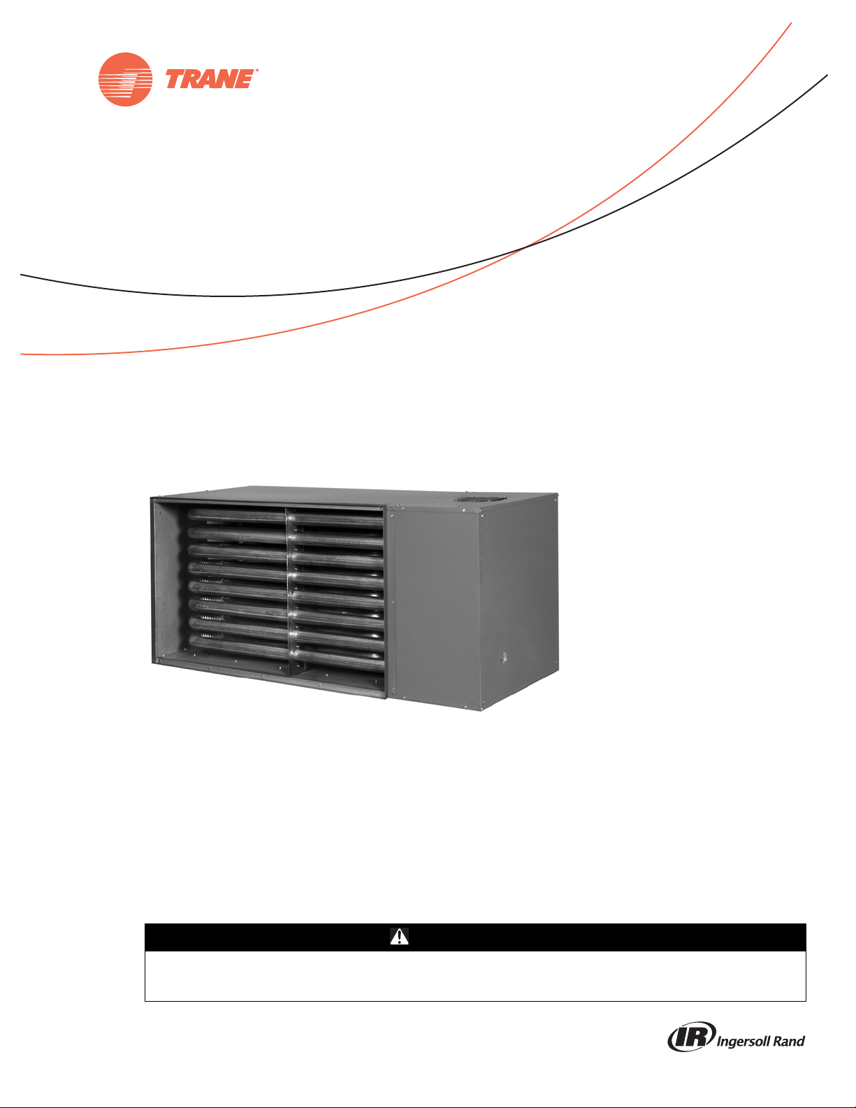
Tubular Indoor Gas Fired Duct Furnace
Model Number
GUNE
SAFETY WARNING
Only qualified personnel should install and service the equipment. The installation, starting up, and servicing of heating, ventilating, and airconditioning equipment can be hazardous and requires specific knowledge and training. Improperly installed, adjusted or altered equipment
by an unqualified person could result in death or serious injury. When working on the equipment, observe all pr ecautions in the literature and
on the tags, stickers, and labels that are attached to the equipment.
June 2014
GUNE-SVX001A-EN
J30-09453
Page 2
Introduction
Read this manual thoroughly before operating or servicing
this unit.
Warnings, Cautions, and Notices
Safety advisories appear throughout this manual as
required. Y our personal safety and the proper operation of
this machine depend upon the strict observance of these
precautions.
The three types of advisories are defined as follows:
WARNING
CAUTIONs
NOTICE:
Proper Field Wiring and Grounding
Required!
Failure to follow code could result in death or serious
injury. All field wiring MUST be performed by qualified
personnel. Improperly installed and grounded field
wiring poses FIRE and ELECTROCUTION hazards. To
avoid these hazards, y ou MUST f ollow r equir ements for
field wiring installation and grounding as described in
NEC and your local/state electrical codes.
Indicates a potentially hazardous
situation which, if not avoided, could
result in death or serious injury.
Indicates a potentially hazardous
situation which, if not avoided, could
result in minor or moderate injury. It
could also be used to alert against
unsafe practices.
Indicates a situation that could result in
equipment or property-damage only
accidents.
WARNING
WARNING
Personal Protective Equipment (PPE)
Required!
Installing/servicing this unit could result in exposure to
electrical, mechanical and chemical hazards.
• Before installing/servi cin g th is un it, technicians
MUST put on all PPE required for the work being
undertaken (Examples; cut r esistant glo v es/sleeves,
butyl gloves, saf ety glasses, hard hat/bump cap, fall
protection, electrical PPE and arc flash clothing).
ALWAYS refer to appropriate Material Safety Data
Sheets (MSDS)/Safety Data Sheets (SDS) and OSHA
guidelines for proper PPE.
• When working with or ar ound hazar dous chemi cals,
ALWAYS refer to the appropriate MSDS/SDS and
OSHA/GHS (Global Harmonized System of
Classification and Labelling of Chemicals) guidelines
for information on allowable personal exposure
levels, proper respiratory protection and handling
instructions.
• If there is a risk of ener gized electr ical contac t, arc, or
flash, technicians MUS T put on all PPE in accor dance
with OSHA, NFPA 70E, or other country-specific
requirements for arc flash protection, PRIOR to
servicing the unit. NEVER PERFORM ANY
SWITCHING, DISCONNECTING, OR VOLTAGE
TESTING WITHOUT PROPER ELECTRICAL PPE AND
ARC FLASH CLOTHING. ENSURE ELECTRICAL
METERS AND EQUIPMENT ARE PROPERLY RATED
FOR INTENDED VOLTAGE.
Failure to follow instructions could result in death or
serious injury.
© 2014 Trane All rights reserved GUNE-SVX001A-EN
Page 3
WARNING
Safety Aler t!
You MUST follow all instru ctions below. Failure to do so
could result in death or serious injury.
For Your Safety
The use and storage of gasoline or other flammable
vapors and liquids in open containers in the vicinity
of this appliance is hazardous.
If you smell gas:
1. Open windows.
2. Don’t touch electrical switches.
3. Extinguish any open flame.
4. Immediately contact your gas supplier.
WARNING
Hazardous Gases and Flammable Vapors!
Failure to observe following instructions could result in
death or serious injury. Exposure to hazardous gases
from fuel substances have been shown to cause cancer,
birth defects or other reproductive harm. Improper
installation, adjustment, alteration, service or use of
this product could cause flammable mixtures or lead to
excessive carbon mon oxide. To avoid hazardous gases
and flammable vapors follow proper installation and
set up of this product and all warnings as provided in
this manual.
Approved for Use in California
WARNING
Toxic Hazard!
Install, operate, and maintain unit in accordance with
the manufacturer’s instructions to avoid exposure to
fuel substances, or substances from incomplete
combustion, which can cause death or serious illness.
The state of California has determined that these
substances may cause cancer, birth defects, or other
reproductive harm.
Installer’s Responsibility
Installer Please Note: This equipment has been test
fired and inspected. It has been shipped free from defects
from our factory. However, shipment and installation
problems such as loose wires, leaks, and loose fasteners
may occur. It is the installer’ s responsibility to inspect and
correct any problem that may be found.
Receiving Instructions
Inspect shipment immediately when received to
determine if any damage has occurred to the unit duri ng
shipment. After the unit has been uncrated, c heck for any
visible damage to the unit. If any damage is found, the
consignee should sign the bill of lading indicating such
Introduction
damage and immediately file claim for damage with the
transportation company.
General Safety Information
WARNING
Safety Alert!
You MUST follow all instr uctions belo w. Failure to do so
could result in death or serious injury.
• The tubular duct furnace design is certified by ETL for
use with natural and propane (LP) gases. ANSI and
NFP A Standards as well as Canadian installation codes
referred to in this manual are the ones that were
applicable at the time the design was cer t if ied. In
addition, the tubular duct fur nace may be installed on
the downstream side of a cooling unit, without need of
a bypass duct.
• Installation must be made in accordance with local
codes, or in absence of local codes, with the latest
edition of the National Fuel Gas Code, ANSI
Standard Z223.1 (NFPA 54).
All of the ANSI and NFPA Standards referred to in
these installation instructions are those that wer e
applicable at the time the design of this appliance
was certified. The ANSI Standards are available from
the CSA Information Services, (800) 463-6727, as w ell
as at www.ansi.org
available fr om the National Fire Protection
Association, 1 Batterymarch Park, Quincy, MA 02169,
as well as at www.nfpa.org. These duct furnaces are
designed for use in airplane hangars when installed
in accordance with curr ent ANSI/NFP A No . 409 and in
public garages when installed in accordance with
current NFPA No. 88A and NFPA No. 88B.
If installed in Canada, the installation must conform
with local building codes, or in absence of local
building codes, with CSA-B149.1 “Installation Codes
for Natural Gas Burning Appliances and Equipment”
or CSA-B149.2 “Installati on Cod e s for Propane Gas
Burning Appliances and Equipment.” These indoor
duct furnaces have been designed and certified to
comply with CSA 2.6. Also refer to “Aircraft Hangars,”
p. 10 and “Public Garages,” p. 10.
• Do not alter the duct furnace in any w ay or damage t o
the unit and/or severe person al injury or death could
occur!
• This product must be installed by a licensed plumber
or gas fitt er when installed within the Commonw ealth
of Massachusetts.
• Turn off the gas supply and disconnect all electric
power, including remote disconnects befor e servicing
unit. Follow proper lockout/tagout procedures to
ensure the power can not be inadv e rtently energized
and the gas can not be inadve rtently tur ned on. Failur e
to turn off gas or disconnect power before servicing
could result in death or serious injury.
. The NFPA Standards are
GUNE-SVX001A-EN 3
Page 4
Introduction
• Follow installation instructions CAREFULLY to avoid
creating unsafe conditions. All wiring should be done
and checked by a qualified electrician, using copper
wire only. All external wiring must conform to
applicable local codes, and to the latest edition of the
National Electric Code
ANSI/NFPA No. 70.
• All gas connections should be made and leak-t ested by
a suitable qualified individual, per instr ucti ons in this
manual. Also follow procedures listed in “Gas
Equipment Start-Up,” p. 30.
• Use only the fuel for which the duct furnace is
designed (see rating plate). Using LP gas in a heater
that requires natur al gas, or vice v ersa, will creat e the
risk of gas leaks, carbon monoxide poisoning and
explosion.
Important: Do not attempt to convert the duct
furnace for use with a fuel other than
the one intended. Such conversion is
dangerous, as it could create the risks
listed previously.
• Use only the fuel for which the heater is designed (see
rating plate). Using LP gas in a heater that requires
natural gas, or vice versa, will create the risk of gas
leaks, carbon monoxide poisoning and explosion.
• Make certain that the power source conforms to the
electrical requirements of the heater.
• Do not depend upon a thermostat o r other swi tch as
a sole means of disconnecting pow er when installing
or servicing heater . Always disconnect pow er at main
circuit breaker as described above. Failure to do so
could result in f atal el ectric shock.
• Special attention must be giv e n to any grounding
information pertaining to this heater. To prevent the
risk of electrocution, the heater mus t be secur ely and
adequately grounded . This should be accomplished by
connecting a grounded conductor between the
service panel and the heater. To ensure a proper
ground, the grounding means must be tested by a
qualified technician.
• Do not insert fing ers or fore ign objects into the heater
or its combustion air moving device. Do not block or
tamper with the heater in any manner while in
operation or just aft er it has t ur ned of f , as some parts
may be hot enough to cause injury.
• This heater is intended for general heating
applications ONLY . It must NO T be used in pot entially
dangerous locations such as flammable, explosive,
chemical-laden or wet atmospheres.
• In cases in which property damage may result from
malfunction of the heater, a backup system or a
temperature sensitive alarm should be used.
• The open end of gas piping systems being purged shall
not be discharged int o areas where there are sources
of ignition or into confined spaces UNLESS
precautions are taken as follows: 1) by ventilation of
the space, 2) by control of purging rate, 3) by
elimination of all hazardous condi tion s. All
precautions must be tak en to perform th is operation in
a safe manner!
Unless otherwise specified, the following conversions
may be used for calculating SI unit measurements:
1 foot = 0.305 m 1 inch = 25.4 mm
1 gallon = 3.785 L 1 pound = 0.453 kg
1 psig = 6.894 kPa 1 cubic foot = 0.028m
1000 BTU per hour = 0.293 kW 1 inch water column = 0.249 kPa
1000 BTU/Cu.Ft. = 37.5 MJ/m3 Liter/second = CFM x 0.472
Meter/second = FPM ÷ 1 96.8
3
Copyright
This document and the information in it are the property of
T rane, and may not be used or reproduced in whole or in
part without written permission. Trane reserve s the right
to revise this publication at any time, and to make c hanges
to its content without obligation to notify any person of
such revision or change.
Trademarks
All trademarks referenced in this document are the
trademarks of their respective owners.
Revision History
GUNE-SVX001A-EN (16 Jun 2014)
• First versio n of this literature
4 GUNE-SVX001A-EN
Page 5

Table of Contents
Introduction . . . . . . . . . . . . . . . . . . . . . . . . . . . . . 2
Warnings, Cautions, and Notices . . . . . . . . 2
General Safety Information . . . . . . . . . . . . . 3
Copyright . . . . . . . . . . . . . . . . . . . . . . . . . . . . . 4
Model Number Description . . . . . . . . . . . . . . . 6
General Information . . . . . . . . . . . . . . . . . . . . . 7
Dimensional Data and Weights . . . . . . . . . . . 8
Performance Data . . . . . . . . . . . . . . . . . . . . . . . 9
Installation . . . . . . . . . . . . . . . . . . . . . . . . . . . . . 10
Locating Units . . . . . . . . . . . . . . . . . . . . . . . . 10
Clearances . . . . . . . . . . . . . . . . . . . . . . . . . . . 10
Accessibility Clearance . . . . . . . . . . . . . . 10
Atmospheric Considerations . . . . . . . . . . 10
Aircraft Hangars . . . . . . . . . . . . . . . . . . . . 10
Public Garages . . . . . . . . . . . . . . . . . . . . . 10
Ductwork . . . . . . . . . . . . . . . . . . . . . . . . . . 11
Air Flow . . . . . . . . . . . . . . . . . . . . . . . . . . . 11
Combustion Inlet Air Ventilation . . . . . . . 11
Bypass . . . . . . . . . . . . . . . . . . . . . . . . . . . . 11
Suspension . . . . . . . . . . . . . . . . . . . . . . . . 12
Conversion of access side . . . . . . . . . . . . 12
Gas Pipe Sizing . . . . . . . . . . . . . . . . . . . . . 13
Pipe Sizing . . . . . . . . . . . . . . . . . . . . . . . . 13
Pipe Installation . . . . . . . . . . . . . . . . . . . . 14
Venting . . . . . . . . . . . . . . . . . . . . . . . . . . . . . . 16
Venting for Power Vented Duct Furnaces
(Category III) . . . . . . . . . . . . . . . . . . . . . . . 16
Vertically Vented Duct Furnaces (Category III)
. . . . . . . . . . . . . . . . . . . . . . . . . . . . . . . . . . 17
Horizontally Vented Duct Furnaces
(Category III) . . . . . . . . . . . . . . . . . . . . . . . 17
Combustion Air . . . . . . . . . . . . . . . . . . . . 20
Exhaust Venting . . . . . . . . . . . . . . . . . . . . 21
Shut Down . . . . . . . . . . . . . . . . . . . . . . . . .27
Gas Input Rate . . . . . . . . . . . . . . . . . . . . . .28
Tubular Duct Furnace—High Altitude Dera-
tion . . . . . . . . . . . . . . . . . . . . . . . . . . . . . . .29
Gas Equipment Start-Up . . . . . . . . . . . . . . . . .30
Maintenance . . . . . . . . . . . . . . . . . . . . . . . . . . . .31
Periodic Service . . . . . . . . . . . . . . . . . . . . . . .31
Identification of Parts Tubular Duct Furnace
. . . . . . . . . . . . . . . . . . . . . . . . . . . . . . . . . . . . . .32
How To Order Replacement Parts . . . . . . . .33
Troubleshooting . . . . . . . . . . . . . . . . . . . . . . . . .34
Warranty . . . . . . . . . . . . . . . . . . . . . . . . . . . . . . .38
Electrical Connections . . . . . . . . . . . . . . . . . . . 25
Thermostat Wiring and Location . . . . . . 25
Operation . . . . . . . . . . . . . . . . . . . . . . . . . . . . . . 27
Tubular Duct Furnace Direct Spark Ignition 27
Explanation of Controls . . . . . . . . . . . . . . 27
Start-Up . . . . . . . . . . . . . . . . . . . . . . . . . . . 27
GUNE-SVX001A-EN 5
Page 6

Model Number Description
12345678910111213141516
GUNE020AHA10000B
Digit 1 — Gas Heating
Equipment
G = Gas Heating Equipment
Digit 2 — Product Type
U = Tubular Duct Furnace
Digit 3 — Fuel Type
N=Natural Gas
P = Propane Gas (LP)
Digit 4 — Developmental
Sequence
E = Current Developmental
Sequence
Digits 5, 6, 7 — Input Capacity
(MBh)
010 = 100
015 = 150
020= 200
025= 250
030= 300
035= 350
040= 400
Digit 8 — Main Power Supply
A = 115/60/1
B = 230/60/1
C = 208/60/3
D = 230/60/3
E = 460/60/3
F = 575/60/3
G = 208/60/1
Digit 9 — Gas Control Option
H = Electronic Modulating w/Room
Sensing
J = Electronic Modulating w/Duct
Thermostat
L = Electronic Modulation
w/External 4–20 mA Input
M = Electronic Modulation
w/External 0–10 Vdc Input
T = Single-Stage, Direct Spark
Ignition
V = Two-Stage, Direct Spark Ignition
W = Electronic Modulation w/Duct
Thermostat/Room Override Stat
Digit 10 — Design Sequence
A=First Design
Digit 11 — Heat Exchanger
Material
1 = Standard (Aluminized Steel)
2 = 409 Stainless Steel
Digit 12, 13, 14 — Reserved for
Future Use
0=Not Used
Digit 15 — Miscellaneous
0=None
B = Air Pressure Switch for Above
5,000 Feet
G = Horizontal and Vertical Louvers
W = Stainless Steel Drain Pan
6 GUNE-SVX001A-EN
Page 7
General Information
Important: It is the equipment owners responsibility to
provide any scaffolding or other apparatus
required to perform emergency service or
annual/periodic maintenance to this
equipment
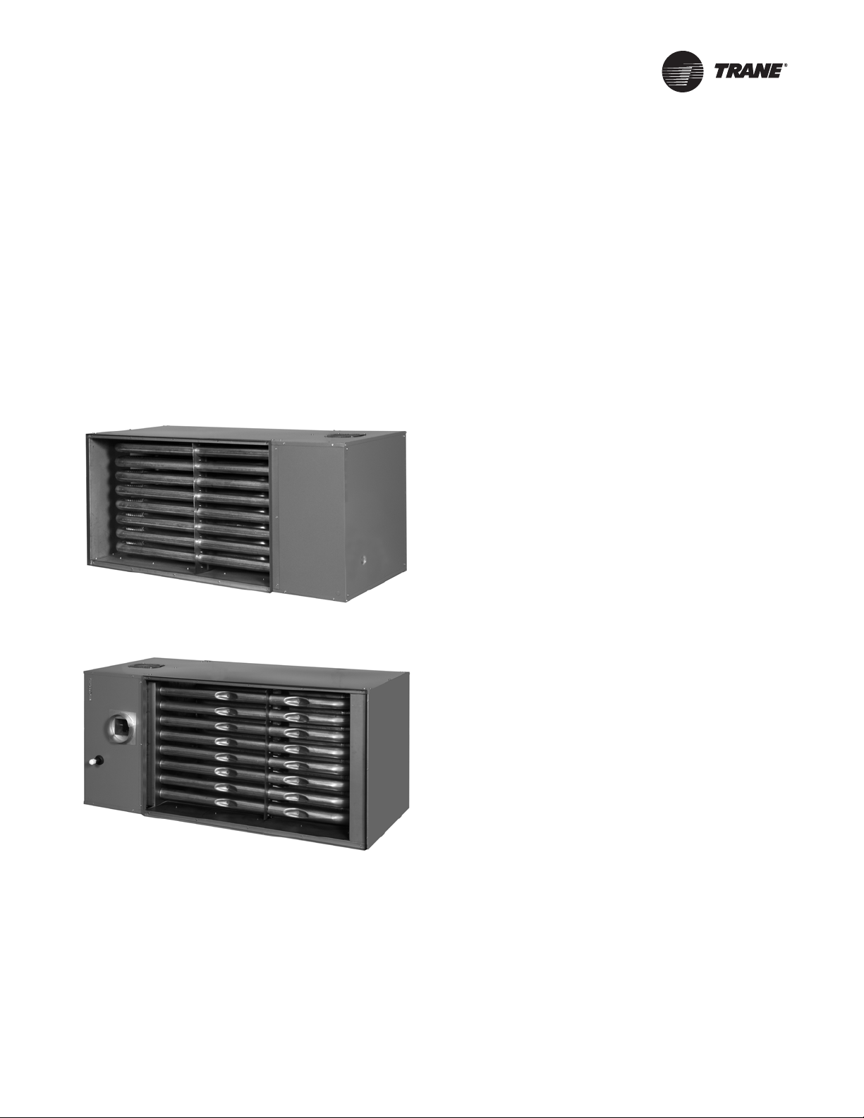
The Tubular Indoor Gas-Fired Duct Furnace is a factory
assembled, power vented, and low static pressure type
duct furnace with a low profile cabinet. The duct furnace
can also be easily field converted to separated
combustion. The design is certified by ETL as providing a
minimum of 82 percent thermal efficiency, and approved
for use in California. Do not alter these units in any w ay . If
you have any questions after reading this manual, contact
the manufacturer.
Figure 1. Front
Figure 2. Back
GUNE-SVX001A-EN 7
Page 8
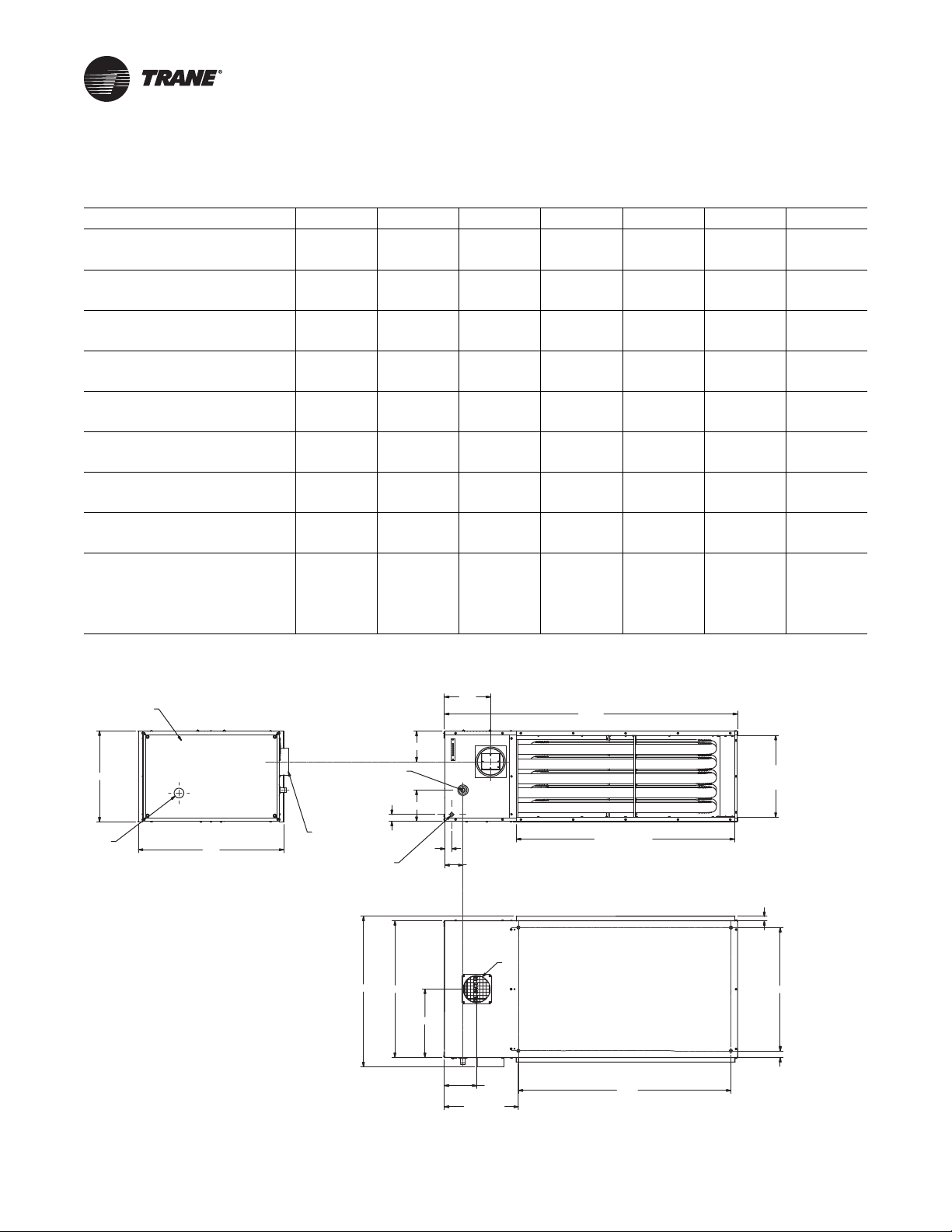
Dimensional Data and Weights
Table 1. Dimensional data and weights—tubular duct furnace dimensions, inches (mm)
Unit Capacity 100 150 200 250 300 350 400
“A” Overall Unit Height
“B” Height to Centerline Flue
“C” Height to Gas Connection
“D” Opening Height, Front & Rear
“E” Overall Unit Depth
“F” Flue Size Diameter
“G” Air Inlet Size Diameter
Gas Inlet, Natural Gas, inches 1/2 1/2 1/2 3/4 3/4 3/4 3/4
Gas Inlet, Natural Gas, inches 1/2 1/2 1/2 3/4 3/4 3/4 3/4
Approximate Unit Weight, lb (kg)
Approximate Ship Weight, lb (kg)
10.3 13.7 17 20.2 23.5 26.7 30
(262) (348) (432) (513) (597) (678) (762)
7.6 10.5 11.9 6.8 8.4 10 11.6
(193) (267) (302) (173) (213) (254) (295)
2.5 3.7 5.3 7 7 8.7 10.3
(64) (94) (135) (178) (178) (221) (262)
8.5 11.7 15 18.2 21.5 24.7 28
(216) (297) (381) (462) (546) (627) (711)
32.7 32.7 32.7 33.5 33.5 33.5 33.5
(831) (831) (831) (851) (851) (851) (851)
5556666
(127) (127) (127) (152) (152) (152) (152)
5556666
(127) (127) (127) (152) (152) (152) (152)
160 221 250 270 296 321 355
(73) (100) (113) (122) (134) (146) (161)
270 331 360 403 429 454 488
(122) (150) (163) (183) (195) (206) (221)
Figure 3. Tubular duct furnace dimensions
ACCESS PANEL
A
PEEP
HOLE
32.5
SIDE VIEW
D9362
F
CONNECTION
POWER
CONNECTION
E
GAS
1.5
30.500
B
C
1.5
15.251
10.3
4
16.5
HANGING
LOCATION
7.197
65.500
D
OPENING
FRONT & REAR
48.7
OPENING
FRONT & REAR
REAR VIEW
1.000
G
27.50
1.50
47.50
TOP VIEW
8 GUNE-SVX001A-EN
Page 9
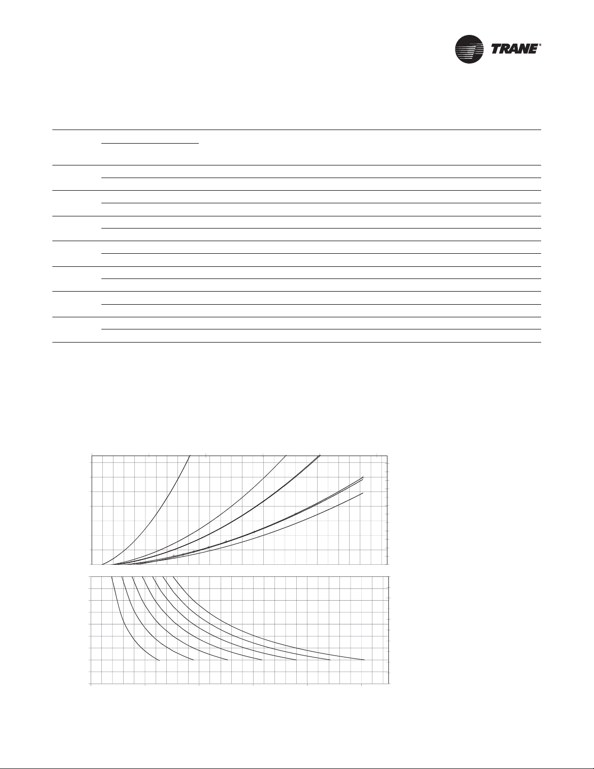
Performance Data
Size 200
Size 250
Size 300
Size 350
Size 400
Size 150
Size 100
0
25
50
75
100
125
150
175
200
225
250
275
300
012345
0
0.2
0.4
0.6
0.8
1
1.2
1.4
Pa
m3/s
Pressure Drop, inches W.C.
Size 150 Size 200 Size 250 Size 300 Size 350 Size 400
Size 100
6
11
16
21
26
31
36
41
46
51
56
10
20
30
40
50
60
70
80
90
100
0 2000 4000 6000 8000 10000
°C
Temperature Rise, °F
Airflow (CFM )
Table 2. Tubular duct furnace performance data
Input
Unit Size
100
150
200
250
300
350
400
Notes:
1. Ratings are shown for unit installations at elevations between 0 and 2,000 feet (610m).
2. For unit installations in U.S.A. above 2,000 feet (610 m), the unit input must be field der a te d 4 percent for each 1,000 feet (305 m) above sea level;
refer to local codes, or in absence of local codes, refer to the latest edition of the National Fuel Gas Code, ANSI Standard Z223.1 (NFPA 54).
3. For installations in Canada, any references to deration at altitudes in excess of 2,000 feet (610 m) are to be ignored. At altitudes of 2,000 to
4,500 feet (610 to 1372 m), the unit must be field derated and be so marked in accordance with the ETL certification.
4. See Tab le 10 and Table 11, p. 29 for U.S.A. and Canadian field deration information.
(kW)
100 50 82 758 100 0.07 2528 30 0.65
(29.3) (14.6) (24.0) (0.357) (56) (0.017) (1.193) (17) (0.16)
150 75 123 1137 100 0.03 3792 30 0.44
(43.9) (21.9) (36.0) (0.536) (56) (0.007) (1.789) (17) (0.11)
200 100 164 1517 100 0.04 5057 30 0.54
(58.6) (29.3) (48.0) (0.715) (56) (0.009) (2.386) (17) (0.13)
250 125 205 1896 100 0.08 6321 30 0.76
(73.2) (36.6) (60.0) (0.894) (56) (0.019) (2.983) (17) (0.19)
300 150 246 2275 100 0.03 7585 30 0.69
(87.8) (43.9) (72.0) (1.074) (56) (0.007) (3.579) (17) (0.16)
350 175 287 2654 100 0.07 8849 30 0.76
(102.5) (51.2) (84.1) (1.252) (56) (0.017) (4.176) (17) (0.19)
400 200 328 3034 100 0.08 10,114 30 0.70
(117.1) (58.6) (96.1) (1.431) (56) (0.019) (4.773) (17) (0.17)
(Max) MBh
(Min) MBh
(kW)
Output
MBh (kW)
Min CFM
(m3/s)
Temp rise
°F (°C)
P.D. in. wc
(kPa)
Max CFM
(m3/s)
Temp rise
°F (°C)
P.D. in. wc
(kPa)
Figure 4. Temperature rise and pressure drop graph
GUNE-SVX001A-EN 9
Page 10
Installation
Locating Units
NOTICE:
Equipment Damage!
Do not install unit heaters in corrosive of flammable
atmospheres! Pr ematur e f ailure of , or sever e damage t o
the unit will result!
NOTICE:
Equipment Damage!
Avoid locations where extreme drafts can affect burner
operation. Duct furnaces mus t not be installed in
locations where air for combustion would contain
chlorinated, halogenated or acidic vapors. If located in
such an environment, premature failure of the unit will
occur!
Important: Location of unit heaters is related directly to
the selection of sizes. Basic rules are as
follows,
Clearances
WARNING
Combustible Materials!
Failure to mainta in proper clearance between the unit
heat exchanger, vent surfaces and combustible
materials could cause a fire which could result in death
or serious injury or property damage. Refer to Table 3
for proper clearances.
Maintain adequate clearances around air openings into
the combustion chamber:
Table 3. Minimum safety clearances
Sides 6 inches (152 millimeters)
Top 6 inches (152 millimeters)
Bottom 6 inches (152 millimeters)
Flue 6 inches (152 millimeters)
(a) When clearances required for accessibility are greater than the mini-
mum safety clearances, the accessibility clearances take precedence.
Accessibility Clearance
The duct furnace must have 18 inches (457 mm) clearance
on the control cabinet end. Provision should also be made
to assure accessibility for recurrent maintenance
purposes.
Atmospheric Considerations
Atmospheres containing commercial solvents or
chlorinated hydrocarbons will produce corrosive acids
(a)
when coming in contact with the flames. This will greatly
reduce the life of the gas duct furnace and may void the
warranty. Avoid such areas.
Important: If the gas duct furnace is to be used in a
building classified as having a hazardous
atmosphere, the installation must comply
with the standards set by the National
Board of Fire Underwriters. Consult the
authorities having jurisdiction before
starting the job.
The duct furnace must be installed on the positive
pressure side of the air circulation blower.
Airc raft Hangars
In aircraft hangars, duct furnaces must be at least 10 feet
(3.05 m) above the upper surface of wings or engine
enclosures of the highest aircraft to be stored in the hangar
and 8 feet (2.4 m) above the floor in shops, offices, and
other sections of the hangar where aircraft are not stored
and housed. Refer to cur rent ANSI/NFPA No. 409, Aircraft
Hangars. In Canada, installation is suitable in aircraft
hangars when acceptable to the enforcing authorities.
Public Garages
In repair garages, duct furnaces must be installed in a
detached buildin g or room separated from repair areas as
specified in the latest edition of NFP A 88B, Repair Garages.
In parking structures, duct furnaces must be installed so
that the burner flames are located a minimum of 18 inches
(457 mm) above the floor or protected by a partition not
less than 18 inches (457 mm) high. Refer to the latest
edition of NFPA 88A, Parking Structures.
In Canada, installation must be in accordance with the
latest edition of CSA B149 “Installation Codes for Gas
Burning Appliances and Equipment.”
Important:
• The duct furnace must be installed such that the gas
ignition control system is not directly exposed to water
spray, rain, or dripping water.
• Duct furnaces should not be installed to maintain low
temperatures and/or freeze protection of buildings. A
minimum of 50°F (10°C) thermostat setting must be
maintained.
If duct furnaces are operated to maintain lower than 50°F
(10°C), hot flue gases are cooled inside the heat exc hanger
to the point where water vapor (a flue gas by-product)
condenses onto the heat exchanger walls. The result is a
mildly corrosive acid that prematurely corr odes the
aluminized steel heat exchanger and can actually drip
water down from the duct furnace onto the floor surface
below. Additional duct furnaces should be installed if a
minimum 50°F (10°C) thermostat setting cannot be
maintained.
10 GUNE-SVX001A-EN
Page 11
Installation
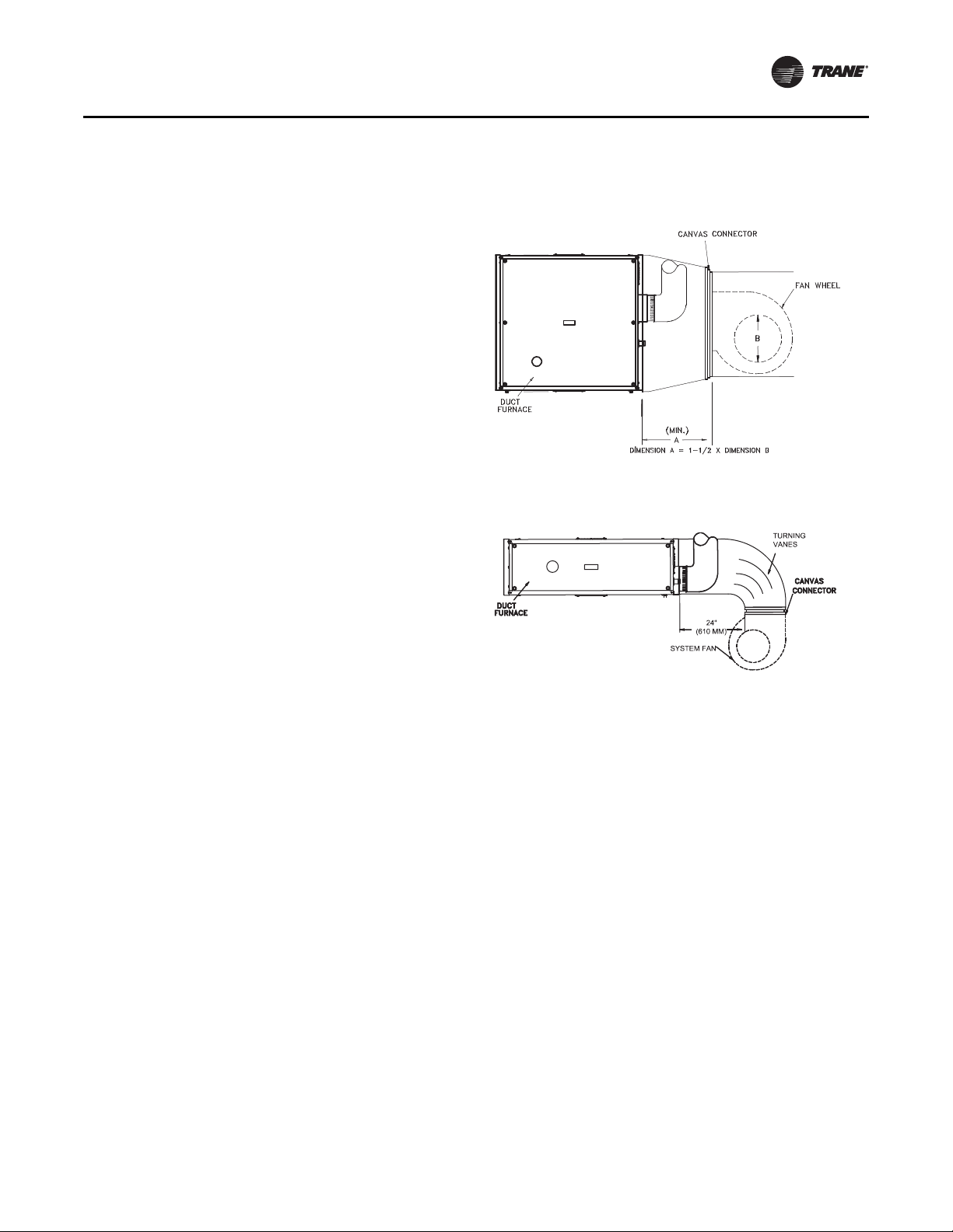
Ductwork
Properly designed and installed ductwork, providing a
uniformly distributed flow of air across all surfaces of the
heat exchanger, is essential to satisfactory unit
performance and life of the equipment.
All duct connection flanges/seams must be sealed to
prevent air leaks. Sealant/tape must be suitable for
temperatures of 250°F (121°C) minimum.
Note: Any attempts to straighten the 90° duct connection
flanges on the duct furnaces will affect the
operation of the furnace and will void the warranty .
If uniform air distribution is not obtained, install additional
baffles and/or turning vanes in the ductwork.
Figure 5 and Figure 6 illustrate recommended ductwork
designs for both the straight-through and elbowed air i nlet
arrangements.
Access panels large enough to observe smoke and
reflected light, and to detect the presence of leaks in the
heating equipment, are required both upstream and
downstream from gas duct furnaces. These panels must
be sealed to prevent air leaks. If allowed by local
regulations, install canvas connectors between the
ductwork and fan discharge opening to eliminate the
transmission of mechanical vibration.
bypass around the gas duct furnace to bypass a po rtion of
the air.
Figure 5. Recommended ductwork design for straight-
through arrangement
Figure 6. Recommended ductwor k design for elbow ed
arrangement
Air Flow
The installation is to be adjusted to obtain an air
throughput within the range specified on the appliance
rating plate.
Combustion Inlet Air Ventilation
Inlet Air From Another Room
If the duct furnace is installed in a separate room or
compartment, provide two inlet air openings. The size of
each vent opening should be no less than one square inch
(6.452 square centimeters) of free area for each
1000 Btu/h (293 W) input. Each opening must not be less
than 100 square inches (645 square centimeters).
Inlet Air From Outdoors
If the enclosed space is to have inlet combustion air from
the outside, the vent opening should be no less than one
square inch (6.452 square centimeters) of free area for
each 2500–3000 Btu/h (733–879 W) input. Each opening
must not be less than 100 square inches (645 square
centimeters).
Bypass
When a gas duct furnace is installed to operate in
conjunction with a summer air conditioning system, the
CFM air delivery of the system blower should be adjusted
to meet the design air volume requirements for co oling. If
this CFM delivery is greater than that required for heating,
resulting in a low air temperature rise, install a damper
GUNE-SVX001A-EN 11
Page 12
Installation
SECTION A-A
SCALE 1:1
A
A
D9376
A
I
R
F
L
O
W
←
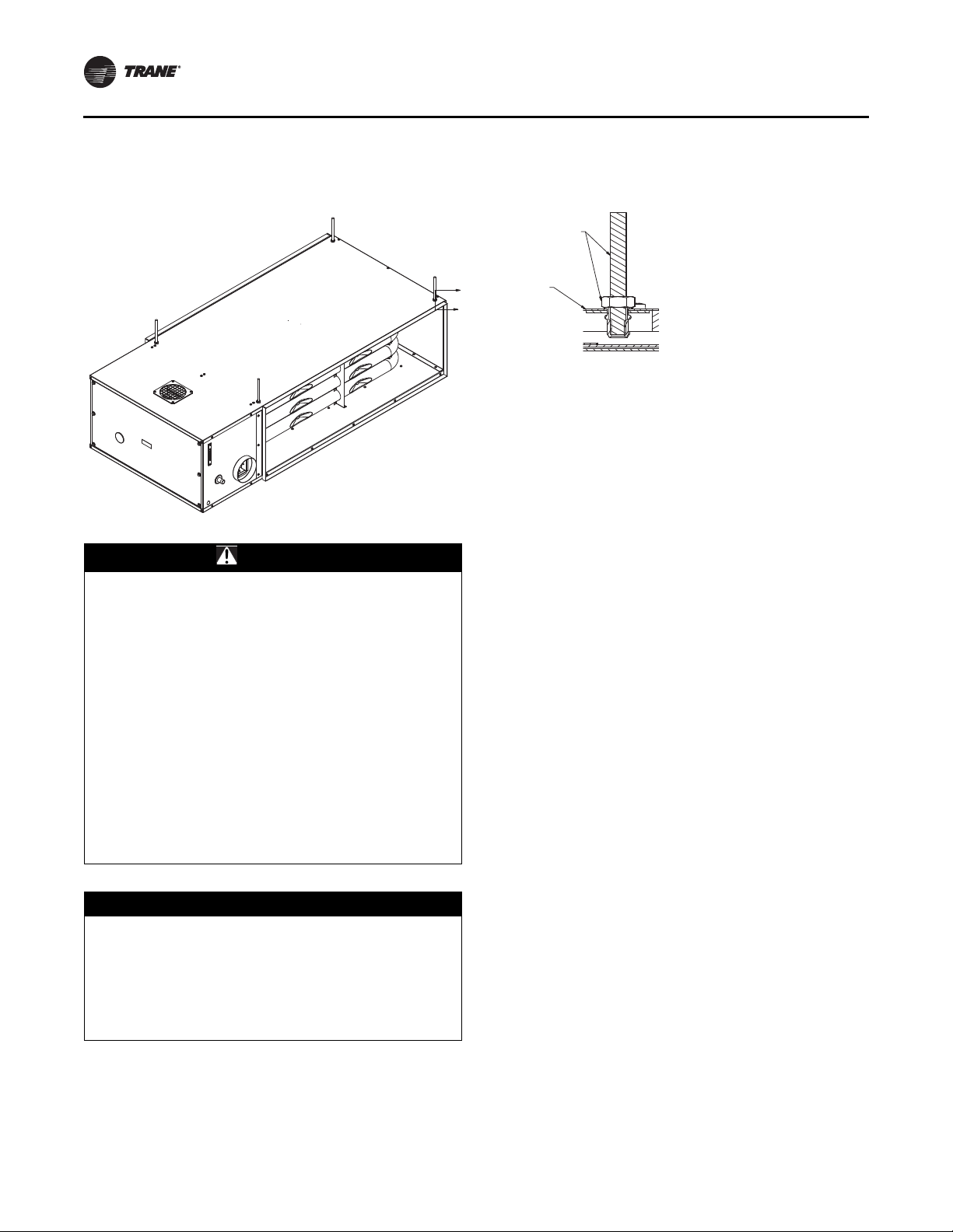
3/8" THREADED SUSPENSION ROD
& JAM NUT BY INSTALLER
OUTSIDE JACKET
PANEL (UNIT)
Suspension
Figure 7. Typical suspension
Conversion of access side
WARNING
Heavy Object!
Make certain that the lifting methods used to lift the
duct furnace are capable of supporting the weight of
the heater during installation. See Table 1, p . 8 for unit
weights.
Ensure that all hardware used in the suspension of each
duct furnace is more than adequate for the job.
Make certain that the structure to which the duct
furnace is to be mounted is capable of safely supporting
its weight. Under no circumstances must the gas lines,
venting system, or the electrical conduit be used to
support the duct furnace. Do not allow objects (i.e.
ladder) or people to lean against the gas lines, venting
system, or electrical conduit for support.
Failure to follow these instructions could result in
death, serious injury, and property damage.
NOTICE:
Equipment Damage!
The duct furnace must be hung level from side to side
and front to back, from f our suspension points provided
at the top of the unit. Failur e t o do so will r e sult in poor
performance and/or premature failure of the unit. Refer
to Figure 7 for typical suspension. DO NOT mount duct
furnaces in series (one in front of another).
Important: Minimum safety clearances must also be
maintained; see Table 3, p. 10. When
service/accessibility clearances are greater
than minimum safety clearances, service/
accessibility clearances take precedence.
Refer to “Clearances,” p. 10.
12 GUNE-SVX001A-EN
The tubular duct furnace is built and shipped as right side
access—when looking in the direction of airflow, g as and
flue connections, control cabinet access are on the right
hand side and the combustion air inlet is on top. When
looking in the direction of airflow, you will be facing the
entering air side of the duct furnace. T o conver t the unit to
left side access:
1. Before suspending unit, flip the duct furnace 180°
width-wise (not rotated) so the gas and flue
connections are still on the entering air side of the duct
furnace.
2. Remove the four (4) screws holding the combustion air
inlet screen (now located on the bottom of the unit); the
screen and gasket can be removed and set aside.
3. Remove the four (4) screws holding the block-off plate
(now located on the top of the unit); the plate and the
gasket can be removed and set aside.
4. Reinstall the block-off plate and its gasket on the
bottom of the unit using the four (4) screws.
5. Reinstall the combustion air inlet screen and its g asket
on the top of the unit using the four (4) screws.
It is not required to switc h the combustion air inlet screen
and block-off plate locations once the unit has been
flipped. However, due to combustion noise, it is
recommended to keep the air inlet screen on top for
overhead installations.
Important: If unit access side is converted, ensure
accessibility clearance is taken into account
for the new control cabinet end of the unit
before suspension/installation.
Page 13

Installation
Gas Pipe Sizing
WARNING
Fire Hazard!
Do not connect gas piping to this unit until a supply
line pressure/leak test has been completed. Connecting
the unit before completing the pressure/leak test may
damage the unit gas valve and result in a fire hazard,
which could resul t in death, ser ious injury, and property
damage.
NOTICE:
Equipment Damage!
Do not rely on a shut-off valve to isolate the unit while
conducting gas pressur e/leak tests. These valves may
not be completely shut off, exposing the gas valve to
excessive pressure and damage.
Pipe Sizing
To provide adequate gas pressure to the gas unit heater,
size the gas piping as follows:
3
1. Find the ft
/h by using the following formula:
ft3/h =
Input BTU/h/1000
1,000
Before any connection is made to the existing line
supplying other gas appliances, contact the local gas
company to make sure that the existing line is of adequate
size to handle the combined load.
2. Refer to Table 4, p. 14. Match “Length of Pipe in Feet”
3
with appropriate “Gas Input - ft
/h” value. This value
can then be matched to the pipe size at the top of the
column.
Example:
It is determined that a 67-foot (20.4-m) run of gas pipe
is required to connect a 200 MBtu gas unit heater to a
3
1,000 Btu/ft
(0.29 kW) natural gas supply.
200,000 BTU/h
1,000 BTU/ft
3
= 200 ft
3
/h
Using Table 4, a 1-inch pipe is needed.
Note: Refer to “General Safety Information,” p. 3 for
English/Metric unit conversion factors.
Important:
• If more than one unit heater is to be served by the same
3
piping arrangement, the total ft
/h input and length of
pipe must be considered.
• If the gas unit heater is to be fired with LP gas, consult
your local LP gas dealer for pipe size information.
• Heater installation for use with propane (bottled) gas
must be made by a qualified LP gas dealer or installer.
He/She will ensure that proper joint compounds are
used for making pipe connections, that air is purged
from lines, that a thorough test is made for leaks before
operating the heater, and that it is properly connected
to the propane gas supply system.
GUNE-SVX001A-EN 13
Page 14

Installation
Table 4. Gas pipe size
Nominal
Iron
Pipe
Size (in)
1/2 0.622
3/4 0.824
1-1/4 1.380
1-1/2 1.610
2-1/2 2.469
Notes:
1. Determine the required ft
2. For natural gas: select pipe size directly from the table.
3. For propane gas: multiply the ft
(a) Maximum capacity of pipe in ft
Internal
Diameter
(in)
1 1.049
2 2.067
3 3.068
4 4.026
For SI/metric measurements: convert Btu/h to kW. Multiply the unit’s inputs (kW) by 0.0965 to determine m
Refer to the metric conversion factors listed in “General Safety Information,” p. 3 for SI Unit measurement conversions.
a 0.60 specific gravity gas.
(a)
Length of Pipe, feet (meters)
10 20 30 40 50 60 70 80 90 100 125 150 175 200
(3.0) (6.1) (9.1) (12.2) (15.2) (18.3) (21.3) (24.4) (27.4) (30.5) (38.1) (45.7) (53.3) (61.0)
175 120 97 82 73 66 61 57 53 50 44 40 37 35
(4.96) (3.40) (2.75) (2.32) (2.07) (1.87) (1.73) (1.61) (1.50) (1.42) (1.25) (1.13) (1.05) (0.99)
360 250 200 170 151 138 125 118 110 103 93 84 77 72
(10.2) (7.08) (5.66) (4.81) (4.28) (3.91) (3.54) (3.34) (3.11) (2.92) (2.63) (2.38) (2.18) (2.04)
680 465 375 320 285 260 240 220 205 195 175 160 145 135
(19.3) (13.2) (10.6) (9.06) (8.07) (7.36) (6.80) (6.23) (5.80) (5.52) (4.96) (4.53) (4.11) (3.82)
1400 950 770 660 580 530 490 460 430 400 360 325 300 280
(39.6) (26.9) (21.8) (18.7) (16.4) (15.0) (13.9) (13.0) (12.2) (11.3) (10.2) (9.20) (8.50) (7.93)
2100 1460 1180 990 900 810 750 690 650 620 550 500 460 430
(59.5) (41.3) (33.4) (28.0) (25.5) (22.9) (21.2) (19.5) (18.4) (17.6) (15.6) (14.2) (13.0) (12.2)
3950 2750 2200 1900 1680 1520 1400 1300 1220 1150 1020 950 850 800
(112) (77.9) (62.3) (53.8) (47.6) (43.0) (39.6) (36.8) (34.5) (32.6) (28.9) (26.9) (24.1) (22.7)
6300 4350 3520 3000 2650 2400 2250 2050 1950 1850 1650 1500 1370 128 0
(178) (123) (99.7) (85.0) (75.0) (68.0) (63.7) (58.0) (55.2) (52.4) (46.7) (42.5) (38.8) (36.2)
11000 7700 6250 5300 4750 4300 3900 3700 3450 3250 2950 2650 2450 228 0
(311) (218) (177) (150) (135) (122) (110) (105) (97.7) (92.0) (83.5) (75.0) (69.4) (64.6)
23000 15800 12800 10900 9700 8800 8100 7500 7200 6700 6000 5500 5000 4600
(651) (447) (362) (309) (275) (249) (229) (212) (204) (190) (170 ) (156) (142) (130)
3
/h by dividing the input by 1,000.
3
/h value by 0.633; then, use the table.
3
/h of gas (m3/h) for gas pressure s of 0.5 psig (3.5 kPa) or less, and a pres sure drop o f 0.5 in. wc (124.4 Pa), based on
3
/h.
Pipe Installation
1. Install the gas piping in accordance with applicable
local codes.
2. Check gas supply pressure. Eac h duct furnace must be
connected to a manifold pressure and a gas supply
capable of supplying its full rated capacity as specified
in Table 4. A field LP tank regula tor must be used to
limit the supply pressure to a maximum of 14 inches
wc (3.5 kPa). All piping should be sized in accordance
with the latest edition of ANSI Standard Z223.1
(NFPA 54), National Fuel Gas Code; in Canada,
according to CSA B149. See Table 1, p. 8 and Table 4
for correct gas piping size. If gas pressure is excessive
on natural gas applications, install a pressure
regulating valve in the line upstream from the main
shutoff valve.
3. Adequately support the piping to prevent strain on the
gas manifold and controls.
4. To prevent the mixing of moisture with gas, run the
a. Manual “A” valve
b. Manual “B” valve
c. Solenoid valve
d. Pressure regulator
Pipe directly into the combination valve (see Figure 8,
p. 15).
6. Gas valve has a pressure test post requiring a 3/32-inch
hex head wrench to read g as supply and manifold
pressures. Open 1/4 turn counterclockwise to read,
turn clockwise to close and re-seat. A 5/16-inc h ID hose
fits the pressure post.
7. Provide a drip leg in the gas piping near the gas duct
furnace. A ground joint union and a manual g as shutoff
valve should be installed ahead of the unit heater
controls to permit servicing. The manual shutoff valve
must be located external to the jacket (see Figure 8).
8. Make certain that all connections have been
adequately doped and tightened.
take-off piping from the top, or side, of the main.
5. Standard duct furnaces, optional two-stage and
modulation units are supplied with a combination
valve which includes:
14 GUNE-SVX001A-EN
Page 15

Installation
WARNING
Hazard of Explosion!
Failure to follow proper safe leak test procedures could
result in death or serious injury or equipment or
property-only-damage. NEVER use an open flame to
detect gas leaks. You MUST use a leak test solution for
leak testing.
NOTICE:
Valve Damage!
Do not over tighten the inlet gas piping into the valve.
This may cause stresses that will crack the valve!
Important: Use pipe joint sealant resistant to the action
of liquefied petroleum gases regardless of
gas connected.
Figure 8. Pipe installation, standard controls
Table 5. Gas supply pressure
Heating Value
Manifold Pressure
Single Stage Application
Two Stage Application High Fire
Two Stage Application Low Fire
Modulating Application High Fire
Modulating Application Low Fire
Minimum Supply Pressure
Single Stage Application
Two Stage Application
Modulating Application
Maximum Pressure
Note: Refer to “Tubular Duct Furnace—High Altitude Deration,” p. 29for
altitudes greater than 2,000 feet (610 m).
(a)Applicable for units installed at or below 2,000 feet (610 m) altitude.
(inch wc) 3.5 10.0
(inch wc) 3.5 10.0
(inch wc) 1.1 3.8
(inch wc) 3.5 10.0
(inch wc) 0.9 3.5
(inch wc) 5.0 11.0
(inch wc) 6.5 11.5
(inch wc) 6.5 11.5
(inch wc) 14.0 14.0
(a)
Natural Gas Propane Gas
1,050 BTU/Ft3
(39.1 MJ/m
(kPa) (0.87) (2.49)
(kPa) (0.87) (2.49)
(kPa) (0.27) (0.95)
(kPa) (0.87) (2.49)
(kPa) (0.22) (0.87)
(kPa) (1.24) (2.74)
(kPa) (1.62) (2.86)
(kPa) (1.62) (2.86)
(kPa) (3.49) (3.49)
2,500 BTU/Ft
3
(93.1 MJ/m
)
3
3
)
The appliance and its individual shutoff valve must be
disconnected from the gas supply piping system during
any pressure testing of that system in excess of 1/2 psig
(3.5 kPa).
The appliance must be isolated from the gas supply piping
system by closing its individual manual shutoff valve
during any pressure testing of the gas supply piping
system at test pressures equal to or less than 1/2 psig
(3.5 kPa).
GUNE-SVX001A-EN 15
Page 16

Installation
Venting
Note: All vertical and horizontal venting arrangements
for Tubular Duct Furnaces are Category III venting.
ANSI now organizes vented appliances into four
categories.
Table 6. Venting categories
Non-Condensing Condensing
Negative Vent
Pressure
Positive Vent
Pressure
Category I. Includes non-condensing appliances with
negative vent pressure, like the traditional atmospheric
unit heater.
Category II. Groups condensing appliances with
negative vent pressure.
Category III. Ap pliances are non-condensing and
operate with a positive vent pressure.
Category IV. Covers condensing appliances with
positive vent pressure.
Venting for Power Vented Duct Furnaces (Category III)
Carbon Monoxide Poisoning!
Your venting system must not be blocke d by any snow,
snow drifts, or any foreign matter. Inspect your venting
system to ensure adequate ventilation exists at all
time! Failur e t o f ollo w these instructions could result in
Carbon Monoxide Poisoning (symptoms include
grogginess, lethargy , inappropriate tiredness, or flu-like
symptoms) which could result in death or serious
injury.
Combustible Materials!
Failure to maintain proper clearance between the vent
pipe and combustible materials could cause a fire
which could resu lt in death or ser ious injury or pr operty
damage. Refer to Table 3, p. 10 for proper clearances.
Important: All duct furnaces must be vented!
All venting installations shall be in accordance with the
latest edition of Part 7, Venting of Equipment of the
National Fuel Gas Code, ANSI Z223.1, or applicable
provisions of local building codes for power vented units.
Refer to Figure 9, p. 19 through Figure 17, p. 24. For
installations in Canada, see “Additional Requirement for
Canadian Installations,” p. 17.
III
III IV
WARNING
WARNING
Do not damper or add heat recovery devices to the flue
piping. Failure to open such a damper prior to operating
gas unit will result in the spillage of flue gas into the
occupied space.
Vent pipe material must be in compliance with UL 1738 for
installations in the United States, and ULS636 for
installations in Canada. Refer to Table 7 for vent
termination clearance requirements.
Through the wall vents for these appliances shall NOT
terminate over public walkways, or over an area where
condensate or vapor could create a nuisance or hazard or
could be detrimental to the operation of regulators, relief
valves, or other equipment.
The vent pipe equivalent length must be 5 feet (1.5 m)
minimum and must not exceed 50 feet (15.2 m).
Equivalent length is the total length of straight sections
PLUS 10 feet (3.05 m) for each 90° elbow, and 4 feet
(1.22 m) for each 45° elbow.
Maintain 6 inches (152 mm) between vent pipe and
combustible materials. A minimum of 12 inches (305 mm)
of straight pipe is required from the venter outlet before
installing an elbow in the vent system. An elbow should
never be attached directly to the venter!
WARNING
Proper Vent Pipe Required!
Never use a pipe of a diameter other than that specified
inTable 1, p. 8! Never use PVC or other non-metallic
pipe for venting! Failure to follow instructions could
result in death, serious injury, and property damage.
Any run of single wall vent pipe exposed to cold air or
passing through an unheated space must be insulated
with insulation suitable to 550°F (288°C).
The vent system must be installed to prevent collection of
condensate. Ve rtical vent pipes should be equipped with
condensate drains. Pitch horizontal pipes downward
1/4 inches per foot (2 mm/m) toward outlet for condensate
drainage.
Horizontal portions of the venting system shall be
supported at maximum intervals of 4 feet (1.2m) to
prevent sagging. In Canada, support at a maximum of
3 feet (1 m) intervals.
WARNING
Carbon Monoxide!
Never operate duct furnaces without combustion air
and flue gas piping in place. Each unit MUST have an
individual vent pipe and vent terminal per furnace
section! Each unit MUST NOT be connected to other
vent systems or to a chimney. Your venting system
must not be blocked by any snow, snow drifts, or any
foreign matter. Inspect your venting system to ensure
adequate ventilation exists at all times! Failure to
follow these instructions could result in death or
serious injury.
16 GUNE-SVX001A-EN
Page 17

Installation
Table 7. Vent systems termination clear ance requirements
Minimum Clearance for Termination Locations
Structure/Object
Door, window, or gravity vent inlet;
combustion air inlet for other appliances
Forced air inlet within 10 feet 3 feet above 6 feet (1.8 m)
Adjoining Building or parapet 10 feet 10 feet (3.04 m)
Adjacent public walkways 7 feet above grade 7 feet (2.1 m) above grade
Electric, gas meters & regulators 4 feet horizontal
Above grade level
(a)Minimum above maximum snow depth, or per local code, whichever is greater.
(a)
9 in. for 10,000 to 50,000 Btu/h input;
12 inches for input exceeding 50,000 Btu/h
USA CANADA
9 inches (230mm) for 10,000 to 50,000 Btu/h input;
12 inches (305mm) for input exceeding 50,000 Btu/h
3 feet (0.9 m) horizontally from meter/regulator
assembly. 6 feet (1.8 m), any direction, from a gas
service regulator vent outlet
1 foot 1 foot (0.3 m)
Additional Requirement for Canadian
Installations
Refer to specification table and installation manual for
proper usage.
The following instructions apply to Canadian installations
in addition to installation and operating instructions.
1 . Installation must conform with local building codes, or
in the absence of local codes, with current CSA B149.1,
Installation Codes for Natural Gas Burning Appliances
and Equipment, or CSA B1 49.2, Installation Co des for
Propane Gas Burning Appliances and Equipment.
2. Any reference to U. S. standards or codes in these
instructions are to be ignored, and the applicable
Canadian standards or codes applied.
Vertically Vented Duct Furnaces (Category III)
3. Slope horizontal runs upward from the duct furnace at
least 1/4 inch per fo ot (21 mm/m) minimum. Horizontal
runs should not exceed 75 percent of the vertical
height of the vent pipe, or chim ney, above the flue pipe
connections, up to a maximum length of 10 feet (3 m).
Horizontal portions of the venting system shall be
supported at minimum intervals of 4 feet (1 .2 m) in the
United States, and at minimum intervals of 3 feet (1 m)
in Canada. See Figure9, p. 19.
4. Use as few elbows as possible.
5. Avoid running vent pipe through unheated spaces.
6. When this cannot be avoided, insulate the pip e to
prevent condensation of moisture on the walls of the
pipe.
7. Do not damper the flue piping. Failure to open such
damper prior to operating the duct furnace will result
in the spillage of flue gas into the occupied space.
8. Avoid installing units in areas under n egative pressure
due to large exhaust fans or air conditioning. When
WARNING
Important Saf ety Precautions!
Failure to follow instructions below could result in
death, serious injury, and property damage.
required, a flue vent fan should be installed in
accordance with the instructions included with the fan.
9. Vent connectors serving Category I and Category II
heaters shall not be connected into any portion of
mechanical draft systems operating under positive
Observe the following precautions when venting the unit:
1. Use flue pipe of the same size as the flue connections
on the gas duct furnace (see Table 1, p. 8). All heaters
should be vented with UL Listed (UL 1738 in United
pressure.
Horizontally Vented Duct Furnaces (Category III)
States, UL S636 in Canada) double wall or single wall
vent pipe, a factory built chimney , or a lined brick and
mortar chimney that has been constructed in
accordance with the National Building Code.
2. Provide as long a vertical run of flue pipe at the duct
furnace as possible. A minimum of 5 feet (1.5 m) of
vertical flue is required. The top of the vent pipe should
extend at least 2 feet (0.61 m) above the highest point
on the roof. Install a weather cap over the vent
opening; cap should be a Breidert Type L or Fields
Starkap vent cap. Consideration should be made for
anticipated snow depth. See Figure9, p. 19.
Important Safety Precautions!
Failure to follow instructions below could result in
death, serious injury, and property damage.
Observe the following precautions when venting the unit:
1. Horizontal venting arrangements are designed to be
used with single wall or double wall vent pipe.
Horizontal venting arrangements must terminate
external to the building using UL 1738 vent pipe in the
WARNING
United States. For installations in Canada, use vent
GUNE-SVX001A-EN 17
Page 18

Installation
pipe conforming with UL S636, local building codes, or
in the absence of local building codes, with current
CSA-B149.1 Installation Codes for Natural Gas Burning
Appliances and Equipment, or CSA-B1 49.2 Installation
Codes for Propane Gas Burning Appliances and
Equipment.
WARNING
Risk of Carbon Monoxide Poisoning with
Type B Vent!
Do not use a Type B (double wall) vent internally within
the building on power vented units! Type B vent does
not seal well under positive pr essur e and could result in
exhaust fume leaks. Failure t o f ollo w these instructions
could result in death or serious injury.
2. Single wall and double wall venting components
which are ULListed and approved for Category III
positive pressure venting systems MUST be used.
3. A Breidert Type L or Fields Starkap vent cap must be
supplied by the customer for each power vented unit.
The vent pipe diameter MUST be as specified in
T able1, p. 8 (“F” Flue Size Diameter). All unit sizes are
factory equipped with the required flue size collar.
4. The vent terminal must be at least 12 inches (305 mm)
from the exterior of the wall that it passes through to
prevent degradation of the building material by flue
gases. Minimum and maxi mum w all thickness for the
venting system consist of 4-1/4 inches (105 mm) to
8-1/2 inches (216 mm) for 5-inch (127-mm) diameter
vent pipe and 5-3/4 inches (146mm) to 1 1-1/2 inches
(292 mm) on 6-inch (152-mm) vent pipe.
5. Through the wall vent for these appliances shall NOT
terminate over public walkways, or over an area where
the condensate or vapor could create a nuisance or
hazard, or could be detrimental to the operation of
regulators, relief valves, or other equipment.
Figure 10, p. 19 and Table 7, p. 17 for vent terminal
height and snow consideration requirements.
6. The vent pipe equivalent length must not exceed
50 feet (15.2 m). Equivalent length is the total length of
straight sections PLUS 10feet (3.05 m) for each 90°
elbow and 4 feet (1.22 m) for each 45° elbow.
7. Maintain clearance between the vent pipe and
combustible materials in accordance with the vent
pipe manufacturer’s ins tru ctio ns.
8. The vent system must be installed to prevent collection
of condensate. Pitch horizontal portions of vent pipe
downward 1/4 inch per foot (21 mm/m) toward the
outlet for condensate drainage.See Figure 10, p. 19.
9. Horizontal portions of the venting system shall be
supported at maximum intervals of 4 feet (1.2 m) in the
United States, and at minimum interval s of 3 feet (1 m)
in Canada.
10. Insulate single wall vent pipes exposed to cold air or
running through unheated areas.
11. Each unit must have an individual vent pipe and vent
terminal! Eac h unit MUS T NOT be connected to other
vent systems or to a chimney.
18 GUNE-SVX001A-EN
Page 19

Figure 9. Vertically vented Category III, standard combustion
D9379B
2 ft Min.
(0.61 m Min)
5 ft. Min.
(1.52 m Min.)
6" (152 mm) Min.
Distance from pipe
to ceiling
10 ft. Max. (3.05 m)
(Not to Exceed 75%
Vertical Flue Height)
1/4" per foot Min. Slope
(21 mm/m)
Thimble
Roof
Use Insulated Stack Outdoors
Approved Vent Terminal
D9378B
Condensate Drain with Trap
(if requried by local authorites)
Approved Vent
Terminal
5 ft (1.52 m) Min
1FT (305 mm) Min. above grade
plus max. snow depth, or per
local code, whichever is greater.
1 FT. Min
(305 mm)
1/4" per foot Min. Slope
(21mm/m)
Installation
Figure 10. Horiz ontally vented Category III, standard combus ti on
GUNE-SVX001A-EN 19
Page 20

Installation
Combustion Air
Notes:
• Combustion and exhaust venting instructions below
describe two-pipe venting of a duct furnace configured
for separated combustion.
• If converting the duct furnace to separated
combustion, use the air inlet conversion kit that
shipped loose with the unit.
• If venting a separated combustion duct furnace
concentrically (through one roof or wall terminatio n), a
Combustion Air Inlet Kit (X7) is required and
instructions included with the kit should be followed
with regards to vent pipe installation.
To convert the unit to separated combustion remove
screen and mounting plate from air inlet on top panel of
unit by removing four (4) screws. Secure ship loose inlet
collar and gasket to inlet opening re-using the four (4)
screws removed in previous step. The access panel must
also be sealed using the ship loose gasket. Cut gasket to
lengths listed in Table 8. Remove paper backing and
adhere to access panel making certain that the entire
perimeter is covered (see Figure 22, p. 26). After supply
power line is run to main control board, seal the gap
between cord and hole in rear panel with silicone sealant.
WARNING
Carbon Monoxide Poisoning!
Never operate separated combustion duct furnaces
without combustion air and flue gas piping in place.
Each duct furnace MUST have its own combustion air
system and MUST NOT be connected to other vent
systems or to a chimney. Y our v enting system must not
be blocked by any snow, snow drifts, or any foreign
matter. Inspect your venting system to ensur e adequate
ventilation exists at al l times! Failure to follow these
instructions could result in Carbon Monoxide Po isoning
(symptoms include grog gin e ss, leth argy, inappropriate
tiredness, or flu-like symptoms) which could result in
death or serious injury.
\In the United States, the combustion air system
1.
installation must be in accordance with the latest
edition of ANSI Z223.1 (NFPA 54) National Fuel Gas
Code. In Canada, installation must be in accordance
with CSA-B149.1 “Installation Code for Natural Gas
Burning Appliances and Equipment” and CSA-B149.2
“Installation Code for Propane Burning Appliances and
Equipment.”
2. A Breidert Type L or Fields Starkap, furnished by the
customer, must be instal led at the termination point of
the combustion air system. See Figure 11, p. 21 and
Figure 12, p. 22.
3. Each duct furnace MUST have its own combustion air
system. It MUST NOT be connected to other air intake
systems.
4. Combustion air intake duct may be PVC, CPVC, T ype B
vent, single wall, double wall or other material
approved by local code authority. Never use duct size
other than diameter stated in these instructions.
5. Long runs of single wall combustion air piping passing
through an unheated space may require insulating if
condensation becomes noticeable.
6. The combustion air system must be installed to
prevent collection of condensate. Pitch horizontal
pipes downward 1/4inches per foot (21 mm/m) toward
the inlet cap to facilitate drainage. V ertical combustion
air pipes should be piped as depicted in Figure 11.
7. The equivalent length of the combustion air system
must not be less than 5 feet (1.5 m) and must not
exceed 50 feet (15.2 m). Equivalent length equals the
total length of straight pipe, plus 10 feet (3.05 m) for
each 90° elbow and 4 feet (1.22 m) for each 45° elbow.
Note: For optimum performance keep the combustion air
system as straight as possible.
8. Each slip joint must be secured with at least three
corrosion resistant screws. T wo full turns of 3M™ #425
Aluminum Foil Tape or its equivalent must then be
used to seal each joint. General El ectric RTV-108,
®
Dow-Corning
RTV-732 or an equivalent may be used
instead of tape.
9. For horizontal combustion air systems longer than
5 feet (1.5 m), the system must be supported from
overheard building structures at 4 feet (1.22 m)
maximum intervals in the United States and at 3 feet
(1 m) maximum intervals in Canada.
Table 8. Gasket lengths
Unit
Size
010 8-3/4 2 28-1/8 2
015 12 2 28-1/8 2
020 15-1/4 2 28-1/8 2
025 18-1/2 2 28-1/8 2
030 21-3/4 2 28-1/8 2
035 25 2 28-1/8 2
040 28-1/4 2 28-1/8 2
Top/Bottom
Gasket Length (in) Qty
Right/Left
Gasket Length (in) Qty
20 GUNE-SVX001A-EN
Page 21

Installation
28.125
TOP
BOTTOM
SIDE
SIDE
Figure 11. Access panel seal
Exhaust Venting
WARNING
Carbon Monoxide Poisoning!
Never operate separated combustion duct furnaces
without combustion air and flue gas piping in place.
Each duct furnace MUST have its own combustion air
system and MUST NOT be connected to other vent
systems or to a chimney. Y our v enting system must not
be blocked by any snow, snow drifts, or any foreign
matter. Inspect your venting system to ensur e adequate
ventilation exists at al l times! Failure to follow these
instructions could result in Carbon Monoxide Po isoning
(symptoms include grog gin e ss, leth argy, inappropriate
tiredness, or flu-like symptoms) which could result in
death or serious injury.
1. In the United States, vent system installation must be
in accordance with the latest edition of ANSI Z223.1
(NFPA 54) National Fuel Gas Code. In Canada,
installation must be in accordance with CSA-B149.1
“Installation Code for Natural Gas Burning Appliances
and Equipment” and CSA-B149.2 “Installation Code
for Propane Burning Appliances and Equipment.”
2. A Breidert Type L or Fields Starkap, furnished by the
customer, must be instal led at the termination point of
the vent system. See Figure 12 and Figure 13, p. 22.
3. Each duct furnace MUST have its own vent system. It
MUST NOT be con nected to other vent systems or to a
chimney.
4. Use UL 1738 listed single wall pipe for the vent system.
For installations in Canada, use UL S636 listed vent
pipe conforming with local building codes, or in the
absence of local building codes, with current
CSA-B149.1 “Installation Codes for Natural Gas
Burning Appliances and Equipment” or CSA-B149.2,
“Installation Codes for Propane Gas Burning
Appliances and Equipment.”
WARNING
Proper Vent Pipe Required!
Never use a pipe of a diameter other than that specified
in Table 1, p. 8! Never use PVC or other non-metallic
pipe for venting! Failure to follow instructions could
result in death, serious injury, and property damage.
5. Any run of single wall vent pipe passing through an
unheated space must be insulated with an insulation
suitable to 550°F (288°C).
6. The vent system must be installed to prevent collection
of condensate. Pitch horizontal pipes downward
1/4 inch per foot (21 mm/m) towards the vent cap to
facilitate drainage. V ertical vent pipe s should be piped
as depicted in Figure 14 and Figure 15, p. 23.
7. The equivalent length of the vent system must not be
less than 5 feet (1.5 m) and must not exceed 50 feet
(15.2 m). Equivalent length equals the total length of
straight pipe plus 10 feet (3.05 m) for each 90° elbow
and 4 feet (1.22 m) for each 45° elbow.
8. For horizontal combustion air systems longer than
5 feet (1.5 m), the system must be supported from
overheard building structures at 4 feet (1.22 m)
maximum intervals in the United States and at 3 feet
(1 m) maximum intervals in Canada.
9. The exhaust vent system must remain at a minimum
distance of 6 inches (152 mm) from all combustible
materials. Any part of the vent system that passes
through a combustible material must be properly
insulated.
Note: Increasing the clearance distances may be
necessary if there is a possibility of distortion or
discoloration of adjacent materials.
For a VERTICAL vent pipe section that passes through a
floor or roof, an opening 4inches (102mm) greater in
diameter is required. The op ening m ust be in sulated and
flashed in accordance with applicable installation codes.
See Figure 14, p. 23 and Figure 16, p. 24.
A HORIZONTAL section of an exhaust vent system that
passes through a combustible wall must be constructed
and insulated as shown in Figure 15, p. 23 and Figure 17,
p. 24.
GUNE-SVX001A-EN 21
Page 22

Installation
D9380
2 ft.
(.609m)
Min.
18 in.
(457mm)
Min @ CL
Tee with Drip Leg
and Cleanout Cap
Roof Flashing
Breidert Type L
or Fields
Approved Terminal
10 ft. (3.04m) Min. to Wall
or Adjoining Building
2 ft. (.609m) Min Plus Max Snow
Depth for Area
3 ft. (1m) Min Plus Max
Snow Depth
12 in. Min. (305 mm)
Exhaust
Vent
Combustion Air
Inlet
Combustion Air
→
E
x
h
a
u
s
t
→
CAT-2765C
Figure 12. Vertical inlet/vent locations, separated combustion
Figure 13. Horizontal inlet/vent locations, separated combustion
22 GUNE-SVX001A-EN
Page 23

Figure 14. Vertical arrangement, single wall vent system to single wall termination
Installation
Figure 15. Horizontal arrangement, single wall vent system to single wall term in ati on
GUNE-SVX001A-EN 23
Page 24

Installation
Figure 16. Vertical arrangement, single wall vent system to double wall termination
Figure 17. Horizontal arrangement, single wall vent system to double wall termination
24 GUNE-SVX001A-EN
Page 25

Electrical Connections
WARNING
Hazardous Voltage!
Failure to disconnect power before servicing could
result in death or serious injury. Disconnect all electric
power, including remote disconnects before servicing.
Follow proper lockout/tagout procedures to ensure the
power can not be inadvertently energized.
Standard units are shipped for use on 115-volt, 60-hertz,
single phase electric power. The duct furnace data plate
and electrical rating of the transformer should be chec ked
before energizing the duct furnace electrical system. All
external wiring must conform to the latest edition of
ANSI/NFP A No. 70, United States National Electrical Code,
and applicable local codes; in Canada, to the Canadian
Electrical Code, Part 1, CSA Standard C22.1.
WARNING
Use Voltmeter Across Terminals to Check
for Power!
Do not use any tools (i.e., screwdriver, pliers, etc.)
across terminals to check for power. Use a voltmeter.
Failure to do so could result in death or serious injury,
and property damage.
Figure 18. Low-voltage thermostat wiring, single-stage
Figure 19. Low-voltage thermostat wiring, two-stage
Figure 20. Low-voltage T834H or T834N (or equivalent)
thermostat wiring, single-stage
It is recommended that the electrical power supply to each
duct furnace be provided by a separate, fused, and
permanently live electrical circuit. A disconnect switch of
suitable electrical rating should be located as close to the
gas valve and controls as possible. Each duct furnace must
be electrically grounded in accordance with the latest
edition of the United States National Electrical Code,
ANSI/NFPA No. 70, or CSA Standard C22.1. Refer to
Figure 18, p. 25 through Figure 22, p. 26.
Thermostat Wiring and Location
Important: The thermostat must be mounted on a
vertical, vibration-fr ee surface, free from air
currents, and in accordance with the
furnished instructions.
Mount the thermostat approximately 5 feet (1 .5 m) above
the floor, in an area where it will be exposed to a free
circulation of average temperature air. Always refer to the
thermostat instructions, as well as the duct furnace wiring
diagram, and wire accordingly.
Avoid mounti ng the thermostat in the following locations:
1. Cold Areas—Outside walls or areas where drafts may
affect the operation of the control.
2. Hot Areas—Areas where the sun’s rays, radiation, or
warm air currents may affect the operation of the
control.
3. Dead Areas—Areas where the air cannot circulate
freely, such as behind doors or in corners.
Note: The start-up fan delay should not exceed
30 seconds from a cold start.
Important: For all wiring connections, refer to the
wiring diagram shipped with your unit
(either affixed to the inside of the control
access panel or enclosed in the installation
instructions envelope). Shou ld any original
wire supplied with the unit have to be
replaced including high limit wires, it must
be replaced with wiring material having a
temperature rating of at least 221°F (105°C).
Standard single stage and optional two stage wiring
diagrams are included in this manual. Du ct furnaces
equipped with modulating gas control s and other optional
equipment will be shipped with a unit-specific wiring
diagram.
GUNE-SVX001A-EN 25
Page 26

Electrical Connections
Figure 21. Tubular duct furnaces equipped wit h natural
gas or propane (LP) gas, single-stage
Figure 22. Tubular duct furnaces equipped with natural
gas or propane (LP) gas, two-stage
26 GUNE-SVX001A-EN
Page 27

Operation
Tubular Duct Furnace Dir ect Spar k Ignition
Explanation of Controls
1 . The duct furnace is equipped with a power vent system
that consists of a power vent motor and blower,
pressure switch, and sealed flue collector in place of a
conventional gravity vent draft diverter.
WARNING
Risk of Fire and Carbon Monoxide
Poisoning!
The pressure switch MUST NO T be bypassed. The unit
MUST NOT be fired unless the power venter is
operating. Failure to follow these instructions could
result in death or serious injury.
2. The power vent motor is energized by the room
thermostat through the integrated control board when
a demand for heat is sensed. The pressure switch
measures the flow through the vent system and
energizes the direct spark ignition system, beginning
the pre-purge timing when the flow is correct.
3. The direct spark ignition system consists of an
integrated control board, a spark ignitor, a flame
sensor, and a gas valve. When the pre-purge period
ends, the direct spark ignition system is energized, and
the gas valve opens to supply gas to the burners. When
the thermostat is satisfied, the vent system is deenergized and the gas valve closes to stop the flow of
gas to the unit. Refer to Figure 23.
4. The high limit switch interrupts the flow of electric
current to the control board if the duct furnace
becomes overheated, interrupting the flow of gas to
the gas valve. The duct furnace will begin a post-purge
period. When the post-purge period ends, the power
vent motor is de-energized.
5. Once the thermostat is satisfied, the duct furnace will
begin a post-purge period. When the post-purge
period ends, the power vent motor is de-energized.
6. The wall thermostat, supplied optionally, is a
temperature sensitive switch that operates the power
vent and direct spark ignition system to control the
temperature of the space being heated.Th e thermostat
must be mounted on a vertical, vibration-free surface
free of air currents and in accordance with the
furnished instructions (also refer to “Electrical
Connections,” p. 25).
Start-Up
Note: See lighting instruction plat e equipped on the unit.
WARNING
Hazard of Explosion!
Failure to follow proper safe leak test procedures could
result in death or serious injury or equipment or
property-only-damage. NEVER use an open flame to
detect gas leaks. You MUST use a leak test solution for
leak testing.
1 . Open the manual gas valve in the gas supply line to the
duct furnace. Loosen the union in the gas line to purge
it of air. Tighten the union and check for leaks.
2. Open the supply gas valve on the duct furnace.
3. Turn ON the electrical power.
4. Turn on the system fan (provided by others).
Note: Failure to turn on system fan when duct furnace is
running will cause the unit to trip on high limit. This
may result in damage to the duct furnace and heat
exchanger.
5. The unit should be under the control of the
thermostat.Turn the thermostat to the highest point
and determine that the power vent motor starts and the
burners ignite. Turn the thermostat to the lowest point
and determine that the power vent motor shuts of f and
the burners are extinguished.
6. Turn the thermostat to the desired position.
7. S ee “Gas Input Rate,” p. 28.
Shut Down
1. Turn the valve selector lever to the “OFF” position.
2. Turn off the electricity.
3. To relight, follow “Start-Up,” p. 27 instructions.
See Figure 23, p. 28 and Figure 24, p. 3 2 for parts
identification.
GUNE-SVX001A-EN 27
Page 28

Operation
Figure 23. Direct spark ignition system,
tubular duct
furnace
BURNER BRACKET
ORIFICE
BURNER
MANIFOLD
FLAME SENSOR
SPARK IGNITOR
GAS VALVE
D9375
Gas Input Rate
Check the gas input rate as follows (refer to “General
Safety Information,” p. 3 for metric conversions).
NOTICE:
Heater Damage!
Never over-fire the duct furnace, as this may cause
unsatisfactory oper atio n, or shorten the life of the
heater.
1. Turn off all gas appliances that use gas through the
same meter as the duct furnace.
2. Turn the gas on to the duct furnace.
3. Clock the time in seconds required to burn one cubic
foot of gas by checking the gas meter.
4. Insert the time required to burn one cubic foot of gas
into the following formula and compute the input rate.
3600 (seconds per hour) X Btu/ft
Time (seconds)
For example:
Assume the Btu content of one cubic foot of gas is 1000,
and that it takes 18 seconds to burn one cubic foot of gas.
3600 x 1000
18
= 200,000
Note: If the computation exceeds, or is less than
95 percent of the gas Btu/h input rating (see
Table 2, p. 9), adjust the gas pressure.
3
=Input Rate
Adjusting Gas Pressure
Natural Gas. Best results are obtained when the duct
furnace is operating at its full rated input with the manifold
pressure of 3.5 inches wc (0.9 kPa). Adjustment of the
pressure regulator is not normally necessary since it is
preset at the factory. However, field adjustment may be
made as follows:
1 . Attach manometer at the pressure tap plug adjacent to
the control outlet.
2. Remove the regulator adjustment screw cap, located
on the combination gas valve.
3. With a small screwdriver, rotate the adjustment screw
counterclockwise to decrease pressure, or cloc kwise to
increase pressure.
4. Replace regulator adjustment screw cap.
Propane (LP) Gas. An exact manifold pressure of
10.0 inc hes wc (2.5 kPa) must be maintained for proper
operation of the duct furnace. If the duct furnace is
equipped with a pressure regulator on the combination
gas valve, follow Step 1 through Step 4 (above). If the duct
furnace is not so equipped, the propane gas supply system
pressure must be regulated to attain this manifold
operating pressure.
Table 9. Main burner orifice schedule standard
altitude
Type of
Gas Natural Propane
Input
1000
Note: When installed in Canada, any references to deration at altitudes in
(a)This schedule is for units at operating at normal altitudes of 2,000 feet
Heating
Value
in
Manifold
Btu
Pressure
3
100
150
200
250
300
350
400
ft
orifice drill
3
ft
orifice drill
3
ft
orifice drill
3
ft
orifice drill
3
ft
orifice drill
3
ft
orifice drill
3
ft
orifice drill
excess of 2,000 feet (610 m) are to be ignored. At altitudes of 2,000
to 4,500 feet (610 to 1372 m), the unit must be field derated and be
so marked in accordance with ETL certification. See Table 10 and
Table 11, p. 29 for field deration information.
(610 m) or less.
/h
/h
/h
/h
/h
/h
/h
(a)
1,050 Btu/ft
(39.1 MJ/m3)
3.5 inches wc
(0.87 kPA)
93
3.40 mm
140
3.40 mm
186
3.40 mm
233
3.40 mm
280
3.40 mm
326
3.40 mm
372
3.40 mm
3
2,500 Btu/ft
(93.1 MJ/m3)
10 inches wc
(2.49 kPA)
100
120
140
140
40
45
60
45
80
45
45
45
45
45
3
# of
Burner
Orifices
2
3
4
5
6
7
8
28 GUNE-SVX001A-EN
Page 29

Operation
Tubular Duct Furnace—High Altitude Deration
This tubular duct furnace has been manufactured utilizing
standard burner orifices and a normal manifold pressure
setting as per the specifications shown on your unit rating
plate.
All unit deration must be done through field adjustments
by a qualified tec hnician. Once the proper adjustments are
made in the field, attach label #J17-06459 to the unit, and
record adjusted manifold pressure, altitude of the unit
installation, the technician’s name, and the date on the
label using a permanent marker.
Refer to “Adjusting Gas Pressure,” p. 28 for adjusting the
manifold pressure.
Table 10. High altitude deration—United States
Manifold Pressure
Altitude
Natural Gas
(b)
Liquid Propane
Feet Meters Inches wc Pa Inches wc Pa Percentage
0–2,000 0–610 3.5 872 10.0 2491 100%
2,001–3,000 611–915 3.2 797 9.2 2292 96%
3,001–4,000 916–1,220 2.9 722 8.4 2092 92%
4,001–5,000 1,221–1,525 2.7 673 7.7 1918 88%
5,001–6,000 1,526–1,830 2.4 598 7.0 1744 84%
6,001–7,000 1,831–2,135 2.2 548 6.4 1594 80%
7,001–8,000 2,136–2,440 2.0 498 5.7 1420 76%
8,001–9,000 2,441–2,745 1.8 448 5.1 1270 72%
9,001–10,000 2,746–3,045 1.6 399 4.6 1145 68%
Note: Consult local utility for actual heating value.
(a)Deration based on ANSI Z223.1 (NFPA 54).
(b)Table based on heating value of 1,050 Btu/ft
(c) Table based on heating value of 2,500 Btu/ft
3
at sea level.
3
feet at sea level.
(c)
BTU Output
(a)
Table 11. High altitude deration —Canada
Manifold Pressure
Altitude
Natural Gas
(b)
Liquid Propane
Feet Meters Inches wc Pa Inches wc Pa Percentage
0–2,000 0–610 3.5 872 10.0 2491 100%
2,001–3,000 611–915 3.2 797 9.2 2292 96%
3,001–4,000 916–1,220 2.9 722 8.4 2092 92%
4,001–5,000 1,221–1,371 2.8 697 7.9 1968 90%
Note: Consult local utility for actual heating value.
(a)Deration based on CGA 2.17-M91.
(b)Table based on heating value of 1,050 Btu/ft
(c) Table based on heating value of 2,500 Btu/ft
3
feet at sea level.
3
at sea level.
(c)
BTU Output
(a)
GUNE-SVX001A-EN 29
Page 30

Gas Equipment Start-Up
Customer Job Name & Number
Pre-inspection information (with power and gas off)
Typ e of Equipment: Duct Furnace Type of Gas (Natur al or LP)
Serial Number: Tank Capacity ____lb ____kg
Name Plate Voltage:
Name Plate Amperage ____kW@ ____°C
Model Number
Rating
Table 12. Startup checklist
Are all panels, doors, vent caps in place?
Has the unit suffered any external damage? If so, identify damage:
Does the gas piping and electric wiring appear to be installed in a professional manner?
Has the gas and electric been insp ected by the local authority having jurisdiction?
Is the gas supply properly sized for the equipment?
Were the installation instructions followed when the equipment was installed?
Have all field installed controls been installed?
Do you understand all the controls on this equipment? If not, contact your wholesaler or rep.
(DO NOT START this equipment unless you fully understand the controls.)
General (with power and gas off)
Make certain all packing has been removed.
Tighten all electrical terminals and connections.
Check all controls for proper settings.
Gas Heating (with power and gas on)
Inlet gas pressure. ____ inches wc or ____ kPa
Burner ignition.
Manifold gas pressure.____ inches wc or ____ kPa
Check electronic modulation. Set at: __________
Cycle and check all other controls not listed.
Check operation of remote panel.
Entering air temp. _____ °F or ____ °C
Discharge air temp. (high fire) ____ °F or ____ °C
External static pressure _________ inches wc
Cycle by thermostat or operating control.
Combustion reading
Carbon Monoxide _____ PPM
Carbon Dioxide _____%
Remarks
____Btu@ ____°F
Verify Task
Completed
30 GUNE-SVX001A-EN
Page 31

Maintenance
Periodic Service
WARNING
Hazardous Voltage and Gas!
Failure to turn off gas or disconnect power before
servicing could result in an explosion or electrocution
which could result in death or serious injury. Turn of f
the gas supply and disconnect all electric power,
including remote disconnects, befor e servicing the unit.
Follow proper lockout/tagout procedures to ensure the
power can not be inadvertently energized.
Important: The duct furnace and vent system should be
checked once a year by a qualified
technician.
All maintenance/service information should be recorded
accordingly in “Gas Equipment Start-Up,” p. 30.
WARNING
Check Gas Tightness of Safety Shut-Off
Valves Annually!
Gas tightness of the safety shut-of f valves must be
checked at least on an annual basis. Failure to ensure
gas tightness of the safety shut-off valves could result
in an explosion which could result in death or serious
injury.
T o chec k gas tightness of the safety shut-of f valves, turn off
the manual valve upstream of the appliance combination
control. Remove 1/8-inc h pipe plug on the inlet side of the
combination control and connect a manometer to that tap.
Turn the manual valve ON to apply pressure to the
combination control. Note the pressure reading on the
manometer, then turn the valve OFF. A loss of pressure
indicates a leak. If a leak is detected, use soap solu tion to
check all threaded connections. If no leaks are found,
combination control is faulty and must be replaced before
putting appliance back in service.
WARNING
Check and Test Safety Devices!
It is the service technician’s responsibility to check all
safety controls! Check and test the operational
functions of all safety devices supplied with this unit,
and ensure that all are operating effectively. Failure to
do so could result in unsaf e condition s and coul d r e sult
in death, serious injury or property damage.
All Maintenance/Service info should be recorded
accordingly in “Gas Equipment Start-Up,” p. 30. Should
maintenance be required, perform the following
inspection and service routine:
1 . Inspect the area near the unit to be sure that there is no
combustible material located within the minimum
safety clearance requirements listed in Table 3, p. 10.
WARNING
Risk of Fire!
Under no circumstances should combustible material
be located within the clearances specified in this
manual. Failur e to p ro vide pr oper cleara nce could r esult
in death or serious injury, and property damage.
2. Turn off the manual gas valve and electrical power to
the duct furnace.
3. Remove access panel.
4. To clean or replace the burners:
a. Disconnect the gas inlet pipe.
b. Remove the four (4) screws that hold the manifold
in place, and remove the manifold, gas valve, and
gas inlet pipe assembly.
c. Visually inspect the burn ers and heat exchanger
tubes for signs of soot or debris.
d. If burners require cleaning, they can be cleaned
with a wire brush and/or compressed air .
e. If inside surface of heat exchanger tubes require
cleaning, remove manifold bracket sub-assembly
by removing four (4) screws holding it in place.
5. With the burners removed, use a flexible wire brush
and compressed air to clean the inside surfaces of the
heat exchanger tubes.
6. Inspect air inlet for blockage/debris. Clear if an y found.
7. Reassemble the duct furnace by replacing all parts in
reverse order.
8. Complete the appropriate unit start-up procedure as
given in the Operation section of this manual (see
lighting instruction plate on the access side of the unit).
9. Check all gas control valves and pipe connections for
leaks.
10. Check the operation of the automatic gas valve by
lowering the setting of the thermostat, stopping the
operation of the gas duct furnace. The g as valve should
close tightly, completely extinguishing the flame on
the burners.
NOTICE:
Power Vent Motor Damage!
Never over oil the power vent motor or premature
failure may occur!
11. Check lubrication instructions on power vent motor . If
oiling is required, add one or two drops of electric
motor oil as follows:
a. Light Duty—After 3 years or 25,00 0 hours of
operation.
GUNE-SVX001A-EN 31
Page 32

Maintenance
D9373
1
2
3
4
6
7
8
9
10
14
12
13
11
15
16
17
20
21
22
23
24
25
26
27
28
30
29
31
A
I
R
F
L
O
W
←
5
19
18
b. Average Duty—Annually after 3 years or
8,000 hours of operation.
c. Heavy Duty—Annually after 1 year or at least
1,500 hours of operation.
12. Check and test the operational functions of all safety
devices supplied with your unit.
Figure 24. T ubular duct fur nace, exploded view
Identification of Parts Tubular Duct Furnace
Table 13. Tubular duct furnace component index
1. Vestibule panel/tube assembly
(heat exchanger)
2. Manifold
3. Manifold bracket/sub assembly
4. Inshot burner
5. Burner orifice
6. Gas valve
7. Gas inlet pipe
8. Gas inlet grommet
32 GUNE-SVX001A-EN
9. Flame sen s or
10. Spark ignitor
11. Control board
12. Transformer
13. Air pressure switch
14. Control sub-panel
15. Terminal block plate
16. High limit switch
17. Flue collector
18. Flue collector gasket
19. Flue collector cover panel
20. Power vent assembly
21. Power vent extension/stand-off
22. Flue collar
23. Air inlet screen
24. Baffle
25. Top panel
26. Bottom panel
27. Left side panel
28. Right side/Access panel
29. Rear panel
30. Front panel
31. Peep hole sight glass
Page 33

How To Order Replacement Parts
Please send the following information to your local
representative: if further assistance is needed, contact the
manufacturer’s customer service department.
• Unit number
• Serial number
• Part description and nu mb er as shown in
Figure 24/Table 13, p. 32 or in the Replacement Parts
Catalog
Maintenance
GUNE-SVX001A-EN 33
Page 34

Troubleshooting
WARNING
Hazardous Service Procedures!
Failur e to follow all pr ecautions in this manual and on the
tags, stickers, and labels coul d result in death or ser ious
injury.
Technicians, in order to protect themselves from
potential electr ical, mechanical, and chemical hazards,
MUST follow precautions in this manual and on the tags,
stickers, and l abels, as well as the follo wing instructions:
Unless specified otherwise, disconnect all electrical
power including remote disconnect and discharge all
energy storing devices such as capacitors before
servicing. Follow proper lockout/tagout procedures to
ensure the pow er can not be inadvertently energized.
When necessary to wor k with live electrical components,
have a qualified licensed electrician or other individual
who has been trained in handling live electrical
components perform these tasks.
Table 14. Tubular duct furnace troubleshooting guide
Symptoms Possible Cause(s) Corrective Action
Flame pops back. Burner orifice too small.
Irregular orifice causing whistle or resonance. Replace orifice.
Noisy flame.
Yellow tip flame.
Note: Some yellow tipping on LP
gas is permissible.
Floating flame.
Gas odor.
Shut off gas supply
immediately!
Delayed ignition.
Excessive gas input.
Clogged main burners. Clea n main burner ports.
Misaligned orifices. Replace manifold assembly.
Insufficient combustion air.
Unit possibly over fired. Check gas input and manifold pressures.
Partially blocked flue vent pipe. Check flue vent pipe and clear as needed.
Blocked venting. Check flue vent pipe and clear as needed.
Insufficient combustion air.
Blocked heat exchanger. Clean heat exchanger. Refer to “Maintenance,” p. 31.
Air leak into combustion chamber or flue collector. Check flue collector and clear as needed.
Gas leak. Shut off gas supply immediately! Inspect all gas piping and repair accordingly.
Leaking gas test port on valve. Check to ensure gas test ports are sealed.
Blocked heat exchanger. Clean heat exchanger. Refer to “Maintenance,” p. 31.
Blocked flue collector. Check flue collector and clear as needed.
Negative pressure in the building. Refer to “Installation,” p. 10.
Improper ground. Check grounding wires and spark ignitor connections.
Bad or broken spark cable.
Faulty control board.
Pressure regulator set too low.
Main burner orifices dirty. Clean or replace orifices.
Improper venting. Refer to “Venting,” p. 16.
Check with local gas supplier for proper orifice size and
replace. Refer to “Gas Input Rate,” p. 28.
Test and reset manifold pressure (refer to Table 5,
p. 15.)
Refer to “Clearances,” p. 10 and “Venting,” p. 16 to
ensure unit is properly mounted and vented.
Check combustion air inlet openings and/or vent pipe
and clear as needed.
Inspect spark cable connections andcuts. Replace if
necessary.
Check to ensure spark ignitor is energized after prepurge period.
Test and reset manifold pressure (refer to Table 5,
p. 15.)
34 GUNE-SVX001A-EN
Page 35

Table 14. Tubular duct furnace troubleshooting guide
Symptoms Possible Cause(s) Corrective Action
Gas leak. Shut off gas supply immediately!
No power supply to the unit. Turn on power supply, check fuses and replace if bad.
Thermostat not calling.
Defective high limit switch.
Failure to ignite.
Condensation.
Burners will not shut off.
Rapid burner cycling.
Not enough heat.
Defective air pressure switch.
Defective spark ignitor, gas valve, thermostat or
transformer.
Loose wiring. Check all wiring per diagram.
Improper ground. Check all ground wires and connections.
Improper thermostat or transformer wiring. Check both for wiring according to diagram.
Improper venting. Refer to “Venting,” p. 16.
Unit under fired.
Building/space too cold.
Thermostat located improperly. Relocate thermostat away from outside wall or drafts.
Improper thermostat wiring.
Shorted circuit.
Defective thermostat.
Defective/sticking gas valve.
Defective control board.
Excessive gas supply pressure. Refer to Table 5, p. 15.
Loose electrical connections at thermostat or g as valve.Tighten all electrical connections.
Unit cycling on high limit.
Thermostat located improperly. Relocate thermostat away from outside wall or drafts.
Defective high limit switch.
Incorrect gas input. Refer to “Gas Input Rate,” p. 28.
Unit undersized.
Thermostat malfunction.
Unit cycling on high limit.
Incorrect orifice sizes. Check orifice size (refer to “Gas Input Rate,” p. 28).
Incorrect airflow. See blower manufacturer for corrective action(s).
Troubleshooting
Open all manual valves, check for leaks. Inspect all gas
piping and repair accordingly.
Tu rn up thermostat. Check for 24 V on terminals R and
W1 on terminal strip.
Check switch for continuity if open with no heat pres ent;
replace.
Check switch operation to ensure switch closes after
power vent purge period. If it does not make, check
tubing connections for blockage.
Check for continuity and voltage in safety and control
circuits; replace an item where continuit y or voltage not
found.
Check gas supply pressures to the unit. Refer to Table 5 ,
p. 15.
A minimum of 50°F (10°C) thermostat setting must be
maintained to deter formation of condensation. Re fer to
“Installation,” p. 10.
Check thermostat circuit for open and close on heater
terminal strip “R” and “W.”
Check thermostat circuit for shorts or any staples
piercing wires.
If thermostat is calling after set point has been satisfied,
replace.
Check for 24 V on gas valve terminals when thermostat
not calling. Replace if necessary.
Check for 24 V at terminals “R” and “W.” If not present
and board is not in flash code mode, replace board.
Check for proper air supply across heat exchanger and
proper gas supply.
Jumper high limit switch wiring (orange and yellow
wires). If burner operating normally, replace switch.
Is the unit output sized correctly for the heat loss of the
space? Has the space been enl arged? Is the unit located
in the space properly (refer to “Installation,” p. 10)?
Check thermostat circuit; 24 V on terminals “R” and “W”
on terminal strip.
Check air movement across the heat exchanger. Check
gas input to ensure unit is not over fired. Check heat
exchanger to ensure unit is not dirty.
GUNE-SVX001A-EN 35
Page 36

Troubleshooting
Table 14. Tubular duct furnace troubleshooting guide
Symptoms Possible Cause(s) Corrective Action
Unit is over fired.
Thermostat malfunction.
Too much heat.
Cold air is delivered during
heater operation.
High limit is tripping.
Power ventor will not run.
Power venter turns on and off
during operation.
Power venter will not stop.
Noisy power venter.
Unit runs continuously.
Defective gas valve.
Excessive gas supply pressure. Refer to Table 5, p. 15.
Incorrect airflow. See blower manufacturer for corrective action(s).
Incorrect manifold pressure or gas input. Test and reset manifold pressure (see Table 5, p. 15.)
Incorrect airflow. See blower manufacturer for corrective action(s).
Unit is over fired.
Incorrect airflow. See blower manufacturer for corrective action(s).
Defective high limit switch.
Defective control board.
No power supply to the unit. Turn on power supply, check fuses and replace if bad.
Thermostat not calling.
Loose wiring or connection.
Motor overload protection is tripping or bad motor.
Defective control board.
Motor not oiled. Refer to “Maintenance,” p. 31.
Power venter improperly wired. Check power venter circuit per wiring diagram.
Main burner did not light on call for heat.
Defective control board.
Motor not oiled. Refer to “Maintenance,” p. 31.
Power venter improperly wired. Check power venter circuit per wiring diagram.
Main burner did not light on call for heat.
Defective control board.
Power venter wheel loose. Replace or tighten.
Power venter wheel is dirty. Clean power venter wheel.
Power venter wheel is rubbing on housing. Realign power venter wheel.
Bearings are dirty.
Refer to “Gas Input Rate,” p. 28. Check orifice size.
Replace if too large.
Check thermostat for operation, to ensure circuit open
and closes.
Check wiring per diagram. Check operation at the gas
valve. Look for a short in thermostat circuit.
Replace valve and check p ressure setting (see Table 5,
p. 15).
Refer to “Gas Input Rate,” p. 28. Check orifice size.
Replace if too large.
Check operation of switch. If switch is open during
operation, check gas pressure and/or CFM; adjust
accordingly. If switch is open during start-up, replace
switch.
Check for 24 V on line side of high limit. Constant
voltage should be recorded. If not, control board is
suspect. Check flash code.
Turn up thermostat. Check for 24 V on terminals R and
W1 on terminal strip.
Check all wiring in the power vent circuit to ensure good
connection, including “neutral.”
Check for 115V between motor leads and check amp
draw of motor. Replace if necessary.
Check for continuous 115 V on terminal “CBM Blower”
and neutral during call for heat. If not present and all
checks are normal, replace.
Check motor voltage and amp draw against motor name
plate, replace if motor found defective.
Check for continuous 115 V on terminal “CBM Blower”
and neutral during call for heat. If not present and all
checks are normal, replace.
Heater is in lockout mode; check flash code table for
problem.
If no flash codes present along with no call for heat,
replace control board.
Oil bearing on power venter motor (refer to label on
motor).
36 GUNE-SVX001A-EN
Page 37

WARNING
Live Electrical Components!
Failure to follow all electrical safety precautions when
exposed to live electrical components could result in
death or serious injury. When necessary to work with
live electrical components, have a qualified licensed
electrician or other individual who has been properly
trained in handling live electrical components perform
these tasks.
No cycling or appliance power or thermostat call for heat
since appliance failure has occurred:
1 . Check the system thermost at to make sure it is calling
for heat. (Do not cycle the thermostat on and off at this
time.)
2. Remove the appliance burner compartment door. Do
not interrupt power to the control board by opening
any electrically interlocked panels.
3. Observe the LED indicator on the control board (a
green LED labeled “OK” indicates system faults); c heck
and repair system as noted in the chart to the right.
Note: Air flow proving switch and power venter hose
barbs must be free of any dust or debris at all times.
Periodically check these openings and/or if any
problems occur.
Troubleshooting
Table 15. Tubular duct furnace troubleshooting with LED indicator assistance
LED Status Indicates Check/Repair
Slow Flash Control OK, no call for heat. Not Applicable
Fast Flash Control OK, call for heat present. Not Applicable
1. Line voltage on terminals 120 and C on transformer.
Steady Off Internal control fault, or no power.
Steady On Control internal failure or bad ground.
2 Flashes
3 Flashes
4 Flashes Limit or rollout switch is open.
5 Flashes Flame sensed while gas valve is off. Flame probe mis-wired or shortened.
6 Flashes O n-board microprocessors disagree. Thermostat is interfering with control board.
In lockout from failed ignitions or flame
losses.
Pressure Switch open with inducer on or
closed with inducer off.
2. Low voltage (24 V) on terminals 24 and C on transformer.
3. 5 Amp fuse on circuit board.
1. Common side of transformer grounded to chassis.
2. Loose spark ignitor.
1. Gas supply off or gas supply pressure too low.
2. Flame sense rod contaminated or loose wire.
3. Gas valve switch is off or wires are not connected.
4. Broken or cracked porcelain on flame probe or spark ignitor.
1. Obstructions or restrictions in appliance air intake or flue outlet are preventing
proper combustion airflow.
2. Moisture or debris in tubing that connects pressure switch and draft inducer.
3. Airflow switch jumpered or mis-wired.
1. Open manual reset rollout switch.
2. Gas pressure too high, over fire condition.
3. Incorrect airflow due to blockage or motor not operating.
GUNE-SVX001A-EN 37
Page 38

Warranty
The “Manufacturer” warrants to the original owner at
original installation site that the above model Gas-Fired
Heater (“the Product”) will be free from defects in material
or workmanship for (1) year from the date of shipment
from the factory, or one and one-half (1-1/2) years from the
date of manufacture, whichever occurs first. The
Manufacturer further warrants that the complete heat
exchanger , flue collector, and burners be free from defects
in material or workmanship for a period of ten (10) years
from the date of manufacture. If upon examination by the
Manufacturer the Product is shown to have a defect in
material or workmanship during the warranty period, the
manufacturer will repair or replace, at its option, that part
of the Product which is shown to be defective.
This limited warranty does not apply:
• if the product has been subjected to misuse or
neglect, has been accidentally or intentionally
damaged, has not been installed, maintained, or
operated in accordance with furnished written
instructions, or has been altered or modified in any
way by any unauthorized person.
• to any expenses, including labor or material,
incurred during removal or reinstallation of the
Product
• to any damage due to corrosion by chemicals,
including halogenated hydrocarbons, precipitated
in the air
• to any workmanship of the installer of the Product
This limited warranty is conditional upon:
• advising the installing contractor, who in turn notify
the distributor or manufacturer
• shipment to the Manufacturer of that part of the
Product thought to be de fective. Goods can only be
returned with prior written approval of the
Manufacturer. All returns must be freight prepaid.
• determination in the reasonable opinion of the
Manufacturer that there exists a defect in material
or workmanship
Repair or replacement of any part under this Limited
Warranty shall not extend the duration of the warranty
with respect to such repaired or repl aced part beyond the
stated warranty period.
THIS LIMITED WARRANTY IS IN LIEU OF ALL
WARRANTIE S, EIT HER EXPRESS OR IMPLIED, AND ALL
SUCH OTHER WARRANTIES, INCLUDING WITHOUT
LIMITATION IMPLIED WARRANTIES OF
MERCHANTABILITY OR FITNESS FOR A PARTICULAR
PURPOSE, ARE HEREBY DISCLAIMED AND EXCLUDED
FROM THIS LIMITED WARRANTY. IN NO EVENT SHALL
THE MANUFA CTURER BE LIABLE IN ANY WA Y FOR ANY
CONSEQUENTIAL, SPECIA L, OR INCIDEN TAL DAMAGES
OF ANY NA TURE WHATSOEVER, OR FOR ANY AMOUNTS
IN EXCESS OF THE SELLING PRICE OF THE PRODUCT OR
ANY PARTS THEREOF FOUND TO BE DEFECTIVE. THIS
LIMITED WARRANTY GIVES THE ORIGINAL OWNER OF
THE PRODUCT SPECIFIC LEGAL RIGHTS. Y OU MA Y ALSO
HAVE OTHER RIGHTS WHICH MAY VARY BY
JURISDICTION.
Note: In the interest of product improvement, we reserve
the right to make changes without notice.
38 GUNE-SVX001A-EN
Page 39

Trane optimizes the performance of homes and buildings around the world. A business of Ingersoll Rand, the leader in
creating and sustaining safe, comfortable and energy efficient environments, Trane of fers a broad portfolio of advanced
controls and HVAC systems, comprehensive building services, and parts. For more information, visit www.Trane.com.
Trane has a policy of continuous product and product data improvement and reserves the right to change design and specifications without notice.
© 2014 Trane All rights reserved
GUNE-SVX001A-EN 16Jun 2014
New
We are committed to using environmentally
conscious print practices that reduce waste.
 Loading...