

Page 1
Water Source Heat
Pump Residential
Split Configuration
HVAC System
Installation
Operation &
WSHPC-IOM-2
72-9041-02
Maintenance
Library Service Literature
Product Section Unitary
Product Water Source Heat Pump
Model GSSD
Literature Type Installation, Operation and Maintenance
Sequence 2
Date June 1999
File No. SL-UN-WSHP-GSSD-IOM-2-6-99
Supersedes WSHPC-IOM-2 / 72-9041-01 (Jan 98)
©An American Standard Company
Since American Standard Inc. has a policy of continuous product improvement, it reserves the right to change specifications
and design without notice. The installation and servicing of the equipment referred in this booklet should be done by qualified,
experienced technicians.
Page 2

Table of Contents
Model Number
Descriptions.....................
General
Information......................
Receiving and
Handling..........................
Installation
Drawings.........................
Installation (Water
Connections)....................
Installation
(Electrical).................
Diagram.................... 14
3 Installation (Water Loop).. 15
4 Refrigeration Charge........ 16
6 Refrigeration System....... 17
7 Accessories................... 18
10
11
Notice
The Trane Company urges that all HVAC servicemen working on Trane equipment, or any manufacturer’s products, make
every effort to eliminate, if possible, or vigorously reduce the emission of CFC, HCFC, and HFC refrigerants to the atmosphere resulting from installation, operation, routine maintenance, or major service on this equipment. Always act in a responsible manner to conserve refrigerants for continued use even when acceptable alternatives are available.
Refrigerant used in any type of air-conditioning or refrigerating equipment should be covered for reuse, recovered and/or
recycled for reuse, reprocessed (reclaimed), or properly destroyed, whenever it is removed from the equipment. Never release to the atmosphere.
Take extra care to properly maintain all service equipment directly supporting refrigerant service work such as gauges, hoses, vacuum pumps, and recycling equipment. Stay aware of unit enhancements, conversion refrigerants, compatible parts
and manufacturer’s recommendations which will reduce refrigerant emissions and increase equipment operating efficiencies. Follow specific manufacturer’s guidelines for conversion of existing systems.
2
Page 3

Model Number Description
DIGITS 1 & 2 - PRODUCT TYPE
GS = Ground Source Heat Pump
DIGIT 3 - PRODUCT CONFIGURATION
S = Split System
DIGIT 4 - DEVELOPMENT SEQUENCE D
DIGITS 5,6 & 7 - UNIT NOMINAL
CAPACITY (MBH)
024 = 24.1
030 = 29.6
036 = 36.4
042 = 41.1
048 = 48.7
060 = 59.2
072 = 65.6
GS S D 036 1 0 C 0 0 1 2 0 T
5
DIGIT 14 - FREEZE PROTECTION
1 = 35 Degree Freezestat
2 = 20 Degree Freezestat
DIGIT 15 - OPEN
0 = Open
DIGIT 16 - BRAND
C = Command Aire
T = Trane
10
15
DIGIT 8 - VOLTAGE/HERTZ/
PHASE
1 = 208/230-60-1
DIGIT 9 - UNIT ARRANGEMENT
0 = Split Condensing Unit
DIGIT 10 - DESIGN SEQUENCE C
DIGIT 11 - OPEN DIGIT
0 = Open Digit
DIGIT 12 - OPEN DIGIT
0 = Open Digit
DIGIT 13 - DESUPERHEATER
0 = No Desuperheater
1 = With Desuperheater
3
Page 4

General Information
The GSSD split unit has been ARI rated with the Trane TWE air handlers
with ICM 2 variable speed motors to
create a complete split system for residential applications. The GSSD
equipment is completely assembled,
piped, internally wired and test operated in the factory. The GSSD equipment is ETL and CSA listed.
A prewired terminal strip is provided
for field control wiring.
The system water inlet and outlet connections are female 1-inch National
Pipe Thread (NPT) swivel quick connectors with stainless steel stop ring to
simplify field installation.
The GSSD units are shipped with a
pressurized dry nitrogen holding
charge to ensure clean components.
All equipment has easy to read decals
and labels to aid in service of unit,
identifying port locations and indicating caution areas.
Safety
The GSSD was designed with protection of unit components in mind. High
and low pressure cutouts are included
to prolong the life of the compressor.
A 35 degrees F freezestat for non-antifreeze applications or 20 degrees F
freezestat for closed loop with antifreeze is included to protect against
fluid freezing in the unit’s water heat
exchanger. All safety devices with exception of compressor internal overload are connected to a lockout relay
to turn off the compressor, the loop
pumps and the desuperheater pump if
a problem is incurred.
Note:
The lockout relay may be reset by
cycling power to the unit at the disconnect or thermostat system switch.
Brass Loop Water
Connections
Two 1-inch brass swivel connectors
on the units help eliminate the need for
a backup wrench when tightening the
loop water connections.
Gaskets for the brass connections can
be found inside a cloth bag located in
the electrical compartment.
Cabinet
The cabinet is constructed of galvanized heavy gauge steel. The finish is
applied by an electrostatic powder
spray system in the color of crushed
ice.
The top, front half of the diagonal cabinet is removable for access to all of
the internal components by removing
only two screws. All panels are insulated with 1/2-inch thick, neoprene
backed, acoustical fiberglass insulation
Desuperheater
(Optional)
The double wall vented desuperheater
uses heat off of the discharge line of
the compressor to preheat a home’s
domestic hot water. Hot water is provided at virtually no cost to the user
during the cooling operation and efficiently during the heating operation by
reducing the amount of time the hot
water heater runs.
The desuperheater’s stainless steel,
voluted, circulator pump is built into
the unit. The connections are 1/2-inch
NPT female water inlet and outlet connections. The desuperheater has two
temperature control sensors that monitor the temperature of the discharge
line of the compressor and the temper-
ature-out of the hot water heater. The
desuperheater is disable until the compressor discharge line reaches 145 degrees F. The desuperheater pump will
automatically shut off if the temperature of the incoming water exceeds
125 degrees F to prevent excessive
water temperatures and pump damage.
Trane provides a twist lock fuse for the
desuperheater. The fuse is shipped
loose to ensure pump integrity. The
pump is water cooled and should be
connected to the water heater prior to
its running.
The fuse is located in a cloth bag in the
electric box. (See Page 12, Figure 6
for fuse location).
Thermostats
The following wall mounted thermostats may be used in conjuction with
these units:
! Single-stage manual changeover
with Heat-Off-Cool system switch
and On-Off fan switch. This
thermostat is suitable if there is no
electric backup heater used with a
water-to-air heat pump.
! A single stage cool/two stage heat
manual changeover with HeatOff-Cool system switch, Auto/On
fan switch, and a NormalAuxiliary-Emergency Heat switch.
The Normal-Auxiliary-Emergency
Heat switch thermostat is suitable
when an electric backup heater is
used in conjunction with a waterto-air heat pump.
4
Page 5

General Information
Warranty
The unit is warranted by the manufacturer against any defects in material
and factory workmanship for one year
after installation (labor and parts).
The refrigerant circuit, including the
compressor, expansion device, reversing valve (less solenoid coil), and all
heat exchangers in contact with refrigerants are warranted for an additional
four years (parts only).
Optional extended warranties are
available through the local distributor.
Note:
If any safety device is bypassed or
removed, the warranty is voided.
5
Page 6
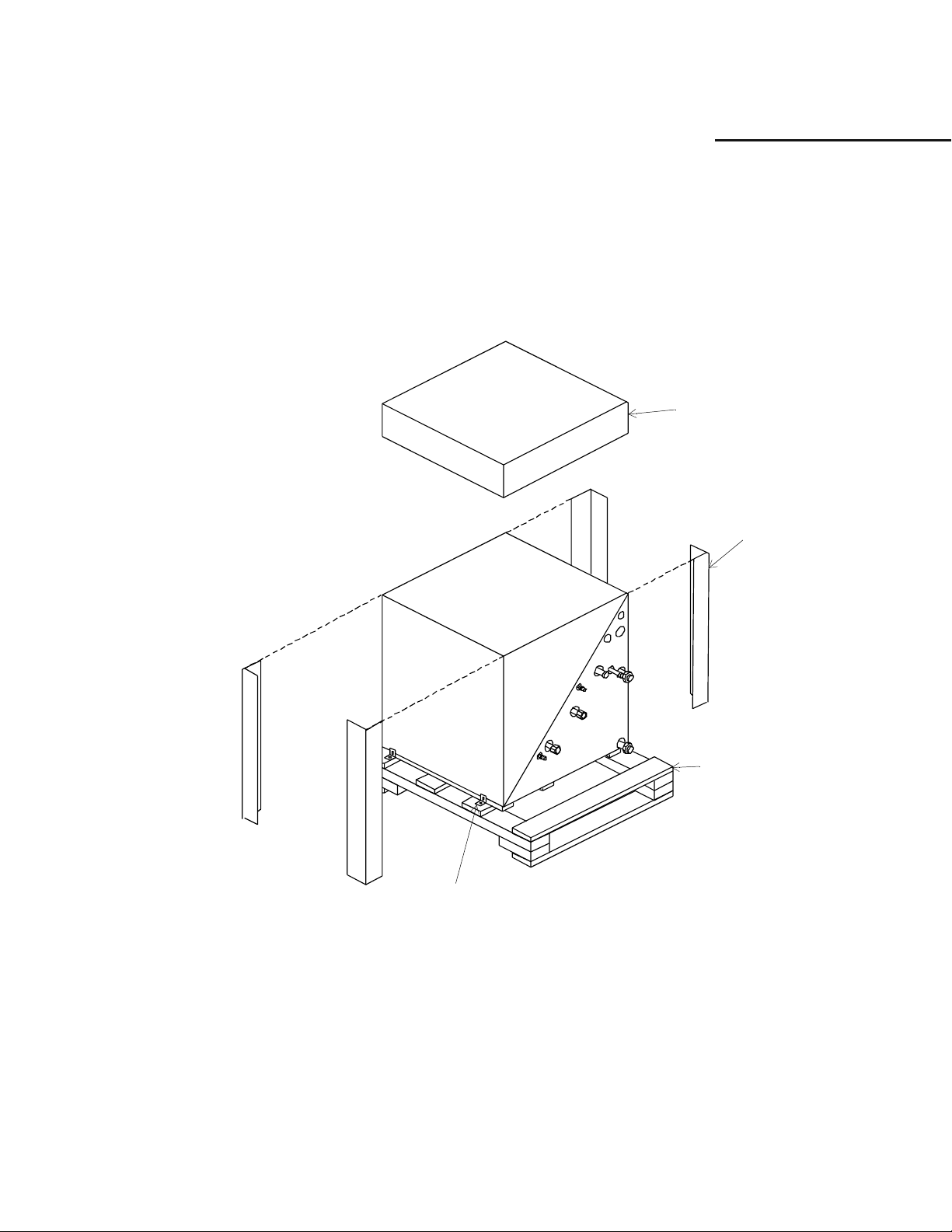
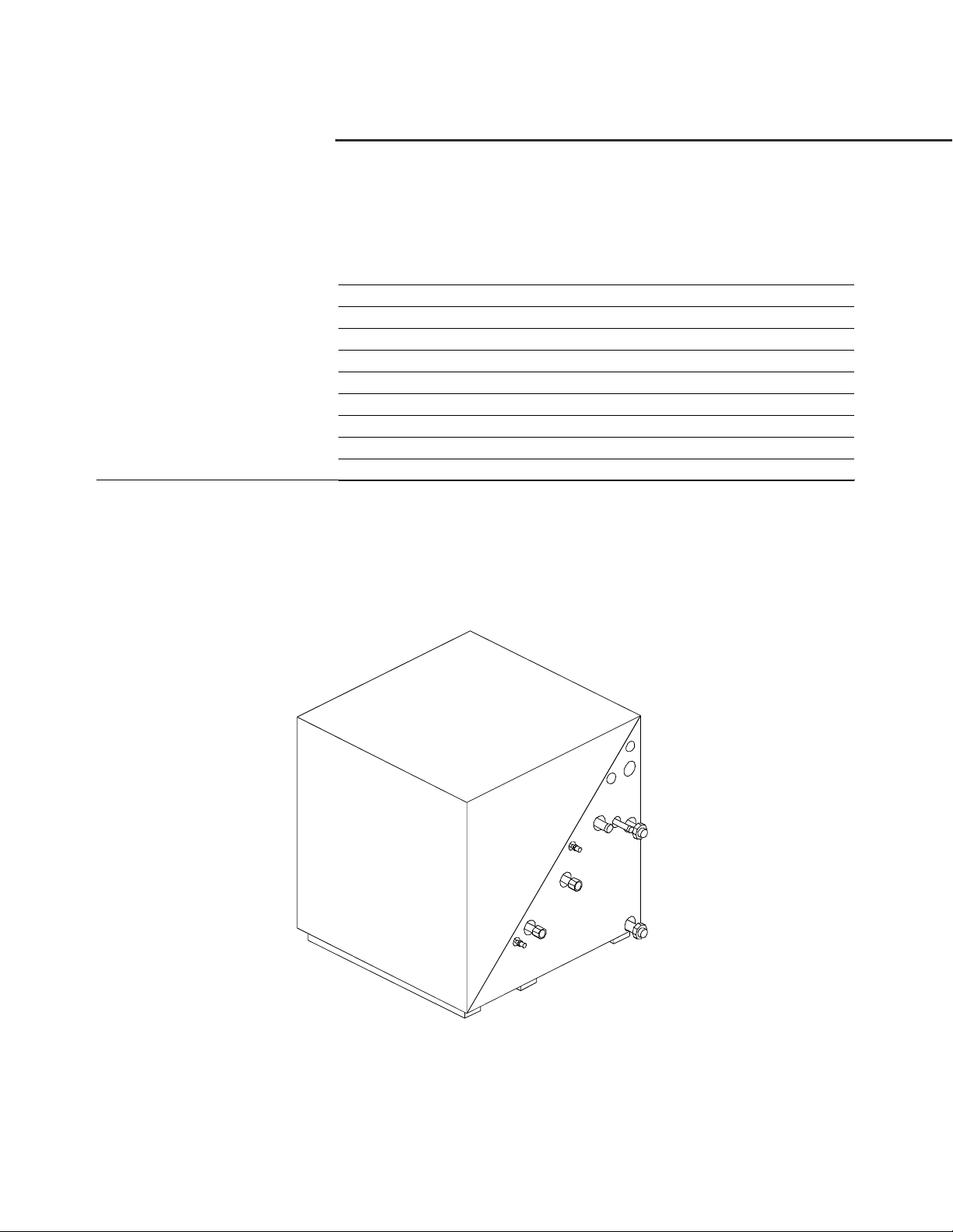
Receiving and Handling
The GSSD is packaged in clear stretch
wrap to allow immediate visual inspection. A careful inspection should
be made for shipping damage. All or-
ders are free on board (FOB) factory, therefore claims must be made
with the delivering carrier.
Carefully remove the stretch wrap and
the top cardboard corner pieces. Also
remove the (4) four shipping brackets
from the lower corners of the unit
along with the shipping skid.
Note:
Before installing the unit:
! Verify nameplate and model
number are correct.
! Inspect the overall quality and
appearance of the unit
.
Top Cover
Corners
Figure 1: Shipment Packaging
Wooden Skid
Shipping Brackets
6
Page 7

Installation-Location Considerations
Unit Size 024
Unit Size
024 163
23-5/16”
23”
LOW VOLTAGE
TOP VIEW
WATER REG
(SCHRADER PORT)
24-5/16”
LOW PSI SCHRADER
DESUPER OUT
1/2” NPT
DESUPER IN
1/2” NPT
1-1/8” DIA.
PUMP CONTROL
1-1/8” DIA.
SUCTION/DISCH
3/4” O.D.
10-7/16”
7-3/16”
Unit Weight
(lbs.)
6-7/16”
5-1/2”
HI PSI
SCHRADER
3-15/16”
1-7/16”
HI VOLTAGE
1-1/8” DIA.
LIQUID LINE
1/2” O.D.
WATER OUT
1” NPTI
13”
14-3/4”
13-15/16”
24-13/16”
8-7/16”
13-1/4”
WATER IN-1” NPTI
FRONT VIEW SIDE VIEW
7
2-1/16”
Page 8

Installation-Location Considerations
Unit Size 030-042
23”
TOP VIEW
23-5/16”
WATER REG
(SCHRADER PORT)
24-5/16”
LO PSI SCHRADER
Unit Size
DESUPER OUT
1/2” NPT
DESUPER IN
1/2” NPT
10-7/16”
Unit Weight
030 169
036 183
042 203
LOW VOLTAGE
1-1/8” DIA.
PUMP CONTROL
1-1/8” DIA.
SUCTION/DISCH
3/4” O.D.
7-3/16”
(lbs.)
6-7/16”
5-1/2”
HI PSI
SCHRADER
3-15/16”
1-7/16”
HI VOLTAGE
1-1/8” DIA.
LIQUID LINE
1/2” O.D.
WATER OUT
1” NPTI
13”
14-3/4”
13-15/16”
24-13/16”
8-7/16”
11-1/2”
WATER IN-1” NPTI
FRONT VIEW SIDE VIEW
8
2-1/16”
Page 9

Installation-Location Considerations
Unit Size 048-072
23”
TOP VIEW
23-5/16”
WATER REG
(SCHRADER PORT)
Unit Size
DESUPER OUT
1/2” NPT
Unit Weight
(lbs.)
048 214
060 244
072 277
LOW VOLTAGE
1-1/8” DIA.
PUMP CONTROL
1-1/8” DIA.
SUCTION/DISCH
3/4” O.D.
6-7/16”
5-1/2”
3-15/16”
1-7/16”
HI VOLTAGE
1-1/8” DIA.
LIQUID LINE
1/2” O.D.
WATER OUT
1” NPTI
24-13/16”
FRONT VIEW
24-5/16”
DESUPER IN
1/2” NPT
LO PSI SCHRADER
10-7/16”
9
7-3/16”
8-7/16”
11-1/2”
WATER IN-1” NPTI
SIDE VIEW
HI PSI
SCHRADER
19-1/16”
14-3/4”
13-15/16”
2-1/16”
Page 10

Location Consideration
! Unit should be placed on a level
surface in a indoor protected area.
Units should not be installed or
stored in an exterior environment.
Installation-Water Connections
! There should be approximately 2
to 3 feet of clearance available for
accessing the unit for service.
Accessiblity into unit is made by removing (2) two screws at the base of
the system. (See Figure 2).
The top half of the cube then lifts off.
Water Connections
The loop water connections brought to
the unit should be 1-inch male national
pipe threads.
The desuperheater (optional) connections should be 1/2-inch male national
pipe threads.
(See Figure 3 for water hook-up locations).
Remove these two
screws for internal unit
maintenance.
Desuperheater
Water-in
1/2” Female NPT
Desuperheater
Wat er -o ut
1/2” Female NPT
Figure 2: Unit access.
Wate r- ou t
1” Female NPT
Water-in
1” Female NPT
Refrigeration Connections
The refrigeration piping connections
are copper stub-outs. All refrigeration
connections are to be soldered into the
unit. It may be necessary to provide an
adapter to connect to the chosen air
handler.
sizes).
Note:
All refrigeration piping between the air
handler and the heat pump should be adequately insulated. Water piping should also
be insulated to reduce heat transfer and the
forming of condensation.
(See Figure 4 for location and
Unit Size
024
030-072
10
Suction
Line (O.D.)
3/4”
7/8”
Figure 3: Water hook-up locations.
Liquid Line
1/2” O.D.
Figure 4: Liquid and suction lines.
Page 11

Installation- Electrical
Field Wiring Connections
Power wiring to the unit should be installed per local electric codes by a
professional electrician.
The wires can be run to the unit
through the available knockouts
and to the control box in the top half of
the unit.
Control wiring to the unit is 24 volt.
The termination point identifications
for the terminal strip is identified per
Figure 5.
5
Compressor
Reversing valve (energized
6
in cooling)
1
Common
T-Stat
(X13510588020)
Manual changeover:
-two-stage heat
-one-stage cool
TWE
(Sizes 031-065)
GSSD
(Sizes 024-072)
GSSD 24V Field Wiring
RF
RG YO B
34561
Figure 5: Field wire connections.
Y
OC
2
1K1 to
Water Pump
and L1 / L2
W
W
W
1
1
2
W
2
Low Voltage
Pump Control
Hi Voltage
Terminal Strip
for Low Voltage
to TWE
Ground
11
Page 12

Installation- Electrical
Electrical System
The factory tested and installed control
box contains all of the necessary devices to control unit operation in both
the heating and cooling mode. A remote wall thermostat is necessary for
the control of the unit operation. See
General Information for thermostat information.
The nameplate provides information
for the application of either time delay
fuses or HACR circuit breakers for
branch circuit protection from the primary source of power. See Figure 6 for
component specifications.
.
Table 1: Electrical Data
Unit Model: GSSD 024 030 036 042 048 060 072
Volts-60HZ/1Phase 208-230 208-230 208-230 208-230 208-230 208-230 208-230
Compressor RLA 11.4 13.6 15 18.4 20.4 28 32.1
Compressor LRA 56 67 73 95 109 169 169
Electrical
Blower Motor RLA 3 5 5.6 5.6 5.6 7.4 7.4
Min. Circuit Amp. 14.7 17.4 19.2 23.4 25.9 35.4 40.5
Max Fuse Size 25 30 30 40 45 60 70
Desuperhtr Pump RLA 0.40 0.40 0.40 0.40 0.40 0.40 0.40
LOCKOUT
RELAY; 24VAC
FUSE; 2 AMP
480V
IF DESUPERHEATER
IS USED, THE FUSE
IS SHIPPED IN A CLOTH
BAG
10 POLE TERMINAL
STRIP; 20A-250V
Figure 6: Electric component location.
24VAC ENERGY LIMITING CLASS II
75VA BREAKER TYPE TRANSFORMER
COMPRESSOR RUN CAPACITOR
370V
COMPRESSOR CONTACTOR
3 POLE-24VAC
ALUMINUM
GROUND TERMINAL
Note: 208/230 volt equipment is designed to operate between 197 and 253 volts. Operation outside of these
ranges is likely to adversely affect the service life of the equipment.
12
Page 13

Pressure Switch
E
A high pressure switch is provided to
protect the compressor against excessive refrigeration pressure. The low
pressure switch should be wired in accordance with the type of freezestat
that is used. Trane factory supplies
two low pressure switches in the refrigerant circuit. The electrical connection is dependant upon which
freezestat (35 or 20 degree) is selected
The pressure switch is used to protect
the compressor against operation un-
HEAT EXCHANGER
7 PSIG LOW PRESSURE
SWITCH USED FOR 20
DEGREE FREEZESTAT
DESUPERHEATER
COMPRESSOR
Installation- Electrical
der low charge or catastrophic loss of
charge situations.
The low water temperature switch is
provided to protect the water-to-refrigerant heat exchanger from freezing. This device triggers the lock out
relay when leaving water temperatures
fall below the preset freezestat setting.
This device may be reset by cycling
power, but the system should be reviewed for operational error.
Important Notice
The low pressure switch should be
wired to activate at refrigerant
pressures of 35 psig when a 35
degree F freezestat is used; 7 psig
when a 20 degree F freezestat is
used. The installer should verify
that the correct freezestat and low
pressure switch are used in your
application. Misapplication can
produce a failure to the unit and
cause the warranty to be voided.
35-DEGREE F
OR
20-DEGREE F
FREEZESTAT
FILTER DRIER
EXPANSION VALVE
DESUPERHEATER PUMP
LIQUID LINE
WATER-OUT
SUCTION-DISCH
LINE
35 PSIG LOW PRESSUR
SWITCH USED FOR 35
DEGREE FREEZESTAT
WATER-IN
DESUPERHEATER-OUT
DESUPERHEATER-IN
REVERSING VALVE
13
Page 14

Typical Wiring Diagram
L2
L1
230V 6A MAX
TO WATERSOURCE PUMP
1TB3-1
16
1TB3-5
18
1TB3-6
25
5F3
1K1
L3
T3
1K1
L1
T1
6A,C,D,E
A,C
5F2
5F1
4
2A
6E
7C
C
1C1
7A
4S5
6F
A
A
5C
4S6
2B1
6H
6B1
5C
DESUPERHEATER
PUMP
6G
R
S
C
G
F,G
1K3
C2
C1
A
1K3
19A
4S3
20A
4S4
21A
5
4S1
C
A
1TB3-7
23
1TB3-8
1TB3-2
23
A
D,F
16
1K1
1K3-24
D
1K1-12,14
A
4S4
F
DEVICE
1K1
1K3
1TB3
1C1
2B1
4L1
4S1
4S3
4S4
4S5
4S6
5F1,2,3
6B1
LEGEND
DESCRIPTION
COMPRESSOR CONTACTOR
LOCKOUT RELAY
TERMINAL STRIP
COMPRESSOR RUN CAPACITOR
COMPRESSOR
REVERSING VALVE
FREEZE PROTECTION SW 1
HIGH PRESSURE SW
LOW PRESSURE SW
DISCHARGE LINE T’STAT
ENTERING WATER T’STAT
FUSE
DESUPERHEATER PUMP
NOTES:
1.
2.
4
14
UNLESS OTHERWISE NOTED. ALL SWITCHES ARE
SHOWN AT 77 DEGREES F AT ATMOSPHERIC
PRESSURE. AT 50% RELATIVE HUMIDITY, WITH
ALL UTILITIES TURNED OFF, AND AFTER A
NORMAL SHUTDOWN HAS OCCURRED.
DASHED LINES INDICATE RECOMMENDED FIELD
WIRING BY OTHERS. DASHED LINE ENCLOSURES
AND/OR DASHED DEVICE OUTLINES INDICATE
COMPONENTS PROVIDED BY THE FIELD. DOT
LINE ENCLOSURES INDICATE ALTERNATE
CIRCUITRY OR AVAILABLE SALES OPTIONS.
SOLID LINES INDICATE FACTORY WIRING.
BEFORE INSTALLING FUSE IN DESUPERHEATER CIRCUIT, BE
CERTAIN PUMP PIPING IS CONNECTED AND FILLED WITH
WATER
Page 15

Loop Water Applications
It should be noted that there is no mechanical difference between geothermal (closed loop) and ground water
(open loop) GSSD units. Generally in
a closed loop application, there is a
percentage of antifreeze in the water.
In these applications, the 20 degree F
freezestat, along with the 7 psig safety
pressure switch may be used. All other
applications require the 35 degree F
freezestat, along with the 35 psig safety pressure switch.
Ground Water Applications
(Open Loop)
Where an existing or proposed well
can provide an ample supply of suitable quality water, open ground water
systems may be very efficient. However, there are several potential considerations that should be addressed
prior to installation of an open loop
system:
! A 60 mesh straining device must
be placed in the incoming water
line. The sand filter/separator
helps ensure clean water by
removing any particles in the
water. Note: A filter/separator
should be available from your
local dealer.
! Even if plenty of water is
available, there needs to be an
acceptable way to discharge it
after it has passed through the heat
pump. A three-ton heat pump is
Installation - Water Loop
apt to use one million gallons of
water per year. It may be
necessary to install a recharge well
to return the water to the aquifer.
In some soils, this may be difficult
to do.
! Water quality must also be
acceptable to maintain the
integrity and life of the unit. The
loop fluid must have minimal
suspended solids, and must be
non-corrosive to copper or brass.
See Table 2 for specifications.
Table 2: Water Supply Requirements
Scaling
Calcium and
magnesium salts
(total hardness)
Corrosion
pH 7.5-9.5
Hydrogen Sulfide Less than 1 ppm
Sulfates Less than 25 ppm
Carbon dioxide Less than 75 ppm
Chloride Less than 125 ppm
Total dissolved solids
(TDS)
Biological Growth
Iron bacteria Low
Erosion
Suspended Solids Low
Less than 350 ppm
Less than 1000 ppm
Ground Water Applications
(Closed Loop)
Loop sizing should be done by a qualified installer to insure maximized unit
performance.
In areas where the ground water temperature is 66 degrees F or less, the
earth coupling fluid requires at least a
15 percent by volume antifreeze solution. Using Table 3, calculate the approximate water volume of the
system. Add one gallon to your total as
an allowance for water in each heat
pump and connection hoses. Check
the earth coupling design for the antifreeze percentage required. MORE IS
NOT BETTER-Do no exceed the
amount indicated in the design specifications.
Table 3: Water Volume
Volume in Gallons/100 Ft.
Pipe Size 3/4” 1”
Vo l um e
SDR-11
Vo l um e
SCH 40
3.02 4.73 7.52 9.85 15.4
2.77 4.49 7.77 10.6 17.4
Use only FULL STRENGTH INHIBITED PROPYLENE GLYCOL OR
METHANOL, not solutions which
have already been diluted.
Note:
The water quality of the fluid loop
should meet the same specifications
as in Table 2.
1 1/4” 1 1/2”
2”
15
Page 16

Refrigerant Charge
GSSD Units Coupled with
TWE Air Handlers
The GSSD IS coupled with the TWEE series. Table 4 may be used to determine the amount of charge necessary
for the split unit system without any
refrigerant line connecting the two.
Table 5 can be used to determine the
amount of refrigerant needed for lines.
By adding the two weights together,
the approximate total system charge
can be obtained. For fine tuning the
charge, see Units Coupled with Non-
TWE Air Handlers and Fine Tuning
in next section.
Table 4: R22 Requirements
GSSD
Model
Number
GSSD024 TWE031E 5.0
GSSD030 TWE031E 5.0
GSSD036 TWE040E 8.25
GSSD042 TWE040E 9.25
GSSD048 TWE065E 9.25
GSSD060 TWE065E 10.125
GSSD072 TWE065E 10.75‘
TWE
Model
Number
Lbs of R22
for both
GSSD & TWE
Table 5: R22 requirement per foot of line
O.D. Tube
Size
1/4-inch 0.352 N/A
3/8-inch 0.928 N/A
1/2-inch 1.152 0.032
5/8-inch 1.840 0.048
3/4-inch 4.272 0.064
7/8-inch N/A 0.080
1 1/8-inch N/A 0.144
Liquid Line
(oz.)
Suction
Line (oz.)
Note:
If piping runs exceed 50 feet, the next
highest pipe size should be used.
GSSD Units Coupled with
Non-TWE Air Handlers and
Fine Tuning
1. Place the GSSD system in the
cooling mode.
2. Throttle down the water flow
with a ball valve until the leaving
fluid temperature is 95 degrees F.
3. Charge the system unit until a
level of 10 degrees superheat is
achieved. To determine superheat, an accurate suction line
temperature needs to be taken
along with the suction pressure.
4. The sub-cooling will be approximately 8 degrees to 5 degrees F.
5. Allow system to run 20 minutes
for conditions to stabilize
before measuring the superheat.
6. Return water flow to 3 gpm per
nominal ton of capacity.
16
Page 17

Refrigeration System
! Compressor: The unit includes a
high efficiency scroll compressor
with and internal vibration isolator
that absorbs starting and stopping
energy. It also contains an internal
overload protection. External
vibration isolation is provided by
rubber mounting devices located
underneath the mounting base of
the compressor.
! Water-to-Refrigerant Heat
Exchanger: The water-torefrigerant heat exchanger is a
high quality stainless steel braze
plate heat exchanger. This
stainless material offers
exceptional corrosion resistance.
The heat exchanger has a working
pressure rating of 450 psig on both
the refrigerant and water sides. To
help ensure clean water for the
water-to-refrigerant heat
exchanger, Trane recommends a
sand filter/separator for open loop
systems.
! Freezestat and Lock-out Relay: A
freezestat is included to protect the
unit from unusually cold loop fluid
temperatures or no fluid flow
conditions. A 35 degree F
freezestat is necessary in open
Refrigeration System
loop applications and closed loop
applications without adequate
antifreeze. A 20 degree F
freezestat may be used with closed
loop applications with antifreeze
solution only. A lockout relay
circuit consisting of three safety
devices (low pressure, high
pressure, and Freezestat) will
trigger the lockout relay to shut off
the compressor, the loop pumps
and the desuperheater pump
(optional) when a safety is tripped.
A triggered lock-out relay is a key
indication that there is a problem
in the system and service may be
necessary. The safety that caused
the lockout relay to energize will
reset itself after approximately
five minutes. If the lockout relay is
manually reset by power
interruption prior to this five
minute period, the unit will be
unable to run. To manually reset
the lockout relay, the disconnect or
system switch at the thermostat
must be toggled.
! Reversing Valve: The reversing
valve is a pilot operated sliding
piston type with replaceable
encapsulated magnetic coil. The
reversing valve is energized when
the unit is in the cooling mode and
de-energizes in the heating mode.
! Refrigerant Tubing: All refrigerant
tubing is constructed of copper.
The low temperature refrigerant
lines are factory insulated with a 3/
8-inch thick elastomeric insulation
(UL 94V-5 rated), with a flame
spread rating of less than 25 and
smoke density rating of less than
50. It has been tested in
accordance with ASTM-85.
! Refrigerant Metering: The
refrigeration circuit is provided
with a bi-directional thermal
expansion valve to allow operation
with entering water temperatures
from 25 degrees F to 120 degrees
F.
! Liquid Line Filter: The unit
contains a bi-directional liquid line
filter drier to remove any
contaminants within the
refrigeration circuit.
! Servicing Pressure Ports: The
equipment is provided with both
high and low pressure schraeder
ports. The ports are located
outside the unit case for
convenient access.
17
Page 18

Miscellaneous Equipment
Accessory Items
Note:
The following equipment may be purchased through the nearest Trane distributor.
! Water Regulating Valve Assembly:
The water regulating valve
assembly consists of a direct
acting valve and a reverse acting
valve. The direct acting valve
opens in response to an increase in
discharge pressure during the
cooling cycle. The reverse acting
valve opens in response to a
decrease in suction pressure
during the heating cycle. Water
regulating valves should be used
where low flow, and low or high
fluid temperature conditions could
occur.This option is beneficial
with open loop systems, but not
necessary.
! Motorized Water Valve for open
loop systems: The motorized water
valve is installed on the return line
of the system between the loop
and the loop pump module. This
isolation device is a much less
expensive and very effective
alternative. When the compressor
begins running, the valve will
open, allowing water to flow
through the unit. As the
compressor shuts down, the valve
slowly closes off. The main
purpose of the automatic device is
to prevent water hammer, by
keeping the pressure raised in the
loop system during off cycles.
! Electric Strip Heaters: If the ETL
listed strip heaters are used, they
can be installed directly inside the
TWE air handler. These heaters
are rated at 230 volts and provide
electric heat for both supplemental
and emergency heat requirements.
There are a number of heater
capacities available.
! Pump Module: The pump module
and the hose kit make a complete
self-contained pumping package
for the earth-coupled heat pump
system. These kits contain all the
necessary components for the
installation, operation and
maintenance of the water circuit of
a closed loop geothermal
application. Standard pump
module features include insulated
Grundfos pumps, insulated
cabinet, optional cast iron or
bronze pumps, 3-way brass valves
and the choice of a one or two
pump module.
! Hose Kits: The hose kits include
two brass, 1-inch male pipe thread
(MPT) by barb-fittings, two brass
90 degree 1-inch, MPT by barbelbows with pressure/temperature
ports and 10 feet of rubber hose
with 4 hose clamps.
! Sand Filter/Separator: A sand
filter/separator helps ensure clean
water for the water-to-refrigerant
heat exchanger. The recommended
strainer is 60 mesh or greater. The
strainer keeps particles and debris
from entering the system.
18
 Loading...