

Page 1
Discharge Air
Nozzle Kits
Installation GPND-IN-1
Library Service Literature
Product Section Air Terminal Devices & Heat Products
Product Gas Unit Heaters
Model GPND/GPPD
Literature Type Installation
Sequence 1
Date August 1997
File No. SV-TD-UH-GPND-IN-1-897
Supersedes New
Models
GAND
GAPD
GBND
GBPD
GCND
GCPD
GEND
GEPD
GHND
GHPD
GKND
GKPD
GPND
GPPD
Sizes 100 through 400
Since the Companyhas a policy ofcontinuous productimprovement, it reserves the right to changespecifications and
design without notice.
© American Standard Inc. 1997
Page 2
General Information
Table of Contents
General Information ................... 2
Literature Change History ................ 2
Warnings and Cautions ................. 2
Description ........................ 2
Installation ........................ 3
30° Nozzle Kit ...................... 3
45° Nozzle Kit ...................... 4
60° Nozzle Kit ...................... 5
90° Nozzle Kit ...................... 6
5-Way Blow Down Nozzle Kit .............. 7
Y-Splitter Nozzle Kit ................... 7
Literature Change History
GPND-IN-1 (August 1997)
Original issue of the manual.
Warnings and Cautions
Warnings and Cautions appear at
appropriate sections throughout
this manual.
WARNINGS!
alert the installer, owner,
operator or service personnel
to potential hazards which if
not avoided could result in
death or serious personal injury.
Cautions:
alert personnel to conditions
which if not avoided may result
in minor or moderate injury.
Also alerts against unsafe practices causing equipment
damage.
Shipping Instructions
Before installing the nozzle kit, be
sure to confirm that the proper kit
has been sipped.
If a thorough inspection of the kit
reveals damage or material
shortages, file a claim with the
carrier immediately. Specify the
extent and type of damage found,
and notify the appropriate Trane
sales office. Do not install a
damaged nozzle kit without the
Trane sales representative’s
approval!
Description
The nozzle kits are used to direct
discharge air on unit heaters with
a variety of angles available.
2 GPND-IN-1
Page 3
WARNING!
Disconnect the power source
before installing this kit to
prevent death or serious
personal injury due to
electrical shock.
For Use On Propeller and
Blower Unit Heaters
Natural or Power Vent
Kit Contents (Unassembled)
(2) Side Panels—L.H. & R.H.
(1) Top Panel
(1) Bottom Cross Brace
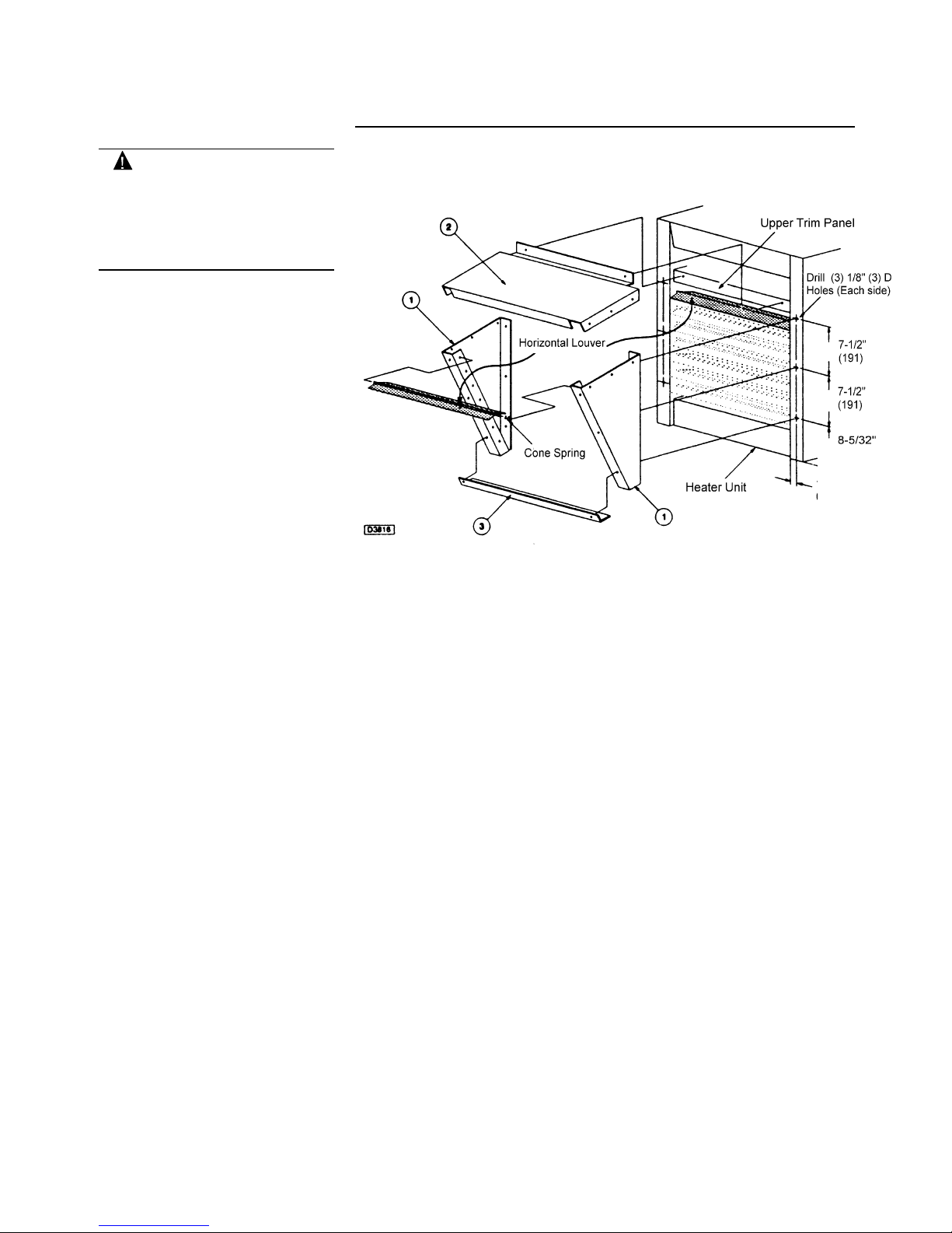
Installation—30° Nozzle Kit
(1) Bag of #8 Drill Screws
The following steps for
assembling are recommended in
sequence:
1. Remove seven (7) horizontal
louvers and louver cone
springs from unit heater and
set aside. (Note louver and
spring positions).
2. Drill three (3) 1/8" diameter
holes in each unit heater “side
panel” to dimensions shown,
(see drawing).
3. Fasten L.H. (Item 1) and R.H.
(Item 2) side panels to unit
heater “side panels” with three
(3) drill screws each using
holes drilled in Step 2 above.
4. Attach “top panel” (Item 3) to
nozzle side panels (Items 1 &
2) with six (6) drill screws.
5. Fasten “top panel” (Item 3) to
heater’s “upper trim panel”
utilizing existing screws at
each end. Then, using
remaining holes as template,
drill through with 1/8" diameter
drill and fasten with drill
screws.
6. Attach and fasten “bottom
cross brace” (Item 4) with two
(2) drill screws.
7. Install six (6) of the seven (7)
louvers and louver cone
springs removed from the unit
heater in Step 1.
GPND-IN-1 3
Page 4

WARNING!
Disconnect the power source
before installing this kit to
prevent death or serious
personal injury due to
electrical shock.
For Use On Propeller and
Blower Unit Heaters
Natural or Power Vent
Installation—45° Nozzle Kit
Recommended procedure for the
nozzle installation to the unit
heater:
1. Standard (Natural Vent)
Units
1. Remove the louvers and cone
springs from the discharge
end of the unit heater.
2. Remove the upper front trim
panel (located directly above
the heat exchanger opening).
3. Install the nozzle by simply
hooking the top panel flange
of the nozzle over the top
flange of the heat exchanger.
The nozzle side panels should
slide inside the heat
exchanger opening.
4. Secure the bottom of the
nozzle to the lower front trim
panel of the unit heater, by
drilling through and using the
screws provided.
2. High Efficiency (Power Vent)
Units
1. Remove the louvers and cone
springs from the discharge
end of the unit heater
2. Remove the screws from the
upper front trim panel of the
unit heater.
3. Install the nozzle by securing
the top panel of the nozzle to
the face of the upper front trim
panel, using the screws that
were just removed from each
end. The sides of the nozzle
should slide into the heat
exchanger opening.
4. Add the remaining screws in
the locations provided in the
nozzle top panel; drill through
into the unit heater trim panel.
5. Secure the bottom of the
nozzle to the lower front trim
panel of the unit heater, by
drilling through and using the
screws provided.
4 GPND-IN-1
Page 5

WARNING!
Disconnect the power source
before installing this kit to
prevent death or serious
personal injury due to
electrical shock.
For Use On Propeller and
Blower Unit Heaters
Natural or Power Vent
Kit Contents (Unassembled)
(2) L.H. Side Panels
Installation—60° Nozzle Kit
(2) R.H. Side Panels
(1) 30° Top Panel
(1) 60° Top Panel
(1) Bottom Cross Brace
(1) Bag of #8 Drill Screws
The following steps for
assembling are recommended in
sequence:
1. Remove seven (7) horizontal
louvers and louver cone
springs from unit heater and
set aside. (Note louver and
spring positions).
2. Drill three (3) 1/8" diameter
holes in each unit heater “side
panel” to dimensions shown,
(see drawing).
3. Fasten L.H. (Item 1) and R.H.
(Item 2) side panels to unit
heater “side panels” with three
(3) drill screws each using
holes drilled in Step 2 above.
4. Attach “top panel” (Item 3) to
nozzle side panels (Items 1 &
2) with six (6) drill screws.
5. Fasten “top panel” (Item 3) to
heater’s “upper trim panel”
utilizing existing screws at
each end. Then, using
remaining holes as template,
drill through with 1/8" diameter
drill and fasten with drill
screws.
6. Fasten second L.H. (Item 1)
and second R.H. (Item 2) side
panels to first side panels
(Items 1 and 2) with three (3)
drill screws each.
7. Attach 60° “top panel° (Item 4)
to second nozzle side panels
(Items 1 and 2) with six (6)
drill screws.
8. Fasten rear horizontal flange
of top panel (Item 4) to front
horizontal flange of top panel
(Item 3) with drill screws.
9. Attach and fasten “bottom
cross brace” (Item 4) with two
(2) drill screws.
10.Install six (6) of the seven (7)
louvers and louver cone
springs removed from the unit
heater in Step 1.
GPND-IN-1 5
Page 6

WARNING!
Disconnect the power source
before installing this kit to
prevent death or serious
personal injury due to
electrical shock.
For Use On Propeller and
Blower Unit Heaters
Natural or Power Vent
Installation—90° Nozzle Kit
Recommended procedure for the
nozzle installation to the unit
heater:
1. Standard (Natural Vent)
Units
1. Remove the louvers and cone
springs from the discharge
end of the unit heater.
2. Remove the upper front trim
panel (located directly above
the heat exchanger opening).
3. Install the nozzle by simply
hooking the top panel flange
of the nozzle over the top
flange of the heat exchanger.
The nozzle side panels should
slide inside the heat
exchanger opening.
4. Secure the bottom of the
nozzle to the lower front trim
panel of the unit heater, by
drilling through and using the
screws provided.
2. High Efficiency (Power Vent)
Units
1. Remove the louvers and cone
springs from the discharge
end of the unit heater
2. Remove the screws from the
upper front trim panel of the
unit heater.
3. Install the nozzle by securing
the top panel of the nozzle to
the face of the upper front trim
panel, using the screws that
were just removed from each
end. The sides of the nozzle
should slide into the heat
exchanger opening.
4. Add the remaining screws in
the locations provided in the
nozzle top panel; drill through
into the unit heater trim panel.
5. Secure the bottom of the
nozzle to the lower front trim
panel of the unit heater, by
drilling through and using the
screws provided.
6 GPND-IN-1
Page 7

5-Way Blow Down Nozzle Kit
WARNING!
Disconnect the power source
before installing this kit to
prevent death or serious
personal injury due to
electrical shock.
For Use On Blower Unit
Heaters
Natural or Power Vent
Installation
Y-Splitter Nozzle Kit
WARNING!
Disconnect the power source
before installing this kit to
prevent death or serious
personal injury due to
electrical shock.
For Use On Propeller and
Blower Unit Heaters
Natural or Power Vent
Use directions for 90° nozzle kit
assembly and installation.
GPND-IN-1 7
Use directions for 90° nozzle kit
assembly and installation.
 Loading...