

Trane Force-Flo Cabinet Heater Air Terminal Devices Catalogue
Product Catalog
Force-Flo™ Cabinet Heater
Air Terminal Devices
Horizontal and Vertical
Sizes 02–12
May 2012 CAB-PRC001-EN
Introduction
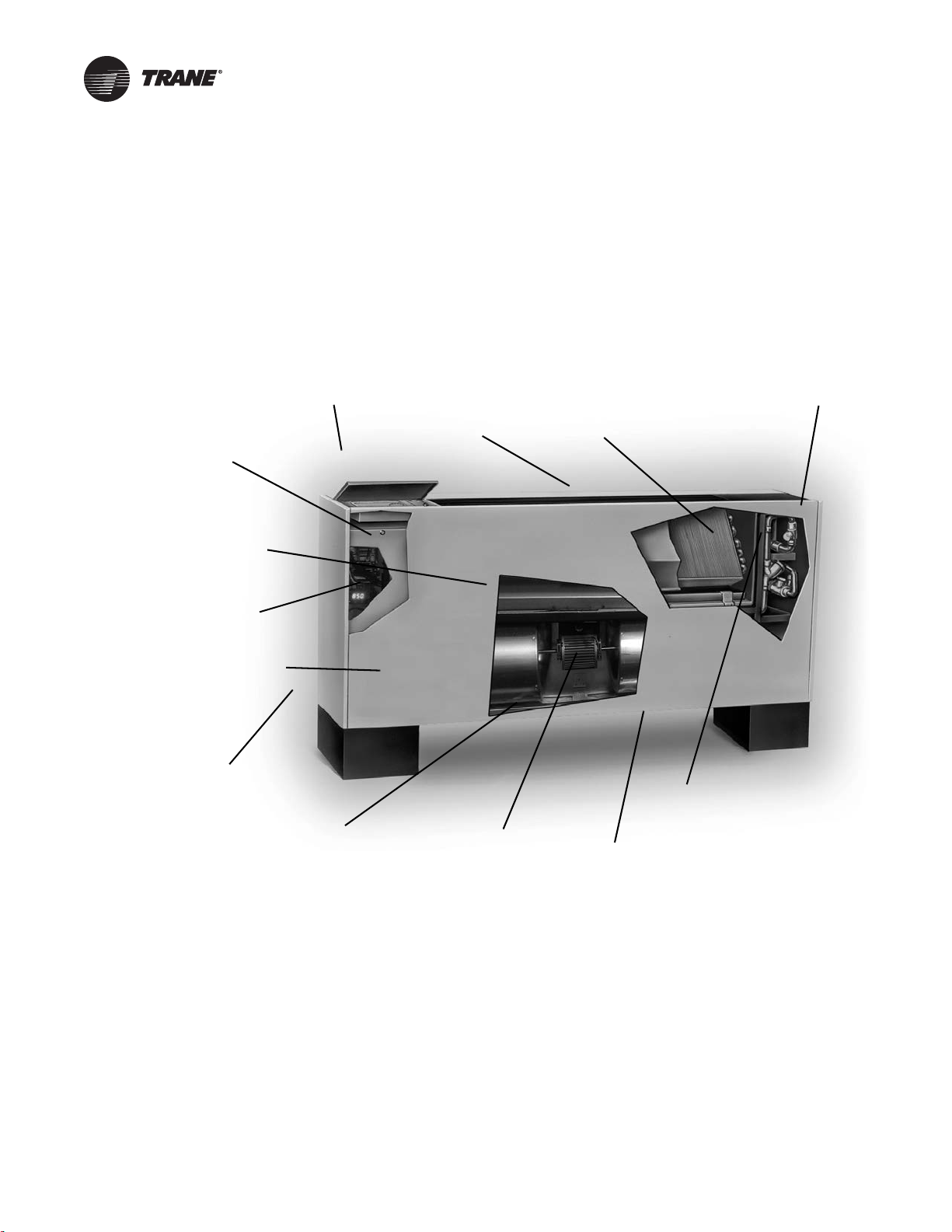
Factory-assembled, -installed,
and -tested piping package
with IAQ drain pan to collect
condensate.Two-, three-, or
four-row coils.
Quiet operation.
Smaller unit footprint.
Factory-installed and
-tested controls.
Removable, noncorrosive,
positively-sloped drain pan
that’s easy to clean.
Easy-to-remove fan assembly.
16-gage steel construction.
Cleanable closed-cell
insulator (non-fiberglass).
Easy filter access
without front panel
removal.
Damper allows up
to 100% fresh air.
Build in field service tool
with real language LED
Energy efficient
electronically
commutated motor
(ECM)
Trane has redesigned the traditional cabinet heater to lead the industry in:
• indoor air quality (IAQ) features
• easy installation and maintenance
• high quality and durability
• advanced controls
© 2012 Trane All rights reserved CAB-PRC001-EN
Revision History
The revision of this literature dated 08 May 2012 includes information for Tracer™ UC400 controls,
coil performance updates, and revised performance table formats per new AHRI listing
requirements.
Trademarks
Force-Flo, Integrated Comfort, Rover, TOPSS, Tracer, Tracer Summit, Trane, and the Trane logo are
trademarks of Trane in the United States and other countries. All trademarks referenced in this
document are the trademarks of their respective owners.

Table of Contents
Introduction . . . . . . . . . . . . . . . . . . . . . . . . . . . . . . . . . . . . . . . . . . . . . . . . . . . . . . . . . . . . 2
Features and Benefits . . . . . . . . . . . . . . . . . . . . . . . . . . . . . . . . . . . . . . . . . . . . . . . . . . . 5
Model Number Descriptions . . . . . . . . . . . . . . . . . . . . . . . . . . . . . . . . . . . . . . . . . . . . . 7
General Data . . . . . . . . . . . . . . . . . . . . . . . . . . . . . . . . . . . . . . . . . . . . . . . . . . . . . . . . . . . 9
Performance Data . . . . . . . . . . . . . . . . . . . . . . . . . . . . . . . . . . . . . . . . . . . . . . . . . . . . . 22
Model A, Vertical Concealed . . . . . . . . . . . . . . . . . . . . . . . . . . . . . . . . . . . . 9
Model B, Vertical Cabinet . . . . . . . . . . . . . . . . . . . . . . . . . . . . . . . . . . . . . . . 9
Model C, Horizontal Concealed . . . . . . . . . . . . . . . . . . . . . . . . . . . . . . . . . 10
Model D, Horizontal Cabinet . . . . . . . . . . . . . . . . . . . . . . . . . . . . . . . . . . . . 11
Model E, Horizontal Recessed . . . . . . . . . . . . . . . . . . . . . . . . . . . . . . . . . . 12
Model F, Vertical Wall Hung Cabinet . . . . . . . . . . . . . . . . . . . . . . . . . . . . . 12
Model H, Vertical Recessed . . . . . . . . . . . . . . . . . . . . . . . . . . . . . . . . . . . . 13
Model J, Vertical Cabinet Slope Top . . . . . . . . . . . . . . . . . . . . . . . . . . . . . 13
Model M, Inverted Vertical Concealed . . . . . . . . . . . . . . . . . . . . . . . . . . . . 14
Model N, Inverted Vertical Recessed . . . . . . . . . . . . . . . . . . . . . . . . . . . . . 14
Electric Heat . . . . . . . . . . . . . . . . . . . . . . . . . . . . . . . . . . . . . . . . . . . . . . . . . 16
Factory-Installed Piping Packages . . . . . . . . . . . . . . . . . . . . . . . . . . . . . . . 17
Horizontal Concealed, Horizontal Recessed, Vertical Recessed, Inverted
Vertical Recessed . . . . . . . . . . . . . . . . . . . . . . . . . . . . . . . . . . . . . . . . . . . . 23
Vertical Concealed . . . . . . . . . . . . . . . . . . . . . . . . . . . . . . . . . . . . . . . . . . . . 24
Horizontal Cabinet, Vertical Cabinet, Inverted Vertical Cabinet . . . . . . . 25
Vertical Slope Top Cabinet . . . . . . . . . . . . . . . . . . . . . . . . . . . . . . . . . . . . . 26
Horizontal Concealed, Horizontal Recessed, Vertical Recessed, Horizontal
Cabinet . . . . . . . . . . . . . . . . . . . . . . . . . . . . . . . . . . . . . . . . . . . . . . . . . . . . . 27
Vertical Concealed . . . . . . . . . . . . . . . . . . . . . . . . . . . . . . . . . . . . . . . . . . . . 28
Controls . . . . . . . . . . . . . . . . . . . . . . . . . . . . . . . . . . . . . . . . . . . . . . . . . . . . . . . . . . . . . . 29
ECM Engine Controller . . . . . . . . . . . . . . . . . . . . . . . . . . . . . . . . . . . . . . . . 29
Control Options . . . . . . . . . . . . . . . . . . . . . . . . . . . . . . . . . . . . . . . . . . . . . . 30
Manual Fan Mode Switch . . . . . . . . . . . . . . . . . . . . . . . . . . . . . . . . . . . . . . 30
Customer Supplied Terminal Interface (CSTI) . . . . . . . . . . . . . . . . . . . . . 31
Tracer Controls . . . . . . . . . . . . . . . . . . . . . . . . . . . . . . . . . . . . . . . . . . . . . . 32
Sequence of Operation . . . . . . . . . . . . . . . . . . . . . . . . . . . . . . . . . . . . . . . . 34
Zone Sensor Options . . . . . . . . . . . . . . . . . . . . . . . . . . . . . . . . . . . . . . . . . 37
Control Features . . . . . . . . . . . . . . . . . . . . . . . . . . . . . . . . . . . . . . . . . . . . . 38
Tracer ZN520 and UC400 Additional Features . . . . . . . . . . . . . . . . . . . . . 39
End Device Options . . . . . . . . . . . . . . . . . . . . . . . . . . . . . . . . . . . . . . . . . . . 39
Electrical Data . . . . . . . . . . . . . . . . . . . . . . . . . . . . . . . . . . . . . . . . . . . . . . . . . . . . . . . . . 41
Dimensions and Weights . . . . . . . . . . . . . . . . . . . . . . . . . . . . . . . . . . . . . . . . . . . . . . . 46
Vertical Concealed, Model A . . . . . . . . . . . . . . . . . . . . . . . . . . . . . . . . . . . 46
Vertical Cabinet, Model B . . . . . . . . . . . . . . . . . . . . . . . . . . . . . . . . . . . . . . 47
Horizontal Concealed, Model C . . . . . . . . . . . . . . . . . . . . . . . . . . . . . . . . . 48
Horizontal Cabinet, Model D . . . . . . . . . . . . . . . . . . . . . . . . . . . . . . . . . . . . 49
CAB-PRC001-EN 3

Horizontal Recessed, Model E . . . . . . . . . . . . . . . . . . . . . . . . . . . . . . . . . . 50
Vertical Wall Hung Cabinet, Model F . . . . . . . . . . . . . . . . . . . . . . . . . . . . . 51
Vertical Recessed, Model H . . . . . . . . . . . . . . . . . . . . . . . . . . . . . . . . . . . . 52
Vertical Slope Top, Model J . . . . . . . . . . . . . . . . . . . . . . . . . . . . . . . . . . . . 53
Inverted Vertical Cabinet, Model M . . . . . . . . . . . . . . . . . . . . . . . . . . . . . . 54
Inverted Vertical Recessed, Model N . . . . . . . . . . . . . . . . . . . . . . . . . . . . . 55
Coil Connections . . . . . . . . . . . . . . . . . . . . . . . . . . . . . . . . . . . . . . . . . . . . . 56
Fresh Air Opening Locations-Horizontal Units Models C, D, and E . . . . 57
Fresh Air Opening Locations-Vertical Units Models A, B, F, and J . . . . . 58
Wall Box . . . . . . . . . . . . . . . . . . . . . . . . . . . . . . . . . . . . . . . . . . . . . . . . . . . . 59
Projection Panel . . . . . . . . . . . . . . . . . . . . . . . . . . . . . . . . . . . . . . . . . . . . . . 60
Mechanical Specifications . . . . . . . . . . . . . . . . . . . . . . . . . . . . . . . . . . . . . . . . . . . . . . 61
Force-Flo Cabinet Heater Mechanical Specifications . . . . . . . . . . . . . . . . 61
Piping Components . . . . . . . . . . . . . . . . . . . . . . . . . . . . . . . . . . . . . . . . . . . 66
4 CAB-PRC001-EN

Features and Benefits
The Force-Flo cabinet heater meets the standards of today’s market, as well as the anticipated
needs of tomorrow’s market. The tradition that company founder Reuben Trane began in 1913
continues with the latest generation of cabinet heaters from Trane.
The Force-Flo cabinet heater is the leader in these key areas:
• Energy Efficiency
• Indoor Air Quality (IAQ)
• Controls
•Flexibility
•Quality
• Serviceability
Today’s HVAC market is concerned with issues suc
demand a change in HVAC products. In addition, renovation has overtaken new construction in the
cabinet heater market - demanding a design that caters to renovation issues. Trane is concerned
with these issues, too. That’s why we designed the Force-Flo cabinet heater as an integral part of
the company’s system solutions with standard IAQ-related features that comply with ASHRAE 62.
Energy Efficiency
Trane’s commitment to providing premium quality products has led to the exclusive use of
Electronically Commutated Motors (ECM) in all fan coil models. These brushless DC motors
incorporate the latest technology for optimized energy efficiency, acoustical abatement,
maintenance free and extended motor life. Each motor has a built-in microprocessor that allows
for programmability, soft ramp-up, better airflow control, and serial communication.
• Trane units equipped with ECMs are significantl
Split Capacitor (PSC) motor.
• Lower operating costs on average of 50 percent (versus a PSC motor).
• The Reduced FLA feature allows units to ship w
typical ECM unit.
h as indoor air quality (IAQ) and CFCs that
y more efficient than the standard Permanent
ith a nameplate FLA rating much lower than a
IAQ Design
• Closed-cell insulation is standard on all units to help prevent fiberglass in the airstream.
• Easy filter access encourages frequent changing.
• Force-Flo cabinet heaters have a blow-thru design.
Controls
• This is the industry’s first solution that is factory mounted, wired and programmed for infinite
modulation of fan speed based on space loads, using the UC400.
• Auto Fan Speed control with the Tracer ZN520 ramps the fan speed up and down to meet space
ads.
lo
• All controls are factory-mounted and tested to minimize field setup and improve reliability.
• Controls are wired with a 24 Vac transformer to keep only a single source power connection
requirement to the unit.
• All wall-mounted zone sensors require only low voltage control wir
unit control box. (No line voltage.)
• The random startup feature helps reduce electrical demand peaks by randomly staggering
ultiple units at startup.
m
• Occupied/unoccupied operation allows the controller to utilize unoccupied temperature
oints for energy savings.
setp
CAB-PRC001-EN 5
ing from the device to the

Features and Benefits
• Warm-up energy feature is standard with Trane controls.
• Continuous fan or fan cycling is avail
• Monitor unit operation using Tracer SC building management system with Tracer ZN510.
• To customize unit control, Tracer TU or Rover™ software will allow field modification of Tracer
• Maximize cabinet heater system ef
Flexibility
• Two-, three-, and four row hot water coils allow greater design flexibility. Steam distributing or
• Fan motors are available for either high static (0.4-inc
• Piping is factory-assembled, -mounted, and -tested. Units are also available without piping.
• Factory piping options include interconnecting piping, control valves, and end valves. Deluxe
• Control options range from a simple fan speed swi
• The extended end pocket option adds 8 inches (20 cm) to the piping end of cabinet style units.
• Slope-top vertical cabinet units ar
• Vertical wall hung units are used in vestibules, bathrooms, stairwells, or other applications
• Inverted unit models allow heating to circulate from the bottom of the unit.
able with Tracer ZN010 or ZN510.
ZN510, ZN520 and UC400 default settings.
ficiency with modulating valves on units with Tracer ZN520
and UC400.
electric heat coils are also available.
discharge applications.
iping also has unions and a strainer.
p
Tracer SC building automation system.
e an excellent application for school and dormitories to
prevent items from being placed on top of the units.
the unit cannot be installed on the floor.
when
h external static pressure) or free
tch to a DDC controller that can tie into a
Quality
• Coils and piping packages are air and leak-tested before mounting on the unit.
• Coil piping connections are also air and le
• All control end devices and moving components (f
units are complete.
ak-tested after mounting on the unit.
ans and motors) are computer-tested after
Serviceability
• Touch-safe control box.
• Integrated user interface with real language LED display.
• Built-in tachometer.
• Filters are easily removable and changed without remo
units.
• Motors are easy to disconnect from the fa
• The manual output test function is an invaluable tro
test button on the Tracer ZN510, ZN520, or ZN010; service personnel can manually exercise
outputs in a pre-defined sequence.
n board, allowing easy service.
ving the front panel on vertical cabinet
ubleshooting tool. By simply pressing the
6 CAB-PRC001-EN

Model Number Descriptions
Force-Flo Cabinet
Heater Model
Number Description
Following is a complete description of
the cabinet heater model number.
Each digit in the model number has a
corresponding code that identifies
specific unit options.
Note: Some options may not be
available with all cabinet
styles. Contact your local
Trane representative for more
information.
Digit 1, 2 - Unit Type
FF = Force-Flo
Digit 3 - Cabinet Type
A = Vertical Concealed
B = Vertical Cabinet
C = Horizontal Concealed
D = Horizontal Cabinet
E = Horizontal Recessed
F = Vertical Wall Hung Cabinet
H = Vertical Recessed
J = Vertical Cabinet Slope Top
M = Inverted Vertical Cabinet
N = Inverted Vertical Recessed
Digit 4 - Development Sequence
“B”
Digit 5, 6, 7 - Unit Size
020 040 080
030 060 100
120
Digit 8 - Unit Voltage
1 = 115/60/1 6 = 230/60/3
2 = 208/60/1 7 = 480/60/3
3 = 277/60/1 8 = 110–120/50/1
4 = 230/60/1 9 = 220–240/50/1
5 = 208/60/3 A = 220–240/50/3
B = 380–415/50/3
Digit 9 - Piping System/
Placement
A = No Piping, RH
B = No Piping, LH
E = No Piping, RH, Extended
End Pocket
F = No Piping, LH, Extended
End Pocket
J = With Piping Package, RH
K = With Piping Package, LH
L = With Piping Package, RH,
Extended End Pocket
M = With Piping Package, LH,
Extended End Pocket
Digit 10, 11 - Design Sequence
“M0”
Digit 12 - Inlets
A = Front Toe Space
B = Front Bar Grille
C = Front Stamped Louver
D = Bottom Stamped Louver
E = Bottom Toe Space
F = Back Duct Collar
G= Back Open Return
H = Back Stamped Louver
J = Top Duct Collar
Digit 13 - Fresh Air Damper
0=None
A = Manual, Bottom Opening
B = Manual, Back Opening
C = Manual, Top Opening
D = Auto, 2-Position, Bottom FA
Opening
E = Auto, 2-Position, Back FA Opening
F = Auto, 2-Position, Top FA Opening
K = No Damper, Bottom Opening
L = No Damper, Back Opening
M = No Damper, top Opening
Digit 14 - Outlets
A = Front Duct Collar
B = Front Bar Grille
C = Front Stamped Louver
D = Front Quad Grille
E = Bottom Duct Collar
F = Bottom Stamped Louver
G = Top Quad Grille
H = Top Bar Grille
J = Top Duct Collar
Digit 15 - Color
0 = No Paint (Concealed Units Only)
1 = Deluxe Beige
4 = Driftwood Grey
2=Soft Dove
5 = Stone Grey
3=Cameo White
6=Rose Mauve
Digit 16 - Tamperproof Locks/
Leveling Feet
0=None
B = Keylock Access Door
C = Keylock Panel and Access Door
D = Leveling Feet
F = Keylock Access Door w/Leveling
Feet
G = Keylock Panel and Access Door
w/Leveling Feet
Digit 17 - Motor
A = Free Discharge ECM
B = High Static ECM
Digit 18 - Coil
G = 2-Row Hot Water
H = 3-Row Hot Water
J = 4-Row Hot Water
N = Electric Heat, Single-Stage
U = Electric Heat, Two-Stage
V = Electric Heat, Low kW, One-Stage
W = Steam Distributing
Digit 19 - Coil Series
1 = 108 fpf (Steam Only)
2 = 144 fpf (Hot Water Only)
Digit 20 - Coil Air Vent
A = Automatic Air Vent
M = Manual Air Vent
Digit 21, 22, 23 - Electric Heat
kW (208 V derate)
000 = No Electric Heat
010 = 1.0 kW (0.75 kW)
020 = 2.0 kW (1.5 kW)
030 = 3.0 kW (2.3 kW)
045 = 4.5 kW (3.3 kW)
060 = 6.0 kW (4.5 kW)
075 = 7.5 kW (5.7 kW)
090 = 9.0 kW (6.6 kW)
100 = 10 .0 k W
105 = 10.5 kW (7.9 kW)
110 = 11.0 kW (9.0 kW)
120 = 12.0 kW
135 = 13.5 kW (10.2 kW)
150 = 15.0 kW
180 = 18.0 kW (13.5 kW)
200 = 20.0 kW (15.0 kW)
Digit 24 - Not Used
0
Digit 25 - Disconnect Switch
0=None
D = Disconnect Switch
CAB-PRC001-EN 7

Model Number Descriptions
Digit 26 - Filter
0=None
1 = 1” Throwaway Filter
2 = 1” Throwaway MERV 8 Filter
3 = 1” Throwaway, 1 Extra
4 = 1” Throwaway MERV 8, 1 Extra
5 = 1” Throwaway, 2 Extras
6 = 1” Throwaway MERV 8, 2 Extras
7 = 1” Throwaway, 3 Extras
8 = 1” Throwaway MERV 8, 3 Extras
A = 1” Throwaway MERV 13 Filter
B = 1” Throwaway MERV 13, 1 Extra
C = 1” Throwaway MERV 13, 2 Extras
D = 1” Throwaway MERV 13, 3 Extras
Digit 27 - Main Control Valve
0=None
1 = Field Supplied Analog valve
A = 2-Way, 2-Position, NO (30 psig)
B = 3-Way, 2-Position, NO (28 psig)
C = 2-Way, 2-Position, NC (30 psig)
D = 3-Way, 2-Position, NC (20 psig)
E = 2-Way, 2-Position, NO (50 psig)
F = 3-Way, 2-Position, NO (28 psig)
G = 2-Way, 2-Position, NC (60 psig)
H = 3-Way, 2-Position, NC (28 psig)
J = 2-Way, Mod., 0.7 Cv (60 psig)
K = 3-Way, Mod., 0.7 Cv (60 psig)
L = 2-Way, Mod., 1.5 Cv (60 psig)
M = 3-Way, Mod., 1.5 Cv (60 psig)
N = 2-Way, Mod., 2.5 Cv (60 psig)
P = 3-Way, Mod., 2.5 Cv (60 psig)
Q = 2-Way, Mod., 4.0 Cv (60 psig)
R = 3-Way, Mod., 4.0 Cv (60 psig)
X = Field-Supplied, NO
Y = Field-Supplied, NC
Z = Field-Supplied 3-Wire Modulating
Digit 28 - Not Used
0
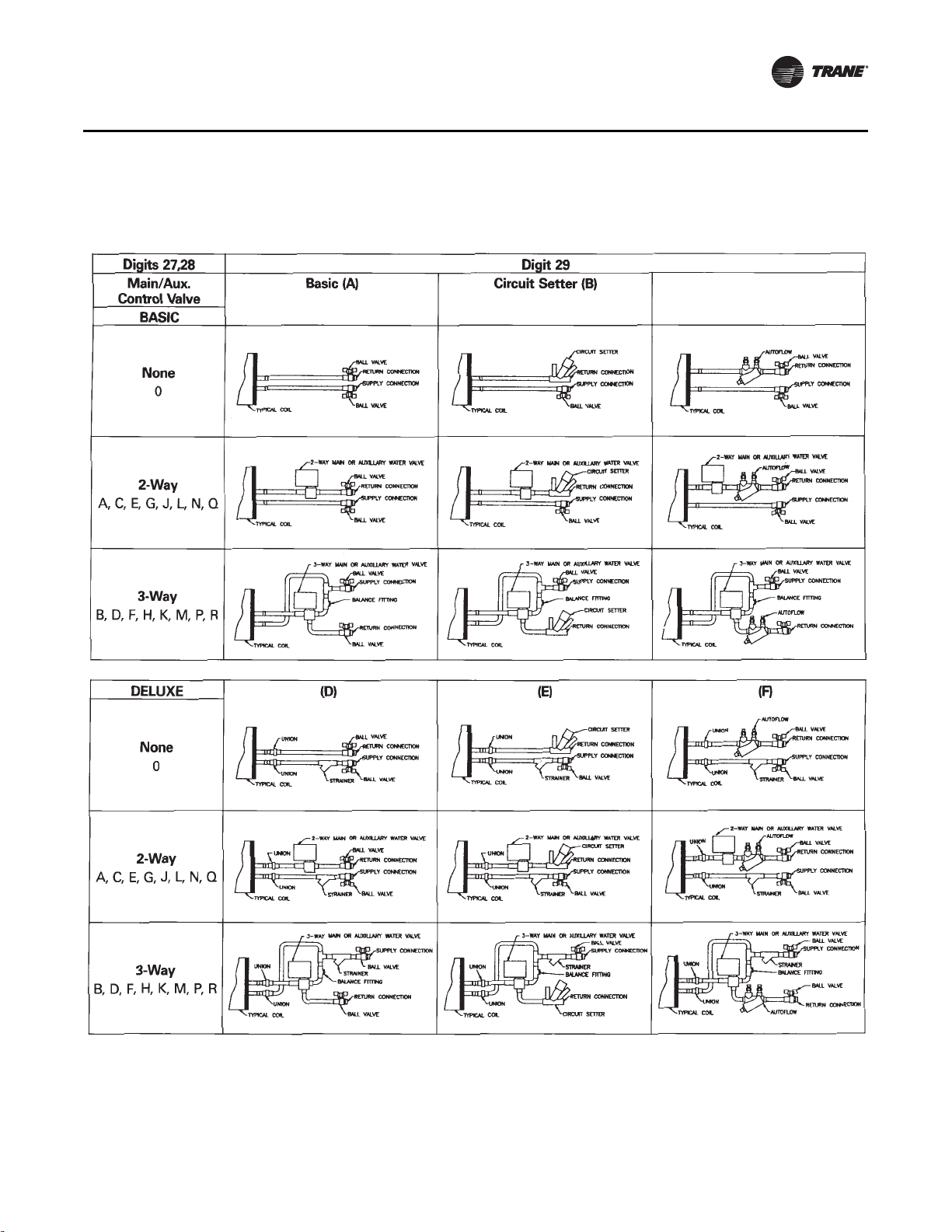
Digit 29 - Piping Packages
0=None
A = Basic Ball Valve supply and
Return
B = Basic Ball Valve Supply/Manual
Circuit Setter
C = Basic Ball Valve Supply and
Return w/Auto Circuit Setter
D = Deluxe Ball Valve Supply and
Return
E = Deluxe Ball Valve Supply/Manual
Circuit Setter
F = Deluxe Ball Valve Supply and
Return w/Auto Circuit Setter
Digit 30 - Control Type
A = Fan Speed Switch
E = Tracer ZN010
F = Tracer ZN510
G = Tracer ZN520
H = Customer Supplied Terminal
Interface
J = Tracer UC400, Single Zone VAV
Digit 31 - Control Option
D = Unit-Mounted Fan Mode Switch
K = Wall-Mounted Fan Mode Switch
V = Unit-Mounted Fan Speed Switch
w/Setpoint Dial Zone Sensor
W = Wall-Mounted Fan Speed Switch
w/Setpoint Dial Zone Sensor
X = Unit-Mounted Fan Speed Switch
w/Wall-Mounted Setpoint Dial
Zone Sensor
Y = Unit-Mounted Fan Speed Switch
& Wall-Mounted Setpoint Dial
w/Comm.
Z = Unit-Mounted Fan Speed Switch,
On/Cancel, Setpoint Dial
w/ Comm.
1 = Wall-Mounted On/Cancel
w/ Comm.
2 = Wall-Mounted Fan Speed Switch,
Setpoint Dial, On/Cancel
w/ Comm.
0 = Without Control Option
3 = Unit-Mounted Low Voltage Fan
Speed Switch (Off /Hi /Med /Low)
4 = Wall-Mounted Digital Zone
Sensor (OALMH, Setpoint,
On/Cancel, Comm Jack)
5 = Wall-Mounted Digital Zone
Sensor (On/Cancel, Comm Jack)
6 = Wireless Zone Sensor
7 = Wireless Display Sensor, Unit-
Mounted Receiver
Digit 32 - Not Used
0
Digit 33 -FLA Motor Option
0 = Standard FLA ECM Mode
A = Reduced FLA ECM Mode
Digit 34 - Future Control
Functions
0=None
Digit 35 - Control Function #3
0=None
Digit 36 - Control Function #4
0=None
Digit 37 - Control Function #5
0=None
Digit 38 - Control Function #6
0=None
Digit 39 - Projection Panels and
Falsebacks
0 = None
A = 5/8” Standard Recessed Panel
(Vertical Recessed Units Only)
B = 2” Projection Panel
C = 2.5” Projection Panel
D = 3” Projection Panel
E = 3.5” Projection Panel
F = 4” Projection Panel
G = 4.5” Projection Panel
H = 5” Projection Panel
J = 5.5” Projection Panel
L = 2” Falseback
K = 6” Projection Panel
M = 3” Falseback
N = 4” Falseback
P = 5” Falseback
Q = 6” Falseback
R = 7” Falseback
T = 8” Falseback
Digit 40 - Main Autoflow gpm
A= 0.5 H=3.5
B = 0.75 J = 4.0
C=1.0 K=4.5
D= 1.5 L= 5.0
E=2.0 M=6.0
F=2.5 N=7.0
G= 3.0 P = 8.0
Digit 41 - Not Used
0
Digit 42 - Subbases
0 = None
A = 2” Subbase
B = 3” Subbase
C = 4” Subbase
D = 5” Subbase
E = 6” Subbase
F = 7” Subbase
Digit 43 - Recessed Flange
0 = None
A = Recessed Flange
Digit 44 - Wall Boxes
0 = None
A = Anodized Wall Box
8 CAB-PRC001-EN
General Data
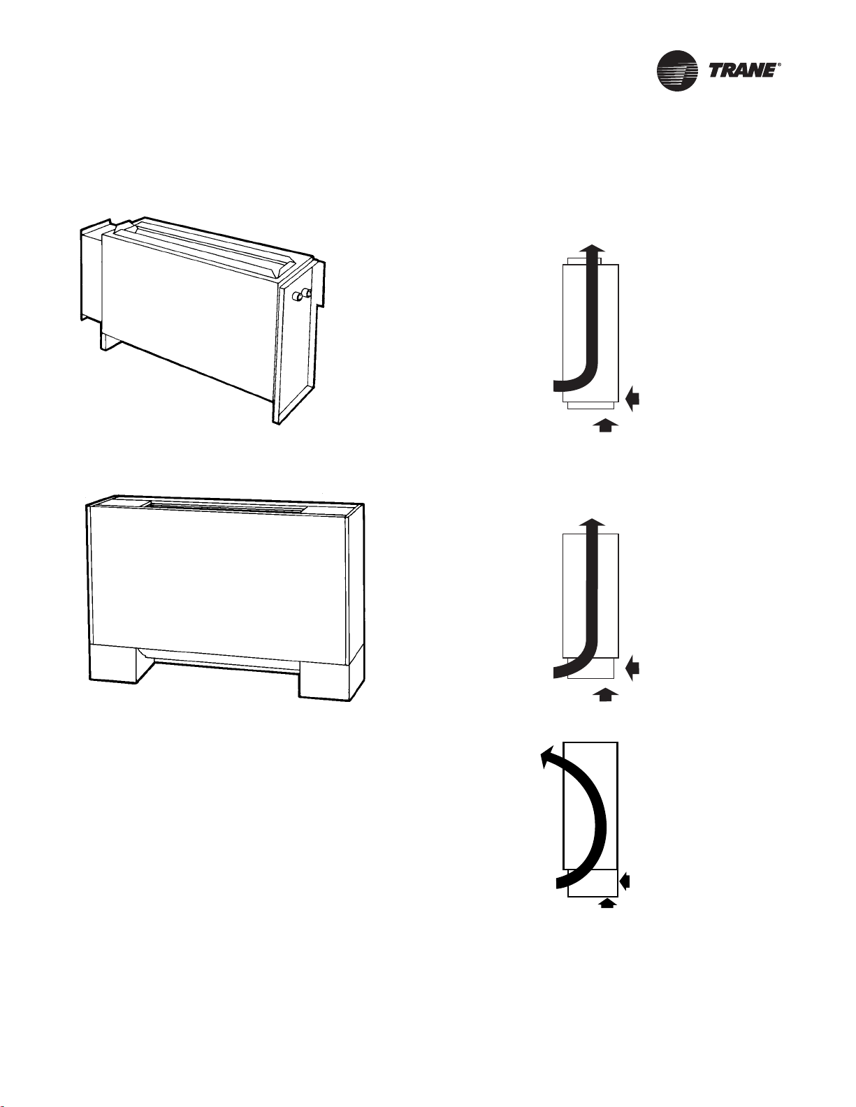
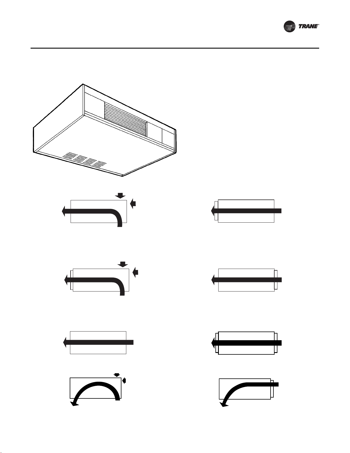
Outlet
Top Duct Collar
Fresh Air
Bottom or Back
Inlet
Front Toe Space
Outlet
Top Quad Grille, Top Bar Grille
Fresh Air
Bottom or Back
Inlet
Front Toe Space,
Front Bar Grille
Outlet
Front Stamped Louver
Fresh Air
Bottom or Back
Inlet
Front Toe Space,
Front Bar Grille
Model A, Vertical Concealed
Model B, Vertical Cabinet
CAB-PRC001-EN 9
General Data
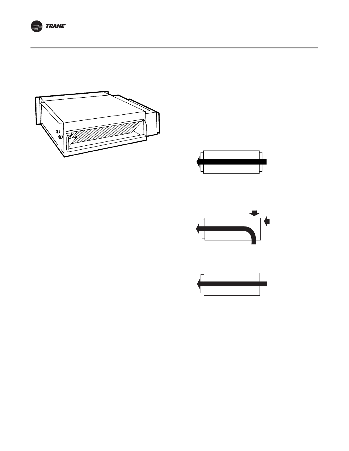
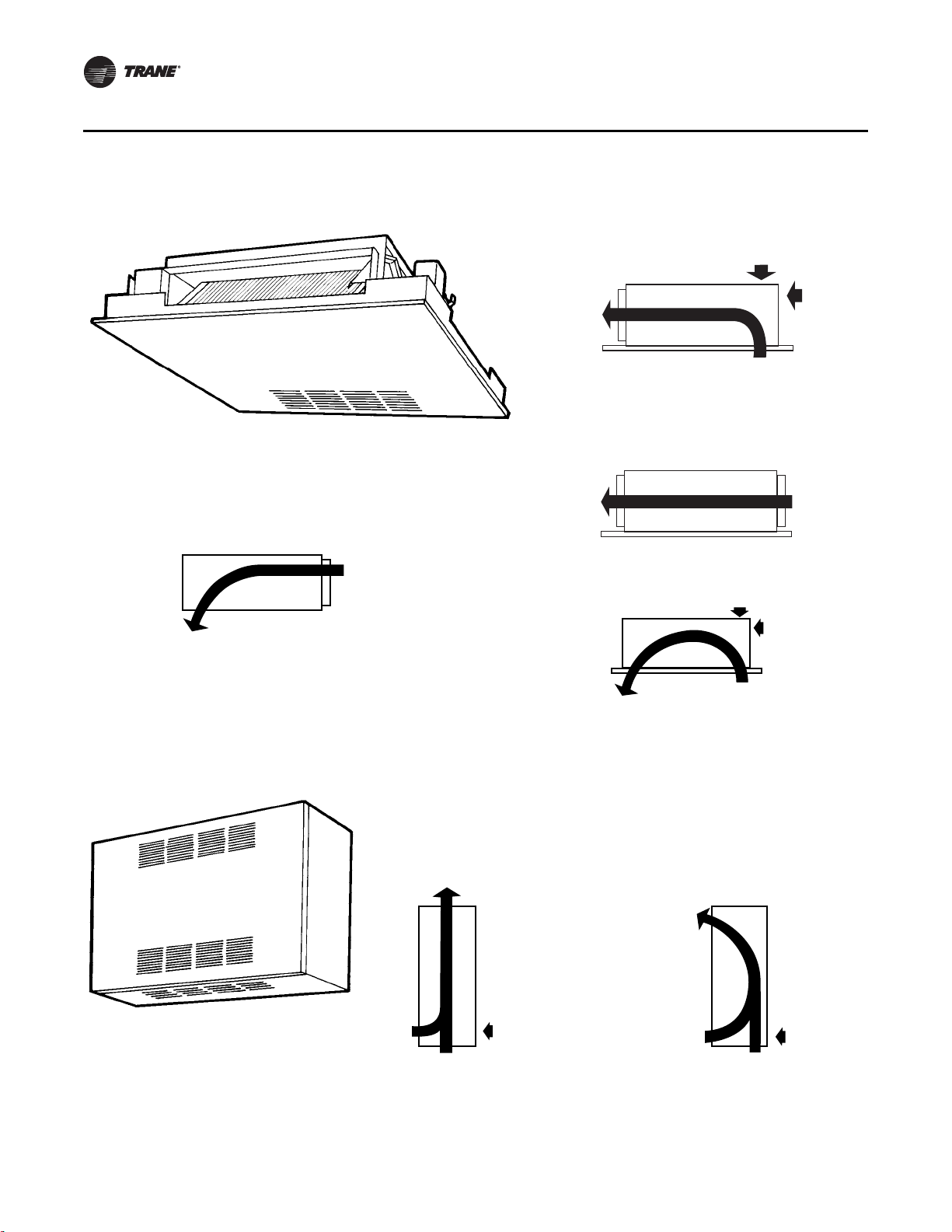
Outlet
Front Duct Collar
Inlet
Back Duct Collar
Fresh Air
N/A
Outlet
Front Duct Collar
Outlet
Front Duct Collar
Fresh Air
Top or Back
Inlet
Bottom Toe Space
Fresh Air
N/A
Inlet
Open Return
No Filter
Model C, Horizontal Concealed
10 CAB-PRC001-EN
Model D, Horizontal Cabinet
Fresh Air
Top or Back
Fresh Air
Top or Back
Fresh Air
N/A
Fresh Air
N/A
Fresh Air
N/A
Fresh Air
N/A
Inlet
Bottom Stamped
Louver
Inlet
Bottom Stamped
Louver
Inlet
Back Stamped
Louver
Inlet
Back Stamped
Louver
Inlet
Back Duct
Collar
Inlet
Back Duct
Collar
Outlet
Front Quad
Grille, Front Bar Grille
Outlet
Front Duct Collar
Outlet
Front Quad
Grille, Front Bar Grille
Outlet
Front Quad
Grille, Front Bar Grille
Outlet
Front Duct Collar
Outlet
Front Duct Collar
Fresh Air
Top or Back
Fresh Air
N/A
Outlet
Bottom Stamped
Louver
Outlet
Bottom Stamped
Louver
Inlet
Bottom Stamped
Louver
Inlet
Back Duct
Collar or
Stamped
Louver
General Data
CAB-PRC001-EN 11
General Data
Fresh Air
Top or Back
Outlet
Front Duct Collar
Inlet
Bottom Stamped
Louver
Outlet
Front Duct Collar
Fresh Air
N/A
Inlet
Back Duct
Collar
Fresh Air
Top or Back
Outlet
Bottom Stamped
Louver
Outlet
Bottom Stamped
Louver
Inlet
Bottom Stamped
Louver
Inlet
Back Duct
Collar
Outlet
Top Quad Grille,
Top Bar Grille
Fresh Air
Back
Inlet
Bottom & Front
Stamped Louver
Outlet
Front Stamped
Louver
Fresh Air
Back
Inlet
Bottom & Front
Stamped Louver
Model E, Horizontal Recessed
Model F, Vertical Wall Hung Cabinet
12 CAB-PRC001-EN
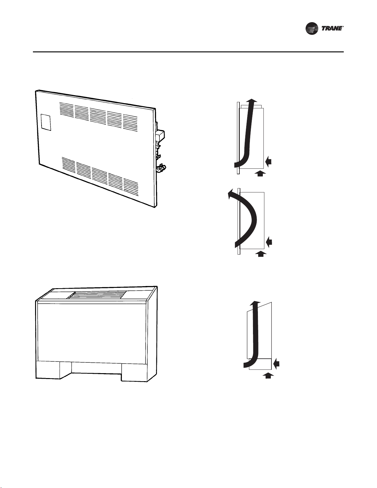
Model H, Vertical Recessed
Outlet
Top Duct Collar
Outlet
Front
Stamped
Louver
Fresh Air
Bottom or Back
Fresh Air
Bottom or Back
Inlet
Front Stamped
Louver
Inlet
Front
Stamped
Louver
Outlet
Top Quad Grille, Top Bar Grille
Fresh Air
Bottom or Back
Inlet
Front Toe Space,
Front Bar Grille
General Data
Model J, Vertical Cabinet Slope Top
CAB-PRC001-EN 13
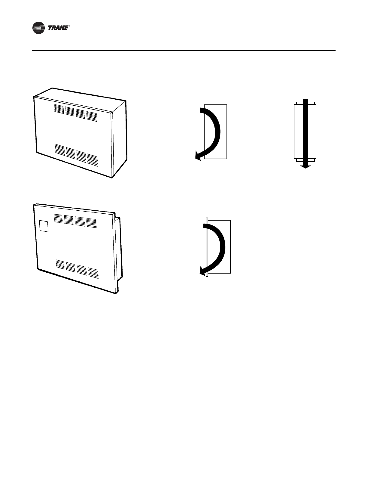
General Data
Inlet
Front Stamped
Louver
Outlet
Front Stamped
Louver
Inlet
Top Duct
Collar
Outlet
Top Duct
Collar
Inlet
Front Stamped
Louver
Outlet
Front Stamped
Louver
Model M, Inverted Vertical Concealed
Model N, Inverted Vertical Recessed
14 CAB-PRC001-EN

General Data
Table 1. Force-Flo cabinet heater general data
Unit Size 02 03 04 06 08 10 12
Coil Data
Face Area-ft
LxDxH-in.
Volume-gal.
Fins/ft
Fan/Motor Data
Fan Quantity 1112233
Size-Dia.” x Width” 6.31x4 6.31x6.5 6.31x7.5 6.31x6.5 6.31x7.5 (1) 6.31x7.5 6.31x7.5
Motor Quantity 1111122
Filter Data
1” TA and Pleated Media
Quantity 1111111
Size-in. 8-7/8x19-1/8 8-7/8x19-1/8 8-7/8x24-1/8 8-7/8x33-5/8 8-7/8x42-1/8 8-7/8x61-1/8 8-7/8x61-1/8
1” Fresh Air Filter (Only on Cabinet Styles D, E, and H with Bottom Return and Fresh Air Opening)
Quantity 1111111
Size-in. 5-1/2x19-1/8 5-1/2x19-1/8 5-1/2x24-1/8 5-1/2x33-5/8 5-1/2x42-1/8 5-1/2x61-1/8 5-1/2x61-1/8
2
0.80.81.11.62.13.23.2
2-Row 15x1.7x8 15x1.7x8 20x1.7x8 29.5x1.7x8 38x1.7x8 57x1.7x8 57x1.7x8
3-Row 15x2.6x8 15x2.6x8 20x2.6x8 29.5x2.6x8 38x2.6x8 57x2.6x8 57x2.6x8
4-Row 15x3.5x8 15x3.5x8 20x3.5x8 29.5x3.5x8 38x3.5x8 57x3.5x8 57x3.5x8
1-Row 0.06 0.06 0.08 0.11 0.14 0.21 0.21
2-Row 0.12 0.12 0.15 0.22 0.28 0.42 0.42
3-Row 0.18 0.18 0.23 0.33 0.42 0.62 0.62
4-Row 0.24 0.24 0.30 0.44 0.56 0.83 0.83
2-Row 144 144 144 144 144 144 144
3-Row 144 144 144 144 144 144 144
4-Row 144 144 144 144 144 144 144
(2) 6.31x6.5
CAB-PRC001-EN 15
General Data
Table 2. Cabinet heater air flow
ESP
FD Motor High Static Motor
Unit Size Coil
02 2R144 246 344 314 283 251
3R144 242 352 319 284 249
4R144 222 326 295 263 230
03 2R144 313 410 380 350 319
3R144 309 391 358 324 290
4R144 276 360 330 299 267
04 2R144 381 446 410 373 336
3R144 365 544 506 467 427
4R144 340 506 470 434 397
06 2R144 609 757 700 642 582
3R144 604 880 824 766 707
4R144 557 812 760 706 652
08 2R144 790 1014 950 885 819
3R144 724 992 927 861 794
4R144 676 930 870 808 745
10 2R144 1015 1284 1199 1113 1024
3R144 1052 1456 1360 1262 1162
4R144 988 1366 1276 1183 1089
12 2R144 1105 1424 1330 1234 1134
3R144 1074 1514 1419 1320 1219
4R144 993 1421 1330 1238 1144
Note: This is data is based on horizontal concealed model only, with duct inlet, duct outlet and no filter, dry coil, all voltages
except 208 V.
0.05 0.1 0.2 0.3 0.4
Electric Heat
All Force-Flo cabinet heaters, except inverted models M and N, are available with electric heating
coils as a standard option.
Coil Construction
Electric heat coils are open wire type with a nickel chromium element design.
Power Supply
Units have single-point power since the electric heating elements operate on line voltage. Electric
heat is available as 208/60/1, 230/60/1, 277/60/1, 208/60/3, or 480/60/3. Electric heat coils operate on
the same voltage as the unit, except for units with 480/60/3 electric heat. In this case, the unit
operates at 277/60/1, thus requiring a 4-wire supply. All fans and motors are single phase. In
addition, all control options are 24-volt, utilizing a factory-installed transformer.
Power Supply Location
All electric heat cabinet heaters have a terminal block for main power on the unit’s right-hand side.
Control Type
Single-stage electric heat units are controlled by either Tracer UC400, ZN010, ZN510, or ZN520
control options. Two-stage electric heat is controlled by the Tracer UC400, ZN520 only. Both
control options use PWM (pulse-width modulation) outputs to calculate the electric heat output
16 CAB-PRC001-EN

based on the capacity request and the electric heat cycles per hour. For example, if the electric heat
cycles per hour is configured for six cycles (as Trane recommends) the controller bases the output
on or off time on six 10-minute periods. If the capacity request is 40 percent, the controller controls
the electric heat output on for approximately four minutes each period.
Safety Features
• Fan/valve operation to ensure safe operation and to ensure that two modes of heat are not
operating simultaneously.
• All Force-Flo units with standard electric
• Units require only a single-point electrical connection.
• All electric heating coils are interloc
operation is only possible when the fan is running.
• Each unit has a transformer, eliminating the nee
transformer.
• Unit-mounted quiet magnetic relays are supplied on all unit voltages.
• A line-break high temperature cutout
elements to de-energize the electric heat in the event of an overheat condition.
Factory-Installed Piping Packages
Force-Flo cabinet heaters have standard piping packages available as a factory built and installed
option. Factory built assures all piping packages are fully tested under water for leaks and are built
within strict tolerances. Factory-installed means that supply and return pipes are the only field
connections required. The installer doesn’t have to sweat connect piping packages onto coil
connections in a tight end pocket. Field connections are brought to a point near the exterior of the
unit for easy access.
General Data
heat are UL listed.
ked with the fan motor switch. Therefore, electric heat
d for field installation of a stepdown
with automatic reset is provided as an integral part of the
Piping Package Components
Force-Flo piping packages consist of a variety of components for each application. The following
section provides a detailed description of the piping components. Following this section are
additional illustrations and specifications.
Piping System/Placement
Factory piping packages are available with right or left hand connections. A simple coil connection
(a unit without a piping package) is also available in either a right or left hand configuration for
those applications requiring field piping.
Interconnecting Piping
Interconnecting piping refers to the copper piping that attaches the coil connections and all other
components such as control valves, end valves, etc. Piping is 1/2” nominal OD copper and extends
near the unit exterior to one inlet and one outlet connection.
Deluxe or Basic Piping Package
The basic piping package includes only the main components of the piping package:
interconnecting piping, control valves, and end valves.
The deluxe piping package also includes a strainer on the entering water pipe and unions at the
coil connections along with the basic components listed above. The strainer body is cast brass
construction, with a stainless steel mesh strainer that is easily removed for cleaning. The unions
are forged brass construction and close with a minimum amount of effort.
CAB-PRC001-EN 17

General Data
End Valves
Each piping package includes a ball valve for the entering water pipe and one of the following end
valves on the leaving water pipe: ball valve, manual circuit setter, or an auto circuit setter. These
valves serve as the field connection points on all Force-Flo piping packages.
Ball Valves
Ball valves, also known as stop or end valves, allow the unit to be cut off for service purposes. These
valves have a two-inch handle that rotates 90° to a fully open position. The valve body is cast brass,
and the ball is polished brass with a Teflon
the entering and leaving water pipes.
®
seat. Ball valves are available as end valves on both
Manual Circuit Setter
In lieu of a ball valve on the leaving water pipe, a manual circuit setter, also known as a manual flow
control valve, acts as both a flow setting device and a stop valve. This valve allows water flow
through the cabinet heater to be set quickly and accurately.
The manual circuit setter includes Schrader ports in the valve body. These ports are used to
measure the pressure drop across the valve. This pressure drop can be compared to factory
supplied curves that relate the pressure drop to a specific flow rate. This valve also has a memory
stop that helps find the correct setting quickly.
Auto Circuit Setter
An auto circuit setter is an automatic flow control device available on the leaving water pipe. The
auto circuit setter includes a cartridge within the valve body that is sized to allow a specific flow
rate through the coil. This valve sets flow through the coil without any action required by a system
piping balancer. The auto circuit setter is available on the leaving water pipe with a ball valve.
The auto circuit setter also includes two P/T’s plugs in the valve body to allow measurement of the
pressure drop temperature through the valve.
Control Valves
Piping packages are available with or without control valves. All control valve options are factory
mounted and wired to the Force-Flo unit controls.
Tw o - Wa y / Tw o - P o s i t i o n Va l v e s
These valves will either fully open or close in response to a 24 Vac signal from the Tracer controller.
Control valves are direct-acting valves. The control valve is factory mounted in the leaving water
pipe downstream of the coil. Always use some means of relieving pump head pressure with twoway valve applications. Normally open or normally closed valves are available.
Three-Way/Two-Position Valves
These valves will either allow full water flow through the coil or divert the flow through a bypass
line. The valves respond to a 24 Vac signal from the Tracer controller. Control valves are direct
acting valves. All three-way valve packages include a balance fitting in the bypass line to allow flow
balancing in the bypass position. Three-way valves are factory mounted in the leaving water pipe
downstream of the coil. Normally open or normally closed valves are available.
Two-Way Modulating Valves
These valves modulate the water flow through the coil in response to a signal from the Tracer
controller. Modulating valves are three-wire floating point equal percentage valves, and are factory
mounted in the leaving water pipe downstream of the coil.
Three-Way Modulating Valves
These valves modulate the water flow through the coil in response to a signal from the Tracer
controller. Three-way valves allow water that is directed through the coil to mix with water directed
through the bypass line. This mixture exits through the leaving water pipe. Modulating valves are
18 CAB-PRC001-EN
three-wire floating point equal percentage valves, and are factory mounted in the leaving water
Auto Flow Valve (C)
pipe downstream of the coil.
Figure 1. Piping package options
General Data
CAB-PRC001-EN 19
General Data
Selecting the Correct Modulating Valve Size
Modulating valves are available in any of four port sizes: 0.7, 1.5, 2.5 or 4.0 Cv (coefficient of flow
values). The coefficient of flow is defined as the volume of water flow through a control valve in
the fully open position with a 1 psig differential across the valve. Calculate the coefficient of flow
using the formula:
Cv = Q/square root ΔP where:
Cv = flow coefficient
Q = flow rate (gpm)
ΔP = pressure drop across the valve or coil (psig).
For good control, the valve Cv should be approximately equal to the Cv of the water coil.
Modulating Valve Selection Example
Assume a size 06 vertical cabinet heater is selected to operate at the following conditions:
EWT = 180°F
LWT = 1 5 0°F
EAT = 70°F
The coil selection is a four-row coil. Select the best modulating valve size for this unit.
1. Find the ΔP across the water coil. Refer to the ARI performance table to determine the ΔP across
the water coil or use the Trane Official Product Selection System, TOPSS™, selection program.
The water pressure drop is found to be 5.7’ of water at a flow rate of 3.59 gpm. This converts
to a pressure drop of 2.47 psig (1.0 feet of water = 0.4328 psig.)
2. Calculate the Cv of the water coil.
Cv = gpm/Square root ΔP.
3.59/Square root 2.47
Cv =
Cv = 2.29
Therefore, select the 2.5 Cv valve because it is closest to the water coil.
Ta b l e 3 and Table 4, p. 21 illustrate possible valve selections at ARI conditions for horizontal
concealed units with a high static motor and vertical cabinet units with a free discharge motor. For
other applications, use TOPSS to determine flowrate and make calculations using the formulas
above.
Table 3. Modulating valve selections for horizontal concealed units, high static motor, 70°F EAT,
180°F EWT, 30°F ΔT
Unit Size Coil gpm Coil WPD Coil Cv Valve Cv
02 2-Row 1.19 6.0 0.74 0.7
3-Row 1.52 13.8 0.62 0.7
4-Row 1.59 3.8 1.24 1.5
03 2-Row 1.53 10.3 0.72 0.7
3-Row 1.82 4.3 1.33 1.5
4-Row 1.98 6.2 1.21 1.5
04 2-Row 1.73 3.3 1.45 1.5
3-Row 2.57 9.1 1.29 1.5
4-Row 2.81 13.4 1.17 1.5
06 2-Row 2.87 9.9 1.39 1.5
3-Row 3.96 5.9 2.48 2.5
4-Row 4.37 8.2 2.32 2.5
20 CAB-PRC001-EN
General Data
Table 3. Modulating valve selections for horizontal concealed units, high static motor, 70°F EAT,
180°F EWT, 30°F ΔT (continued)
Unit Size Coil gpm Coil WPD Coil Cv Valve Cv
08 2-Row 3.71 4.7 2.60 2.5
3-Row 4.74 9.1 2.39 2.5
4-Row 5.22 12.7 2.23 2.5
10 2-Row 4.71 8.1 2.52 2.5
3-Row 6.50 18.1 2.32 2.5
4-Row 7.13 25.3 2.15 2.5
12 2-Row 5.48 11.4 2.47 2.5
3-Row 7.19 14.5 2.87 2.5
4-Row 7.83 10.5 3.67 4.0
Table 4. Modulating valve selections for vertical cabinet units, free discharge motor, 70°F EAT,
180°F EWT, 30°F ΔT
Unit Size Coil gpm Coil WPD Coil Cv Valve Cv
02 2-Row 1.06 4.8 0.74 0.7
3-Row 1.31 10.5 0.61 0.7
4-Row 1.34 2.8 1.22 1.5
03 2-Row 1.40 8.8 0.72 0.7
3-Row 1.70 3.8 1.33 1.5
4-Row 1.81 5.3 1.20 1.5
04 2-Row 1.71 3.2 1.45 1.5
3-Row 2.12 6.4 1.27 1.5
4-Row 2.28 9.1 1.15 1.5
06 2-Row 2.70 8.9 1.38 1.5
3-Row 3.31 4.2 2.46 2.5
4-Row 3.59 5.7 2.29 2.5
08 2-Row 3.39 4.0 2.58 2.5
3-Row 4.11 6.9 2.38 2.5
4-Row 4.45 9.4 2.21 2.5
10 2-Row 4.32 6.8 2.52 2.5
3-Row 5.55 13.4 2.30 2.5
4-Row 6.00 18.3 2.13 2.5
12 2-Row 4.99 9.6 2.45 2.5
3-Row 6.10 10.5 2.86 2.5
4-Row 6.48 7.3 3.65 4.0
CAB-PRC001-EN 21
 Loading...