

Page 1
Architectural
Hydronic Wall Fin
FIN-PRC004-ENOctober 2001
Page 2
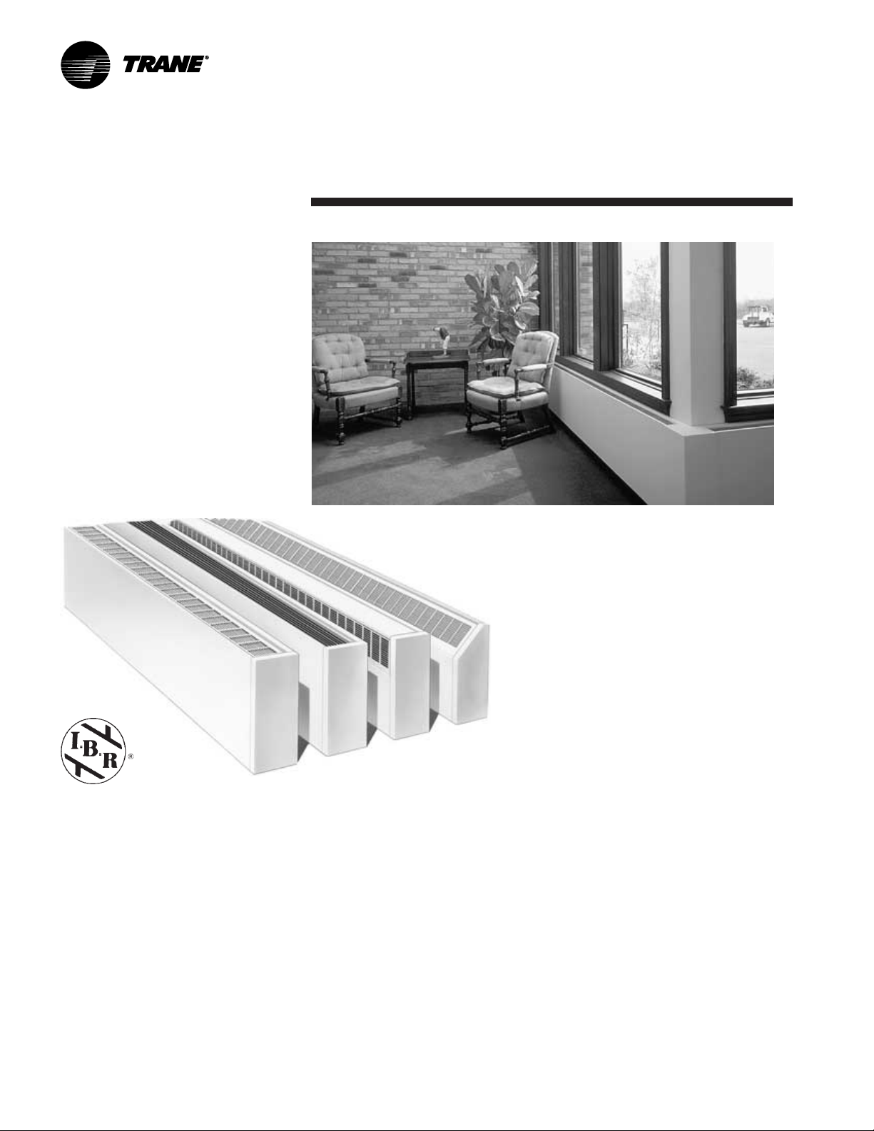
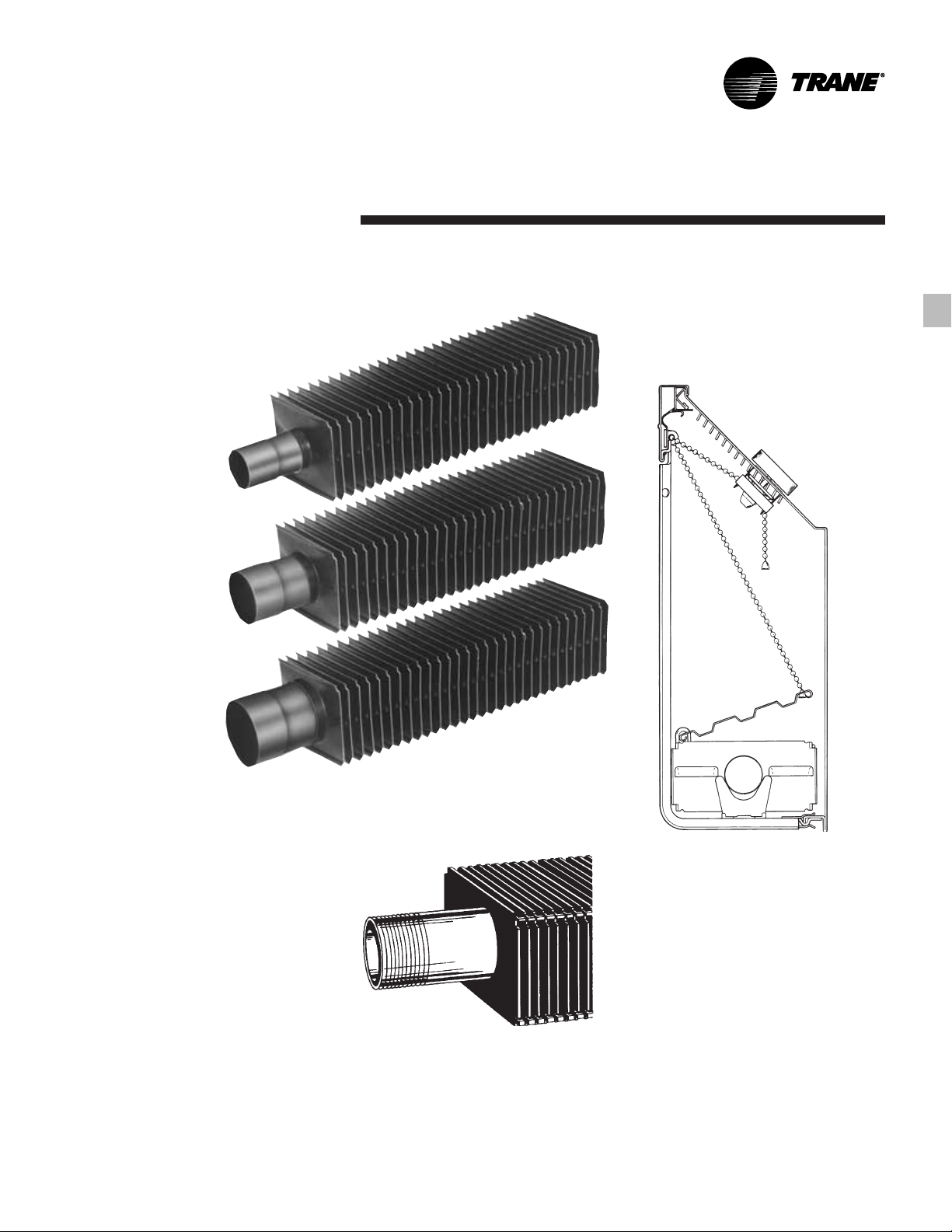
A Complete Line of Wall Fin
Trane architectural wall fin is ideal for
heating modern commercial,
institutional or industrial buildings.
Attractive styling and wide application
flexibility allow wall fin cabinet designs
to be used for virtually any application.
Available for hydronic or steam heating,
Trane wall fin can also be used in
combination with convectors for smaller
areas, allowing for the use of one source
when designing a radiation heating
system. (See FIN-DS-2 for convector
applications.)
Trane Wall Fin — Simply the Best
Wall fin effectively meets the heating
needs of long, open areas. It counters
cold air downdrafts common to
expansive glass areas used in many of
today’s most prestigious buildings.
Provides continuous heat along room
•
perimeter.
Allows removal of any unit panel for
•
service accessibility.
The front panel never touches the wall
•
— only Trane’s exclusive mounting
strip.
The front panel can be raised or
•
removed without disturbing the unit or
damaging wallpaper, paint or the
plaster seal.
Operates quietly because there are no
•
moving parts.
Type T
Features
and Benefits
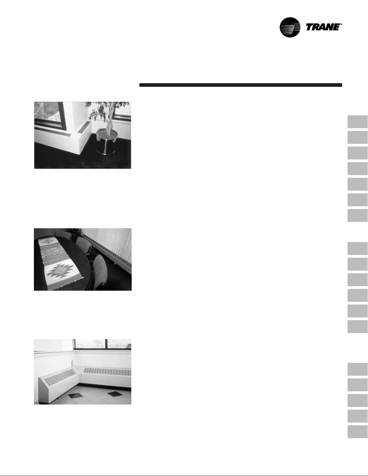
An effective heating system for any office. Attractive styling that blends with any
architectural design.
Type S
Type F
Type TA
Controls with the damper or valve
•
individually.
Blends well with any decor.
•
Works effectively with cooling-only
•
VAV and heat recovery systems.
Includes 14 or 16-gauge front panels.
•
Unit vent draft barrier enclosures.
•
Pipe enclosures for use with ForceFlo
•
and Fan Coil Units.
Wall Fin
I=B=R Certified Ratings for Trane Wall
Fin
The I=B=R symbol is the registered
trademark of the Hydronics Institute
which tests and rates in strict accordance
with published standard wall fin
elements and elements with enclosures.
The wall fin heating units must conform
to appropriate test standards to have
certified I=B=R ratings.
Why Hydronics?
Besides the reliability of equipment
ratings, and the well established
reliability of hydronic accessories, there
are many good reasons why hydronic
systems have long been recognized as
the standard method for providing
indoor comfort.
Hydronic heating, whether steam or hot
water, provides positive, controlled
circulation of the heating medium.
Systems are basically self-balancing, and
in larger, more complicated heating
systems, balancing is positively
controlled by familiar valves and
thermostats.
The life of some hydronic equipment
may be measured in decades; some
existing boilers are more than fifty years
old. In addition to the high efficiency of
boilers (some over 85%) the losses
through the distribution system are
extremely low on modern installations.
Temperature control is close to ideal with
hydronics. Any well-designed system
can provide excellent comfort, without
drafts or sharp swings in temperature.
The flexibility of hydronic installations
permits a variety of piping
arrangements, simple or sophisticated
controls, and a large choice of room
distribution units for all comfort
applications.
© 2001 American Standard Inc. All rights reserved.
FIN-PRC004-EN
Page 3
Contents
Architecural Wall Fin
Features and Benefits
Application Considerations
Selection Procedure
Performance Data
Dimensional Data
Options
Mechanical Specifications
Security Wall Fin
Features and Benefits
Accessories
Model Number Description
Performance and General Data
2
6
7
14
41
54
56
74
75
76
77
FIN-PRC004-EN
Dimensional Data
Mechanical Specifications
Hydronic Light Commercial
Slope Top Wall Fin — Model 11S
Features and Benefits
Performance and General Data
Dimensional Data
Cover and Accessory Layout
Mechanical Specifications
85
91
93
96
98
100
101
3
Page 4
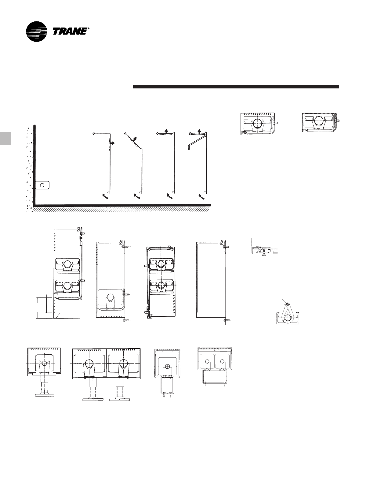
Features and
Benefits
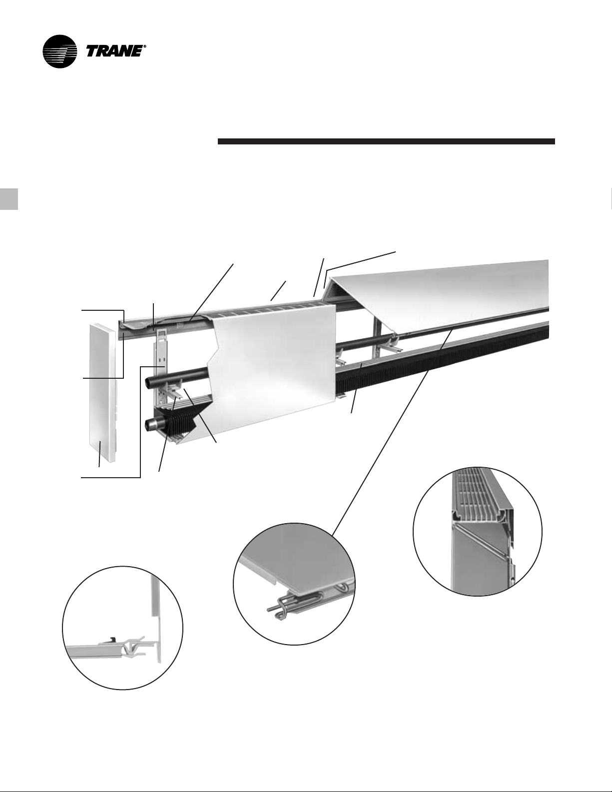
A simple installation designed to last
without visible fasteners — Trane’s
exclusively designed mounting strip
makes it possible.
Cabinet
enclosures
and
accessory
panels
hinge-lock
easily into
mounting
strip.
Roll-formed
indentation
runs full
length of
mounting
strip for
easy bolt
hole
location.
Ribbed steel
enclosure
brackets
provide
element
support base
and brace the
Mounting strip keys entire
installation, attaches to any
wall, and assures the tightest
fit possible — even against
the most imperfect wall.
End Panel
Element/pipe
supports
position in slots
in the enclosure
bracket to allow
two-tier
element and
pipe
installation.
Curved rectangular
metal washers to
assure tight fit against
the wall.
Serves as wall
panel stop.
Cradle and nylon cradle
guides assure exact element
location and allow element
cradles to slide freely and
noiselessly.
Serves as plaster
stop for semirecessed
installations.
Rigid element damper
provides heat
modulation.
Roll-formed front panels hinge
invisibly into the mounting strip.
Locking clip slides over panel lip to hold it
securely to bracket.
Deluxe unit with extruded grille. The grille is
separate and hinges into the mounting strip.
Panel clip and slide bolt fastener for front
panel alignment are hidden from view.
FIN-PRC004-EN4
Page 5
Features and
Benefits
Hydronic Heating Elements — Copper/
Aluminum and Steel
Copper-Aluminum Elements
3
/4”, 1” and 1 1/4” (19 mm, 25 mm and 32
mm) Copper Tubes With 40, 50 or 58
Aluminum Fins per foot (131, 164 190
per meter).
3
/4” (19 mm)
1” (25 mm)
1
/4” (32 mm)
1
Positive Temperature Control
Efficient element-mounted damper.
•
Reduces unit capacity by 70 percent.
•
Has jam-proof bead chain control
•
system.
Control knob is mounted on the outlet
•
grille.
Steel Elements — Standard options
feature 1
steel fins per foot (171 per meter).
1
1
/4” (32 mm) steel tube with 52
1
/4” (32 mm)
For Models S, F, T & TA
Elements available in copper-
•
aluminum or steel.
Elements are efficient and long lasting.
•
Element tubes mechanically expanded
•
into fin collars.
Fin collars provide even and positive
•
spacing for even air distribution.
The mechanical bond assures an
•
efficient and durable element
assembly.
Fins cannot work loose.
•
5FIN-PRC004-EN
Page 6
Application
Considerations
A Heating System and Style to Suit Any Application
Wall Mounted
T
Top Outlet
Top Outlet
Extruded
Front Outlet
Wall Mounted Cabinet Options
3
/8”
3
(86 mm)
FS
Slope Top
Outlet
With
Grille
TA
Type E Type X
Enclosure styles meet the heating needs
of long, open areas in any interior.
Wall-mounted wall fin enclosures
•
available in depths of four and six
inches (102 mm, 152 mm).
Enclosure depth is determined by the
•
type of element to be used.
See pages 13 through 43 and Tables
•
PD-1 through PD-25 for details.
Front inlet grilles.
•
Bottom inlet grilles.
•
Inverted enclosures for styles S, F and
•
T enclosures only.
Tamperproof fastener option.
•
Pipe Enclosures
•
Tamperproof
Fastener
Ceiling Mounted
Type CS
1
/2” (13 mm) Dia. Mtg. Hole
4 1/2”
(114 mm)
Front Inlet Grille
Floor Mounted
Type E3
Continuous
Sheet Metal
Angle
Type E3-2W
Inverted Enclosure
Type E3A-1W
Pipe EnclosureBottom Inlet Grille
Type E3A-2W
Ceiling-mounted wall fin enclosures
•
available in depths of four and six
inches (102 and 105 mm).
See pages 13, 14, 15 and 49.
•
Pedestal wall fin enclosures available
•
with one or two wide elements.
See pages 36, 37, 42, 53, 54, 55, 56, 57
•
and 58 and Tables PD-24, PD-25, M-1,
M-2, M-3, M-4 and M-5.
FIN-PRC004-EN6
Page 7

Selection
Procedure
Hydronic/Steam Wall Fin
Selection
Hot Water Systems
The capacity rating of wall fin in a hot
water heating system depends on the
difference between average water
temperature and entering air
temperature, and on the velocity at
which water is circulated through the
tube. The effect of water velocity on the
capacity rating is appreciable (see Chart
S-1) and should be taken into account
when selecting wall fin. Following are
example selections for hot water
systems.
Hot Water Systems
Example 1
Assume a two-pipe system is being used
with 180°F average water temperature,
20°F temperature drop and 65°F entering
air temperature. Assume a calculated
heat loss of 20,000 Btu, for which one
row of 1 1/4” steel element in a Type 12S
enclosure is desired.
From Chart S-1, reading from 20,000 Btu
(under 20°F temperature drop) across to
1
/4” steel element and down, indicates
a 1
a water velocity of approximately .45 ft/
sec. The water velocity correction factor
corresponding to .45 ft/sec is .920. The
radiation is selected so that it would
deliver
20,000 Btu (calculated heat loss)
0.920 (velocity correction factor)
or 21,739 Btu if the water velocity were 3
ft/sec. It will then deliver the required
20,000 Btu at the actual water velocity of
.45 ft/sec.
1
From Table PD-8, the output of 1
steel, Series 52 element in a Type 12S
enclosure is (looking under 180°F
average water, 65°F entering air) 1060
Btu/lineal foot at 3 ft/sec water velocity.
Wall fin required:
21,739 Btu = 20.5 lineal feet.
1060 Btu/ft
Length Selection — Loop Systems
Example 2
If the unit in Example 1 above was part
of a 100,000 Btu loop with a 20°F drop
(across the entire loop) the water
velocity through the loop would be 2.20
ft/sec and the water velocity correction
factor for all units on this loop would be
approximately .987. For the unit being
considered, the radiation would be
selected to deliver 20,300
20,000
/4”
( .987 )
Btu at 3 ft/sec water velocity.
Steam Systems — Selecting Wall Fin
Lengths
The capacity rating of wall fin in a steam
heating system depends upon the
difference between the steam
temperature and the entering air
temperature. For any steam system, to
establish the lineal feet of wall fin
required: divide the heat loss by the
capacity rating per foot at the steam
system and entering air conditions.
Ratings for 1 psi steam and 65°F
entering air can be found on Tables
PD-1 through PD-21. Ratings for other
steam and air conditions can be
obtained by multiplying the 1 psi —
65°F capacity ratings by the proper
steam correction factor from Table S-2.
Example 1
Assume a steam system with 1 psi
steam and 65°F entering air conditions.
Also assume a 15,000 Btu heat loss for
which a 1” copper-aluminum element 40
fins/foot in a Type 10S enclosure is
desired.
Wall fin required:
15,000 Btu = 13.9 lineal feet.
1080 Btu/ft
Example 2
Assume a steam system with 20 psi
steam and 55°F entering air conditions.
Also assume a 25,000 Btu heat loss for
which 2 rows of 1
element on 9
without a cover. The capacity rating per
lineal foot from Table PD-3 at 1 psi steam
and 65°F entering air is 2120 Btu/ft.
Multiplying this capacity rating by 1.52
(steam correction factor from Table S-2)
gives a rating of 3222 Btu/ft with 20 psi
steam and 55°F entering air.
Wall fin required:
3222 Btu/ft
= 8 lineal feet, 2 rows high.
1
/4” steel, Series 40
1
/2” centers will be used
25,000 Btu
7FIN-PRC004-EN
Page 8
Selection
Procedure
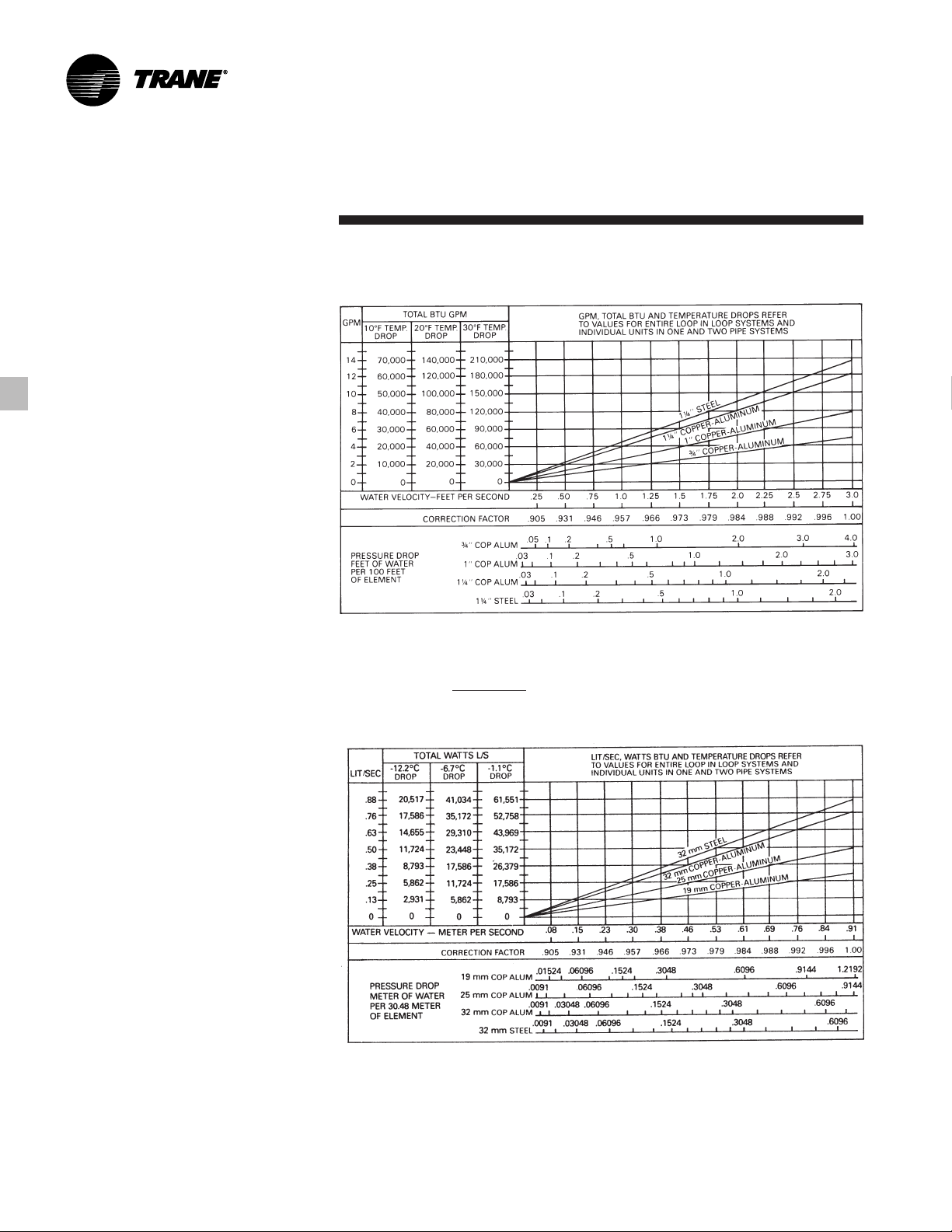
Chart S-1 — Water Velocity Correction
Factors — Pressure Drops ENGLISH
All Catalog Capacities Based On 3.0
Feet Per Second Water Velocity.*
*Correction Factor = .04
Water Velocity
( 3 )
SI
FIN-PRC004-EN8
Page 9

Selection
Procedure
Effect of Temperature Drop On
Fin-Tube Ratings
The effect of temperature drop on heat
output of a wall fin element can be
readily determined. Select the heating
element using average water
temperature (entering water
temperature minus
1
/2 water
temperature drop) and correct for water
velocity as follows:
By use of the relationship,
GPM =
BTU
*500 x Water Temperature Drop
the waterflow rate for a wall fin unit of
the required Btu and at a definite
temperature drop, is easily calculated.
(Many engineers use gallons per minute
as the basis for selecting pipe sizes, since
charts are set up on this basis in the
The heat output of a given wall fin unit
will vary somewhat with different water
velocities, all other conditions being
equal. From Chart S-1, the water velocity
can be found for a wall fin element of the
particular tube size and gpm waterflow
required. The velocity correction factor
can be determined by using Chart S-1.
ASHRAE Guide. Therefore, this would
not be an extra step.)
Table S-1 — Pipe Water Capacities and Quantities Circulated at Velocity of 3* Feet Per Second (.91 m/s)
Nominal Expanded Gals. Per Liters Per Gals./Min. @ 3’ Liters per Sec. Lbs./Hr. @ 3’ Kg/S @ .91 m
Pipe Size ID Linear Ft. Meter Sec. Vel.* @ .91 M/Sec. Vel. Sec. Vel.* Sel. Vel.
3
/4” CA (19 mm) 0.836” (21 mm) .029 .36 5.13 .324 2,555 .322
1” CA (25 mm) 1.073” (27 mm) .047 .58 8.45 .533 4,215 .531
1 1/4” CA (32 mm) 1.311” (33 mm) .070 .87 12.6 .795 6,285 .792
1 1/4” ST (32 mm) 1.40” (36 mm) .080 .99 14.39 .908 7,170 .903
*3 Ft./Sec. (.91 m/Sec) Velocity is Basis for Hot Water Rating Factors Shown in Chart S-1.
Velocity Ft./Sec. =
For quiet operation, a maximum of 5 ft/sec (1.5 m/Sec) velocity is recommended.
Table S-2 — Wall Fin Rating Correction Factors*
Steam Press. Steam Temp. 45°F55°F65°F70°F75°F80°F85°F90°F 100°F 110°F 120°F 130°F 140°F 150°F
PSIG kPa (F) (c) 7°C13°C 18C 21°C24°C27°C29°C32°C38°C43°C49°C54°C60°C66°C
0 0 212.0 100.0 1.19 1.09 0.97 0.92 0.87 0.82 0.77 0.70 0.63 0.54 0.46 0.38 0.31 0.25
.899 6.2 215.0 101.7 1.22 1.11 1.00 0.95 0.90 0.84 0.80 0.75 0.65 0.57 0.48 0.40 0.33 0.26
5 34.5 227.1 108.4 1.34 1.22 1.11 1.05 1.00 0.95 0.90 0.81 0.75 0.66 0.57 0.49 0.41 0.34
10 69.0 239.4 115.2 1.45 1.33 1.22 1.17 1.11 1.05 1.00 0.91 0.85 0.75 0.66 0.58 0.50 0.42
20 137.9 258.8 126.0 1.63 1.52 1.40 1.33 1.28 1.23 1.17 1.07 1.02 0.92 0.82 0.73 0.64 0.55
30 206.9 274.0 134.4 1.78 1.66 1.54 1.48 1.42 1.37 1.31 1.21 1.15 1.05 0.95 0.85 0.76 0.68
40 275.8 286.7 141.5 1.91 1.79 1.66 1.61 1.54 1.49 1.43 1.32 1.27 1.16 1.06 0.97 0.87 0.78
50 344.8 297.7 147.6 2.02 1.90 1.77 1.71 1.65 1.60 1.54 1.42 1.37 1.26 1.16 1.06 0.96 0.87
100 689.5 337.9 169.9 2.43 2.31 2.18 2.11 2.05 2.00 1.94 1.81 1.77 1.65 1.54 1.44 1.33 1.23
*For steam pressures and air temperatures other than 1 psi and 65°F (6.895 kPa and 18.3°C). For process applications, deduct heating effect after applying above factor to 1 psi, 65°F (6.895 kPa,
18.3°C air) air rating for desired element arrangement.
Lbs. Per Hour
(Gals. Per Ft.) (3600) (8.3)
Entering Air Temperature
9FIN-PRC004-EN
Page 10

Selection
Procedure
Table S-3 — Correction Factors for Non-Standard Average Water Temperatures
Average Entering Air Temperature
Water Temp. 45°F50°F55°F60°F65°F70°F75°F80°F85°F
(F) (C) 7°C10°C13°C16°C18°C21°C24°C27°C29°C
170 77 .82 .77 .72 .67 .61 .57 .53 .48 .44
180 82 .91 .86 .81 .75 .69 .65 .61 .56 .52
190 88 1.00 .94 .89 .84 .78 .73 .69 .64 .60
200 93 1.09 1.03 .97 .92 .86 .81 .77 .72 .68
210 99 1.18 1.12 1.06 1.01 .95 .90 .85 .80 .76
220 104 1.27 1.21 1.15 1.09 1.05 .98 .93 .88 .84
230 110 1.37 1.30 1.24 1.19 1.14 1.08 1.03 .98 .93
240 116 1.47 1.41 1.35 1.29 1.25 1.17 1.12 1.07 1.02
250 121 1.57 1.50 1.44 1.38 1.32 1.26 1.20 1.15 1.10
260 127 1.67 1.60 1.52 1.46 1.40 1.34 1.29 1.24 1.20
270 132 1.78 1.70 1.62 1.56 1.50 1.44 1.39 1.34 1.29
280 138 1.88 1.80 1.72 1.66 1.60 1.54 1.48 1.43 1.38
290 143 1.98 1.90 1.82 1.75 1.69 1.63 1.58 1.52 1.48
300 149 2.08 2.00 1.92 1.85 1.79 1.73 1.67 1.62 1.57
NOTE: To determine capacity of non-standard conditions, multiply the corresponding factor above by the BTU (Watts/
meter) steam rating found on pages 13-37.
*The weight of a U.S. gallon of water at
60°F is 8.33 pounds. At a flow rate of
1 U.S. gpm, the weight of the water
circulated through the system in one
hour is 1.0 x 8.33 multiplied by 60 minute
= 500 pounds.
Table S-4 — Factors Used to Convert 1 PSI
Steam Ratings to Hot Water Ratings at
Temperatures Indicated
Average Water Temperature Correction
(F) (C) Factor
100°F38°C0.15
110°F43°C0.20
120°F49°C0.26
130°F54°C0.33
140°F60°C0.40
150°F66°C0.45
155°F68°C0.49
160°F71°C0.53
165°F74°C0.57
170°F77°C0.61
175°F79°C0.65
180°F82°C0.69
185°F85°C0.73
190°F88°C0.78
195°F91°C0.82
200°F93°C0.86
205°F96°C0.91
210°F99°C0.95
215°F 102°C1.00
220°F 104°C1.05
225°F 107°C1.09
230°F 110°C1.14
235°F 113°C1.20
240°F 116°C1.25
Note: To determine capacity at non-standard conditions,
multiply the corresponding factor above by the BTU
(Watts/meter) steam rating found on pages 13-37.
FIN-PRC004-EN10
Page 11

Selection
Procedure
Rating Adjustment for Greater Than
Cataloged Installed Height-Heating
Effect
Ratings in Tables PD-1 through PD-25
include the factor shown in Table S-5 for
installed heights recommended.
Installed height defines the installed
location that is the basis for the
published rating and determines the
percentage which may be added to
condensation capacity. If the unit is
installed at a different height than
recommended, the following
computation applies:
Capacity at actual installed height =
(Table S-5 factor for
Rated Capacity x
actual installed height)
(Table S-5 factor for
recom. installed height)
Example
A 12S enclosure is to be installed 6”
above the recommended installed
height. Compute the new capacity rating:
Wall Fin Correction Factors Selection
1
Actual installed height is 19 7/32” (13 7/32”
from Table PD-8 + 6” (152 mm) ).
Interpolating from Table S-5, the heating
effect factor is 1.065.
2
Recommended installed height is 13 7/32
(from Table PD-8). From Table S-5, the
heating effect is 1.075.
3
Actual capacity = rated capacity
(Table PD-8) x 1.065
1.075
Determining Pressure Drop
(Refer To Chart S-1)
One-Row Units
— Read pressure drop
per 100 feet (30.5 m) on one row
assembly below the water velocity.
Two-Row Units, Serpentined (piped in
— All water passes through both
series)
rows, so pressure drop per 100 feet (30.5
m) of assembly is twice the pressure
drop below the water velocity.
Two-Row Units, Headered (piped in
parallel)
— Half the water flows through
each row. The actual water velocity in
each row is one-half the water velocity.
The water velocity correction factor
appears below the actual water velocity.
Pressure drop will be the same for each
row, so the drop per 100 (30.5 m) feet of
assembly appears below the actual
water velocity.
Table S-5 — Heating Effect Factors for Greater Than Cataloged Installed Heights
Type Enclosure 457 mm mm mm mm mm mm mm mm mm mm mm mm mm mm mm mm
Bare Element 1.15 1.14 1.13 1.12 1.11 1.10 1.09 1.08 1.07 1.06 1.05 1.04 1.03 1.02 1.01 1.00
S 1.075 1.07 1.065 1.06 1.055 1.05 1.045 1.04 1.035 1.03 1.025 1.02 1.015 1.01 1.005 1.00
F 1.15 1.14 1.3 1.12 1.11 1.10 1.09 1.08 1.07 1.06 1.05 1.04 1.03 1.02 1.01 1.00
T, TA, E 1.00 1.00 1.00 1.00 1.00 1.00 1.00 1.00 1.00 1.00 1.00 1.00 1.00 1.00 1.00 1.00
Installed height is vertical distance from floor to top of upper element for bare element; top of outlet grille for Type F enclosure; center of outlet grille for Type S enclosure; and
underside of the outlet grille for Type T, TA or E unit.
18” Or Less 483 508 533 559 584 610 635 660 686 711 737 762 813 864 914
19” 20” 21” 22” 23” 24” 25” 26” 27” 28” 29” 30” 32” 34” 36” or More
Installed Heights (Inches)
11FIN-PRC004-EN
Page 12

Selection
Procedure
Maximum Installed Lengths
Hot water systems velocity and pressure
drop are two factors that will influence
the maximum installed lengths of wall fin
hot water systems. Velocity in any pipe
size is dependent upon the capacity of
the installed wall fin and the water
temperature drop through the unit. Table
S-6 gives the maximum installed
capacity for any single wall fin unit or
loop based on *5 ft./sec (1.5 m/sec).
velocity through the tube (maximum
recommended for quiet operation) and a
20°F (-6.7°C) water temperature drop.
The maximum recommended installed
length for any element and enclosure
combination can be determined by
dividing the maximum recommended
capacity from Table S-6 by the lineal foot
capacity of the element and enclosure
combination from the capacity table.
For headered two-row element
installations (elements piped in parallel),
the maximum capacity from Table S-6 can
be doubled.
For water temperature drop other than
20°F (-6.7C), the maximum capacity may
be determined as follows:
Maximum Capacity =
Max. Cap. (Table S-6) x Actual Temp. Drop
20°F Temp. Drop
Table S-6 — Hot Water Systems, Maximum Capacity*
Tube Size 1 1/4” Steel 2” Steel 1 1/4” Copper 1” Copper 3/4” Copper
Maximum (32 mm) (51 mm) (32 mm) (25 mm) (19 mm)
Capacity
(Btu Hr.) 240,000 530,000 210,300 140,800 85,500
(Watts) 70,344 155,343 61,639 41,268 25,060
*For low pressure systems. Based on 1/4 psi (1.7kPa) pressure drop per 100 feet (30.5 m).
Wall fin elements having the smallest
tube sizes and highest velocities will give
the most efficient heat output and the
lowest pipe fitting costs. However, this
should be balanced against lower
pressure drops and perhaps a more
economical circulating pump selection
made possible with large tube sizes or
larger temperature drops.
*Tables based on 3 ft/sec. (.91 m/sec.)
velocity should not exceed 8 ft/sec
(2.4 m/sec.) due to pipe corrosion.
FIN-PRC004-EN12
Page 13
Selection
Procedure
Provisions For Expansion
Copper tube wall fin elements and
copper tubing, when installed at 40°F
(4.4°C) and operated at 200°F (93°C)
average water temperature, will expand
as much as 1/8” (3.2 mm) in each 10’ (3
m) length. Provisions must be made to
accommodate this expansion at the
heating element supports and at the
ends of the wall fin elements and piping.
Packless expansion joints and flexible
connectors are commercially available
to accommodate expansion in a
horizontal run of wall fin or at the ends
of piping. Manufacturer’s literature
should be consulted for details.
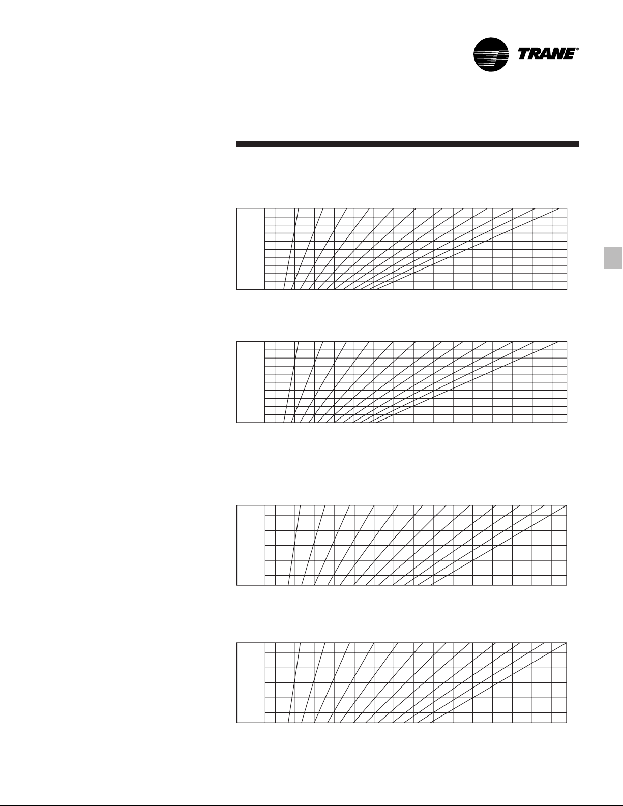
Charts S-2 and S-3 give the total amount
of expansion for various lengths of
copper or steel tube when installed at
40°F (4.4°C) and operated at different hot
water or steam temperatures.
*Based on wall fin installed at 40°F (4.4°C). For wall fin
installed at other temperatures, subtract the installation
temperature from the operating temperature to find the
actual temperature difference. Add this difference to
40°F (4.4°C). Now read in Chart S-2 or S-3 from the
temperature obtained across to installed length and
down to the amount of expansion.
Chart S-2— Expansion in Steel Elements and Steel Pipe
OPERATING
TEMP* 5 10 15 20 2530 3540 45 5055 60
INSTALLED LENGTH (IN FEET) ENGLISH
400°F
350°F
300°F
250°F
200°F
0
OPERATING
TEMP*
204°C
177°C
149°C
121°C
93°C
1
/4
1.5 3.1 4.6 6.1 7.6 9.1 10.7 12.2 13.7 15.2 16.8 18.3
1
/2
AMOUNT OF EXPANSION (IN INCHES)
INSTALLED LENGTH (IN METERS)
3
/4 11
1
/4 1 1/2 1 3/4
SI
0 6 13 19 25 32 38 44
AMOUNT OF EXPANSION (IN MILLIMETERS)
Chart S-3 — Expansion in Copper-Aluminum Elements and Copper Tube
OPERATING
TEMP* 5 1015202530354045505560
300°F
250°F
200°F
0
1
/4
INSTALLED LENGTH (IN FEET) ENGLISH
1
/2
AMOUNT OF EXPANSION (IN INCHES)
3
/4 11
1
/4 1 1/2 1 3/4
OPERATING
TEMP*
149°C
121°C
93°C
1.5 3.1 4.6 6.1 7.6 9.1 10.7 12.2 13.7 15.2 16.8 18.3
INSTALLED LENGTH (IN METERS) SI
0 6 13 19 25 32 38 44
AMOUNT OF EXPANSION (IN MILLIMETERS)
13FIN-PRC004-EN
Page 14

Performance
Data
Bare Element Capacities
Table PD-1 — Ratings of Wall Fin Copper/Aluminum Elements Without Enclosures
Fin Series Height EDR 104°C99°C93°C88°C82°C77°C71°C66°C60°C54°C49°C43°C38°C
Element Per Meter Tiers mm Sq. M Watts/Meter 1.05 0.95 0.86 0.78 0.69 0.61 0.53 0.45 0.40 0.33 0.26 0.20 0.15
3
/4” CA 40 2** 18 8.70 2090 2195 1985 1800 1630 1440 1275 1105 940 835 690 545 420 315
19 mm 131m 457 94 2010 2110 1910 1730 1570 1380 1230 1060 904 803 664 524 404 303
Copper Tube 3** 27
Alum. Fins 699 126 2710 2850 2580 2330 2120 1870 1650 1440 1220 1090 894 707 543 404
Fins 3 1/4 “ x 3 1/4” 1†—3.93 945 990 900 810 735 650 575 500 425 380 310 245 190 140
83 x 83 mm 42 909 952 865 779 707 625 553 481 409 365 298 236 183 135
Thickness .0135” 18 1/2 512 1230 1290 1170 1060 960 850 750 650 555 490 405 320 245 185
.34 mm 216 5510 1180 1240 1120 1020 923 817 721 625 534 471 389 308 236 178
Per Foot Inches Sq. Ft. Btu/Hr./Ft. IBR Factor — Steam to Hot Water
50 2** 18 9.33 2240 2350 2130 1925 1745 1545 1365 1185 1010 895 740 580 450 335
164 m 457 100 2150 2260 2050 1850 1680 1490 1310 1140 971 861 712 558 433 322
58 2** 18 9.66 2320 2435 2205 1995 1810 1600 1415 1230 1045 930 765 605 465 350
190 m 457 104 2230 2340 2120 1920 1740 1540 1360 1180 1000 894 736 582 447 337
Install. 220°F 210°F 200°F 190°F 180°F 170°F 160°F 150°F 140°F 130°F 120°F 110°F 100°F
18 1/2 4.62 1110 1055 1165 955 865 765 680 590 500 445 365 290 220 165
2* 14 8.33 2000 2100 1900 1720 1560 1380 1220 1060 900 800 660 520 400 300
2* 14 8.70 2090 2195 1985 1795 1630 1440 1275 1110 940 835 690 545 420 315
3** 27
1†—4.35 1045 1095 990 900 815 720 635 555 470 420 345 270 210 155
18 1/2 5.41 1300 1365 1235 1120 1015 895 795 690 585 520 430 340 260 195
2* 14 8.87 2130 2235 2025 1830 1660 1470 1300 1130 960 850 705 555 425 320
3** 27
1†—4.60 1105 1160 1050 950 860 760 675 585 500 440 365 285 220 165
Steam Capacity Hot Water Capacity
Per Ft.-1 Psi at 65°F Air Btu/Hr./Ft. — At 65°F Air, Average Water Temperature
Per Meter - 6.895 kPa Watts/Meter — At 18.3°C Air, Average Water Temperature
at 18.3°C Air
216 50 1070 1010 1120 918 832 736 654 567 481 428 351 279 212 159
356 90 1920 2020 1830 1650 1500 1330 1170 1020 865 769 635 500 385 288
1
/2 11.75 2820 2960 2680 2425 2200 1945 1720 1495 1270 1130 930 735 565 420
356 94 2010 2110 1910 1730 1570 1380 1230 1070 904 803 664 524 404 303
1
/2 12.41 2980 3130 2830 2560 2325 2055 1815 1580 1340 1190 975 775 595 445
699 134 2870 3010 2720 2460 2240 1980 1740 1520 1290 1140 947 745 572 428
47 1000 1050 952 865 784 692 611 534 452 404 332 260 202 149
216 58 1250 1310 1190 1080 976 861 764 664 563 500 413 327 250 188
356 95 2050 2150 1950 1760 1600 1410 1250 1090 923 817 678 534 409 308
1
/2 12.75 3060 3215 2905 2630 2385 2110 1865 1620 1375 1225 1010 795 610 460
699 137 2940 3090 2790 2530 2290 2030 1790 1560 1320 1180 971 764 587 442
50 1060 1120 1010 914 827 731 649 563 481 423 351 274 212 159
FIN-PRC004-EN14
Page 15

Performance
Data
Table PD-1 — Ratings of Wall Fin Copper/Aluminum Elements Without Enclosures
Steam Capacity Hot Water Capacity
Per Ft.-1 Psi at 65°F Air Btu/Hr./Ft. — At 65°F Air, Average Water Temperature
Per Meter - 6.895 kPa Watts/Meter — At 18.3°C Air, Average Water Temperature
Fin Series Height EDR 104°C99°C93°C88°C82°C77°C71°C66°C60°C54°C49°C43°C38°C
Element Per Meter Tiers mm Sq. M Watts/Meter 1.05 0.95 0.86 0.78 0.69 0.61 0.53 0.45 0.40 0.33 0.26 0.20 0.15
1” CA 40 2** 18 8.70 2090 2195 1985 1800 1630 1440 1275 1105 940 835 690 545 420 315
25 mm 131m 457 94 2010 2110 1910 1730 1570 1380 1230 1060 904 803 664 524 404 303
Copper Tube 3** 27
Alum. Fins 699 126 2710 2850 2580 2330 2120 1870 1650 1440 1220 1090 894 707 543 404
1
Fins 3
/4” x 3 1/4” 1†—3.93 945 990 900 810 735 650 575 500 425 380 310 245 190 140
83 x 83 mm 42 909 952 865 779 707 625 553 481 409 365 298 236 183 135
Thickness .0135” 18 1/2 5.08 1220 1280 1160 1050 950 840 745 645 550 490 400 315 245 185
.34 mm 216 55 1170 1230 1120 1010 914 808 716 620 529 471 385 303 236 178
*5 1/2” (140 mm) Centers
1
**9
/2” (241 mm) Centers
† At Ceiling
Dimensions in bold indicate metric units.
Per Foot Inches Sq. Ft. Btu/Hr./Ft. IBR Factor — Steam to Hot Water
50 2** 18 9.25 2220 2330 2110 1910 1730 1530 1355 1175 1000 890 730 575 445 330
164 m 457 100 2140 2240 2030 1840 1660 1470 1300 1130 962 856 702 553 428 317
58 2** 18 9.50 2280 2395 2165 1960 1780 1575 1390 1210 1025 910 750 590 455 340
190 m 457 102 2190 2300 2080 1880 1710 1520 1340 1160 986 875 721 567 438 327
Install. 220°F 210°F 200°F 190°F 180°F 170°F 160°F 150°F 140°F 130°F 120°F 110°F 100°F
18 1/2 4.62 1110 1165 1055 955 865 765 680 590 500 445 365 290 220 165
216 50 1070 1120 10101 918 832 736 654 567 481 428 351 279 212 159
2* 14 8.33 2000 2100 1900 1720 1560 1380 1220 1060 900 800 660 520 400 300
356 90 1920 2020 1830 1650 1500 1330 1170 1020 865 769 635 500 385 288
2* 14 8.58 2060 2165 1955 1770 1605 1420 1255 1090 925 825 680 535 410 310
356 92 1980 2080 1880 1700 1540 1360 1210 1050 889 793 654 514 394 298
3** 27
699 132 2840 2980 2690 2440 2210 1960 1730 1500 1270 1140 938 736 567 423
1†—4.33 1040 1090 990 895 810 715 635 550 470 415 340 270 210 155
18 1/2 5.33 1280 1345 1215 1100 1000 885 780 680 575 510 420 330 255 190
216 57 1230 1290 1170 1060 962 851 750 654 553 490 404 317 245 183
2* 14 8.75 2100 2205 1995 1805 1640 1450 1280 1115 945 840 695 545 420 315
356 94 2020 2120 1920 1740 1580 1390 1230 1070 909 808 668 524 404 303
3** 27
699 135 2890 3040 2750 2490 2260 2000 1760 1530 1300 1160 957 750 577 433
1†—4.54 1090 1145 1035 935 850 750 665 575 490 435 360 285 220 160
at 18.3C Air
1
/2 11.75 2820 2960 2680 2425 2200 1945 1720 1495 1270 1130 930 735 565 420
1
/2 12.29 2950 3095 2800 2535 2300 2035 1800 1565 1325 1180 975 765 590 440
47 1000 1050 952 861 779 688 611 529 452 399 327 260 202 149
1
/2 12.54 3010 3160 2860 2590 2350 2075 1835 1595 1355 1205 995 780 600 450
49 1050 1100 995 899 817 721 639 553 471 418 346 274 212 154
15FIN-PRC004-EN
Page 16

Performance
Data
Table PD-2 — Ratings of Wall Fin Copper/Aluminum Elements Without Enclosures
Steam Capacity Hot Water Capacity
Per Ft.-1 Psi at 65°F Air Btu/Hr./Ft. — At 65°F Air, Average Water Temperature
Per Meter - 6.895 kPa Watts/Meter — At 18.3°C Air, Average Water Temperature
Fin Series Height EDR 104°C99°C93°C88°C82°C77°C71°C66°C60°C54°C49°C43°C38°C
Element Per Meter Tiers mm Sq. M Watts/Meter 1.05 0.95 0.86 0.78 0.69 0.61 0.53 0.45 0.40 0.33 0.26 0.20 0.15
1
/4” CA 40 2** 18 8.75 2100 2205 1995 1805 1640 1450 1280 1115 945 840 695 545 420 315
1
32 mm 131 m 457 94 2020 2120 1920 1740 1580 1390 1230 1070 909 808 668 524 404 303
Copper Tube 3** 27
Alum. Fins 699 126 2710 2850 2580 2330 2120 1870 1650 1440 1220 1090 894 707 543 409
1
Fins 3
/4” x 3 1/4” 1†—3.95 950 1000 900 815 740 655 580 505 430 380 315 245 190 140
83 x 83 mm 43 914 962 865 784 712 630 558 486 413 365 303 236 183 135
Thickness .0135” 18 1/2 5.08 1220 1280 1160 1050 950 840 745 650 550 490 400 315 245 185
.34 mm 216 55 1170 1230 1120 1010 914 808 716 625 529 471 385 303 236 178
Per Foot Inches Sq. Ft. Btu/Hr./Ft. IBR Factor — Steam to Hot Water
50 2** 18 9.16 2200 2310 2090 1890 1715 1520 1340 1165 990 880 725 570 440 330
164 m 457 99 2120 2220 2010 1820 1650 1460 1290 1120 952 846 697 548 423 317
58 2* 14 8.58 2060 2165 1955 1770 1605 1420 1255 1090 925 825 680 535 410 310
190 m 356 92 1980 2080 1880 1700 1540 1360 1210 1050 889 793 654 514 394 298
Install. 220°F 210°F 200°F 190°F 180°F 170°F 160°F 150°F 140°F 130°F 120°F 110°F 100°F
18 1/2 4.66 1120 1175 1065 965 875 770 685 595 505 450 370 290 225 170
216 50 1080 1130 1020 928 841 740 659 572 486 433 356 279 216 163
2* 14 8.37 2010 2110 1910 1730 1565 1385 1225 1065 905 805 665 520 440 300
356 90 1930 2030 1840 1660 1500 1330 1180 1020 870 774 639 500 385 288
2* 14 8.50 2040 2140 1940 1755 1590 1405 1245 1080 920 815 675 530 410 305
356 91 1960 2060 1870 1690 1530 1350 1200 1040 885 784 649 510 394 293
3** 27
699 130 2800 2940 2660 2400 2180 1930 1710 1480 1260 1120 923 726 558 418
1†—4.33 1040 1090 990 895 810 720 635 550 470 415 345 270 210 155
18 1/2 5.29 1270 1335 1205 1090 990 875 775 675 570 510 420 330 255 190
216 57 1220 1280 1160 1050 952 841 745 649 548 490 404 317 245 183
2** 18 9.37 2250 2360 2140 1935 1755 1550 1370 1190 1010 900 740 585 450 335
457 101 2160 2270 2060 1860 1690 1490 1320 1140 971 865 712 563 433 322
3** 27
699 133 2850 2990 2700 2450 2220 1960 1740 1510 1280 1140 938 740 567 428
1†—4.50 1080 1135 1025 930 840 745 660 570 485 430 355 280 215 160
at 18.3C Air
1
/2 11.75 2820 2960 2680 2425 2200 1945 1720 1495 1270 1130 930 735 565 425
1
/2 12.12 2910 3055 2765 2500 2270 2010 1775 1540 1310 1165 960 755 580 435
47 1000 1050 950 860 780 690 610 530 450 400 330 260 200 150
1
/2 12.33 2960 3105 2810 2545 2310 2040 1805 1570 1330 1185 975 770 590 445
48 1040 1090 986 894 808 716 635 548 466 413 341 269 207 154
FIN-PRC004-EN16
Page 17

Performance
Data
Table PD-2 — Ratings of Wall Fin Copper/Aluminum Elements Without Enclosures
Steam Capacity Hot Water Capacity
Per Ft.-1 Psi at 65°F Air Btu/Hr./Ft. — At 65°F Air, Average Water Temperature
Per Meter - 6.895 kPa Watts/Meter — At 18.3°C Air, Average Water Temperature
Fin Series Height EDR 104°C99°C93°C88°C82°C77°C71°C66°C60°C54°C49°C43°C38°C
Element Per Meter Tiers mm Sq. M Watts/Meter 1.05 0.95 0.86 0.78 0.69 0.61 0.53 0.45 0.40 0.33 0.26 0.20 0.15
1
/4” CA 40 2** 18 12.16 2920 3065 2775 2510 2275 2015 1780 1545 1315 1170 965 760 585 440
1
32 mm 131 m 457 131 2810 2950 2670 2410 2190 1940 1710 1490 1260 1120 928 731 563 423
Copper Tube 3** 27
Alum. Fins 699 177 3790 3980 3600 3260 2960 2620 2310 2010 1710 1520 1250 986 760 567
1
Fins 3
/4” x 5 1/4” 1†—5.52 1325 1390 1260 1140 1035 915 810 700 595 530 435 345 265 200
83 x 133 mm 59 1270 1340 1210 1100 995 880 779 673 572 510 418 332 255 192
Thickness .0135” 18 1/2 7.33 1760 1850 1670 1515 1370 1215 1075 930 790 705 580 460 350 265
.34 mm 216 79 1690 1780 1610 1460 1320 1170 1030 894 760 678 558 442 337 255
*5 1/2” (140 mm) Centers
1
**9
/2” (241 mm) Centers
† At Ceiling
Dimensions in bold indicate metric units.
Per Foot Inches Sq. Ft. Btu/Hr./Ft. IBR Factor — Steam to Hot Water
50 2** 18 12.87 3090 3245 2935 2655 2410 2130 1885 1635 1390 1235 1020 805 620 465
164 m 457 139 2970 3120 2820 2550 2320 2050 1810 1570 1340 1190 981 774 596 447
58 2** 18 13.20 3170 3330 3010 2725 2470 2185 1935 1680 1425 1270 1045 825 635 475
190 m 457 142 3050 3200 2890 2620 2380 2100 1860 1620 1370 1220 1000 793 611 457
Install. 220°F 210°F 200°F 190°F 180°F 170°F 160°F 150°F 140°F 130°F 120°F 110°F 100°F
18 1/2 6.50 1560 1640 1480 1340 1215 1075 950 825 700 625 515 405 310 235
216 70 1500 1580 1420 1290 1170 1030 914 793 673 601 495 389 298 226
2* 14 11.66 2800 2940 2660 2410 2185 1930 1710 1485 1260 1120 925 730 560 420
356 126 2690 2830 2560 2320 2100 1860 1640 1430 1210 1080 889 702 538 404
2* 14 12.08 2900 3045 2755 2495 2260 2000 1770 1535 1305 1160 955 755 580 435
356 130 2790 2930 2650 2400 2170 1920 1700 1480 1260 1120 918 726 558 418
3** 27
699 182 3890 4090 3700 3350 3040 2690 2380 2060 1750 1560 1280 1010 779 587
1†—6.23 1495 1570 1420 1285 1165 1030 910 790 670 600 495 390 300 225
18 1/4 7.75 1860 1955 1765 1600 1450 1285 1135 985 835 745 615 485 370 280
210 83 1790 1880 1700 1540 1390 1240 1090 947 803 716 591 466 356 269
2* 14 12.33 2960 3110 2810 2545 2310 2040 1805 1570 1330 1185 975 770 590 445
356 133 2850 2990 2700 2450 2220 1960 1740 1510 1280 1140 938 740 567 428
3** 27
699 184 3950 4150 3760 3400 3080 2730 2410 2100 1780 1580 1300 1030 789 591
1†—6.58 1580 1660 1500 1360 1230 1090 965 840 710 630 520 410 315 240
at 18.3C Air
1
/2 16.41 3940 4135 3745 3390 3075 2720 2405 2090 1775 1575 1300 1025 790 590
1
/2 16.87 4050 4250 3850 3485 3160 2795 2470 2145 1820 1620 1335 1055 810 610
67 1440 1510 1360 1240 1120 990 875 760 644 577 476 375 288 216
1
/2 17.12 4110 4315 3905 3535 3205 2835 2505 2180 1850 1645 1355 1070 820 615
71 1520 1600 1440 1310 1180 1050 928 808 683 606 500 394 303 231
17FIN-PRC004-EN
Page 18

Performance
Data
Table PD-3 — Ratings of Wall Fin Steel Elements Without Enclosures
Steam Capacity Hot Water Capacity
Per Ft.-1 Psi at 65°F Air Btu/Hr./Ft. — At 65°F Air, Average Water Temperature
Per Meter - 6.895 kPa Watts/Meter — At 18.3°C Air, Average Water Temperature
Fin Series Height EDR 104°C99°C93°C88°C82°C77°C71°C66°C60°C54°C49°C43°C38°C
Element Per Meter Tiers mm Sq. M Watts/Meter 1.05 0.95 0.86 0.78 0.69 0.61 0.53 0.45 0.40 0.33 0.26 0.20 0.15
1
1
/4” Steel 229 64 1380 1440 1310 1180 1080 952 837 731 615 548 452 356 274 207
32 mm 2* 13 8.60 2060 2160 1960 1770 1610 1420 1260 1090 925 825 680 535 410 310
Steel Tube 330 93 1980 2080 1880 1700 1550 1360 1210 1050 889 793 654 514 394 298
Steel Fins 52 2** 17 9.90 2370 2490 2250 2040 1850 1640 1450 1255 1065 945 780 615 475 355
1
/2” x 5 1/4” 171m 432 107 2280 2390 2160 1960 1780 1580 1390 1210 1020 909 750 591 457 341
Fins 2
64 x 133 mm 3** 23 13.25 3180 3340 3020 2730 2480 2190 1940 1685 1430 1270 1050 825 635 475
Thickness .027” 584 143 3060 3210 2900 2620 2380 2110 1870 1620 1380 1220 1010 793 611 457
.69 mm 1†—5.00 1200 1260 1140 1030 940 830 730 635 540 480 395 310 240 180
*4” (102 mm) Centers
** 8” (203 mm) Centers
† At Ceiling
Dimensions in bold indicate metric units.
Per Foot Inches Sq. Ft. Btu/Hr./Ft. IBR Factor — Steam to Hot Water
Install. 220°F 210°F 200°F 190°F 180°F 170°F 160°F 150°F 140°F 130°F 120°F 110°F 100°F
1 9 5.95 1430 1500 1360 1230 1120 990 870 760 640 570 470 370 285 215
at 18.3°C Air
54 1150 1210 1100 990 904 798 702 611 519 462 380 298 231 173
Metric Conversions
1 Psi = 6.895 kPa (Kilo Pascals) at 65°F Air = 18.3°C Air
Sq. Ft. EDR at 1 Psi (6.895 kPa) at 65°F Air (18.3°C) Air x 240 BTU = Total BTU’s (Watts)
1 BTU/HR. = 0.2931 Watts
1 Foot = 0.3048 Meters - 1 Meter = 3.2808 Feet
1 BTU/HR/FT = 0.9616 Watts/Meter
10.7639 Sq. Feet = 1 Square Meter
1 Lbs = 0.4536 Kg (Kilograms)
1 Inch = 25.4 mm (Millimeters)
Note:
All shown capacities based on finned length at a water velocity of three feet per second or 0.9144 meter per second or greater.
FIN-PRC004-EN18
Page 19

Performance
Sloping
Data
Top
Table PD-4 — Ratings 4” (102 mm) Deep, Type S - Enclosure With Copper/Aluminum Elements
Steam Capacity Hot Water Capacity
Per Ft.-1 Psi at 65°F Air Btu/Hr./Ft. — At 65°F Air, Average Water Temperature
Per Meter - 6.895 kPa Watts/Meter — At 18.3°C Air, Average Water Temperature
Fin Series Height EDR 104°C99°C93°C88°C82°C77°C71°C66°C60°C54°C49°C43°C38°C
Element Per Meter Tiers Encl. mm Sq. M Watts/Meter 1.05 0.95 0.86 0.78 0.69 0.61 0.53 0.45 0.40 0.33 0.26 0.20 0.15
3
/4” CA 40 2* 14S 16 1/8 7.04 1690 1775 1605 1455 1320 1165 1030 895 760 675 555 440 340 255
19 mm 131 m 410 76 1620 1710 1540 1400 1270 1120 990 861 731 649 534 423 327 245
Copper Tube 18S 20 1/8 7.62 1830 1920 1740 1575 1425 1260 1115 970 825 730 605 475 365 275
Alum. Fins 511 82 1760 1850 1670 1520 1370 1210 1070 933 793 702 582 457 351 264
1
Fins 3
/4” x 3 1/4” 2** 24S 26 1/8 8.04 1930 2025 1835 1660 1505 1330 1175 1025 870 770 635 500 385 290
83 x 83 mm 664 87 1860 1950 1760 1600 1450 1280 1130 986 837 740 611 481 370 279
Thickness .0135” 10S 12 1/8 5.16 1240 1300 1180 1065 965 855 755 655 560 495 410 320 250 185
.34 mm 308 56 1190 1250 1140 1020 928 822 726 630 538 476 394 308 240 178
*5 1/2” (140 mm) Centers
1
**9
/2” (241 mm) Centers
24” (610 mm) High ratings not IBR approved.
Dimensions in bold indicate metric units.
Per Foot Inches Sq. Ft. Btu/Hr./Ft. IBR Factor — Steam to Hot Water
1 18S 20 1/8 4.70 1130 1185 1075` 970 880 780 690 600 510 450 370 295 225 170
1 18S 20
50 2* 14S 16 1/8 7.33 1760 1850 1670 1515 1370 1215 1075 930 790 705 580 460 350 265
164 m 410 79 1690 1780 1610 1460 1320 1170 1030 894 760 678 558 442 337 255
2** 24S 26
1 18S 20 1/8 6.58 1580 1660 1500 1360 1230 1090 965 835 710 630 520 410 315 235
58 2* 14S 16 1/8 7.45 1790 1880 1700 1540 1395 1235 1090 950 805 715 590 465 360 270
190 m 410 80 1720 1810 1640 1480 1340 1190 1050 914 774 688 567 447 346 260
2** 24S 26 1/8 9.58 2300 2415 2185 1980 1795 1585 1405 1220 1035 920 760 600 460 345
Install. 220°F 210°F 200°F 190°F 180°F 170°F 160°F 150°F140°F130°F 120°F 110°F 100°F
10S 12 1/8 4.45 10.70 1125 1015 920 835 740 650 565 480 430 355 280 215 160
308 48 1030 1080 976 885 803 712 625 543 462 413 341 269 207 154
14S 16 1/8 4.62 1110 1165 1055 955 865 765 675 590 500 445 365 290 220 165
410 50 1070 1120 1010 918 832 736 649 567 481 428 351 279 212 159
511 51 1090 1140 1030 933 846 750 664 577 490 433 356 284 216 163
24S 26
664 52 1120 1180 1070 966 875 774 688 596 505 452 370 293 226 168
14S 16
410 60 1290 1350 1230 1110 1000 889 784 683 582 514 423 337 260 192
511 64 1380 1440 1310 1180 1070 947 837 731 620 548 452 356 274 207
24S 26
664 68 1450 1520 1380 1250 1140 1000 885 769 654 582 481 375 288 216
18S 20 1/8 8.33 2000 2100 1900 1720 1560 1380 1220 1060 900 800 660 520 400 300
511 90 1920 2020 1830 1650 1500 1330 1170 1020 865 769 635 500 385 288
664 96 2070 2170 1960 1780 1610 1430 1260 1100 928 827 683 538 413 308
10S 12 1/8 5.54 1330 1395 1265 1145 1035 920 810 705 600 530 440 345 265 200
308 60 1280 1340 1220 1100 995 885 779 678 577 510 423 332 255 192
14S 16
410 65 1400 1480 1330 1210 1100 966 856 702 630 563 462 365 279 212
511 71 1520 1600 1440 1310 1180 1050 928 803 683 606 500 394 303 226
24S 26
664 76 1640 1720 1550 1400 1270 1130 995 865 736 654 538 423 327 245
18S 20 1/8 8.70 2090 2195 1985 1795 1630 1440 1275 1105 904 835 690 545 420 315
511 94 2010 2110 1910 1730 1570 1380 1230 1060 869 803 664 524 404 303
664 103 2210 2320 2100 1900 1730 1520 1350 1170 995 885 731 577 442 332
at 18.3°C Air
1
/8 4.87 1170 1230 1110 1005 910 805 715 620 525 470 385 305 235 175
1
/8 5.58 1340 1405 1275 1150 1045 925 815 710 605 535 440 350 270 200
1
/8 5.95 1430 1500 1360 1230 1115 985 870 760 645 570 470 370 285 215
1
/8 6.29 1510 1585 1435 1300 1180 1040 920 800 680 605 500 390 300 225
1
/8 8.95 2150 2260 2040 1850 1675 1485 1310 1140 965 860 710 560 430 320
1
/8 6.08 1460 1535 1385 1255 1140 1005 890 730 655 585 480 380 290 220
1
/8 7.08 1700 1785 1615 1460 1325 1175 1035 900 765 680 560 440 340 255
NOTE: Rating is Btu/hr/ft (Watts/meter) of finned length (for element dimensions see page 49). Hot water ratings determined by applying correction factor to steam ratings, are for
water velocities of 3 ft/sec (.91 m/s) or greater. See page 9, Chart S-1 for correction factors for water velocities other than 3 ft/sec (.91 m/s). For definition of installed height and heating
effect factors, see page 11. For heating ratings at other steam pressures and/or entering air temperatures, see page 10, Table S-2.
19FIN-PRC004-EN
Page 20

Performance
Sloping
Data
Top
Table PD-5 — Ratings 4” (102 mm) Deep, Type S - Enclosure With Copper/Aluminum Elements
Steam Capacity Hot Water Capacity
Per Ft.-1 Psi at 65°F Air Btu/Hr./Ft. — At 65°F Air, Average Water Temperature
Per Meter - 6.895 kPa Watts/Meter — At 18.3°C Air, Average Water Temperature
Fin Series Height EDR 104°C99°C93°C88°C82°C77°C71°C66°C60°C54°C49°C43°C38°C
Element Per Meter Tiers Encl. mm Sq. M Watts/Meter 1.05 0.95 0.86 0.78 0.69 0.61 0.53 0.45 0.40 0.33 0.26 0.20 0.15
1” CA 40 2* 14S 16 1/8 7.04 1690 1775 1605 1455 1320 1165 1030 895 760 675 560 440 340 255
25 mm 131 m 410 76 1620 1710 1540 1400 1270 1120 990 861 731 649 538 423 327 245
Copper Tube 18S 20 1/8 7.62 1830 1920 1740 1575 1425 1260 1115 970 825 730 605 475 365 275
Alum. Fins 511 82 1760 1850 1670 1520 1370 1210 1070 933 793 702 582 457 351 264
1
Fins 3
/4” x 3 1/4” 2** 24S 26 1/8 8.04 1930 2025 1835 1660 1505 1330 1175 1020 870 770 635 500 385 290
83 x 83 mm 664 87 1860 1950 1760 1600 1450 1280 1130 981 837 740 611 481 370 279
Thickness .0135” 10S 12 1/8 5.16 1240 1300 1180 1065 965 855 755 655 560 495 410 320 250 185
.34 mm 308 56 1190 1250 1140 1020 928 822 726 630 538 476 394 308 240 178
*5 1/2” (140 mm) Centers
1
**9
/2” (241 mm) Centers
24” (610 mm) High ratings not IBR approved.
Dimensions in bold indicate metric units.
Per Foot Inches Sq. Ft. Btu/Hr./Ft. IBR Factor — Steam to Hot Water
1 18S 20
1 18S 20
50 2* 14S 16 1/8 7.16 1720 1805 1635 1480 1340 1185 1050 910 775 690 570 445 345 260
164 m 410 77 1650 1740 1570 1420 1290 1140 1010 875 745 664 548 428 332 250
2** 24S 26
1 18S 20
58 2* 14S 16 1/8 7.21 1730 1815 1645 1490 1350 1195 1055 915 780 690 570 450 345 260
190 m 410 78 1660 1740 1580 1430 1300 1150 1010 880 750 664 548 433 332 250
2** 24S 26
Install. 220°F 210°F 200°F 190°F 180°F 170°F 160°F 150°F140°F130°F 120°F 110°F 100°F
10S 12 1/8 4.50 1080 1135 1025 930 842 745 660 570 485 430 355 280 215 160
308 48 1040 1090 986 894 810 716 635 548 466 413 341 269 207 154
14S 16
24S 26
14S 16 1/8 5.62 1350 1420 1280 1160 1055 930 825 715 610 540 445 350 270 200
24S 26 1/8 6.33 1520 1595 1445 1305 1185 1050 925 805 685 610 500 395 305 230
18S 20 1/8 8.16 1960 2060 1860 1685 1530 1350 1195 1040 880 785 645 510 390 295
10S 12 1/8 5.50 1320 1385 1255 1135 1030 910 805 700 595 530 435 345 265 200
14S 16
24S 26
18S 20 1/8 8.45 2030 2130 1930 1745 1585 1400 1240 1075 915 810 670 530 405 305
1
410 50 1080 1130 1020 928 841 740 659 572 486 433 356 279 216 163
1
511 52 1110 1160 1050 952 861 764 673 587 500 442 365 288 221 168
1
664 53 1140 1200 1090 986 894 789 697 606 514 457 375 298 231 173
410 60 1300 1360 1230 1120 1010 894 793 688 587 519 428 337 260 192
1
511 65 1380 1450 1320 1190 1080 957 846 736 625 553 457 361 279 207
664 68 1460 1530 1390 1260 1140 1010 889 774 659 587 481 380 293 221
511 88 1880 1980 1790 1620 1470 1300 1150 1000 846 755 620 490 375 284
1
664 94 2020 2120 1920 1740 1580 1390 1240 1070 909 808 668 524 404 303
308 59 1270 1330 1210 1090 990 875 774 673 572 510 418 332 255 192
1
410 66 1410 1490 1340 1220 1100 976 861 750 635 567 466 365 284 212
1
511 72 1540 1620 1460 1320 1200 1060 938 817 692 615 510 399 308 231
1
664 77 1650 1740 1570 1420 1290 1140 1010 875 745 664 543 428 332 250
511 91 1950 2050 1860 1680 1520 1350 1190 1030 880 779 644 510 389 293
1
664 100 2150 2260 2040 1850 1680 1480 1310 1140 966 861 712 558 428 322
at 18.3°C Air
/8 4.66 1120 1175 1065 965 875 770 685 595 505 450 370 290 225 170
/8 4.79 1150 1210 1090 990 895 795 700 610 520 460 380 300 230 175
/8 4.96 1190 1250 1130 1025 930 820 725 630 535 475 390 310 240 180
/8 6.00 1440 1510 1370 1240 1125 995 880 765 650 575 475 375 290 215
/8 8.77 2105 2210 2000 1810 1640 1450 1285 1115 945 840 695 545 420 315
/8 6.12 1470 1545 1395 1265 1145 1015 895 780 660 590 485 380 295 220
/8 6.66 1600 1680 1520 1375 1250 1105 975 850 720 640 530 415 320 240
/8 7.16 1720 1805 1635 1480 1340 1185 1050 910 775 690 565 445 345 260
/8 9.31 2235 2345 2125 1920 1745 1540 1365 1185 1005 895 740 580 445 335
FIN-PRC004-EN20
Page 21

Performance
Sloping
Data
Top
Table PD-6 — Ratings 4” (102 mm) Deep, Type S - Enclosure With Copper/Aluminum Elements
Steam Capacity Hot Water Capacity
Per Ft.-1 Psi at 65°F Air Btu/Hr./Ft. — At 65°F Air, Average Water Temperature
Per Meter - 6.895 kPa Watts/Meter — At 18.3°C Air, Average Water Temperature
Fin Series Height EDR 104°C99°C93°C88°C82°C77°C71°C66°C60°C54°C49°C43°C38°C
Element Per Meter Tiers Encl. mm Sq. M Watts/Meter 1.05 0.95 0.86 0.78 0.69 0.61 0.53 0.45 0.40 0.33 0.26 0.20 0.15
1 1/4” CA 40 2* 14S 16 1/8 7.04 1690 1775 1605 1455 1320 1165 970 895 760 675 560 430 340 255
32 mm 131 m 410 76 1620 1710 1540 1400 1270 1120 990 861 731 649 538 413 327 245
Copper Tube 18S 20 1/8 7.58 1820 1910 1730 1565 1420 1255 1110 965 820 730 600 475 365 275
Alum. Fins 511 82 1750 1840 1660 1500 1360 1210 1070 928 789 702 577 457 351 264
Fins 3 1/4” x 3 1/4” 2** 24S 26 1/8 8.00 1920 2015 1825 1650 1500 1325 1170 1020 865 770 635 500 385 290
83 x 83 mm 664 86 1850 1940 1760 1590 1440 1270 1120 981 832 740 611 481 370 279
Thickness .0135” 10S 12 1/8 5.12 1230 1290 1170 1060 960 850 750 650 555 490 405 320 245 185
.34 mm 308 55 1180 1240 1120 1020 923 817 721 625 534 471 389 308 236 178
*5 1/2” (140 mm) Centers
1
**9
/2” (241 mm) Centers
24” (610 mm) High ratings not IBR approved.
Dimensions in bold indicate metric units.
Per Foot Inches Sq. Ft. Btu/Hr./Ft. IBR Factor — Steam to Hot Water
1 18S 20
1 18S 20
50 2* 14S 16 1/8 7.00 1680 1765 1595 1445 1310 1160 990 890 755 670 555 435 335 250
164 m 410 75 1620 1700 1530 1390 1260 1120 986 857 726 644 534 418 322 240
2** 24S 26
1 18S 20
58 2* 14S 16 1/8 7.00 1680 1765 1595 1445 1310 1160 995 890 755 670 555 435 335 250
190 mm 410 75 1620 1700 1530 1390 1260 1120 986 856 726 644 534 418 322 240
2** 24S 26
Install. 220°F 210°F 200°F 190°F 180°F 170°F 160°F 150°F140°F130°F 120°F 110°F 100°F
10S 12 1/8 4.54 1090 1145 1035 935 850 750 665 580 490 435 360 285 220 160
308 49 1050 1100 995 899 817 721 639 558 471 418 346 274 212 154
14S 16 1/8 4.75 1140 1195 1085 980 890 785 695 605 515 455 375 295 230 170
410 51 1100 1150 1040 942 856 755 668 582 495 438 361 284 221 163
511 52 1120 1180 1070 966 875 774 688 596 505 452 370 293 226 168
24S 26
664 54 1160 1220 1110 1000 909 803 712 615 524 466 385 303 231 173
14S 16
410 61 1310 1380 1240 1120 1020 904 798 692 587 524 433 341 260 197
511 65 1400 1480 1330 1210 1100 966 856 745 630 563 462 365 279 212
24S 26
664 69 1480 1550 1410 1270 1150 1020 904 784 668 591 490 385 298 221
18S 20 1/8 8.00 1920 2015 1825 1650 1500 1325 1170 1020 865 770 635 500 385 290
511 86 1850 1940 1760 1590 1440 1270 1120 981 832 740 611 481 370 279
664 93 1990 2090 1880 1710 1550 1370 1210 1050 894 793 654 514 399 298
10S 12 1/8 5.45 1310 1375 1245 1125 1020 905 800 695 590 525 430 340 260 195
308 59 1260 1320 1200 1080 981 870 769 668 567 505 413 327 250 188
14S 16
410 66 1410 1490 1340 1220 1100 976 861 750 635 567 466 365 284 212
511 73 1560 1640 1480 1340 1220 1080 952 827 702 625 514 404 313 231
24S 26
664 78 1670 1760 1590 1440 1300 1150 1020 885 750 668 553 433 337 250
18S 20 1/8 8.16 1960 2060 1860 1685 1530 1350 1195 1040 880 785 645 510 390 295
511 88 1880 1980 1790 1620 1470 1300 1150 1000 846 755 620 490 375 284
664 97 2070 2170 1970 1780 1620 1430 1260 1100 933 827 683 538 413 313
at 18.3°C Air
1
/8 4.87 1170 1230 1110 1005 910 805 715 620 525 470 385 305 235 175
1
/8 5.04 1210 1270 1150 1040 945 835 740 640 545 485 400 315 240 180
1
/8 5.66 1360 1430 1290 1170 1060 940 830 720 610 545 450 355 270 205
1
/8 6.08 1460 1535 1385 1255 1140 1005 890 775 655 585 480 380 290 220
1
/8 6.41 1540 1615 1465 1325 1200 1060 940 815 695 615 510 400 310 230
1
/8 8.60 2065 2170 1960 1775 1610 1425 1260 1095 930 825 680 535 415 310
1
/8 6.12 1470 1545 1395 1265 1145 1015 895 780 660 590 485 380 295 220
1
/8 6.75 1620 1700 1540 1395 1265 1120 990 860 730 650 535 420 325 240
1
/8 7.25 1740 1825 1655 1495 1355 1200 1060 920 780 695 575 450 350 260
1
/8 8.98 2155 2260 2045 1855 1680 1485 1315 1140 970 860 710 560 430 325
21FIN-PRC004-EN
Page 22

Performance
Sloping
Data
Top
Table PD-7 — Ratings 6” (152 mm) Deep, Type S - Enclosure With Copper/Aluminum Elements
Steam Capacity Hot Water Capacity
Per Ft.-1 Psi at 65°F Air Btu/Hr./Ft. — At 65°F Air, Average Water Temperature
Per Meter - 6.895 kPa Watts/Meter — At 18.3°C Air, Average Water Temperature
Fin Series Height EDR 104°C99°C93°C88°C82°C77°C71°C66°C60°C54°C49°C43°C38°C
Element Per Meter Tiers Encl. mm Sq. M Watts/Meter 1.05 0.95 0.86 0.78 0.69 0.61 0.53 0.45 0.40 0.33 0.26 0.20 0.15
1 1/4” CA 40 2* 16S 17 1/4 10.70 2570 2695 2440 2210 2005 1775 1570 1360 1155 1030 850 670 515 385
32 mm 131 m 438 115 2470 2590 2350 2120 1930 1710 1510 1310 1110 990 817 644 495 370
Copper Tube 20S 21 1/4 11.25 2700 2835 2565 2320 2105 1865 1645 1430 1215 1080 890 700 540 405
Alum. Fins 540 121 2600 2730 2470 2230 2020 1790 1580 1380 1170 1040 856 673 519 389
1
Fins 3
/4” x 5 1/4” 2** 24S 25 1/4 11.87 2850 2990 2710 2450 2220 1965 1740 1510 1280 1140 940 740 570 425
83 x 133 mm 641 128 2740 2880 2610 2360 2140 1890 1670 1450 1230 1100 904 712 548 409
Thickness .0135” 12S 13 1/4 7.83 1880 1975 1785 1615 1465 1300 1145 995 845 750 620 490 375 280
.34 mm 337 84 1810 1900 1720 1550 1410 1250 1100 957 813 721 596 471 361 269
*5 1/2” (140 mm) Centers
1
**9
/2” (241 mm) Centers
24S High ratings not IBR approved.
Dimensions in bold indicate metric units.
Per Foot Inches Sq. Ft. Btu/Hr./Ft. IBR Factor — Steam to Hot Water
1 20S 21
1 20S 21
50 2* 16S 17 1/4 11.08 2660 2795 2525 2290 2075 1835 1620 1410 1195 1065 880 690 530 400
164 m 438 119 2560 2690 2430 2200 2000 1760 1560 1360 1150 1020 846 664 510 385
2** 24S 25
1 20S 21 1/4 10.12 2430 2550 2310 2090 1895 1675 1480 1285 1095 970 800 630 485 365
58 2* 16S 17 1/4 11.29 2710 2845 2575 2330 2115 1870 1655 1435 1220 1085 895 705 540 405
190 m 438 122 2610 2740 2480 2240 2030 1800 1590 1380 1170 1040 861 678 519 389
2** 24S 25 1/4 14.20 3410 3580 3240 2930 2660 2350 2080 1805 1535 1365 1125 885 680 510
Install. 220°F 210°F 200°F 190°F 180°F 170°F 160°F 150°F140°F130°F 120°F 110°F 100°F
12S 13 1/4 6.58 1580 1660 1500 11360 1230 1090 965 835 710 630 520 410 315 235
337 71 1520 1600 1440 1310 1180 1050 928 803 683 606 500 394 303 226
16S 17
24S 25
16S 17
24S 25
20S 21 1/4 12.33 2960 3110 2810 2545 2310 2040 1805 1570 1330 1185 975 770 590 445
12S 13 1/4 8.50 2040 2140 1940 1755 1590 1410 1245 1080 920 815 675 530 410 305
16S 17
24S 25
20S 21 1/4 12.91 3100 3255 2945 2665 2420 2140 1890 1645 1395 1240 1025 805 620 465
1
438 73 1570 1640 1490 1350 1220 1080 957 832 707 625 514 409 313 236
1
540 74 1600 1680 1520 1380 1240 1100 971 846 716 639 529 413 317 240
1
641 77 1650 1740 1570 1420 1290 1140 1010 875 745 664 548 428 332 250
1
438 91 1960 2060 1870 1690 1530 1360 1200 1040 885 784 649 510 394 293
1
540 97 2090 2190 1980 1790 1620 1440 1270 1110 938 837 688 543 418 313
1
641 103 2200 2310 2090 1890 1720 1520 1340 1170 990 880 726 572 442 332
540 133 2850 2990 2700 2450 2220 1960 1740 1510 1280 1140 938 740 567 428
1
641 143 3060 3210 2900 2630 2380 2110 1870 1620 1380 1220 1010 793 611 457
337 91 1960 2060 1870 1690 1530 1360 1200 1040 885 784 649 510 394 293
1
438 101 2170 2280 2060 1870 1700 1500 1330 1150 976 870 716 567 433 327
540 109 2340 2450 2220 2010 1820 1610 1420 1240 1050 933 769 606 466 351
1
641 117 2510 2640 2380 2160 1960 1730 1530 1330 1130 1000 827 654 500 375
540 139 2980 3130 2830 2560 2330 2060 1820 1580 1340 1190 986 774 596 447
641 153 3280 3440 3120 2820 2560 2260 2000 1740 1480 1310 1080 851 654 490
at 18.3°C Air
/4 6.79 1630 1710 1550 1400 1270 1125 995 865 735 650 535 425 325 245
/4 6.91 1660 1745 1575 1430 1295 1145 1010 880 745 665 550 430 330 250
/4 7.16 1720 1805 1635 1480 1340 1185 1050 910 775 690 570 445 345 260
/4 8.50 2040 2140 1940 1755 1590 1410 1245 1080 920 815 675 530 410 305
/4 9.04 2170 2280 2060 1865 1690 1495 1325 1150 975 870 715 565 435 325
/4 9.54 2290 2405 2175 1970 1785 1580 1395 1215 1030 915 755 595 460 345
/4 13.25 3180 3340 3020 2735 2480 2195 1940 1685 1430 1270 1050 825 635 475
/4 9.41 2260 2375 2145 1945 1765 1560 1380 1200 1015 905 745 590 450 340
/4 10.87 2610 2740 2480 2245 2035 1800 1590 1385 1175 1045 860 680 520 390
FIN-PRC004-EN22
Page 23

Performance
Sloping
Data
Top
Table PD-8 — Ratings 6” (152 mm) Deep, Type S - Enclosure With Steel Elements
Steam Capacity Hot Water Capacity
Per Ft.-1 Psi at 65°F Air Btu/Hr./Ft. — At 65°F Air, Average Water Temperature
Per Meter - 6.895 kPa Watts/Meter — At 18.3°C Air, Average Water Temperature
Fin Series Height EDR 104°C99°C93°C88°C82°C77°C71°C66°C60°C54°C49°C43°C38°C
Element Per Meter Tiers Encl. mm Sq. M Watts/Meter 1.05 0.95 0.86 0.78 0.69 0.61 0.53 0.45 0.40 0.33 0.26 0.20 0.15
1
/4” Steel 1 20S 21 7/32 7.25 1740 1830 1650 1500 1360 1200 1060 920 780 695 575 450 345 260
1
32 mm 539 78 1670 1760 1590 1440 1310 1150 1020 885 750 668 553 433 332 250
Steel Tube 24S 25
Steel Fins 640 82 1760 1850 1670 1520 1380 1220 1070 933 793 702 582 457 351 264
Fins 2 1/2” x 5 1/4” 52 16S 17 7/32 9.15 2200 2310 2090 1890 1720 1520 1340 1165 990 880 725 570 440 330
64 x 133 mm 171 m 437 98 2120 2220 2010 1820 1650 1460 1290 1120 952 846 697 548 423 317
Thickness .027” 2* 20S 21 7/32 9.90 2380 2500 2260 2050 1860 1640 1450 1260 1070 950 785 620 475 355
.69 mm 539 107 2290 2400 2170 1970 1790 1580 1390 1210 1030 914 755 596 457 341
*4” (102 mm) Centers
**8” (203 mm) Centers
24S High ratings not IBR approved.
Dimensions in bold indicate metric units.
Per Foot Inches Sq. Ft. Btu/Hr./Ft. IBR Factor — Steam to Hot Water
2** 24S 25
Install. 220°F 210°F 200°F 190°F 180°F 170°F 160°F 150°F140°F 130°F 120°F 110°F 100°F
12S 13 7/32 6.40 1530 1610 1450 1320 1190 1060 930 810 685 610 505 395 305 230
336 69 1470 1550 1390 1270 1140 1020 894 779 659 587 486 380 293 221
16S 17
24S 25
20S 21 7/32 10.25 2460 2580 2340 2120 1920 1700 1500 1305 1105 985 810 640 490 365
7
437 74 1590 1660 1510 1360 1240 1100 971 841 712 635 524 413 317 236
7
7
640 112 2400 2520 2280 2070 1880 1660 1470 1270 1080 962 793 625 481 361
539 110 2370 2480 2250 2040 1850 1640 1400 1260 1060 947 779 615 471 351
7
640 116 2490 2620 2370 2140 1940 1720 1520 1320 1120 995 822 649 500 375
at 18.3°C Air
/32 6.90 1650 1730 1570 1420 1290 1140 1010 875 740 660 545 430 330 245
/32 7.62 1830 1920 1740 1575 1430 1265 1115 970 825 730 605 475 365 275
/32 10.41 2500 2625 2375 2150 1950 1725 1525 1325 1125 1000 825 650 500 375
/32 10.78 2590 2720 2460 2225 2020 1785 1580 1375 1165 1035 855 675 520 390
23FIN-PRC004-EN
Page 24

Performance
Front
Data
Outlet
Table PD-9 — Ratings 4” (102 mm) Deep, Type F - Enclosure With Copper/Aluminum Elements
Steam Capacity Hot Water Capacity
Per Ft.-1 Psi at 65°F Air Btu/Hr./Ft. — At 65°F Air, Average Water Temperature
Per Meter - 6.895 kPA Watts/Meter — At 18.3°C Air, Average Water Temperature
Fin Series Height EDR 104°C99°C93°C88°C82°C77°C71°C66°C60°C54°C49°C43°C38°C
Element Per Meter Tiers Encl. mm Sq. M Watts/Meter 1.05 0.95 0.86 0.78 0.69 0.61 0.53 0.45 0.40 0.33 0.26 0.20 0.15
3
/4” CA 40 2* 14F 16 3/4 7.23 1735 1820 1650 1490 1355 1195 1060 920 780 695 570 450 345 260
19 mm 131 m 425 78 1670 1750 1590 1430 1300 1150 1020 885 750 668 548 433 332 250
Copper Tube 18F 20 3/4 7.89 1895 1990 1800 1630 1480 1305 1155 1005 850 760 625 490 380 285
Alum. Fins 527 85 1820 1910 1730 1570 1420 1260 1110 966 817 731 601 471 365 274
1
Fins 3
/4” x 3 1/4” 2** 24F 26 3/4 8.31 1995 2095 1895 1715 1555 1375 1215 1055 895 800 660 520 400 300
83 x 83 mm 679 89 1920 2020 1820 1650 1500 1320 1170 1010 861 769 635 500 385 288
Thickness .0135” 10F 12 3/4 5.04 1210 1270 1150 1040 945 835 740 640 545 485 400 315 240 180
.34 mm 324 54 1160 1220 1110 1000 909 803 712 615 524 466 385 303 231 173
*5 1/2” (140 mm) Centers
1
**9
/2” (241 mm) Centers
All two tier and 24F high ratings not IBR approved.
Dimensions in bold indicate metric units.
Per Foot Inches Sq. Ft. Btu/Hr./Ft. IBR Factor — Steam to Hot Water
1 18F 20
1 18F 20
50 2* 14F 16 3/4 7.37 1770 1860 1680 1520 1380 1220 1080 940 795 710 585 460 355 265
164 m 425 79 1700 1790 1620 1460 1330 1170 1040 904 764 683 563 442 341 255
2** 24F 26 3/4 8.91 2140 2245 2035 1840 1670 1475 1305 1135 965 855 705 555 430 320
1 18F 20
58 2* 14F 16 3/4 7.45 1790 1880 1700 1540 1395 1235 1090 950 805 715 590 465 360 270
190 m 425 80 1720 1810 1640 1480 1340 1190 1050 914 774 688 567 447 346 260
2** 24F 26
Install. 220°F 210°F 200°F 190°F 180°F 170°F 160°F 150°F140°F 130°F120°F 110°F 100°F
10F 12 3/4 4.50 1080 1135 1025 930 840 745 660 570 485 430 355 280 215 160
324 48 1040 1090 986 894 808 716 635 548 466 413 341 269 207 154
14F 16 3/4 4.75 1140 1195 1085 980 890 785 695 605 515 455 375 295 230 170
425 51 1100 1150 1040 942 856 755 668 582 495 438 361 284 221 163
3
527 52 1120 1180 1070 966 875 774 688 596 505 452 370 293 226 168
24F 26
14F 16
24F 26
18F 20 3/4 8.45 2030 2130 1930 1745 1585 1400 1240 1075 915 810 670 525 405 305
10F 12 3/4 5.33 1280 1345 1215 1100 1000 885 780 680 575 510 420 330 255 190
14F 16 3/4 6.08 1460 1535 1385 1255 1140 1005 890 775 655 585 480 380 290 220
24F 26 3/4 6.98 1675 1760 1590 1440 1305 1155 1020 885 755 670 550 435 335 250
18F 20 3/4 8.60 2065 2170 1960 1775 1610 1425 1260 1095 930 825 680 535 415 310
3
679 54 1160 1220 1110 1000 909 803 712 615 524 466 385 303 231 173
3
425 60 1300 1360 1230 1120 1010 894 793 688 582 519 428 337 260 192
3
527 65 1390 1460 1320 1200 1090 962 851 740 625 558 462 361 279 207
3
679 69 1470 1540 1400 1260 1150 1010 899 779 664 587 486 385 293 221
527 91 1950 2050 1860 1680 1520 1350 1190 1030 880 779 644 505 389 293
679 96 2060 2160 1960 1770 1610 1420 1260 1090 928 822 678 534 413 308
324 57 1230 1290 1170 1060 962 851 750 654 553 490 404 317 245 183
425 65 1400 1480 1330 1210 1100 966 856 745 630 563 462 365 279 212
3
527 70 1500 1580 1420 1290 1170 1030 914 793 673 601 495 389 298 226
679 75 1610 1690 1530 1380 1260 1110 981 851 726 644 529 418 322 240
527 93 1990 2090 1880 1710 1550 1370 1210 1050 894 793 654 514 399 298
3
679 99 2130 2240 2020 1830 1660 1470 1300 1130 957 851 702 553 428 317
at 18.3°C Air
/4 4.87 1170 1230 1110 1005 910 805 715 620 525 470 385 305 235 175
/4 5.04 1210 1270 1150 1040 945 835 740 640 545 485 400 315 240 180
/4 5.62 1350 1415 1280 1160 1055 930 825 715 605 540 445 350 270 200
/4 6.04 1450 1520 1375 1245 1130 1000 885 770 650 580 480 375 290 215
/4 6.37 1530 1605 1455 1315 1195 1055 935 810 690 610 505 400 305 230
/4 6.50 1560 1640 1480 1340 1215 1075 950 825 700 625 515 405 310 235
/4 9.23 2215 2325 2105 1905 1725 1530 1350 1175 995 885 730 575 445 330
NOTE: Rating is Btu/hr/ft (Watts/meter) of finned length (for element dimensions see page 49). Hot water ratings determined by applying correction factor to steam ratings, are for
water velocities of 3 ft/sec (.91 m/s) or greater. See page 9, Chart S-1 for correction factors for water velocities other than 3 ft/sec (.91 m/s). For definition of installed height and heating
effect factors, see page 11. For heating ratings at other steam pressures and/or entering air temperatures, see page 10, Table S-2.
FIN-PRC004-EN24
Page 25

Performance
Front
Data
Outlet
Table PD-10 — Ratings 4” (102 mm) Deep, Type F - Enclosure With Copper/Aluminum Elements
Steam Capacity Hot Water Capacity
Per Ft.-1 Psi at 65°F Air Btu/Hr./Ft. — At 65°F Air, Average Water Temperature
Per Meter - 6.895 kPa Watts/Meter — At 18.3°C Air, Average Water Temperature
Fin Series Height EDR 104°C99°C93°C88°C82°C77°C71°C66°C60°C54°C49°C43°C38°C
Element Per Meter Tiers Encl. mm Sq. M Watts/Meter 1.05 0.95 0.86 0.78 0.69 0.61 0.53 0.45 0.40 0.33 0.26 0.20 0.15
1” CA 40 2* 14F 16 3/4 7.23 1735 1820 1650 1490 1355 1195 1060 920 780 695 570 450 345 260
25 mm 131 m 425 78 1670 1750 1590 1430 1300 1150 1020 885 750 668 548 433 332 250
Copper Tube 18F 20 3/4 7.89 1895 1990 1800 1630 1480 1310 1155 1005 850 760 625 490 380 285
Alum. Fins 527 85 1820 1910 1730 1570 1420 1260 1110 966 817 731 601 471 365 274
1
Fins 3
/4” x 3 1/4” 2** 24F 26 3/4 8.14 1955 2050 1855 1680 1525 1350 1190 1035 880 780 645 510 390 295
83 x 83 mm 679 88 1880 1970 1780 1620 1470 1300 1140 995 846 750 620 490 375 284
Thickness .0135” 10F 12 3/4 5.00 1200 1260 1140 1030 935 830 730 635 540 480 395 310 240 180
.34 mm 324 54 1150 1210 1100 990 899 798 702 611 519 462 380 298 231 173
*5 1/2” (140 mm) Centers
1
**9
/2” (241 mm) Centers
All two tier and 24F high ratings not IBR approved.
Dimensions in bold indicate metric units.
Per Foot Inches Sq. Ft. Btu/Hr./Ft. IBR Factor — Steam to Hot Water
1 18F 20
1 18F 20
50 2* 14F 16 3/4 7.16 1720 1805 1635 1480 1340 1185 1059 910 775 690 565 445 345 260
164 m 425 77 1650 1740 1570 1420 1290 1140 1010 875 745 664 543 428 332 250
2** 24F 26
1 18F 20
58 2* 14F 16 3/4 7.10 1705 1790 1620 1465 1330 1175 1040 905 765 680 560 440 340 255
190 m 425 76 1640 1720 1560 1410 1280 1130 1000 870 736 654 538 423 327 245
2** 24F 26
Install. 220°F 210°F 200°F 190°F 180°F 170°F 160°F 150°F140°F 130°F120°F 110°F 100°F
10F 12 3/4 4.54 1090 1145 1035 935 850 750 665 575 490 435 360 285 220 160
324 49 1050 1100 995 899 817 721 639 553 471 418 346 274 212 154
14F 16
425 52 1110 1160 1050 952 861 764 673 587 500 442 365 288 221 163
527 53 1140 1200 1090 986 894 789 697 606 514 457 375 298 231 173
24F 26
679 55 1180 1240 1120 1020 923 817 721 625 534 471 389 308 236 178
14F 16 3/4 5.62 1350 1420 1280 1160 1055 930 825 715 610 540 445 350 270 200
425 60 1300 1360 1230 1120 1010 894 793 688 587 519 428 337 260 192
527 65 1400 1480 1330 1210 1100 966 856 745 630 563 462 365 279 212
24F 26 3/4 6.41 1540 1615 1465 1325 1200 1060 940 815 695 615 510 400 310 230
679 69 1480 1550 1410 1270 1150 1020 904 784 668 591 490 385 298 221
18F 20 3/4 8.29 1990 2090 1890 1710 1550 1375 1215 1055 895 795 655 515 400 300
527 89 1910 2010 1820 1640 1490 1320 1170 1010 861 764 630 495 385 288
679 94 2020 2120 1910 1730 1570 1390 1230 1070 904 808 664 524 404 303
10F 12 3/4 5.25 1260 1325 1195 1085 980 870 770 665 565 505 415 330 250 190
324 57 1210 1270 1150 1040 942 837 740 639 543 486 399 317 240 183
14F 16
425 65 1390 1460 1330 1200 1090 962 851 740 625 558 462 361 279 207
527 72 1540 1620 1460 1320 1200 1060 938 817 692 615 510 399 308 231
24F 26
679 77 1650 1740 1570 1420 1290 1140 1010 875 745 664 548 428 332 250
18F 20 3/4 8.46 2030 2130 1930 1745 1585 1400 1240 1075 915 810 670 530 405 305
527 91 1950 2050 1860 1680 1520 1350 1190 1030 880 779 644 510 389 293
679 98 2100 2200 1990 1800 1640 1450 1280 1110 942 837 692 543 418 313
at 18.3°C Air
3
/4 4.79 1150 1210 1090 990 895 795 700 610 520 460 380 300 230 170
3
/4 4.95 1190 1250 1130 1025 930 820 725 630 535 475 390 310 240 180
3
/4 5.13 1230 1290 1170 1060 960 850 750 650 555 490 405 320 245 185
3
/4 6.08 1460 1535 1385 1255 1140 1005 890 775 655 585 480 380 290 220
3
/4 8.75 2095 2200 1990 1800 1635 1445 1280 1110 940 840 690 545 420 315
3
/4 6.04 1450 1520 1380 1245 1130 1000 885 770 650 580 480 375 290 215
3
/4 6.66 1600 1680 1520 1375 1250 1105 975 850 720 640 530 415 320 240
3
/4 7.16 1720 1805 1635 1480 1340 1185 1050 910 775 690 570 445 345 260
3
/4 9.08 2180 2290 2070 1875 1700 1505 1330 1155 980 870 720 565 435 325
25FIN-PRC004-EN
Page 26

Performance
Front
Data
Outlet
Table PD-11 — Ratings 4” (102 mm) Deep, Type F - Enclosure With Copper/Aluminum Elements
Steam Capacity Hot Water Capacity
Per Ft.-1 Psi at 65°F Air Btu/Hr./Ft. — At 65°F Air, Average Water Temperature
Per Meter - 6.85 kPa Watts/Meter — At 18.3°C Air, Average Water Temperature
Fin Series Height EDR 104°C99°C93°C88°C82°C77°C71°C66°C60°C54°C49°C43°C38°C
Element Per Meter Tiers Encl. mm Sq. M Watts/Meter 1.05 0.95 0.86 0.78 0.69 0.61 0.53 0.45 0.40 0.33 0.26 0.20 0.15
1 1/4” CA 40 * 14F 16 3/4 7.16 1720 1805 1635 1480 1340 1185 1050 910 775 690 565 445 345 260
32 mm 131 m 425 77 1650 1740 1570 1420 1290 1140 1010 875 745 664 543 428 332 250
Copper Tube 18F 20 3/47.77 1865 1960 1770 1605 1455 1285 1140 990 840 745 615 485 375 280
Alum. Fins 527 84 1790 1880 1700 1540 1400 1240 1100 952 808 716 591 466 361 269
1
Fins 3
/4” x 3 1/4” 2** 24F 26 3/4 8.04 1930 2025 1835 1660 1505 1330 1175 1020 870 770 635 500 385 290
83 x 83 mm 679 87 1860 1950 1760 1600 1450 1280 1130 981 837 740 611 481 370 279
Thickness .0135” 10F 12 3/4 4.95 1190 1250 1130 1025 930 820 725 630 535 475 390 310 240 180
.34 mm 324 53 1140 1200 1090 986 894 789 697 606 514 457 375 298 231 173
*5 1/2” (140 mm) Centers
1
**9
/2” (241 mm) Centers
All two tier and 24F high ratings not IBR approved.
Dimensions in bold indicate metric units.
Per Foot Inches Sq. Ft. Btu/Hr./Ft. IBR Factor — Steam to Hot Water
1 18F 20
1 18F 20
50 2* 14F 16 3/4 6.95 1670 1755 1585 1435 1300 1150 1020 885 750 670 550 435 335 250
164 m 425 75 1610 1690 1520 1380 1250 1110 981 851 721 644 529 418 322 240
2** 24F 26 3/4 8.50 2049 2140 1940 1755 1590 1410 1245 1080 920 815 675 530 410 305
1 18F 20
58 2* 14F 16 3/4 6.91 1660 1745 1575 1430 1295 1145 1010 880 745 665 550 430 330 250
190 m 425 74 1600 1680 1520 1380 1240 1100 971 846 716 639 529 413 317 240
2** 24F 26
Install. 220°F 210°F 200°F 190°F 180°F 170°F 160°F 150°F140°F 130°F120°F 110°F 100°F
10F 12 3/4 4.58 1100 1155 1045 945 860 760 670 585 495 440 365 285 220 165
324 49 1060 1110 1000 909 827 731 644 563 476 423 351 274 212 159
14F 16 3/4 4.83 1160 1220 1100 1000 905 800 710 615 520 465 380 300 230 175
425 52 1120 1170 1060 962 870 769 683 591 500 447 365 288 221 168
3
527 54 1150 1210 1100 990 899 798 702 611 519 462 380 298 231 173
24F 26
14F 16
24F 26
18F 20 3/4 8.06 1935 2030 1840 1665 1510 1335 1180 1025 870 775 640 505 385 290
10F 12 3/4 5.20 1250 1310 1190 1075 975 860 760 660 560 500 410 325 250 185
14F 16 3/4 6.04 1450 1520 1380 1245 1130 1000 885 770 650 580 480 375 290 215
24F 26 3/4 7.21 1730 1815 1645 1490 1350 1195 1055 915 780 690 570 450 345 260
18F 20 3/4 8.12 1950 2050 1850 1675 1520 1345 1190 1035 880 780 645 505 390 290
3
679 56 1190 1250 1140 1020 928 822 726 630 538 476 394 308 240 178
3
425 60 1300 1360 1230 1120 1010 894 793 688 587 519 428 337 260 192
3
527 66 1410 1490 1340 1220 1100 976 861 750 635 567 466 365 284 212
3
679 70 1490 1570 1410 1280 1160 1030 909 789 673 596 490 389 298 221
527 87 1860 1950 1770 1600 1450 1280 1140 986 837 745 615 486 370 279
679 91 1960 2060 1870 1690 1530 1360 1200 1040 885 784 649 510 394 293
324 56 1200 1260 1140 1030 938 827 731 635 538 481 394 313 240 178
425 65 1390 1460 1330 1200 1090 962 851 740 625 558 462 361 279 207
3
527 72 1550 1620 1470 1330 1210 1070 942 822 697 620 510 404 308 231
679 78 1660 1740 1580 1430 1300 1150 1010 880 750 664 548 433 332 250
527 87 1880 1970 1780 1610 1460 1290 1140 995 846 750 620 486 375 279
3
679 94 2020 2120 1910 1730 1570 1390 1230 1070 904 808 664 524 404 303
at 18.3°C Air
/4 5.00 1200 1260 1140 1030 935 830 730 635 540 480 395 310 240 180
/4 5.17 1240 1300 1180 1065 965 855 755 655 560 495 410 320 250 185
/4 5.62 1350 1420 1280 1160 1055 930 825 715 610 540 445 350 270 200
/4 6.12 1470 1545 1395 1265 1145 1015 895 780 660 590 485 380 295 220
/4 6.46 1550 1630 1470 1335 1210 1070 945 820 700 620 510 405 310 230
/4 6.70 1610 1690 1530 1385 1255 1110 980 855 725 645 530 420 320 240
/4 8.75 2095 2200 1990 1800 1635 1445 1280 1110 940 840 690 545 420 315
FIN-PRC004-EN26
Page 27

Performance
Front
Data
Outlet
Table PD-12 — Ratings 6” (152 mm) Deep, Type F - Enclosures With Copper/Aluminum Elements
Steam Capacity Hot Water Capacity
Per Ft.-1 Psi at 65°F Air Btu/Hr./Ft. — At 65°F Air, Average Water Temperature
Per Meter - 6.895 kPa Watts/Meter — At 18.3°C Air, Average Water Temperature
Fin Series Height EDR 104°C99°C93°C88°C82°C77°C71°C66°C60°C54°C49°C43°C38°C
Element Per Meter Tiers Encl. mm Sq. M Watts/Meter 1.05 0.95 0.86 0.78 0.69 0.61 0.53 0.45 0.40 0.33 0.26 0.20 0.15
1 1/4” CA 40 2* 16F 18 13/16 10.64 2555 2680 2425 2195 1990 1760 1560 1355 1150 1020 845 665 510 385
32 mm 131 m 478 115 2460 2580 2330 2110 1910 1690 1500 1300 1110 981 813 639 490 370
Copper Tube 20F 22 13/16 10.98 2635 2765 2505 2265 2055 1820 1605 1395 1185 1055 870 685 525 395
Alum. Fins 579 118 2530 2660 2410 2180 1980 1750 1540 1340 1140 1010 837 659 505 380
1
Fins 3
/4” x 5 1/4” 2** 24F 26 13/16 11.35 2725 2860 2590 2345 2125 1880 1600 1445 1225 1090 900 710 545 410
83 x 133 mm 681 122 2620 2750 2490 2260 2040 1810 1600 1390 1180 1050 865 683 524 394
Thickness .0135” 12F 14 13/16 7.37 1770 1860 1680 1520 1380 1220 1080 940 795 710 585 460 355 265
.34 mm 376 79 1700 1790 1620 1460 1330 1170 1040 904 764 683 563 442 341 255
*5 1/2” (140 mm) Centers
1
**9
/2” (241 mm) Centers
All two tier and 24F high ratings not IBR approved.
Dimensions in bold indicate metric units.
Per Foot Inches Sq. Ft. Btu/Hr./Ft. IBR Factor — Steam to Hot Water
1 20F 22
1 20F 22
50 2* 16F 18 13/16 10.48 2515 2640 2390 2160 1960 1735 1535 1330 1130 1005 830 655 505 375
164 m 478 113 2420 2540 2300 2080 1880 1670 1480 1280 1090 966 798 630 486 361
2** 24F 26
1 20F 22
58 2* 16F 18 13/16 10.50 2520 2645 2395 2165 1965 1740 1535 1335 1135 1010 830 655 505 380
190 m 478 113 2420 2540 2300 2080 1890 1670 1480 1280 1090 971 798 630 486 365
2** 24F 26
Install. 220°F 210°F 200°F 190°F 180°F 170°F 160°F 150°F140°F 130°F120°F 110°F 100°F
12F 14 13/16 6.50 1560 1640 1480 1340 1215 1075 950 825 700 625 515 405 310 235
376 70 1500 1580 1420 1290 1170 1030 914 793 673 601 495 389 298 226
16F 18
24F 26
16F 18 13/16 8.04 1930 2025 1835 1660 1505 1330 1175 1020 870 770 635 500 385 290
24F 26 13/16 8.83 2120 2225 1910 1825 1655 1460 1295 1125 955 850 700 550 425 320
20F 22 13/16 11.41 2740 2875 2605 2355 2135 1890 1670 1450 1235 1095 905 710 550 410
12F 14 13/16 7.83 1880 1875 1785 1615 1465 1295 1145 995 845 750 620 490 375 280
16F 18
24F 26
20F 22 13/16 11.81 2835 2975 2695 2440 2210 1955 1730 1500 1275 1135 935 735 565 425
13
478 73 1560 1640 1480 1340 1220 1070 952 827 702 625 514 404 313 231
13
579 73 1560 1640 1480 1340 1220 1070 952 827 702 625 514 404 313 231
13
681 75 1610 1690 1530 1380 1260 1110 981 856 726 644 529 418 322 240
478 87 1860 1950 1760 1600 1450 1280 1130 981 837 740 611 481 370 279
13
579 90 1930 2030 1840 1660 1510 1330 1180 1020 870 774 639 500 385 288
681 95 2040 2140 1840 1760 1590 1400 1240 1080 918 817 673 529 409 308
579 123 2640 2760 2500 2260 2050 1820 1610 1390 1190 1050 870 683 529 394
13
681 130 2780 2920 2640 2390 2170 1920 1690 1470 1250 1110 918 721 558 418
376 84 1810 1800 1720 1550 1410 1240 1100 957 813 721 596 471 361 269
13
478 94 2020 2120 1920 1740 1580 1390 1230 1070 909 808 668 524 404 303
13
579 100 2140 2240 2030 1840 1660 1470 1300 1130 962 856 702 553 428 317
13
681 107 2290 2410 2180 1970 1790 1580 1400 1220 1030 918 755 596 457 341
579 127 2730 2860 2590 2350 2120 1880 1660 1440 1230 1090 899 707 543 409
13
681 136 2930 3070 2780 2520 2280 2020 1780 1550 1320 1170 966 760 587 438
at 18.3°C Air
/16 6.75 1620 1700 1540 1395 1265 1115 990 860 730 650 535 420 325 240
/16 6.75 1620 1700 1540 1395 1265 1115 990 860 730 650 535 420 325 240
/16 6.98 1675 1760 1590 1440 1305 1155 1020 890 755 670 550 435 335 250
/16 8.37 2010 2110 1910 1730 1570 1385 1225 1065 905 805 665 520 400 300
/16 12.04 2890 3035 2745 2485 2255 1995 1760 1530 1300 1155 955 750 580 435
/16 8.75 2100 2205 1995 1805 1640 1450 1280 1115 945 840 695 545 420 315
/16 9.25 2220 2330 2110 1910 1730 1530 1355 1175 1000 890 730 575 445 330
/16 9.93 2385 2505 2265 2050 1860 1645 1455 1265 1075 955 785 620 475 355
/16 12.68 3045 3195 2890 2620 2375 2100 1855 1615 1370 1220 1005 790 610 455
27FIN-PRC004-EN
Page 28

Performance
Front
Data
Outlet
Table PD-13 — Ratings 6” (152 mm) Deep, Type F - Enclosures With Steel Elements
Steam Capacity Hot Water Capacity
Per Ft.-1 Psi at 65°F Air Btu/Hr./Ft. — At 65°F Air, Average Water Temperature
Per Meter - 6.895 kPa Watts/Meter — At 18.3°C Air, Average Water Temperature
Fin Series Height EDR 104°C99°C93°C88°C82°C77°C71°C66°C60°C54°C49°C43°C38°C
Element Per Meter Tiers Encl. mm Sq. M Watts/Meter 1.05 0.95 0.86 0.78 0.69 0.61 0.53 0.45 0.40 0.33 0.26 0.20 0.15
1 1/4” Steel 1 20F 22 3/4 6.85 1640 1720 1560 1410 1280 1130 1000 870 735 655 540 425 325 245
32 mm 578 74 1580 1650 1500 1360 1230 1090 962 837 707 630 519 409 313 236
Steel Tube 24F 26
Steel Fins 679 78 1660 1740 1580 1430 1300 1150 1010 880 750 664 548 433 332 250
Fins 1 1/2” x 5 1/4” 52 16F 18 3/4 8.60 2060 2160 1960 1770 1610 1420 1260 1090 925 825 680 535 410 305
64 x 133 mm 171 m 476 93 1980 2080 1880 1700 1550 1360 1210 1050 889 793 654 514 394 293
Thickness .027” 2* 20F 22 3/4 9.25 2220 2330 2110 1910 1730 1530 1350 1175 1000 885 730 575 445 330
.69 mm 578 100 2140 2240 2030 1840 1660 1470 1300 1130 962 851 702 553 428 317
*4” (102 mm) Centers
**8” (203 mm) Centers
24F High ratings not IBR approved.
Dimensions in bold indicate metric units.
Per Foot Inches Sq. Ft. Btu/Hr./Ft. IBR Factor — Steam to Hot Water
2** 24F 26
Install. 220°F 210°F 200°F 190°F 180°F 170°F 160°F 150°F140°F 130°F120°F 110°F 100°F
12F 14 3/4 5.70 1370 1440 1300 1180 1070 950 840 725 615 545 450 355 275 205
375 61 1320 1380 1250 1140 1030 914 808 697 591 524 433 341 264 197
16F 18 3/4 6.30 1510 1590 1430 1300 1180 1040 920 800 680 605 495 390 300 225
476 68 1450 1530 1380 1250 1140 1000 885 769 654 582 476 375 288 216
24F 26
679 105 2240 2360 2140 1930 1750 1550 1370 1190 1010 899 740 582 447 337
20F 22 3/4 9.90 2380 2500 2260 2050 1860 1640 1450 1260 1070 950 785 620 475 355
578 107 2290 2400 2170 1970 1790 1580 1390 1210 1030 914 755 596 457 341
679 112 2400 2520 2280 2070 1880 1660 1470 1270 1080 962 793 625 481 361
at 18.3°C Air
3
/4 7.20 1730 1815 1645 1490 1350 1195 1055 915 780 690 570 450 345 260
3
/4 9.73 2335 2450 2220 2010 1820 1610 1425 1240 1050 935 770 605 465 350
3
/4 10.41 2500 2625 2375 2150 1950 1725 1525 1325 1125 1000 825 650 500 375
FIN-PRC004-EN28
Page 29

Performance
Top
Data
Outlet
Table PD-14 — Ratings 4” (102 mm) Deep, Type T - Enclosures With Copper/Aluminum Elements
Steam Capacity Hot Water Capacity
Per Ft.-1 Psi at 65°F Air Btu/Hr./Ft. — At 65°F Air, Average Water Temperature
Per Meter - 6.895 kPa Watts/Meter — At 18.3°C Air, Average Water Temperature
Fin Series Height EDR 104°C99°C93°C88°C82°C77°C71°C66°C60°C54°C49°C43°C38°C
Element Per Meter Tiers Encl. mm Sq. M Watts/Meter 1.05 0.95 0.86 0.78 0.69 0.61 0.53 0.45 0.40 0.33 0.26 0.20 0.15
3
/4” CA 40 2* 14T 17 9/16 6.52 1565 1645 1485 1345 1220 1080 955 830 705 625 515 405 315 235
19 mm 131 m 466 70 1500 1580 1430 1290 1170 1040 918 798 678 601 495 389 303 226
Copper Tube 18T 21 9/16 7.14 1715 1800 1630 1475 1340 1185 1045 910 770 685 565 445 345 255
Alum. Fins 548 77 1650 1730 1570 1420 1290 1140 1000 875 740 659 543 428 332 245
1
Fins 3
/4” x 3 1/4” 2** 24T 27 9/16 7.41 1780 1870 1690 1530 1390 1230 1085 945 800 710 585 460 355 265
83 x 83 mm 700 80 1710 1800 1620 1470 1340 1180 1040 909 769 683 563 442 341 255
Thickness .0135” 10T 13 9/16 4.91 1180 1240 1120 1015 920 815 720 625 530 470 390 305 235 175
.34 mm 344 53 1140 1190 1080 976 885 784 692 601 510 452 375 293 226 168
*5 1/2” (140 mm) Centers
1
**9
/2” (241 mm) Centers
All two tier and 24T high ratings not IBR approved.
Dimensions in bold indicate metric units.
Per Foot Inches Sq. Ft. Btu/Hr./Ft. IBR Factor — Steam to Hot Water
1 18T 21 9/16 4.41 1060 1115 1005 910 825 730 645 560 475 425 350 275 210 160
1 18T 21
50 2* 14T 17 9/16 6.89 1655 1740 1570 1425 1290 1140 1010 875 745 660 545 430 330 250
164 m 466 74 1590 1670 1510 1370 1240 1100 971 841 716 635 524 413 317 240
2** 24T 27
1 18T 21 9/16 6.20 1490 1565 1415 1280 1160 1030 910 790 760 595 490 385 300 225
58 2* 14T 17 9/16 7.04 1690 1775 1605 1455 1320 1165 1030 895 760 675 555 440 340 255
190 m 466 76 1620 1710 1540 1400 1270 1120 990 861 731 649 534 423 327 245
2** 24T 27 9/16 8.81 2115 2220 2010 1820 1650 1460 1290 1120 950 845 700 550 425 315
Install. 220°F 210°F 200°F 190°F 180°F 170°F 160°F 150°F140°F 130°F 120°F 110°F 100°F
10T 13 9/16 4.12 990 1049 940 850 770 685 605 525 445 395 325 255 200 150
344 44 952 1000 904 817 740 659 582 505 428 380 313 245 192 144
14T 17 9/16 4.29 1030 1080 980 885 805 710 630 545 465 410 340 270 205 155
466 46 990 1040 942 851 774 683 606 524 447 394 327 260 197 149
548 47 1020 1070 966 875 793 702 620 538 457 409 337 264 202 154
24T 27
14T 17
24T 27
18T 21 9/16 7.81 1875 1970 1780 1610 1460 1295 1145 995 845 750 620 490 375 280
10T 13 9/16 5.33 1280 1345 1215 1100 1000 885 780 680 575 510 420 330 255 190
14T 17
24T 27
18T 21 9/16 8.20 1970 2070 1870 1695 1535 1360 1200 1045 885 790 650 510 395 295
9
700 49 1060 1110 1000 909 827 731 644 563 476 423 351 274 212 159
9
466 57 1210 1270 1150 1040 942 837 740 644 543 486 399 317 240 183
9
548 60 1290 1350 1230 1110 1000 889 784 683 582 514 423 337 260 192
9
700 63 1360 1430 1290 1170 1060 938 832 721 611 543 447 356 274 202
548 84 1800 1890 1710 1550 1400 1240 1100 957 813 721 596 471 361 269
9
700 89 1900 2000 1810 1640 1490 1310 1160 1010 856 760 630 495 380 284
344 57 1230 1290 1170 1060 962 851 750 654 553 490 404 317 245 183
9
466 62 1330 1390 1260 1140 1030 914 808 702 596 529 438 346 264 197
548 67 1430 1500 1360 1230 1120 990 875 760 644 572 471 370 288 216
9
700 72 1540 1615 1460 1320 1200 1060 940 820 690 615 510 400 310 230
548 88 1890 1990 1800 1630 1480 1310 1150 1000 851 760 625 490 380 284
700 95 2030 2140 1930 1750 1590 1400 1240 1080 914 813 673 529 409 303
at 18.3°C Air
/16 4.58 1100 1155 1045 945 860 760 670 585 495 440 365 285 220 165
/16 5.25 1260 1325 1195 1085 980 870 770 670 565 505 415 330 250 190
/16 5.58 1340 1405 1275 1150 1045 925 815 710 605 535 440 350 270 200
/16 5.89 1415 1485 1345 1215 1105 975 865 750 635 565 465 370 285 210
/16 8.25 1980 2080 1880 1700 1545 1365 1205 1050 890 790 655 515 395 295
/16 5.75 1380 1450 1310 1185 1075 950 840 730 620 550 455 360 275 205
/16 6.66 1600 1680 1520 1375 1250 1105 975 850 720 640 530 415 320 240
NOTE: Rating is Btu/hr/ft (Watts/meter) of finned length (for element dimensions see page 49). Hot water ratings determined by applying correction factor to steam ratings, are for
water velocities of 3 ft/sec (.91 m/s) or greater. See page 9, Chart S-1 for correction factors for water velocities other than 3 ft/sec (.91 m/s). For definition of installed height and heating
effect factors, see page 11. For heating ratings at other steam pressures and/or entering air temperatures, see page 10, Table S-2.
29FIN-PRC004-EN
Page 30

Performance
Top
Data
Outlet
Table PD-15 — Ratings 4” (102 mm) Deep, Type T - Enclosures With Copper/Aluminum Elements
Steam Capacity Hot Water Capacity
Per Ft.-1 Psi at 65°F Air Btu/Hr./Ft. — At 65°F Air, Average Water Temperature
Per Meter - 6.895 kPa Watts/Meter — At 18.3°C Air, Average Water Temperature
Fin Series Height EDR 104°C99°C93°C88°C82°C77°C71°C66°C60°C54°C49°C43°C38°C
Element Per Meter Tiers Encl. mm Sq. M Watts/Meter 1.05 0.95 0.86 0.78 0.69 0.61 0.53 0.45 0.40 0.33 0.26 0.20 0.15
1” CA 40 2* 14T 17 9/16 6.60 1585 1665 1505 1365 1235 1095 965 840 715 635 525 410 315 235
25 mm 131m 466 71 1520 1600 1450 1310 1190 1050 928 808 688 611 505 394 303 226
Cooper Tube 18T 21 9/16 7.16 1720 1805 1635 1480 1340 1185 1050 910 775 690 565 445 345 260
Alum. Fins 548 77 1650 1740 1570 1420 1290 1140 1010 875 745 664 543 428 332 250
1
/4” x 3 1/4” 2** 24T 27 9/16 7.41 1780 1870 1690 1530 1390 1230 1085 945 800 710 585 460 355 265
Fins 3
83 x 83 mm 700 80 1710 1800 1620 1470 1340 1180 1040 909 769 683 563 442 341 255
Thickness .0135” 10T 13 9/16 4.91 1180 1240 1120 1015 920 815 720 625 530 470 390 305 235 175
.34 mm 344 53 1140 1190 1080 976 885 784 692 601 510 452 375 293 226 168
*5 1/2” (140 mm) Centers
1
**9
/2” (241 mm) Centers
All two tier and 24T high ratings not IBR approved.
Dimensions in bold indicate metric units.
Per Foot Inches Sq. Ft. Btu/Hr./Ft. IBR Factor — Steam to Hot Water
1 18T 21
1 18T 21 9/16 5.62 1350 1420 1280 1160 1055 930 825 715 610 540 445 350 270 200
50 2* 14T 17 9/16 6.75 1620 1700 1540 1395 1265 1120 990 860 730 650 535 420 325 245
164 m 466 73 1560 1640 1480 1340 1220 1080 952 827 702 625 514 404 313 236
2** 24T 27
1 14T 17
58 2* 14T 17 9/16 6.81 1635 1715 1555 1405 1275 1130 995 865 735 655 540 425 325 245
190 m 466 73 1570 1650 1500 1350 1230 1090 957 832 707 630 519 409 313 236
2** 24T 27
Install. 220°F 210°F 200°F 190°F 180°F 170°F 160°F 150°F140°F 130°F120°F 110°F 100°F
10T 13 9/16 4.20 1010 1060 960 870 790 695 615 535 455 405 335 260 200 150
344 45 971 1020 923 837 760 668 591 514 438 389 322 250 192 144
14T 17
24T 27
14T 17
24T 27
18T 21 9/16 7.66 1840 1930 1750 1580 1435 1270 1120 975 830 735 605 480 370 275
10T 13 9/16 5.33 1280 1345 1215 1100 1000 885 780 680 575 510 420 330 255 190
18T 21
24T 27
18T 21 9/16 7.93 1905 2000 1810 1640 1485 1315 1160 1010 855 760 630 495 380 285
9
466 47 1010 1060 957 870 789 697 615 534 452 404 332 264 202 149
9
548 48 1040 1090 986 894 808 716 635 548 466 413 341 269 207 154
9
700 50 1080 1130 1029 928 841 740 659 572 486 433 356 279 216 163
9
466 57 1220 1280 1160 1050 952 841 745 649 548 490 404 317 245 183
548 60 1300 1360 1230 1120 1010 894 793 688 587 519 428 337 260 192
9
700 64 1370 1440 1300 1180 1070 947 837 726 615 548 452 356 274 207
548 82 1770 1860 1680 1520 1380 1220 1080 938 798 707 582 462 356 264
9
700 87 1870 1970 1770 1610 1460 1290 1140 990 841 745 615 486 375 279
344 57 1230 1290 1170 1060 962 851 750 654 553 490 404 317 245 183
9
466 62 1340 1400 1270 1150 1040 923 817 707 601 534 442 346 269 202
9
548 67 1440 1515 1370 1240 1125 995 880 765 650 575 475 375 290 215
9
700 72 1550 1630 1480 1340 1210 1070 947 822 697 620 510 404 313 231
548 85 1830 1920 1740 1580 1430 1260 1120 971 822 731 606 476 365 274
9
700 92 1970 2070 1880 1700 1540 1360 1200 1040 885 789 649 514 394 298
at 18.3°C Air
/16 4.37 1050 1100 995 905 820 725 640 555 470 420 345 275 210 155
/16 4.50 1080 1135 1025 930 840 745 660 570 485 430 355 280 215 160
/16 4.66 1120 1175 1065 965 875 770 685 595 505 450 370 290 225 170
/16 5.29 1270 1335 1205 1090 990 875 775 675 570 510 420 330 255 190
/16 5.93 1425 1495 1355 1225 1110 985 870 755 640 570 470 370 285 215
/16 8.08 1940 2035 1845 1670 1515 1340 1185 1030 875 775 640 505 390 290
/16 5.79 1390 1460 1320 1195 1085 960 850 735 625 555 460 360 280 210
/16 6.25 1500 1575 1425 1290 1170 1035 915 795 675 600 495 390 300 225
/16 6.73 1615 1695 1535 1390 1260 1115 985 855 725 645 530 420 325 240
/16 8.54 2050 2150 1950 1765 1600 1415 1250 1085 920 820 675 535 410 310
FIN-PRC004-EN30
Page 31

Performance
Top
Data
Outlet
Table PD-16 — Ratings 4” (102 mm) Deep, Type T - Enclosures With Copper/Aluminum Elements
Steam Capacity Hot Water Capacity
Per Ft.-1 Psi at 65°F Air Btu/Hr./Ft. — At 65°F Air, Average Water Temperature
Per Meter - 6.895 kPa Watts/Meter — At 18.3°C Air, Average Water Temperature
Fin Series Height EDR 104°C99°C93°C88°C82°C77°C71°C66°C60°C54°C49°C43°C38°C
Element Per Meter Tiers Encl. mm Sq. M Watts/Meter 1.05 0.95 0.86 0.78 0.69 0.61 0.53 0.45 0.40 0.33 0.26 0.20 0.15
1 1/4” CA 40 2* 14T 17 9/16 6.54 1570 1650 1490 1350 1225 1085 960 830 705 630 520 410 315 235
32 mm 131 m 466 70 1510 1590 1430 1300 1180 1040 923 798 678 606 500 394 303 226
Copper Tube 18T 21 9/16 7.12 1710 1795 1625 1470 1335 1180 1045 905 770 685 565 445 340 255
Alum. Fins 548 77 1640 1730 1560 1410 1280 1140 1000 870 740 659 543 428 327 245
1
Fins 3
/4” x 3 1/4” 2** 24T 27 9/16 7.39 1775 1865 1685 1525 1385 1225 1080 940 800 710 585 460 355 265
83 x 83 mm 700 80 1710 1790 1620 1470 1330 1180 1040 904 769 683 563 442 341 255
Thickness .0135” 10T 13 9/16 4.95 1190 1250 1130 1025 930 820 725 630 535 475 390 310 240 180
.34 mm 344 53 1140 1200 1090 986 894 789 697 606 514 457 375 298 231 173
*5 1/2” (140 mm) Centers
1
**9
/2” (241 mm) Centers
All two tier and 24T high ratings not IBR approved.
Dimensions in bold indicate metric units.
Per Foot Inches Sq. Ft. Btu/Hr./Ft. IBR Factor — Steam to Hot Water
1 18T 21
1 18T 21
50 2* 14T 17 9/16 6.58 1580 1660 1500 1360 1230 1090 965 835 710 630 520 410 315 235
164 m 466 71 1520 1600 1440 1310 1180 1050 928 803 683 606 500 394 303 226
2** 24T 27
1 18T 21
58 2* 14T 17 9/16 6.66 1600 1680 1520 1375 1250 1105 975 850 720 640 530 415 320 240
190 m 466 72 1540 1620 1460 1320 1200 1060 938 817 692 615 510 399 308 231
2** 24T 27
Install. 220°F 210°F 200°F 190°F 180°F 170°F 160°F 150°F140°F 130°F120°F 110°F 100°F
10T 13 9/16 4.25 1020 1070 970 875 795 705 620 540 460 410 335 265 205 150
344 46 981 1030 933 840 764 678 596 519 442 394 322 255 197 144
14T 17
24T 27
14T 17 9/16 5.33 1280 1345 1215 1100 1000 885 780 680 575 510 420 330 255 190
24T 27 9/16 6.02 1445 1515 1370 1240 1125 995 880 765 650 580 475 375 290 215
18T 21 9/16 7.50 1800 1890 1620 1550 1405 1240 1100 955 810 720 595 470 360 270
10T 13 9/16 5.33 1280 1345 1215 1100 1000 885 780 680 575 510 420 330 255 190
14T 17
24T 27
18T 21 9/16 7.62 1830 1920 1740 1575 1425 1260 1115 970 825 730 605 475 365 275
9
466 47 1029 1070 966 875 793 702 620 538 457 409 337 264 202 154
9
548 49 1060 1110 1000 909 827 731 644 563 476 423 351 274 212 159
9
700 51 1100 1150 1040 933 856 755 668 582 495 438 361 284 221 163
466 57 1230 1290 1170 1060 962 851 750 654 553 490 404 317 245 183
9
548 61 1320 1380 1250 1140 1030 909 803 697 591 529 433 341 264 197
700 65 1390 1460 1320 1190 1080 957 846 736 625 558 457 361 279 207
548 81 1730 1820 1560 1490 1350 1190 1060 918 779 692 572 452 346 260
9
700 85 1830 1920 1740 1570 1420 1260 1120 966 822 731 601 476 365 274
344 57 1230 1290 1170 1060 962 851 750 654 553 490 404 317 245 183
9
466 63 1350 1410 1280 1160 1050 928 822 712 606 538 442 351 269 202
9
548 68 1450 1520 1310 1250 1140 1000 885 769 654 582 481 375 288 216
9
700 73 1560 1640 1490 1350 1200 1080 952 827 702 625 514 404 313 236
548 82 1760 1850 1670 1520 1370 1210 1070 933 793 702 582 457 351 264
9
700 88 1890 1990 1790 1620 1470 1300 1150 1000 851 755 625 490 380 284
at 18.3°C Air
/16 4.41 1060 1115 1005 910 825 730 645 560 475 425 350 275 210 160
/16 4.58 1100 1155 1045 945 860 760 670 585 495 440 365 285 220 165
/16 4.75 1140 1195 1085 970 890 785 695 605 515 455 375 295 230 170
/16 5.70 1370 1440 1300 1180 1070 945 835 725 615 550 450 355 275 205
/16 7.91 1900 1995 1805 1635 1480 1310 1160 1005 855 760 625 495 380 285
/16 5.83 1400 1470 1330 1205 1090 965 855 740 630 560 460 365 280 210
/16 6.29 1510 1585 1360 1300 1180 1040 920 800 680 605 500 390 300 225
/16 6.77 1625 1705 1545 1400 1270 1120 990 860 730 650 535 420 325 245
/16 8.18 1965 2065 1865 1690 1530 1355 1200 1040 885 785 650 510 395 295
31FIN-PRC004-EN
Page 32

Performance
Top
Data
Outlet
Table PD-17 — Ratings 6” (152 mm) Deep, Type T - Enclosures With Copper/Aluminum Elements
Steam Capacity Hot Water Capacity
Per Ft.-1 Psi at 65°F Air Btu/Hr./Ft. — At 65°F Air, Average Water Temperature
Per Meter - 6.895 kPa Watts/Meter — At 18.3°C Air, Average Water Temperature
Fin Series Height EDR 104°C99°C93°C88°C82°C77°C71°C66°C60°C54°C49°C43°C38°C
Element Per Meter Tiers Encl. mm Sq. M Watts/Meter 1.05 0.95 0.86 0.78 0.69 0.61 0.53 0.45 0.40 0.33 0.26 0.20 0.15
1 1/4” CA 40 2* 16T 19 9/16 9.85 2365 2480 2245 2035 1845 1630 1440 1250 1065 945 780 615 470 355
32 mm 131 m 497 106 2270 2380 2160 1960 1770 1570 1380 1200 1020 909 750 591 452 341
Copper Tube 20T 23 9/16 10.43 2505 2630 2380 2155 1955 1730 1530 1330 1125 1000 825 650 500 375
Alum. Fins 598 112 2410 2530 2290 2070 1880 1660 1470 1280 1080 962 793 625 481 361
1
Fins 3
/4” x 5 1/4” 2** 24T 27 9/16 10.81 2595 2725 2465 2230 2025 1790 1580 1375 1165 1040 855 675 520 380
83 x 133 mm 700 116 2500 2620 2370 2140 1950 1720 1520 1320 1120 1000 822 649 500 365
Thickness .0135” 12T 15 9/16 7.58 1820 1910 1730 1565 1420 1255 1110 965 820 730 600 475 365 275
.34 mm 395 82 1750 1840 1660 1500 1360 1210 1070 928 789 702 577 457 351 264
*5 1/2” (140 mm) Centers
1
**9
/2” (241 mm) Centers
All two tier and 24T high ratings not IBR approved.
Dimensions in bold indicate metric units.
Per Foot Inches Sq. Ft. Btu/Hr./Ft. IBR Factor — Steam to Hot Water
1 20T 23
1 20T 23
50 2* 16T 19 9/16 10.37 2490 2615 2365 2140 1940 1720 1520 1320 1120 995 820 645 500 370
164 m 497 112 2390 2520 2270 2060 1870 1650 1460 1270 1080 957 789 620 481 356
2** 24T 27
1 20T 23
58 2* 16T 19 9/16 10.64 2555 2680 2425 2195 1990 1760 1560 1355 1150 1020 845 665 510 385
190 m 497 115 2460 2580 2330 2110 1910 1690 1500 1300 1110 981 813 639 490 370
2* 24T 27
Install. 220°F 210°F 200°F 190°F 180°F 170°F 160°F 150°F140°F 130°F120°F 110°F 100°F
12T 15 9/16 6.12 1470 1545 1395 1265 1145 1015 895 780 660 590 485 380 295 220
395 66 1410 1490 1340 1220 1100 976 861 750 635 567 466 365 284 212
16T 19
24T 27
16T 19 9/16 7.95 1910 2005 1815 1640 1490 1315 1165 1010 860 765 630 495 380 285
24T 27 9/16 8.83 2120 2225 2015 1825 1655 1460 1295 1125 955 850 700 550 425 320
20T 23 9/16 11.41 2740 2875 2600 2355 2135 1890 1670 1450 1230 1095 905 710 550 410
12T 15 9/16 8.33 2000 2100 1900 1720 1560 1380 1220 1060 900 800 660 520 400 300
16T 19
24T 27
20T 23 9/16 12.02 2885 3030 2740 2480 2250 1990 1760 1530 1300 1155 950 750 575 430
9
497 67 1440 1520 1370 1240 1120 995 880 764 649 577 476 375 288 216
9
598 69 1480 1550 1410 1270 1150 1020 904 784 664 591 490 385 298 221
9
700 71 1530 1610 1460 1320 1200 1060 933 813 692 615 505 399 308 231
497 86 1840 1930 1740 1580 1430 1260 1120 971 827 736 606 476 365 274
9
598 90 1930 2030 1840 1660 1500 1340 1180 1020 870 774 639 500 385 288
700 95 2040 2140 1940 1760 1590 1400 1240 1080 918 817 673 529 409 308
598 123 2640 2760 2500 2260 2050 1820 1610 1390 1180 1050 870 683 529 394
9
700 130 2780 2920 2640 2390 2170 1920 1690 1470 1250 1110 918 721 558 418
395 90 1920 2020 1830 1650 1500 1300 1170 1020 865 769 635 500 385 288
9
497 95 2050 2150 1950 1760 1600 1410 1250 1090 923 817 673 534 409 308
9
598 101 2170 2280 2060 1870 1690 1500 1330 1150 976 870 716 567 433 327
9
700 109 2340 2450 2220 2010 1820 1610 1420 1240 1050 933 769 606 466 351
598 129 2770 2910 2640 2380 2160 1910 1690 1470 1250 1110 914 721 553 413
9
700 139 2980 3130 2830 2560 2330 2050 1820 1580 1340 1190 986 774 596 447
at 18.3°C Air
/16 6.25 1500 1575 1425 1290 1170 1035 915 795 675 600 495 390 300 225
/16 6.41 1540 1615 1465 1325 1200 1060 940 815 690 615 510 400 310 230
/16 6.64 1595 1675 1515 1370 1245 1100 970 845 720 640 525 415 320 240
/16 8.37 2010 2110 1910 1730 1565 1390 1225 1065 905 805 665 520 400 300
/16 12.04 2890 3035 2745 2485 2255 1995 1760 1530 1300 1155 955 750 580 435
/16 8.87 2130 2235 2025 1830 1660 1470 1300 1130 860 850 700 555 425 320
/16 9.41 2260 2375 2145 1945 1760 1560 1380 1200 1015 905 745 590 450 340
/16 10.12 2430 2550 2310 2090 1895 1675 1480 1290 1095 970 800 630 485 365
/16 12.91 3100 3255 2945 2665 2420 2135 1890 1645 1395 1240 1025 805 620 465
FIN-PRC004-EN32
Page 33

Performance
Top
Data
Outlet
Table PD-18 — Ratings 6” (152 mm) Deep, Type T - Enclosures With Steel Elements
Steam Capacity Hot Water Capacity
Per Ft.-1 Psi at 65°F Air Btu/Hr./Ft. — At 65°F Air, Average Water Temperature
Per Meter - 6.895 kPa Watts/Meter — At 18.3°C Air, Average Water Temperature
Fin Series Height EDR 104°C99°C93°C88°C82°C77°C71°C66°C60°C54°C49°C43°C38°C
Element Per Meter Tiers Encl. mm Sq. M Watts/Meter 1.05 0.95 0.86 0.78 0.69 0.61 0.53 0.45 0.40 0.33 0.26 0.20 0.15
1
/4” Steel 1 20T 23 5/8 6.65 1590 1670 1510 1370 1240 1100 970 840 715 635 525 410 315 235
1
32 mm 600 72 1530 1610 1450 1320 1190 1060 933 808 688 611 505 394 303 226
Steel Tube 24T 27
Steel Fins 702 75 1620 1700 1530 1390 1260 1120 986 856 726 644 534 418 322 240
Fins 2 1/2” x 5 1/4” 52 16T 19 5/8 8.90 2140 2250 2030 1840 1670 1480 1310 1135 860 855 705 555 425 320
65 x 133 mm 171 m 498 96 2060 2160 1950 1770 1610 1420 1260 1090 923 822 678 534 409 308
Thickness .027” 2* 20T 23 5/8 9.45 2270 2380 2160 1950 1770 1570 1380 1205 1020 905 750 590 455 340
.69 mm 600 102 2180 2290 2080 1880 1700 1510 1330 1160 981 870 721 567 438 327
*4” (102 mm) Centers
**8” (203 mm) Centers
24T High ratings not IBR approved.
Dimensions in bold indicate metric units.
Per Foot Inches Sq. Ft. Btu/Hr./Ft. IBR Factor — Steam to Hot Water
2* 24T 27
Install. 220°F 210°F 200°F 190°F 180°F 170°F 160°F 150°F140°F 130°F120°F 110°F 100°F
12T 15 5/8 6.15 1480 1550 1410 1270 1150 1020 900 785 665 590 485 385 295 220
397 66 1420 1490 1360 1220 1110 981 865 755 639 567 466 370 284 212
16T 19
498 69 1480 1560 1400 1270 1150 1020 904 784 664 591 486 385 293 221
24T 27
702 107 2290 2410 2180 1970 1790 1580 1400 1220 1030 918 755 596 457 346
20T 23 5/8 9.85 2360 2480 2240 2030 1840 1630 1440 1250 1060 945 775 610 470 350
600 106 2270 2380 2150 1950 1770 1570 1380 1200 1020 909 745 587 452 337
702 112 2390 2510 2270 2050 1870 1650 1460 1260 1080 957 789 620 476 361
at 18.3°C Air
5
/8 6.40 1540 1620 1460 1320 1200 1060 940 815 690 615 505 400 305 230
5
/8 6.99 1680 1765 1595 1445 1310 1160 1025 890 755 670 555 435 335 250
5
/8 9.94 2385 2505 2265 2050 1860 1645 1455 1265 1075 955 785 620 475 360
5
/8 10.36 2485 2610 2360 2135 1940 1715 1515 1315 1120 995 820 645 495 375
33FIN-PRC004-EN
Page 34

Performance
Top
Data
Outlet – TA
Table PD-19 — Ratings 4” (102 mm) Deep, Type TA - Enclosures With Copper/Aluminum Elements
Steam Capacity Hot Water Capacity
Per Ft.-1 Psi at 65°F Air Btu/Hr./Ft. — At 65°F Air, Average Water Temperature
Per Meter - 6.895 kPa Watts/Meter — At 18.3°C Air, Average Water Temperature
Fin Series Height EDR 104°C99°C93°C88°C82°C77°C71°C66°C60°C54°C49°C43°C38°C
Element Per Meter Tiers Encl. mm Sq. M Watts/Meter 1.05 0.95 0.86 0.78 0.69 0.61 0.53 0.45 0.40 0.33 0.26 0.20 0.15
3
/4” CA 40 2* 14TA 17 1/16 6.70 1610 1690 1530 1385 1255 1110 980 855 725 645 530 420 320 240
19 mm 131 m 433 72 1550 1620 1470 1330 1210 1070 942 822 697 620 510 404 308 231
Copper Tube 18TA 21 1/16 7.41 1780 1870 1690 1530 1390 1230 1085 945 800 710 585 460 355 265
Alum. Fins 535 80 1710 1800 1620 1470 1340 1180 1040 909 769 683 563 442 341 255
1
Fins 3
/4” x 3 1/4” 2** 24TA 27 1/16 7.68 1845 1935 1750 1585 1430 1275 1125 980 830 740 610 480 370 275
83 x 83 mm 687 83 1770 1860 1680 1520 1380 1230 1080 942 798 712 587 462 356 264
Thickness .0135” 10TA 13 1/16 5.08 1220 1280 1160 1050 950 840 745 645 550 490 400 315 245 185
.34 mm 332 55 1170 1230 1120 1010 914 808 716 620 529 471 385 303 236 178
*5 1/2” (140 mm) Centers
1
**9
/2” (241 mm) Centers
All two tier and 24TA high ratings not IBR approved.
Dimensions in bold indicate metric units.
Per Foot Inches Sq. Ft. Btu/Hr./Ft. IBR Factor — Steam to Hot Water
1 18TA 21
1 18TA 21
50 2* 14TA 17 1/16 7.16 1720 1805 1635 1480 1340 1185 1050 910 775 690 565 445 345 260
164 m 433 77 1650 1740 1570 1420 1290 1140 1010 875 745 664 543 428 332 250
2** 24TA 27 1/16 8.62 2070 2175 1965 1780 1615 1430 1260 1100 930 830 685 540 415 310
1 18TA 21
58 2* 14TA 17 1/16 7.39 1775 1865 1685 1525 1385 1225 1080 940 800 710 585 460 355 265
190 m 433 80 1710 1790 1620 1470 1330 1180 1040 904 769 683 563 442 341 255
2** 24TA 27
Install. 220°F 210°F 200°F 190°F 180°F 170°F 160°F 150°F140°F 130°F120°F 110°F 100°F
10TA 13 1/16 4.25 1020 1070 970 875 795 705 620 540 460 410 335 265 205 150
14TA 17 1/16 4.41 1060 1115 1005 910 825 730 645 560 475 425 350 275 210 160
24TA 27
14TA 17
24TA 27
18TA 21 1/16 8.16 1960 2060 1860 1685 1530 1350 1195 1040 880 785 645 510 390 295
10TA 13 1/16 5.54 1330 1395 1265 1145 1035 915 810 705 600 530 440 345 265 200
14TA 17 1/16 6.04 1450 1520 1375 1245 1130 1000 885 770 650 580 480 375 290 215
24TA 27 1/16 7.04 1690 1775 1605 1455 1320 1165 1030 895 760 675 560 440 340 250
18TA 21 1/16 8.64 2075 2180 1970 1785 1620 1430 1265 1100 935 830 685 540 415 310
33 46 981 1030 933 841 764 678 596 519 442 394 322 255 197 144
433 47 1020 1070 966 875 793 702 620 538 457 409 337 264 202 154
1
535 49 1060 1110 1000 909 827 731 644 563 476 423 351 274 212 159
1
687 51 1100 1150 1040 942 856 755 668 582 495 438 361 284 221 163
1
433 59 1260 1320 1200 1080 981 870 769 668 567 505 413 327 250 188
1
535 63 1350 1410 1280 1160 1050 928 822 712 606 538 442 351 269 202
1
687 66 1420 1500 1350 1220 1110 981 865 755 639 567 471 370 284 212
535 88 1880 1980 1790 1620 1470 1300 1150 1000 846 755 620 490 375 284
687 93 1990 2090 1890 1710 1550 1380 1210 1060 894 798 659 519 399 298
332 60 1280 1340 1220 1100 995 880 779 678 577 510 423 332 255 192
433 65 1390 1460 1320 1200 1090 962 851 740 625 558 462 361 279 207
1
535 70 1510 1590 1430 1300 1180 1040 923 798 678 606 500 394 303 226
687 76 1620 1710 1540 1400 1270 1120 990 861 731 649 538 423 327 240
535 93 2000 2100 1890 1720 1560 1380 1220 1060 899 798 659 519 399 298
1
687 100 2150 2260 2049 1850 1680 1480 1310 1140 966 861 712 558 428 322
at 18.3°C Air
/16 4.58 1100 1155 1045 945 860 760 670 585 495 440 365 285 220 165
/16 4.75 1140 1195 1085 980 890 785 695 605 515 455 375 295 230 170
/16 5.45 1310 1375 1245 1125 1020 905 800 695 590 525 430 340 260 195
/16 5.83 1400 1470 1330 1205 1090 965 855 740 630 560 460 365 280 210
/16 6.16 1480 1555 1405 1270 1155 1020 900 785 665 590 490 385 295 220
/16 6.54 1570 1650 1490 1350 1225 1085 960 830 705 630 520 410 315 235
/16 9.31 2235 2345 2120 1920 1745 1540 1365 1185 1005 895 740 580 445 335
NOTE: Rating is Btu/hr/ft (Watts/meter) of finned length (for element dimensions see page 49). Hot water ratings determined by applying correction factor to steam ratings, are for
water velocities of 3 ft/sec (.91 m/s) or greater. See page 9, Chart S-1 for correction factors for water velocities other than 3 ft/sec (.91 m/s). For definition of installed height and heating
effect factors, see page 11. For heating ratings at other steam pressures and/or entering air temperatures, see page 10, Table S-2.
FIN-PRC004-EN34
Page 35

Performance
Top
Data
Outlet – TA
Table PD-20 — Ratings 4” (102 mm) Deep, Type TA - Enclosures With Copper/Aluminum Element
Steam Capacity Hot Water Capacity
Per Ft.-1 Psi at 65°F Air Btu/Hr./Ft. — At 65°F Air, Average Water Temperature
Per Meter - 6.895 kPa Watts/Meter — At 18.3°C Air, Average Water Temperature
Fin Series Height EDR 104°C99°C93°C88°C82°C77°C71°C66°C60°C54°C49°C43°C38°C
Element Per Meter Tiers Encl. mm Sq. M Watts/Meter 1.05 0.95 0.86 0.78 0.69 0.61 0.53 0.45 0.40 0.33 0.26 0.20 0.15
1” CA 40 2* 14TA 17 1/16 6.73 1615 1695 1535 1390 1260 1115 985 855 725 645 530 420 325 240
25 mm 131m 433 72 1550 1630 1480 1340 1210 1070 947 822 697 620 510 404 313 231
Copper Tube 18TA 21 1/16 7.41 1780 1870 1690 1530 1390 1230 1085 945 800 710 585 460 355 265
Alum. Fins 535 80 1710 1800 1620 1470 1340 1180 1040 909 769 683 563 442 341 255
1
Fins 3
/4” x 3 1/4” 2** 24TA 27 1/16 7.68 1845 1935 1750 1585 1440 1275 1125 980 830 740 610 480 370 275
83 x 83 mm 687 83 1770 1860 1680 1520 1380 1230 1080 942 798 712 587 462 356 264
Thickness .0135” 10TA 13 1/16 5.08 1220 1280 1160 1050 950 840 745 645 550 490 400 315 245 185
.34 mm 332 55 1170 1230 1120 1010 914 808 716 620 529 471 385 303 236 178
*5 1/2” (140 mm) Centers
1
**9
/2” (241 mm) Centers
All two tier and 24TA high ratings not IBR approved.
Dimensions in bold indicate metric units.
Per Foot Inches Sq. Ft. Btu/Hr./Ft. IBR Factor — Steam to Hot Water
1 18 TA 21
1 18TA 21
50 2* 14TA 17 1/16 7.00 1680 1765 1595 1445 1310 1160 1025 890 755 670 555 435 335 250
164 m 433 75 1620 1700 1530 1390 1260 1120 986 856 726 644 534 418 322 240
2** 24TA 27 1/16 8.50 2040 2140 1940 1755 1590 1410 1245 1080 920 815 675 530 410 305
1 18TA 21
58 2* 14TA 17 1/16 7.16 1720 1795 1625 1470 1335 1180 1045 905 770 685 565 445 340 255
190 m 433 77 1650 1730 1560 1410 1280 1140 1000 870 740 659 543 428 327 245
2** 24TA 27
Install. 220°F 210°F 200°F 190°F 180°F 170°F 160°F 150°F140°F 130°F120°F 110°F 100°F
10TA 13 1/16 4.29 1030 1080 980 885 805 710 630 545 465 410 340 265 205 155
332 46 990 1040 942 851 774 683 606 524 447 394 327 255 197 149
14TA 17 1/16 4.45 1070 1125 1015 920 835 740 650 565 480 430 355 280 215 160
433 48 1030 1080 976 885 803 712 625 543 462 413 341 269 207 154
1
535 50 1080 1130 1020 928 841 740 659 572 486 433 356 279 216 163
24TA 27
14TA 17
24TA 27
18TA 21 1/16 8.04 1930 2025 1835 1660 1505 1330 1175 1020 870 770 635 500 385 290
10TA 13 1/16 5.54 1330 1395 1265 1145 1035 920 810 705 600 530 440 345 265 200
14TA 17 1/16 6.08 1460 1535 1385 1255 1140 1005 890 775 655 585 480 380 290 220
24TA 27 1/16 7.12 1710 1795 1625 1470 1335 1180 1049 905 770 685 510 440 335 250
18TA 21 1/16 8.41 2020 2120 1920 1735 1575 1395 1230 1070 910 810 665 525 405 305
1
687 52 1120 1230 1060 962 870 769 683 591 500 447 365 288 221 168
1
433 59 1270 1330 1210 1090 990 875 774 673 572 510 418 332 255 192
1
535 64 1360 1430 1300 1170 1070 942 832 721 615 548 452 356 274 207
1
687 67 1440 1520 1370 1240 1120 995 880 764 649 577 476 375 288 216
535 87 1860 1950 1760 1600 1450 1280 1130 981 837 740 611 481 370 279
687 91 1960 2060 1870 1690 1530 1360 1200 1040 885 784 649 510 394 293
332 60 1280 1340 1220 1100 995 885 779 678 577 510 423 332 255 192
433 65 1400 1480 1330 1210 1100 966 856 745 630 563 462 365 279 212
1
535 71 1530 1610 1450 1310 1190 1050 933 808 688 611 505 399 308 231
687 77 1640 1730 1560 1410 1280 1140 1000 870 740 659 490 423 322 240
535 91 1940 2040 1850 1670 1520 1340 1180 1030 875 779 639 505 389 293
1
687 97 2090 2170 1980 1790 1620 1440 1270 1110 928 837 688 543 418 313
at 18.3°C air
/16 4.66 1120 1175 1065 965 875 770 685 595 505 450 370 290 225 170
/16 4.83 1160 1280 1100 1000 905 800 710 615 520 465 380 300 230 175
/16 5.50 1320 1385 1255 1135 1030 910 805 700 595 530 435 345 265 200
/16 5.91 1420 1490 1350 1220 1110 980 865 750 640 570 470 370 285 215
/16 6.25 1500 1575 1425 1290 1170 1035 915 795 675 600 495 390 300 225
/16 6.62 1590 1670 1510 1365 1240 1095 970 840 715 635 525 415 320 240
/16 9.04 2170 2260 2060 1865 1690 1495 1325 1150 975 870 715 565 435 325
35FIN-PRC004-EN
Page 36

Performance
Top
Data
Outlet – TA
Table PD-21 — Ratings 4” (102 mm) Deep, Type TA - Enclosures With Copper/Aluminum Elements
Steam Capacity Hot Water Capacity
Per Ft.-1 Psi at 65°F Air Btu/Hr./Ft. — At 65°F Air, Average Water Temperature
Per Meter - 6.895 kPa Watts/Meter — At 18.3°C Air, Average Water Temperature
Fin Series Height EDR 104°C99°C93°C88°C82°C77°C71°C66°C60°C54°C49°C43°C38°C
Element Per Meter Tiers Encl. mm Sq. M Watts/Meter 1.05 0.95 0.86 0.78 0.69 0.61 0.53 0.45 0.40 0.33 0.26 0.20 0.15
1 1/4” CA 40 2* 14TA 17 1/16 6.73 1615 1695 1535 1390 1260 1115 985 855 725 645 530 420 325 240
32 mm 131 m 433 72 1550 1630 1480 1340 1210 1070 947 822 697 620 510 404 313 231
Copper Tube 18TA 21 1/16 7.39 1775 1865 1685 1525 1385 1225 1080 940 800 710 585 460 355 265
Alum. Fins 535 80 1710 1790 1620 1470 1330 1180 1049 904 769 683 563 442 341 255
1
Fins 3
/4” x 3 1/4” 2** 24TA 27 1/16 7.64 1835 1925 1745 1580 1430 1265 1120 970 825 735 605 475 365 275
83 x 83 mm 687 82 1760 1850 1680 1520 1380 1220 1080 933 793 707 582 457 351 264
Thickness .0135” 10TA 13 1/16 5.12 1230 1290 1170 1060 960 850 750 650 555 490 405 320 245 185
.34 mm 332 55 1180 1240 1120 1020 923 817 721 625 534 471 389 308 236 178
*5 1/2” (140 mm) Centers
1
**9
/2” (241 mm) Centers
All two tier and 24TA high ratings not IBR approved.
Dimensions in bold indicate metric units.
Per Foot Inches Sq. Ft. Btu/Hr./Ft. IBR Factor — Steam to Hot Water
1 18TA 21
1 18TA 21
50 2* 14TA 17 1/16 6.89 1655 1735 1570 1425 1290 1140 1010 875 745 660 545 430 330 250
164 m 433 74 1590 1670 1510 1370 1240 1100 971 841 716 635 524 413 317 240
2** 24TA 27 1/16 8.33 2000 2100 1900 1720 1560 1380 1220 1060 900 800 660 520 400 300
1 18TA 21
58 2* 14TA 17 1/16 7.00 1680 1765 1595 1445 1310 1160 1025 890 755 670 555 435 335 250
190 m 433 75 1620 1700 1530 1390 1260 1120 986 856 726 644 534 418 322 240
2** 24TA 27
Install. 220°F 210°F 200°F 190°F 180°F 170°F 160°F 150°F140°F 130°F120°F 110°F 100°F
10TA 13 1/16 4.33 1040 1090 990 895 810 720 635 550 470 415 345 270 210 155
332 47 1000 1050 952 861 779 692 611 529 452 399 332 260 202 149
14TA 17 1/16 4.54 1090 1145 1035 935 850 750 665 580 490 435 360 285 220 165
433 49 1059 1100 995 899 817 721 639 558 471 418 346 274 212 159
1
535 51 1100 1150 1040 942 856 755 668 582 495 438 361 284 221 163
24TA 27
14TA 17
24TA 27
18TA 21 1/16 7.89 1895 1990 1800 1630 1480 1310 1155 1005 850 760 625 490 380 285
10TA 13 1/16 5.54 1330 1395 1265 1145 1035 915 810 705 600 530 430 345 265 200
14TA 17 1/16 6.12 1470 1545 1395 1265 1145 1015 895 780 660 590 485 380 295 220
24TA 27 1/16 7.20 1730 1815 1645 1490 1350 1195 1055 915 780 690 570 450 345 260
18TA 21 1/16 8.12 1950 2050 1850 1675 1520 1345 1190 1035 880 780 645 505 390 290
1
687 53 1140 1190 1080 976 885 784 692 601 510 452 375 293 226 168
1
433 60 1290 1350 1230 1110 1000 889 784 683 582 514 423 337 260 192
1
535 65 1380 1450 1320 1190 1080 957 846 736 625 553 457 361 279 207
1
687 68 1460 1530 1390 1260 1140 1010 889 774 659 587 481 380 293 221
535 85 1820 1910 1730 1570 1420 1260 1110 966 817 731 601 471 365 274
687 90 1920 2020 1830 1650 1500 1330 1170 1020 865 769 635 500 385 288
332 60 1280 1340 1220 1100 995 880 779 678 577 510 413 332 255 192
433 66 1410 1490 1340 1220 1100 976 861 750 635 567 466 365 284 212
1
535 72 1550 1620 1470 1330 1210 1070 942 822 697 620 510 404 308 231
687 78 1660 1740 1580 1430 1300 1150 1010 880 750 664 548 433 332 250
535 87 1880 1970 1780 1610 1460 1290 1140 995 846 750 620 486 375 279
1
687 94 2020 2120 1910 1730 1570 1390 1230 1070 904 808 664 524 404 303
at 18.3°C Air
/16 4.75 1140 1195 1085 980 890 785 695 605 515 455 375 295 230 170
/16 4.91 1180 1240 1120 1015 920 815 720 625 530 470 390 305 235 175
/16 5.58 1340 1405 1275 1150 1045 925 815 710 605 535 440 350 270 200
/16 6.00 1440 1510 1370 1240 1125 995 880 765 650 575 475 375 290 215
/16 6.33 1520 1595 1445 1305 1185 1050 925 805 685 610 500 395 305 230
/16 6.70 1610 1690 1530 1385 1255 1110 980 855 725 645 530 420 320 240
/16 8.73 2095 2200 1990 1800 1635 1445 1280 1110 940 840 690 545 420 315
FIN-PRC004-EN36
Page 37

Performance
Top
Data
Outlet – TA
Table PD-22 — Ratings 6” (152 mm) Deep, Type TA - Enclosures With Copper/Aluminum Elements
Steam Capacity Hot Water Capacity
Per Ft.-1 Psi at 65°F Air Btu/Hr./Ft. — At 65°F Air, Average Water Temperature
Per Meter - 6.895 kPa Watts/Meter — At 18.3°C Air, Average Water Temperature
Fin Series Height EDR 104°C99°C93°C88°C82°C77°C71°C66°C60°C54°C49°C43°C38°C
Element Per Meter Tiers Encl. mm Sq. M Watts/Meter 1.05 0.95 0.86 0.78 0.69 0.61 0.53 0.45 0.40 0.33 0.26 0.20 0.15
1 1/4” CA 40 2* 16TA 19 10.25 2460 2585 2335 2115 1920 1695 1500 1305 1105 985 810 640 490 370
32 mm 131 m 483 110 2370 2490 2240 2030 1850 1630 1440 1260 1060 947 779 615 471 356
Copper Tube 20TA 23 10.89 2615 2745 2485 2250 2040 1805 1595 1385 1175 1045 860 680 525 390
Alum. Fins 584 117 2520 2640 2390 2160 1960 1740 1530 1330 1130 1000 827 654 505 375
1
Fins 3
/4” x 5 1/4” 2** 24TA 27 11.29 2710 2845 2575 2330 2115 1870 1655 1435 1220 1085 895 705 540 405
83 x 133 mm 686 122 2610 2740 2480 2240 2030 1800 1590 1380 1170 1040 861 678 519 389
Thickness .0135” 12TA 15 7.95 1910 2005 1815 1640 1490 1320 1165 1010 860 765 630 495 380 285
.34 mm 381 86 1840 1930 1740 1580 1430 1270 1120 971 827 736 606 476 365 274
*5 1/2” (140 mm) Centers
1
**9
/2” (241 mm) Centers
All two tier and 24TA high ratings not IBR approved.
Dimensions in bold indicate metric units.
Per Foot Inches Sq. Ft. Btu/Hr./Ft. IBR Factor — Steam to Hot Water
1 20TA 23 6.70 1610 1690 1530 1385 1255 1110 980 855 725 645 530 420 320 240
1 20TA 23 8.91 2140 2245 2035 1840 1670 1475 1305 1135 965 855 705 555 430 320
50 2* 16TA 19 10.95 2630 2760 2500 2260 2050 1815 1605 1395 1185 1050 870 685 525 395
164 m 483 118 2530 2650 2400 2170 1970 1740 1540 1340 1140 1010 837 659 505 380
2** 24TA 27 12.81 3075 3230 2920 2645 2400 2120 1875 1630 1385 1230 1015 800 615 460
1 20TA 23 10.08 2420 2540 2300 2080 1890 1670 1475 1280 1090 970 800 630 485 365
58 2* 16TA 19 11.33 2720 2855 2585 2340 2120 1875 1660 1440 1225 1090 900 705 545 410
190 m 483 122 2620 2740 2490 2250 2040 1800 1600 1380 1180 1050 865 678 524 394
2** 24TA 27 13.83 3320 3485 3155 2855 2590 2290 2025 1760 1495 1330 1095 865 665 500
Install. 220°F 210°F 200°F 190°F 180°F 170°F 160°F 150°F140°F 130°F120°F 110°F 100°F
12TA 15 6.33 1520 1595 1445 1305 1185 1050 925 805 685 610 500 395 305 230
381 68 1460 1530 1390 1260 1140 1010 889 774 659 587 481 380 293 221
16TA 19 6.50 1560 1640 1480 1340 1215 1075 950 825 700 625 515 405 310 235
483 70 1500 1580 1420 1290 1170 1030 914 793 673 601 495 389 298 226
584 72 1550 1620 1470 1330 1210 1070 942 822 697 620 510 404` 308 231
24TA 27 6.93 1665 1750 1580 1430 1300 1150 1015 880 750 665 550 430 335 250
686 75 1600 1680 1520 1380 1250 1110 976 846 721 639 529 413 322 240
16TA 19 8.41 2020 2120 1920 1735 1575 1395 1230 1070 910 810 665 525 405 305
483 91 1940 2040 1850 1670 1520 1340 1180 1030 875 779 639 505 389 293
584 96 2060 2160 1960 1770 1610 1420 1260 1090 928 822 678 534 413 308
24TA 27 9.39 2255 2370 2140 1940 1760 1555 1375 1195 1015 900 745 585 450 330
686 101 2170 2280 2060 1870 1690 1500 1320 1150 976 865 716 563 433 317
20TA 23 12.16 2920 3065 2775 2510 2280 2015 1780 1550 1315 1170 965 760 585 440
584 131 2810 2950 2670 2410 2190 1940 1710 1490 1260 1120 928 731 563 423
686 138 2960 3110 2810 2540 2310 2040 1800 1570 1330 1180 976 769 591 442
12TA 15 8.79 2110 2215 2005 1815 1645 1455 1290 1120 950 845 695 550 420 315
381 95 2030 2130 1930 1740 1580 1400 1240 1080 914 813 668 529 404 303
16TA 19 9.45 2270 2385 2155 1950 1770 1565 1385 1205 1020 910 750 590 455 340
483 102 2180 2290 2070 1880 1700 1500 1330 1160 981 875 721 567 438 327
584 109 2330 2440 2210 2000 1820 1610 1420 1230 1050 933 769 606 466 351
24TA 27 10.83 2600 2730 2470 2235 2030 1795 1585 1380 1170 1040 860 675 520 390
686 117 2500 2620 2380 2150 1950 1730 1520 1330 1120 1000 827 649 500 375
20TA 23 12.87 3090 3245 2935 2655 2410 2130 1885 1640 1390 1235 1020 805 620 465
584 139 2970 3120 2820 2550 2320 2050 1810 1580 1340 1190 981 774 596 447
686 149 3190 3350 3030 2740 2490 2200 1950 1690 1440 1280 1050 832 639 481
at 18.3°C Air
37FIN-PRC004-EN
Page 38

Performance
Top
Data
Outlet – TA
Table PD-23 — Ratings 6” (152 mm) Deep, Type TA - Enclosures With Steel Elements
Steam Capacity Hot Water Capacity
Per Ft.-1 Psi at 65°F Air Btu/Hr./Ft. — At 65°F Air, Average Water Temperature
Per Meter - 6.895 kPa Watts/Meter — At 18.3°C Air, Average Water Temperature
Fin Series Height EDR 104°C99°C93°C88°C82°C77°C71°C66°C60°C54°C49°C43°C38°C
Element Per Meter Tiers Encl. mm Sq. M Watts/Meter 1.05 0.95 0.86 0.78 0.69 0.61 0.53 0.45 0.40 0.33 0.26 0.20 0.15
1
/4” Steel 1 20TA 23 1/4 6.90 1660 1740 1580 1430 1290 1150 1010 880 745 665 545 430 330 245
1
32 mm 590 74 1600 1670 1520 1380 1240 1110 971 846 716 639 524 413 317 236
Steel Tube 24TA 27
Steel Fins 692 78 1670 1760 1590 1440 1300 1150 1020 885 755 668 553 433 337 250
Fins 2 1/2” x 5 1/4” 52 16TA 19 1/4 9.40 2250 2360 2140 1940 1760 1550 1370 1190 1010 900 740 585 450 335
64 x 133 mm 171 m 489 101 2160 2270 2060 1870 1690 1490 1320 1140 971 865 712 563 433 322
Thickness .027” 2* 20TA 23
.69 mm 590 108 2310 2420 2190 1980 1800 1600 1400 1220 1040 923 760 601 462 346
*4” (102 mm) Centers
**8” (203 mm) Centers
24TA High ratings not IBR approved.
Dimensions in bold indicate metric units.
Per Foot Inches Sq. Ft. Btu/Hr./Ft. IBR Factor — Steam to Hot Water
2* 24TA 27
Install. 220°F 210°F 200°F 190°F 180°F 170°F 160°F 150°F140°F 130°F120°F 110°F 100°F
12TA 15 1/4 6.50 1560 1640 1480 1340 1220 1080 950 825 700 625 515 405 310 230
387 70 1500 1580 1420 1290 1170 1040 914 793 673 601 495 389 298 221
16TA 19 1/4 6.70 1610 1690 1530 1380 1260 1110 980 850 725 645 530 420 320 240
489 72 1550 1620 1470 1330 1210 1070 942 817 697 620 510 404 308 231
1
1
24TA 27 1/4 10.52 2525 2650 2400 2170 1970 1740 1540 1340 1135 1010 835 655 505 380
692 113 2430 2550 2310 2090 1890 1670 1480 1290 1090 971 803 630 486 365
20TA 23 1/4 10.40 2490 2610 2370 2140 1940 1720 1520 1320 1120 995 820 645 495 370
590 112 2390 2510 2280 2060 1870 1650 1460 1270 1080 957 789 620 476 356
1
692 118 2520 2650 2400 2170 1970 1740 1540 1340 1140 1010 832 659 505 380
at 18.3°C Air
/4 7.26 1740 1825 1655 1495 1355 1200 1060 920 785 695 575 450 350 260
/4 10.00 2400 2520 2280 2060 1870 1660 1460 1270 1080 960 790 625 480 360
/4 10.94 2625 2755 2495 2260 2050 1810 1600 1390 1180 1050 865 685 525 395
FIN-PRC004-EN38
Page 39

Performance
Data
Table PD-24 — Ratings, Type 3E and E3 Enclosures With Copper/Aluminum Elements
Steam Capacity Hot Water Capacity
Per Ft.-1 Psi at 65°F Air Btu/Hr./Ft. — At 65°F Air, Average Water Temperature
Per Meter - 6.89 kPa Watts/Meter — At 18.3°C Air, Average Water Temperature
Fin Series Height EDR 104°C99°C93°C88°C82°C77°C71°C66°C60°C54°C49°C43°C38°C
Element Per Meter Tiers Encl. mm Sq. M Watts/Meter 1.05 0.95 0.86 0.78 0.69 0.61 0.53 0.45 0.40 0.33 0.26 0.20 0.15
3
/4” CA 3E 9 1/8 3.64 875 920 830 750 680 600 535 465 395 350 290 230 175 130
19 mm 232 39 841 885 798 721 654 577 514 447 380 337 279 221 168 125
Copper Tube 40 1 E3* 9 3/16 4.04 970 1020 920 835 755 670 590 515 435 390 320 250 195 145
Alum. Fins 131 m 233 43 933 981 885 803 726 644 567 495 418 375 308 240 188 139
Fins 3 1/4” x 3 1/4” 3E 9 1/8 4.04 970 1020 920 835 755 670 590 515 435 390 320 250 195 145
83 x 83 mm 232 43 933 981 885 803 726 644 567 495 418 375 308 240 188 139
Thickness .0135” 50 1 E3* 9 3/16 4.48 1075 1130 1020 925 840 740 655 570 485 430 355 280 215 160
.34 mm 164 m 233 48 1030 1090 981 889 808 712 630 548 466 413 341 269 207 154
1” CA 3E 9 1/8 3.64 875 920 830 750 680 605 535 465 395 350 290 230 175 130
25 mm 232 39 841 885 798 721 654 582 514 447 380 337 279 221 168 125
Copper Tube 40 1 E3* 9 3/16 4.04 970 1020 920 835 755 670 590 515 435 390 320 250 195 145
Alum. Fins 131 m 233 43 933 981 885 803 726 644 567 495 418 375 308 240 188 139
Fins 3 1/4” x 3 1/4” 3E 9 1/8 4.00 960 1010 910 825 750 660 585 510 430 385 315 250 190 145
83 x 83 mm 232 43 923 971 875 793 721 635 563 490 413 370 303 240 183 139
Thickness .0135” 50 1 E3* 9 3/16 4.43 1065 1120 1010 915 830 735 650 565 480 425 350 275 215 160
.34 mm 164 m 233 48 1020 1080 871 880 798 707 625 543 462 409 337 264 207 154
1 1/4” CA 3E 9 1/8 3.68 885 930 840 760 690 610 540 470 400 355 290 230 180 130
32 mm 232 40 851 894 808 731 664 587 519 452 385 341 279 221 173 125
Copper Tube 40 1 E3* 9 3/16 4.08 980 1030 930 840 765 675 600 520 440 390 325 255 195 145
Alum. Fins 131 m 233 44 942 990 894 808 736 649 577 500 423 375 313 245 188 139
Fins 3 1/4” x 3 1/4” 3E 9 1/8 4.00 960 1010 910 825 750 660 585 510 430 385 315 250 190 145
83 x 83 mm 232 43 923 971 875 793 721 635 563 490 413 370 303 240 183 139
Thickness .0135” 50 1 E3* 9 3/16 4.43 1065 1120 1010 915 830 735 650 565 480 425 350 275 215 160
.34 mm 164 m 233 48 1020 1080 971 880 798 707 625 543 462 409 337 264 207 154
*IBR does not have procedure for rating pedestal mounted enclosures.
Dimensions in bold indicate metric units.
Per Foot Inches Sq. Ft. Btu/Hr./Ft. IBR Factor — Steam to Hot Water
58 1 E3* 9 3/16 4.75 1140 1200 1085 980 890 785 695 605 515 455 375 295 230 170
190 m 233 51 1100 1150 1040 942 856 755 668 582 495 438 361 284 221 163
58 1 E3* 9 3/16 4.66 1120 1175 1065 965 875 775 685 595 505 450 370 290 225 170
190 m 233 50 1080 1130 1020 928 841 745 659 572 486 433 356 279 216 163
58 1 E3* 9 3/16 4.61 1110 1165 1055 955 865 765 680 590 500 445 365 290 220 165
190 m 233 50 1070 1120 1010 918 832 736 654 567 481 428 351 279 212 159
Install. 220°F 210°F 200°F 190°F 180°F 170°F 160°F 150°F140°F 130°F120°F 110°F 100°F
3E 9 1/8 4.27 1025 1075 975 880 800 710 625 545 460 410 340 265 205 155
232 46 986 1030 938 846 769 683 601 524 442 394 327 255 197 149
3E 9 1/8 4.20 1010 1060 960 870 790 700 615 535 455 405 335 265 200 150
232 45 971 1020 923 837 760 673 591 514 438 389 322 255 192 144
3E 9 1/8 4.16 1000 1050 950 860 780 690 610 530 450 400 330 260 200 150
232 45 962 1010 914 827 750 664 587 510 433 385 317 250 192 144
at 18.3°C Air
NOTE: Rating is Btu/hr/ft (Watts/meter) of finned length (for element dimensions see page 49). Hot water ratings determined by applying correction factor to steam ratings, are for
water velocities of 3 ft/sec (.91 m/s) or greater. See page 9, Chart S-1 for correction factors for water velocities other than 3 ft/sec (.91 m/s). For definition of installed height and heating
effect factors, see page 11. For heating ratings at other steam pressures and/or entering air temperatures, see page 10, Table S-2.
39FIN-PRC004-EN
Page 40

Performance
Data
Table PD-25 — Ratings, Type 4E, E3 and E3-2W Enclosures With Copper/Aluminum Elements
Steam Capacity Hot Water Capacity
Per Ft.-1 Psi at 65°F Air Btu/Hr./Ft. — At 65°F Air, Average Water Temperature
Per Meter - 6.895 kPa Watts/Meter — At 18.3°C Air, Average Water Temperature
Fin Series Height EDR 104°C99°C93°C88°C82°C77°C71°C66°C60°C54°C49°C43°C38°C
Element Per Meter Tiers Encl. mm Sq. M Watts/Meter 1.05 0.95 0.86 0.78 0.69 0.61 0.53 0.45 0.40 0.33 0.26 0.20 0.15
1 1/4” CA 1 4E 9 1/8 5.41 1300 1365 1235 1120 1015 895 795 690 585 520 430 340 260 195
32 mm 232 58 1250 1310 1190 1080 976 861 764 664 563 50 413 327 250 188
Copper Tube 40 1 E3 9 3/16 5.95 1430 1500 1360 1230 1115 985 870 760 645 570 470 370 285 215
Alum. Fins 131 m 233 64 1380 1440 1310 1180 1070 847 837 731 620 548 452 356 274 207
1
Fins 3
/4” x 5 1/4” 2 E3-2W 8 15/16 10.70 2570 2700 2440 2210 2005 1775 1570 1360 1155 1030 850 670 515 385
83 x 133 mm 227 115 2470 2600 2350 2120 1930 1710 1510 1310 1110 990 817 644 495 370
Thickness .015” 14E9 1/8 6.10 1465 1540 1390 1260 1140 1010 895 775 660 585 485 380 295 220
.38 mm 232 66 1410 1480 1340 1210 1100 971 861 745 635 563 466 365 284 212
1 1/4” Steel 1 4E 9 1/8 4.90 1170 1230 1110 1010 910 810 710 620 525 465 385 305 235 175
32 mm 232 53 1120 1180 1070 971 875 779 683 596 505 447 370 293 226 168
Steel Tube 52 1 E3* 9 3/16 5.40 1290 1350 1230 1110 1010 890 790 685 580 515 425 335 255 190
Steel Fins 171 m 233 58 1240 1300 1180 1070 971 856 760 659 558 495 409 322 245 183
Fins 2 1/2” x 5 1/4” 2 E3- 8 15/16 9.70 2320 2430 2210 2000 1820 1600 1420 1230 1045 925 765 600 465 345
64 x 133 mm 2W* 227 104 2230 2340 2120 1920 1750 1540 1360 1180 1000 889 736 577 447 332
Thickness .027”
.69 mm
*IBR does not have procedure for rating pedestal mounted enclosures.
Dimensions in bold indicate metric units.
Per Foot Inches Sq. Ft. Btu/Hr./Ft. IBR Factor — Steam to Hot Water
50 1 E3* 9 3/16 6.70 1610 1690 1530 1385 1255 1110 980 855 725 645 530 420 320 240
164 m 2 E3-2W 8 15/16 12.08 2900 3045 2755 2495 2260 2000 1770 1535 1305 1160 955 755 580 435
14E9 1/8 6.45 1550 1630 1470 1335 1210 1070 945 820 700 620 510 405 310 230
58 1 E3* 9 3/16 7.08 1700 1785 1615 1460 1325 1175 1035 900 765 680 560 440 340 255
190 m 233 76 1640 1720 1550 1400 1270 1130 995 865 736 654 538 423 327 245
2 E3-2W 8
Install. 220°F 210°F 200°F 190°F 180°F 170°F 160°F 150°F140°F 130°F120°F 110°F 100°F
233 72 1550 1620 1470 1330 1210 1070 942 822 697 620 510 404 308 231
227 130 2790 2930 2650 2400 2170 1920 1700 1480 1260 1120 918 726 558 418
232 69 1490 1570 1410 1280 1160 1030 909 789 673 596 490 389 298 221
15
/16 12.79 3070 3225 2915 2640 2395 2120 1870 1625 1380 1230 1015 800 615 460
227 138 2950 3100 2800 2540 2300 2040 1800 1560 1330 1180 976 769 591 442
at 18.3°C Air
NOTE: Rating is Btu/hr/ft (Watts/meter) of finned length (for element dimensions see page 49). Hot water ratings determined by applying correction factor to steam ratings, are for
water velocities of 3 ft/sec (.91 m/s) or greater. See page 9, Chart S-1 for correction factors for water velocities other than 3 ft/sec (.91 m/s). For definition of installed height and heating
effect factors, see page 11. For heating ratings at other steam pressures and/or entering air temperatures, see page 10, Table S-2.
FIN-PRC004-EN40
Page 41

Dimensional
Sloping
Element Location
For Hot Water Systems
Data
Top
Sloping Top
1
3
/8 (35)
3
3
1” (25)
2
/4 (95)
3
/4 (70)
Type S
D
A
E
C
2 Or 3 (51 or 76)
B
Dimensions shown in ( ) are in millimeters.
Table DD-1 — Type S — Enclosure Dimensions
Enclosure Depth 4” (102) 6” (152)
Fin Size (83 x 83) Alum. (83 x 133) Alum. (64 x 133) Steel
Tube Size
A 10” 14” 18” 24” 10” 14” 18” 24” 10” 14” 18” 24” 12” 16” 20” 24” 12” 16” 20” 24”
B 4” 4” 4” 4” 4” 4” 4” 4” 4” 4” 4” 4” 6” 6” 6” 6” 6” 6” 6” 6”
C Min. 2 1/4” 2 1/4” 2 1/4” 2 1/4” 2 1/2” 2 1/2” 2 1/2” 2 1/2” 2 3/4” 2 3/4” 2 3/4” 2 3/4” 2 3/4” 2 3/4” 2 3/4” 2 3/4” 2 1/2” 2 1/2” 2 1/2” 2 1/2”
Max. 4 1/4” 4 1/4” 4 1/4” 4 1/4” 4 1/2” 4 1/2” 4 1/2” 4 1/2” 4 3/4” 4 3/4” 4 3/4” 4 3/4” 4 3/4” 4 3/4” 4 3/4” 4 3/4” 3 7/8” 3 7/8” 3 7/8” 3 7/8”
D 2 1/4” 2 1/4” 2 1/4” 2 1/4” 2 1/2” 2 1/2” 2 1/2” 2 1/2” 2 3/4” 2 3/4” 2 3/4” 2 3/4” 2 3/4” 2 3/4” 2 3/4” 2 3/4” 2” 2” 2” 2”
E Min. — 6 1/4” 10 1/4” 10 1/4”— 6 1/2” 10 1/2” 10 1/2”— 6 3/4” 10 3/4” 10 3/4”—6 3/4” 10 3/4” 10 3/4”— 6 1/2” 10 1/2” 10 1/2”
Max. — 7 3/4” 11 3/4” 11 3/4”— 8” 12” 12”—8 1/4” 12 1/4” 12 1/4”—8 1/4” 12 1/4” 12 1/4”— 7 7/8” 11 7/8” 11 7/8”
F 4 7/8” 8 7/8” 12 7/8” 18 7/8” 4 7/8” 8 7/8” 12 7/8” 18 7/8” 4 7/8” 8 7/8” 12 7/8” 18 7/8” 6 3/4” 10 3/4” 14 3/4” 18 3/4” 6 3/4” 10 3/4” 14 3/4” 18 3/4”
NOTE: Enclosures available in 16-gauge (1.5 mm thickness) or 14-gauge (1.9 mm thickness) steel, cleaned and phosphatized to prevent corrosion and rust creep from scratches,
finished in baked, standard prime enamel finish. Also available in choice of six baked enamel finish colors.
3
/4” (19) Cu. 1” (25) Cu. 1 1/4” (32) Cu. 1 1/4” (32) Cu. 1 1/4” Steel
(254) (356) (457) (610) (254) (356) (457) (610) (254) (356) (457) (610) (305) (406) (508) (610) (305) (406) (508) (610)
(102) (102) (102) (102) (102) (102) (102) (102) (102) (102) (102) (102) (152) (152) (152) (152) (152) (152) (152) (152)
(57) (57) (57) (57) (64) (64) (64) (64) (70) (70) (70) (70) (70) (70) (70) (70) (64) (64) (64) (64)
(108) (108) (108) (108) (114) (114) (114) (114) (121) (121) (121) (121) (121) (121) (121) (121) (98) (98) (98) (98)
(57) (57) (57) (57) (64) (64) (64) (64) (70) (70) (70) (70) (70) (70) (70) (70) (51) (51) (51) (51)
— (159) (260) (260) — (165) (267) (267) — (171) (273) (273) — (171) (273) (273) — (165) (267) (267)
— (197) (298) (298) — (203) (305) (305) — (210) (57) (57) — (210) (57) (57) — (200) (302) (302)
(124) (225) (327) (479) (124) (225) (327) (479) (124) (225) (327) (479) (171) (273) (121) (476) (171) (273) (121) (476)
3 1/4” x 3 1/4” 3 1/4” x 5 1/4” 2 1/2” x 5 1/4”
41FIN-PRC004-EN
Page 42

Dimensional
Front
Element Location
For Hot Water Systems
Data
Front Outlet
Type F
D
A
E
C
1
3
/8 (35)
3
3
1” (25)
2
/4 (95)
3
Outlet
/4 (70)
2 Or 3 (51 Or 76)
Dimensions shown in ( ) are in millimeters.
B
Table DD-2 — Type F — Enclosure Dimensions
Enclosure Depth 4” (102) 6” (152)
Fin Size (83 x 83) Alum. (83 x 133) Alum. (64 x 133) Steel
Tube Size
A 10” 14” 18” 24” 10” 14” 18” 24” 10” 14” 18” 24” 12” 16” 20” 24” 12” 16” 20” 24”
B 4” 4” 4” 4” 4” 4” 4” 4” 4” 4” 4” 4” 6” 6” 6” 6” 6” 6” 6” 6”
C Min. 2 1/4” 2 1/4” 2 1/4” 2 1/4” 2 1/2” 2 1/2” 2 1/2” 2 1/2” 2 3/4” 2 3/4” 2 3/4” 2 3/4” 2 3/4” 2 3/4” 2 3/4” 2 3/4” 2 1/2” 2 1/2” 2 1/2” 2 1/2”
Max. 4 1/4” 4 1/4” 4 1/4” 4 1/4” 4 1/2” 4 1/2” 4 1/2” 4 1/2” 4 3/4” 4 3/4” 4 3/4” 4 3/4” 4 3/4” 4 3/4” 4 3/4” 4 3/4” 3 7/8” 3 7/8” 3 7/8” 3 7/8”
D 2 1/4” 2 1/4” 2 1/4” 2 1/4” 2 1/2” 2 1/2” 2 1/2” 2 1/2” 2 3/4” 2 3/4” 2 3/4” 2 3/4” 2 3/4” 2 3/4” 2 3/4” 2 3/4” 2” 2” 2” 2”
E Min. — 6 1/4” 10 1/4” 10 1/4”— 6 1/2” 10 1/2” 10 1/2”— 6 3/4” 10 3/4” 10 3/4”—6 3/4” 10 3/4” 10 3/4”— 6 1/2” 10 1/2” 10 1/2”
Max. — 7 3/4” 11 3/4” 11 3/4”— 8” 12” 12”—8 1/4” 12 1/4” 12 1/4”—8 1/4” 12 1/4” 12 1/4”— 7 7/8” 11 7/8” 11 7/8”
F 4 7/8” 8 7/8” 12 7/8” 18 7/8” 4 7/8” 8 7/8” 12 7/8” 18 7/8” 4 7/8” 8 7/8” 12 7/8” 18 7/8” 6 3/4” 10 3/4” 14 3/4” 18 3/4” 6 3/4” 10 3/4” 14 3/4” 18 3/4”
NOTE: Enclosures available in 16-gauge (1.5 mm thickness) or 14-gauge (1.9 mm thickness) steel, cleaned and phosphatized to prevent corrosion and rust creep from scratches,
finished in baked, standard prime enamel finish. Also available in choice of six baked enamel finish colors.
3
/4” (19) Cu. 1” (25) Cu. 1 1/4” (32) Cu. 1 1/4” (32) Cu. 1 1/4” Steel
(254) (356) (457) (610) (254) (356) (457) (610) (254) (356) (457) (610) (305) (406) (508) (610) (305) (406) (508) (610)
(102) (102) (102) (102) (102) (102) (102) (102) (102) (102) (102) (102) (152) (152) (152) (152) (152) (152) (152) (152)
(57) (57) (57) (57) (64) (64) (64) (64) (70) (70) (70) (70) (70) (70) (70) (70) (64) (64) (64) (64)
(108) (108) (108) (108) (114) (114) (114) (114) (121) (121) (121) (121) (121) (121) (121) (121) (98) (98) (98) (98)
(57) (57) (57) (57) (64) (64) (64) (64) (70) (70) (70) (70) (70) (70) (70) (70) (51) (51) (51) (51)
— (159) (260) (260) — (165) (267) — (171) (273) (273) — (171) (273) (273) — (165) (267) (267)
— (197) (298) (298) — (203) (305) (305) — (210) (57) (57) — (210) (57) (57) — (200) (302) (302)
(124) (225) (327) (479) (124) (225) (327) (479) (124) (225) (327) (479) (171) (273) (121) (476) (171) (273) (121) (476)
3 1/4” x 3 1/4” 3 1/4” x 5 1/4” 2 1/2” x 5 1/4”
FIN-PRC004-EN42
Page 43

Dimensional
Top
Element Location
For Hot Water Systems
Data
Top Outlet
Type T — 4” Deep
(Flat Top)
D
3
/8 (10)
A
1” (25)
1 3/8 (35)
3
2
F
/4 (70)
Outlet
Top Outlet
Type T — 6” Deep
(Recessed Grille)
1” (25)
3
1
/8 (35)
2
3
/4 (70)
F
A
E
3
3
C
2 (51)
B
/4 (95)
E
C
3 3/4 (95)
3 (76)
B
Dimensions shown in ( ) are in millimeters.
Table DD-3 — Type T — Enclosure Dimensions
Enclosure Depth 4” (102) 6” (152)
Fin Size (83 x 83) Alum. (83 x 133) Alum. (64 x 133) Steel
Tube Size
A 10” 14” 18” 24” 10” 14” 18” 24” 10” 14” 18” 24” 12” 16” 20” 24” 12” 16” 20” 24”
B 4” 4” 4” 4” 4” 4” 4” 4” 4” 4” 4” 4” 6” 6” 6” 6” 6” 6” 6” 6”
C Min. 2 1/4” 2 1/4” 2 1/4” 2 1/4” 2 1/2” 2 1/2” 2 1/2” 2 1/2” 2 3/4” 2 3/4” 2 3/4” 2 3/4” 2 3/4” 2 3/4” 2 3/4” 2 3/4” 2 1/2” 2 1/2” 2 1/2” 2 1/2”
Max. 4 1/4” 4 1/4” 4 1/4” 4 1/4” 4 1/2” 4 1/2” 4 1/2” 4 1/2” 4 3/4” 4 3/4” 4 3/4” 4 3/4” 4 3/4” 4 3/4” 4 3/4” 4 3/4” 3 7/8” 3 7/8” 3 7/8” 3 7/8”
D 2 1/4” 2 1/4” 2 1/4” 2 1/4” 2 1/2” 2 1/2” 2 1/2” 2 1/2” 2 3/4” 2 3/4” 2 3/4” 2 3/4” 2 3/4” 2 3/4” 2 3/4” 2 3/4” 2” 2” 2” 2”
E Min. — 6 1/4” 10 1/4” 10 1/4”— 6 1/2” 10 1/2” 10 1/2”— 6 3/4” 10 3/4” 10 3/4”—6 3/4” 10 3/4” 10 3/4”— 6 1/2” 10 1/2” 10 1/2”
Max. — 7 3/4” 11 3/4” 11 3/4”— 8” 12” 12”—8 1/4” 12 1/4” 12 1/4”—8 1/4” 12 1/4” 12 1/4”— 7 7/8” 11 7/8” 11 7/8”
F 4 7/8” 8 7/8” 12 7/8” 18 7/8” 4 7/8” 8 7/8” 12 7/8” 18 7/8” 4 7/8” 8 7/8” 12 7/8” 18 7/8” 6 3/4” 10 3/4” 14 3/4” 18 3/4” 6 3/4” 10 3/4” 14 3/4” 18 3/4”
NOTE: Enclosures available in 16-gauge (1.5 mm thickness) or 14-gauge (1.9 mm thickness) steel, cleaned and phosphatized to prevent corrosion and rust creep from scratches,
finished in baked, standard prime enamel finish. Also available in choice of six baked enamel finish colors.
3
/4” (19) Cu. 1” (25) Cu. 1 1/4” (32) Cu. 1 1/4” (32) Cu. 1 1/4” Steel
(254) (356) (457) (610) (254) (356) (457) (610) (254) (356) (457) (610) (305) (406) (508) (610) (305) (406) (508) (610)
(102) (102) (102) (102) (102) (102) (102) (102) (102) (102) (102) (102) (152) (152) (152) (152) (152) (152) (152) (152)
(57) (57) (57) (57) (64) (64) (64) (64) (70) (70) (70) (70) (70) (70) (70) (70) (64) (64) (64) (64)
(108) (108) (108) (108) (114) (114) (114) (114) (121) (121) (121) (121) (121) (121) (121) (121) (98) (98) (98) (98)
(57) (57) (57) (57) (64) (64) (64) (64) (70) (70) (70) (70) (70) (70) (70) (70) (51) (51) (51) (51)
— (159) (260) (260) — (165) (267) (267) — (171) (273) (273) — (171) (273) (273) — (165) (267) (267)
— (197) (298) (298) — (203) (305) (305) — (210) (57) (57) — (210) (57) (57) — (200) (302) (302)
(124) (225) (327) (479) (124) (225) (327) (479) (124) (225) (327) (479) (171) (273) (121) (476) (171) (273) (121) (476)
3 1/4” x 3 1/4” 3 1/4” x 5 1/4” 2 1/2” x 5 1/4”
43FIN-PRC004-EN
Page 44

Dimensional
Top
Element Location
For Hot Water Systems
Data
Outlet – TA
Top Outlet
Extruded Grille
Type TA
D
A
E
C
1” (25)
3
/8 (35)
1
F
3 3/4 (95)
2
3
/4 (70)
2 Or 3 (51 or 76)
Dimensions shown in ( ) are in millimeters.
B
Table DD-4 — Type TA — Enclosure Dimensions
Enclosure Depth 4” (102) 6” (152)
Fin Size (83 x 83) Alum. (83 x 133) Alum. (64 x 133) Steel
Tube Size
A 10” 14” 18” 24” 10” 14” 18” 24” 10” 14” 18” 24” 12” 16” 20” 24” 12” 16” 20” 24”
B 4” 4” 4” 4” 4” 4” 4” 4” 4” 4” 4” 4” 6” 6” 6” 6” 6” 6” 6” 6”
C Min. 2 1/4” 2 1/4” 2 1/4” 2 1/4” 2 1/2” 2 1/2” 2 1/2” 2 1/2” 2 3/4” 2 3/4” 2 3/4” 2 3/4” 2 3/4” 2 3/4” 2 3/4” 2 3/4” 2 1/2” 2 1/2” 2 1/2” 2 1/2”
Max. 4 1/4” 4 1/4” 4 1/4” 4 1/4” 4 1/2” 4 1/2” 4 1/2” 4 1/2” 4 3/4” 4 3/4” 4 3/4” 4 3/4” 4 3/4” 4 3/4” 4 3/4” 4 3/4” 3 7/8” 3 7/8” 3 7/8” 3 7/8”
D 2 1/4” 2 1/4” 2 1/4” 2 1/4” 2 1/2” 2 1/2” 2 1/2” 2 1/2” 2 3/4” 2 3/4” 2 3/4” 2 3/4” 2 3/4” 2 3/4” 2 3/4” 2 3/4” 2” 2” 2” 2”
E Min. — 6 1/4” 10 1/4” 10 1/4”— 6 1/2” 10 1/2” 10 1/2”— 6 3/4” 10 3/4” 10 3/4”—6 3/4” 10 3/4” 10 3/4”— 6 1/2” 10 1/2” 10 1/2”
Max. — 7 3/4” 11 3/4” 11 3/4”— 8” 12” 12”—8 1/4” 12 1/4” 12 1/4”—8 1/4” 12 1/4” 12 1/4”— 7 7/8” 11 7/8” 11 7/8”
F 4 7/8” 8 7/8” 12 7/8” 18 7/8” 4 7/8” 8 7/8” 12 7/8” 18 7/8” 4 7/8” 8 7/8” 12 7/8” 18 7/8” 6 3/4” 10 3/4” 14 3/4” 18 3/4” 6 3/4” 10 3/4” 14 3/4” 18 3/4”
NOTE: Enclosures available in 16-gauge (1.5 mm thickness) or 14-gauge (1.9 mm thickness) steel, cleaned and phosphatized to prevent corrosion and rust creep from scratches,
finished in baked, standard prime enamel finish. Also available in choice of six baked enamel finish colors.
3
/4” (19) Cu. 1” (25) Cu. 1 1/4” (32) Cu. 1 1/4” (32) Cu. 1 1/4” Steel
(254) (356) (457) (610) (254) (356) (457) (610) (254) (356) (457) (610) (305) (406) (508) (610) (305) (406) (508) (610)
(102) (102) (102) (102) (102) (102) (102) (102) (102) (102) (102) (102) (152) (152) (152) (152) (152) (152) (152) (152)
(57) (57) (57) (57) (64) (64) (64) (64) (70) (70) (70) (70) (70) (70) (70) (70) (64) (64) (64) (64)
(108) (108) (108) (108) (114) (114) (114) (114) (121) (121) (121) (121) (121) (121) (121) (121) (98) (98) (98) (98)
(57) (57) (57) (57) (64) (64) (64) (64) (70) (70) (70) (70) (70) (70) (70) (70) (51) (51) (51) (51)
— (159) (260) (260) — (165) (267) (267) — (171) (273) (273) — (171) (273) (273) — (165) (267) (267)
— (197) (298) (298) — (203) (305) (305) — (210) (57) (57) — (210) (57) (57) — (200) (302) (302)
(124) (225) (327) (479) (124) (225) (327) (479) (124) (225) (327) (479) (171) (273) (121) (476) (171) (273) (121) (476)
3 1/4” x 3 1/4” 3 1/4” x 5 1/4” 2 1/2” x 5 1/4”
FIN-PRC004-EN44
Page 45

Dimensional
Data
Type — E, E3 And
E3-2W Dimensions
Wall Mounted
Floor Mounted
Type E3 Hydronic Wall-Fin
Wall Mounted
Table DD-5 — Enclosure Dimensions, Type E
Enclosure Type 3E 4E
Fin Size (83 x 83) Alum. (83 x 133) Alum. (64 x 133) Steel
Tube Size 3/4” (19) Cu. 1” (25) Cu. 1 1/4” (32) Cu. 1 1/4” (32) Cu. 1 1/4” (32) Steel
A5
B4” (102) 4” (102) 4” (102) 6” (152) 6” (152)
C2
D2” (51) 2” (51) 2” (51) 3” (76) 3” (76)
E3
1
/8” (130) 5 1/8” (130) 5 1/8” (130) 5 1/8” (130) 5 1/8” (130)
3
/8” (60) 2 1/2” (64) 2 5/8” (67) 2 5/8” (67) 2” (51)
1
/4” (83) 3 1/4” (83) 3 1/4” (83) 3 1/4” (83) 3 1/4” (83)
3 1/4” x 3 1/4” 3 1/4” x 5 1/4” 2 1/2” x 5 1/4”
Type E3-2W Hydronic Wall-Fin
NOTE: Types E3 and E3-2W available in 16-gauge
(1.5 mm thickness) only. Types 3E and 4E available in
16- gauge (1.5 mm thickness) or 14-gauge (1.9 mm
thickness). All enclosures are cleaned and phosphatized
to prevent corrosion and rust creep from scratches,
finished in baked standard prime enamel finish. Also
available in choice of six baked enamel finish colors.
Table DD-6 — Inside and Outside Corners
E3-2W
Dimension 3E 4E E3 (133) Fin
B6 7/8” 8 7/8” 9 1/8” 14 11/16”
(175) (225) (232) (373)
Dimensions shown in ( ) are in millimeters.
5 1/4”
45FIN-PRC004-EN
Page 46

Dimensional
Bottom Air
Data
Inlet Grille
Type T — 4” Deep x 14” High Top Outlet Enclosure
with Bottom Inlet Grille shown.
1
1. Heating Element with 3
2. Front Panel with stamped sheet metal Bottom Air
Inlet Grille.
3. Mounting Strip.
4. Mounting Strip Support Washer.
5. Type 4X Wall Bracket.
6. Element Cradle.
7. Mounting Fasteners by others.
Note: For capacity ratings, see pages 16-35 and Tables PD-4--PD-23, use correction factor of 0.90.
/4” x 3 1/4” size fins.
Type T — 6” Deep x 16” High Top Outlet Enclosure
with Bottom Inlet Grille shown.
1. Heating Element with 3 1/4” x 5 1/4” size fins.
2. Front Panel with stamped sheet metal Bottom Air
Inlet Grille.
3. Mounting Strip.
4. Mounting Strip Support Washer.
5. Type 5X Wall Bracket.
6. Element Cradle.
7. Mounting Fasteners by others.
FIN-PRC004-EN46
Page 47

Dimensional
Pipe
Data
10PE 12PE
Enclosures
1. Enclosure
2. Mounting Strip
3. Mounting Washer
4. Fasteners by Others
14PE
47FIN-PRC004-EN
Page 48

Dimensional
Pipe
Data
16PE 18PE
Enclosures
1. Enclosure
2. Mounting Strip
3. Mounting Washer
4. Fasteners by Others
20PE
FIN-PRC004-EN48
Page 49

Dimensional
Pipe
Data
24PE 24PE
Enclosures
1. Enclosure
2. Mounting Strip
3. Mounting Washer
4. Fasteners by Others
49FIN-PRC004-EN
Page 50

Dimensional
Data
Element, Enclosure And Cover Length —
General
The over-all length of an enclosure or
cover, or of several joined together, is the
same as the ordering length. Over- all
length when an end panel is used is 1”
(25 mm) longer than the ordering length.
Over-all length when right and left end
panels are used is 2” (51 mm) longer
than the ordering length.
For wall-to-wall installations, use total
length to the nearest 6” (152 mm)
increment below the actual wall-to-wall
measurement. Enclosure extensions
telescope up to 4” (102 mm) to meet the
wall. Access panels (6” (152 mm) or 12”
(305 mm)) and 12” (305 mm) access
panels with 5” x 6” (127 x 152 mm) size
access door centered, provide easy
access to valves and fittings and can be
used for 6” (152 mm) or 12” (305 mm)
runs to the wall.
3
/4” CA (19 mm) copper-aluminum
elements are available in lengths of 1’
(.305 m) through 8’ (2.4 m ) in 6” (0.15 m)
increments. 1
mm) and 1
1
/4” (32 mm) steel or 1” (25
1
/4” (32 mm) copper-
aluminum elements are available in
lengths of 1’ (.305 m) through 12’ (3.7 m)
in 6” (0.15 m) increments. Cabinets are
available in lengths of 2’ (.61 m) through
8’ (2.4 m) in 6” (0.15 m) increments. Type
X covers in lengths of 2’ (.61 m) through
8’ (2.4 m) in 6” (0.15 m) increments, 24”
(610 mm) high cabinets in lengths of 2’
(.61 m) through 8’ (2.4 m) in 6” (0.15 m)
increments.
Elements
Assume an 18’ (5.5 m) of 1
1
/4” (32 mm)
steel, Series 52 element is required for
capacity needed. Unions will be used for
joining sections of the element along
with supply and return connections at
the ends. Two 9’ (2.7 m) lengths of
element will be required, with one joint
between them. Total length of the
installed assembly will be: 18’ (5.5 m)
(element length) + union joint + lengths
of supply and return connections.
Enclosures
With elements selected to meet capacity
needs, assume enclosures will be
selected to cover elements and piping
connections required. Since enclosures
are available in 6” (0.15 m) increments,
19’ (2.7 m) will be used to cover the
above assembly. Two 6
1
/2’ (2 m) and one
6’ (1.8 m) enclosure, 6 brackets (2 per
enclosure or 1 every three feet (.9m) will
be required. The overall length, including
right and left end panels, is 19’ (2.7 m) +
2” (.05 m) = 19’ 2” (2.75 m).
Wall-To-Wall Installations
To make a wall-to-wall installation with a
total length of 20’ 4
1
/2” (6.2 m), the
enclosure selection would change. In
addition to 20’ (6.1 m) of enclosure, two
5” (127 mm) enclosure extensions
would be required to accommodate the
1
odd 4
/2” (114 mm) dimension. Four 5’
(1.5 m) enclosures and eight enclosure
brackets would be needed.
Type X Covers And Type E Covers
Type X or Type E covers are normally
specified to cover only the heating
elements. For an 18’ (5.5 m) of element,
three 6’ (1.8 m) lengths of Type X or Type
E covers would be necessary. Type X
and Type E covers are supported at the
back and bottom front by wall brackets.
FIN-PRC004-EN50
Page 51

Dimensional
Data
Standard Cabinet And Element Mounting Locations
Figure DD-1 — Element and Pipe Support Spacing
Note: Extra clusters of slots provided
in 22-inch (559 mm) high bracket, for
additional element/pipe supports.
22” (559)
FOR 6” (152)
DEEP UNITS
18” (457)
5
/8” (41) Min.
1
5
/8” (118) Max.
4
14” (356)
5
1
10” (254)
7
5
/8” (149)
For use with 1 1/4” OD copper, 3 1/4” x
1
5
/4” size aluminum fins and 1 1/4”
OD steel tube, 2
1
/2” x 5 1/4” steel fins.
/8” (41) Min.
3
/4” (95) Max.
3
7
/8”
1
/2” (13) Min.
1
/8” (29) Max.
1
Figure DD-4 — 6” (152 mm) Deep Enclosures
Wall Mounted, 6” Deep
Standard, Front Inlet, Bottom
Inlet Enclosures
Types S, F, T, TA Units
F
E
1
/16”
For use with
OD copper tube, 4
4 1/4” steel fins.
Dimensions shown in ( ) are in millimeters.
3
/4” OD copper tube, 4 1/4” x 3 5/8” aluminum fins and 1” & 1 1/4”
3
1
/4” x 4 1/4” aluminum fins and 1 1/4” OD steel tube, 4 1/4” x
K
A
FOR 4” (102)
DEEP UNITS
2” (51) Min.
5” (127) Max.
2” (51) Min.
7
/16” (113) Max.
4
1
/2” (13)
7
3
/8” (98)
9
/16” (98) Min.
1 1/2” (38) Max.
For use with 3/4”, 1” & 1 1/4” OD copper
1
tube, 3
/4” x 3 1/4” size aluminum fin
elements.
3
J
1
/16”
22” (559)
16” (406)
12” (305)
8” (203)
Wall Mounted , — Inverted, 6” Deep
Standard Enclosures
Type S, F, T
(Type TA Not Available)
Enclosure Tube FJ K
Height A Size E Min. Max. Min. Max. Min. Max.
12” (305) 10” (254)
16” (406) 14” (356)3/4 CA 2 13/16 8 3/16 (208) 8 3/16 (224) 2 5/16 3 13/16 N/A N/A
20” (508) 18” (457) (19) (71) (59) (97) 7 13/16 (198)
24” (610) 22” (559) 10 5/16 (262) 11 13/16 (300)
A
12” (305) 10” (254) N/A
16” (406) 14” (356) 1 CA 3 8 11/16 (221) 2 3/4 3 5/8 N/A N/A
20” (508) 18” (457) (25) (76) 9 (229) (70) (92) 10 7/8 (257)
24” (610) 22” (559) 10 1/8 (257) 11 5/8 (295)
12” (305) 10” (254) N/A
16” (406) 14” (356) 1 1/4 CA 3 1/8 N/A 2 9/16 3 7/16 N/A N/A
20” (508) 18” (457) (32) (79) 9 1/8 (232) (65) (87) 10 11/16 (271)
24” (610) 22” (559) 10 (254) 11 7/16 (265)
12” (305) 10” (254) N/A N/A
16” (406) 14” (356) 1 1/4 ST 3 3/8 2 5/8 3 1/4 N/A N/A
20” (508) 18” (457) (32) (86) 11 7/8 (302) 13 3/8 (340) (67) (83) 10 1/2 (267)
24” (610) 22” (559) 9 3/4 (248) 11 1/4 (286)
12” (305) 10” (254)
16” (406) 14” (356) 2 ST 3 7/8 N/A N/A 2 3/4 N/A N/A N/A
20” (508) 18” (457) (51) (98) (70) 9 3/8 (238) 10 (254)
24” (610) 22” (559) 12 3/8 (314) 13 7/8 (352) 9 1/4 (235) 10 3/4 (273)
Figure DD-2 — 4” (102 mm) Deep Enclosures
18” (457)
3
/4” (44)
14” (356)
4” (102)1
1 3/8” (35)
4” (102)
1
1 3/4” (44)
4” (102)
Floor
10”
(254)
Figure DD-3 — 6” (152 mm) Deep Enclosures
20” (508)
12” (305)
2” (51)
2” (51)
4” (102) 4” (102)
Floor
16” (405)
2” (51)
2” (51)
4” (102)
24” (610)
3
/8” (35) 4” (102)
24” (610)
4” (102)
51FIN-PRC004-EN
Page 52

Element Dimensions – Table DD-7
Dimensional
Data
Ordering Length
1
7
/8” (48)
A
/2” (64)
Finned Length
Ordering Length
Finned Length
1
/4” (32) Steel-Threaded
1
2 1/2” (64) 1 1/4” (32) Copper-Aluminum
1
2
TYPE X ENCLOSURE
TYPE X ENCLOSURE WALL HANGER
AND CEILING HANGER
Type X enclosure ratings are 3 percent
less than bare element ratings. Made of
18-gauge (1.2 mm thickness) steel,
cleaned, phosphatized and finished in
standard prime baked enamel finish.
Also available in choice of six baked
enamel finish colors.
A
B
Ordering Length
B
2 1/2” (64)
Finned Length
Type X Enclosure — One Row of
Element, Wall Mounted – Table DD-8
B
A
Type X Enclosure — Two Rows of
Elements, Wall Mounted – Table DD-9
A
2
1
1
/4” (32) Steel-Chamfered
E
E
1
/2” (64)
A
B
Dimensions shown in ( ) are in millimeters
D
C
B
Type CS Enclosure — One Row of
Element, Ceiling Mounted – Table DD-10
1
/2” (13) Dia. Mtg. Hole
A
B
C
D
FIN-PRC004-EN52
Page 53

Dimensional
Data
Table DD-7 — Wall Fin Element Dimensions
3/4” (19) , 1” (25 mm) Or 1 1/4” (32) 1 1/4” (32)
Dimension 40-50-58 40-50-58 52
A3
B3
Copper Copper 1
Aluminum Aluminum Steel
Series Series Series
1
/4” (83) 5 1/4” (133) 5 1/4” (133)
1
/4” (83) 3 1/4” (83) 2 1/2” (64)
Table DD-8
Enclosure Type 4x 5x
Dimension (83) Fin (133) Fin
A (117) (117)
B (102) (152)
E (83) (83)
3 1/4” 5 1/4”
4 5/8” 4 5/8”
4” 6”
3 ¼” 3 ¼”
Table DD-9
Enclosure Type 10x 12x 11x 13x
Dimension (83) Fin (133) Fin
A (270) (321) (270) (321)
B (102) (102) (152) (152)
C (51) (51) (76) (76)
D (64) (64) (70) (70)
E (152) (203) (152) (203)
3 1/4” 5 1/4”
10 5/8” 12 5/8” 10 5/8” 12 5/8”
4” 4” 6” 6”
2” 2” 3” 3”
2 1/2” 2 1/2” 2 3/4” 2 3/4”
6” 8” 6” 8”
1
/4” (32)
Table DD-10
Dimension (83) CA (83) CA (133) S
A (92) (89) (83)
B (143) (140) (127)
C (98) (98) (98)
D (95) (146) (146)
CA — Copper Aluminum Element
S — All Steel Element
3 1/4” 5 1/4” 5 1/4”
3 5/8” 3 1/2” 3 1/4”
5 5/8” 5 1/2” 5”
3 7/8” 3 7/8” 3 7/8”
3 3/4” 5 3/4” 5 3/4”
53FIN-PRC004-EN
Page 54

Options
Type T — Top Outlet Wall Fin Enclosure
Shown
5”
(127)
Enclosure Extensions
Enclosure extensions are designed to
provide additional length to standard
enclosures on wall-to-wall installations or
when additional length is required to fully
cover elements and piping.
Dirt Guard Gasket
Fastens to back of the mounting
strip to prevent wall streaking.
2” (51 mm)
2” (51 mm)
Outside Corner
1” (25)
End Panel
Dimensions shown in ( ) are in millimeters.
Enclosure
1 3/4” (44)
Inside Corner
3
1
/4” (44)
Special Purpose Accessories
These accessories can be used with Type
S, F, T and TA enclosures.
Sill Extension
1
/2” (13) To 14” (356)
2’ (.61 m) To 8’ (2.4 m)
2” (51)
Sill extensions are used to extend the top
of the cabinet back to the wall or window
sill. They can add up to 14 inches (356
mm) of continuous surface to the top of
the unit.
The sill extension is a separate angle
piece and is to be installed at the same
time as the mounting strip. The front 90degree edge of the sill extension should
be butted up to the back side of the
mounting strip.
FIN-PRC004-EN54
Page 55

Options
Access Panel
To gain access inside the
Wall Fin enclosure to
valves.
6” (152) Or 12” (305)
12”
(305)
Access Panel with Access
Door
12” (305) long with a 5” (127)
5” (127) x 6” (152)
ACCESS DOOR
x 6” (152) access door to gain
access to valves.
Enclosure
Pilaster Assembly
Pilaster covers effectively cover one, two
or three rows of piping and include two
L-shaped corner covers, support clips to
hang the covers on the pilaster, one
joiner piece and rubber trim to gasket the
pilaster cover joints at the enclosure.
Access Door
End Panel
Corner Section
3
3
/4” (95)
Mullion Channel
ORDERING LENGTH
10’ MAX.
(3 m)
1
/4” (6 mm) To 2” (51 mm)
4 1/8” (105 mm)
Mullion channels are used on panel walls
or curtain walls where the wall studs (or
mullions) are more than four feet apart
and project into the room. Because of the
weight of the wall fin unit and the lack of
strength in the wall construction, mullion
channels are used to provide support
between the wall studs. The channels fill
the space between the wall fin cabinet
and the panel wall or curtain wall.
3 3/4”
(95)
End View Shown
Mounted on Wall.
A
13
/16”
4” (102)
B
3
(97)
Pilaster Joiner Piece
12” (305)
3
3
(95)
/4”
12” (305)
Table O-1 — Pilaster Assembly Dimensions
Dimension No. 5 No. 11 No. 17
A5” (127) 11” (279) 17” (432)
B5 1/8” (130) 111/8” (283) 171/8” (435)
Dimensions shown in ( ) are in millimeters.
55FIN-PRC004-EN
Page 56

Mechanical
Specifications
General
The contractor shall furnish and install
Trane wall fin as shown on the plans.
Ratings shall be IBR approved. Units
shall be installed in a neat and
workmanlike manner in accordance with
specifications and manufacturer
recommendations.
Heating Elements
Element types, as indicated on plans,
shall have integral fin collars which space
the fins and provide fin-to-tube surface
firmly bonded by mechanical expansion
of the tube to ensure durability, eliminate
noise from loose fins and assure
performance at cataloged ratings.
Elements shall be positively positioned
front-to-back, with provisions for silent
horizontal expansion and contraction.
Enclosures
Enclosures shall be as scheduled on the
plans, constructed of 16-gauge 1.5 mm
thickness, or optional 14-gauge 1.9
thickness steel and shall mount into a
continuous roll-formed captive channel
mounting strip which permits hinge-type
mounting and access at the top and
invisible fastening onto rigidized, 14gauge (1.9 mm thickness) steel enclosure
brackets at the bottom. Enclosure
brackets shall be spaced at not more
than four-foot (1.2 m) intervals.
Front panels shall be individually
removable to facilitate cleaning, servicing
or replacement. All accessories shall
fasten to the enclosure assembly in a
manner which prevents contact with the
back wall during installation.
Cabinet air outlets of stamped sheet
metal or the manufacturer shall supply a
bar type extruded aluminum grille to
provide strong linear styling.
Type 3E and 4E enclosures shall be 16gauge (1.5 mm thickness) or 14-gauge
(1.9 mm thickness) steel. Type E3 and E32W enclosures shall be 16-gauge steel.
Type X and CS enclosures shall be 18gauge (1.2 mm) steel with stamped
square outlet openings. Enclosures to
have smooth edges on all sides.
Pipe Enclosures
Pipe enclosures shall be as scheduled on
the plans, constructed of solid (16-gauge
1.5 mm thickness) steel or optional (14gauge 1.9 mm thickness) steel and shall
mount into a continuous roll-formed
captive channel mounting strip which
permits hinge-type mounting and access
at the top and fastening at the bottom
with visible fasteners by others. Front
panels shall be solid metal top and
bottom, one piece wrap around and be
individually removable to facilitate
servicing or replacement.
Standard Finish
All enclosures, mounting strips and
accessories are cleaned, phosphatized
and painted with one coat of prime,
baked enamel finish as standard.
Other Color Finishes
Other baked-on enamel color finishes
available as standard shall be chosen
from Color Selection Chart UNT-S-10.
Accessories And Options
End panels, inside and outside corners
and enclosure extensions shall be dieformed and shall lock to enclosure
assembly without visible fasteners.
Dampers (hydronic units only) shall
reduce heating capacity up to 70 percent
when closed and shall be factory
mounted on the element. The control
dial shall be jam-proof and have a
mechanism which prevents damage to
the dial or damper. As an alternate, the
contractor shall furnish and install control
valves and appropriate access.
Access panels shall be installed where
valves, balancing cocks or traps are
indicated on the plans.
The 3E and 4E wall mounted element
covers (16-gauge (1.5 mm thickness) or
14-gauge (1.9 mm thickness) steel) and
accessories shall be provided as
indicated on the plans. (Accessories
require visible fasteners.)
Type E3 and E3-2W three-sided pedestal
mounted element covers and
accessories shall be provided where
shown on plan. (Enclosures of 16-gauge
(1.5 mm) steel only.) (Accessories require
visible fasteners.)
Back panels, sill extensions, mullion
channel, stamped sheet metal, front air
inlet grilles, tamperproof screw
assemblies and pilaster covers shall be
provided where indicated on plans. To
prevent dirt streaking, contractor shall
either apply dirt guard gasket to
mounting strip or caulk along top of
mounting strip.
Bottom Air Inlet Grille
The bottom air inlet grille shall be of
stamped sheet metal and part of the
front panel (one piece) installs into the
mounting strip at the top and attaches to
the wall at the bottom with visible
fasteners by others. Bottom air inlet grille
configurations use Type E wall brackets
for installation of the heating element.
FIN-PRC004-EN56
Page 57

Mechanical
Specifications
Type E3A-1W and E3A-2W
with Aluminum Air Outlet
Grilles
Specifications
Natural convection with extruded
aluminum air out grille(s). Pedestal floor
mounted wall fin shall be furnished to
meet the specified capacity. Enclosures
etc., heating elements and accessories
shall be installed in accordance with the
manufacture’s recommendations.
TYPE - E3A-1W - Enclosure
Floor mounted Type E3A-1W single wide
element enclosure has continuous
aluminum air outlet grilles made of
heavy extruded aluminum, finished in an
etched and clear 204-R1 hard anodized
finish. E3A-1W cover of 16 gauge (1.5
mm), or optional 14 gauge (1.9 mm) steel
with wall sleeve at each joint for panel to
panel joining, and alignment. Enclosure
mounted on U-shaped 0.1875” thick (4.8
mm) phosphatized steel enclosure/
pedestal/element bracket assembly
painted black. Two ball bearing cradle
guides with slide cradle are provided for
each bracket to allow the element to
expand and contract without strain or
noise. Enclosure height of 6
(171 mm) with overall installed height
from floor to top of enclosure of 10
(273 mm). Enclosure depth of 6
(154 mm) furnished in lengths of 2 feet
(.61 m) through 8 feet (2.4 m) in 6”
(0.1524 m) increments.
3
/4”
3
/4”
1
/16”
TYPE - E3A-2W - Enclosure
Floor mounted Type E3A-2W double
wide element enclosure have
continuous aluminum air outlet grilles
made of heavy extruded aluminum,
finished in an etched and clear 204-R1
hard anodized finish. E3A-2W cover of 16
gauge (1.5 mm), or optional 14 gauge
(1.9 mm) steel with wall sleeve at each
joint for panel to panel joining, and
alignment. Enclosure mounted on Ushaped 0.1875” thick (4.8 mm)
phosphatized steel enclosure/pedestal/
element bracket assembly painted black.
Two ball bearing cradle guides with slide
cradle are provided for each bracket to
allow the element to expand and
contract without strain or noise.
Enclosure height of 6 3/4” (171 mm) with
overall installed height from floor to top
of enclosure of 10
Enclosure depth of 10
furnished in lengths of 2 feet (.61 m)
through 8 feet (2.4 m) in 6” (0.1524 m)
increments.
Accessories
4” (102 mm) 6” (152 mm) or 8 3/8” (213
mm) wide wall sleeves required at each
joint for panel to panel alignment are
underlapping reveal type.
3” end panels, 8
sleeve with access door, 90 or 135
degree inside corners, 90 or 135 degree
outside corners fabricated of 18 gauge
(1.2 mm) steel are underlapping reveal
type.
Slide Damper
Slide damper available for type E3A-1W
enclosure only and is factory installed on
the extruded aluminum air outlet grille.
The slide damper assembly consisting of
two integrated extruded aluminum clear
anodized grille plates provide air
discharge control by front to back
positioning. Requires no mechanical
actuating parts.
3
/4” (273 mm).
5
/16” (262 mm)
3
/8” (213 mm) wide wall
57FIN-PRC004-EN
Page 58

Mechanical
Specifications
Color Finish
All enclosures, back plate/mounting strip
and accessories shall be painted with a
baked-on commercial primer paint as
standard. Optional baked-on enamel
color finishes shall be available.
Color Options Baked-on enamel color
finish shall be chosen from Color
Selection Chart UNT-S-10 May 1994.
Prime (Standard)
•
Optional Colors
Deluxe Beige
•
Cameo White
•
Soft Dove
•
Driftwood Grey
•
Stone Grey
•
Rose Mauve
•
Heating Elements
3
/4” CA (19 mm)
•
(Copper Tube-Aluminum Fin)
The heating elements shall be
constructed of seamless copper tubing
mechanically expanded into aluminum
fins. One tube end swaged for end-toend joining. 4
mm) size fins x .020” (.51 mm) fin
thickness for maximum heat transfer.
— Fin spacing of 40 fins per foot
(131 fins per m).
— Fin spacing of 50 fins per foot
(164 fins per m).
1” CA (25 mm)
•
(Copper Tube-Aluminum Fin)
The heating elements shall be
constructed of seamless copper tubing
mechanically expanded into aluminum
fins. One tube end swaged for end-toend joining. 4
108 mm) size fins x .020” (.51 mm) fin
thickness for maximum heat transfer.
— Fin spacing of 40 fins per foot
(131 fins per m).
— Fin spacing of 50 fins per foot
(164 fins per m).
1
/4” x 3 5/8” (108 mm x 92
1
/4” x 4 1/4” (108 mm x
1 1/4” CA (32 mm)
•
(Copper Tube-Aluminum Fin)
The heating elements shall be
constructed of seamless copper tubing
mechanically expanded into aluminum
fins. One tube end swaged for end-toend joining. 4
108 mm) size fins x .020” (.51 mm) fin
thickness for maximum heat transfer.
— Fin spacing of 40 fins per foot
(131 fins per m).
— Fin spacing of 50 fins per foot
(164 fins per m).
1 1/4” Steel (32 mm)
•
(Steel Tube-Steel Fins)
The heating elements shall be
constructed of condenser tubing
mechanically expanded into steel fins.
Tube ends shall be threaded and
furnished with NPT threads. 4
1
4
/4” (108 mm x 108 mm) size fins x
.032” (.81 mm) fin thickness for
maximum heat transfer.
— Fin spacing of 40 fins per foot
(131 fins per m).
— Fin spacing of 32 fins per foot
(105 fins per m).
Element Lengths
3
/4” CA (19 mm) elements shall be
provided in 1’ (.3048 m) thru 8’ (2.44 m)
lengths in 6” (.1524 m) increments.
1” CA (25 mm) & 1
elements shall be provided in 1’ (.3048
m) thru 12’ (3.66 m) lengths in 6” (.1524
m) increments.
1
1
/4” Steel (32 mm) elements shall be
provided in 1’ (.3048 m) thru 12’ (3.66 m)
lengths in 6” (.1524 m) increments.
Heating Elements With 3
x 83 mm) Size Fins
3
/4“ (19 mm) CA
•
(Copper Tube- Aluminum Fin)
The heating elements shall be copperaluminum constructed of seamless
copper tubing mechanically expanded
into aluminum fins. One tube end
swaged for end-to-end joining. 3
1
x 3
/4” (83 mm x 83 mm) size fins with
1
/4” x 4 1/4” (108 mm x
1
/4” x
1
/4” CA (32 mm)
1
/4” x 3 1/4” (83
1
/4”
fin spacing of 40, 50 or 58 fins per foot
(132, 165 or 191 fins per meter), are
provided with full collars for uniform
spacing and maximum thermal
contact. Formed top and bottom edges
provide strength. Two louvers
provided on each fin for maximum air
flow efficiency. Elements shall be
available in 1 foot (.3048 m) through
8 foot (2.44 m) lengths in 6 inch
(.1524 m) increments.
1” (25 mm) CA
•
(Copper Tube- Aluminum Fin)
Copper-Aluminum elements
constructed of seamless copper tubing
mechanically expanded into aluminum
fins. One tube end swaged for end-toend joining. 3
83 mm) size fins with fin spacing of 40,
50 or 58 fins per foot (132, 165 or 191
fins per meter), are provided with full
collars for uniform spacing and
maximum thermal contact. Formed
top and bottom edges provide
strength. Two louvers provided on
each fin for maximum air flow
efficiency. Elements shall be available
in 1 foot (.3048 m) through 12 foot
(3.66 m) lengths in 6 inch (.1524 m)
increments.
1 1/4” (32 mm) CA
•
(Copper Tube- Aluminum Fin)
Copper-Aluminum elements
constructed of seamless copper tubing
mechanically expanded into aluminum
fins. One tube end swaged for end-toend joining. 3
83 mm) size fins with fin spacing of 40,
50 or 58 fins per foot (132, 165 or 191
fins per meter), are provided with full
collars for uniform spacing and
maximum thermal contact. Formed
top and bottom edges provide
strength. Two louvers provided on
each fin for maximum air flow
efficiency. Elements shall be available
in 1 foot (.3048 m) through 12 foot
(3.66 m) lengths in 6 inch (.1524 m)
increments.
1
/4” x 3 1/4” (83 mm x
1
/4” x 3 1/4” (83 mm x
FIN-PRC004-EN58
Page 59

Mechanical
Specifications
Model E3A-1W
Model E3A-2W
59FIN-PRC004-EN
Page 60

Mechanical
Specifications
Installation Layout for Pedestal Mount E3A-1W One Wide Enclosure
Wall Sleeve Support
(Slotted For Piping
Where Specified)
Wall Sleeve 4” (102 mm)
3
/8” (213 mm)
or 8
(Access Door Optional
3
8
/8” (213 mm) Only)
Corner — Inside and/or
Outside Short Leg
3
Dimension 8
Note: Fasten accessory with 6 S.M. Screw
through solid part of grille. Drill 37 (104)
holes into accessory when in position.
One wide enclosure shown.
/8” (213 mm)
Cradle
Pedestal Bracket Assembly
3” (76 mm) End Assembly
Enclosure Assembly — Typical
Wall Sleeve in Run
At Each Joint
Recommended Schedule and Installation
Procedure
1. Layout job selecting enclosure lengths
with appropriate wall sleeve at each joint.
Space enclosures to suit. At end of run
use wall sleeve or 3” (76 mm) end to suit
job.
2. Layout pedestal bracket assembly so the
center-line is 7 1/2” (191 mm) from each
end of enclosure to avoid interference
with enclosure gussets. Locate 1 pedestal
bracket assembly at center of enclosures
longer than 4 ft. (1.22 m).
NOTE: Schedule enclosures to overlap
accessories 1”-3” (25-76 mm) except ends
1”-2” (25-51 mm) with access door overlap
max. 1” (25 mm).
Slide Damper (SD) — Optional
The slide damper assembly consisting of two
integrated extruded aluminum clear anodized
grille plates provide air discharge control by
front to back positioning which requires no
mechanical actuating parts.
FIN-PRC004-EN60
Page 61

Mechanical
Specifications
Metric Conversions
1 Psi = 6.895 kPa (Kilo Pascals) at 65°F Air = 18.3°C Air
Sq. Ft. EDR at 1 Psi (6.895 kPa) at 65°F Air (18.3°C) Air x 240 BTU = Total BTU’s (Watts)
1 BTU/HR. = 0.2931 Watts
1 Foot = 0.3048 Meters - 1 Meter = 3.2808 Feet
1 BTU/HR/FT = 0.9616 Watts/Meter
10.7639 Sq. Feet = 1 Square Meter
1 Lbs = 0.4536 Kg (Kilograms)
1 Inch = 25.4 mm (Millimeters)
Capacities based Finned Length at a Water Velocity of 3 feet per second or 0.9144 Meter per second or greater
Table M-1 — Ratings, Type E3A-1W Enclosures With Copper/Aluminum Elements With 3 1/4” x 3 1/4” (83 mm x 83 mm) Size Fins
Steam Capacity Hot Water Capacity
Per Ft.-1 Psi at 65°F Air Btu/Hr./Ft. — At 65°F Air, Average Water Temperature
Per Meter - 6.895 kPa Watts/Meter — At 18.3°C Air, Average Water Temperature
Fin Series Height EDR 104°C99°C93°C88°C82°C77°C71°C66°C60°C54°C49°C43°C38°C
Element Per Meter Tiers Encl. mm Sq. M Watts/Meter 1.05 0.95 0.86 0.78 0.69 0.61 0.53 0.45 0.40 0.33 0.26 0.20 0.15
3
/4” CA
19 mm
Copper Tube 40 1 E3A-1W 9 3/16 4.04 970 1020 920 835 755 670 590 515 435 390 320 250 195 145
Alum. Fins 131 m 233 43 933 981 885 803 726 644 567 495 418 375 308 240 188 139
Fins 3 1/4” x 3 1/4” 50 1 E3A-1W 9 3/16 4.48 1075 1130 1020 925 840 740 655 570 485 430 355 280 215 160
83 x 83 mm 164 m 233 48 1030 1090 981 889 808 712 630 548 466 413 341 269 207 154
Thickness .0135” 58 1 E3A-1W 9 3/16 4.75 1140 1200 1085 980 890 785 695 605 515 455 375 295 230 170
.34 mm 190 m 233 51 1100 1150 1040 942 856 755 668 582 495 438 361 284 221 163
1” CA
25 mm
Copper Tube 40 1 E3A-1W 9
Alum. Fins 131 m 233 43 933 981 885 803 726 644 567 495 418 375 308 240 188 139
Fins 3 1/4” x 3 1/4” 50 1 E3A-1W 9 3/16 4.43 1065 1120 1010 915 830 735 650 565 480 425 350 275 215 160
83 x 83 mm 164 m 233 48 1020 1080 971 880 798 707 625 543 462 409 337 264 207 154
Thickness .0135” 58 1 E3A-1W 9 3/16 4.66 1120 1175 1065 965 875 775 685 595 505 450 370 290 225 170
.34 mm 190 m 233 50 1080 1130 1020 928 841 745 659 572 486 433 356 279 216 163
1 1/4” CA
32 mm
Copper Tube 40 1 E3A-1W 9
Alum. Fins 131 m 233 44 942 990 894 808 736 649 577 500 423 375 313 245 188 139
Fins 3 1/4” x 3 1/4” 50 1 53A-1W 9 3/16 4.43 1065 1120 1010 915 830 735 650 565 480 425 350 275 215 160
83 x 83 mm 164 m 233 48 1020 1080 971 880 798 707 625 543 462 409 337 264 207 154
Thickness .0135” 58 1 E3A-1W 9 3/16 4.62 1110 1165 1055 955 865 765 680 590 500 445 365 290 220 165
.34 mm 190 m 233 50 1070 1120 1010 918 832 736 654 567 481 428 351 279 212 159
IBR does not have procedure for rating pedestal mounted enclosures.
Dimensions in bold indicate metric units.
Per Foot Inches Sq. Ft. Btu/Hr./Ft. IBR Factor — Steam to Hot Water
Install. 220°F 210°F 200°F 190°F 180°F 170°F 160°F 150°F140°F 130°F120°F 110°F 100°F
3
/16 4.04 970 1020 920 835 755 670 590 515 435 390 320 250 195 145
3
/16 4.08 980 1030 930 840 765 675 600 520 440 390 325 255 195 145
at 18.3°C Air
61FIN-PRC004-EN
Page 62

Mechanical
Specifications
Table M-2 — Ratings, Type E3A-1W Enclosure With Copper Aluminum Elements
Steam Capacity
Tube Encl. Mtg. Per Meter - 6.895 kPa 200°F 190°F 180°F 170°F 160°F 150°F 140°F 130°F
Size Fin Fin Fin Height Height at 18.3°C Air 93°C88°C82°C77°C71°C66°C60°C54°C
Inches Catalog Size Per Ft. Thickness Inches 1-Row Inches Btu/Hr./Ft. Factor
(mm) Desig. In. (mm) (Per M) In. (mm) (mm) Wide (mm) Watts/Meter .86 .78 .69 .61 .53 .45 .40 .33
3
/4 3CA4340 4 1/4 x 3 5/8 40 .020 6 3/4 1-W 10 3/4 1190 1020 930 820 730 630 540 480 390
(19) (108 x 92) (131) (.51) (171) (273) 1140 981 894 789 702 606 519 462 375
3
/4 3CA4350 4 1/4 x 3 5/8 50 .020 6 3/4 1-W 10 3/4 1290 1110 1010 890 790 680 580 520 430
(19) (108 x 92) (164) (.51) (171) (273) 1240 1070 971 856 760 654 558 500 413
1 1CA4440 4 1/4 Sq. 40 .020 6 3/4 1-W 10 3/4 1440 1240 1120 990 880 760 650 580 480
(25) (108) Sq. (131) (.51) (171) (273) 1380 1190 1080 952 846 731 625 558 462
1 1CA4450 4 1/4 Sq. 50 .020 6 3/4 1-W 10 3/4 1480 1270 1150 1020 990 780 670 590 490
(25) (108) Sq. (164) (.51) (171) (273) 1420 1220 1110 981 952 750 644 567 471
1 1/4 4CA4440 4 1/4 Sq. 40 .020 6 3/4 1-W 10 3/4 1340 1150 1050 920 820 710 600 540 440
(32) (108) Sq. (131) (.51) (171) (273) 1290 1110 1010 885 789 683 577 519 423
1 1/4 4CA4450 4 1/4 Sq. 50 .020 6 3/4 1-W 10 3/4 1470 1260 1150 1010 900 780 660 590 490
(32) (108) Sq. (164) (.51) (171) (273) 1410 1210 1110 971 865 750 635 567 471
Table M-3 — Ratings, Type E3A-1W Enclosure With Steel Elements
I.P.S. Encl. Mtg. Per Meter - 6.895 kPa 200°F 190°F 180°F 170°F 160°F 150°F 140°F 130°F
Size Fin Fin Fin Height Height at 18.3°C Air 93°C88°C82°C77°C71°C66°C60°C54°C
Inches Catalog Size Per Ft. Thickness Inches 1-Row Inches Btu/Hr./Ft. Factor
(mm) Desig. In. (mm) (Per M) In. (mm) (mm) Wide (mm) Watts/Meter .86 .78 .69 .61 .53 .45 .40 .33
1 1/4 *4ST4432 4 1/4 Sq. 32 0.32 6 3/4 1-W 10 3/4 1130 970 880 780 690 600 510 450 370
(32) (108) Sq. (105) (.81) (171) (273) 1090 933 846 750 664 577 490 433 356
1 1/4 *4ST4440 4 1/4 Sq. 40 .032 6 3/4 1-W 10 3/4 1240 1070 970 860 760 660 560 500 410
(32) (108) Sq. (131) (.81) (171) (273) 1190 1030 933 827 731 635 538 481 394
*Note: NPT threads furnished on steel elements. Please use domestic fittings for proper installation.
Per Ft.-1 Psi at 65°F Air Hot Water (Avg.)
Steam Capacity
Per Ft.-1 Psi at 65°F Air Hot Water (Avg.)
FIN-PRC004-EN62
Page 63

Mechanical
Specifications
Table M-4 — Ratings, Type E3A-2W Double Wide Pedestal Enclosure With Copper Aluminum Elements
Steam Capacity
Tube Encl. Mtg. Per Meter - 6.895 kPa 200°F 190°F 180°F 170°F 160°F 150°F 140°F 130°F
Size Fin Fin Fin Height Height at 18.3°C Air 93°C88°C82°C77°C71°C66°C60°C54°C
Inches Catalog Size Per Ft. Thickness Inches 2-Rows Inches Btu/Hr./Ft. Factor
(mm) Desig. In. (mm) (Per M) In. (mm) (mm) Wide (mm) Watts/Meter .86 .78 .69 .61 .53 .45 .40 .33
3
/4 3CA4340 4 1/4 x 3 5/8 40 .020 6 3/4 2-W 10 3/4 1820 1570 1420 1260 1110 960 820 730 600
(19) (108 x 92) (131) (.51) (171) (273) 1750 1510 1360 1210 1070 923 789 702 577
3
/4 3CA4350 4 1/4 x 3 5/8 50 .020 6 3/4 2-W 10 3/4 1980 1700 1540 1370 1210 1050 890 790 650
(19) (108 x 92) (164) (.51) (171) (273) 1900 1640 1480 1320 1160 1010 856 760 625
1 1CA4440 4 1/4 Sq. 40 .020 6 3/4 2-W 10 3/4 2450 2110 1910 1690 1490 1300 1100 980 810
(25) (108) Sq. (131) (.51) (171) (273) 2360 2030 1840 1620 1430 1250 1060 942 779
1 1CA4450 4 1/4 Sq. 50 .020 6 3/4 2-W 10 3/4 2540 2180 1980 1750 1550 1350 1140 1020 804
(25) (108) Sq. (164) (.51) (171) (273) 2440 2100 1900 1680 1490 1300 1100 981 808
1 1/4 4CA4440 4 1/4 Sq. 40 .020 6 3/4 2-W 10 3/4 2290 1970 1790 1580 1400 1210 1030 920 760
(32) (108) Sq. (131) (.51) (171) (273) 2200 1890 1720 1520 1350 1160 990 885 731
1 1/4 4CA4450 4 1/4 Sq. 50 .020 6 3/4 2-W 10 3/4 2530 2180 1970 1750 1540 1340 1140 1010 830
(32) (108) Sq. (164) (.51) (171) (273) 2430 2100 1890 1680 1480 1290 1100 971 798
Per Ft.-1 Psi at 65°F Air Hot Water (Avg.)
Table M-5 — Ratings, Type E3A-2W Double Wide Pedestal Enclosure With Steel Elements
Steam Capacity
I.P.S. Encl. Mtg. Per Meter - 6.895 kPa 200°F 190°F 180°F 170°F 160°F 150°F 140°F 130°F
Size Fin Fin Fin Height Height at 18.3°C Air 93°C88°C82°C77°C71°C66°C60°C54°C
Inches Catalog Size Per Ft. Thickness Inches 2-Rows Inches Btu/Hr./Ft. Factor
(mm) Desig. In. (mm) (Per M) In. (mm) (mm) Wide (mm) Watts/Meter .86 .78 .69 .61 .53 .45 .40 .33
1 1/4 *4ST4432 4 1/4 Sq. 32 .032 6 3/4 2-W 10 3/4 1550 1330 1210 1070 950 820 700 620 510
(32) (108) Sq. (105) (.81) (171) (273) 1490 1280 1160 1030 914 789 673 596 490
1 1/4 *4ST4440 4 1/4 Sq. 40 .032 6 3/4 2-W 10 3/4 1900 1630 1480 1310 1160 1010 860 760 630
(32) (108) Sq. (131) (.81) (171) (273) 1830 1570 1420 1260 1120 971 837 731 606
*Note: NPT threads furnished on steel elements. Please use domestic fittings for proper installation.
Dimensions in bold indicate metric units.
Per Ft.-1 Psi at 65°F Air Hot Water (Avg.)
63FIN-PRC004-EN
Page 64

Mechanical
Specifications
Type DS Double Slope
Wall Mounted
Specifications
Natural convection double slope wall
mounted. Wall fin shall be furnished to
meet the specified capacity. Enclosures
etc., heating elements and accessories
shall be installed in accordance with the
manufacture’s recommendations.
TYPE - DS - Double Slope Enclosure
Mounting
Hydronic Type DS Double Slope Wall Fin
enclosures shall be wall mounted 40”
(1016 mm) minimum above the floor
level to obtain catalog capacities.
Type DS double slope enclosure
furnished with louvered air inlet and
outlet grilles of one piece full wraparound design for complete
engagement with the wall to prevent
access to the inside of the enclosure.
Enclosures fabricated from 16 gauge (1.5
mm thickness) steel for strength and
durability. Optional 18 gauge (1.2 mm
thickness) steel is available. All enclosure
panels manufactured with interlocking
slip joints provides a positive snap fit
between enclosures. Internal 14 gauge
(1.9 mm) gussets provide additional
strength and rigidity. A full back plate
(one piece) is furnished with a formed
mounting channel at the top of the back
plate for installation of the element
brackets which are mounted to the top
inside form of the back plate providing
proper positioning of each bracket and
engages the top of the enclosure. The
enclosures air inlet are provided with a
7
/16” (11 mm) 90 degree turn down for
fastening the bottom of the enclosure
panel to the bottom form of the
backplate to securely lock it in place.
Enclosure depth of 5 5/16” (135 mm)
furnished in heights of 19
1
/2” (648 mm) and 29 1/2” (749 mm).
25
Enclosures available in 2 feet (0.61 m)
through 8 feet (2.4 m) in 6” (0.15 m)
increments.
Enclosure brackets with adjustable
element supports are die-formed
channel type construction to provide
rigid support of the heating element.
Nickel chromium plated ball bearings
encased in a nylon insert with galvanized
element cradles provides for silent glide
operation during expansion and
contraction of the heating element.
1
/2” (495 mm),
Dampers
Fully modulating knob operated and
tamper resistant dampers field installed
on the air inlet grille and gussets for
positive temperature control.
Accessories
End caps 3” (76 mm) wide in left and
right hand configurations.
End caps 8 3/8” (213 mm) wide with
access door in left and right hand
configurations.
4” (102 mm) and 8
wall sleeves.
3
8
/8” (213 mm) wide wall sleeve with
access door.
90 degree inside and outside corners.
All accessories die-formed with flange at
top to engage behind the back plate.
3
/8” (213 mm) wide
FIN-PRC004-EN64
Page 65

Mechanical
Specifications
Color Finish
All enclosures, back plate/mounting strip
and accessories shall be painted with a
baked-on commercial primer paint as
standard. Optional baked-on enamel
color finishes shall be available.
Color Options Baked-on enamel color
finish shall be chosen from Color
Selection Chart UNT-S-10 May 1994.
Prime (Standard)
•
Optional Colors
Deluxe Beige
•
Cameo White
•
Soft Dove
•
Driftwood Grey
•
Stone Grey
•
Rose Mauve
•
Heating Elements
3
/4” CA (19 mm)
•
(Copper Tube-Aluminum Fin)
The heating elements shall be
constructed of seamless copper tubing
mechanically expanded into aluminum
fins. One tube end swaged for end-toend joining. 4
92 mm) size fins x .020” (.51 mm) fin
thickness for maximum heat transfer.
— Fin spacing of 40 fins per foot
(131 fins per m).
— Fin spacing of 50 fins per foot
(164 fins per m).
1” CA (25 mm)
•
(Copper Tube-Aluminum Fin)
The heating elements shall be
constructed of seamless copper tubing
mechanically expanded into aluminum
fins. One tube end swaged for end-toend joining. 4
108 mm) size fins x .020” (.51 mm) fin
thickness for maximum heat transfer.
— Fin spacing of 40 fins per foot
(131 fins per m).
— Fin spacing of 50 fins per foot
(164 fins per m).
1 1/4” CA (32 mm)
•
(Copper Tube-Aluminum Fin)
The heating elements shall be
constructed of seamless copper tubing
mechanically expanded into aluminum
fins. One tube end swaged for end-toend joining. 4
1
/4” x 3 5/8” (108 mm x
1
/4” x 4 1/4” (108 mm x
1
/4” x 4 1/4” (108 mm x
108 mm) size fins x .020” (.51 mm) fin
thickness for maximum heat transfer.
— Fin spacing of 40 fins per foot
(131 fins per m).
— Fin spacing of 50 fins per foot
(164 fins per m).
1 1/4” Steel (32 mm)
•
(Steel Tube-Steel Fins)
The heating elements shall be
constructed of condenser tubing
mechanically expanded into steel fins.
Tube ends shall be threaded and
furnished with NPT threads. 4
1
4
/4” (108 mm x 108 mm) size fins x
.032” (.81 mm) fin thickness for
maximum heat transfer.
— Fin spacing of 40 fins per foot
(131 fins per m).
— Fin spacing of 32 fins per foot
(105 fins per m).
Element Lengths
3
/4” CA (19 mm) elements shall be
provided in 1’ (.3048 m) thru 8’ (2.44 m)
lengths in 6” (1.6 m) increments.
1
1” CA (25 mm) & 1
elements shall be provided in 1’
(.3048 m) thru 12’ (3.66 m) lengths in 6”
(.152 m) increments.
1
/4” Steel (32 mm) elements shall be
1
provided in 1’ (.3048 m) thru 12’ (3.66 m)
lengths in 6” (.152 m) increments.
Heating Elements With 3
(83 x 83 mm) Size Fins
3
/4“ (19 mm) CA
•
(Copper Tube- Aluminum Fin)
The heating elements shall be copperaluminum constructed of seamless
copper tubing mechanically expanded
into aluminum fins. One tube end
swaged for end-to-end joining. 3
1
3
/4” (83 mm x 83 mm) size fins with
fin spacing of 40, 50 or 58 fins per foot
(132, 165 or 191 fins per meter), are
provided with full collars for uniform
spacing and maximum thermal
/4” CA (32 mm)
1
/4” x
1
/4” x 3 1/4”
1
/4” x
contact. Formed top and bottom edges
provide strength. Two louvers
provided on each fin for maximum air
flow efficiency. Elements shall be
available in 1 foot (.3048 m) through
8 foot (2.44 m) lengths in 6 inch
(.1524 m) increments.
1” (25 mm) CA
•
(Copper Tube- Aluminum Fin)
Copper-Aluminum elements
constructed of seamless copper tubing
mechanically expanded into aluminum
fins. One tube end swaged for end-toend joining. 3
83 mm) size fins with fin spacing of 40,
50 or 58 fins per foot (132, 165 or 191
fins per meter), are provided with full
collars for uniform spacing and
maximum thermal contact. Formed
top and bottom edges provide
strength. Two louvers provided on
each fin for maximum air flow
efficiency. Elements shall be available
in 1 foot (.3048 m) through 12 foot
(3.66 m) lengths in 6 inch (.1524 m)
increments.
1 1/4” (32 mm) CA
•
(Copper Tube- Aluminum Fin)
Copper-Aluminum elements
constructed of seamless copper tubing
mechanically expanded into aluminum
fins. One tube end swaged for end-toend joining. 3
83 mm) size fins with fin spacing of 40,
50 or 58 fins per foot (132, 165 or 191
fins per meter), are provided with full
collars for uniform spacing and
maximum thermal contact. Formed
top and bottom edges provide
strength. Two louvers provided on
each fin for maximum air flow
efficiency. Elements shall be available
in 1 foot (.3048 m) through 12 foot
(3.66 m) lengths in 6 inch (.1524 m)
increments.
1
/4” x 3 1/4” (83 mm x
1
/4” x 3 1/4” (83 mm x
65FIN-PRC004-EN
Page 66

Mechanical
Specifications
Model DS Double Slope Enclosures
Finned Tube Radiation
MIN
1
/16” (484 mm)
19
1
/16” (383 mm)
15
1
/16” (230 mm)
9
MAX
5
/16” (516 mm)
20
5
/16” (414 mm)
16
5
/16” (262 mm)
10
6”
(152 mm)
3
5
/16” (132 mm)
(14) Louv.
Wall
5
/16”
5
(135 mm)
5
/8”
(16 mm)
11
2
/16”
(68 mm)
31
2
/32”
(74 mm)
3
18
/4”
(476 mm)
3
14
/4”
(375 mm)
3
/4”
8
(222 mm)
7
/8” (759 mm)
29
7
/8” (658 mm)
25
7
19
/8” (505 mm)
DS 29
— 1 & 2 Tier
DS 25
DS 19 — 1 Tier Only
29 1/2” (749 mm)
1
25
/2” (658 mm)
1
19
/2” (495 mm)
3
5
/16” (132 mm)
(14) Louv.
5
/8”
(16 mm)
7
/16” (11 mm)
FIN-PRC004-EN66
Page 67

Mechanical
Specifications
Model DS Double Slope Top Installation and Accessory Details
End (Overlapping)
Enclosure
Inside Corner
(Overlapping)
E
S
e
r
u
s
o
l
c
n
Outside Corner
s
h
t
g
n
e
L
d
r
a
d
n
a
t
S
n
i
s
n
o
i
t
c
e
(Overlapping)
Enclosures
Wall Sleeve
(Overlapping)
3
/8”
8
(213 mm)
End (Overlapping)
3”
(76 mm)
3
/8”
8 3/8”
(213 mm)
Full Backplate (B/P) Cradle
Typical Slip Joint
8
(213 mm)
Enclosure
Bracket
Hanger
3
/8”
8
(213 mm)
3
/8”
8
(213 mm)
3
(213 mm) 8
*5” x 6” (127 x 152 mm) Access Door (Optional)
Top or Bottom, As Specified
/8”
Wall Sleeve Support
Wall Sleeve
(Overlapping)
*
67FIN-PRC004-EN
Page 68

Mechanical
Specifications
Capacities Based Finned Length at a Water Velocity of 3 feet per second or 0.9144 Meter per second or greater.
Table MS-6 — Ratings, 5 5/16” (135 mm) Deep, Type DS Enclosure With Copper Aluminum Elements
Tube. Encl. and Mtg. Per Ft. - 1 Psi 200°F 190°F 180°F 170°F 160°F 150°F
Size Fin Fin Fin Height Centers Height at 65°F Air 93°C88°C82°C77°C71°C66°C
Inches Catalog Size Per Ft. Thickness Inches Inches Inches Per Meter - 6.895 kPa Factor
mm Desig. In. mm Per M In. mm mm mm mm at 18.3°C Air .86 .78 .69 .61 .53 .45
3
/4 3CA4340 4 1/4 x 3 5/8 40 .020 25 1/2 2-6”— 1830 1570 1430 1260 1120 970 820
19 108 x 92 131 .51 648 152 CL 1760 1510 1380 1210 1080 933 789
3
/4 3CA4350 4 1/4 x 3 5/8 50 .020 25 1/2 2-6”— 1950 1680 1520 1350 1190 1030 880
19 108 x 92 164 .51 648 152 CL 1880 1620 1460 1300 1140 990 846
1 1CA4440 4 1/4 40 .020 25 1/2 2-6”— 2120 1820 1650 1460 1290 1120 950
25 108 Sq. 131 .51 648 152 CL 2040 1750 1590 1400 1240 1080 914
19 1/2 1 — 1270 1090 990 880 770 670 570
495 1200 1050 952 846 740 644 548
25 1/2 1 — 1390 1200 1080 960 850 740 630
648 1340 1150 1040 923 817 712 606
29 1/2 1 — 1490 1280 1160 1030 910 790 670
749 1430 1230 1120 990 875 760 644
29 1/2 2-6”— 2060 1770 1610 1420 1260 1090 930
749 152 CL 1980 1700 1550 1360 1210 1050 894
19 1/2 1 — 1460 1260 1140 1010 890 770 660
495 1400 1210 1100 971 856 740 635
25 1/2 1 — 1700 1460 1330 1170 1040 900 770
648 1640 1400 1280 1120 1000 865 740
29 1/2 1 — 1880 1620 1470 1300 1150 1000 850
749 1810 1560 1410 1250 1110 962 817
29 1/2 1 — 2230 1920 1740 1540 1360 1180 1000
749 152 CL 2140 1850 1670 1480 1310 1140 962
19 1/2 1 — 1460 1260 1140 1010 890 770 660
495 1400 1210 1100 971 856 740 635
25 1/2 1 — 1600 1380 1250 1100 980 850 720
648 1540 1330 1200 1060 942 817 692
29 1/2 1 — 1730 1490 1350 1190 1060 920 780
749 1660 1430 1300 1140 1020 885 750
29 1/2 2-6”— 2360 2030 1840 1630 1440 1250 1060
749 152 CL 2270 1950 1770 1570 1380 1200 1020
Tiers Steam Capacity Hot Water (Avg.)
FIN-PRC004-EN68
Page 69

Mechanical
Specifications
Table MS-6 — Ratings, 5 5/16” (135 mm) Deep, Type DS Enclosure With Copper Aluminum Elements
Tube. Encl. and Mtg. Per Ft. - 1 Psi 200°F 190°F 180°F 170°F 160°F 150°F
Size Fin Fin Fin Height Centers Height at 65°F Air 93°C88°C82°C77°C71°C66°C
Inches Catalog Size Per Ft. Thickness Inches Inches Inches Per Meter - 6.895 kPa Factor
mm Desig. In. mm Per M In. mm mm mm mm at 18.3°C Air .86 .78 .69 .61 .53 .45
19 1/2 1 — 1590 1370 1240 1100 970 840 720
495 1530 1320 1190 1060 933 808 692
25 1/2 1 — 1840 1580 1440 1270 1120 980 830
648 1770 1520 1380 1220 1080 942 798
1 1CA4450 4 1/4 50 .020 25 1/2 2-6”— 2110 1820 1650 1460 1290 1120 950
25 108 Sq. 164 .51 648 152 CL 2030 1750 1590 1400 1240 1080 914
29 1/2 1 — 2040 1750 1590 1410 1240 1080 920
749 1960 1680 1530 1360 1190 1040 885
29 1/2 2-6”— 2420 2080 1890 1670 1480 1280 1090
749 152 CL 2330 2000 1820 1610 1420 1230 1050
19 1/2 1 — 1440 1240 1120 990 880 760 650
495 1380 1190 1080 952 846 731 625
25 1/2 1 — 1570 1350 1220 1080 960 830 710
648 1510 1300 1170 1040 923 798 683
1 1/4 4CA4440 4 1/4 40 .020 25 1/2 2-6”— 2080 1790 1620 1440 1270 1100 940
32 108 Sq. 131 .51 648 152 CL 2000 1720 1560 1380 1220 1060 904
29 1/2 1 — 1700 1460 1330 1170 1040 900 770
749 1640 1400 1280 1120 1000 865 740
29 1/2 2-6”— 2320 2000 1810 1600 1420 1230 1040
749 152 CL 2230 1920 1740 1540 1360 1180 1000
19 1/2 1 — 1560 1340 1220 1080 950 830 700
495 1500 1290 1170 1040 914 798 673
25 1/2 1 — 1810 1560 1410 1250 1100 960 810
648 1740 1500 1360 11200 1060 923 779
1 1/4 4CA4450 4 1/4 50 .020 25 1/2 2-6”— 2070 1780 1610 1430 1260 1100 930
32 108 Sq. 164 .51 648 152 CL 1990 1710 1550 1380 1210 1060 894
29 1/2 1 — 2000 1720 1560 1380 1220 1060 900
749 1920 1650 1500 1330 1170 1020 865
29 1/2 2-6”— 2380 2050 1860 1640 1450 1260 1070
749 152 CL 2290 1970 1790 1580 1390 1210 1030
Tiers Steam Capacity Hot Water (Avg.)
69FIN-PRC004-EN
Page 70

Mechanical
Specifications
Table MS-7 — Ratings, 5 5/16” (135 mm) Deep, Type DS Enclosure With Steel Elements
I.P.S. Encl. and Mtg. Per Ft. - 1 Psi 200°F 190°F 180°F 170°F 160°F 150°F
Size Fin Fin Fin Height Centers Height at 65°F Air 93°C88°C82°C77°C71°C66°C
Inches Catalog Size Per Ft. Thickness Inches Inches Inches Per Meter - 6.895 kPa Factor
mm Desig. In. mm Per M In. mm mm mm mm at 18.3°C Air .86 .78 .69 .61 .53 .45
19 1/2 1 — 1210 1040 940 830 740 640 540
495 1160 1000 904 798 712 615 519
25 1/2 1 — 1280 1100 1000 880 780 680 580
648 1230 1060 962 846 750 654 558
1 1/4 4ST4432 4 1/4 32 .032 25 1/2 2-6”— 1920 1650 1500 1320 1170 1020 860
32 108 Sq. 105 .81 648 152 CL 1850 1590 1440 1270 1120 981 827
29 1/2 1 — 1350 1160 1050 930 820 720 610
749 1300 1120 1010 894 789 692 587
29 1/2 2-6”— 2030 1750 1580 1400 1240 1080 910
749 152 CL 1950 1680 1520 1350 1190 1040 875
19 1/2 1 — 1360 1170 1060 940 830 720 610
495 1310 1120 1020 904 798 692 587
25 1/2 1 — 1470 1260 1150 1010 900 780 660
648 1410 1210 1110 971 865 750 635
1 1/4 4ST4440 4 1/4 40 .032 25 1/2 2-6”— 2090 1800 1630 1440 1270 1110 940
32 108 Sq. 131 .81 648 152 CL 2010 1730 1570 1380 1220 1070 904
29 1/2 1 — 1560 1340 1220 1080 950 830 700
749 1500 1290 1170 1040 914 798 673
29 1/2 2-6”— 2240 1930 1750 1550 1370 1190 1010
749 152 CL 2150 1860 1680 1490 1320 1140 971
*Note: NPT threads furnished on steel elements. Please use domestic fittings for proper installation.
Tiers Steam Capacity Hot Water (Avg.)
FIN-PRC004-EN70
Page 71

Mechanical
Specifications
Table MS-8 — Ratings, 5 5/16” (135 mm) Deep, Type DS Enclosure with Copper/Aluminum Elements
Steam Capacity Hot Water Capacity
Per Ft.-1 Psi at 65°F Air Btu/Hr./Ft. — At 65°F Air, Average Water Temperature
Per Meter - 6.89 kPa Watts/Meter — At 18.3°C Air, Average Water Temperature
Fin Series Height EDR 104°C99°C93°C88°C82°C77°C71°C66°C60°C54°C49°C43°C38°C
Element Per Meter Tiers Encl. mm Sq. M Watts/Meter 1.05 0.95 0.86 0.78 0.69 0.61 0.53 0.45 0.40 0.33 0.26 0.20 0.15
3
/4” CA 2* DS29 31 5/8 5.54 1330 1395 1265 1145 1035 920 810 705 600 530 440 345 265 200
19 mm 803 60 1280 1345 1215 1100 1000 885 780 680 575 510 420 335 255 190
Copper Tube 1 DS19 21 5/8 3.96 950 1000 905 815 740 655 580 505 430 380 315 245 190 145
Alum. Fins 549 43 910 955 865 785 710 630 555 480 410 365 399 235 180 135
1
Fins 3
/4” Sq. 1 DS25 27 5/8 4.5 1080 1135 1025 930 840 745 660 570 485 430 355 280 215 160
83 mm Sq. 702 48 1040 1090 990 895 810 720 635 550 470 415 345 270 210 155
Thickness .0135” 1 DS29 31 5/8 4.96 1190 1250 1130 1025 930 820 725 630 535 475 395 310 240 180
.34 mm 50 803 53 1140 1195 1085 980 890 785 695 605 515 455 375 295 230 170
*6” (152 mm) Centers
Dimensions in bold indicate metric units.
Ratings not IBR approved.
Per Foot Inches Sq. Ft. Btu/Hr./Ft. IBR Factor — Steam to Hot Water
1 DS19 21 5/8 3.13 750 790 715 645 585 520 460 400 340 300 250 195 150 115
1 DS25 27
1 DS29 31
40 803 39 835 875 795 720 650 575 510 445 375 335 275 215 165 125
131 m 2* DS25 27 5/8 4.92 1180 1240 1120 1015 920 815 720 625 539 470 390 305 235 175
164 m 2* DS25 27 5/8 5.08 1220 1280 1160 1050 950 840 745 645 550 490 405 315 245 185
2* DS29 31
1 DS19 21 5/8 4.33 1040 1090 990 895 810 720 635 550 470 415 345 270 210 155
1 DS25 27
1 DS29 31
58 803 58 1250 1315 1190 1075 975 865 765 665 565 500 415 325 250 190
190 m 2* DS25 27 5/
2* DS29 31 5/8 6.21 1490 1565 1415 1280 1160 1030 910 790 670 595 490 385 300 225
Install. 220°F 210°F 200°F190°F 180°F 170°F 160°F 150°F140°F130°F 120°F 110°F 100°F
549 34 720 755 685 620 560 495 440 380 325 290 240 185 145 110
702 36 780 820 740 670 610 540 475 415 350 310 255 205 155 115
702 53 1130 1185 1075 970 880 780 690 600 510 450 375 295 225 170
702 55 1170 1230 1110 1005 915 805 715 620 525 470 385 305 235 175
803 62 1335 1400 1270 1150 1040 920 815 710 600 535 440 345 265 200
549 47 1000 1050 950 860 780 690 610 530 450 400 330 260 200 150
702 53 1140 1195 1085 980 890 785 695 605 515 455 375 295 230 170
702 59 1270 1335 1205 1090 990 875 775 675 570 510 420 330 255 190
803 67 1430 1500 1360 1230 1115 985 870 760 645 570 470 370 285 215
at 18.3°C Air
5
/8 3.38 810 850 770 695 630 560 493 430 365 325 265 210 160 120
5
/8 3.63 870 915 825 750 680 600 530 460 390 350 285 225 175 130
5
/8 5.79 1390 1460 1320 1195 1085 960 850 735 625 555 460 360 280 210
5
/8 4.96 1190 1250 1130 1025 930 820 725 630 535 475 395 310 240 180
5
/8 5.42 1300 1365 1235 1120 1015 895 795 690 585 520 430 340 260 195
5.5 1320 1385 1255 1135 1030 910 805 700 595 530 435 345 265 200
8
71FIN-PRC004-EN
Page 72

Mechanical
Specifications
Table MS-9 — Ratings, 5 5/16” (135 mm) Deep, Type DS Enclosure with Copper/Aluminum Elements
Steam Capacity Hot Water Capacity
Per Ft.-1 Psi at 65°F Air Btu/Hr./Ft. — At 65°F Air, Average Water Temperature
Per Meter - 6.89 kPa Watts/Meter — At 18.3°C Air, Average Water Temperature
Fin Series Height EDR 104°C99°C93°C88°C82°C77°C71°C66°C60°C54°C49°C43°C38°C
Element Per Meter Tiers Encl. mm Sq. M Watts/Meter 1.05 0.95 0.86 0.78 0.69 0.61 0.53 0.45 0.40 0.33 0.26 0.20 0.15
1” CA 2* DS29 31
25 mm 803 63 1345 1410 1280 1155 1050 930 820 715 605 540 445 350 270 200
Copper Tube 1 DS19 21 5/8 3.83 920 965 875 790 720 635 560 490 415 370 305 240 185 140
Alum. Fins 549 41 885 930 840 760 690 610 540 470 400 355 290 230 175 135
1
Fins 3
/4” Sq. 1 DS25 27 5/8 4.38 1050 1105 1000 905 820 725 640 555 475 420 345 275 210 160
83 mm Sq. 702 47 1010 1060 960 870 790 695 615 535 455 405 335 265 200 150
Thickness .0135” 1 DS29 31 5/8 4.88 1170 1230 1110 1005 915 805 715 620 525 470 385 305 235 175
.34 mm 50 803 53 1125 1180 1070 970 880 775 685 595 505 450 370 295 225 170
*6” (152 mm) Centers
Dimensions in bold indicate metric units.
Ratings not IBR approved.
Per Foot Inches Sq. Ft. Btu/Hr./Ft. IBR Factor — Steam to Hot Water
1 DS19 21 5/8 3.25 780 820 740 670 610 540 475 415 350 310 255 205 155 115
1 DS25 27
1 DS29 31
40 803 41 875 920 830 755 685 605 535 465 395 350 290 230 175 130
131 m 2* DS25 27 5/8 5.25 1260 1325 1195 1085 985 870 770 670 565 505 415 330 250 190
164 m 2* DS25 27 5/8 5.54 1330 1395 1265 1145 1035 920 810 705 600 530 440 345 265 200
2* DS29 31
1 DS19 21 5/8 4.5 1080 1135 1025 930 840 745 660 570 485 430 355 280 215 160
1 DS25 27
1 DS29 31
58 803 62 1335 1400 1270 1150 1040 920 815 710 600 535 440 345 265 200
190 m 2* DS25 27 5/85.92 1420 1490 1350 1220 1110 980 865 755 640 570 470 370 285 215
2* DS29 31 5/8 6.75 1620 1700 1540 1395 1265 1120 990 860 730 650 535 420 325 245
Install. 220°F 210°F 200°F190°F 180°F 170°F 160°F 150°F140°F130°F 120°F 110°F 100°F
549 35 750 790 715 645 585 520 460 400 340 300 250 195 150 115
5
702 38 810 850 770 695 630 560 495 430 365 325 265 210 160 120
5
702 57 1210 1270 1150 1040 945 835 740 640 545 485 400 315 240 180
5
702 60 1280 1345 1215 1100 1000 885 780 680 575 510 420 335 255 190
5
803 69 1470 1545 1395 1265 1145 1015 895 780 660 590 485 380 295 220
549 48 1040 1090 990 895 810 720 635 550 470 415 345 270 210 155
5
702 53 1140 1195 1085 980 890 785 695 605 515 455 375 295 230 170
5
702 64 1365 1435 1295 1175 1065 940 835 725 615 545 450 355 275 205
803 73 1560 1640 1480 1340 1215 1075 950 825 700 625 515 405 310 235
at 18.3°C Air
/8 3.5 840 880 800 720 655 580 510 445 380 335 275 220 170 125
/8 3.79 910 955 865 785 710 630 555 480 410 365 300 235 180 135
/8 5.83 1400 1470 1330 1205 1090 965 855 740 630 560 460 365 280 210
/8 6.38 1530 1605 1455 1315 1195 1055 935 810 690 610 505 400 305 230
/8 4.96 1190 1250 1130 1025 930 820 725 630 535 475 395 310 240 180
/8 5.79 1390 1460 1320 1195 1085 960 850 735 625 555 460 360 280 210
FIN-PRC004-EN72
Page 73

Mechanical
Specifications
Table MS-10 — Ratings, 5 5/16” (135 mm) Deep, Type DS Enclosure with Copper/Aluminum Elements
Steam Capacity Hot Water Capacity
Per Ft.-1 Psi at 65°F Air Btu/Hr./Ft. — At 65°F Air, Average Water Temperature
Per Meter - 6.89 kPa Watts/Meter — At 18.3°C Air, Average Water Temperature
Fin Series Height EDR 104°C99°C93°C88°C82°C77°C71°C66°C60°C54°C49°C43°C38°C
Element Per Meter Tiers Encl. mm Sq. M Watts/Meter 1.05 0.95 0.86 0.78 0.69 0.61 0.53 0.45 0.40 0.33 0.26 0.20 0.15
1 1/4” CA 2* DS29 31 5/8 5.79 1390 1460 1320 1195 1085 960 850 735 625 555 460 360 280 210
32 mm 803 62 1335 1400 1270 1150 1040 920 815 710 600 535 440 345 265 200
Copper Tube 1 DS19 21 5/84.08 980 1030 930 845 765 675 600 520 440 390 325 255 195 145
Alum. Fins 549 44 940 985 895 810 735 650 575 500 425 375 310 245 190 140
1
Fins 3
/4” Sq. 1 DS25 27 5/8 4.42 1060 1115 1005 910 825 730 645 560 475 425 350 275 210 160
83 mm Sq. 702 48 1020 1070 970 875 795 705 620 540 460 410 335 265 205 155
Thickness .0135” 1 DS29 31
.34 mm 50 803 53 1130 1185 1075 970 880 780 690 600 510 450 375 295 225 170
*6” (152 mm) Centers
Dimensions in bold indicate metric units.
Ratings not IBR approved.
Per Foot Inches Sq. Ft. Btu/Hr./Ft. IBR Factor — Steam to Hot Water
1 DS19 21 5/8 3.33 800 840 760 690 625 550 490 425 360 320 265 210 160 120
1 DS25 27 5/8 3.54 850 895 810 730 665 585 520 450 385 340 280 220 170 130
1 DS29 31
40 803 41 885 930 840 760 690 610 540 470 400 355 290 230 175 135
131 m 2* DS25 27 5/8 5.21 1250 1315 1190 1075 975 865 765 665 565 500 415 325 250 190
164 m 2* DS25 27 5/8 5.42 1300 1365 1235 1120 1015 895 795 690 585 520 430 340 260 195
2* DS29 31
1 DS19 21 5/8 4.33 1040 1090 990 895 810 720 635 550 470 415 345 270 210 155
1 DS25 27 5/8 5.0 1200 1260 1140 1030 935 830 730 635 540 480 395 310 240 180
1 DS29 31
58 803 62 1335 1400 1270 1150 1040 920 815 710 600 535 440 345 265 200
190 m 2* DS25 27 5/85.67 1360 1430 1290 1170 1060 940 830 720 610 545 450 355 270 205
2* DS29 31
Install. 220°F 210°F 200°F190°F 180°F 170°F 160°F 150°F140°F130°F 120°F 110°F 100°F
549 36 770 810 730 660 600 530 470 410 345 310 255 200 155 115
702 38 815 855 775 700 635 560 495 430 365 325 270 210 165 120
702 56 1200 1260 1140 1030 935 830 730 635 540 480 395 310 240 180
702 58 1250 1315 1190 1075 975 865 765 665 565 500 415 325 250 190
803 67 1430 1500 1360 1230 1115 985 870 760 645 570 470 370 285 215
549 47 1000 1050 950 860 780 690 610 530 450 400 330 260 200 150
702 54 1150 1210 1095 990 895 795 700 610 520 460 380 300 230 175
702 61 1310 1375 1245 1125 1020 905 800 695 590 525 430 340 260 195
803 70 1500 1575 1425 1290 1170 1035 915 795 675 600 495 390 300 225
at 18.3°C Air
5
/8 3.83 920 965 875 790 720 635 560 490 415 370 305 240 185 140
5
/8 4.92 1180 1240 1120 1015 920 815 720 625 530 470 390 305 235 175
5
/8 6.21 1490 1565 1415 1280 1160 1030 910 790 670 595 490 385 300 225
5
/8 5.79 1390 1460 1320 1195 1085 960 850 735 625 555 460 360 280 210
5
/8 6.5 1560 1640 1480 1340 1215 1075 950 825 700 625 515 405 310 235
73FIN-PRC004-EN
Page 74

Features and
The Trane hydronic security wall fin
enclosures have been designed for
natural convection in slope top (Type S)
and flat top (Type F) configurations in 12”
(305 mm) and 18” (457 mm) heights with
a depth of 5
use in maximum security applications
such as prisons and mental institutions.
Security wall fin is also recommended
for use in schools, dormitories, nursing
homes, athletic facilities, day care
centers, detention homes, psychiatric
centers, public type buildings and other
heavy abuse areas.
Wrap-Around Design
Each enclosure’s top/front/bottom panel
is of one-piece full wrap-around design
for complete engagement with the wall
to help prevent access to the inside of the
unit. All enclosure panels are
manufactured with 1/8” (3 mm) diameter
holes on
for a partial perforated (inlet and outlet)
panel with internal interlocking slip joints.
Optional fully-perforated enclosures of
the entire panel are available with an
intermediate overlapping wall sleeve
with pre- punched fastener holes for
panel-to- panel alignment and fastening.
Simple installation, made of 14-gauge
(1.9 mm thickness) steel, and durability
are made possible by a continuous
partial back plate/mounting strip. A full
back plate/mounting strip manufactured
from 14-gauge (1.9 mm thickness) steel
is optional.
Durable Construction
A variety of heating elements is available
along with a complete line of
accessories. Manufactured from 14gauge (1.9 mm thickness) steel for
strength, these accessories allow for
wall-to-wall installation that is
architecturally compatible with most
interior designs.
5
/16” (135 mm), primarily for
3
/16” (5 mm) staggered centers
Benefits
Heating elements or return and supply
piping are secured to the wall with wall
type element brackets manufactured of
14-gauge (1.9 mm thickness) galvaneal
Steel with channel-formed edges for
rigidity. Each wall bracket is furnished
with galvanized element cradles and
nylon inserts with snap-in rust-resistant
nickel-chromium plated ball bearings for
silent glide operation of the heating
element.
Rigid front panels are constructed of 14gauge (1.9 mm thickness) or 12- gauge
(2.7 mm thickness) steel.
Security Wall Fin
Vandal-Resistant
The security enclosure offers vandalresistant construction.
Tamper resistant helps prevent vandals
from concealing undesirable or
hazardous items within the enclosure.
Clean, Even Heat
Only the air within the room is
recirculated, so walls and furnishings
stay cleaner.
A baked-on commercial primer paint is
standard.
Attractive
Available with six optional baked-on
enamel color finishes chosen from
Trane’s Color Selection Chart UNT-S-10.
FIN-PRC004-EN74
Page 75

Accessories All 14-Gauge
2” Joiner Piece
(Fastener Holes Pre-punched)
For use with Fully Perforated 14-gauge
and 12-gauge enclosures only.
End Trim
(No Fastener Holes)
End Cap
Inside or Outside Corder
75FIN-PRC004-EN
Page 76

Model Number
Description Security Wall Fin
Digits 123 45 67 89
S12 - SP - 14 - E
Digits 1 — Enclosure Type
S = Slope Top
F = Flat Top
Digit 2 and 3 — Enclosure Size
12 = 12” High x 5
18 = 18” High x 5
Digit 4 — Type Enclosure
S = Security
Digit 5 — Perforation Type
P = Partially Perforated
F = Fully Perforated
Digits 6 and 7 — Gauge
14 = 14-gauge
12 = 12-gauge
Digits 8 and 9 — Enclosure/Front Panel
E = Complete Enclosure
FP = Front Panel Only
5
/16” Deep*
5
/16” Deep**
Note: (E) = 14-Gauge or 12-Gauge
front panel with 14-gauge partial back
plate/mounting strip and wall
mounting element brackets.
*For single tier of element only.
**Ok for single or two tier element
installations.
FIN-PRC004-EN76
Page 77

Performance
Data Security Wall Fin
Finned Tube Radiation
Model S and F — Security Enclosures Partially Perforated
Capacity Data
Table PD-1 — Copper/Aluminum Elements — Btu/Hour/Foot
Steam
Copper/Aluminum Elements with Partially Perforated Enclosures 215°F 220°F 210°F 200°F 190°F 180°F 170°F 160°F 150°F 140°F 130°F
Tube Fin Size Fins/ Encl. Tiers & Mtg. Height Factor Factor
Size Inches Foot Type Centers Inches 1.00 1.05 0.95 0.86 0.78 0.69 0.61 0.53 0.45 0.40 0.33
3/4” 41/4“x35/8” 40 S18-SP 2-6” 22 2270 2390 2160 1950 1770 1570 1380 1200 1020 910 750
3
/4” 41/4“x35/8” 50 S18-SP 2-6” 22 2400 2520 2280 2060 1870 1660 1460 1270 1080 960 790
1” 41/4“x41/4” 40 S18-SP 2-6” 22 2390 2510 2270 2060 1860 1650 1460 1270 1080 960 790
1” 41/4“x41/4” 50 S18-SP 2-6” 22 2260 2370 2150 1940 1760 1560 1380 1200 1020 900 750
11/4” 4 1/4“x41/4” 40 S18-SP 2-6” 22 *2350 2470 2230 2020 1830 1620 1430 1250 1060 940 780
11/4” 41/4“x41/4” 50 S18-SP 2-6” 22 2220 2330 2110 1910 1730 1530 1350 1180 1000 890 730
1. *I = B = R Rating on Assemblies as marked.
2. Mounting Height is the dimension from the floor to the top of the enclosure to obtain listed capacities.
3. Two-tier applications can only be used with 18” high enclosures installed on 6” center lines.
S12-SP 1 16 1310 1380 1250 1130 1020 900 800 690 590 520 430
S18-SP 1 22 1550 1630 1480 1330 1210 1070 950 820 700 620 510
F12-SP 1 16 1200 1260 1140 1030 930 830 730 640 540 480 400
F18-SP 1 22 1400 1470 1330 1200 1090 970 850 740 630 560 460
F18-SP 2-6” 22 2080 2190 1980 1790 1620 1440 1270 1100 940 830 690
S12-SP 1 16 1430 1500 1360 1230 1120 990 870 760 640 570 470
S18-SP 1 22 *1790 1880 1700 1540 1400 1240 1090 950 810 720 590
F12-SP 1 16 1350 1420 1280 1160 1050 930 820 720 610 540 450
F18-SP 1 22 1610 1690 1530 1380 1260 1110 980 850 720 640 530
F18-SP 2-6” 22 2290 2400 2180 1970 1790 1580 1400 1210 1030 920 760
S12-SP 1 16 1490 1560 1420 1280 1160 1030 910 790 670 600 490
S18-SP 1 22 1730 1820 1640 1490 1350 1190 1060 920 780 690 570
F12-SP 1 16 1360 1430 1290 1170 1060 940 830 720 610 540 450
F18-SP 1 22 1550 1630 1470 1330 1210 1070 950 820 700 620 510
F18-SP 2-6” 22 2290 2400 2180 1970 1790 1580 1400 1210 1030 920 760
S12-SP 1 16 1570 1650 1490 1350 1220 1080 960 830 710 630 520
S18-SP 1 22 1980 2080 1880 1700 1540 1370 1210 1050 890 790 650
F12-SP 1 16 1470 1540 1400 1260 1150 1010 900 780 660 590 480
F18-SP 1 22 1770 1860 1680 1520 1380 1220 1080 940 800 710 580
F18-SP 2-6” 22 2150 2260 2040 1850 1680 1480 1310 1140 970 860 710
S12-SP 1 16 1470 1540 1400 1260 1150 1010 900 780 660 590 480
S18-SP 1 22 1700 1790 1620 1460 1330 1170 1040 900 770 680 560
F12-SP 1 16 1340 1410 1270 1150 1050 920 820 710 600 540 440
F18-SP 1 22 1530 1610 1450 1320 1190 1060 930 810 690 610 500
F18-SP 2-6” 22 2250 2360 2140 1940 1760 1550 1370 1190 1010 900 740
S12-SP 1 16 *1540 1620 1460 1320 1200 1060 940 820 690 620 510
S18-SP 1 22 *1940 2040 1840 1670 1510 1340 1180 1030 870 780 640
F12-SP 1 16 1450 1520 1380 1250 1130 1000 880 770 650 580 480
F18-SP 1 22 1740 1830 1650 1500 1360 1200 1060 920 780 700 570
F18-SP 2-6” 22 2110 2220 2000 1810 1650 1460 1290 1120 950 840 700
Rating Hot Water (Ave.)
77FIN-PRC004-EN
Page 78

Performance
Data Security Wall Fin
Table PD-2 — Copper/Aluminum Elements — Watts/Meter
Steam
Copper/Aluminum Elements with Partially Perforated Enclosures 102°C 104°C99°C93°C88°C82°C77°C71°C66°C60°C54°C
Tube Fin Size Fins/ Encl. Tiers & Mtg. Height Factor Factor
Size Inches Foot Type Centers Inches 1.00 1.05 0.95 0.86 0.78 0.69 0.61 0.53 0.45 0.40 0.33
19 mm 108 x 92 131 S18-SP 2-152 mm 559 2180 2300 2080 1870 1700 1510 1330 1150 980 870 720
19 mm 108 x 92 164 S18-SP 2-152 mm 559 2310 2420 2190 1980 1800 1600 1400 1220 1040 920 760
25 mm 108 x 108 131 S18-SP 2-152 mm 559 2300 2410 2180 1980 1790 1590 1400 1220 1040 920 760
25 mm 108 x 108 164 S18-SP 2-152 mm 559 2170 2280 2070 1860 1690 1500 1330 1150 980 870 720
32 mm 108 x 108 131 S18-SP 2-152 mm 559 *2260 2370 2140 1940 1760 1560 1370 1200 1020 900 750
32 mm 108 x 108 164 S18-SP 2-152 mm 559 2130 2240 2030 1840 1660 1470 1300 1130 960 860 700
1. *I = B = R Rating on Assemblies as marked.
2. Mounting Height is the dimension from the floor to the top of the enclosure to obtain listed capacities.
3. Two-tier applications can only be used with 457 mm high enclosures installed on 152 mm center lines.
S12-SP 1 406 1260 1330 1200 1090 980 870 770 660 570 500 410
S18-SP 1 559 1490 1570 1420 1280 1160 1030 910 790 670 600 490
F12-SP 1 406 1150 1210 1100 990 890 800 700 620 520 460 380
F18-SP 1 559 1350 1410 1280 1150 1050 930 820 710 610 540 440
F18-SP 2-152 mm 559 2000 2110 1900 1720 1560 1380 1220 1060 900 800 660
S12-SP 1 406 1370 1440 1310 1180 1080 950 840 730 620 550 450
S18-SP 1 559 *1720 1810 1630 1480 1350 1190 1050 910 780 690 590
F12-SP 1 406 1300 1360 1230 1120 1010 890 790 690 590 520 430
F18-SP 1 559 1550 1620 1470 1330 1210 1070 940 820 690 620 510
F18-SP 2-152 mm 559 2200 2310 2100 1890 1720 1520 1350 1160 990 880 730
S12-SP 1 406 1430 1500 1370 1230 1120 990 870 760 640 580 470
S18-SP 1 559 1660 1750 1580 1430 1300 1140 1020 880 750 660 550
F12-SP 1 406 1310 1370 1240 1120 1020 900 800 690 590 520 430
F18-SP 1 559 1490 1570 1410 1280 1160 1030 910 790 670 600 490
F18-SP 2-152 mm 559 2200 2310 2100 1890 1720 1520 1350 1160 990 880 730
S12-SP 1 406 1510 1590 1430 1300 1170 1040 920 800 680 610 500
S18-SP 1 559 1900 2000 1810 1630 1480 1320 1160 1010 860 760 620
F12-SP 1 406 1410 1480 1350 1210 1110 970 870 750 630 570 460
F18-SP 1 559 1700 1790 1610 1460 1330 1170 1040 900 770 680 560
F18-SP 2-152 mm 559 2070 2170 1960 1780 1610 1420 1260 1100 930 830 680
S12-SP 1 406 1410 1480 1350 1210 1110 970 870 750 630 570 460
S18-SP 1 559 1630 1720 1560 1400 1280 1120 1000 870 740 650 540
F12-SP 1 406 1290 1360 1220 1110 1010 880 790 680 580 520 420
F18-SP 1 559 1470 1550 1390 1270 1140 1020 890 780 660 590 480
F18-SP 2-152 mm 559 2160 2270 2060 1860 1690 1490 1320 1140 970 870 710
S12-SP 1 406 *1480 1560 1400 1270 1150 1020 900 790 660 600 490
S18-SP 1 559 *1860 1960 1760 1610 1450 1290 1130 990 840 750 620
F12-SP 1 406 1390 1460 1330 1200 1090 960 850 740 620 560 460
F18-SP 1 559 1670 1760 1590 1440 1310 1150 1020 880 750 670 550
F18-SP 2-152 mm 559 2030 2130 1920 1740 1590 1400 1240 1080 910 810 670
Rating Hot Water (Ave.)
FIN-PRC004-EN78
Page 79

Performance
Data Security Wall Fin
Table PD-3 — Steel Tube/Fin Elements — Btu/Hour/Foot
Steel Tube/Fin Elements with Partially Perforated Enclosures 220°F 210°F 200°F 190°F 180°F 170°F 160°F 150°F 140°F 130°F
Tube Fin Size Fins/ Encl. Tiers & Height Rating Factor
Size Inches Foot Type Centers Inches 1.00 1.05 0.95 0.86 0.78 0.69 0.61 0.53 0.45 0.40 0.33
11/4” 41/4“x4 1/4” 40 S18-SP 2-6” 22 2140 2250 2030 1840 1670 1480 1310 1130 960 860 710
11/4” 4 /4“x41/4” 32 S18-SP 2-6” 22 1840 1930 1750 1580 1440 1270 1120 980 830 740 610
1. *I = B = R Rating on Assemblies as marked.
2. Mounting Height is the dimension from the floor to the top of the enclosure to obtain listed capacities.
3. Two-tier applications can only be used with 18” high enclosures installed on 6” center lines.
S12-SP 1 16 1280 1340 1220 1100 1000 880 780 680 580 510 420
S18-SP 1 22 1380 1450 1310 1190 1080 950 840 730 620 550 460
F12-SP 1 16 1150 1210 1090 990 900 790 700 610 520 460 380
F18-SP 1 22 1230 1290 1170 1060 960 850 750 650 550 490 410
F18-SP 2-6” 22 1980 2080 1880 1700 1540 1370 1210 1050 890 790 650
S12-SP 1 16 1100 1160 1050 950 860 760 670 580 500 440 360
S18-SP 1 22 1180 1240 1120 1010 920 810 720 630 530 470 390
F12-SP 1 16 990 1040 940 850 770 680 600 520 450 400 330
F18-SP 1 22 1060 1110 1010 910 830 730 650 560 480 420 350
F18-SP 2-6” 22 1700 1790 1620 1460 1330 1170 1040 900 770 680 560
Mtg. Steam
Table PD-4— Steel Tube/Fin Elements — Watts/Meter
Steel Tube/Fin Elements with Partially Perforated Enclosures 104°C99°C93°C88°C82°C77°C71°C66°C60°C54°C
Tube Fin Size Fins/ Encl. Tiers & Height Rating Factor
Size Inches Foot Type Centers Inches 1.00 1.05 0.95 0.86 0.78 0.69 0.61 0.53 0.45 0.40 0.33
32 mm 108 x 131 S18-SP 2-152 mm 559 2060 2160 1950 1770 1600 1420 1260 1090 920 830 680
32 mm 108 x 105 S18-SP 2-152 mm 559 1770 1860 1680 1520 1380 1220 1080 940 800 710 590
1. *I = B = R Rating on Assemblies as marked.
2. Mounting Height is the dimension from the floor to the top of the enclosure to obtain listed capacities.
3. Two-tier applications can only be used with 457 mm high enclosures installed on 152 mm center lines.
108 F12-SP 1 406 1110 1160 1050 950 870 760 670 590 500 440 370
108 F12-SP 1 406 950 1000 900 820 740 650 580 500 430 380 320
S12-SP 1 406 1230 1290 1170 1060 960 850 750 650 560 490 400
S18-SP 1 559 1330 1390 1260 1140 1040 910 810 700 600 530 440
F18-SP 1 559 1180 1240 1120 1020 920 820 720 620 530 470 390
F18-SP 2-152 mm 559 1900 2000 1810 1630 1480 1320 1160 1010 860 760 620
S12-SP 1 406 1060 1120 1010 910 830 730 640 560 480 420 350
S18-SP 1 559 1130 1190 1080 970 880 780 690 610 510 450 370
F18-SP 1 559 1020 1070 970 870 800 700 620 540 460 400 340
F18-SP 2-152 mm 559 1630 1720 1560 1400 1280 1120 1000 870 740 650 540
Mtg. Steam
Hot Water (Ave.)
Hot Water (Ave.)
79FIN-PRC004-EN
Page 80

Performance
Data Security Wall Fin
Finned Tube Radiation
Model S and F — Security Enclosures Fully Perforated
Capacity Data
Table PD-5— Copper/Aluminum Elements — Btu/Hour/Foot
Steam
Copper/Aluminum Elements with Fully Perforated Enclosures 215°F 220°F 210°F 200°F 190°F 180°F 170°F 160°F 150°F 140°F 130°F
Tube Fin Size Fins/ Encl. Tiers & Mtg. Height Factor Factor
Size Inches Foot Type Centers Inches 1.00 1.05 0.95 0.86 0.78 0.69 0.61 0.53 0.45 0.40 0.33
3
/4” 41/4” x 35/8” 40 S18-SF 2-6” 22 2230 2340 2120 1920 1740 1540 1360 1180 1000 890 740
3/4” 41/4” x 35/8” 50 S18-SF 2-6” 22 2390 2510 2270 2060 1860 1650 1460 1270 1080 960 790
1” 41/4” x 41/4” 40 S18-SF 2-6” 22 2560 2690 2430 2200 2000 1770 1560 1360 1150 1020 840
1” 41/4” x 41/4” 50 S18-SF 2-6” 22 2590 2720 2460 2230 2020 1790 1580 1370 1170 1040 850
11/4” 41/4” x 4 /4” 40 S18-SF 2-6” 22 *2520 2650 2390 2170 1970 1740 1540 1340 1130 1010 830
11/4” 41/4” x 4 /4” 50 S18-SF 2-6” 22 2550 2680 2420 2190 1990 1760 1560 1350 1150 1020 840
1. *I = B = R Rating on Assemblies as marked.
2. Mounting Height is the dimension from the floor to the top of the enclosure to obtain listed capacities.
3. Two-tier applications can only be used with 18” high enclosures installed on 6” center lines.
S12-SF 1 16 1240 1300 1180 1070 970 860 760 660 560 500 410
S18-SF 1 22 1290 1350 1230 1110 1010 890 790 680 580 5204 30
F12-SF 1 16 1140 1200 1080 980 890 790 700 600 510 460 380
F18-SF 1 22 1170 1230 1110 1010 910 810 710 620 530 470 390
F18-SF 2-6” 22 2040 2140 1940 1750 1590 1410 1240 1080 920 820 670
S12-SF 1 16 1350 1420 1280 1160 1050 930 820 720 610 540 450
S18-SF 1 22 1400 1470 1330 1200 1090 970 850 740 630 560 460
F12-SF 1 16 1270 1330 1210 1090 990 880 770 670 570 510 420
F18-SF 1 22 1290 1350 1230 1110 1010 890 790 680 580 520 430
F18-SF 2-6” 22 2280 2390 2170 1960 1780 1570 1390 1210 1030 910 750
S12-SF 1 16 1430 1500 1360 1230 1120 990 870 760 640 570 470
S18-SF 1 22 1480 1550 1410 1270 1150 1020 900 780 670 590 490
F12-SF 1 16 1310 1380 1240 1130 1020 900 800 690 590 520 430
F18-SF 1 22 1330 1400 1260 1140 1040 920 810 700 600 530 440
F18-SF 2-6” 22 2450 2570 2330 2110 1910 1690 1490 1300 1100 980 810
S12-SF 1 16 1470 1540 1400 1260 1150 1010 900 780 660 590 490
S18-SF 1 22 1530 1610 1450 1320 1190 1060 930 810 690 610 500
F12-SF 1 16 1380 1450 1310 1190 1080 950 840 730 620 550 460
F18-SF 1 22 1420 1490 1350 1220 1110 980 870 750 640 570 470
F18-SF 2-6” 22 2460 2580 2340 2120 1920 1700 1500 1300 1110 980 810
S12-SF 1 16 1400 1470 1330 1200 1090 970 850 740 630 560 460
S18-SF 1 22 1460 1530 1390 1260 1140 1010 890 770 660 580 480
F12-SF 1 16 1280 1340 1220 1100 1000 880 780 680 580 510 420
F18-SF 1 22 1310 1380 1240 1130 1020 900 800 690 590 520 430
F18-SF 2-6” 22 2410 2530 2290 2070 1880 1660 1470 1280 1080 960 800
S12-SF 1 16 1440 1510 1370 1240 1120 990 880 760 650 580 480
S18-SF 1 22 1500 1580 1430 1290 1170 1040 920 800 680 600 500
F12-SF 1 16 1360 1430 1290 1170 1060 940 830 720 610 540 450
F18-SF 1 22 1400 1470 1330 1200 1090 970 850 740 630 560 460
F18-SF 2-6” 22 2420 2540 2300 2080 1890 1670 1480 1280 1090 970 800
Rating Hot Water
FIN-PRC004-EN80
Page 81

Performance
Data Security Wall Fin
Finned Tube Radiation
Model S and F — Security Enclosures Fully Perforated
Capacity Data
Table PD-6 — Copper/Aluminum Elements — Watts/Meter
Steam
Copper/Aluminum Elements with Fully Perforated Enclosures 102°C 104°C99°C93°C88°C82°C77°C71°C66°C60°C54°C
Tube Fin Size Fins/ Encl. Tiers & Mtg. Height Factor Factor
Size Inches Foot Type Centers Inches 1.00 1.05 0.95 0.86 0.78 0.69 0.61 0.53 0.45 0.40 0.33
19 mm 108 x 92 131 S18-SF 2-152 mm 559 2180 2250 2040 1850 1670 1480 1310 1130 960 860 710
19 mm 108 x 92 164 S18-SF 2-152 mm 559 2310 2410 2180 1980 1790 1590 1400 1220 1040 920 760
25 mm 108 x 108 131 S18-SF 2-152 mm 559 2300 2590 2340 2110 1920 1700 1500 1310 1110 980 810
25 mm 108 x 108 164 S18-SF 2-152 mm 559 2170 2610 2360 2140 1940 1720 1520 1320 1120 1000 820
32 mm 108 x 108 131 S18-SF 2-152 mm 559 *2260 2550 2300 2090 1890 1670 1480 1290 1090 970 800
32 mm 108 x 108 164 S18-SF 2-152 mm 559 2130 2580 2330 2110 1910 1690 1500 1300 1110 980 810
1. *I = B = R Rating on Assemblies as marked.
2. Mounting Height is the dimension from the floor to the top of the enclosure to obtain listed capacities.
3. Two-tier applications can only be used with 457 mm high enclosures installed on 152 mm center lines.
S12-SF 1 406 1260 1250 1130 1030 930 830 730 630 540 480 390
S18-SF 1 559 1490 1300 1180 1070 970 860 760 650 560 500 410
F12-SF 1 406 1150 1150 1040 940 860 760 670 580 490 440 370
F18-SF 1 559 1350 1180 1070 970 870 780 680 600 510 450 380
F18-SF 2-152 mm 559 2000 2060 1860 1680 1530 1360 1190 1040 880 790 640
S12-SF 1 406 1370 1360 1230 1120 1010 890 790 690 590 520 430
S18-SF 1 559 *1720 1410 1280 1150 1050 930 820 710 610 540 440
F12-SF 1 406 1300 1280 1160 1050 950 850 740 640 550 490 400
F18-SF 1 559 1550 1300 1180 1070 970 860 760 650 560 500 410
F18-SF 2-152 mm 559 2200 2300 2090 1880 1710 1510 1340 1160 990 870 720
S12-SF 1 406 1430 1440 1310 1180 1080 950 840 730 620 550 450
S18-SF 1 559 1660 1490 1360 1220 1110 980 870 750 640 570 470
F12-SF 1 406 1310 1330 1190 1090 980 870 770 660 570 500 410
F18-SF 1 559 1490 1350 1210 1100 1000 880 780 670 580 510 420
F18-SF 2-152 mm 559 2200 2470 2240 2030 1840 1620 1430 1250 1060 940 780
S12-SF 1 406 1510 1480 1350 1210 1110 970 870 750 630 570 470
S18-SF 1 559 1900 1550 1390 1270 1140 1020 890 780 660 590 480
F12-SF 1 406 1410 1390 1260 1140 1040 910 810 700 600 530 440
F18-SF 1 559 1700 1430 1300 1170 1070 940 840 720 620 550 450
F18-SF 2-152 mm 559 2070 2480 2250 2040 1850 1630 1440 1250 1070 940 780
S12-SF 1 406 1410 1410 1280 1150 1050 930 820 710 610 540 440
S18-SF 1 559 1630 1470 1340 1210 1100 970 860 740 630 560 460
F12-SF 1 406 1290 1290 1170 1060 960 850 750 650 560 490 400
F18-SF 1 559 1470 1330 1190 1090 980 870 770 660 570 500 410
F18-SF 2-152 mm 559 2160 2430 2200 1990 1810 1600 1410 1230 1040 920 770
S12-SF 1 406 *1480 1450 1320 1190 1080 950 850 730 620 560 460
S18-SF 1 559 *1860 1520 1370 1240 1120 1000 880 770 650 580 480
F12-SF 1 406 1390 1370 1240 1120 1020 900 800 690 590 520 430
F18-SF 1 559 1670 1410 1280 1150 1050 930 820 710 610 540 440
F18-SF 2-152 mm 559 2030 2440 2210 2000 1820 1610 1420 1230 1050 930 770
Rating Hot Water (Ave.)
81FIN-PRC004-EN
Page 82

Performance
Data Security Wall Fin
Table PD-7 — Steel Tube/Fin Elements — Btu/Hour/Foot
Steam
Steel Tube/Fin Elements with Fully Perforated Enclosures 215°F 220°F 210°F 200°F 190°F 180°F 170°F 160°F 150°F 140°F 130°F
Tube Fin Size Fins/ Encl. Tiers & Height Factor Factor
Size Inches Foot Type Centers Inches 1.00 1.05 0.95 0.86 0.78 0.69 0.61 0.53 0.45 0.40 0.33
11/4” 41/4” x 41/4” 40 S18-SF 2-6” 22 2250 2360 2140 1940 1760 1550 1370 1190 1010 900 740
11/4” 41/4” x 41/4” 32 S18-SF 2-6” 22 1930 2170 1970 1780 1620 1430 1260 1090 930 830 680
1. Mounting Height is the dimension from the floor to the top of the enclosure to obtain listed capacities.
2. Two-tier applications can only be used with 18” high enclosures installed on 6” center lines.
S12-SF 1 16 1250 1310 1190 1080 980 860 760 660 560 500 410
S18-SF 1 22 1300 1370 1240 1120 1010 900 790 690 590 520 430
F12-SF 1 16 1120 1180 1060 960 870 770 680 590 500 450 370
F18-SF 1 22 1160 1220 1100 1000 900 800 710 610 520 460 380
F18-SF 2-6” 22 2080 2180 1980 1790 1620 1440 1270 1100 940 830 690
S12-SF 1 16 1070 1170 1060 960 870 770 680 590 500 450 370
S18-SF 1 22 1110 1190 1080 970 880 780 690 600 510 450 370
F12-SF 1 16 960 1050 950 860 780 690 610 530 450 400 330
F18-SF 1 22 1000 1060 960 870 780 690 620 530 450 400 340
F18-SF 2-6” 22 1790 2010 1820 1650 1490 1320 1170 1010 860 760 630
Mtg.
Table PD-8 — Steel Tube/Fin Elements — Watts/Meter
Steel Tube/Fin Elements with Fully Perforated Enclosures 104°C99°C93°C88°C82°C77°C71°C66°C60°C54°C
Tube Fin Size Fins/ Encl. Tiers & Height Rating Factor
Size mm Meter Type Centers mm 102°C 1.05 0.95 0.86 0.78 0.69 0.61 0.53 0.45 0.40 0.33
32 mm 108 x 108 131 S18-SF 2-152 mm 559 2060 2270 2060 1860 1690 1490 1320 1140 970 870 710
32 mm 108 x 108 105 S18-SF 2-152 mm 559 1770 1950 1770 1600 1450 1280 1140 980 830 750 610
1. *I = B = R Rating on Assemblies as marked.
2. Mounting Height is the dimension from the floor to the top of the enclosure to obtain listed capacities.
3. Two-tier applications can only be used with 457 mm high enclosures installed on 152 mm center lines.
S12-SF 1 406 1230 1260 1140 1040 940 830 730 630 540 480 390
S18-SF 1 559 1330 1320 1190 1080 970 870 760 660 570 500 410
F12-SF 1 406 1110 1130 1020 920 840 740 650 570 480 430 360
F18-SF 1 559 1180 1170 1060 960 870 770 680 590 500 440 370
F18-SF 2-152 mm 559 1900 2100 1900 1720 1560 1380 1220 1060 900 800 660
S12-SF 1 406 1060 1080 980 890 810 710 630 540 460 410 340
S18-SF 1 559 1130 1140 1020 930 830 750 650 570 490 430 350
F12-SF 1 406 950 970 880 790 720 640 560 490 410 370 310
F18-SF 1 559 1020 1010 910 830 750 660 580 510 430 380 320
F18-SF 2-152 mm 559 1630 1810 1630 1480 1340 1190 1050 910 770 690 570
Mtg. Steam
Rating Hot Water (Ave.)
Hot Water (Ave.)
FIN-PRC004-EN82
Page 83

Performance
Data
Table PD-9 — Ratings of Security Wall Fin Copper/Aluminum Elements Without Enclosures
Steam Capacity Hot Water Capacity
Per Ft. — 1 Psi at 65°F Air Btu/Hr/Ft — At 65°F Air, Average Water Temperature
Per Meter — 6.895 kPa Watts/Meters — At 18.3°C Air, Average Water Temperature
Element Inches Per Foot Thickness Height Btu/Hr./Ft IBR Factor — Steam to Hot Water
Fin Size Fin Series Fin Install. 93°C88°C82°C77°C71°C66°C
Size Model (mm) Per Meter Inches (mm) Tiers Inches (mm) (Watts/Meter) 0.86 0.78 0.69 0.61 0.53 0.45
3
/4” 3CA4340 4 1/4” x 3 5/8” 40 .020” 19
(19) (108 x 92) (131 m) (.51) (238.00) (1410) (1210) (1110) (971) (865) (750) (635)
3
/4” 3CA4350 4 1/4” x 3 5/8” 50 .020” 19
(19) (108 x 92) (164 m) (.51) (238.00) (1540) (1330) (1200) (1060) (942) (817) (692)
1” 1CA4440 4 1/4” x 4 1/4” 40 .020” 19
(25) (108 x 108) (131 m) (.51 m) (238.00) (1620) (1390) (1270) (1120) (990) (865) (731)
1” 1CA4450 4 1/4” x 4 1/4” 50 .020” 19
(25) (108 x 108) (164 m) (.51 (238.00) (1670) (1440) (1310) (1150) (1020) (885) (750)
1 1/4” 4CA4440 4 1/4” x 4 1/4” 40 .020” *1 9 3/8 1660 1430 1290 1150 1010 880 750
(32) (108 x 108) (131 m) (.51) (238.00) (1600) (1380) (1240) (1110) (971) (846) (721)
1 1/4” 4CA4450 4 1/4” x 4 1/4” 50 .020” *1 9 3/8 1710 1470 1330 1180 1040 910 770
(32) (108 x 108) (164 m) (.51) (238.00) (1640) (1410) (1280) (1140) (1000) (875) (740)
at 18.3°C Air 200°F 190°F 180°F 170°F 160°F 150°F
3
/8 1470 1260 1150 1010 900 780 660
2-6 CL 15
(152) (391.00) (2480) (2120) (1930) (1710) (1510) (1320) (1120)
3-6 CLS 21
(152) (543.00) (3370) (2890) (2620) (2330) (2060) (1790) (1520)
3
/8 2580 2200 2010 1780 1570 1370 1160
3
/8 3500 3010 2730 2420 2140 1860 1580
3
/8 1600 1380 1250 1100 980 850 720
2-6 CL 15 3/8 2680 2300 2090 1850 1630 1420 1210
(152) (391.00) (2580) (2210) (2010) (1780) (1570) (1360) (1160)
3-6 CL 21
(152) (543.00) (3460) (2980) (2700) (2380) (2120) (1840) (1560)
2-6 CL 15
(152) (391.00) (2620) (2260) (2050) (1810) (1610) (1390) (1180)
3-6 CL 21
(152) (543.00) (3420) (2940) (2670) (2370) (2090) (1820) (1540)
3
/8 3600 3100 2810 2480 2200 1910 1620
3
/8 1690 1450 1320 1170 1030 900 760
3
/8 2730 2350 2130 1880 1670 1450 1230
3
/8 3560 3060 2780 2460 2170 1890 1600
3
/8 1740 1500 1360 1200 1060 920 780
2-6 CL 15 3/8 2510 2160 1960 1730 1530 1330 1310
(152) (391.00) (2410) (2080) (1880) (1660) (1470) (1280) (1260)
3-6 CL 21
3
/8 3260 2800 2540 2250 1990 1730 1470
(152) (543.00) (3140) (2690) (2440) (2160) (1910) (1660) (1410)
*2-6 CL 15 3/8 2680 2300 2090 1850 1630 1420 1200
(152) (391.00) (2580) (2210) (2010) (1780) (1570) (1360) (1150)
*3-6 CL 21
3
/8 3490 300 2720 2410 2130 1850 1570
(152) (543.00) (3360) (288) (2620) (2320) (2050) (1780) (1510)
*2-6 CL 15
(152) (391.00) (2370) (2040) (1850) (1640) (1440) (1250) (1070)
*3-6 CL 21
3
/8 2460 2120 1920 1700 1500 1300 1110
3
/8 3200 2750 2500 2210 1950 1700 1440
(152) (543.00) (3080) (2640) (2400) (2120) (1880) (1640) (1380)
83FIN-PRC004-EN
Page 84

Performance
Data
Table PD-10 — Ratings of Security Wall Fin Steel Elements Without Enclosures
Steam Capacity ]Hot Water Capacity
Per Ft. — 1 Psi at 65°F Air Btu/Hr/Ft — At 65°F Air, Average Water Temperature
P6.895 kPa Watts/Meters — At 18.3°C Air, Average Water Temperature
Element Inches Per Foot Thickness Height Btu/Hr./Ft IBR Factor — Steam to Hot Water
Fin Size Fin Series Fin Install. 93°C88°C82°C77°C71°C66°C
Size Model (mm) Per Meter Inches (mm) Tiers Inches (mm) (Watts/Meter) 0.86 0.78 0.69 0.61 0.53 0.45
1 1/4” 4ST4440 4 1/4” x 4 1/4” 32 .032” 19
(32) (108 x 108) (105 m) (.81) (238.00) (1260) (1060) (981) (865) (769) (664) (567)
1 1/4” 4ST4432 4 1/4” x 4 1/4” 40 .032” 19
(32) (108 x 108) (131 m) (.81) (238.00) (1420) (1220) (1110) (981) (865) (721) (644)
2” 2ST4425 4 1/4” x 4 1/4” 25 .032” 19
(51) (108 x 108) (82 m) (.81) (238.00) (1100) (942) (856) (760) (673) (577) (490)
2” 2ST4432 4 1/4” x 4 1/4” 32 .032” 19
(51) (108 x 108) (105 m) (.81) (238.00) (1270) (1100) (990) (875) (779) (673) (567)
Notes:
1. Dimensions in ( ) are shown in millimeters.
2. Dimensions in bold indicate metric units.
at 18.3°C Air 200°F 190°F 180°F 170°F 160°F 150°F
3
/8 1310 1130 1020 900 800 690 590
2-6 CL 15
(152) (391.00) (2210) (1900) (1720) (1530) (1350) (1170) (1000)
3-6 CLS 21
(152) (543.00) (2910) (2510) (2270) (2010) (1780) (1550) (1310)
3
/8 2300 1980 1790 1590 1400 1220 1040
3
/8 3030 2610 2360 2090 1850 1610 1360
3
/8 1480 1270 1150 1020 900 750 670
2-6 CL 15 3/8 2440 2100 1900 1680 1490 1290 1100
(152) (391.00) (2350) (2020) (1830) (1620) (1430) (1240) (1060)
3-6 CL 21
(152) (543.00) (3050) (2620) (2380) (2110) (1860) (1620) (1380)
2-6 CL 15
(152) (391.00) (1950) (1680) (1520) (1350) (1190) (1040) (875)
3-6 CL 21
(152) (543.00) (2600) (2230) (2030) (1790) (1590) (1380) (1170)
3
/8 3170 2730 2470 2190 1930 1680 1430
3
/8 1140 980 890 790 700 600 510
3
/8 2030 1750 1580 1400 1240 1080 910
3
/8 2700 2320 2110 1860 1650 1430 1220
3
/8 1320 1140 1030 910 810 700 590
2-6 CL 15 3/8 2230 1920 1740 1540 1360 1180 1000
(152) (391.00) (2140) (1850) (1670) (1480) (1310) (1140) (962)
3-6 CL 21
3
/8 2910 2500 2270 2010 1790 1540 1310
(152) (543.00) (2800) (2400) (2180) (1930) (1720) (1480) (1260)
FIN-PRC004-EN84
Page 85

Dimensional
Data Security Wall Fin
Partially Perforated
PERFORATED
(30 mm)
18” (457 mm)
12” (305 mm)
6” (152 mm)
2 TIER
18” (457 mm) ONLY
A (52 mm)
2
(102 mm)
AREA
1
1
/4”
1
/32”
PERFORATED
4” (MIN)
Finned Tube Radiation Model S & F — Security Enclosures Partially Perforated
5
(135 mm)
(51 mm)
AREA
5
/16”
2”
3
/4” (19 mm)
1 3/8” (35 mm)
FINISHED WALL
6” (152 mm)
3
2
/4” (70 mm)
3
/4” (19 mm)
21
/32” (67 mm)
2
18” (457 mm)
12” (305 mm)
2 1/32” (52 mm)
6” (152 mm)
2 TIER
18” (457 mm) ONLY
(52 mm)
A
1
/32”
2
4” (MIN)
(102 mm)
FINISHED FLOOR
5 5/16”
(135 mm)
PERFORATED
AREA
PERFORATED
AREA
3
/4” (19 mm)
3
/8” (35 mm)
1
6” (152 mm)
2
3
2
FINISHED WALL
3
/4” (70 mm)
/4” (19 mm)
21
/32” (67 mm)
FINISHED FLOOR
Notes:
1. For two tiers, 18" high enclosure must be used.
85FIN-PRC004-EN
Page 86

Dimensional
Data Security Wall Fin
Fully Perforated
18” (457 mm)
12” (305 mm)
6” (152 mm)
2 TIER
18” (457 mm) ONLY
A
4” (MIN)
(102 mm
Finned Tube Radiation Model S & F — Security Enclosures Fully Perforated
5 5/16”
(135 mm)
(51 mm)
2”
3
/8” (35 mm)
1
FINISHED WALL
6” (152 mm)
2 3/4” (70 mm)
3
/4” (16 mm)
21
/32” (67 mm)
2
18” (457 mm)
12” (305 mm)
6” (152 mm)
2 TIER
18” (457 mm) ONLY
4” (MIN)
(102 mm
5
/16”
5
(135 mm)
1 3/8” (35 mm)
FINISHED WALL
6” (152 mm)
3
2
/4” (70 mm)
3
/4” (19 mm)
21
/32” (67 mm)
2
FINISHED FLOOR
Notes:
1. For two tiers, 18" high enclosure must be used.
FINISHED FLOOR
FIN-PRC004-EN86
Page 87

3” (76) End Cap
Dimensional
Data
Slope Top — 12” (305) and 18” (457)
2” Joiner Piece
4” (102), 6” (152), 8
90º Inside Corner
3
/8” (213) End Trim
Dimensions shown in ( ) are in millimeters.
90º Outside Corner
87FIN-PRC004-EN
Page 88

3” (76) End Cap
Dimensional
Data
Flat Top — 12” (305) and 18” (457)
4” (102), 6” (152), 8
3
/8” (213) End Trim
Dimensions shown in ( ) are in millimeters.
90º Outside Corner
90º Inside Corner
FIN-PRC004-EN88
Page 89

Dimensional
Data
3
/4” CA (19) Copper- Aluminum — 40 Fins/Foot (131 Fins/Meter)
3
/4” CA (19) Copper- Aluminum — 50 Fins/Foot (164 Fins/Meter)
NOTES:
1. Fins mechanically bonded to tube
2. Fin thickness is .020” (0.51)
3. Element lengths from 1’0” (0.30 m) through 8’0” (2.4 m)
Dimensions shown in ( ) are in millimeters.
1” CA (25) Copper-Aluminum — 40 Fins/Foot (131 Fins/Meter)
1” CA (25) Copper-Aluminum — 50 Fins/Foot (164 Fins/Meter)
1
/4” CA (32) Copper- Aluminum — 40 Fins/Foot (131 Fins/Meter)
1
1
/4” CA (32) Copper- Aluminum — 50 Fins/Foot (164 Fins/Meter)
1
NOTES:
1. Fins mechanically bonded to tube
2. Fin thickness is .020” (0.51)
3. Element lengths from 1’0” (0.30 m) through 12’ (3.66 m)
89FIN-PRC004-EN
Page 90

Dimensional
2
1
/
2
"
(
6
4
)
2
-
P
L
C
S
.
L
F
F
i
n
s
P
e
r
F
t
.
(
m
)
1
5
/
1
6
"
(
2
4
)
T
h
r
e
a
d
e
d
E
n
d
s
N
P
T
1
1
/
4
"
(
3
2
)
N
o
m
.
4
1
/
4
"
(
1
0
8
)
4
1
/
4
"
(
1
0
8
)
2
1
/
2
"
(
6
4
)
2
-
P
L
C
S
.
L
F
F
i
n
s
P
e
r
F
t
.
(
m
)
1
5
/
1
6
"
(
2
4
)
T
h
r
e
a
d
e
d
E
n
d
s
N
P
T
2
"
(
5
1
)
N
o
m
.
4
1
/
4
"
(
1
0
8
)
4
1
/
4
"
(
1
0
8
)
Data
1 1/4” ST (32) Steel Tube — Steel Fin — 40 Fins/Foot (131 Fins/Meter)
1
/4” ST (32) Steel Tube — Steel Fin — 32 Fins/Foot (105 Fins/Meter)
1
NOTES:
1. Fins mechanically bonded to tube
2. Fin thickness is .032” (0.81)
3. Element lengths from 1’0” (0.30 m) through 12’ (3.66 m)
NOTES:
1. Fins mechanically bonded to tube
2. Fin thickness is .032” (0.81)
3. Element lengths from 1’0” (0.30 m) through 12’ (3.66 m)
2” ST (51) Steel Tube — Steel Fin — 32 Fins/Foot (105 Fins/Meter)
2” ST (51) Steel Tube — Steel Fin — 25 Fins/Foot (82 Fins/Meter)
FIN-PRC004-EN90
Page 91

Mechanical
Security
Models S and F
Specifications
Natural convection security wall fin shall
be furnished to meet the specified
capacity. Enclosure, heating elements
and accessories shall be installed in
accordance with the manufacturer’s
recommendations. All enclosures shall
be tamper-resistant.
Mounting
Hydronic security slope top and flat top
wall fin enclosures shall be wallmounted 3
above the floor level to obtain catalog
capacities.
Enclosures
Type S — Slope top outlet and Type F —
flat top outlet: Each enclosure top/front/
bottom panel shall be of one piece (full
wrap-around design) for complete
engagement with the wall to prevent
access to the inside of the unit.
Enclosures shall be fabricated from 14gauge (1.9 mm thickness) steel for
strength and durability. Optional 12gauge (2.6 mm thickness) steel shall be
available. All enclosure panels shall be
manufactured with 1/8” (3 mm) diameter
holes on
for a partial perforated (inlet and outlet)
panel with internal interlocking slip joints.
Optional fully perforated enclosures of
the entire panel shall be available with
intermediate overlapping wall sleeve
with pre-punched fastener holes for
panel-to-panel alignment and fastening.
1
/2” (89 mm) to 4” (102 mm)
3
/16” (5 mm) staggered centers
Specifications
5
Cabinet depth shall be 5
for 12” (305 mm) high enclosures for
single tier element and 18” (457 mm)
enclosures for single or double tier
element applications. Enclosures shall
be available in 2-feet (.61 m) through
8- feet (2.4 m) in 6” (.15 m) increments.
Partially Perforated — 14-Gauge
•
(Standard)
Partially Perforated — 12-Gauge
•
(Optional)
Fully Perforated — 14-Gauge
•
(Optional)
Fully Perforated — 12-Gauge
•
(Optional)
Enclosure Suspension System
Enclosures with (visible tamper- resistant
fasteners by others) for heating elements
shall be installed to a continuous partial
back plate/mounting strip manufactured
from 14-gauge (1.9 mm thickness) steel
at the top with the bottom of the front
panel fastened to the wall. Optional
continuous full back plate/mounting strip
manufactured from 14-gauge (1.9 mm
thickness) steel shall be available.
Elements or return and supply piping
shall be secured to the wall with wall
type element brackets manufactured of
14-gauge (1.9 mm thickness) Galvanneal
steel with channel formed edges for
rigidity. Each wall bracket shall be
furnished with galvanized element
cradles, nylon inserts with snap in rust
resistant nickel-chromium plated ball
bearings for silent glide operation of the
heating element.
Partial back plate/mounting strip
•
(Standard)
Full back plate/mounting strip
•
(Optional)
/16” (135 mm)
Enclosures
Accessories
— End caps left and right hand
configurations,
— End Trims 6” (152 mm) wide shall
have wrap around design less
fastener holes,
— 90 degree inside corners and
— 90 degree outside corners
— All accessories shall be manufactured
from 14-gauge (1.9 thickness) steel to
provide a maximum security
installation.
Color Finish
All enclosures, back plate/mounting strip
and accessories shall be painted with a
baked-on commercial primer paint as
standard. Optional baked-on enamel
color finishes shall be available.
Color Options
Baked-on enamel color finish shall be
chosen from Color Selection Chart UNTS-10.
Heating Elements
3
/4” CA (19 mm)
•
(Copper Tube-Aluminum Fin)
The heating elements shall be
constructed of seamless copper
tubing mechanically expanded into
aluminum fins. One tube end swaged
for end-to- end joining. 4
(108 mm x 92 mm) size fins x .020”
(.51 mm) fin thickness for maximum
heat transfer.
— Fin spacing of 40 fins per foot
(131 fins per m).
— Fin spacing of 50 fins per foot
(164 fins per m).
1
/4” x 3 5/8”
91FIN-PRC004-EN
Page 92

Mechanical
Security
Specifications
1” CA (25 mm)
•
(Copper Tube-Aluminum Fin)
The heating elements shall be
constructed of seamless copper
tubing mechanically expanded into
aluminum fins. One tube end swaged
for end-to- end joining. 4
(108 mm x 108 mm) size fins x .020”
(.51 mm) fin thickness for maximum
heat transfer.
— Fin spacing of 40 fins per foot
(131 fins per m).
— Fin spacing of 50 fins per foot
(164 fins per m).
1 1/4” CA (32 mm)
•
(Copper Tube-Aluminum Fin)
The heating elements shall be
constructed of seamless copper
tubing mechanically expanded into
aluminum fins. One tube end swaged
for end-to- end joining. 4
(108 mm x 108 mm) size fins x .020”
(.51 mm) fin thickness for maximum
heat transfer.
— Fin spacing of 40 fins per foot
(131 fins per m).
— Fin spacing of 50 fins per foot
(164 fins per m).
1
/4” x 4 1/4”
1
/4” x 4 1/4”
Enclosures
1 1/4” Steel (32 mm)
•
(Steel Tube-Steel Fins)
The heating elements shall be
constructed of condenser tubing
mechanically expanded into steel fins.
Tube ends shall be threaded and
furnished with NPT threads. 4
1
4
/4” (108 mm x 108 mm) size fins x
.032” (.81 mm) fin thickness for
maximum heat transfer.
— Fin spacing of 40 fins per foot
(131 fins per m).
— Fin spacing of 32 fins per foot
(105 fins per m).
Element Lengths
3
/4” CA (19 mm) elements shall be
provided in 1’ (.3048 m) thru 8’ (2.44 m)
lengths in 6” (.1542 m) increments.
1
1” CA (25 mm) & 1
elements shall be provided in 1’
(.3048 m) thru 12’ (3.66 m) lengths in 6”
(.1524 m) increments.
1
/4” steel (32 mm) elements shall be
1
provided in 1’ (.3048 m) thru 12’ (3.66 m)
lengths in 6” (.1524 m) increments.
/4” CA (32 mm)
1
/4” x
FIN-PRC004-EN92
Page 93

Light Commercial Slope Top
Wall Fin Enclosure
The Trane hydronic light commercial
slope top 11S wall fin line has been
designed for natural convection to fill a
void between less costly
commercial baseboard
and more expensiv
enclosures and elements.
11S is a
perimeter heating system that can be
used as an economical primary or
secondary heat source. It also serves as
an effective draft barrier near cold walls
and windows.
Because of its ease of installation, rugged
construction and styling, 11S wall fin is
especially suited for use in commercial,
industrial and institutional applications
Typical examples include offices,
schools, hospitals, dormitories, nursing
homes, churches, transportation
terminals and housing projects.
A wide variety of
available, along with a complete line of
accessories
that is architecturally compatible with
any interior design. Other features and
benefits include:
•
•
•
•
•
•
•
•
clean, reliable
for wall-to-wall installation
Simple installation
mounting strip allows bracket
placement.
Rigid front panels
18-gauge or 16-gauge steel.
Quiet operation.
Clean, even heat
the room is recirculated — walls and
furnishings stay cleaner.
Pencil-proof louvered air opening
helps prevent trash from accumulating
on the heating element.
Durable finish
accessories are cleaned and chemically
phosphatized before painting.
Labor-saving rod hangers
suspended from the top of the
enclosure bracket, they allow full
expansion of the element. There are no
bolts to fasten.
No visible fasteners.
— all enclosures and
residential and
and the bigger
e commercial wall fin
hydronic heat
heating elements
with a rugged
constructed of
— only the air within
is
—
—
.
Features and
Benefits Model 11S
93FIN-PRC004-EN
Page 94

6” (152 mm) End Cap With Access Door
Features and
Benefits Model 11S
Inside Corner
6” (152 mm) End Cap
6” (152 mm) Wall Trim 8” (203 mm) Valve Compartment
FIN-PRC004-EN94
Page 95

14” (356 mm) Fill-In Section
Features and
Benefits Model 11S
Outside Corner
2” (51 mm) Splice Plate
95FIN-PRC004-EN
Page 96

Performance
and
General Data
Model 11S
English Units
Table PD-1 — Copper/Aluminum Elements — Btu/Hour/Foot
Steam
Copper/Aluminum Elements Encl. 215°F 220°F 210°F 200°F 190°F 180°F 170°F 160°F 150°F 140°F 130°F
Tube Fin Size Fins/ Fin Mtg.(2) Factor Factor
Size Inches Foot Thickness Height 1.00 1.05 0.95 0.86 0.78 0.69 0.61 0.53 0.45 0.40 0.33
(3)
3/4” 2 1/4 x 2 1/2 50 0.011” 14 1/4” 1080 1130 1020 930 840 750 660 570 490 530 360
(3)
3/4” 2 3/4 x 2 1/2 55 0.011” 14 1/4” 1140 1195 1080 980 890 785 695 605 515 455 375
*3/4” 2 3/4 x 3 3/4 50 0.011” 14 1/4” 1170 1225 1110 1010 915 810 715 620 530 465 385
(3)
1” 2 3/4 x 2 1/2 55 0.011” 14 1/4” 1090 1145 1035 935 850 755 665 575 490 435 360
1” 2 3/4 x 3 3/4 50 0.011” 14 1/4” 1130 1185 1075 970 880 780 690 600 510 450 370
1” 2 3/4 x 5 40 0.020” 14 1/4” 1200 1260 1140 1030 935 830 730 630 540 480 395
*1” 2 3/4 x 5 50 0.020” 14 1/4” 1210 1270 1150 1040 945 835 740 645 545 485 400
1 1/4” 2 3/4 x 3 3/4 50 0.020” 14 1/4” 1150 1210 1095 990 895 795 700 610 515 460 380
*1 1/4” 2 3/4 x 5 40 0.020” 14 1/4” 1150 1210 1095 990 895 795 700 610 515 460 380
1 1/4” 2 3/4 x 5 50 0.020” 14 1/4” 1230 1290 1170 1060 960 850 750 655 555 490 405
1. * I=B=R Rating on assemblies as marked.
2. Mounting height is the dimension from the floor to the center of the outlet grille to obtain listed capacities.
3. Two-tier applications can only be used with the
11S Rating Hot Water (Ave.)
3
/4” and 1”’ CA elements with 2 3/4” x 2 1/2” size fins.
Table PD-2 — Steel Tube/Fin Elements — Btu/Hour/Foot
Steam
Steel Tube/Fin Elements Encl. 215°F 220°F 210°F 200°F 190°F 180°F 170°F 160°F 150°F 140°F 130°F
Tube Fin Size Fins/ Fin Mtg.(2) Factor Factor
Size Inches Foot Thickness Height 1.00 1.05 0.95 0.86 0.78 0.69 0.61 0.53 0.45 0.40 0.33
*1” 2 3/4 x 3 3/4 40 0.024” 14 1/4” 910 955 865 785 710 630 555 485 410 365 300
1” 2 3/4 x 5 40 0.024” 14 1/4” 910 955 865 785 710 630 555 485 410 365 300
1 1/4” 2 3/4 x 5 40 0.024” 14 1/4” 930 975 885 800 725 625 570 495 420 370 305
1. * I=B=R Rating on assemblies as marked.
2. Mounting height is the dimension from the floor to the center of the outlet grille to obtain listed capacities.
11S Rating Hot Water (Ave.)
Table PD-3 — Copper/Aluminum Elements — Btu/Hour/Foot— Two Tiers
Steam
Copper/Aluminum Elements Encl. 215°F 220°F 210°F 200°F 190°F 180°F 170°F 160°F 150°F 140°F 130°F
Tube Fin Size Fins/ Fin Mtg.(1) Factor Factor
Size Inches Foot Thickness Height 1.00 1.05 0.95 0.86 0.78 0.69 0.61 0.53 0.45 0.40 0.33
3
/4” 2 3/4 x 2 1/2 55 0.011” 14 1/4” 1560 1640 1480 1340 1220 1080 950 830 700 620 510
1” 2 3/4 x 2 1/2 55 0.011” 14 1/4” 1600 1680 1520 1380 1250 1100 980 850 720 640 530
1. Mounting height is the dimension from the floor to the center of the outlet grille to obtain listed capacities.
2. Capacities based on two tiers of element mounted on 3
11S Rating Hot Water (Ave.)
1
/2” (89 mm) centers.
FIN-PRC004-EN96
Page 97

Performance
and
General Data
Model 11S
SI Units
Table PD-4 — Copper/Aluminum Elements — Watts/Meter
Steam
Copper/Aluminum Elements Encl. 102°C 104°C99°C93°C88°C82°C77°C71°C66°C60°C54°C
Tube Fin Size Fins/ Fin Mtg.(2) Factor Factor
Size Millimeters Meter Thickness Height 1.00 1.05 0.95 0.86 0.78 0.69 0.61 0.53 0.45 0.40 0.33
(3)
19 mm 57 x 64 164 0.28 mm 362 mm 1040 1090 990 890 810 720 630 550 470 415 340
(3)
19 mm 70 x 64 180 0.28 mm 362 mm 1095 1150 1035 940 855 755 665 580 495 435 360
*19 mm 70 x 95 164 0.28 mm 362 mm 1125 1175 1065 970 880 775 685 595 510 445 370
(3)
25 mm 70 x 64 180 0.28 mm 362 mm 1050 1100 995 900 815 725 640 550 470 415 345
25 mm 70 x 95 164 0.28 mm 362 mm 1085 1140 1035 930 845 750 665 575 490 430 355
25 mm 70 x 127 131 0.51 mm 362 mm 1155 1210 1045 990 900 800 700 605 520 460 380
*25 mm 70 x 127 164 0.51 mm 362 mm 1165 1220 1105 1000 910 800 710 620 525 465 385
32 mm 70 x 95 164 0.51 mm 362 mm 1105 1165 1050 950 860 765 670 585 495 440 365
*32 mm 70 x 127 131 0.51 mm 362 mm 1105 1165 1050 950 860 765 670 585 495 440 365
32 mm 70 x 127 164 0.51 mm 362 mm 1180 1240 1125 1020 920 815 720 630 535 470 390
1. * I=B=R Rating on assemblies as marked.
2. Mounting height is the dimension from the floor to the center of the outlet grille to obtain listed capacities.
3. Two-tier applications can only be used with the 19 mm and 25 mm CA elements with 70 x 64 mm size fins.
11S Rating Hot Water (Ave.)
Table PD-5 — Steel Tube/Fin Elements — Watts/Meter
Steam
teel Tube/Fin Elements Encl. 102°C 104°C99°C93°C88°C82°C77°C71°C66°C60°C54°C
Tube Fin Size Fins/ Fin Mtg.(2) Factor Factor
Size Millimeters Meter Thickness Height 1.00 1.05 0.95 0.86 0.78 0.69 0.61 0.53 0.45 0.40 0.33
*25 mm 70 x 95 131 0.61 mm 362 mm 875 920 830 755 680 605 535 465 395 350 290
25 mm 70 x 127 131 0.61 mm 362 mm 875 920 830 755 680 605 535 465 395 350 290
32 mm 70 x 127 131 0.61 mm 362 mm 895 935 850 770 695 600 545 475 405 355 295
1. * I=B=R Rating on assemblies as marked.
2. Mounting height is the dimension from the floor to the center of the outlet grille to obtain listed capacities.
11S Rating Hot Water (Ave.)
Table PD-6— Copper/Aluminum Elements — Watts/Meter — Two Tiers
Steam
Copper/Aluminum Elements Encl. 102°C 104°C99°C93°C88°C82°C77°C71°C66°C60°C54°C
Tube Fin Size Fins/ Fin Mtg.(2) Factor Factor
Size Millimeters Meter Thickness Height 1.00 1.05 0.95 0.86 0.78 0.69 0.61 0.53 0.45 0.40 0.33
19 mm 70 x 64 180 0.28 mm 362 mm 1500 1580 1420 1290 1170 1040 910 800 670 600 490
25 mm 70 x 64 180 0.28 mm 362 mm 1540 1610 1460 1330 1200 1060 940 820 690 620 510
1. Mounting height is the dimension from the floor to the center of the outlet grille to obtain listed capacities.
2. Capacities based on two tiers of element mounted on 3
Rating Hot Water (Ave.)
1
/2” (89 mm) centers.
97FIN-PRC004-EN
Page 98

Dimensional
Data Model 11S
One Tier
(1)
Notes:
1. Dimensions shown in [ ] are shown in
millimeters.
2. Elements listed in Item 1 element
descriptions are the only size elements
that can be used in two-tier
installations.
Two Tier
Item Description Dwg. No. Material
1 Element — See Below See Tab Box As Specified
2 Enclosure SRP-47072C 18 (1.2) Ga. CRS
3 Bracket SRP-47073C 14 (1,9) Ga. CRS
4 Mounting Channel SRP-12930B 16 (1.5) Ga. .058 Galvaneeled
5 Rod Hanger .09 6A Volt Basic Wire
6 Rod Hanger Clip 125BA As Specified
7 Fasteners By Others
8 Slide Shoe Plastic
Item 1 Element Description
3
/4” (19) CU Tube — 2 1/4” x 2 1/2” (57 x 64)
Alum. Fin — .011 (.28) 50 Fin/Ft. (164 Fin/M)
3/4” (19) CU Tube — 2 3/4” x 2 1/2” (70 x 64)
Alum. Fin — .011 (.28) 55 Fin/Ft. (180 Fin/M)
1” (25) CU Tube — 2 3/4” x 2 1/2” (70 x 64)
Alum. Fin — .011 (.28) 55 Fin/Ft. (180 Fin/M)
(1,2)
FIN-PRC004-EN98
Page 99

Dimensional
Data Model 11S
Accessories
Valve Compartment Fill-In Section
90º Outside Corner
90º Inside Corner
2” (51 mm) Splice Plate
6” (152 mm) End Without Access Door
Right Hand Shown — Left Hand Opposite
3” (76 mm) End With Optional Piping Slot
Right Hand Shown — Left Hand Opposite
6” (152 mm) End With Access Door
Right Hand Shown — Left Hand Opposite
99FIN-PRC004-EN
Page 100

FIN-PRC004-EN100
M
o
u
n
t
i
n
g
C
h
a
n
n
e
l
p
a
C
d
n
E
Mounting Channel
Notes:
1. Enclosure sections available in following
standard lengths:
2’ (.61 m) thru 8’ (2.4 m) in 1” (.3048 m)
increments.
2. Dimensions shown in ( ) are in
millimeters.
Layout Model 11S
Cover and
Accessory
 Loading...