

Page 1

Installation, Operation,
and Maintenance
CVHH Water-Cooled CenTraVac™™ Chillers
With Tracer® AdaptiView™ Control
CVHH
X39641257007
SSAAFFEETTYY WWAARRNNIINNGG
Only qualified personnel should install and service the equipment. The installation, starting up, and servicing of heating, ventilating, and
air-conditioning equipment can be hazardous and requires specific knowledge and training. Improperly installed, adjusted or altered
equipment by an unqualified person could result in death or serious injury. When working on the equipment, observe all precautions in the
literature and on the tags, stickers, and labels that are attached to the equipment.
February 2018
CCVVHHHH--SSVVXX000011GG--EENN
Page 2

Introduction
WARNING
CAU
TION
NOTICE
Read this manual thoroughly before operating or
servicing this unit.
Use the following checklist when testing UAT CRs/
MyTickets.
Warnings, Cautions, and Notices
Safety advisories appear throughout this manual as
required. Your personal safety and the proper
operation of this machine depend upon the strict
observance of these precautions.
The three types of advisories are defined as follows:
Indicates a potentially hazardous situation
which, if not avoided, could result in death or
serious injury.
Indicates a potentially hazardous situation
which, if not avoided, could result in minor or
moderate injury. It could also be used to alert
against unsafe practices.
Indicates a situation that could result in
equipment or property-damage only
accidents.
Important Environmental Concerns
Scientific research has shown that certain man-made
chemicals can affect the earth’s naturally occurring
stratospheric ozone layer when released to the
atmosphere. In particular, several of the identified
chemicals that may affect the ozone layer are
refrigerants that contain Chlorine, Fluorine and Carbon
(CFCs) and those containing Hydrogen, Chlorine,
Fluorine and Carbon (HCFCs). Not all refrigerants
containing these compounds have the same potential
impact to the environment. Trane advocates the
responsible handling of all refrigerants-including
industry replacements for CFCs and HCFCs such as
saturated or unsaturated HFCs and HCFCs.
Important Responsible Refrigerant
Practices
Trane believes that responsible refrigerant practices
are important to the environment, our customers, and
the air conditioning industry. All technicians who
handle refrigerants must be certified according to local
rules. For the USA, the Federal Clean Air Act (Section
608) sets forth the requirements for handling,
reclaiming, recovering and recycling of certain
refrigerants and the equipment that is used in these
service procedures. In addition, some states or
municipalities may have additional requirements that
must also be adhered to for responsible management
of refrigerants. Know the applicable laws and follow
them.
WWAARRNNIINNGG
PPrrooppeerr FFiieelldd WWiirriinngg aanndd GGrroouunnddiinngg
RReeqquuiirreedd!!
FFaaiilluurree ttoo ffoollllooww ccooddee ccoouulldd rreessuulltt iinn ddeeaatthh oorr
sseerriioouuss iinnjjuurryy..
AAllll ffiieelldd wwiirriinngg MMUUSSTT bbee ppeerrffoorrmmeedd bbyy qquuaalliiffiieedd
ppeerrssoonnnneell.. IImmpprrooppeerrllyy iinnssttaalllleedd aanndd ggrroouunnddeedd
ffiieelldd wwiirriinngg ppoosseess FFIIRREE aanndd EELLEECCTTRROOCCUUTTIIOONN
hhaazzaarrddss.. TToo aavvooiidd tthheessee hhaazzaarrddss,, yyoouu MMUUSSTT ffoollllooww
rreeqquuiirreemmeennttss ffoorr ffiieelldd wwiirriinngg iinnssttaallllaattiioonn aanndd
ggrroouunnddiinngg aass ddeessccrriibbeedd iinn NNEECC aanndd yyoouurr llooccaall//
ssttaattee//nnaattiioonnaall eelleeccttrriiccaall ccooddeess..
WWAARRNNIINNGG
PPeerrssoonnaall PPrrootteeccttiivvee EEqquuiippmmeenntt ((PPPPEE))
RReeqquuiirreedd!!
FFaaiilluurree ttoo wweeaarr pprrooppeerr PPPPEE ffoorr tthhee jjoobb bbeeiinngg
uunnddeerrttaakkeenn ccoouulldd rreessuulltt iinn ddeeaatthh oorr sseerriioouuss iinnjjuurryy..
TTeecchhnniicciiaannss,, iinn oorrddeerr ttoo pprrootteecctt tthheemmsseellvveess ffrroomm
ppootteennttiiaall eelleeccttrriiccaall,, mmeecchhaanniiccaall,, aanndd cchheemmiiccaall
hhaazzaarrddss,, MMUUSSTT ffoollllooww pprreeccaauuttiioonnss iinn tthhiiss mmaannuuaall
aanndd oonn tthhee ttaaggss,, ssttiicckkeerrss,, aanndd llaabbeellss,, aass wweellll aass tthhee
iinnssttrruuccttiioonnss bbeellooww::
•• BBeeffoorree iinnssttaalllliinngg//sseerrvviicciinngg tthhiiss uunniitt,,
tteecchhnniicciiaannss MMUUSSTT ppuutt oonn aallll PPPPEE rreeqquuiirreedd ffoorr
tthhee wwoorrkk bbeeiinngg uunnddeerrttaakkeenn ((EExxaammpplleess;; ccuutt
rreessiissttaanntt gglloovveess//sslleeeevveess,, bbuuttyyll gglloovveess,, ssaaffeettyy
ggllaasssseess,, hhaarrdd hhaatt//bbuummpp ccaapp,, ffaallll pprrootteeccttiioonn,,
eelleeccttrriiccaall PPPPEE aanndd aarrcc ffllaasshh ccllootthhiinngg))..
AALLWWAAYYSS rreeffeerr ttoo aapppprroopprriiaattee MMaatteerriiaall SSaaffeettyy
DDaattaa SShheeeettss ((MMSSDDSS))//SSaaffeettyy DDaattaa SShheeeettss
((SSDDSS)) aanndd OOSSHHAA gguuiiddeelliinneess ffoorr pprrooppeerr PPPPEE..
•• WWhheenn wwoorrkkiinngg wwiitthh oorr aarroouunndd hhaazzaarrddoouuss
cchheemmiiccaallss,, AALLWWAAYYSS rreeffeerr ttoo tthhee aapppprroopprriiaattee
MMSSDDSS//SSDDSS aanndd OOSSHHAA//GGHHSS ((GGlloobbaall
HHaarrmmoonniizzeedd SSyysstteemm ooff CCllaassssiiffiiccaattiioonn aanndd
LLaabbeelllliinngg ooff CChheemmiiccaallss)) gguuiiddeelliinneess ffoorr
iinnffoorrmmaattiioonn oonn aalllloowwaabbllee ppeerrssoonnaall eexxppoossuurree
lleevveellss,, pprrooppeerr rreessppiirraattoorryy pprrootteeccttiioonn aanndd
hhaannddlliinngg iinnssttrruuccttiioonnss..
•• IIff tthheerree iiss aa rriisskk ooff eenneerrggiizzeedd eelleeccttrriiccaall
ccoonnttaacctt,, aarrcc,, oorr ffllaasshh,, tteecchhnniicciiaannss MMUUSSTT ppuutt
oonn aallll PPPPEE iinn aaccccoorrddaannccee wwiitthh OOSSHHAA,, NNFFPPAA
7700EE,, oorr ootthheerr ccoouunnttrryy--ssppeecciiffiicc rreeqquuiirreemmeennttss
ffoorr aarrcc ffllaasshh pprrootteeccttiioonn,, PPRRIIOORR ttoo sseerrvviicciinngg
tthhee uunniitt.. NNEEVVEERR PPEERRFFOORRMM AANNYY SSWWIITTCCHHIINNGG,,
DDIISSCCOONNNNEECCTTIINNGG,, OORR VVOOLLTTAAGGEE TTEESSTTIINNGG
WWIITTHHOOUUTT PPRROOPPEERR EELLEECCTTRRIICCAALL PPPPEE AANNDD
AARRCC FFLLAASSHH CCLLOOTTHHIINNGG.. EENNSSUURREE
EELLEECCTTRRIICCAALL MMEETTEERRSS AANNDD EEQQUUIIPPMMEENNTT AARREE
PPRROOPPEERRLLYY RRAATTEEDD FFOORR IINNTTEENNDDEEDD
VVOOLLTTAAGGEE..
©2018 Ingersoll Rand
CVHH-SVX001G-EN
Page 3

X39003892001A
IInnttrroodduuccttiioonn
WWAARRNNIINNGG
FFoollllooww EEHHSS PPoolliicciieess!!
FFaaiilluurree ttoo ffoollllooww iinnssttrruuccttiioonnss bbeellooww ccoouulldd rreessuulltt iinn
ddeeaatthh oorr sseerriioouuss iinnjjuurryy..
•• AAllll IInnggeerrssoollll RRaanndd ppeerrssoonnnneell mmuusstt ffoollllooww
IInnggeerrssoollll RRaanndd EEnnvviirroonnmmeennttaall,, HHeeaalltthh aanndd
SSaaffeettyy ((EEHHSS)) ppoolliicciieess wwhheenn ppeerrffoorrmmiinngg wwoorrkk
ssuucchh aass hhoott wwoorrkk,, eelleeccttrriiccaall,, ffaallll pprrootteeccttiioonn,,
lloocckkoouutt//ttaaggoouutt,, rreeffrriiggeerraanntt hhaannddlliinngg,, eettcc.. AAllll
ppoolliicciieess ccaann bbee ffoouunndd oonn tthhee BBOOSS ssiittee.. WWhheerree
llooccaall rreegguullaattiioonnss aarree mmoorree ssttrriinnggeenntt tthhaann
tthheessee ppoolliicciieess,, tthhoossee rreegguullaattiioonnss ssuuppeerrsseeddee
tthheessee ppoolliicciieess..
•• NNoonn--IInnggeerrssoollll RRaanndd ppeerrssoonnnneell sshhoouulldd aallwwaayyss
ffoollllooww llooccaall rreegguullaattiioonnss..
WWAARRNNIINNGG
RReeffrriiggeerraanntt MMaayy BBee UUnnddeerr PPoossiittiivvee
PPrreessssuurree!!
FFaaiilluurree ttoo ffoollllooww iinnssttrruuccttiioonnss bbeellooww ccoouulldd rreessuulltt iinn
aann eexxpplloossiioonn wwhhiicchh ccoouulldd rreessuulltt iinn ddeeaatthh oorr
sseerriioouuss iinnjjuurryy oorr eeqquuiippmmeenntt ddaammaaggee..
SSyysstteemm ccoonnttaaiinnss rreeffrriiggeerraanntt aanndd mmaayy bbee uunnddeerr
ppoossiittiivvee pprreessssuurree;; ssyysstteemm mmaayy aallssoo ccoonnttaaiinn ooiill..
RReeccoovveerr rreeffrriiggeerraanntt ttoo rreelliieevvee pprreessssuurree bbeeffoorree
ooppeenniinngg tthhee ssyysstteemm.. SSeeee uunniitt nnaammeeppllaattee ffoorr
rreeffrriiggeerraanntt ttyyppee.. DDoo nnoott uussee nnoonn--aapppprroovveedd
rreeffrriiggeerraannttss,, rreeffrriiggeerraanntt ssuubbssttiittuutteess,, oorr nnoonn-aapppprroovveedd rreeffrriiggeerraanntt aaddddiittiivveess..
WWAARRNNIINNGG
RReeppllaaccee MMaannuuaall iinn CCaabbiinneett AAfftteerr UUssee!!
FFaaiilluurree ttoo rreeppllaaccee tthhiiss IInnssttaallllaattiioonn,, OOppeerraattiioonn,, aanndd
MMaaiinntteennaannccee mmaannuuaall iinn ccaabbiinneett aafftteerr uussee ccoouulldd
pprreevveenntt ppeerrssoonnnneell ffrroomm aacccceessssiinngg nneecceessssaarryy
ssaaffeettyy iinnffoorrmmaattiioonn aanndd ccoouulldd rreessuulltt iinn ddeeaatthh oorr
sseerriioouuss iinnjjuurryy oorr eeqquuiippmmeenntt ddaammaaggee..
NNOOTTIICCEE
DDoo NNoott UUssee NNoonn--CCoommppaattiibbllee PPaarrttss oorr
MMaatteerriiaallss!!
UUssee ooff nnoonn--ccoommppaattiibbllee ppaarrttss oorr mmaatteerriiaallss ccoouulldd
rreessuulltt iinn eeqquuiippmmeenntt ddaammaaggee..
OOnnllyy ggeennuuiinnee TTrraannee®® rreeppllaacceemmeenntt ccoommppoonneennttss
wwiitthh iiddeennttiiccaall TTrraannee ppaarrtt nnuummbbeerrss sshhoouulldd bbee uusseedd
iinn TTrraannee CCeennTTrraaVVaacc cchhiilllleerrss.. TTrraannee aassssuummeess nnoo
rreessppoonnssiibbiilliittyy ffoorr ddaammaaggeess rreessuullttiinngg ffrroomm tthhee uussee
ooff nnoonn--ccoommppaattiibbllee ppaarrttss oorr mmaatteerriiaallss..
NNoottee:: Graphic labels (shown above) are used for CE
application only.
IImmppoorrttaanntt::
• Before servicing, disconnect all power
sources and allow at least 30 minutes
for capacitors to discharge.
• All electrical enclosures—unit or remote
—are IP2X.
CVHH-SVX001G-EN
3
Page 4

X39003892001A
IInnttrroodduuccttiioonn
NNoottee:: Graphic labels (shown above) are used for CE
application only.
any other components originally attached to the fully
assembled unit— compliance with the following is
required to preserve the factory warranty:
• Trane, or an agent of Trane specifically authorized
to perform start-up and warranty of Trane®
products, will perform or have direct on-site
technical supervision of the disassembly and
reassembly work.
• The installing contractor must notify Trane—or an
agent of Trane specifically authorized to perform
startup and warranty of Trane® products—two
weeks in advance of the scheduled disassembly
work to coordinate the disassembly and
reassembly work.
• Start-up must be performed by Trane or an agent of
Trane specifically authorized to perform startup and
warranty of Trane® products.
Trane, or an agent of Trane specifically authorized to
perform start-up and warranty of Trane® products, will
provide qualified personnel and standard hand tools to
perform the disassembly and reassembly work at a
location specified by the contractor. The contractor
shall provide the rigging equipment such as chain falls,
gantries, cranes, forklifts, etc. necessary for the
disassembly and reassembly work and the required
qualified personnel to operate the necessary rigging
equipment.
Factory Warranty Information
Compliance with the following is required to preserve
the factory warranty:
AAllll UUnniitt IInnssttaallllaattiioonnss
Startup MUST be performed by Trane, or an authorized
agent of Trane, to VALIDATE this WARRANTY.
Contractor must provide a two-week startup
notification to Trane (or an agent of Trane specifically
authorized to perform startup).
AAddddiittiioonnaall RReeqquuiirreemmeennttss ffoorr UUnniittss RReeqquuiirriinngg
DDiissaasssseemmbbllyy aanndd RReeaasssseemmbbllyy
When a new chiller is shipped and received from our
Trane manufacturing location and, for any reason, it
requires disassembly or partial disassembly, and
reassembly— which could include but is not limited to
the evaporator, condenser, control panel, compressor/
motor, economizer, purge, factory-mounted starter or
Copyright
This document and the information in it are the
property of Trane, and may not be used or reproduced
in whole or in part without written permission. Trane
reserves the right to revise this publication at any time,
and to make changes to its content without obligation
to notify any person of such revision or change.
Trademarks
All trademarks referenced in this document are the
trademarks of their respective owners.
Revision History
• Refrigerant used in purge changed to R-513A
• Running edits
4
CVHH-SVX001G-EN
Page 5

Table of Contents
Unit Nameplate. . . . . . .. . . . . . .. . . . . . .. . . . . . . . 8
Compressor Nameplate . . . . . . . . . . . . . . . . . . . 9
Pressure Vessel Nameplates. . . . . . . . . . . . . . . 9
Model Number Descriptions. . . . . . . . . . . . . . . 11
Pre-Installation . . . . . . . . . . . . . . . . . . . . . . . . . . . . 12
ASHRAE Standard 15 Compliance . . . . . . . . 12
Unit Shipment. . . . . . . . . . . . . . . . . . . . . . . . . . . 12
General Information . . . . . . . . . . . . . . . . . . . . . 12
Installation Requirements and
Contractor Responsibilities . . . . . . . . . . . . . . . 13
Storage Requirements . . . . . . . . . . . . . . . . . . . 14
Unit Components. . . . . . . . . . . . . . . . . . . . . . . . 16
Unit Clearances and Weights . . . . .. . . . . . .. . 17
Recommended Unit Clearances. . . . . . . . . . . 17
General Weights. . . . . . . . . . . . . . . . . . . . . . . . . 18
Weights (lb) . . . . . . . . . . . . . . . . . . . . . . . . . 18
Weights (kg) . . . . . . . . . . . . . . . . . . . . . . . . . 19
Installation: Mechanical . . . . . . .. . . . . . . . . . . . 22
Operating Environment . . . . . . . . . . . . . . . . . . 22
Foundation Requirements . . . . . . . . . . . . . . . . 22
Rigging . . . . . . . . . . . . . . . . . . . . . . . . . . . . . . . . . 22
Standard Chiller Lift . . . . . . . . . . . . . . . . . . 22
Special Lift Requirements. . . . . . . . . . . . . 24
Unit Isolation. . . . . . . . . . . . . . . . . . . . . . . . . . . . 24
Isolation Pads . . . . . . . . . . . . . . . . . . . . . . . . . . . 24
Spring Isolators . . . . . . . . . . . . . . . . . . . . . . . . . 24
Leveling the Unit . . . . . . . . . . . . . . . . . . . . . . . . 26
Installation: Water Piping . . . .. . . . . . .. . . . . . . 28
Overview . . . . . . . . . . . . . . . . . . . . . . . . . . . . . . . 28
Water Treatment . . . . . . . . . . . . . . . . . . . . . . . . 28
Pressure Gauges . . . . . . . . . . . . . . . . . . . . . . . . 28
Valves—Drains and Vents . . . . . . . . . . . . . . . . 28
Strainers . . . . . . . . . . . . . . . . . . . . . . . . . . . . . . . . 28
Required Flow-Sensing Devices. . . . . . . . . . . 29
Water Flow Detection Controller and
Sensor—ifm efector . . . . . . . . . . . . . . . . . . 29
Evaporator and Condenser Water
Piping . . . . . . . . . . . . . . . . . . . . . . . . . . . . . . . . . . 30
Water Piping Connections . . . . . . . . . . . . . . . . 32
Waterbox Locations . . . . . . . . . . . . . . . . . . . . . 32
Grooved Pipe Coupling . . . . . . . . . . . . . . . . . . 33
Flange-connection Adapters . . . . . . . . . . . . . . 33
Victaulic Gasket Installation . . . . . . . . . . . . . . 34
Screw-Tightening Sequence for Water
Piping Connections . . . . . . . . . . . . . . . . . . . . . . 35
Flanges with 8 or 12 Screws. . . . . . . . . . . 35
Flanges with 16 or 20 Screws . . . . . . . . . 35
Pressure Testing Waterside Piping . . . . . . . . 35
Vent Piping . . . . . . .. . . . . . .. . . . . . .. . . . . . .. . . . 36
Refrigerant Vent Line . . . . . . . . . . . . . . . . . . . . 36
General Requirements. . . . . . . . . . . . . . . . 36
Purge Discharge . . . . . . . . . . . . . . . . . . . . . 36
Vent Line Materials. . . . . . . . . . . . . . . . . . . 36
Vent Line Sizing. . . . . . . . . . . . . . . . . . . . . . 36
Vent Line Installation. . . . . . . . . . . . . . . . . . . . . 37
Trane RuptureGuard . . . . . . . . . . . . . . . . . . . . . 39
General Information. . . . . . . . . . . . . . . . . . 39
Connection to External Vent Line and
Drip Leg. . . . . . . . . . . . . . . . . . . . . . . . . . . . . 39
Vent Line Sizing Reference . . . . . . . . . . . . . . . 40
Insulation. .. . . . . . .. . . . . .. . . . . . .. . . . . . .. . . . . 45
Unit Insulation Requirements. . . . . . . . . . . . . 45
Insulation Thickness Requirements . . . . . . . 45
Factory Applied Insulation . . . . . . . . . . . . 45
Installation: Controls . .. . . . . . .. . . . . . .. . . . . . 47
UC800 Specifications . . . . . . . . . . . . . . . . . . . . 47
Power Supply. . . . . . . . . . . . . . . . . . . . . . . . 47
Wiring and Port Descriptions. . . . . . . . . . 47
Communication Interfaces . . . . . . . . . . . . 48
Rotary Switches . . . . . . . . . . . . . . . . . . . . . 48
LED Description and Operation. . . . . . . . 48
Installing the Tracer AdaptiView
Display . . . . . . . . . . . . . . . . . . . . . . . . . . . . . . . . . 51
Adjusting the Tracer AdaptiView Display
Arm . . . . . . . . . . . . . . . . . . . . . . . . . . . . . . . . . . . . 52
Electrical Requirements . . . . . .. . . . . . .. . . . . . 53
CVHH-SVX001G-EN
5
Page 6

TTaabbllee ooff CCoonntteennttss
Installation Requirements . . . . . . . . . . . . . . . . 53
Electrical Requirements . . . . . . . . . . . . . . . . . . 53
Trane-supplied Remote Starter
Wiring . . . . . . . . . . . . . . . . . . . . . . . . . . . . . . . . . . 55
Customer-supplied Remote Starter
Wiring . . . . . . .. . . . . . . . . . . . . . . . . . . . . . . . . . . . . . 56
Current Transformer and Potential
Transformer Wire Sizing . . . . . . . . . . . . . . . . . 57
Power Supply Wiring. . . . . . . .. . . . . . .. . . . . . . 58
Three-Phase Power . . . . . . . . . . . . . . . . . . . . . . 58
Circuit Breakers and Fused
Disconnects . . . . . . . . . . . . . . . . . . . . . . . . . . . . . 59
CE for Control Power Transformer
Option . . . . . . . . . . . . . . . . . . . . . . . . . . . . . . 59
CE for Starter or Drive . . . . . . . . . . . . . . . . 60
Control Power Transformer
Option . . . . . . . . . . . . . . . . . . . . . . . . . . . . . . 61
Power Factor Correction Capacitors
(Optional) . . . . . . . . . . . . . . . . . . . . . . . . . . . . . . . 61
Interconnecting Wiring. . . . . . . . . . . . . . . . . . . 63
Starter to Motor Wiring (Remote-
Mounted Starters Only) . . . . . . . . . . . . . . . . . . 64
Ground Wire Terminal Lugs. . . . . . . . . . . 64
Terminal Clamps. . . . . . . . . . . . . . . . . . . . . 65
Wire Terminal Lugs . . . . . . . . . . . . . . . . . . 65
Bus Bars . . . . . . . . . . . . . . . . . . . . . . . . . . . . 66
Starter to Control Panel Wiring . . . . . . . . . . . 66
Medium Voltage Motor. . . .. . . . . . .. . . . . . .. . 68
Motor Terminal Box . . . . . . . . . . . . . . . . . . . . . 68
Motor Supply Wiring. . . . . . . . . . . . . . . . . . . . . 69
Motor Terminals . . . . . . . . . . . . . . . . . . . . . 69
Ground Wire Terminal Lug. . . . . . . . . . . . 70
CE for Medium Voltage Starter. . . . . . . . . . . . 70
System Control Circuit Wiring (Field
Wiring) . . . . .. . . . . . .. . . . . . .. . . . . . . . . . . . . . . . . 72
Water Pump Interlock Circuits and Flow
Switch Input . . . . . . . . . . . . . . . . . . . . . . . . . . . . 73
Chilled Water Pump . . . . . . . . . . . . . . . . . . 73
Chilled Water Proof of Flow . . . . . . . . . . . 73
Condenser Water Pump . . . . . . . . . . . . . . 73
Condenser Water Proof of Flow . . . . . . . 74
Sensor Circuits . . . . . . . . . . . . . . . . . . . . . . . . . . 74
CWR—Outdoor Option . . . . . . . . . . . . . . . 76
Optional Control and Output
Circuits. . . . . . . . . . . . . . . . . . . . . . . . . . . . . . 76
Optional Tracer Communication
Interface . . . . . . . . . . . . . . . . . . . . . . . . . . . . 76
Starter Module Configuration. . . . . . . . . . . . . 76
Schematic Wiring Drawings . . . . . . . . . . . . . . 76
Operating Principles. . . . . . . . . . . . . . . . . . . . .. . 77
General Requirements . . . . . . . . . . . . . . . . . . . 77
Cooling Cycle . . . . . . . . . . . . . . . . . . . . . . . . . . . 77
CVHH 3-Stage Compressor . . . . . . . . . . . 77
CVHH 2-Stage Compressor . . . . . . . . . . . 77
Oil and Refrigerant Pump . . . . . . . . . . . . . . . . 78
Compressor Lubrication
System. . . . . . . . . . . . . . . . . . . . . . . . . . . . . . 78
Motor Cooling System . . . . . . . . . . . . . . . . . . . 81
Tracer AdaptiView Display . . . . . . . . . . . . . . . 81
RuptureGuard . . . . . . . . . . . . . . . . . . . . . . . . . . . 81
Operation . . . . . . . . . . . . . . . . . . . . . . . . . . . 81
EarthWise Purge. . . . . . . . . . . . . . . . . . . . . . . . . 81
General Information. . . . . . . . . . . . . . . . . . 81
Start-up and Shut-down . . . . . . . . . . . . . . . . .. . 86
Sequence of Operation. . . . . . . . . . . . . . . . . . . 86
Software Operation Overview
Diagram. . . . . . . . . . . . . . . . . . . . . . . . . . . . . 86
Start-up Sequence of Operation—
Wye-delta . . . . . . . . . . . . . . . . . . . . . . . . . . . 87
Power Up Diagram. . . . . . . . . . . . . . . . . . . 90
Ice Machine Control. . . . . . . . . . . . . . . . . . . . . . 90
Free Cooling Cycle. . . . . . . . . . . . . . . . . . . . . . . 92
Hot Water Control . . . . . . . . . . . . . . . . . . . . . . . 93
Control Panel Devices and Unit-Mounted
Devices . . . . . . . . . . . . . . . . . . . . . . . . . . . . . . . . . 93
Unit Control Panel . . . . . . . . . . . . . . . . . . . 93
User-Defined Language
Support . . . . . . . . . . . . . . . . . . . . . . . . . . . . . 93
Unit Start-up and Shut-down
Procedures. . . . . . . . . . . . . . . . . . . . . . . . . . . . . . 94
Daily Unit Start-up . . . . . . . . . . . . . . . . . . . 95
6
CVHH-SVX001G-EN
Page 7

TTaabbllee ooff CCoonntteennttss
Seasonal Unit Start-up . . . . . . . . . . . . . . . 95
Daily Unit Shut-down . . . . . . . . . . . . . . . . 96
Seasonal Unit Shut-down. . . . . . . . . . . . . 96
EarthWise Purge. . . . . . . . . . . . . . . . . . . . . . . . . 96
Sequence of Operations . . . . . . . . . . . . . . 96
Air Removal . . . . . . . . . . . . . . . . . . . . . . . . 100
Pump-out Operating Sequence. . . . . . . 100
Carbon Tank and Regeneration
Subsystem . . . . . . . . . . . . . . . . . . . . . . . . . 101
Recommended Maintenance . . . . . . . . . . .. . 105
Record Keeping Forms . . . . . . . . . . . . . . . . . . 105
Normal Operation . . . . . . . . . . . . . . . . . . . . . . 106
Recommended Compressor Oil
Change . . . . . . . . . . . . . . . . . . . . . . . . . . . . . . . . 107
Purge System . . . . . . . . . . . . . . . . . . . . . . . . . . 107
Leak Checking Based on Purge Pump
Out Time . . . . . . . . . . . . . . . . . . . . . . . . . . . 107
Leak Testing . . . . . . . . . . . . . . . . . . . . . . . . . . . 108
Recommended System
Maintenance . . . . . . . . . . . . . . . . . . . . . . . . . . . 109
Condenser . . . . . . . . . . . . . . . . . . . . . . . . . 109
Evaporator . . . . . . . . . . . . . . . . . . . . . . . . . 109
Waterbox and Tubesheet Protective
Coatings . . . . . . . . . . . . . . . . . . . . . . . . . . . 109
Sacrificial Anodes. . . . . . . . . . . . . . . . . . . 109
RuptureGuard Maintenance . . . . . . . . . . . . . 110
EarthWise Purge. . . . . . . . . . . . . . . . . . . . . . . . 110
Maintenance . . . . . . . . . . . . . . . . . . . . . . . 110
Waterbox Removal and
Installation . . . . . . .. . . . . . .. . . . . . .. . . . . . . . . . 113
Discussion . . . . . . . . . . . . . . . . . . . . . . . . . . . . . 113
Procedure. . . . . . . . . . . . . . . . . . . . . . . . . . . . . . 113
Reassembly . . . . . . . . . . . . . . . . . . . . . . . . 114
Torque Requirements and Waterbox
Weights . . . . . . . . . . . . . . . . . . . . . . . . . . . . 114
Screw-Tightening Sequence for
Waterboxes . . . . . . . . . . . . . . . . . . . . . . . . . . . . 116
Evaporator Waterbox Covers . . . . . . . . 116
Condenser Waterbox Covers. . . . . . . . . 116
Heat Recovery Condenser Waterbox
Covers . . . . . . . . . . . . . . . . . . . . . . . . . . . . . 117
Appendix A: Forms and Check
Sheets . . . . . .. . . . . . .. . . . . .. . . . . . .. . . . . . .. . . 118
Unit Start-up/Commissioning. . . . . . . . . . . . 118
Appendix B: CenTraVac™ Chiller
Installation Completion and Request for
Trane Service. . . . .. . . . . .. . . . . . .. . . . . . .. . . . 119
Appendix C: CVHH CenTraVac™ Chiller
Start-up Tasks to be Performed by
Trane . . . . . . . . . . . . . . . . . . . . . .. . . . . . .. . . . . . .. 121
Appendix D: CVHH CenTraVac™ Chiller
Annual Inspection List . . . . . . . . . . . . . . . . . . . . 123
Appendix E: CVHH CenTraVac™ Chiller
Operator Log . . .. . . . . . .. . . . . . . . . . . . . . . . . . . 124
CVHH-SVX001G-EN
7
Page 8

Unit Nameplate
The unit nameplate is located on the left side of the
control panel. A typical unit nameplate is illustrated in
the following figure and contains the following
information:
• Unit model and size descriptor
• Unit electrical requirements
• Correct operating charge and refrigerant type
• Unit test pressures and maximum operating
pressures
• Unit literature
SSeerriiaall NNuummbbeerr.. The unit serial number provides the
specific chiller identity. Always provide this serial
number when calling for service or during parts
identification.
SSeerrvviiccee MMooddeell NNuummbbeerr.. The service model represents
the unit as built for service purposes. It identifies the
selections of variable unit features required when
ordering replacements parts or requesting service.
NNoottee:: Unit-mounted starters are identified by a
separate number found on the starter.
PPrroodduucctt DDeessccrriippttiioonn BBlloocckk.. The CenTraVac™ chiller
models are defined and built using the Product
Definition and Selection (PDS) system. This system
describes the product offerings using a product coding
block which is made up of feature categories and codes
that identify all characteristics of a unit.
Figure 1. Typical unit nameplate
8
CVHH-SVX001G-EN
Page 9

TRANE MADE IN USA X39002458010B
MODEL NO.
SALES ORDERSERIAL NO.
16 6
34 6
290 10
75 10
290 10
75 10
290 10
75 10
DETAIL B
ECONOMIZER
DETAIL C
OIL TANK
DETAIL D
EVAPORATOR
A
B
C
D
2614
DETAIL A
CONDENSER
4935
939
STD
HTRC
1131
789
CD-001
UUnniitt NNaammeeppllaattee
Compressor Nameplate
The compressor assembly has a separate model
number which is required to identify internal and
external compressor parts. The model number begins
with “CCHH” and the nameplate is located on the foot
of the volute.
Pressure Vessel Nameplates
Figure 3. ASME nameplate (all dimensions are metric)
Figure 2. Compressor nameplate
NNoottee:: The serial number space on the compressor
nameplate will be intentionally left blank.
CVHH-SVX001G-EN
9
Page 10

4
4
50,8
50,8
12,7
25,4
DETAIL A
ECONOMIZER
D
A
B
C
DETAIL B
CONDENSER
939
CENTERED
1131
DETAIL C
OIL TANK
2735
DETAIL D
EVAPORATOR
789
CD-001
UUnniitt NNaammeeppllaattee
Figure 4. PED nameplate (all dimensions are metric)
10
CVHH-SVX001G-EN
Page 11

Model Number Descriptions
CVHH CenTraVac Chiller Description
Digit 1, 2 — Simplex CenTraVac™™ Chiller
Digit 3 — Direct Drive
Digit 4 — Development Sequence
Digit 5, 6, 7 — Nominal Total Compressor
Tonnage
Digit 8 — Unit Motor Voltage
Digit 9 — Unit Type
Digit 10, 11 — Design Sequence
Digit 12 — Manufacturing Location
Digit 13 — Hot Gas Bypass (HGB)
Digit 14 — Starter Type
Digit 15 — Control Enclosure
Digit 16 — Evaporator Shell Size
Digit 17 — Evaporator Tube Bundle
Digit 18 — Evaporator Tubes
Digit 19 — Evaporator Waterbox
Digit 20 — Condenser Shell Size
Digit 21 — Condenser Tube Bundle
Digit 32 — Control: Enhanced Protection
Digit 33 — Control: Extended Operation
Digit 34 — Tracer®® Communication
Interface
Digit 35 — Special Options
Digit 36 — Control: Water Flow Control
Digit 37 — Control: Chilled Water Reset
Digit 38 — Control: Heat Recovery/
Auxiliary Temperature Sensors
Digit 39 — Industrial Chiller Package
(INDP)
Digit 40 — Control Power Transformer
(CPTR)
Digit 41 — Thermal Dispersion Water
Flow Proving
Digit 42 — Compressor Motor Frame Size
CCHH Centrifugal Compressor
Description
The compressor assembly has a separate
model number which is required to identify
internal and external compressor parts. The
model number begins with “CCHH” and the
nameplate is located on the foot of the volute.
Digit 1, 2 — Unit Function
Digit 3 — Drive
Digit 4 — Development Sequence
Digit 5, 6, 7 — Nominal Total Compressor
Tonnage
Digit 8 — Compressor Motor Voltage
Digit 9 — Compressor Motor Frame Size
Digit 10, 11 — Design Sequence
Digit 12 — Manufacturing Location
Digit 13, 14, 15, 16 — Compressor Motor
Power (kW)
Digit 17, 18, 19, 20 — First Stage
Compressor Impeller (IMP1)
Digit 21, 22, 23, 24 — Second Stage
Compressor Impeller (IMP2)
Digit 25, 26, 27, 28 — Third Stage
Compressor Impeller (IMP3)
Digit 29 — Motor and Terminal Board
Configuration
Digit 30 — Resistant Temperature
Detector
Digit 22 — Condenser Tubes
Digit 23 — Condenser Waterbox
Digit 24 — Auxiliary Condenser Size and
Waterbox
Digit 25, 26 — Evaporator Orifice Size
Digit 27, 28 — Economizer Orifice Size
Digit 29, 30 — Condenser Orifice Size
Digit 31 — Unit Option
CVHH-SVX001G-EN
11
Page 12

Pre-Installation
ASHRAE Standard 15 Compliance
Trane recommends that indoor CenTraVac™ chiller
installations fully meet or exceed the guidelines of the
current version of ASHRAE Standard 15, in addition to
any applicable national, state, or local requirements.
This typically includes:
• A refrigerant monitor or detector that is capable of
monitoring and alarming within the acceptable
exposure level of the refrigerant, and that can
actuate mechanical ventilation.
• Audible and visual alarms, activated by the
refrigerant monitor, inside the equipment room and
outside of every entrance.
• The equipment room should be properly vented to
the outdoors, using mechanical ventilation that can
be activated by the refrigerant monitor.
• The purge discharge and the rupture disk must be
properly piped to the outdoors.
• If required by local or other codes, a self-contained
breathing apparatus should be available in close
proximity to the equipment room.
For the USA, refer to the latest copy of ASHRAE
Standard 15 for specific guidelines. Trane assumes no
responsibility for any economic, health, or
environmental issues that may result from an
equipment room’s design or function.
NNoottee:: The holding charge should register
approximately 5 psig (34.5 kPaG) at 72°F (22.2°C).
Place a gauge on the access valve provided
(indicated by arrow and circle in the following
figure) on the refrigerant pump discharge line to
verify the holding charge. This access valve is
located on the front of the oil tank, which is at the
right rear corner of the chiller. If the charge has
escaped, contact your local Trane sales office for
instructions.
3. The loose parts box and isolator pads ship on top of
the control panel box.
4. Check the oil sump sight glasses to verify that the
sump was factory-charged with 21 gallons (79.5 L)
of oil. The oil level should be visible to about
halfway in the top sight glass. If no oil level is
visible, contact your local Trane sales office.
IImmppoorrttaanntt:: If isolation springs are installed, do NOT
block oil tank serviceability.
Figure 5. Refrigerant pump discharge line access
valve
Unit Shipment
Inspect unit while it is still on the truck for any shipping
damage. The chiller ships shrink-wrapped in a 0.010-in.
(0.254 mm) recyclable film protective covering. Do NOT
remove shrink-wrap for inspection! Inspect for damage
to the shrink-wrap and determine if physical damage
has occurred.
Each chiller ships from the factory as a hermetically
assembled package; it is factory-assembled, -wired,
and -tested. All openings except for the waterbox vent
and drain holes are covered or plugged to prevent
contamination during shipment and handling.“Unit
Components,” p. 16 shows an illustration of a typical
unit and its components. As soon as the unit arrives at
the job site, inspect it thoroughly for damage and
material shortages. In addition:
1. Verify the hermetic integrity of the unit by checking
the chiller pressure for an indication of holding
charge pressure.
2. To prevent damaging moisture from entering the
unit and causing corrosion, each chiller is
pressurized with 3 to 5 psig (20.7 to 34.5 kPaG) of
dry nitrogen before shipment.
General Information
Regulations regarding waste handling are constantly
changing. To ensure that personnel are in compliance
with the latest local, state, and federal regulations,
contact your local waste management office for the
proper procedures on handling, disposal, transporting,
12
CVHH-SVX001G-EN
Page 13

PPrree--IInnssttaallllaattiioonn
and storage of oil, oil filters, refrigerant filters, and filter
dryer cores.
Installation Requirements and Contractor Responsibilities
A list of the contractor responsibilities typically
associated with the unit installation process is
provided.
Type of Requirement
Foundation
Rigging
Disassembly/Reassembly
(as required)
Isolation
Electrical
Trane Supplied
Trane Installed
• Trane will perform or have
direct on-site supervision
of the disassembly and
reassembly work (contact
your local Trane office for
pricing)
• Circuit breakers or fusible
disconnects (optional)
• Unit-mounted starter
(optional)
• Power factor correction
capacitors (PFCCs)
(optional)
Trane Supplied
Field Installed
• Isolation pads or spring
isolators
• Jumper bars
• Temperature sensor
(optional outdoor air)
• Flow switches (may be
field supplied); for
installation instructions
for the ifm efector® flow
detection controller and
sensor, refer to “Water
Flow Detection
Controller and Sensor—
ifm efector,” p. 29 or
Trane literature that
shipped with the device
• Remote-mounted
starter (optional)
WWAARRNNIINNGG
CCoommbbuussttiibbllee MMaatteerriiaall!!
FFaaiilluurree ttoo ffoollllooww iinnssttrruuccttiioonnss bbeellooww ccoouulldd rreessuulltt iinn
ddeeaatthh oorr sseerriioouuss iinnjjuurryy oorr eeqquuiippmmeenntt ddaammaaggee..
SShhrriinnkk--wwrraapp iiss aa ccoommbbuussttiibbllee mmaatteerriiaall.. AAvvooiidd ooppeenn
ffllaammeess aanndd hhoott ssppaarrkkss..
NNoottee:: The chiller should remain within its protective
shrink-wrap covering during storage.
Field Supplied
Field Installed
• Meet foundation requirements
• Safety chains
• Clevis connectors
• Lifting beam
• Isolation pads or spring isolators
• Optional spring isolators, when required, are
installed by others; do NOT overload springs and do
NOT install isolation springs if they block serviceable
parts such as the oil tank system, service valves,
etc.
• Circuit breakers or fusible disconnects (optional)
• Electrical connections to unit-mounted starter
(optional)
• Electrical connections to remote-mounted starter
(optional)
• Wiring sizes per submittal and National Electric Code
(NEC) or local codes
• PFCCs (remote mounted starter optional only)
• Terminal lugs
• Ground connection(s)
• Jumper bars
• BAS wiring (optional)
• Inter-processor communication (IPC) wiring (AFD
and remote-mounted starters only)
• Control voltage wiring (AFD and remote-mounted
starters only)
• Oil pump interlock wiring (AFD and remote mounted
starters only)
• High condenser pressure interlock wiring (AFD and
remote-mounted starters only)
• Chilled water pump contactor and wiring including
interlock
• Condenser water pump contactor and wiring
including interlock
• Option relays and wiring
CVHH-SVX001G-EN
13
Page 14

PPrree--IInnssttaallllaattiioonn
Type of Requirement
Water piping
Relief
Insulation
Water Piping Connection
Components
Other Materials
“Appendix B: CenTraVac™
Chiller Installation
Completion and Request
for Trane Service,” p. 119
(CTV-ADF001*-EN; refer
to “Appendix A: Forms and
Check Sheets,” p. 118)
Chiller start-up
commissioning
Post-commissioning
transport of empty
refrigerant containers for
return or recycling
(a)
Start-up must be performed by Trane or an agent of Trane specifically authorized to perform start-up and warranty of Trane® products. Contractor shall
provide Trane (or an agent of Trane specifically authorized to perform start-up) with notice of the scheduled start-up at least two weeks prior to the
scheduled start-up.
(a)
Trane Supplied
Trane Installed
• Rupture disk assembly
• RuptureGuard™
(optional)
• Insulation (optional)
Flanged (optional)
• Trane, or an agent of
Trane specifically
authorized to perform
start-up of Trane®
products
Trane Supplied
Field Installed
• Flow sensing devices
(may be field supplied)
Flanged (optional)
• Victaulic® to flange
adapter for 150 psig
(1034.2 kPaG)
waterboxes
Field Supplied
Field Installed
• Taps for flow sensing devices
• Taps for thermometers and gauges
• Thermometers
• Strainers (as required)
• Water flow pressure gauges
• Isolation and balancing valves in water piping
• Vents and drain on waterbox valves (one each per
pass)
• Pressure relief valves (for waterboxes as required)
• Vent line and flexible connector and vent line from
rupture disk to atmosphere
• Insulation
• Chiller feet insulation
Victaulic®
• Victaulic® coupling for 150 psig (1034.2 kPaG) and
300 psig (2068.4 kPaG) waterboxes
• Fasteners for flanged-type connections (optional)
• Material and equipment to perform leak testing
• Dry nitrogen (8 psig [55.2 kPaG] maximum per
machine as needed)
• To be completed by installing contractor prior to
contacting Trane for start-up
• Move empty refrigerant containers to an easily
accessible point of loading
Storage Requirements
NNOOTTIICCEE
IInnssuullaattiioonn DDaammaaggee!!
FFaaiilluurree ttoo ffoollllooww tthheessee iinnssttrruuccttiioonnss ccoouulldd rreessuulltt iinn
iinnssuullaattiioonn ddaammaaggee..
TToo pprreevveenntt ddaammaaggee ttoo ffaaccttoorryy iinnssttaalllleedd iinnssuullaattiioonn::
•• DDoo nnoott aallllooww tthhee iinnssuullaattiioonn ttoo bbee eexxppoosseedd ttoo
eexxcceessssiivvee ssuunnlliigghhtt.. SSttoorree iinnddoooorrss oorr ccoovveerr wwiitthh
ccaannvvaass ttoo pprreevveenntt eexxppoossuurree..
•• DDoo nnoott uussee tthhiinnnneerrss aanndd ssoollvveennttss oorr ootthheerr ttyyppeess
ooff ppaaiinntt.. UUssee oonnllyy wwaatteerr bbaassee llaatteexx..
14
CVHH-SVX001G-EN
Page 15

PPrree--IInnssttaallllaattiioonn
Less than 1 month 1–6 months Greater than 6 months
Location requirements:
• Solid foundation
• Vibration free
• Dry
• Temperature range -40°F to 158°F
(-40°C to 70°C)
Location requirements:
• Solid foundation
• Vibration free
• Dry
• Temperature range -40°F to 158°F
(-40°C to 70°C)
• Do not remove any plastic coverings • Do not remove any plastic coverings • Do not remove any plastic coverings
• Do not charge the chiller with refrigerant
• If additional refrigerant is on site, follow
manufacturer’s storage requirements
• Verify dry nitrogen pressure using gauge
located on the evaporator shell reads
3 to 5 psig (20.7 to 34.5 kPaG)
• Notify the local Trane office if charge has
escaped
• Do not charge the chiller with refrigerant
• If additional refrigerant is on site, follow
manufacturer’s storage requirements
• Verify dry nitrogen pressure using gauge
located on the evaporator shell reads
3 to 5 psig (20.7 to 34.5 kPaG)
• Notify the local Trane office if charge has
escaped
• Do not operate purge unit • Do not operate purge unit • Do not operate purge unit
• Verify waterbox and tube bundles are
clean and dry
(a)
If the chiller will be stored for more than six months after production, contact your local Trane Service Agency for required extended storage actions to
minimize impact to the chiller and preserve the warranty.
Location requirements:
• Solid foundation
• Vibration free
• Dry
• Temperature range -40°F to 158°F
(-40°C to 70°C)
• Do not charge the chiller with refrigerant
• If additional refrigerant is on site, follow
manufacturer’s storage requirements
• Verify dry nitrogen pressure using gauge
located on the evaporator shell reads 3 to 5 psig
(20.7 to 34.5 kPaG)
• Notify the local Trane office if charge has
escaped
• Verify waterbox and tube bundles are clean and
dry
• Conduct an oil analysis and verify no oil
breakdown
(a)
• Repeat yearly
• Replace oil if breakdown has occurred
• If no oil analysis program has been followed,
replace oil prior to start-up
CVHH-SVX001G-EN
15
Page 16

1
2
3
4
5
6
7
8
9
0
-
0
PPrree--IInnssttaallllaattiioonn
Unit Components
NNoottee:: The control panel side of the unit is always
designated as the front side of the unit.
Figure 6. Typical CVHH CenTraVac™™ chiller
1. Suction Elbow
2. Compressor
3. Terminal Box
4. Control Panel
5. Condenser
6. Motor Housing
7. Economizer
8. Oil Tank Assembly
9. Purge
10. Evaporator
11. Display Panel
16
CVHH-SVX001G-EN
Page 17

Unit Clearances and Weights
3 ft. (92 cm)
A
18 in. (46 cm)
Economizer
Condenser
Evaporator
Motor
Right-hand tube pull
shown, apply tube pull
clearance dimension to
left end for left-hand
tube pull.
Optional
unit-mounted starter
These dimensions per
NEC Article 110
B
C
D
E
Recommended Unit Clearances
Adequate clearances around and above the chiller are
required to allow sufficient access for service and
maintenance operations. Specific unit clearance
requirements are indicated in the submittal package
provided for your unit.
• Do NOT install piping or conduit above the
compressor motor assembly or behind the suction
elbow of the unit.
• Minimum vertical clearance above the unit is 3 ft
(92 cm).
Figure 7. Clearance requirements
• Use a housekeeping pad to provide better service
clearances; refer to submittal for more information.
Per National Electric Code (NEC) Article 110: Unit
mounted starters from 0 to 600V require a 42 inch
(107 cm) clearance, 601 to 2500V require a 48 inch
(122 cm) clearance, and 2501 to 9000V require a 60 inch
(152 cm) clearance. Refer to NEC and local electrical
codes for starter and control panel clearance
requirements.
Table 1. Clearance requirements
Shell Combo
100M/100M
100M/10HM
130M/130M
130M/13HM
CVHH-SVX001G-EN
100L/100L
in.
84 213 166 422 416 1057 12 30 122 310
84 213 166 422 416 1057 31 79 118 300
84 213 186 422 457 1161 12 30 122 310
88 224 166 422 420 1067 29 74 109 277
88 224 166 422 420 1067 31 79 123 312
in.
cm
A B C D E
cm
in.
cm
in.
cm
in.
cm
17
Page 18

UUnniitt CClleeaarraanncceess aanndd WWeeiigghhttss
Table 1. Clearance requirements (continued)
Shell Combo
160M/200M
160M/20HM
200L/200L
200L/20HL
200L/220L
220L/220L
220L/22HL
Note: All dimensions are approximate; refer to the unit submittal package for exact dimensions for your unit.
A B C D E
in.
96 244 166 422 428 1087 37 94 112 285
96 244 166 422 428 1087 36 91 128 325
107 272 186 472 479 1217 34 86 111 282
107 272 186 472 479 1217 37 94 131 333
107 272 186 472 480 1219 37 94 120 305
120 305 186 472 493 1252 38 97 118 300
120 305 186 472 492 1250 42 107 143 363
cm
in.
cm
in.
cm
General Weights
Weights (lb)
IImmppoorrttaanntt:: The weight information provided here
should be used for general information
only. Trane does not recommend using this
weight information for considerations
relative to chiller handling, rigging, or
placement. The large number of variances
between chiller selections drives variances
in chiller weights that are not recognized in
these tables. For specific weights for your
chiller, refer to your submittal package.
in.
cm
in.
cm
Table 2. Representative weights, 60 Hz chillers (lb)
Model
CVHH
Notes:
1. TECU tubes, 0.028 in. tube wall thickness.
2. 300 psig marine waterboxes.
3. Heaviest possible bundle and motor combination.
4. Operating weights assume the largest possible refrigerant charge.
5. Industrial Control Panel (INDP) option, add 50 lb.
6. Control Power Transformer (CPTR) option, add 280 lb.
7. Supplemental Motor Protection (SMP) option, add 500 lb.
8. To calculate the maximum chiller weight with starter/drive, add the starter/AFD weight from the following table (maximum weights, unit-mounted
starters/AFDs [lb]) to the chiller maximum weight from this table.
Comp Size
NTON EVSZ CDSZ
900–1200 1228 100M 100M 47451 41071
900–1200 1228 100L 100L 49252 42368
900–1200 1340 100M 10HM 54999 47798
900–1200 1340 130M 130M 52868 44894
900–1200 1340 130M 13HM 62184 53398
900–1200 1340 160M 200M 63653 53621
900–1200 1340 200L 220L 71963 58931
900–1200 1340 220L 220L 79082 64664
1500–1700 1340 200L 200L 70921 59137
1500–1700 1340 200L 20HL 80262 67562
1500–1700 1340 220L 220L 79082 64664
1500–1700 1340 220L 22HL 93396 78060
CPKW
Evap Size
Cond Size
Weights without Starters
Operating Shipping
18
CVHH-SVX001G-EN
Page 19

UUnniitt CClleeaarraanncceess aanndd WWeeiigghhttss
Table 3. Representative weights, 50Hz chillers (lb)
Model
CVHH
Notes:
1. TECU tubes, 0.028 in. tube wall thickness.
2. 300 psig marine waterboxes.
3. Heaviest possible bundle and motor combination.
4. Operating weights assume the largest possible refrigerant charge.
5. Industrial Control Panel (INDP) option, add 50 lb.
6. Control Power Transformer (CPTR) option, add 280 lb.
7. Supplemental Motor Protection (SMP) option, add 500 lb.
8. To calculate the maximum chiller weight with starter/drive, add the starter/AFD weight from the following table (maximum weights, unit-mounted
starters/AFDs [lb]) to the chiller maximum weight from this table.
Comp Size
NTON EVSZ CDSZ
950–1050 1023 100M 100M 49024 42643
950–1050 1023 100L 100L 50824 43940
950–1050 1023 100M 10HM 56723 49522
950–1050 1023 130M 130M 54592 46618
950–1050 1023 130M 13HM 63908 55122
950–1050 1023 160M 200M 65377 55345
950–1050 1023 200L 220L 73687 60655
950–1050 1023 220L 220L 80806 66388
1550 1023 200L 200L 72345 60561
1550 1023 200L 20HL 81686 68986
1550 1023 220L 220L 80506 66088
1550 1023 220L 22HL 94820 79484
CPKW
Evap Size
Cond Size
Weights without Starters
Operating Shipping
Table 4. Maximum weights, unit-mounted starters/
Adaptive Frequency™™ Drives (AFDs) (lb)
Low Voltage (less than 600 volts)
Adaptive Frequency Drive (less than
600 volts)
Medium Voltage (2300–6600 volts)
Note: All weights are nominal and ±10%.
Wye-delta
Solid State 557
900 amp
1210 amp
Across-the-line 652
Primary Reactor
Autotransformer 1702
557
3000
3000
1602
Weights (kg)
IImmppoorrttaanntt:: The weight information provided here
should be used for general information
only. Trane does not recommend using this
weight information for considerations
relative to chiller handling, rigging, or
placement. The large number of variances
between chiller selections drives variances
in chiller weights that are not recognized in
these tables. For specific weights for your
chiller, refer to your submittal package.
CVHH-SVX001G-EN
19
Page 20

UUnniitt CClleeaarraanncceess aanndd WWeeiigghhttss
Table 5. Representative weights, 60 Hz chillers (kg)
Model
CVHH
Notes:
1. TECU tubes, 0.71 mm tube wall thickness.
2. 2068.4 kPaG marine waterboxes.
3. Heaviest possible bundle and motor combination.
4. Operating weights assume the largest possible refrigerant charge.
5. Industrial Control Panel (INDP) option, add 23 kg.
6. Control Power Transformer (CPTR) option, add 127 kg.
7. Supplemental Motor Protection (SMP) option, add 227 kg.
8. To calculate the maximum chiller weight with starter/drive, add the starter/AFD weight from the following table (maximum weights, unit-mounted
starters/AFDs [kg]) to the chiller maximum weight from this table.
Comp Size
NTON EVSZ CDSZ
900–1200 1228 100M 100M 21523 18629
900–1200 1228 100L 100L 22340 19218
900–1200 1340 100M 10HM 24947 21681
900–1200 1340 130M 130M 23981 20364
900–1200 1340 130M 13HM 28206 24221
900–1200 1340 160M 200M 28873 24322
900–1200 1340 200L 220L 32642 26731
900–1200 1340 220L 220L 35871 29331
1500–1700 1340 200L 200L 32169 26824
1500–1700 1340 200L 20HL 36406 30646
1500–1700 1340 220L 220L 35871 29331
1500–1700 1340 220L 22HL 42364 35407
CPKW
Evap Size
Cond Size
Weights without Starters
Operating Shipping
Table 6. Representative weights, 50 Hz chillers (kg)
Model
CVHH
Notes:
1. TECU tubes, 0.71 mm tube wall thickness.
2. 2068.4 kPaG marine waterboxes.
3. Heaviest possible bundle and motor combination.
4. Operating weights assume the largest possible refrigerant charge.
5. Industrial Control Panel (INDP) option, add 23 kg.
6. Control Power Transformer (CPTR) option, add 127 kg.
7. Supplemental Motor Protection (SMP) option, add 227 kg.
8. To calculate the maximum chiller weight with starter/drive, add the starter/AFD weight from the following table (maximum weights, unit-mounted
starters/AFDs [kg]) to the chiller maximum weight from this table.
Comp Size
NTON EVSZ CDSZ
950–1050 1023 100M 100M 22237 19343
950–1050 1023 100L 100L 23053 19931
950–1050 1023 100M 10HM 25729 22463
950–1050 1023 130M 130M 24763 21146
950–1050 1023 130M 13HM 28988 25003
950–1050 1023 160M 200M 29655 25104
950–1050 1023 200L 220L 33424 27513
950–1050 1023 220L 220L 36653 30113
1550 1023 200L 200L 32815 27470
1550 1023 200L 20HL 37052 31292
1550 1023 220L 220L 36517 29977
1550 1023 220L 22HL 43010 36053
CPKW
Evap Size
Cond Size
Weights without Starters
Operating Shipping
20
CVHH-SVX001G-EN
Page 21

UUnniitt CClleeaarraanncceess aanndd WWeeiigghhttss
Table 7. Maximum weights, unit-mounted starters/
Adaptive Frequency™™ Drives (AFD) (kg)
Low Voltage (less than 600 volts)
Adaptive Frequency Drive (less
than 600 volts)
Wye-delta
Solid State 253
900 amp
1210 amp
253
1361
1361
Table 7. Maximum weights, unit-mounted starters/
Adaptive Frequency™™ Drives (AFD) (kg) (continued)
Medium Voltage (2300–6600
volts)
Note: All weights are nominal and ±10%.
Across-the-line 296
Primary Reactor
Autotransformer 772
727
CVHH-SVX001G-EN
21
Page 22

Installation: Mechanical
Operating Environment
IImmppoorrttaanntt::
• The standard chiller is designed for
indoor use only and as such has NEMA
Type 1 or IP 20 enclosures.
• For chillers in unheated equipment
rooms, contact your local Trane Service
Agency for methods to ensure that the
oil temperature is maintained suitable
for proper operation of the chiller.
NNOOTTIICCEE
EEqquuiippmmeenntt FFaaiilluurree!!
UUnniitt ooppeerraattiinngg aatt aammbbiieenntt tteemmppeerraattuurreess eexxcceeeeddiinngg
110044°°FF ((4400°°CC)) ccoouulldd rreessuulltt iinn AAFFDD//ssttaarrtteerr
ccoommppoonneenntt ddaammaaggee dduuee ttoo tthhee ppaanneell’’ss iinnaabbiilliittyy ttoo
ddiissssiippaattee hheeaatt aaddeeqquuaatteellyy.. FFoorr CCDDHHFF,, CCDDHHGG,, CCVVHHEE,,
CCVVHHFF,, CCVVHHGG,, CCVVHHLL,, CCVVHHMM,, aanndd CCVVHHSS CCeennTTrraaVVaacc
cchhiilllleerrss,, uunniittss ooppeerraattiinngg aatt tthheessee tteemmppeerraattuurreess
ccoouulldd aallssoo ffaattiigguuee tthhee uunniitt’’ss rruuppttuurree ddiisskk,, ccaauussiinngg
iitt ttoo bbrreeaakk aatt aa rreedduucceedd rreeffrriiggeerraanntt pprreessssuurree ((<<1155
ppssiigg [[<<110033..44 kkPPaaGG]]))..
IIff aannyy ooff tthheessee aaddvveerrssee ooppeerraattiinngg ccoonnddiittiioonnss aarree
pprreesseenntt,, ttaakkee nneecceessssaarryy aaccttiioonn ttoo iimmpprroovvee tthhee
eeqquuiippmmeenntt rroooomm eennvviirroonnmmeenntt..
To ensure that electrical components operate properly,
do NOT locate the chiller in an area exposed to dust,
dirt, corrosive fumes, or excessive heat and humidity.
The ambient temperature range for chiller operation is
34°F to 104°F (1.1°C to 40°C).
Foundation Requirements
Chiller mounting surface must be:
• rigid non-warping mounting pads or a concrete
foundation, and
• able to support the chiller at its full operating
weight (including completed piping and full
operating charges of refrigerant, oil, and water).
For proper unit operation, the chiller must be level
within 1/16 in. (1.6 mm) over its length and width when
set into place on the mounting surface. “Weights
(lb),” p. 18 and “Weights (kg),” p. 19 show
approximate weights for various chiller sizes and
options in pounds and kilograms, respectively.
NNoottee:: For specific weight information, refer to the unit
submittal package.
IImmppoorrttaanntt:: Trane will not assume responsibility for
equipment problems resulting from an
improperly designed or constructed
foundation.
Rigging
Lifting is the recommended method for moving
chillers. Suggested lifting arrangements for standard
units are described in “Standard Chiller Lift,” p. 22.
NNoottee:: The lifting beam used for CenTraVac
must be at least long.
WWAARRNNIINNGG
HHeeaavvyy OObbjjeecctt!!
FFaaiilluurree ttoo ffoollllooww iinnssttrruuccttiioonnss bbeellooww ccoouulldd rreessuulltt iinn
uunniitt ddrrooppppiinngg wwhhiicchh ccoouulldd rreessuulltt iinn ddeeaatthh oorr
sseerriioouuss iinnjjuurryy,, aanndd eeqquuiippmmeenntt oorr pprrooppeerrttyy--oonnllyy
ddaammaaggee..
EEnnssuurree tthhaatt aallll tthhee lliiffttiinngg eeqquuiippmmeenntt uusseedd iiss
pprrooppeerrllyy rraatteedd ffoorr tthhee wweeiigghhtt ooff tthhee uunniitt bbeeiinngg
lliifftteedd.. EEaacchh ooff tthhee ccaabblleess ((cchhaaiinnss oorr sslliinnggss)),, hhooookkss,,
aanndd sshhaacckklleess uusseedd ttoo lliifftt tthhee uunniitt mmuusstt bbee ccaappaabbllee
ooff ssuuppppoorrttiinngg tthhee eennttiirree wweeiigghhtt ooff tthhee uunniitt.. LLiiffttiinngg
ccaabblleess ((cchhaaiinnss oorr sslliinnggss)) mmaayy nnoott bbee ooff tthhee ssaammee
lleennggtthh.. AAddjjuusstt aass nneecceessssaarryy ffoorr eevveenn uunniitt lliifftt..
NNOOTTIICCEE
WWiirriinngg DDaammaaggee!!
DDaammaaggee ttoo uunniitt wwiirriinngg ccoouulldd rreessuulltt iinn eeqquuiippmmeenntt
ffaaiilluurree..
CCaarree mmuusstt bbee ttaakkeenn dduurriinngg rriiggggiinngg,, aasssseemmbbllyy aanndd
ddiissaasssseemmbbllyy ttoo aavvooiidd ddaammaaggiinngg uunniitt wwiirriinngg..
Standard Chiller Lift
WWAARRNNIINNGG
PPrrooppeerr DDiiaammeetteerr CClleevviiss RReeqquuiirreedd ttoo
LLiifftt UUnniittss!!
FFaaiilluurree ttoo ffoollllooww iinnssttrruuccttiioonnss bbeellooww ccoouulldd rreessuulltt iinn
ddeeaatthh oorr sseerriioouuss iinnjjuurryy..
AA cclleevviiss wwiitthh aa 22..2255--iinn.. ((55..7722--ccmm)) ddiiaammeetteerr ppiinn
MMUUSSTT bbee uusseedd ttoo lliifftt tthheessee uunniittss.. UUssiinngg aa ssmmaalllleerr
cclleevviiss wwoouulldd ccaauussee ttoooo mmuucchh ssttrreessss ttoo tthhee 22..2255--iinn..
((55..7722--ccmm)) lliiffttiinngg hhoolleess wwhhiicchh ccoouulldd rreessuulltt iinn ppuullll-oouutt ooff tthhee lliiffttiinngg hhoolleess ccaauussiinngg tthhee uunniitt ttoo ddrroopp
ffrroomm tthhee rriiggggiinngg..
1. Insert clevis connections at the points indicated in
the following figure. A 2.5 in. (63.5 mm) diameter
lifting hole is provided at each of these points.
2. Attach the lifting chains or cables.
3. Once the lifting cables are in place, attach a safety
chain or cable between the first-stage casing of the
compressor and the lifting beam.
IImmppoorrttaanntt:: There should NOT be tension on this
safety cable; the cable is used only to
prevent the unit from rolling during the
lift.
™
chillers
22
CVHH-SVX001G-EN
Page 23

Jack slots
15 feet
(4.6 m)
minimum
effective
length
Safety
chain or
cable
IInnssttaallllaattiioonn:: MMeecchhaanniiccaall
4. Position isolator pads or spring isolators beneath
the chiller feet (refer to “Unit Isolation,” p. 24 for
instructions).
NNoottee:: Follow instructions provided by the spring
isolator manufacturer, being careful to not
damage isolator adjustment screw.
5. Once the isolators are in place, lower the chiller—
working from end to end—in small increments to
maintain stability.
6. When lift is complete, detach the clevis connections
and safety chain.
Figure 8. Typical rigging arrangements
CVHH-SVX001G-EN
23
Page 24

A
B
C
IInnssttaallllaattiioonn:: MMeecchhaanniiccaall
Special Lift Requirements
operating location, contact Trane. Also refer to
“Factory Warranty Information,” p. 4.
NNOOTTIICCEE
OOiill LLoossss!!
FFaaiilluurree ttoo pprreevveenntt ooiill mmiiggrraattiioonn oouutt ooff tthhee ooiill ttaannkk
ccoouulldd rreessuulltt iinn eeqquuiippmmeenntt ffaaiilluurree oorr pprrooppeerrttyy--oonnllyy
ddaammaaggee..
TToo pprreevveenntt ooiill mmiiggrraattiioonn oouutt ooff tthhee ooiill ttaannkk dduurriinngg
lliiffttiinngg pprroocceedduurreess,, rreemmoovvee tthhee ooiill ffrroomm tthhee ooiill ttaannkk
iiff tthhee uunniitt wwiillll bbee lliifftteedd aatt aannyy aannggllee ggrreeaatteerr tthhaann
1155°° ffrroomm hhoorriizzoonnttaall eenndd--ttoo--eenndd.. IIff ooiill iiss aalllloowweedd ttoo
rruunn oouutt ooff tthhee ooiill ttaannkk iinnttoo ootthheerr aarreeaass ooff tthhee
cchhiilllleerr,, iitt wwiillll bbee eexxttrreemmeellyy ddiiffffiiccuulltt ttoo rreettuurrnn tthhee ooiill
ttoo tthhee ooiill ttaannkk eevveenn dduurriinngg ooppeerraattiioonn..
NNOOTTIICCEE
EEqquuiippmmeenntt DDaammaaggee!!
MMoovviinngg tthhee cchhiilllleerr uussiinngg aa ffoorrkk lliifftt ccoouulldd rreessuulltt iinn
eeqquuiippmmeenntt oorr pprrooppeerrttyy--oonnllyy ddaammaaggee..
DDoo nnoott uussee aa ffoorrkk lliifftt ttoo mmoovvee tthhee cchhiilllleerr!!
NNOOTTIICCEE
CCoommpprreessssoorr AAlliiggnnmmeenntt!!
FFaaiilluurree ttoo pprreesseerrvvee ccoommpprreessssoorr aalliiggnnmmeenntt ccoouulldd
rreessuulltt iinn eeqquuiippmmeenntt oorr pprrooppeerrttyy--oonnllyy ddaammaaggee..
LLiiffttiinngg tthhee ccoommpprreessssoorr//mmoottoorr aasssseemmbbllyy ffrroomm tthhee
sshheellllss wwiitthhoouutt ffaaccttoorryy--iinnssttaalllleedd ddoowweelliinngg iinn tthhee
ccoommpprreessssoorr ccaassttiinngg ffllaannggeess ccoouulldd rreessuulltt iinn
mmiissaalliiggnnmmeenntt ooff tthhee ccoommpprreessssoorr ccaassttiinnggss..
If the chiller cannot be moved using a standard chiller
lift, consider the following:
• When job site conditions require rigging of the
chiller at an angle greater than 45° from horizontal
(end-to-end), the unit may require removal of the
compressor. Contact Trane or an agent of Trane
specifically authorized to perform start-up and
warranty of Trane® products regarding the
disassembly and reassembly work. For more
information, refer to “Factory Warranty
Information,” p. 4.
NNoottee:: Disassembly and reassembly work includes
dowel-pinning the compressor and removing
it from the unit. Contact Trane or an agent of
Trane specifically authorized to perform startup and warranty of Trane
specific rigging instructions. Do NOT attempt
to rotate the chiller onto its side.
• When lifting the chiller is either impractical or
undesirable, attach cables or chains to the jacking
slots shown in the figure in “Standard Chiller
Lift,” p. 22; then push or pull the unit across a
smooth surface. Should the chiller be on a shipping
skid, it is not necessary to remove the skid from the
chiller before moving it into place.
• If removal of the compressor or economizer
assembly is necessary to move the chiller to the
®
products for
Unit Isolation
To minimize sound and vibration transmission through
the building structure and to ensure proper weight
distribution over the mounting surface, always install
isolation pads or spring isolators under the chiller feet.
NNoottee:: Isolation pads (refer to the figure in “Isolation
Pads,” p. 24) are provided with each chiller
unless spring isolators are specified on the sales
order.
Specific isolator loading data is provided in the unit
submittal package. If necessary, contact your local
Trane sales office for further information.
IImmppoorrttaanntt:: When determining placement of isolation
pads or spring isolators, remember that the
control panel side of the unit is always
designated as the front side of the unit.
Isolation Pads
When the unit is ready for final placement, position
isolation pads (18-in. [457.2-mm] sides) end for end
under the full length of the chiller leg. The pads
measure 9 in. × 18 in. (228.6 mm x 457.2 mm) and on
some units there may be small gaps between pads.
Pads are provided to cover entire foot.
Figure 9. Isolation pad and dimensions
A = 3/8 in. (9.5 mm)
B = 18 in. (457.2 mm)
C = 9 in. (228.6 mm)
Remember that the chiller must be level within 1/16 in.
(1.6 mm) over its length and width after it is lowered
onto the isolation pads. In addition, all piping
connected to the chiller must be properly isolated and
supported so that it does not place any stress on the
unit.
Spring Isolators
Spring isolators should be considered whenever chiller
installation is planned for an upper story location. Base
isolator placement is shown in the following figure;
also refer to the following table.
24
CVHH-SVX001G-EN
Page 25

1
2
3
4
1
2
3
4
5 6
Isolator Configuration 1
Isolator Configuration 2
Width
Length
Evap
Width
Length
Width
Origin:
Right front corner of
evap right front foot
Condenser
Evaporator
Condenser
Evaporator
IInnssttaallllaattiioonn:: MMeecchhaanniiccaall
Figure 10. Isolation spring placement
Table 8. Isolation spring placement
Evap Width Length
in.
cm
in.
cm
Isolator
Config
EVSZ CDSZ
200L 200L 112.2 285.0 67 170.2 180 457.2 2 105.7 268.5 60.5 153.7
220L 220L 119.4 303.3 74 188.0 180 457.2 2 112.9 286.8 67.5 171.5
200L 20HL 132.3 336.0 67 170.2 180 457.2 2 125.8 319.5 60.5 153.7
220L 22HL 142.5 361.0 74 188.0 180 457.2 2 136.0 345.4 67.5 171.5
160M 20HM 127.3 323.3 61 154.9 160 406.4 2 120.8 306.8 54.5 138.4
200L 220L 112.3 285.2 67 170.2 180 457.2 2 105.8 268.7 60.5 153.7
160M 200M 106.4 270.3 61 154.9 160 406.4 2 99.9 253.7 54.5 138.4
100M 100M 104.1 264.4 — 160 406.4 1 97.6 247.9 —
100L 100L 104.1 264.4 — 180 457.2 1 97.6 247.9 —
130M 130M 109.3 277.6 — 160 406.4 1 102.8 261.1 —
100M 10HM 118.2 300.2 — 160 406.4 1 111.7 283.7 —
130M 13HM 123.4 313.4 — 160 406.4 1 116.9 296.9 —
in.
Width
cm
Origin to Center
of Rear Pad
in.
cm
Origin to Center
of Middle Pad
in.
cm
Spring isolators typically ship assembled and ready for
installation. To install and adjust the isolators properly,
follow the provided instructions.
NNoottee:: Do NOT adjust the isolators until the chiller is
piped and charged with refrigerant and water.
IImmppoorrttaanntt:: Do NOT block any serviceable components
such as the lubrication system with fieldinstalled devices such as spring isolators.
1. Position the spring isolators under the chiller as
shown in the preceding figure. Ensure that each
isolator is centered in relation to the tube sheet.
CVHH-SVX001G-EN
NNoottee:: Spring isolators shipped with the chiller may
not be identical. Compare the data provided
in the unit submittal package to determine
proper isolator placement.
2. Set the isolators on the sub-base; shim as
necessary to provide a flat, level surface at the
same elevation for the end supports.
IImmppoorrttaanntt:: Support the full underside of the
isolator base plate; do NOT straddle
gaps or small shims.
3. If required, screw the isolators to the floor through
the slots provided, or cement the pads.
NNoottee:: Fastening the isolators to the floor is not
necessary unless specified.
25
Page 26

Side View of Unit End View of Unit
Center
tube sheet
support leg
Outside
edge of
tube sheet
Center of
isolator
spring
Note: The spring isolator must be
centered in relation to the tube sheet.
Do not align the isolator with the flat
part of the chiller foot since the tube
sheet is often off center.
Note: The length of the
isolator should be parallel
to the leg.
IInnssttaallllaattiioonn:: MMeecchhaanniiccaall
4. If the chiller must be fastened to the isolators, insert
cap screws through the chiller base and into holes
drilled and tapped in the upper housing of each
isolator.
IImmppoorrttaanntt:: Do NOT allow the screws to protrude
below the underside of the isolator
upper housing, or interfere with the
adjusting screws. An alternative
method of fastening the chiller to the
isolators is to cement the neoprene
pads.
5. Set the chiller on the isolators; refer to “Standard
Chiller Lift,” p. 22. The weight of the chiller will
force down the upper housing of each isolator, and
could cause it to rest on the isolator’s lower
housing (refer to the following figure).
6. Check the clearance on each isolator. If this
dimension is less than 1/4 in. (6.35 mm) on any
isolator, use a wrench to turn the adjusting screw
one complete revolution upward.
NNoottee:: When the load is applied to the isolators
(refer to Step 5), the top plate of each isolator
moves down to compress the springs until
either the springs support the load or the top
plate rests on the bottom housing of the
isolator. If the springs are supporting the load,
screwing down on the adjusting screw (refer
to Step 7) will raise the chiller.
7. Turn the adjusting screw on each of the remaining
isolators to obtain the required minimum clearance
of 1/4 in. (6.35 mm).
8. Once the minimum required clearance is obtained
on each of the isolators, level the chiller by turning
the adjusting screw on each of the isolators on the
low side of the unit. Work from one isolator to the
next.
IImmppoorrttaanntt:: The chiller must be level to within 1/
16 in. (1.6 mm) over its length and
width, and the clearance of each
isolator must be at least 1/4 in.
(6.35 mm).
Figure 11. Chiller foot and isolator orientation
IImmppoorrttaanntt:: Do NOT install spring isolators or brackets
in such a way that they could inhibit chiller
servicing such as charging or evacuation,
oil tank service, etc.
Leveling the Unit
The chiller must be set level within 1/16 in. (1.6 mm).
1. Measure and make a punch mark an equal distance
up from the bottom of each foot of the chiller.
2. Suspend a clear plastic tube along the length of the
chiller as shown in the following figure.
3. Fill the tube with water until the level aligns with
the punch mark at one end of the chiller.
4. Check the water level at the opposite mark. If the
water level does not align with the punch mark, use
full length shims to raise one end of the chiller until
the water level at each end of the tube aligns with
the punch marks at both ends of the chiller.
5. Once the unit is level across its length, repeat the
first three steps to level the unit across its width.
26
CVHH-SVX001G-EN
Page 27

Figure 12. Leveling the chiller
1
2
IInnssttaallllaattiioonn:: MMeecchhaanniiccaall
NNoottee:: Use of a laser level is an acceptable alternative
method to level the unit.
IImmppoorrttaanntt:: Immediately report any unit damage
incurred during handling or installation at
the job site to the Trane sales office.
CVHH-SVX001G-EN
27
Page 28

Installation: Water Piping
Overview
The following water piping circuits must be installed
and connected to the chiller:
• Pipe the evaporator into the chilled water circuit.
• Pipe the condenser into the cooling tower water
circuit.
• Optional: A heat-recovery condenser water circuit.
• Optional: An auxiliary condenser water circuit.
NNoottee:: Piping must be arranged and supported to avoid
stress on the equipment. It is strongly
recommended that the piping contractor does
not run pipe closer than 3 ft (0.9 m) minimum to
the equipment. This will allow for proper fit upon
arrival of the unit at the job site. Any adjustment
that is necessary can be made to the piping at
that time. Expenses that result from a failure to
follow this recommendation will NOT be paid by
Trane.
Piping suggestions for each of the water circuits listed
above are outlined in “Evaporator and Condenser
Water Piping,” p. 30. General recommendations for the
installation of field-supplied piping components (e.g.,
valves, flow switches, etc.) common to most chiller
water circuits are listed in the following sections.
Water Treatment
The use of untreated or improperly treated water in a
CenTraVac™ chiller may result in inefficient operation
and possible tube damage.
IImmppoorrttaanntt:: Trane strongly recommends using the
services of a qualified water treatment
specialist to determine necessary water
treatment. A label with a customer
disclaimer note is affixed to each unit.
NNOOTTIICCEE
PPrrooppeerr WWaatteerr TTrreeaattmmeenntt RReeqquuiirreedd!!
TThhee uussee ooff uunnttrreeaatteedd oorr iimmpprrooppeerrllyy ttrreeaatteedd wwaatteerr
ccoouulldd rreessuulltt iinn ssccaalliinngg,, eerroossiioonn,, ccoorrrroossiioonn,, aallggaaee oorr
sslliimmee..
UUssee tthhee sseerrvviicceess ooff aa qquuaalliiffiieedd wwaatteerr ttrreeaattmmeenntt
ssppeecciiaalliisstt ttoo ddeetteerrmmiinnee wwhhaatt wwaatteerr ttrreeaattmmeenntt,, iiff
aannyy,, iiss rreeqquuiirreedd.. TTrraannee aassssuummeess nnoo rreessppoonnssiibbiilliittyy
ffoorr eeqquuiippmmeenntt ffaaiilluurreess wwhhiicchh rreessuulltt ffrroomm uunnttrreeaatteedd
oorr iimmpprrooppeerrllyy ttrreeaatteedd wwaatteerr,, oorr ssaalliinnee oorr bbrraacckkiisshh
wwaatteerr..
Pressure Gauges
Locate pressure gauge taps in a straight length of pipe.
Place each tap a minimum of one pipe diameter
downstream of any elbow, orifice, etc. For example, for
a 6 in. (16 cm) pipe, the tap would be at least 6 in. (16
cm) from any elbow, orifice, etc.
Valves—Drains and Vents
NNOOTTIICCEE
WWaatteerrbbooxx DDaammaaggee!!
FFaaiilluurree ttoo ffoollllooww iinnssttrruuccttiioonnss ccoouulldd rreessuulltt iinn
ddaammaaggee ttoo tthhee wwaatteerrbbooxx..
DDoo nnoott oovveerr--ttiigghhtteenn oorr uussee eexxcceessssiivvee TTeefflloonn®® ppiippee
ttaappee wwhheenn iinnssttaalllliinngg vvaallvveess,, ddrraaiinnss,, pplluuggss aanndd
vveennttss oonn wwaatteerrbbooxxeess..
1. Install field-supplied air vents and drain valves on
the waterboxes. Each waterbox is provided with a
National Pipe Thread Female (NPTF) vent and drain
connection; the openings are 3/4 in. (19.05 mm).
NNOOTTIICCEE
WWaatteerrbbooxx DDaammaaggee!!
FFaaiilluurree ttoo ffoollllooww iinnssttrruuccttiioonnss ccoouulldd rreessuulltt iinn
ddaammaaggee ttoo tthhee wwaatteerrbbooxx dduuee ttoo hhyyddrroossttaattiicc
eexxppaannssiioonn..
IInnssttaallll pprreessssuurree--rreelliieeff vvaallvveess iinn tthhee ccoonnddeennsseerr
aanndd eevvaappoorraattoorr wwaatteerr cciirrccuuiittss..
2. If necessary for the application, install pressurerelief valves at the drain connections on the
evaporator and condenser waterboxes. To do so,
add a tee with the relief valve attached to the drain
valve. Follow local codes for determining if drain
connection is large enough for relief devices.
To determine whether or not pressure relief valves
are needed for a specific application, keep in mind
that:
a. Vessels with close-coupled shutoff valves may
cause high potentially damaging hydrostatic
pressures as fluid temperature rises.
b. Relief valves are required by American Society
of Mechanical Engineers (ASME) codes when
the waterside is ASME. Follow ASME guidelines
or other applicable codes/local regulation to
ensure proper relief valve installation.
Strainers
NNOOTTIICCEE
WWaatteerr BBoorrnn DDeebbrriiss!!
TToo pprreevveenntt ccoommppoonneennttss ddaammaaggee,, ppiippee ssttrraaiinneerrss
mmuusstt bbee iinnssttaalllleedd iinn tthhee wwaatteerr ssuupppplliieess ttoo pprrootteecctt
ccoommppoonneennttss ffrroomm wwaatteerr bboorrnn ddeebbrriiss.. TTrraannee iiss nnoott
rreessppoonnssiibbllee ffoorr eeqquuiippmmeenntt--oonnllyy--ddaammaaggee ccaauusseedd
bbyy wwaatteerr bboorrnn ddeebbrriiss..
28
CVHH-SVX001G-EN
Page 29

Components:
A. E40174 – 1/2" NPT adapter (for ow probe)
B . SF6200 – Flow probe
C . SN0150 – Flow control monitor
D. E70231 – Combicon connectors (quantity 5)
E . E10965 – Micro DC cable, 10m length, PUR jacket
F. F53003 – Din rail, 40mm length
Output to
control cabinet
Jumper
N
L
AC
Jumper
If factory-provided,
located in control panel.
Do NOT insert more than
3.5 in. (8.9 cm) of the
probe length into the pipe.
4
3
2
1
Use a marker to draw a line
on the probe at 3.5 in. (8.9 cm)
from the probe end.
IInnssttaallllaattiioonn:: WWaatteerr PPiippiinngg
Install a strainer in the entering side of each piping
circuit to avoid possible tube plugging in the chiller
with debris.
Required Flow-Sensing Devices
The ifm efector® flow detection controller and sensor
(refer to “Water Flow Detection Controller and Sensor
—ifm efector,” p. 29) is used to verify evaporator and
condenser water flows.
If a customer-supplied flow sensing device is used to
ensure adequate chiller flow protection, refer to the
wiring diagrams that shipped with the unit for specific
electrical connections.
Be sure to follow the manufacturer’s recommendations
for device selection and installation.
Water Flow Detection Controller and Sensor—ifm efector
IImmppoorrttaanntt:: Before installing the ifm efector®flow
detection controller and sensor, use a
marker to draw a line on the probe at 3.5 in.
(8.9 cm) from the end of the probe. Do NOT
insert more than 3.5 in. (8.9 cm) of the
probe length into the pipe. Refer to the
following figure.
Figure 13. Installation of ifm efector®® flow detection
controller and sensor
1. Mount the 1/2-in. NPT adapter in a horizontal or
vertical section of pipe. The maximum distance
CVHH-SVX001G-EN
from the control panel must not exceed 29.5 ft (9 m)
(see item labeled “1” in the preceding figure). Allow
at least five pipe diameters straight run of pipe
upstream of the sensor location, and three pipe
diameters straight run of pipe downstream of the
sensor location.
NNoottee:: In the case of a horizontal pipe, mounting the
sensor in the side of the pipe is preferred. In
the case of a vertical pipe, mounting the
sensor in a place where the water flows
upwards is preferred.
NNOOTTIICCEE
OOvveerrttiigghhtteenniinngg!!
DDoo nnoott eexxcceeeedd ttoorrqquuee ssppeecciiffiiccaattiioonnss aass iitt ccoouulldd
rreessuulltt iinn eeqquuiippmmeenntt ddaammaaggee..
2. Insert the flow sensor probe (see item labeled “2”
in the preceding figure) through the 1/2-in. NPT
adapter so that 3 to 3.5 in. (7.6 to 8.9 cm) of the
probe’s length extends into the pipe. Tighten the 1/
2-in. NPT adapter as needed to prevent leakage and
keep the probe from backing out under pressure.
DDoo NNOOTT eexxcceeeedd 4400 fftt··llbb ((5544..22 NN··mm)) ooff ttoorrqquuee oonn
tthhee ffiittttiinngg.. SSeennssoorr ddaammaaggee ccaann ooccccuurr iiff iitt iiss
oovveerrttiigghhtteenneedd..
NNoottee:: When installed, the tip of the ifm efector
sensor probe must be at least 1 in. (2.54 cm)
away from any pipe wall. Do NOT insert more
than 3.5 in. (8.9 cm) of the probe length into
the pipe.
3. Install the Micro DC Cable by inserting it through
the wire openings on the back side of the control
panel (see item labeled “3” in the preceding figure).
Install the supplied Micro DC Cable (29.5 ft [9 m] in
length) to the Flow Probe and hand-tighten the
connector nut.
4. Plug the other end of the Micro DC Cable into the
Flow Control Monitor with the Combicon connector
(see item labeled “4” in the preceding figure). Refer
to the following figure for cable wiring.
®
NNOOTTIICCEE
DDoo NNoott AAppppllyy EElleeccttrriiccaall PPoowweerr ttoo aa
UUnniitt iinn aa VVaaccuuuumm!!
FFaaiilluurree ttoo ffoollllooww iinnssttrruuccttiioonnss bbeellooww ccoouulldd
rreessuulltt iinn mmoottoorr aanndd ccoommpprreessssoorr ddaammaaggee..
DDoo nnoott aappppllyy eelleeccttrriiccaall ppoowweerr ttoo aa mmoottoorr iinn aa
vvaaccuuuumm..
FFoorr uunniittss wwiitthh iinnssiiddee--tthhee--ddeellttaa ssoolliidd ssttaattee
ssttaarrtteerrss,, ddiissccoonnnneecctt ppoowweerr ttoo uunniitt dduurriinngg
eevvaaccuuaattiioonn oorr wwhheenn tthhee uunniitt iiss iinn aa ddeeeepp
vvaaccuuuumm.. IInn aaddddiittiioonn,, oonn uunniittss wwiitthh iinnssiiddee--tthhee-ddeellttaa ssoolliidd ssttaattee ssttaarrtteerrss,, aallll ppoowweerr ttoo tthhee uunniitt
mmuusstt bbee ddiissccoonnnneecctteedd pprriioorr ttoo eevvaaccuuaattiinngg tthhee
uunniitt aass lliinnee ppoowweerr iiss ddiirreeccttllyy aapppplliieedd ttoo tthhee
mmoottoorr tteerrmmiinnaallss 44,, 55,, aanndd 66..
29
Page 30

X39003892001A
7
IInnssttaallllaattiioonn:: WWaatteerr PPiippiinngg
NNoottee:: Graphic labels (shown above) are used for CE
application only.
IImmppoorrttaanntt::
• Before servicing, disconnect all
power sources and allow at least 30
minutes for capacitors to discharge.
• All electrical enclosures—unit or
remote—are IP2X.
5. Apply power to the chiller control panel to verify the
Flow Control Monitor has power and the Low Volt
Broken Wire Relay light is NOT lit.
6. Remove all air from the piping circuit prior to
adjusting the low water flow setpoint.
7. Reduce the water flow to the minimum allowable
flow and adjust the Flow setting on the Flow
Control Monitor (see item labeled “7” in the
following figure). Adjusting the “Flow”
potentiometer clockwise (+) reduces the flow
setting cutout and adjusting counterclockwise (-)
increases the flow setting cutout.
NNoottee:: The “Temp” potentiometer on the ifm
efector
®
control module has no effect in
Trane application. It is NOT necessary to
make adjustments to the “Temp”
potentiometer.
8. After the cutout setting is adjusted, the cutout
setpoint will be indicated with a yellow light on the
Flow Control Monitor LED bar graph display. When
the water flows are higher than the cutout, a green
light will indicate proper flow status. If the flows fall
below the cutout setpoint, a red light will indicate
low/no flow status.
Figure 14. ifm efector®® flow sensing device terminal
connection
NNOOTTIICCEE
PPrrooooff ooff FFllooww SSwwiittcchh!!
FFaaiilluurree ttoo pprroovviiddee ffllooww sswwiittcchheess oorr jjuummppiinngg--oouutt ooff
sswwiittcchheess ccoouulldd rreessuulltt iinn sseevveerree eeqquuiippmmeenntt
ddaammaaggee..
EEvvaappoorraattoorr aanndd ccoonnddeennsseerr wwaatteerr cciirrccuuiittss rreeqquuiirree
pprrooooff ooff ffllooww sswwiittcchheess..
•• FFaaiilluurree ttoo iinncclluuddee tthhee pprrooooff ooff ffllooww ddeevviicceess aanndd//
oorr jjuummppiinngg oouutt tthheessee ddeevviicceess ccoouulldd ccaauussee tthhee uunniitt
ttoo ssttoopp oonn aa sseeccoonnddaarryy lleevveell ooff pprrootteeccttiioonn..
•• FFrreeqquueenntt ccyycclliinngg oonn tthheessee hhiigghheerr lleevveell
ddiiaaggnnoossttiicc ddeevviicceess ccoouulldd ccaauussee eexxcceessssiivvee tthheerrmmaall
aanndd pprreessssuurree ccyycclliinngg ooff uunniitt ccoommppoonneennttss ((OO--rriinnggss,,
ggaasskkeettss,, sseennssoorrss,, mmoottoorrss,, ccoonnttrroollss,, eettcc..)) aanndd//oorr
ffrreeeezzee ddaammaaggee,, rreessuullttiinngg iinn pprreemmaattuurree ffaaiilluurree ooff
tthhee cchhiilllleerr..
Evaporator and condenser proof of flow switches are
required. These switches are used with control logic to
confirm flow prior to starting a unit and to stop a
running unit if flow is lost. For troubleshooting, a
viewable diagnostic is generated if a proof of flow
switch does not close when flow is required.
Evaporator and Condenser Water Piping
The following two figures illustrate the recommended
(typical) water piping arrangements for the evaporator
and condenser.
30
CVHH-SVX001G-EN
Page 31

4
45
53
3
7
2
2 1
9
6
2
2
8
Outlet
Inlet
1 2
3
4 5
6
7 8
92
3
4 5
2
2
10
Outlet
Inlet
IInnssttaallllaattiioonn:: WWaatteerr PPiippiinngg
Figure 15. Typical evaporator water piping circuit
1. Balancing valve.
2. Gate (Isolation) valve or ball valve.
3. Thermometer (if field supplied).
4. Waterbox nozzle connection.
5. Drain, vent, and anode.
6. Strainer.
7. Chilled water flow switch (4B4). Flow switch 4B4
may be installed in either the entering or leaving leg
of the chilled water circuit.
8. Pump.
9. Pressure gauge. It is recommended to pipe the
gauge between entering and leaving pipes. A
shutoff valve on each side of the gauge allows the
operator to read either entering or leaving water
pressure.
Figure 16. Typical condenser water piping circuits
1. Balancing valve.
2. Gate (isolation) valve or ball valve.
3. Thermometer (if field supplied).
4. Waterbox nozzle connection.
5. Drain, vent, and anode.
6. Strainer.
7. Condenser water flow switch (4B5). Flow switch
4B5 may be installed in either the entering or
leaving leg of the water circuit.
8. Three-way valve (optional).
9. Condenser water pump.
10. Pressure gauge. It is recommended to pipe a single
CVHH-SVX001G-EN
gauge between entering and leaving pipes.
NNootteess::
• Some type of field-supplied temperature
control device may be required to regulate
the temperature of the heat-recovery
condenser water circuit. For application
recommendations, refer to Heat Recovery
Seminar (Part 2): Systems/Equipment (AMFND-8).
• Install a bypass valve system to avoid
circulating water through the auxiliary shell
when the unit is shut down.
• On multiple-pass condensers, entering
condenser water must enter at the lowest
nozzle.
Piping must be arranged and supported to avoid stress
on the equipment. It is strongly recommended that the
piping contractor does not run pipe closer than 3 ft
(0.9 m) minimum to the equipment. This will allow for
proper fit upon arrival of the unit at the job site. Any
adjustment that is necessary can be made to the piping
at that time. Expenses that result from a failure to
follow this recommendation will NOT be paid by Trane.
Water piping connection sizes and components are
identified in the tables in “Water Piping
Connections,” p. 32 and “Grooved Pipe Coupling,” p.
33. Remember that with many waterboxes, the
entering and leaving evaporator water can be piped to
either waterbox connection when the tube bundles are
split vertically. However, large evaporator waterboxes
with entering and leaving connections not at the same
level must be connected with the entering water at the
bottom and the leaving water at the top.
Waterboxes with multiple pass arrangements utilize a
baffle to separate the passes. These baffles are
designed for a maximum pressure of 20 psid
(137.9 kPaD). If larger pressure drops are expected in
the application, contact your local Trane representative
to discuss special waterbox options.
IImmppoorrttaanntt:: Water flows must be piped in accordance
with nameplate designation.
Field-provided isolation valves for the evaporator and
condenser water lines should be installed upstream
and downstream of the heat exchangers, and be
installed far enough away from the chiller to also
provide practical service isolation for flow sensing
devices, field thermometers, flexible connectors, and
any removable pipe spools.
Ensure that the evaporator water piping is clear; check
it after the chilled water pump is operated but before
initial chiller start-up. If any partial blockages exist, they
can be detected and removed to prevent possible tube
damage resulting from evaporator freeze-up or
erosion.
For condenser and large evaporator connections,
arrange the water piping so that the water supply
enters the shell at the lower connection and exits from
the top connection. Operational problems may result if
31
Page 32

IInnssttaallllaattiioonn:: WWaatteerr PPiippiinngg
this piping is not correct. Some shells may be piped as
desired since both connections are at the same level.
For applications that include an “infinite source” or
“multiple-use” cooling condenser water supply, install
a valved bypass “leg” (optional) between the supply
and return pipes. This valved bypass allows the
operator to short-circuit water flow through the cooling
condenser when the supply water temperature is too
low.
NNoottee:: System refrigerant pressure differential must be
maintained above 3 psid (20.7 kPaD) at all times.
Failure to do so could result in operating
problems.
Water Piping Connections
All standard units use grooved-pipe connections.
These are grooved-end NSP (Victaulic® style) pipe
connections. Flanged connections are optional.
Piping joined using grooved type couplings, like all
types of piping systems, requires proper support to
carry the weight of pipes and equipment. The support
methods used must eliminate undue stresses on joints,
piping, and other components, allow movement where
required, and provide for any other special
requirements (i.e., drainage, etc.).
NNoottee:: If needed, plug-type sensor extension cables are
available for purchase from Trane Parts Service.
These sensor extension cables may be necessary
if the waterboxes are changed or if the
temperature sensors are moved out into the unit
piping for better mixed temperature readings.
Figure 17. Typical grooved pipe connection
Table 9. Water connection pipe sizes
Water
Passes
Evaporator Nominal Pipe Size (in.)
1-Pass 12 12 14 16 20 16 20
2-Pass 10 10 12 14 14 — —
3-Pass 8 8 10 12 12 — —
Condenser
1-Pass 12 14 — 16 24 — 24
2-Pass 10 12 — 14 14 — —
Evaporator Metric Pipe Size (mm)
1-Pass DN300 DN300 DN350 DN400 DN500 DN400 DN500
2-Pass DN250 DN250 DN300 DN350 DN350 — —
3-Pass DN200 DN200 DN250 DN300 DN300 — —
Condenser
1-Pass DN300 DN350 — DN400 DN600 — DN600
2-Pass DN250 DN300 — DN350 DN350 — —
100 130 160 200 220 400 440
Shell Size
Nominal Pipe Size (in.)
Metric Pipe Size (mm)
Waterbox Locations
IImmppoorrttaanntt:: Do NOT exchange positions of heat
recovery waterboxes. Proper unit operation
could be affected by repositioning heat
recovery waterboxes. Contact CenTraVac
Chiller Technical Service for more
information.
If necessary, the non-marine-style waterboxes on each
shell—whether evaporator or condenser—can be
switched end-for-end to obtain the desired piping
arrangement.
If removal of waterboxes is necessary, refer to
“Waterbox Removal and Installation,” p. 113.
If the waterboxes on any of the shells are exchanged
end-for-end, be sure to reinstall them right-side up to
™
32
CVHH-SVX001G-EN
Page 33

Flanged Victaulic®
Waterbox
Waterbox
Customer
Flange Adaptor
Trane provided
Style 77 Flexible
Customer provided
IInnssttaallllaattiioonn:: WWaatteerr PPiippiinngg
maintain the correct baffle arrangements. Use a new
gasket with each waterbox cover.
Three-pass waterboxes have lifting lugs on the top and
bottom. When reinstalling, ensure that the waterbox is
oriented the same way it as removed.
Grooved Pipe Coupling
A customer-supplied, standard flexible grooved pipe
coupling (Victaulic® Style 77 or equivalent) should be
used to complete the Victaulic® connection for both
150 psig (1034.2 kPaG) and 300 psig (2068.4 kPaG)
waterboxes.
When a flexible coupling such as this is installed at the
waterbox connections, other flexible piping connectors
(i.e., braided-steel, elastomeric arch, etc.) are not
usually required to attenuate vibration and/or prevent
stress on the connections.
Table 10. Water piping connection components
Unit
Model
CVHH
CVHH
Unit Connection
Type
Flanged (optional)
Victaulic® (all
others)
Figure 18. Customer piping connection types
NNootteess::
• Refer to the coupling manufacturer’s
guidelines for specific information
concerning proper piping system design
and construction methods for grooved
water piping systems.
• Flexible coupling gaskets require proper
lubrication before installation to provide a
good seal. Refer to the coupling
manufacturer’s guidelines for proper
lubricant type and application.
Customer Piping Connection
Victaulic®®
Customer
provided
Victaulic®
coupling
Customer
provided
Victaulic®
coupling
Flanged
No adapter
required
Trane provided
Victaulic®-to-
flange adapter
Flange-connection Adapters
When flat-face flange connections are specified, flangeto-groove adapters are provided (Victaulic® Style 741
for 150 psig [1034.2 kPaG] systems; Style 743 for
300 psig [2068.4 kPaG] systems). The adapters are
shipped screwed to one of the chiller end-supports.
Adapter descriptions are given in the tables in
“Victaulic Gasket Installation,” p. 34. The flange
adapters provide a direct, rigid connection of flanged
components to the grooved-pipe chiller waterbox
connections.
Figure 19. Typical shipping location for flange
In this case, the use of flexible type connectors (i.e.,
braided steel, elastomeric arch, etc.) are recommended
to attenuate vibration and prevent stress at the
waterbox connections. Flange adapters are not
provided for CVHH CenTraVac™ chillers with 300 psig
(2068.4 kPaG) waterboxes that have 14 in. (355.6 mm)
and larger piping connections.
All flange-to-flange assembly screws must be provided
by the installer. Hex head screw sizes and number
required are included in the tables in “Victaulic Gasket
Installation,” p. 34. The four draw-bolts needed for the
14 in. (355.6 mm) and larger Style 741 (150 psig
[1034.2 kPaG]) adapters are provided. The Style 741
(150 psig [1034.2 kPaG]) flange adapter requires a
smooth, hard surface for a good seal.
Connection to other type flange faces (i.e., raised,
serrated, rubber, etc.) requires the use of a flange
washer between the faces. Refer to the flange adapter
manufacturer’s guidelines for specific information.
The Style 743 (300 psig [2068.4 kPaG]) flange adapters
are designed to mate with raised-face flanges. They
can be used with flat-faced flanges, but only if the
raised projections on the outside face of the adapter
are removed; refer to the following figure. The flangeadapter gasket must be placed with the color-coded lip
on the pipe and the other lip facing the mating flange.
CVHH-SVX001G-EN
33
Page 34

Remove to mate
to flat-faced
flanges
IInnssttaallllaattiioonn:: WWaatteerr PPiippiinngg
NNOOTTIICCEE
PPiippiinngg CCoonnnneeccttiioonn LLeeaakkss!!
FFaaiilluurree ttoo pprroovviiddee eeffffeeccttiivvee sseeaall ccoouulldd rreessuulltt iinn
eeqquuiippmmeenntt oorr pprrooppeerrttyy--oonnllyy ddaammaaggee..
TToo pprroovviiddee eeffffeeccttiivvee sseeaall,, ggaasskkeett ccoonnttaacctt ssuurrffaacceess
ooff aaddaapptteerr mmuusstt bbee ffrreeee ooff ggoouuggeess,, uunndduullaattiioonnss oorr
ddeeffoorrmmiittiieess..
Figure 20. Modifying 300 psig (2068.4 kPaG) or 21 bar
flange adaptors for flat-faced flange application
Victaulic Gasket Installation
1. Inspect supplied gasket to be certain it is suited for
intended service (code identifies gasket grade).
Apply a thin coat of silicone lubricant to gasket tips
and outside of gasket.
2. Install gasket, placing gasket over pipe end and
making sure gasket lip does not overhang pipe end.
Refer to the following figure for gasket
configuration.
3. Align and bring two pipe ends together and slide
gasket into position centered between the grooves
on each pipe. No portion of the gasket should
extend into the groove on either pipe.
4. Open fully and place hinged Victaulic® flange
around the grooved pipe end with the circular key
section locating into the groove.
5. Insert a standard hex head screw through the
mating holes of the Victaulic® flange to secure the
flange firmly in the groove.
6. Tighten fasteners alternately and equally until
housing screw pads are firmly together (metal-tometal); refer to “Screw-Tightening Sequence for
Water Piping Connections,” p. 35. Do NOT
excessively tighten fasteners.
NNoottee:: Uneven tightening may cause gasket to pinch.
Figure 21. Typical Victaulic®® flange gasket
configuration
Table 11. Installation data for 150 psig (1034.2 kPaG) flange adapters (Style 741)
Nominal Pipe Size
in.
8 200
10 250
12 300
14 350
16 400
18 450
20 500
24 600
(a)
Screw size for conventional flange-to-flange connection. Longer screws are required when flange washer must be used.
mm
Assembly Screw
(a)
Size
in. in.
3/4 x 3-1/2
7/8 x 4
7/8 x 4
1 x 4-1/2
1 x 4-1/2
1-1/8 x 4-3/4
1-1/8 x 5-1/4
1-1/4 x 5-3/4
Number of
Assembly Screws
Required
8 11.75 298 16.6 7.5
12 14.25 362 24.2 11
12 17 432 46.8 21.2
12 18.75 476 62 28.1
16 21.25 540 79 35.8
16 22.75 578 82.3 37.3
20 25 635 103.3 46.9
20 29.5 749 142 64.4
Screw Pattern Diameter
mm
Table 12. Installation data for 300 psig (2068.4 kPaG) flange adapters (Style 743)
Nominal Pipe Size
in.
8 219.1
10 273.0
12 323.9
(a)
Screw size for conventional flange-to-flange connection. Longer screws are required when flange washer must be used.
mm
Assembly Screw
(a)
Size
in. in.
3/4 x 4-3/4
1 x 5-1/4
1-1/8 x 5-3/4
Number of Assembly
Screws Required
12 13 330 34.3 15.6
16 15.25 387 48.3 21.9
16 17.75 451 70.5 32.0
Screw Pattern Diameter
mm
lb
lb
Weight
kg
Weight
kg
34
CVHH-SVX001G-EN
Page 35

1
3
4 5
7
8
2 6
8 screws
1
3
4
10 11
9
5
7
8
12
26
12 screws
16 screws 20 screws
1 5
9
20
2
3
4
6
7
8
10
19
18
17
16
15
14
13
12
11
1
5
9
2
3
4
6
7
8
10
16
15
14
13
12
11
IInnssttaallllaattiioonn:: WWaatteerr PPiippiinngg
Screw-Tightening Sequence for Water Piping Connections
This section describes a screw-tightening sequence for
flanges with flat gaskets or O-rings. Remember that
improperly tightened flanges may leak.
NNoottee:: Before tightening any of the screws, align the
flanges.
Flanges with 8 or 12 Screws
Tighten all screws to a snug tightness, following the
numerical sequence for the appropriate pattern as
shown in the following figure. Repeat this sequence to
apply the final torque to each screw.
Figure 22. Flange screw tightening sequence (8 or 12
screws)
for the appropriate pattern as shown in the following
figure. Next, sequentially tighten the remaining half of
the screws in numerical order.
Figure 23. Flange screw tightening sequence (16 or
20 screws)
Pressure Testing Waterside Piping
NNOOTTIICCEE
EEqquuiippmmeenntt DDaammaaggee!!
FFaaiilluurree ttoo ffoollllooww tthheessee iinnssttrruuccttiioonnss ccoouulldd rreessuulltt iinn
eeqquuiippmmeenntt ddaammaaggee..
DDoo nnoott oovveerr pprreessssuurriizzee tthhee ssyysstteemm oorr eexxcceeeedd
ddeessiiggnn pprreessssuurree.. AAllwwaayyss ppeerrffoorrmm aa hhyyddrroo pprreessssuurree
tteesstt wwiitthh wwaatteerr pprreesseenntt iinn ppiippiinngg aanndd wwaatteerrbbooxxeess..
Flanges with 16 or 20 Screws
Tighten only the first half of the total number of screws
to a snug tightness, following the numerical sequence
CVHH-SVX001G-EN
Waterside design pressure is either 150 psig
(1034.2 kPaG) or 300 psig (2068.4 kPaG); refer to unit
nameplate or to submittal documentation.
35
Page 36

Vent Piping
Refrigerant Vent Line
General Requirements
State and local codes, and ASHRAE Standard 15
contain requirements for venting the relief device on
the chiller to the atmosphere outside of the building.
These requirements include, but are not limited to,
permitted materials, sizing, and proper termination.
NNoottee:: The following information is a general outline of
vent-line installation requirements based on
ASHRAE Standard 15. Most codes contain
similar requirements but may vary in some
significant areas. The installer must check state
and local codes and follow the specific
requirements applicable to the location.
Purge Discharge
To comply with ASHRAE Standard 15, the discharge
piping from purge units that remove non-condensable
gas from refrigerating systems must conform to the
ASHRAE Standard 15 requirements for relief piping. To
help meet this requirement, the purge discharge is
factory-piped to the relief device assembly.
Vent Line Materials
All materials in the relief device vent system must be
compatible with the refrigerant in use. Commonly used
and accepted piping materials include steel and drain/
waste/vent (DWV) copper. Consult local codes for
restrictions on materials. Consult with the
manufacturers of any field-provided components or
materials for acceptable material compatibility.
NNoottee:: PVC piping is acceptable for use as a vent-line
material with R-1233zd but the glue that joins the
sections of plastic pipe may not be. When
considering a vent system constructed of plastic
piping such as PVC, ensure that both the pipe
material and the adhesive have been tested for
refrigerant compatibility. In addition, verify that
the local codes permit PVC for refrigerant vent
lines; even though ASHRAE Standard 15 doesn’t
prohibit its use, some local codes do.
The following materials for PVC pipe construction are
recommended for use with R-1233zd:
Primer/Cleaner:
• Hercules—PVC Primer #60-465
• RECTORSEAL® PVC Cleaner—Sam™ CL-3L
Adhesives:
• Hercules—Clear PVC, Medium Body/Medium Set,
#60-020
• RECTORSEAL®—PVC Cement, Gene™ 404L
Vent Line Sizing
Vent line size must conform to local codes and
requirements. In most cases, local codes are based on
ASHRAE Standard 15. ASHRAE Standard 15 provides
specific requirements for the discharge piping that
allows pressure-relief devices to safely vent refrigerant
to the atmosphere if over-pressurization occurs. In part,
the standard mandates that:
• The minimum pipe size of the vent line must equal
the size of the discharge connection on the
pressure-relief device. A larger vent line size may
be necessary, depending on the length of the run.
• Two or more relief devices can be piped together
only if the vent line is sized to handle all devices
that could relieve at the same time.
• When two or more relief devices share a common
vent line, the shared line must equal or exceed the
sum of the outlet areas of all upstream relief
devices, depending on the resulting back pressure.
ASHRAE Standard 15 provides guidance for
determining the maximum vent line length. It also
provides the equation and data necessary to properly
size the vent line at the outlet of a pressure-relief device
or fusible plug (for more information, refer to “Vent
Line Sizing Reference,” p. 40).
The equation accounts for the relationship between
pipe diameter, equivalent pipe length, and the pressure
difference between the vent line inlet and outlet to help
ensure that the vent line system provides sufficient
flow capacity.
The tables in “Vent Line Sizing Reference,” p. 40
provide additional information based on ASHRAE
Standard 15, including:
• Capacities of various vent line sizes and lengths.
However, this data applies only to conventional
pressure-relief valves and NOT to balanced relief
valves, rupture members (as used on Trane®
centrifugal chillers), fusible plugs, or pilot-operated
valves.
• A simplified method to determine the appropriate
vent-line size, using the figures (in I-P or SI units) in
“Vent Line Sizing Reference,” p. 40. Enter the figure
with the total CC value, read across to a pipe curve
and down to find the maximum allowable length
for that size pipe.
NNoottee:: To determine the total CC value for a specific
unit, add the appropriate CC values for the
evaporator, standard condenser, and
economizer. If the unit is equipped with any
options (e.g., heat recovery, free cooling, or
an auxiliary condenser), add the applicable CC
value(s) for those options to the total as well.
36
CVHH-SVX001G-EN
Page 37

VVeenntt PPiippiinngg
NNoottee:: The tables and figures in “Vent Line Sizing
Reference,” p. 40 are applicable only for non-
manifolded vent-line runs connected to a 50 psig
(344.7 kPaG) rupture disk relief device. The pipe
length provided by the table is in “equivalent
feet.” The vent-line length in equivalent feet is
the sum of the linear pipe length plus the
equivalent length of the fittings (e.g., elbows).
Vent Line Installation
IImmppoorrttaanntt:: Before constructing the rupture disk vent
line, consult local codes for applicable
guidelines and constraints.
All CenTraVac™ centrifugal chillers are equipped with
rupture disks. If refrigerant pressure within the
evaporator exceeds 50 psig (344.7 kPaG), the rupture
disk breaks and shell pressure is relieved as refrigerant
escapes from the chiller.
A cross-section of the rupture disk assembly appears
inthe following figure (rupture disk location and cross
section), along with an illustration indicating the
location of the rupture disk on the suction elbow.
Several general recommendations for rupture disk vent
line installation are outlined as follows.
NNoottee:: If the rupture disk was removed for service or
vent-line piping installation, the rupture disk
must be reinstalled (as shown in the following
figure [rupture disk location and cross section]).
Refer to the following procedure and contact
CenTraVac
reinstalling the rupture disk.
• Verify that the rupture disk is positioned as shown
in the cross-section view that appears in the
following figure (rupture disk location and cross
section).
– Install the two bottom hex head screws though
the pipe flanges.
– Install the rupture disk with a gasket on each
side between the pipe flanges. Orient the disk
with the reference arrow facing the chiller side
as shown in the following figure (rupture disk
location and cross section).
– Install the two top hex head screws.
– Center the disk and gaskets to the flange bore.
– Hand-tighten all screws, assuring equal
pressure.
– Use a torque wrench set to 145 ft·lb (196.6 N·m)
with a 24-mm socket.
– Tighten screws in a star pattern, one half turn
each, to maintain even pressure on the disk.
– Final torque on all screws should be 145 ft·lb
(196.6 N·m).
™
Chiller Technical Service when
• When attaching the vent line to the chiller, do NOT
apply threading torque to the outside pipe of the
rupture disk assembly.
NNOOTTIICCEE
RRuuppttuurree DDiisskk DDaammaaggee!!
FFaaiilluurree ttoo ffoollllooww iinnssttrruuccttiioonn ccoouulldd rreessuulltt iinn
ddaammaaggee ttoo tthhee rruuppttuurree ddiisskk aasssseemmbbllyy..
DDoo nnoott aappppllyy tthhrreeaaddiinngg ttoorrqquuee ttoo tthhee oouuttssiiddee ppiippee..
• Provide support as needed for the vent line. Do
NOT use the rupture disk assembly to support the
vent-line piping.
• Use a flexible connection between the vent line and
the rupture disk assembly to avoid placing stress on
the rupture disk. (Stress can alter rupture pressure
and cause the disk to break prematurely.) The
flexible connector used to isolate the rupture disk
from excessive vent line vibration must be
compatible with the refrigerant in use. Use a
flexible, steel connector (such as the stainless-steel
type MFP, style HNE, flexible pump connector from
Vibration Mounting and Control, Inc.), or
equivalent. Refer to the following figure
(arrangement for rupture disk relief piping) for a
recommended relief piping arrangement.
WWAARRNNIINNGG
PPrreessssuurree--RReelliieeff DDeevviiccee DDiisscchhaarrggee
HHaazzaarrdd!!
AAnn iimmpprrooppeerr vveenntt--lliinnee tteerrmmiinnaattiioonn ccoouulldd rreessuulltt iinn
ddeeaatthh oorr sseerriioouuss iinnjjuurryy oorr eeqquuiippmmeenntt ddaammaaggee..
WWhheenn aa pprreessssuurree--rreelliieeff ddeevviiccee ooppeerraatteess,, iitt ccoouulldd
ddiisscchhaarrggee aa llaarrggee aammoouunntt ooff fflluuiidd aanndd//oorr vvaappoorr..
UUnniittss MMUUSSTT bbee eeqquuiippppeedd wwiitthh aa vveenntt--lliinnee
tteerrmmiinnaattiioonn tthhaatt ddiisscchhaarrggeess oouuttddoooorrss iinn aann aarreeaa
tthhaatt wwiillll nnoott sspprraayy rreeffrriiggeerraanntt oonn aannyyoonnee..
NNOOTTIICCEE
PPrrooppeerr RReeffrriiggeerraanntt VVeenntt LLiinnee
TTeerrmmiinnaattiioonn!!
FFaaiilluurree ttoo pprrooppeerrllyy tteerrmmiinnaattee aa rreeffrriiggeerraanntt vveenntt
lliinnee ccoouulldd rreessuulltt iinn eeqquuiippmmeenntt ddaammaaggee..
IImmpprrooppeerrllyy tteerrmmiinnaattiinngg aa rreeffrriiggeerraanntt vveenntt lliinnee
ccoouulldd aallllooww rraaiinn ttoo eenntteerr tthhee lliinnee.. AAccccuummuullaatteedd
rraaiinnwwaatteerr ccoouulldd ccaauussee tthhee rreelliieeff ddeevviiccee ttoo
mmaallffuunnccttiioonn;; oorr,, iinn tthhee ccaassee ooff aa rruuppttuurree ddiisskk,, tthhee
rraaiinnwwaatteerr pprreessssuurree ccoouulldd ccaauussee tthhee ddiisskk ttoo rruuppttuurree,,
aalllloowwiinngg wwaatteerr ttoo eenntteerr tthhee cchhiilllleerr..
CVHH-SVX001G-EN
37
Page 38
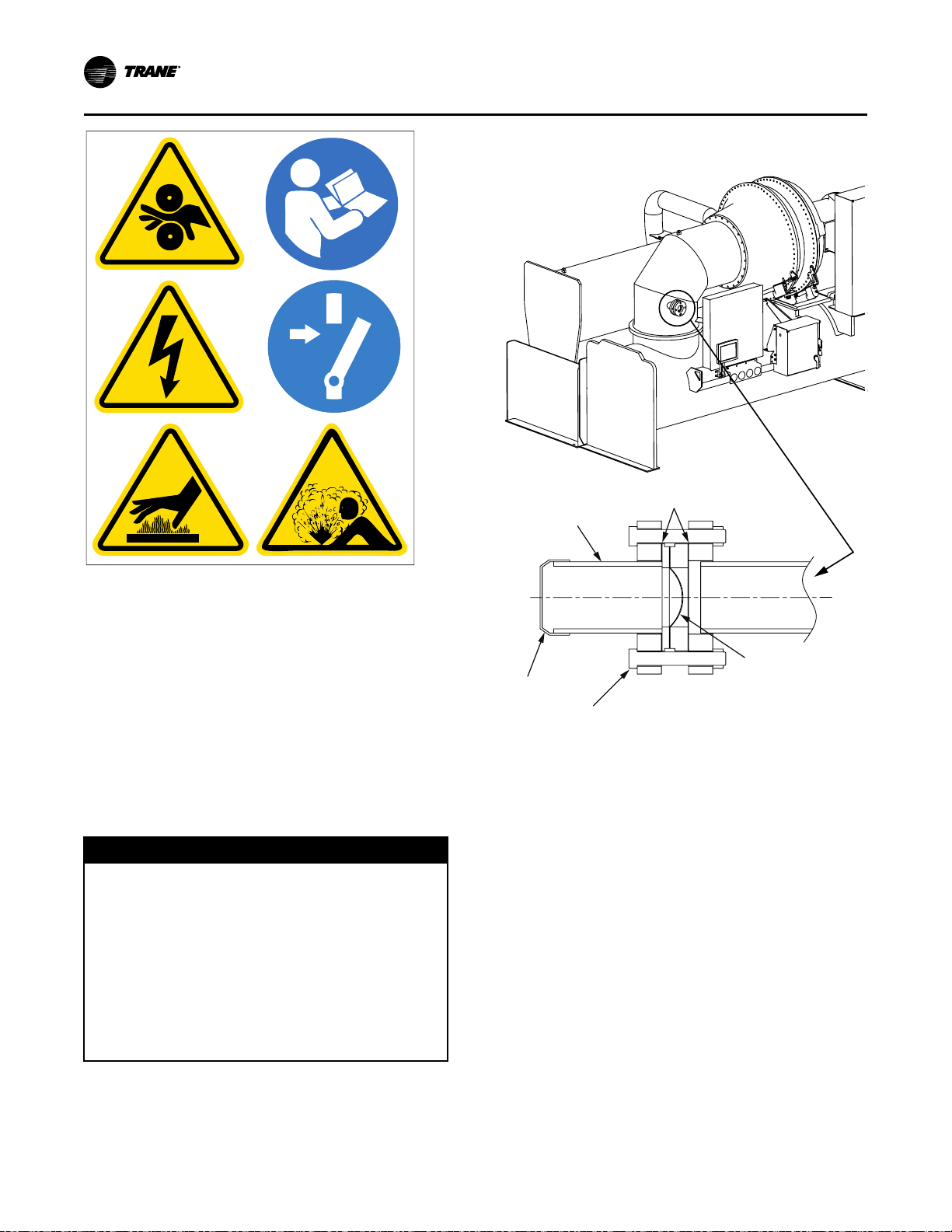
X39003892001A
Outside pipe
assembly
Gasket
Cap
Bolt
Rupture disk
Suction
connection
VVeenntt PPiippiinngg
Figure 24. Rupture disk location and cross section of
rupture disk
NNoottee:: Graphic labels (shown above) are used for CE
• Route the vent-line piping so that it discharges
• Provide a drip leg on the vent line (refer to the
EEqquuiippmmeenntt DDaammaaggee!!
FFaaiilluurree ttoo ffoollllooww iinnssttrruuccttiioonnss bbeellooww ccoouulldd rreessuulltt iinn
eeqquuiippmmeenntt ddaammaaggee..
AAllll vveenntt lliinneess mmuusstt bbee eeqquuiippppeedd wwiitthh aa ddrriipp lleegg ooff
ssuuffffiicciieenntt vvoolluummee ttoo hhoolldd tthhee eexxppeecctteedd
aaccccuummuullaattiioonn ooff wwaatteerr aanndd//oorr rreeffrriiggeerraanntt.. TThhee ddrriipp
lleegg mmuusstt bbee ddrraaiinneedd ppeerriiooddiiccaallllyy ttoo aassssuurree tthhaatt iitt
ddooeess nnoott oovveerrffllooww aanndd aallllooww fflluuiidd ttoo ffllooww iinnttoo tthhee
hhoorriizzoonnttaall ppoorrttiioonn ooff tthhee vveenntt lliinnee.. TTrraannee aassssuummeess
nnoo rreessppoonnssiibbiilliittyy ffoorr eeqquuiippmmeenntt ddaammaaggee ccaauusseedd bbyy
iinnssuuffffiicciieenntt ddrraaiinnaaggee ooff ddrriipp lleegg..
application only.
outdoors in an area that will not spray refrigerant
on anyone. Position the vent-line discharge at least
15 ft (4.6 m) above grade level and at least 20 ft
(6.1 m) from any building opening. Provide a ventline termination that cannot be blocked by debris or
accumulate rainwater.
following figure [arrangement for rupture disk relief
piping]). Provide a standard 1/4-in. FL x 1/4-in. NPT,
capped refrigerant service valve to facilitate liquid
removal.
NNOOTTIICCEE
NNoottee:: Pipe connection is 3 in. (76.2 mm) NPT.
• Consult local regulations and codes for any
additional relief line requirements.
38
CVHH-SVX001G-EN
Page 39

Alternate
Outside
wall
Support
this pipe
Purge discharge
vent line
Rupture disk
assembly
Flexible
steel
connection
1/4 in. FL x 1/4 in. NPT
drain valve
Drip leg
(length as required
for easy access)
Flow
Flow
Flow
FlowFlow
Chiller Chiller Chiller
Disk in normal
operating
position.
Chiller pressure
is below 50 psig
(344.7 kPaG).
When chiller
pressure
exceeds the
disk’s rated
burst pressure,
the disk begins
to tear open
along the score
line of the outlet
ring.
The disk snaps
open through
the score line of
the outlet ring
and the pressure
is vented. The
outlet ring is
designed with a
hinge area to
retain the disc
petal.
VVeenntt PPiippiinngg
Figure 25. Arrangement for rupture disk relief piping
IImmppoorrttaanntt:: On the purge discharge vent line, the purge
exhaust connection point MUST be lower
than the purge height. Do NOT create a Utrap; extend to drip leg if necessary to
avoid a trap.
Figure 26. Reverse buckling rupture disk (top view)
To prevent water, refrigerant, and/or other debris such
as rust from hindering the operation of the valve, a drip
leg should be installed immediately after or
downstream of the RuptureGuard™ (refer to the figure
in “Connection to External Vent Line and Drip Leg,” p.
39).
Connection to External Vent Line and Drip Leg
Trane RuptureGuard
General Information
The Trane RuptureGuard™ refrigerant containment
system replaces the carbon rupture disk on new low
pressure chillers utilizing R-1233zd. The
RuptureGuard™ consists of a solid-metal, (nonfragmenting) reverse-buckling rupture disk and
automatically re-seating relief valve. The relief valve
and the rupture disk are rated at the chiller’s maximum
working pressure level. If the chiller’s refrigerant
pressure exceeds the rupture disk burst rating, the disk
bursts, releasing pressure to the relief valve. The relief
valve vents the pressure down to a safe level and then
re-seats, thus minimizing the amount of refrigerant
vented to the atmosphere. The following figure
illustrates the operation of a reverse buckling rupture
disk.
CVHH-SVX001G-EN
NNOOTTIICCEE
EEqquuiippmmeenntt DDaammaaggee!!
FFaaiilluurree ttoo ffoollllooww iinnssttrruuccttiioonnss bbeellooww ccoouulldd rreessuulltt iinn
eeqquuiippmmeenntt ddaammaaggee..
AAllll vveenntt lliinneess mmuusstt bbee eeqquuiippppeedd wwiitthh aa ddrriipp lleegg ooff
ssuuffffiicciieenntt vvoolluummee ttoo hhoolldd tthhee eexxppeecctteedd
aaccccuummuullaattiioonn ooff wwaatteerr aanndd//oorr rreeffrriiggeerraanntt.. TThhee ddrriipp
lleegg mmuusstt bbee ddrraaiinneedd ppeerriiooddiiccaallllyy ttoo aassssuurree tthhaatt iitt
ddooeess nnoott oovveerrffllooww aanndd aallllooww fflluuiidd ttoo ffllooww iinnttoo tthhee
hhoorriizzoonnttaall ppoorrttiioonn ooff tthhee vveenntt lliinnee.. TTrraannee aassssuummeess
nnoo rreessppoonnssiibbiilliittyy ffoorr eeqquuiippmmeenntt ddaammaaggee ccaauusseedd bbyy
iinnssuuffffiicciieenntt ddrraaiinnaaggee ooff ddrriipp lleegg..
With RuptureGuard™ installed horizontally, the drain
plug downstream of the valve relief plug and nearest to
the bottom of the valve body should be piped to the
drip leg in the vent line (refer to the following figure).
This will allow the removal of any condensate formed
within the valve body.
Provisions, such as installing a set of flanges (refer to
the following figure) or other disconnect means, must
be made in the discharge vent piping. This will allow
the piping downstream of the valve to be easily
removed for an annual inspection, to replace the metal
RuptureGuard™ disk, or for any other servicing need.
1. Connect the discharge of the valve assembly to the
39
Page 40

Purge exhaust
Rupture disk
Flange
Inlet flange
Drain line
Outlet flange
Drain valve
VVeenntt PPiippiinngg
vent line connected to the outdoors.
NNoottee:: Make sure there are no crosses (a derate on
the rated flow capacity for this configuration
is published in Engineering Bulletin:
RuptureGuard Selection Guide [E/CTV-EB10]), elbows, tees, or any other obstructions
within the first 9 in. (22.86 cm) of valve
discharge. Refer to ASHRAE Standard 15,
national, state, and local codes for additional
requirements on piping rupture disk and
relief valve vent lines.
Figure 27. External vent line and drip leg (not
provided)
IImmppoorrttaanntt:: If a RuptureGuard™is to be installed, it
MUST be installed properly. Failure to
properly install the RuptureGuard
™
will
likely result in a start-up delays and
required rework and expenses that result
from a failure to properly install the
RuptureGuard
™
will NOT be paid by Trane.
Vent Line Sizing Reference
Table 13. “C” values used to determine rupture disk
NTON
900–1200 100M 100M 112.0 48.4 40.7 18.5 4.5
900–1200 100L 100L 123.2 54.5 45.8 18.5 4.5
900–1200 130M 130M 122.4 54.0 45.4 18.5 4.5
900–1200 160M 200M 134.1 60.5 50.7 18.5 4.5
900–1200 200L 220L 160.4 75.4 62.1 18.5 4.5
900–1200 220L 220L 168.6 83.6 62.1 18.5 4.5
1500–1700 200L 200L 156.8 75.4 57.1 19.8 4.5
1500–1700 220L 220L
900–1200 100M 10HM 127.0 48.4 55.7 18.5 4.5
900–1200 130M 13HM 138.2 54.0 61.3 18.5 4.5
900–1200 160M 20HM 150.2 60.5 66.8 18.5 4.5
1500–1700 200L 20HL 174.9 75.4 75.2 19.8 4.5
1500–1700 220L 22HL 191.4 83.6 83.6 19.8 4.5
Notes:
1. Rupture disk diameter is 3 in.
2. Use the total “C” value in the following figure to determine the
3. If piping multiple rupture disks (multiple units) to a common
4. The CVHH unit is a Simplex chiller and has (1) refrigerant circuit
vent line sizes (lb/min); for use with the
following figure
Evap.
Cond.
Size
(EVSZ)
vent line pipe diameter.
vent line, first determine the total “C” value for each unit, and
then; add all “C” values together and apply the result to the
following figure.
and (1) relief device.
(CDSZ)
“C” Values for Unit Components
Total
Size
Evap.
“C”
Value
169.9 83.6 62.1 19.8 4.5
Cond. Econ.
Oil
Tank
40
CVHH-SVX001G-EN
Page 41

Figure 28. Rupture disk vent pipe sizing (IP units); for use with preceding table
Pipe size as a Function of “C” Value and Length of Run
“C” Value (lb/min)
L = Pipe Length (Equivalent Feet)
Pipe Size (I.D.)
Friction Factor
6 NPS
6.06 in.
f = 0.0149
5 NPS
5.05 in.
f = 0.0155
4 NPS
4.03 in.
f = 0.0163
3 NPS
3.07 in.
f = 0.0173
1000
100
10
10 100 1000
VVeenntt PPiippiinngg
NNoottee:: The preceding figure, provided as a reference, is based on ASHRAE Standard 15. Vent line size is typically
dictated by state or local code which may be different from ASHRAE Standard 15 requirements.
CVHH-SVX001G-EN
41
Page 42

L =
0.214d5 (P
2
0
– P
2
2
)–d * ln(P0 / P2)
fC
2
R
6f
ASHRAE Standard 15
VVeenntt PPiippiinngg
• L = equivalent length of discharge piping, feet
= rated capacity as stamped on the relief device
• C
r
in SCFM (conversion: lb/min = SCFM * 0.0764)
= CC value in lb/min from the preceding table
C
r
• f = Moody friction factor in fully turbulent flow
• d = inside diameter of pipe or tube, in.
• ln = natural logarithm
• P
= absolute pressure at outlet of discharge piping,
2
psi (atmospheric pressure)
• P
= allowed back pressure (absolute) at the outlet
0
of pressure relief device, psi
P
= (0.15 P) + atmospheric pressure
0
Table 14. “C” values used to determine rupture disk
vent line sizes (kg/s); for use with the
following figure
Evap.
Cond.
NTON
900–1200 100M 100M 0.853 0.368 0.310 0.141 0.034
900–1200 100L 100L 0.939 0.415 0.349 0.141 0.034
900–1200 130M 130M 0.932 0.412 0.346 0.141 0.034
900–1200 160M 200M 1.022 0.461 0.386 0.141 0.034
900–1200 200L 220L 1.222 0.575 0.473 0.141 0.034
900–1200 220L 220L 1.284 0.637 0.473 0.141 0.034
1500–1700 200L 200L 1.195 0.575 0.435 0.151 0.034
1500–1700 220L 220L 1.295 0.637 0.473 0.151 0.034
900–1200 100M 10HM
900–1200 130M 13HM 1.053 0.412 0.467 0.141 0.034
900–1200 160M 20HM 1.144 0.461 0.509 0.141 0.034
1500–1700 200L 20HL 1.332 0.575 0.573 0.151 0.034
1500–1700 220L 22HL 1.458 0.637 0.637 0.151 0.034
Notes:
1. Rupture disk diameter is 76.2 mm.
2. Use the total “C” value in the following figure to determine the
vent line pipe diameter.
3. If piping multiple rupture disks (multiple units) to a common
vent line, first determine the total “C” value for each unit, and
then; add all “C” values together and apply the result to the
following figure .
4. The CVHH unit is a Simplex chiller and has (1) refrigerant circuit
and (1) relief device.
Size
(EVSZ)
(CDSZ)
“C” Values for Unit Components
Total
Size
Evap.
“C”
Value
0.967 0.368 0.424 0.141 0.034
Cond. Econ.
Oil
Tank
42
CVHH-SVX001G-EN
Page 43

Figure 29. Rupture disk vent pipe sizing (SI units); for use with preceding table
Pipe size as a Function of “C” Value and Length of Run
“C” Value (kg/s)
L = Pipe Length (Equivalent Meters)
Pipe Size (I.D.)
Friction Factor
150 DN
154 mm
f = 0.0149
125 DN
128 mm
f = 0.0155
100 DN
102 mm
f = 0.0163
80 DN
78 mm
f = 0.0173
10
1
0
10 100 1000
VVeenntt PPiippiinngg
NNoottee:: The preceding figure, provided as a reference, is based on ASHRAE Standard 15. Vent line size is typically
dictated by state or local code which may be different from ASHRAE Standard 15 requirements.
CVHH-SVX001G-EN
43
Page 44

L =
7.4381x10
5
(P
2
0
– P
2
2
)–d * ln(P0 / P2)
fC
2
R
500f
ASHRAE Standard 15
d
–15
VVeenntt PPiippiinngg
• L = equivalent length of discharge piping, meters
• C
= rated capacity as stamped on the relief device
r
in SCFM (conversion: kg/s = SCFM * 0.0764 / 132.28)
C
= CC value from the preceding table (convert C
r
in kg/s to lb/min for IP; lb/min = (kg/s) / 132.28)
• f = Moody friction factor in fully turbulent flow
• d = inside diameter of pipe or tube, mm
• ln = natural logarithm
• P
= absolute pressure at outlet of discharge piping,
2
kPa (atmospheric pressure)
• P
= allowed back pressure (absolute) at the outlet
0
of pressure relief device, kPa
P
= (0.15 P) + atmospheric pressure
0
44
CVHH-SVX001G-EN
Page 45

Insulation
Unit Insulation Requirements
Factory-installed insulation is available as an option for
all units. Factory installation does NOT include
insulation of the chiller feet; if required, insulation for
chiller feet is provided by others. In applications where
the chiller is not factory-insulated, install insulation
over the areas outlined and highlighted with dashed
lines as shown in the figure in “Factory Applied
Insulation,” p. 45.
Insulate all 1/4-in. (6.35-mm) eductor lines, one from
the suction cover and one from the evaporator, to
prevent sweating.
The quantities of insulation required based on unit size
and insulation thickness are listed in the following
table. Insulation thickness is determined at normal
design conditions which are:
• Standard comfort-cooling leaving chilled water
temperature
• 85°F (29.4°C) dry bulb ambient temperature
• 75 percent relative humidity
Operation outside of normal design conditions as
defined in this section may require additional
insulation; contact Trane for further review.
NNoottee:: If the unit is not factory-insulated, install
insulation around the evaporator bulbwells and
ensure that the bulbwells and connections for
the waterbox drains and vents are still accessible
after insulation is applied. The sensor modules
(Low Level Intelligent Devices [LLIDs]) and
interconnecting four-wire cable inter-processor
communication (IPC) bus must be raised up
above the field-installed insulation. Secure the
IPC bus to the insulation top/outer surface after
insulation is completed.
IImmppoorrttaanntt:: Do NOT insulate the motor housing, unit
wiring, or sensor modules.
WWAARRNNIINNGG
RReeppllaaccee MMaannuuaall iinn CCaabbiinneett AAfftteerr UUssee!!
FFaaiilluurree ttoo rreeppllaaccee tthhiiss IInnssttaallllaattiioonn,, OOppeerraattiioonn,, aanndd
MMaaiinntteennaannccee mmaannuuaall iinn ccaabbiinneett aafftteerr uussee ccoouulldd
pprreevveenntt ppeerrssoonnnneell ffrroomm aacccceessssiinngg nneecceessssaarryy
ssaaffeettyy iinnffoorrmmaattiioonn aanndd ccoouulldd rreessuulltt iinn ddeeaatthh oorr
sseerriioouuss iinnjjuurryy oorr eeqquuiippmmeenntt ddaammaaggee..
NNOOTTIICCEE
EEqquuiippmmeenntt DDaammaaggee!!
FFaaiilluurree ttoo rreemmoovvee tthhee ssttrraaiinn rreelliieeff wwiitthh tthhee sseennssoorr
ccoouulldd rreessuulltt iinn eeqquuiippmmeenntt ddaammaaggee..
DDoo NNOOTT aatttteemmpptt ttoo ppuullll sseennssoorr bbuullbb tthhrroouugghh tthhee
ssttrraaiinn rreelliieeff;; aallwwaayyss rreemmoovvee tthhee eennttiirree ssttrraaiinn rreelliieeff
wwiitthh tthhee sseennssoorr..
Table 15. Evaporator insulation requirements
EVSZ (Standard Unit)
100M 661 61.4
100L 680 63.2
130M 684 63.5
160M 711 66.1
200M 738 68.6
200L 765 71.1
220M 770 71.5
220L 799 74.2
Notes:
1. Units are NOT insulated on the motor or refrigerant drain lines.
2. 3/4-in. (19.05-mm) sheet insulation is installed on the
evaporator, evaporator waterboxes, suction elbow, suction cover,
economizer, liquid lines, and piping.
3. Copper oil eductor lines require pipe insulation.
3/4 in. (19.05 mm) Insulation
Square Feet Square Meters
Insulation Thickness Requirements
Factory Applied Insulation
All low-temperature surfaces are covered with 3/4 in.
(19.05 mm) Armaflex® II or equal (thermal conductivity
= 0.25 Btu/h-ft
waterboxes, suction elbow, economizer, and piping.
The insulation is Armaflex® or equivalent closed cell
elastomeric insulation to prevent the formation of
condensation in environments with a relative humidity
up to 75 percent. Chillers in high humidity areas or ice
storage, low leaving water temperature (less than 36°F
[2.2°C] chilled water temperature/glycol) units, may
require double thickness to prevent formation of
condensation.
IInnssuullaattiioonn DDaammaaggee!!
FFaaiilluurree ttoo ffoollllooww tthheessee iinnssttrruuccttiioonnss ccoouulldd rreessuulltt iinn
iinnssuullaattiioonn ddaammaaggee..
TToo pprreevveenntt ddaammaaggee ttoo ffaaccttoorryy iinnssttaalllleedd iinnssuullaattiioonn::
•• DDoo nnoott aallllooww tthhee iinnssuullaattiioonn ttoo bbee eexxppoosseedd ttoo
eexxcceessssiivvee ssuunnlliigghhtt.. SSttoorree iinnddoooorrss oorr ccoovveerr wwiitthh
ccaannvvaass ttoo pprreevveenntt eexxppoossuurree..
•• DDoo nnoott uussee tthhiinnnneerrss aanndd ssoollvveennttss oorr ootthheerr ttyyppeess
ooff ppaaiinntt.. UUssee oonnllyy wwaatteerr bbaassee llaatteexx..
2
[0.036 W/m2- K]), evaporator,
NNOOTTIICCEE
CVHH-SVX001G-EN
45
Page 46

Line from evaporator
Line to eductor
Filter drier
and eductor lines
Pipe (free cooling only)
Control
panel
support
Pipe
Economizer
Pipe
Suction
connection
See first
two notes
Suction
elbow
Evaporator
Suction
cover
See first
note
Eductor line
See first
two notes
IInnssuullaattiioonn
Figure 30. Recommended area for unit insulation
NNootteess::
• Bulbwells, drain, and vent connections must be accessible after insulating.
• All units with evaporator marine waterboxes wrap waterbox shell insulation with strapping and secure
strapping with seal.
• Evaporators with pressure vessel nameplates must have insulation cut out around the nameplate. Do NOT
glue insulation to the nameplate.
• Apply 2-in. (50.8-mm) wide black tape on overlap joints. Where possible apply 3-in. (7.6-cm) wide strip of
0.38-in. (9.7-mm) thick insulation over butt joint seams.
• Insulate all economizer supports.
46
CVHH-SVX001G-EN
Page 47

Installation: Controls
This section covers information pertaining to the
UC800 controller hardware. For information about the
Tracer® AdaptiView™ display, which is used to
interface with the internal chiller data and functions
provided by the UC800, refer to Tracer AdaptiView
Display for Water-Cooled CenTraVac Chillers
Operations Guide (CTV-SVU01*-EN).
UC800 Specifications
Power Supply
NNOOTTIICCEE
CCuussttoommeerr WWiirriinngg!!
FFaaiilluurree ttoo ffoollllooww iinnssttrruuccttiioonnss bbeellooww ccoouulldd rreessuulltt iinn
eeqquuiippmmeenntt oorr pprrooppeerrttyy--oonnllyy ddaammaaggee..
OOnnllyy uussee fflleexxiibbllee ccoonndduuiitt oorr mmeettaall--ccllaadd ccaabbllee wwhheenn
wwiirriinngg tthhee ccoonnttrrooll ppaanneell aanndd mmoottoorr tteerrmmiinnaall bbooxx ttoo
eennssuurree aa vviibbrraattiioonn--ffrreeee iinnssttaallllaattiioonn..
The UC800 (1K1) receives 24 Vac (210 mA) power from
the 1T3 power supply located in the chiller control
panel.
Wiring and Port Descriptions
The following figure illustrates the UC800 controller
ports, LEDs, rotary switches, and wiring terminals. The
numbered list following the figure corresponds to the
numbered callouts in the illustration.
CVHH-SVX001G-EN
47
Page 48

LINK
+ +
+
24
VDC
+
MBUS
1
2 3 4 5
6
7
8
9
0
-
6
0
-
Front View
Bottom View
IInnssttaallllaattiioonn:: CCoonnttrroollss
Figure 31. UC800 wiring locations and connection
ports
4. Machine bus for existing machine LLIDs (IPC3
Tracer bus). IPC3 Bus: used for Comm 4 using TCI
or LonTalk
5. Power (210 mA at 24 Vdc) and ground terminations
(same bus as Item 4). Factory wired.
6. Not used.
7. Marquee LED power and UC800 Status indicator
(refer to the table in “LED Description and
Operation,” p. 48).
8. Status LEDs for the BAS link, MBus link, and IMC
link.
9. USB device Type B connection for the service tool
(Tracer® TU).
10. The Ethernet connection can only be used with the
Tracer® AdaptiView™ display.
11. USB Host (not used).
®
using LCI-C.
Communication Interfaces
There are four connections on the UC800 that support
the communication interfaces listed. Refer to the figure
in “Wiring and Port Descriptions,” p. 47 for the
locations of each of these ports.
• BACnet® MS/TP
• MODBUS® Slave
• LonTalk® using LCI-C (from the IPC3 bus)
• Comm 4 using TCI (from the IPC3 bus)
1. Rotary Switches for setting BACnet® MAC address
2. LINK for BACnet® MS/TP, or MODBUS® Slave (two
3. LINK for BACnet® MS/TP, or MODBUS® Slave (two
48
or MODBUS® ID.
terminals, ±). Field wired if used.
terminals, ±). Field wired if used.
Rotary Switches
There are three rotary switches on the front of the
UC800 controller. Use these switches to define a threedigit address when the UC800 is installed in a BACnet®
or MODBUS® system (e.g., 107, 127, etc.).
NNoottee:: Valid addresses are 001 to 127 for BACnet
001 to 247 for MODBUS
®
.
®
and
LED Description and Operation
There are ten LEDs on the front of the UC800. The
following figure shows the locations of each LED and
the following table describes their behavior in specific
instances.
CVHH-SVX001G-EN
Page 49
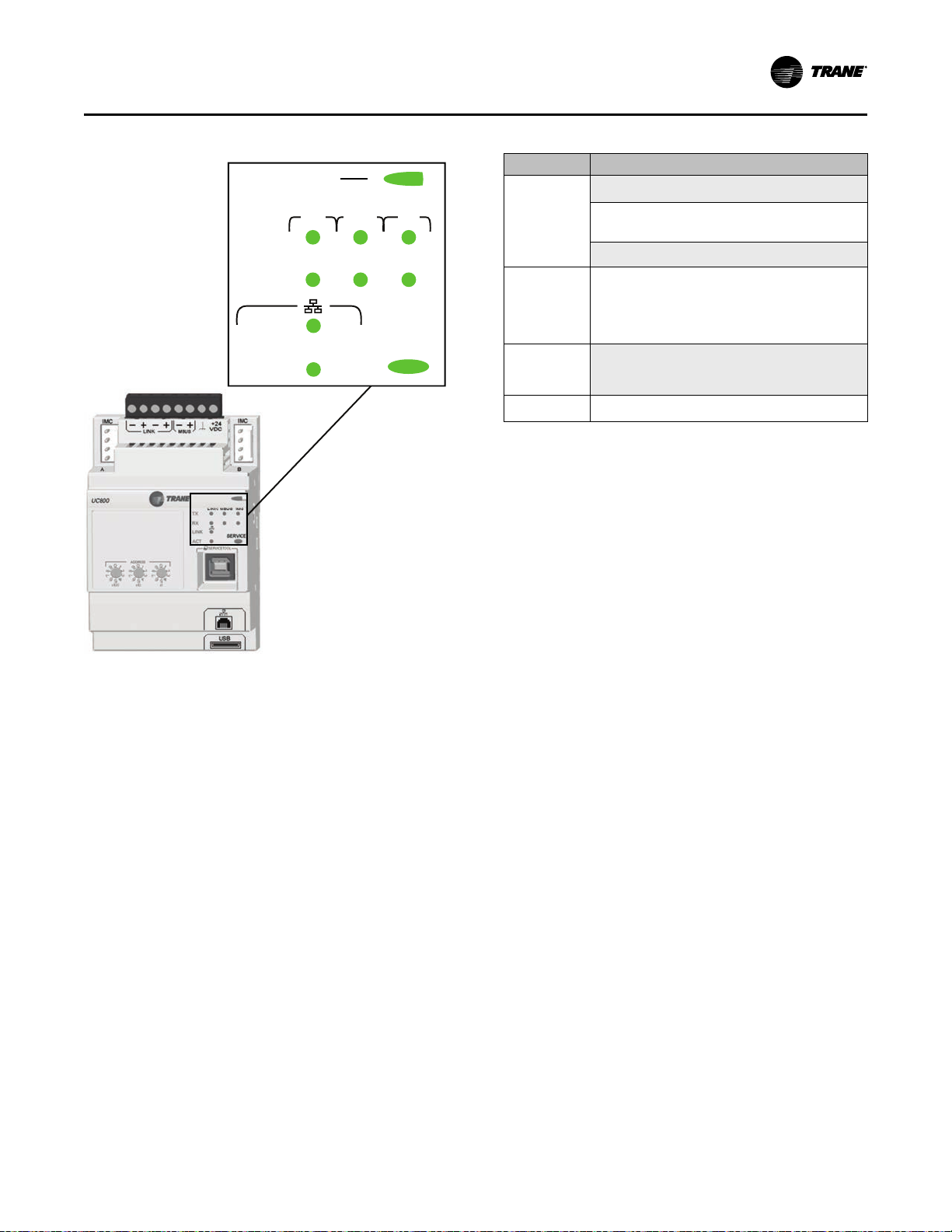
LINK
LINK MBUS IMC
TX
RX
ACT
SERVICE
Marquee LED
IInnssttaallllaattiioonn:: CCoonnttrroollss
Figure 32. LED locations
Table 16. LED behavior
LED UC800 Status
Powered. If the Marquee LED is green solid, the
UC800 is powered and no problems exist.
Marquee LED
LINK, MBUS,
IMC
Ethernet Link
Service
Low power or malfunction. If the Marquee LED
is red solid, the UC800 is powered but there are
problems present.
Alarm. The Marquee LED blinks red when an alarm
exists.
The TX LED blinks green at the data transfer rate
when the UC800 transfers data to other devices on
the link.
The RX LED blinks yellow at the data transfer rate
when the UC800 receives data from other devices
on the link.
The LINK LED is solid green if the Ethernet link is
connected and communicating.
The ACT LED blinks yellow at the data transfer rate
when data flow is active on the link.
The Service LED is solid green when pressed. For
qualified service technicians only. Do NOT use.
IImmppoorrttaanntt:: Maintain at least 6 in. (16 cm) between low-
voltage (less than 30V) and high voltage
circuits. Failure to do so could result in
electrical noise that could distort the
signals carried by the low-voltage wiring,
including inter-processor communication
(IPC).
CVHH-SVX001G-EN
49
Page 50

30 Volt Maximum
30–120 Volt Maximum
IInnssttaallllaattiioonn:: CCoonnttrroollss
Figure 33. Control panel: Tracer®® AdaptiView™™ main unit assembly (showing low voltage and higher voltage areas
for proper routing of field wiring)
50
CVHH-SVX001G-EN
Page 51
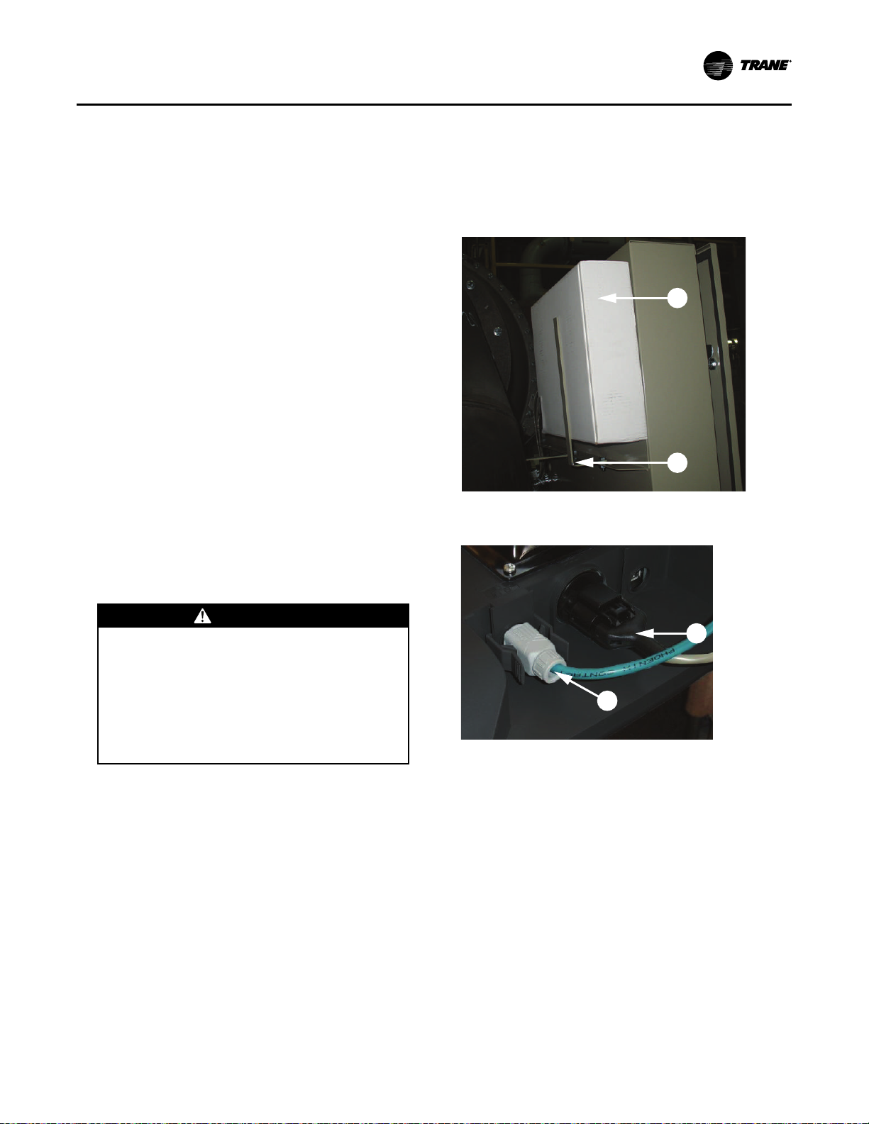
A
B
D
C
IInnssttaallllaattiioonn:: CCoonnttrroollss
Installing the Tracer AdaptiView Display
During shipment, the Tracer® AdaptiView™ display is
boxed, shrink-wrapped, and located behind the control
panel. The display must be installed at the site.
IImmppoorrttaanntt:: For best results, Trane, or an agent of
Trane, must install the Tracer
AdaptiView™display and display arm.
1. Unwrap the control panel and display arm. Locate
the box containing the Tracer® AdaptiView™
display behind the control panel (labeled A in the
following figure).
2. After the box containing the display has been
removed, remove the shipping bracket from the
back of the control panel (labeled B in the following
figure).
3. Remove the display from the box.
NNoottee:: Screws are M4 (metric size 4), 6 to 8 mm long,
and are shipped with the display.
4. Plug the power cable (labeled C in the following
figure) and the Ethernet cable (labeled D in the
following figure) into the bottom of the display.
NNoottee:: Both cables are already present and extend
from the end of the display arm.
5. Adjust the Tracer® AdaptiView™ display support
arm so the base plate that attaches to the display is
horizontal.
®
holes in the display support arm base plate.
8. Attach the Tracer® AdaptiView™ display to the
display support arm base plate (labeled E in the
following figure) using the M4 (metric size 4)
screws referenced in Step 3.
Figure 34. Tracer®® AdaptiView™™ shipping location
Figure 35. Power cable and Ethernet cable
connections
CCAAUUTTIIOONN
TTeennssiioonn iinn DDiissppllaayy SSuuppppoorrtt AArrmm!!
FFaaiilluurree ttoo ffoollllooww iinnssttrruuccttiioonnss bbeellooww ccoouulldd
rreessuulltt iinn uunneexxppeecctteedd mmoovveemmeenntt ooff tthhee sspprriinngg-llooaaddeedd ssuuppppoorrtt aarrmm wwhhiicchh ccoouulldd rreessuulltt iinn mmiinnoorr
ttoo mmooddeerraattee iinnjjuurryy..
EEnnssuurree tthhaatt tthhee ssuuppppoorrtt aarrmm iiss iinn tthhee ffuullll
uupprriigghhtt ppoossiittiioonn wwhheenn rreemmoovviinngg tthhee TTrraacceerr
AAddaappttiiVViieeww ddiissppllaayy ffrroomm tthhee ssuuppppoorrtt aarrmm..
NNoottee:: Review “Adjusting the Tracer AdaptiView
Display Arm,” p. 52 before attaching the
display as some adjustments may be
required prior to attaching the display to the
support arm base.
6. Position the Tracer® AdaptiView™ display—with
the LCD screen facing up—on top of the display
support arm base plate.
NNoottee:: Ensure the Trane logo is positioned so that it
will be at the top when the display is attached
to the display support arm.
IImmppoorrttaanntt:: Use care when positioning the Tracer
AdaptiView™display on top of the support
arm base plate and do NOT drop the
display.
7. Align the four holes in the display with the screw
®
CVHH-SVX001G-EN
51
Page 52

E
1
2
3
4
IInnssttaallllaattiioonn:: CCoonnttrroollss
Figure 36. Display attachments to the support arm
base plate
Adjusting the Tracer AdaptiView Display Arm
The Tracer® AdaptiView™ display arm may become
too loose or too tight and may need adjustment. There
are three joints on the display arm that allow the
display to be positioned at a variety of heights and
angles (refer to items labeled 11, 22, and 33 in the
following figure).
Figure 37. Joint locations on the display arm
To adjust the tension on the display arm:
• At each joint in the display arm, there is either a hex
bolt (11 and 22) or hex screw (33). Turn the hex bolt or
screw in the proper direction to increase or
decrease tension.
NNoottee:: Each hex bolt or screw is labeled with
lloooosseenn/ttiigghhtteenn or ++/-- indicators.
• Joint 33 has a 6 mm hex screw controlling the
tension on a gas spring, which allows the Tracer®
AdaptiView™ display to tilt up and down.
• Joints 11 and 22 are covered by a plastic cap. Remove
the plastic cap to access the screw. Adjust using a
13 mm wrench as necessary.
• To adjust the swivel rotation tension of the Tracer®
AdaptiView™ display, adjust the screw located in
the support arm base plate, as described in the final
step in “Installing the Tracer AdaptiView
Display,” p. 51. This adjustment must be done prior
to attaching the display to the support arm base.
Use a 14 mm wrench to adjust the tension.
• To adjust the left/right swivel of the entire display
arm, use a 13 mm wrench to adjust the screw
labeled 44 in the preceding figure.
52
CVHH-SVX001G-EN
Page 53

Electrical Requirements
X39003892001A
Installation Requirements
WWAARRNNIINNGG
PPrrooppeerr FFiieelldd WWiirriinngg aanndd GGrroouunnddiinngg
RReeqquuiirreedd!!
FFaaiilluurree ttoo ffoollllooww ccooddee ccoouulldd rreessuulltt iinn ddeeaatthh oorr
sseerriioouuss iinnjjuurryy..
AAllll ffiieelldd wwiirriinngg MMUUSSTT bbee ppeerrffoorrmmeedd bbyy qquuaalliiffiieedd
ppeerrssoonnnneell.. IImmpprrooppeerrllyy iinnssttaalllleedd aanndd ggrroouunnddeedd
ffiieelldd wwiirriinngg ppoosseess FFIIRREE aanndd EELLEECCTTRROOCCUUTTIIOONN
hhaazzaarrddss.. TToo aavvooiidd tthheessee hhaazzaarrddss,, yyoouu MMUUSSTT ffoollllooww
rreeqquuiirreemmeennttss ffoorr ffiieelldd wwiirriinngg iinnssttaallllaattiioonn aanndd
ggrroouunnddiinngg aass ddeessccrriibbeedd iinn NNEECC aanndd yyoouurr llooccaall//
ssttaattee//nnaattiioonnaall eelleeccttrriiccaall ccooddeess..
• power supply wiring to the starter,
• other unit control options present, and
• any field-supplied control devices.
As you review this manual along with the wiring
instructions presented in this section, keep in mind
that:
• All field-installed wiring must conform to National
Electric Code (NEC) guidelines, and any applicable
local, state, and national codes. For the USA, be
sure to satisfy proper equipment grounding
requirements per NEC.
• Compressor motor and unit electrical data
(including motor kW, voltage utilization range,
rated load amps, and locked rotor amps) is listed on
the chiller nameplate.
• All field-installed wiring must be checked for proper
terminations, and for possible shorts or grounds.
NNoottee:: Always refer to the actual wiring diagrams
that shipped with the chiller or the unit
submittal for specific as-built electrical
schematic and connection information.
NNOOTTIICCEE
AAddaappttiivvee FFrreeqquueennccyy DDrriivvee ((AAFFDD))//
SSttaarrtteerr CCoommppoonneenntt DDaammaaggee!!
FFaaiilluurree ttoo rreemmoovvee ddeebbrriiss ffrroomm iinnssiiddee tthhee AAFFDD//
ssttaarrtteerr ppaanneell ccoouulldd rreessuulltt iinn aann eelleeccttrriiccaall sshhoorrtt aanndd
ccoouulldd ccaauussee sseerriioouuss AAFFDD//ssttaarrtteerr ccoommppoonneenntt
ddaammaaggee..
NNoottee:: Graphic labels (shown above) are used for CE
application only.
IImmppoorrttaanntt::
• Before servicing, disconnect all power
sources and allow at least 30 minutes
for capacitors to discharge.
• All electrical enclosures—unit or remote
—are IP2X.
Unit-mounted starters are available as an option on
most units. While this option eliminates most fieldinstalled wiring requirements, the electrical contractor
must still complete the electrical connection for the
following:
CVHH-SVX001G-EN
Do NOT modify or cut enclosure to provide electrical
access. Removable panels have been provided, and
any modification should be done away from the
enclosure. If the starter enclosure must be cut to
provide electrical access, exercise care to prevent
debris from falling inside the enclosure. Refer to
installation information shipped with the starter or
submittal drawings.
Electrical Requirements
Before wiring begins, observe the following electrical
requirements:
• Follow all lockout/tagout procedures prior to
performing installation and/or service on the unit.
• Always wear appropriate personal protective
equipment.
• Wait the required time to allow the capacitor(s) to
discharge; this could be up to 30 minutes.
• Verify that all capacitors are discharged prior to
service using a properly rated volt meter.
• Use appropriate capacitor discharge tool when
necessary.
53
Page 54
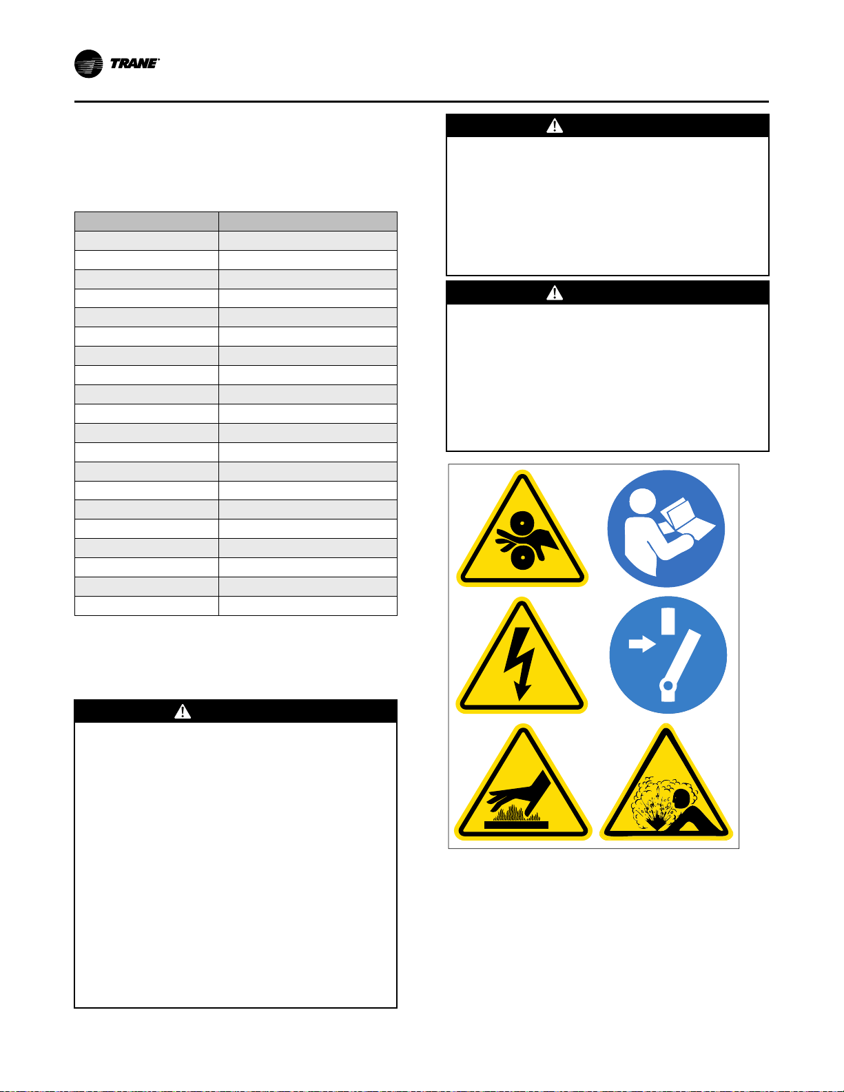
X39003892001A
EElleeccttrriiccaall RReeqquuiirreemmeennttss
• Comply with the safety practices recommended in
PROD-SVB06*-EN.
For AWG/MCM equivalents in mm
2
, refer to the
following table.
Table 17. Wire sizing reference
2
AWG/MCM mm
22 0.32
21 0.35
20 0.5
18 0.75
17 1.0
16 1.5
14 2.5
12 4
10 6
8 10
6 16
4 25
2 or 1 35
1/0
2/0
2/0 or 3/0
4/0 or 250
300 150
350 or 400 185
450 or 500 240
Note: AWG = American Wire Gauge
Equivalent
50
70
95
120
WWAARRNNIINNGG
PPeerrssoonnaall PPrrootteeccttiivvee EEqquuiippmmeenntt ((PPPPEE))
RReeqquuiirreedd!!
FFaaiilluurree ttoo wweeaarr PPPPEE aanndd ffoollllooww pprrooppeerr hhaannddlliinngg
gguuiiddeelliinneess ccoouulldd rreessuulltt iinn ddeeaatthh oorr sseerriioouuss iinnjjuurryy..
AAllwwaayyss wweeaarr aapppprroopprriiaattee ppeerrssoonnaall pprrootteeccttiivvee
eeqquuiippmmeenntt iinn aaccccoorrddaannccee wwiitthh aapppplliiccaabbllee
rreegguullaattiioonnss aanndd//oorr ssttaannddaarrddss ttoo gguuaarrdd aaggaaiinnsstt
ppootteennttiiaall eelleeccttrriiccaall sshhoocckk aanndd ffllaasshh hhaazzaarrddss..
WWAARRNNIINNGG
LLiivvee EElleeccttrriiccaall CCoommppoonneennttss!!
FFaaiilluurree ttoo ffoollllooww aallll eelleeccttrriiccaall ssaaffeettyy pprreeccaauuttiioonnss
wwhheenn eexxppoosseedd ttoo lliivvee eelleeccttrriiccaall ccoommppoonneennttss ccoouulldd
rreessuulltt iinn ddeeaatthh oorr sseerriioouuss iinnjjuurryy..
WWhheenn iitt iiss nneecceessssaarryy ttoo wwoorrkk wwiitthh lliivvee eelleeccttrriiccaall
ccoommppoonneennttss,, hhaavvee aa qquuaalliiffiieedd lliicceennsseedd eelleeccttrriicciiaann
oorr ootthheerr iinnddiivviidduuaall wwhhoo hhaass bbeeeenn pprrooppeerrllyy ttrraaiinneedd
iinn hhaannddlliinngg lliivvee eelleeccttrriiccaall ccoommppoonneennttss ppeerrffoorrmm
tthheessee ttaasskkss..
IImmppoorrttaanntt:: Customers are responsible for all field
wiring in compliance with international,
national, and/or local codes.
WWAARRNNIINNGG
HHaazzaarrddoouuss VVoollttaaggee ww//CCaappaacciittoorrss!!
FFaaiilluurree ttoo ddiissccoonnnneecctt ppoowweerr aanndd ddiisscchhaarrggee
ccaappaacciittoorrss bbeeffoorree sseerrvviicciinngg ccoouulldd rreessuulltt iinn ddeeaatthh oorr
sseerriioouuss iinnjjuurryy..
DDiissccoonnnneecctt aallll eelleeccttrriicc ppoowweerr,, iinncclluuddiinngg rreemmoottee
ddiissccoonnnneeccttss aanndd ddiisscchhaarrggee aallll mmoottoorr ssttaarrtt//rruunn
ccaappaacciittoorrss bbeeffoorree sseerrvviicciinngg.. FFoollllooww pprrooppeerr
lloocckkoouutt//ttaaggoouutt pprroocceedduurreess ttoo eennssuurree tthhee ppoowweerr
ccaannnnoott bbee iinnaaddvveerrtteennttllyy eenneerrggiizzeedd.. FFoorr vvaarriiaabbllee
ffrreeqquueennccyy ddrriivveess oorr ootthheerr eenneerrggyy ssttoorriinngg
ccoommppoonneennttss pprroovviiddeedd bbyy TTrraannee oorr ootthheerrss,, rreeffeerr ttoo
tthhee aapppprroopprriiaattee mmaannuuffaaccttuurreerr’’ss lliitteerraattuurree ffoorr
aalllloowwaabbllee wwaaiittiinngg ppeerriiooddss ffoorr ddiisscchhaarrggee ooff
ccaappaacciittoorrss.. VVeerriiffyy wwiitthh aa CCAATT IIIIII oorr IIVV vvoollttmmeetteerr
rraatteedd ppeerr NNFFPPAA 7700EE tthhaatt aallll ccaappaacciittoorrss hhaavvee
ddiisscchhaarrggeedd..
FFoorr aaddddiittiioonnaall iinnffoorrmmaattiioonn rreeggaarrddiinngg tthhee ssaaffee
ddiisscchhaarrggee ooff ccaappaacciittoorrss,, sseeee PPRROODD--SSVVBB0066**--EENN..
54
NNoottee:: Graphic labels (shown above) are used for CE
application only.
IImmppoorrttaanntt::
• Before servicing, disconnect all power
sources and allow at least 30 minutes
for capacitors to discharge.
• All electrical enclosures—unit or remote
—are IP2X.
CVHH-SVX001G-EN
Page 55

EElleeccttrriiccaall RReeqquuiirreemmeennttss
Trane-supplied Remote Starter Wiring
Table 18. Standard field power wiring requirements
Power Supply Wiring
to Starter Panel
3-Phase Line Voltage L1, L2, L3, and Ground
Starter to Motor Power Wiring
Remote Starter to Chiller Motor Junction Box
Power Supply Wiring to Unit-Mounted
Control Power Transformer
(CPTR Optional)
3-Phase Line Voltage
(b)
Ground CPTR Panel GND
Starter to Control Panel
120 Vac Control Wiring
120 Vac Power Supply (from Starter to
Control Panel)
High Pressure Cutout to Starter
1F1 Circuit Breaker to Starter 2X8-3 1X1-2
Oil Pump Interlock 2X8-7, 2X8-8 1X1-10, 1X1-21
Low-voltage Starter Oil/Refrigerant Pump
Mdeium-voltage Starter Oil/Refrigerant
Start
Pump Start
Oil/Refrigerant Pump Neutral
Starter to Oil/Refrigerant Pump
Junction Box
Low Voltage 3-Phase Pump Power 2X8-21, 2X8-22, 2X8-23 4X4-1, 4X4-2, 4X4-3
Medium Voltage 1-Phase Pump Power 2X8-12, 2X8-13 4X4-1, 4X4-4
Low Voltage Circuits
Less Than 30 Vac
Standard Circuits
Inter-processor Communications (IPC)
Remote-Mounted
Notes:
1. All wiring to be in accordance with National Electrical Code (NEC) and any local codes.
2. For AWG/MCM equivalents in mm
3. Auxiliary equipment must be powered from other sources as the chiller control panel power supplies are sized for the chiller loads only.
(a)
Ground lug for a unit-mounted solid state starter or wye-delta starter is sized to accept 14 AWG solid to 8 AWG strand wire. If local codes require different
lug size, it must be field-supplied and -installed.
(b)
Refer to submittal and ship-with wiring schematics for voltage requirements.
(c)
Must be separated from 120 Vac and higher wiring.
(d)
The maximum distance a Trane–supplied remote starter can be placed from the chiller is 1000 ft (305 m).
(c) (d)
2
, refer to the table in “Electrical Requirements,” p. 53.
Starter Panel
Terminals
(a)
Starter Motor
T1 through T6 T1 through T6
Control Power Transformer
Terminals
6Q1-1,3,5
Starter Panel
Terminals
2X8-1, 2X8-2
2X8-G (Ground)
2X8-4 1X1-4
2X8-24 1X1-21
2X8-14 1X1-21
2X8-25 1X1-16
Starter Panel
Terminals
Starter Panel
Terminals
2K32-J3-3-4, or
2X1-12 to 13 if Present (Do
NOT Ground Shield at Starter)
Unit Control Panel
Terminations
1X1-1, 1X1-12
1X1-G (Ground)
Oil/Refrigerant
Pump Junction Box
Unit Control Panel
Terminations
1T2-J53-4
Shield Ground at
1X1-G (GND) Only
2-wire with Gound
Comm Link
CVHH-SVX001G-EN
55
Page 56

Customer-supplied Remote Starter Wiring
Table 19. Standard customer-supplied remote field wiring requirements
Power Supply Wiring to Starter Panel
Starter by Others 3-phase Power Wiring See Starter by Others Schematic
Starter to Motor Power Wiring
Remote Starter to Chiller Motor Junction box
(a)
Power Supply Wiring to Unit-Mounted Control
Power Transformer (CPTR)
3-Phase line voltage
(b)
Ground CPTR Panel GND
Starter to Control Panel 120 Vac Control Wiring
Power from Control Panel 1F1 5X12-3 1X1-2
Neutral from Control Panel 5X12-2 1X1-13
Ground from Control Panel 5X12-G 1X1-G
Interlock Relay Signal
Start Contactor Signal
Oil Pump Interlock 5X12-7, 5X12-8 1X1-10, 1X1-21
Run Contactor Signal
Transition Complete
Solid State Starter Fault
(c)
Low Voltage Circuits less than 30 Vac
Standard Circuits
Current Transformers (refer to table in “Current
Transformer and Potential Transformer Wire
Sizing,” p. 57) (Required)
(d)
Potential Transformers (Required)
Notes:
1. All wiring to be in accordance with National Electrical Code (NC) and any local codes.
2. For AWG/MCM equivalents in mm
3. Starter by Others Specification available from your local Trane sales office.
(a)
Wires, lugs, and fuses/breakers are sized based on National Electric Code (NEC) [NFPA 70] and UL 1995.
(b)
Refer to submittal and ship-with wiring schematics for voltage requirements.
(c)
Solid State Starter Fault input is used with low- and medium-voltage, customer-supplied solid state starters only.
(d)
Must be separated from 120 Vac and higher wiring.
2
, refer to the table in “Electrical Requirements,” p. 53.
Starter Panel Terminals
Starters Motor
T1 through T6 Terminals T1 through T6 Terminals
Control Power Transformer
Terminals
6Q1-1,3,5
Starter Panel Terminals
Unit Control Panel
Terminations
5X12-4 1K23 J10-1
5X12-5 1K23 J8-1
5X12-10 1K23 J6-1
5X12-14 1K23 J12-2
5X12-12
5X12-11
Starter Panel Terminals
1K13 J2-2
1K13 J2-1
Unit Control Panel
Terminations
5X12-19 1K23 J7-1
5X12-20 1K23 J7-2
5X12-21 1K23 J7-3
5X12-22 1K23 J7-4
5X12-23 1K23 J7-5
5X12-24 1K23 J7-6
5X12-25 1K23 J5-1
5X12-26 1K23 J5-2
5X12-27 1K23 J5-3
5X12-28 1K23 J5-4
5X12-29 1K23 J5-5
5X12-30 1K23 J5-6
Note: Phasing Must be
Maintained
56
CVHH-SVX001G-EN
Page 57
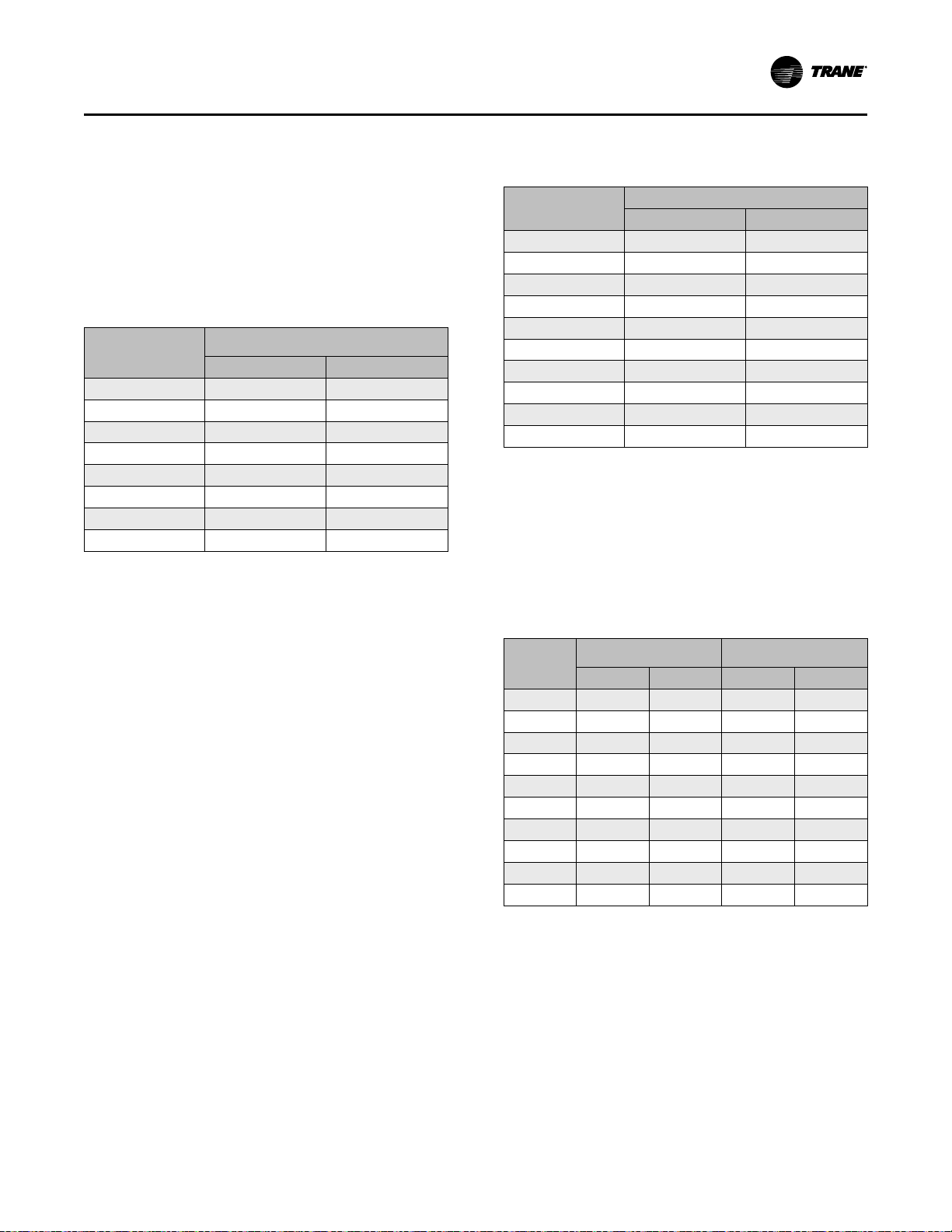
CCuussttoommeerr--ssuupppplliieedd RReemmoottee SSttaarrtteerr WWiirriinngg
Current Transformer and Potential Transformer Wire Sizing
For customer-supplied starter-to-chiller unit control
panel starter module 1K23; these wires must be
separated from 120 Vac or higher wiring.
Table 20. Maximum recommended wire length for
Wire AWG
Notes:
1. For AWG/MCM equivalents in mm
2. Wire length is for copper conductors only.
3. Wire length is total one-way distance that the CT can be from
(a)
Wires, lugs, and fuses/breakers are sized based on National Electric
Code (NEC) [NFPA 70] and UL 1995.
secondary current transformer (CT) leads in
dual CT system
Maximum Wire Length
(a)
8 1362.8 415.5
10 856.9 261.2
12 538.9 164.3
14 338.9 103.3
16 213.1 65.0
17 169.1 51.5
18 134.1 40.9
20 84.3 25.7
“Electrical Requirements,” p. 53.
the starter module.
Secondary CT Leads
Feet Meters
2
, refer to the table in
Table 21. Maximum recommended total wire length
for potential transformers (PTs) in a single
PT system
Wire AWG
Notes:
1. For AWG/MCM equivalents in mm
“Electrical Requirements,” p. 53.
2. Wire length is for copper conductors only.
3. Wire length is maximum round trip wire length. The maximum
distance the PT can be located from the starter module is half of the
listed value.
(a)
Wires, lugs, and fuses/breakers are sized based on National Electric
Code (NEC) [NFPA 70] and UL 1995.
(a)
8 5339 1627
10 3357 1023
12 2112 643
14 1328 404
16 835 254
17 662 201
18 525 160
20 330 100
21 262 79
22 207 63
Maximum Lead Length
Feet Meters
2
, refer to the table in
Table 22. Maximum recommended total wire length
(to and from) for PT leads in a dual PT
system
Wire AWG
(a)
8 3061 933 711 217
10 1924 586 447 136
12 1211 369 281 85
14 761 232 177 53
16 478 145 111 33
17 379 115 88 26
18 301 91 70 21
20 189 57 44 13
21 150 45 34 10
22 119 36 27 8
Notes:
1. For AWG/MCM equivalents in mm
“Electrical Requirements,” p. 53.
2. Wire length is for copper conductors only.
3. Wire length is maximum round trip wire length. The maximum
distance the PT can be located from the starter module is half of the
listed value.
(a)
Wires, lugs, and fuses/breakers are sized based on National Electric
Code (NEC) [NFPA 70] and UL 1995.
Max Wire Length
Primary
Feet Meters Feet Meters
Max Wire Length
Secondary
2
, refer to the table in
CVHH-SVX001G-EN
57
Page 58

Power Supply Wiring
X39003892001A
WWAARRNNIINNGG
PPrrooppeerr FFiieelldd WWiirriinngg aanndd GGrroouunnddiinngg
RReeqquuiirreedd!!
FFaaiilluurree ttoo ffoollllooww ccooddee ccoouulldd rreessuulltt iinn ddeeaatthh oorr
sseerriioouuss iinnjjuurryy..
AAllll ffiieelldd wwiirriinngg MMUUSSTT bbee ppeerrffoorrmmeedd bbyy qquuaalliiffiieedd
ppeerrssoonnnneell.. IImmpprrooppeerrllyy iinnssttaalllleedd aanndd ggrroouunnddeedd
ffiieelldd wwiirriinngg ppoosseess FFIIRREE aanndd EELLEECCTTRROOCCUUTTIIOONN
hhaazzaarrddss.. TToo aavvooiidd tthheessee hhaazzaarrddss,, yyoouu MMUUSSTT ffoollllooww
rreeqquuiirreemmeennttss ffoorr ffiieelldd wwiirriinngg iinnssttaallllaattiioonn aanndd
ggrroouunnddiinngg aass ddeessccrriibbeedd iinn NNEECC aanndd yyoouurr llooccaall//
ssttaattee//nnaattiioonnaall eelleeccttrriiccaall ccooddeess..
NNoottee:: Graphic labels (shown above) are used for CE
application only.
IImmppoorrttaanntt::
• Before servicing, disconnect all power
sources and allow at least 30 minutes
for capacitors to discharge.
• All electrical enclosures—unit or remote
—are IP2X.
Three-Phase Power
Review and follow the guidelines in this section to
properly install and connect the power supply wiring to
the starter panel:
• Verify that the starter nameplate ratings are
compatible with the power supply characteristics
and with the electrical data on the unit nameplate.
NNOOTTIICCEE
AAddaappttiivvee FFrreeqquueennccyy DDrriivvee ((AAFFDD))//
SSttaarrtteerr CCoommppoonneenntt DDaammaaggee!!
FFaaiilluurree ttoo rreemmoovvee ddeebbrriiss ffrroomm iinnssiiddee tthhee AAFFDD//
ssttaarrtteerr ppaanneell ccoouulldd rreessuulltt iinn aann eelleeccttrriiccaall sshhoorrtt aanndd
ccoouulldd ccaauussee sseerriioouuss AAFFDD//ssttaarrtteerr ccoommppoonneenntt
ddaammaaggee..
NNOOTTIICCEE
UUssee CCooppppeerr CCoonndduuccttoorrss OOnnllyy!!
FFaaiilluurree ttoo uussee ccooppppeerr ccoonndduuccttoorrss ccoouulldd rreessuulltt iinn
eeqquuiippmmeenntt ddaammaaggee aass tthhee eeqquuiippmmeenntt wwaass nnoott
ddeessiiggnneedd oorr qquuaalliiffiieedd ttoo aacccceepptt ootthheerr ttyyppeess ooff
ccoonndduuccttoorrss..
• Do NOT modify or cut enclosure to provide
electrical access. Removable panels have been
provided and any modification should be done
away from the enclosure. If the starter enclosure
must be cut to provide electrical access, exercise
care to prevent debris from falling inside the
enclosure.
• Use copper conductors to connect the three-phase
power supply to the remote- or unit-mounted
starter panel.
• Flexible conduit connections are recommended to
enhance serviceability and minimize vibration
transmission.
• Size the power supply wiring in accordance with
National Electric Code (NEC) and local guidelines,
using the RLA value stamped on the chiller
nameplate and transformer load on L1 and L2.
• Confirm that wire size is compatible with lug size
stated in unit submittal.
• Make sure that the incoming power wiring is
properly phased; each power supply conduit run to
the starter must carry the correct number of
conductors to ensure equal phase representation.
NNoottee:: Connect L1, L2, and L3 (shown in the
following figure) per starter diagram
provided with chiller.
• When installing the power supply conduit, ensure
that the position of the conduit does not interfere
with the serviceability of any of the unit
components, or with structural members and
equipment. Ensure that the conduit is long enough
to simplify any servicing that may be necessary in
the future (e.g., starter).
• Electrical wire torque specifications—follow starter
manufacturer’s torque specifications.
58
CVHH-SVX001G-EN
Page 59

L1
L2 L3
G
L1
L2 L3
G
L1
L2 L3
G
G G
L1 L2 L3 L1 L2 L3
L3
L2 L1
G
L3
L2 L1
G
L3
L2 L1
G
G G
L3 L2 L1 L3 L2 L1
Unit-mounted Starters
Remote-mounted Starters
PPoowweerr SSuuppppllyy WWiirriinngg
Figure 38. Proper phasing for starter power supply
wiring
Circuit Breakers and Fused Disconnects
Any field-supplied circuit breaker or fused disconnect
installed in power supplied to the chiller must be sized
in compliance with National Electric Code (NEC) or
local guidelines.
CE for Control Power Transformer Option
IImmppoorrttaanntt:: For the Control Power Transformer (CPTR)
option, chiller-mounted/UPS power, the
customer needs to ensure that the supply is
NOT taken from public low voltage
supplies, and that a dedicated clean source
of private power supply is used for chillermounted CPTR option when a CE chiller is
selected. This also includes when CPTR
option is standard such as in customersupplied starters and remote-mounted
medium-voltage Adaptive Frequency
Drives (AFDs).
All customer wiring, including power wiring to starters/
drives/CPTR Option/UPS shore power, needs to be
separated: 24–27 Vdc, 110–120 Vac, and 380–600 Vac
each need to be in separate conduit runs.
For 110/120 V customer wiring, including main power
supply to CPTR option, it is required that the customer
provides some sort of surge protection ahead of it, and
all customer wiring needs to be run in conduit. Any
Ethernet cables being used by customer to interface
with the Trane® chiller must be shielded Ethernet
cabling.
The customer is required to provide an overcurrent
device upstream of the CPTR option in accordance with
International Electrotechnical Commission (IEC)
standards and/or any applicable local and national
codes.
The customer is required to follow all local, national,
and/or IEC codes for installation.
Service personnel must use proper PPE for servicing
and should also use proper lockout/tagout procedures
during servicing. The customer should also disconnect
the main supply disconnecting device upstream of the
starter or drive first before performing any service on
any part of the chiller, including the CPTR option,
related controls, and oil pump motor circuits. In
addition, service personnel should first disconnect the
supply disconnecting device upstream of the CPTR
option before performing any service on the CPTR
option or its related circuits. Lock the CPTR option
enclosure panel disconnect handle before servicing to
prevent accidental pulling of the disconnect handle.
™
CVHH-SVX001G-EN
59
Page 60

PPoowweerr SSuuppppllyy WWiirriinngg
CE for Starter or Drive
IImmppoorrttaanntt::
• All Trane-supplied remote starters and
drives used in conjunction with CVHH
Trane
®
chillers will be CE-compliant per
European Union (EU) directives and
International Electrotechnical
Commission (IEC) standards to which
the CVHH chillers also comply. All
Trane-supplied remote starters and
drives must be used with CVHH Trane
chillers to ensure CE compliance.
• For remote starters and drives, basic
details are provided on remote starter/
drive nameplate. Please refer to the
chiller unit nameplate located on the
chiller-mounted control panel for
details on wire sizing (minimum current
ampacity) and overcurrent protection
sizing upstream of the unit (maximum
overcurrent protection).
• Always refer to as-built schematic
wiring diagrams and the chiller
Installation, Operation, and
Maintenance manual located inside the
chiller-mounted control panel
(regardless of unit- or remote-mounted
starter or drive) for details on wiring,
safety, installation, and warnings.
• Refer to drive-specific Installation,
Operation, and Maintenance manuals
for drive and option installation
specifics for unit- and remote-mounted
adaptive frequency drives.
• Customers are responsible for all field
wiring with respect to EMC and EMI
interference. Customers are responsible
to mitigate the risks associated with
EMC and EMI interference that can
occur as a result of customer-provided
field wiring as dictated by local,
national, and international codes. This
also implies that for remote-mounted
starters and drives, customers are
responsible for the entire field wiring
into the starter/drive as well as between
the starter/drive and the chiller/
compressor terminals with respect to
EMC and EMI interference. It also
implies that customers are responsible
for incoming power wiring to both the
starter/drive and CPTR option enclosure
unit-mounted panel with respect to
EMC and EMI interference.
All customer wiring, including power wiring to starters/
drives/CPTR Option/UPS shore power, needs to be
separated: 24–27 Vdc, 110–120 Vac, and 380–600 Vac
each need to be in separate conduit runs.
For 110/120V customer wiring, including power supply
to CPTR option, it is required that the customer
provides some sort of surge protection and all
customer wiring needs to be run in conduit.
For remote starters interfacing with the Trane® chiller,
all wiring needs to be run in conduit. Any Ethernet
cables being used by customer to interface with the
Trane® chiller must be shielded Ethernet cabling.
The customer is required to provide an overcurrent
protective device upstream of all starters and drives in
®
accordance with IEC standards and/or any applicable
local and national codes.
Service personnel must use proper PPE for servicing
and should also use proper lockout/tagout procedures
during servicing: lock the starter disconnect handle
before servicing to prevent accidental pulling of
disconnect handle at the starter panel. In addition,
service personnel should first disconnect the main
supply disconnecting device upstream of the starter or
drive before performing any service on any part of the
chiller.
WWAARRNNIINNGG
LLoocckkoouutt//TTaaggoouutt BBeeffoorree RReemmoovviinngg
TToouucchh--SSaaffee CCoovveerrss!!
FFaaiilluurree ttoo ffoollllooww iinnssttrruuccttiioonnss rreeggaarrddiinngg ttoouucchh--ssaaffee
ccoovveerrss ccoouulldd rreessuulltt iinn ddeeaatthh oorr sseerriioouuss iinnjjuurryy..
TToouucchh--ssaaffee ccoovveerrss iinnssiiddee ppaanneellss aarree tthheerree ffoorr
pprrootteeccttiioonn aanndd mmaayy bbee rreemmoovveedd iiff nneecceessssaarryy ffoorr
sseerrvviiccee oonnllyy aanndd oonnllyy aafftteerr ddiissccoonnnneeccttiioonn ooff mmaaiinn
ppoowweerr ssuuppppllyy.. BBeeffoorree rreemmoovviinngg aannyy ttoouucchh--ssaaffee
ccoovveerr,, eennssuurree tthhaatt tthheerree iiss nnoo lliinnee ppoowweerr ffiirrsstt..
RReemmoovvaall ooff ttoouucchh--ssaaffee ccoovveerrss iiss aatt tthhee ccuussttoommeerr//
sseerrvviiccee ppeerrssoonnnneell’’ss oowwnn rriisskk.. AAfftteerr aannyy sseerrvviiccee iiss
ccoommpplleetteedd,, iiff tthhee ttoouucchh--ssaaffee ccoovveerrss hhaavvee bbeeeenn
rreemmoovveedd,, tthheeyy nneeeedd ttoo bbee ppuutt bbaacckk iinn ttoo eennssuurree
ssaaffeettyy aanndd pprrootteeccttiioonn..
60
CVHH-SVX001G-EN
Page 61

X39003892001A
NNoottee:: Graphic labels (shown above) are used for CE
application only.
IImmppoorrttaanntt::
• Before servicing, disconnect all power
sources and allow at least 30 minutes
for capacitors to discharge.
• All electrical enclosures—unit or remote
—are IP2X.
For CE units, the convenience outlet in the control
panel requires a suitable adaptor to meet the needs of
customers with different plug requirements.
Control Power Transformer Option
The Control Power Transformer (CPTR) option provides
a means to isolate the incoming line voltage required
for the chiller control circuits and the oil/refrigerant
pump from the compressor incoming line voltage. The
CPTR option provides a solution for customers that
cannot afford to lose communication with the chiller or
extended restart times due to lost incoming power.
The CPTR option will benefit:
• UPS customers
• Customers requiring fast restarts
• Customers who need controls sourced from a clean
dedicated source
• Customers with building automation/
communication systems who want to maintain
chiller status reporting during power loss
PPoowweerr SSuuppppllyy WWiirriinngg
• Chillers with remote-mounted medium-voltage
Adaptive Frequency™ Drives (AFDs) or customersupplied starters
NNOOTTIICCEE
CCoommppoonneenntt DDaammaaggee!!
FFaaiilluurree ttoo ffoollllooww iinnssttrruuccttiioonnss bbeellooww ccoouulldd ccaauussee aann
eelleeccttrriiccaall sshhoorrtt wwhhiicchh ccoouulldd rreessuulltt iinn ccoommppoonneenntt
ddaammaaggee..
RReemmoovvee ddeebbrriiss ffrroomm iinnssiiddee tthhee CCPPTTRR ooppttiioonn
eenncclloossuurree ppaanneell bbeeffoorree ttuurrnniinngg tthhee ppoowweerr oonn..
The standard unit-mounted CPTR option shall have an
enclosure with a disconnect and will require customersupplied power.
CVHH CenTraVac™ chillers have a low-voltage CPTR
option and a medium-voltage CPTR option.
The CPTR option involves a single phase 4kVA
transformer(s) and the oil pump motor circuit to be
located together in an enclosure that is unit-mounted.
There is three-phase line power between 380 to
600 Vac feeding this enclosure. Wherever the 4kVA
transformer is located, the oil pump motor circuit will
be located along with it.
With the CPTR option, the control power transformer(s)
and oil pump motor circuit are NOT inside of the
starter.
For the low-voltage CPTR option, the single phase
4kVA transformer feeds the 120V control power to all of
the controls. The three-phase line power feeds a motor
starter and overload oil pump motor circuit which
feeds the three-phase oil pump motor.
For the medium-voltage CPTR option, there are two
single-phase 4-kVA transformers: one of the 4kVA
transformers feeds the 120V control power to all of the
controls. The second transformer feeds a combination
motor controller oil pump motor circuit which then
feeds a single-phase oil pump motor.
NNoottee:: Refer to the unit nameplate for maximum
overcurrent protection and minimum current
ampacity values for connecting to the CPTR
option enclosure.
Service personnel are required to ensure that the
incoming power supply voltage provided by the
customer to the CPTR option enclosure unit-mounted
panel is as per submittal and nameplate.
Power Factor Correction Capacitors (Optional)
Power factor correction capacitors (PFCCs) are
designed to provide power factor correction for the
compressor motor. PFCCs are available as an option
for unit- and remote-mounted starters.
CVHH-SVX001G-EN
61
Page 62

X39003892001A
Power
Circuit
1
2
3
Fused
Disconnect
or Suitable
Breaker
Motor Starter
Contactor
Motor
Current
Transformer
Fuses
Enclosed
3-phase
Capacitor
Unit
PPoowweerr SSuuppppllyy WWiirriinngg
NNootteess::
• Verify PFCC voltage rating is greater than or
equal to the compressor voltage rating
stamped on the unit nameplate.
• Refer to the wiring diagrams that shipped
with the unit for specific PFCC wiring
information.
NNOOTTIICCEE
MMoottoorr DDaammaaggee!!
FFaaiilluurree ttoo wwiirree PPFFCCCCss iinnttoo tthhee ssttaarrtteerr ccoorrrreeccttllyy
ccoouulldd ccaauussee mmiissaapppplliiccaattiioonn ooff tthheessee ccaappaacciittoorrss
aanndd rreessuulltt iinn aa lloossss ooff mmoottoorr oovveerrllooaadd pprrootteeccttiioonn
aanndd ssuubbsseeqquueennttllyy ccaauussee mmoottoorr ddaammaaggee..
Figure 39. Option 1—PFCCs installed downstream of
starter contactor, upstream of current transformers
WWAARRNNIINNGG
HHaazzaarrddoouuss VVoollttaaggee ww//CCaappaacciittoorrss!!
FFaaiilluurree ttoo ddiissccoonnnneecctt ppoowweerr aanndd ddiisscchhaarrggee
ccaappaacciittoorrss bbeeffoorree sseerrvviicciinngg ccoouulldd rreessuulltt iinn ddeeaatthh oorr
sseerriioouuss iinnjjuurryy..
DDiissccoonnnneecctt aallll eelleeccttrriicc ppoowweerr,, iinncclluuddiinngg rreemmoottee
ddiissccoonnnneeccttss aanndd ddiisscchhaarrggee aallll mmoottoorr ssttaarrtt//rruunn
ccaappaacciittoorrss bbeeffoorree sseerrvviicciinngg.. FFoollllooww pprrooppeerr
lloocckkoouutt//ttaaggoouutt pprroocceedduurreess ttoo eennssuurree tthhee ppoowweerr
ccaannnnoott bbee iinnaaddvveerrtteennttllyy eenneerrggiizzeedd.. FFoorr vvaarriiaabbllee
ffrreeqquueennccyy ddrriivveess oorr ootthheerr eenneerrggyy ssttoorriinngg
ccoommppoonneennttss pprroovviiddeedd bbyy TTrraannee oorr ootthheerrss,, rreeffeerr ttoo
tthhee aapppprroopprriiaattee mmaannuuffaaccttuurreerr’’ss lliitteerraattuurree ffoorr
aalllloowwaabbllee wwaaiittiinngg ppeerriiooddss ffoorr ddiisscchhaarrggee ooff
ccaappaacciittoorrss.. VVeerriiffyy wwiitthh aa CCAATT IIIIII oorr IIVV vvoollttmmeetteerr
rraatteedd ppeerr NNFFPPAA 7700EE tthhaatt aallll ccaappaacciittoorrss hhaavvee
ddiisscchhaarrggeedd..
FFoorr aaddddiittiioonnaall iinnffoorrmmaattiioonn rreeggaarrddiinngg tthhee ssaaffee
ddiisscchhaarrggee ooff ccaappaacciittoorrss,, sseeee PPRROODD--SSVVBB0066**--EENN..
NNoottee:: Graphic labels (shown above) are used for CE
application only.
IImmppoorrttaanntt::
• Before servicing, disconnect all power
sources and allow at least 30 minutes
for capacitors to discharge.
• All electrical enclosures—unit or remote
—are IP2X.
PPFFCCCCss mmuusstt bbee wwiirreedd oonnee ooff ttwwoo wwaayyss aass sshhoowwnn aass
eexxppllaaiinneedd iinn tthhee ffoolllloowwiinngg ffiigguurreess aanndd
aaccccoommppaannyyiinngg tteexxtt ((OOppttiioonn 11 aanndd OOppttiioonn 22))..
62
CVHH-SVX001G-EN
Page 63

X39003892001A
NNoottee:: Graphic labels (shown above) are used for CE
Power
Circuit
1
2
3
Fused
Disconnect
or Suitable
Breaker
Motor Starter
Contactor
Motor
Current
Transformer
Fuses
Enclosed
3-phase
Capacitor
Unit
application only.
IImmppoorrttaanntt::
• Before servicing, disconnect all power
sources and allow at least 30 minutes
for capacitors to discharge.
• All electrical enclosures—unit or remote
—are IP2X.
Simultaneously disconnect capacitors and load from
line power. If the capacitors are not switched offline
when the load is disconnected, they continue to add
capacitance to the electrical distribution system. A
leading power factor—too much capacitance—may
eventually develop. This overprotection causes poor
voltage regulation (i.e., voltage is high when the circuit
is unloaded, then drops as loads are added).
PPoowweerr SSuuppppllyy WWiirriinngg
Figure 40. Option 2—PFCC wires routed through
current transformers
Size motor overload protection to account for
capacitor-supplied current. Overloads are typically set
to measure the total current drawn by the motor. When
PFCCs are used, they become the source of part of that
current. If the current they provide is not registered by
the overload protectors, potentially damaging
amperage can reach the motor. The simplest way to
ensure that the overloads detect all current supplied to
the motor is to position the PFCCs upstream of the
current transformers as shown in the preceding figure
(Option 1). If the capacitor connection points are
downstream of the current transformers, route the
PFCC leads through the current transformers as shown
in the preceding figure (Option 2). This ensures that the
overloads register both line and capacitor-supplied
current.
Interconnecting Wiring
Typical equipment room conduit layouts with and
without unit-mounted starters are shown in the
following two figures.
IImmppoorrttaanntt:: The interconnecting wiring between the
starter panel, compressor, and control
panel is factory-installed with unit-mounted
starters. However, when a remote-mounted
starter is used, the interconnecting wiring
must be field-installed.
NNoottee:: Refer to starter submittal drawing for location of
incoming wiring to the starter.
CVHH-SVX001G-EN
63
Page 64

1
2
3
1
2
3
4
5
7
6
PPoowweerr SSuuppppllyy WWiirriinngg
Figure 41. Typical equipment room layout for units
with unit-mounted starters
1. Line side power conduits
2. Unit-mounted starter
3. Unit control panel
Figure 42. Typical equipment room layout for units
with remote-mounted starters
1. Line side power conduits
2. Remote-mounted starter
3. Unit control panel
4. Inter-processor communication (IPC) circuit conduit
less than 30V (and current transformer/potential
transformer [CT/PT] wiring for starters by others)
NNoottee:: Must enter the low voltage Class 2 portion of the
unit control panel (1000 feet [304.8 m]
maximum).
5. Motor terminal box
6. 115V control conduit
NNoottee:: Must enter the higher than 30 Vdc Class 1 portion
of the until control panel.
7. Lead power wiring
NNoottee:: Refer to the unit field connection diagram for
approximate unit control panel knock out
locations. To prevent damage to the unit control
panel components, do NOT route control conduit
into the top of the box.
Starter to Motor Wiring (Remote-Mounted Starters Only)
Ground Wire Terminal Lugs
Ground wire lugs are provided in the motor terminal
box and in the starter panel.
64
CVHH-SVX001G-EN
Page 65

X39003892001A
PPoowweerr SSuuppppllyy WWiirriinngg
Terminal Clamps
NNOOTTIICCEE
UUssee CCooppppeerr CCoonndduuccttoorrss OOnnllyy!!
FFaaiilluurree ttoo uussee ccooppppeerr ccoonndduuccttoorrss ccoouulldd rreessuulltt iinn
eeqquuiippmmeenntt ddaammaaggee aass tthhee eeqquuiippmmeenntt wwaass nnoott
ddeessiiggnneedd oorr qquuaalliiffiieedd ttoo aacccceepptt ootthheerr ttyyppeess ooff
ccoonndduuccttoorrss..
Wire Terminal Lugs
NNOOTTIICCEE
CCoommppoonneenntt DDaammaaggee!!
FFaaiilluurree ttoo eennssuurree tthhee ppoowweerr ssuuppppllyy wwiirriinngg aanndd
oouuttppuutt ttoo mmoottoorr wwiirriinngg aarree ccoonnnneecctteedd ttoo tthhee
pprrooppeerr tteerrmmiinnaallss ccoouulldd ccaauussee ccaattaassttrroopphhiicc ffaaiilluurree
ooff tthhee ssttaarrtteerr aanndd//oorr mmoottoorr..
Wire terminal lugs must be field supplied.
• Use field-provided, crimp-type wire terminal lugs
properly sized for the application.
NNoottee:: Wire size ranges for the starter line and load-
side lugs are listed on the starter submittal
drawings supplied by the starter
manufacturer or Trane. Carefully review the
submitted wire lug sizes for compatibility
with the conductor sizes specified by the
electrical engineer or contractor.
• On 600V and below, a terminal clamp with a
3/8-in. (9.525-mm) bolt is provided on each motor
terminal stud; use the factory-supplied Belleville
washers on the wire lug connections. The following
figure illustrates the junction between a motor
terminal stud and terminal lug.
• Torque for this assembly is 24 ft·lb (32.5 N·m).
• Install but do NOT connect the power leads
between the starter and compressor motor. (These
connections will be completed under supervision of
a qualified Trane service engineer after the pre-start
inspection.)
NNoottee:: Graphic labels (shown above) are used for CE
application only.
IImmppoorrttaanntt::
• Before servicing, disconnect all power
sources and allow at least 30 minutes
for capacitors to discharge.
• All electrical enclosures—unit or remote
—are IP2X.
Terminal clamps are supplied with the motor terminals
to accommodate either bus bars or standard motor
terminal wire lugs. Terminal clamps provide additional
surface area to minimize the possibility of improper
electrical connections.
CVHH-SVX001G-EN
65
Page 66

1
2
3
4
PPoowweerr SSuuppppllyy WWiirriinngg
Figure 43. Terminal stud, clamp, and lug assembly
(600V and below)
1. Belleville washer
2. Terminal lugs
3. Terminal clamp
4. Motor terminal stud
5. Terminal mounting bolt
Bus Bars
NNOOTTIICCEE
CCoommppoonneenntt DDaammaaggee!!
FFaaiilluurree ttoo ffoollllooww iinnssttrruuccttiioonnss bbeellooww ccoouulldd ccaauussee aann
eelleeccttrriiccaall sshhoorrtt wwhhiicchh ccoouulldd rreessuulltt iinn ccoommppoonneenntt
ddaammaaggee..
RReemmoovvee ddeebbrriiss ffrroomm iinnssiiddee tthhee CCPPTTRR ooppttiioonn
eenncclloossuurree ppaanneell bbeeffoorree ttuurrnniinngg tthhee ppoowweerr oonn..
Bus bars and extra nuts are available as a Trane option.
Install the bus bars between the motor terminals when
using a starter that is:
• A low-voltage Adaptive Frequency™ Drive (AFD)
• Across-the-line
• Primary reactor/resistor
• Autotransformer
• Customer-supplied
Connect T1 to T6, T2 to T4, and T3 to T5.
NNoottee:: Bus bars are not needed in medium-voltage or
high-voltage applications since only
three terminals are used in the motor and starter.
diagram (showing the electrical connections required
between the remote-mounted starter and the control
panel).
NNoottee:: Install separate conduit into the low voltage
(30 volts) section of the control panel.
When sizing and installing the electrical conductors for
these circuits, follow the guidelines listed. Use 14 AWG
for 120V control circuits unless otherwise specified. For
AWG/MCM equivalents in mm
“Electrical Requirements,” p. 53.
2
, refer to the table in
NNOOTTIICCEE
AAddaappttiivvee FFrreeqquueennccyy DDrriivvee ((AAFFDD))//
SSttaarrtteerr CCoommppoonneenntt DDaammaaggee!!
FFaaiilluurree ttoo rreemmoovvee ddeebbrriiss ffrroomm iinnssiiddee tthhee AAFFDD//
ssttaarrtteerr ppaanneell ccoouulldd rreessuulltt iinn aann eelleeccttrriiccaall sshhoorrtt aanndd
ccoouulldd ccaauussee sseerriioouuss AAFFDD//ssttaarrtteerr ccoommppoonneenntt
ddaammaaggee..
IImmppoorrttaanntt:: Maintain at least 6 in. (16 cm) between low-
voltage (less than 30V) and high-voltage
circuits. Failure to do so could result in
electrical noise that may distort the signals
carried by the low-voltage wiring, including
the inter-processor communication (IPC)
wiring.
To wire the starter to the control panel, use these
guidelines:
• If the starter enclosure must be cut to provide
electrical access, exercise care to prevent debris
from falling inside the enclosure. Do NOT cut the
Adaptive Frequency™ Drive (AFD) enclosure.
• Use only shielded, twisted-pair wiring for the interprocesssor communication (IPC) circuit between
the starter and the control panel on remotemounted starters.
NNoottee:: Recommended wire is Beldon Type 8760,
18 AWG for runs up to 1000 ft (304.8 m). For
AWG/MCM equivalents in mm
table in “Electrical Requirements,” p. 53. The
polarity of the IPC wiring is critical for proper
operation.
• Separate low-voltage (less than 30V; refer to the
table in “Trane-supplied Remote Starter Wiring,” p.
55) wiring from the 115V wiring by running each in
its own conduit.
• When routing the IPC circuit out of the starter
enclosure, ensure that it is at least 6 in. (16 cm) from
all wires carrying a higher voltage.
2
, refer to the
Starter to Control Panel Wiring
The unit submittal includes the field wiring connection
diagram and the starter-to-control-panel connection
66
CVHH-SVX001G-EN
Page 67

X39003892001A
PPoowweerr SSuuppppllyy WWiirriinngg
WWAARRNNIINNGG
PPrrooppeerr FFiieelldd WWiirriinngg aanndd GGrroouunnddiinngg
RReeqquuiirreedd!!
FFaaiilluurree ttoo ffoollllooww ccooddee ccoouulldd rreessuulltt iinn ddeeaatthh oorr
sseerriioouuss iinnjjuurryy..
AAllll ffiieelldd wwiirriinngg MMUUSSTT bbee ppeerrffoorrmmeedd bbyy qquuaalliiffiieedd
ppeerrssoonnnneell.. IImmpprrooppeerrllyy iinnssttaalllleedd aanndd ggrroouunnddeedd
ffiieelldd wwiirriinngg ppoosseess FFIIRREE aanndd EELLEECCTTRROOCCUUTTIIOONN
hhaazzaarrddss.. TToo aavvooiidd tthheessee hhaazzaarrddss,, yyoouu MMUUSSTT ffoollllooww
rreeqquuiirreemmeennttss ffoorr ffiieelldd wwiirriinngg iinnssttaallllaattiioonn aanndd
ggrroouunnddiinngg aass ddeessccrriibbeedd iinn NNEECC aanndd yyoouurr llooccaall//
ssttaattee//nnaattiioonnaall eelleeccttrriiccaall ccooddeess..
IImmppoorrttaanntt::
• Before servicing, disconnect all power
sources and allow at least 30 minutes
for capacitors to discharge.
• All electrical enclosures—unit or remote
—are IP2X.
• The IPC wiring shield should be
grounded on one end only at control
panel end. The other end should be unterminated and taped back on the cable
sheath to prevent any contact between
shield and ground.
• Oil Pump Interlock: All starters must
provide an interlock (normally open)
contact with the chiller oil pump
connected to the control panel at
terminals 1X1-10 and 1X1-21 (14 AWG;
for AWG/MCM equivalents in mm
refer to the table in “Electrical
Requirements,” p. 53). The purpose of
this interlock is to maintain the oil pump
signal in the event that a starter failure,
such as welded contacts, keeps the
chiller motor running after the
controller interrupts the run signal.
2
,
NNoottee:: Graphic labels (shown above) are used for CE
application only.
CVHH-SVX001G-EN
67
Page 68

Medium Voltage Motor
X39003892001A
8
(203)
29
(737)
35
(889)
18
(457)
26.5
(674)
48
(1219)
25
(635)
37.4
(949)
26.4
(670)
A
B
C
WWAARRNNIINNGG
HHaazzaarrddoouuss VVoollttaaggee!!
FFaaiilluurree ttoo ddiissccoonnnneecctt ppoowweerr bbeeffoorree sseerrvviicciinngg ccoouulldd
rreessuulltt iinn ddeeaatthh oorr sseerriioouuss iinnjjuurryy..
DDiissccoonnnneecctt aallll eelleeccttrriicc ppoowweerr,, iinncclluuddiinngg rreemmoottee
ddiissccoonnnneeccttss bbeeffoorree sseerrvviicciinngg.. FFoollllooww pprrooppeerr
lloocckkoouutt//ttaaggoouutt pprroocceedduurreess ttoo eennssuurree tthhee ppoowweerr
ccaann nnoott bbee iinnaaddvveerrtteennttllyy eenneerrggiizzeedd.. VVeerriiffyy tthhaatt nnoo
ppoowweerr iiss pprreesseenntt wwiitthh aa vvoollttmmeetteerr..
The motor is suitable for remote-mounted across-theline (including circuit breaker starting), primary reactor,
autotransformer, or solid-state starting. Refer to the
unit nameplate for motor data including RLA, LRA, etc.
In all cases of non-Trane supplied starters, the Trane
Engineering Specification for UC800 Starter By Others
(available through your local Trane office) must be
followed in order to ensure proper function and
protection of the chiller. A disconnecting means and
short-circuit protection must be installed ahead of the
starter, unless they are included as part of the starter.
NNoottee:: Trane assumes no responsibility for the design,
documentation, construction, compatibility,
installation, start-up, or long term support of
starters provided by others.
Motor Terminal Box
A large steel motor terminal box is provided to allow
for the field connection of the motor power supply wire
to the motor. There are three sizes available depending
on voltage and motor frame size.
Figure 44. Motor terminal box dimensions, in. (mm)
NNoottee:: Graphic labels (shown above) are used for CE
application only.
IImmppoorrttaanntt::
• Before servicing, disconnect all power
sources and allow at least 30 minutes
for capacitors to discharge.
• All electrical enclosures—unit or remote
—are IP2X.
All electrical circuits shall be treated as energized until
all lockout/tagout procedures are in place and the
circuit has been tested to verify that it is de-energized.
The medium-voltage motor terminal box cover must
NOT be removed if power is present, or if there is a
possibility that power may be present. Working on
energized medium-voltage circuits is not an approved
practice for normal HVAC maintenance or service.
68
CVHH-SVX001G-EN
Page 69

Table 23. Motor terminal box dimensions
X39003892001A
Box Weight
lb
(a)
564
A
B 259 117.3
C 129 58.5
Note: Lifting holes are 0.56 in. (14.3 mm).
(a)
Motor terminal box cover-only weight is 55 lb (24.9 kg).
kg
256
(a)
Frame 440E, 5000, 5800, 580L
Volt Range
6000–13.8kV
Frame 6800, 6800L
2300–13.8kV
380–600 Vac
Frame 440E, 5000
NNoottee:: If the box is removed for installation purposes,
the motor terminals MUST be protected against
impact or stress damage. Field fabrication of a
cover or guard is required.
• The motor terminal box is large enough to
accommodate the use of stress cones.
• If conduit is applied, a flexible connection of the
conduit to the box should be made to allow for unit
serviceability and for vibration isolation. The cable
should be supported or protected against abrasion
and wear on any edges or surfaces. Cable or
conduit openings can be cut at any location in the
box sides, top, or bottom for cable entry. Always
ensure that NO debris remains in the box after
cutting cable entry holes.
Motor Supply Wiring
WWAARRNNIINNGG
PPrrooppeerr FFiieelldd WWiirriinngg aanndd GGrroouunnddiinngg
RReeqquuiirreedd!!
FFaaiilluurree ttoo ffoollllooww ccooddee ccoouulldd rreessuulltt iinn ddeeaatthh oorr
sseerriioouuss iinnjjuurryy..
AAllll ffiieelldd wwiirriinngg MMUUSSTT bbee ppeerrffoorrmmeedd bbyy qquuaalliiffiieedd
ppeerrssoonnnneell.. IImmpprrooppeerrllyy iinnssttaalllleedd aanndd ggrroouunnddeedd
ffiieelldd wwiirriinngg ppoosseess FFIIRREE aanndd EELLEECCTTRROOCCUUTTIIOONN
hhaazzaarrddss.. TToo aavvooiidd tthheessee hhaazzaarrddss,, yyoouu MMUUSSTT ffoollllooww
rreeqquuiirreemmeennttss ffoorr ffiieelldd wwiirriinngg iinnssttaallllaattiioonn aanndd
ggrroouunnddiinngg aass ddeessccrriibbeedd iinn NNEECC aanndd yyoouurr llooccaall//
ssttaattee//nnaattiioonnaall eelleeccttrriiccaall ccooddeess..
MMeeddiiuumm VVoollttaaggee MMoottoorr
NNoottee:: Graphic labels (shown above) are used for CE
application only.
IImmppoorrttaanntt::
• Before servicing, disconnect all power
sources and allow at least 30 minutes
for capacitors to discharge.
• All electrical enclosures—unit or remote
—are IP2X.
Motor circuit wire sizing by the installer must be made
in accordance with the National Electric Code (NEC) or
any other applicable codes.
Three terminals are provided on the chiller for the
connection of power to the motor from the starter.
Power leads to motors must be in multiples of three,
with equal phase representation in all conduits or wire
trays. To limit the effects of corona or ionization with
cables carrying more than 2000V, Trane requires that
the power cable have a metallic shield, unless the cable
is specifically listed or approved for non-shielded use.
If the cable is shielded, the shielding must be grounded
at one end (grounding is typically done at the starter or
supply end).
Care must be taken while routing the incoming cables
to ensure that cable loads or tensions are not applied to
the terminal or premature terminal failure could result.
CVHH-SVX001G-EN
Motor Terminals
Field-provided, ring-type lugs, with no sharp edges or
corners, must be used by a qualified installer to
connect the power wiring to the motor terminals.
69
Page 70

X39003893001A
MMeeddiiuumm VVoollttaaggee MMoottoorr
Follow all instructions provided with the field-provided
lugs to ensure proper connections.
IImmppoorrttaanntt:: The use of stress cones is highly
recommended to reduce and control
longitudinal and radial electrical stresses at
the cable ends.
Prior to assembly the terminal stud, nuts, and lug
should be inspected and cleaned to ensure they are not
damaged or contaminated. When attaching starter
leads to 2.3 to 6.6 kV motor terminals, the M14x2 brass
jam nuts should be tightened to a maximum torque of
24 to 30 ft·lb (32.5 to 40.7 N·m). Always use a second
wrench to backup the assembly and prevent applying
excessive torque to the terminal shaft.
NNoottee:: 6.0 and 6.6kV motors on 6800 or 6800L frames
(see compressor model number for motor
frame) use the same motor terminals as the 10 to
13.8kV motors.
The motor terminal on a 10 to 13.8kV motor has a
copper shaft that is threaded M14 x 2-6 G. Brass nuts
are provided on the motor terminals to retain the lugs,
and the final connection should be tightened to 24 to
30 ft·lb (32.5 to 40.7 N·m).
NNOOTTIICCEE
MMoottoorr TTeerrmmiinnaall DDaammaaggee!!
AAppppllyyiinngg ttoorrqquuee ttoo tthhee mmoottoorr tteerrmmiinnaall wwhheenn
ttiigghhtteenniinngg lluuggss ccoouulldd rreessuulltt iinn eeqquuiippmmeenntt oorr
pprrooppeerrttyy--oonnllyy ddaammaaggee..
AAllwwaayyss uussee aa sseeccoonndd wwrreenncchh ttoo bbaacckk--uupp tthhee
aasssseemmbbllyy aanndd pprreevveenntt tthhee aapppplliiccaattiioonn ooff ttoorrqquuee ttoo
tthhee tteerrmmiinnaall sshhaafftt..
CE for Medium Voltage Starter
WWAARRNNIINNGG
HHaazzaarrddoouuss VVoollttaaggee ww//CCaappaacciittoorrss!!
FFaaiilluurree ttoo ddiissccoonnnneecctt ppoowweerr aanndd ddiisscchhaarrggee
ccaappaacciittoorrss bbeeffoorree sseerrvviicciinngg ccoouulldd rreessuulltt iinn ddeeaatthh oorr
sseerriioouuss iinnjjuurryy..
DDiissccoonnnneecctt aallll eelleeccttrriicc ppoowweerr,, iinncclluuddiinngg rreemmoottee
ddiissccoonnnneeccttss aanndd ddiisscchhaarrggee aallll mmoottoorr ssttaarrtt//rruunn
ccaappaacciittoorrss bbeeffoorree sseerrvviicciinngg.. FFoollllooww pprrooppeerr
lloocckkoouutt//ttaaggoouutt pprroocceedduurreess ttoo eennssuurree tthhee ppoowweerr
ccaannnnoott bbee iinnaaddvveerrtteennttllyy eenneerrggiizzeedd.. FFoorr vvaarriiaabbllee
ffrreeqquueennccyy ddrriivveess oorr ootthheerr eenneerrggyy ssttoorriinngg
ccoommppoonneennttss pprroovviiddeedd bbyy TTrraannee oorr ootthheerrss,, rreeffeerr ttoo
tthhee aapppprroopprriiaattee mmaannuuffaaccttuurreerr’’ss lliitteerraattuurree ffoorr
aalllloowwaabbllee wwaaiittiinngg ppeerriiooddss ffoorr ddiisscchhaarrggee ooff
ccaappaacciittoorrss.. VVeerriiffyy wwiitthh aa CCAATT IIIIII oorr IIVV vvoollttmmeetteerr
rraatteedd ppeerr NNFFPPAA 7700EE tthhaatt aallll ccaappaacciittoorrss hhaavvee
ddiisscchhaarrggeedd..
FFoorr aaddddiittiioonnaall iinnffoorrmmaattiioonn rreeggaarrddiinngg tthhee ssaaffee
ddiisscchhaarrggee ooff ccaappaacciittoorrss,, sseeee PPRROODD--SSVVBB0066**--EENN..
Before beginning wiring and torquing, ensure proper
motor terminal care and do NOT apply any excess
stress.
Ground Wire Terminal Lug
A ground wire lug is provided in the motor terminal
box to allow the field connection of an earth ground.
The lug will accept a field-supplied ground wire of #8 to
#2 AWG. For AWG/MCM equivalents in mm
the table in “Electrical Requirements,” p. 53. After
completing the field connection of wiring, inspect and
clean the motor terminals and motor housing, and
remove any debris before reinstalling the motor
terminal box cover. The cover must be re-installed onto
the motor terminal box and all bolts installed. Do NOT
operate the chiller with the motor terminal box cover
removed or with any loose or missing cover bolts.
2
, refer to
NNoottee:: Graphic labels (shown above) are used for CE
application only.
70
CVHH-SVX001G-EN
Page 71

MMeeddiiuumm VVoollttaaggee MMoottoorr
IImmppoorrttaanntt::
• Before servicing, disconnect all power
sources and allow at least 10 minutes
for capacitors to discharge.
• All electrical enclosures—unit or remote
—are IP2X.
• Customers are responsible for all field
wiring in compliance with local,
national, and/or international codes.
• Any fuses inside the medium-voltage
starter enclosure may be energized.
• Power factor correction capacitors
(PFCC) fuses must be installed before
energizing the medium-voltage starter.
• Do NOT modify or disassemble the
medium-voltage starter.
• Use only factory-authorized
replacement parts.
• Do NOT install or energize the mediumvoltage starter if it has been damaged.
• Contactor must be bolted in place after
installation; maximum torque is 14 ft·lb
(19.0 N·m).
NNoottee:: Graphic labels (shown above) are used for CE
application only.
IImmppoorrttaanntt:: Mounting a motor starter on or over a
combustible surface could result in a fire.
To minimize the risk of possible fires, a
floor plate of at least 0.056 in. (1.43 mm)
thick galvanized or 0.63 in. (1.6 mm) thick
uncoated steel extending at least 5.9 in.
(150 mm) beyond the equipment on all four
sides must be used.
CVHH-SVX001G-EN
71
Page 72

System Control Circuit Wiring (Field Wiring)
Table 24. Unit control panel wiring 120 Vac
Standard Control Circuits: Unit
Control Panel Control Wiring
Chilled Water Flow Proving Input
Condenser Water Flow Proving
Chilled Water Pump Relay Output
Condenser Water Pump Relay
Optional Control Circuits (120
Alarm Relay MAR (Non-Latching)
Alarm Relay MMR (Latching) Output
Compressor Running Relay Output
Maximum Capacity Relay Output
Head Relief Request Relay Output
Standard Low Voltage Circuits
Optional Low Voltage Circuits
External Base Loading Enable Input
External Hot Water Control Enable
External Ice Machine Control
External Free Cooling Input Enable
External Condenser Pressure
Evaporator/Condenser Differential
Condenser Head Pressure Control 1K5-J2-4 to 6
External Current Limit Setpoint
External Chilled Water Setpoint
External Base Loading Setpoint
Generic Refrigerant Monitor Input
Outdoor Air Temperature Sensor
Note: All wiring to be in accordance with National Electrical Code (NEC) and any local codes.
(a)
If the Chilled Water Flow Proving Input is a factory-installed ifm efector® flow-sensing device, the secondary field device (recommended with 38°F [3.3°C]
and lower leaving chilled water temperatures) for proof of flow connects from 1X1-5 to 1K26-4 (binary input; normally open, closure with flow). Remove
factory jumper when used.
(120 Vac)
(b)
Input
Output
Vac)
Output
Limit Warning Relay Output
Purge Alarm Relay Output
Ice Making Relay Output
Free Cooling Relay Output
(Less than 30 Vac)
External Auto Stop Input
Emergency Stop Input
Input
Enable Input
Input
% RLA Compressor Output
Output
Pressure Output
Input
Input
Input
Tracer® Comm 4 Interface
BACnet® or MODBUS®
LonTalk® Comm 5 Interface
(c)
Unit Control Terminations
(a)
1X1-5 to 1K16-J3-2
1X1-6 to 1K16-J2-2
1K15-J2-4 to 6
1K15-J2-1 to 3
Note: Defaults are factory programmed; alternates can be selected at start-up using the service tool.
1K19-J2-1 to 3
1K19-J2-4 to 6
1K19-J2-7 to 9
1K19-J2-10 to 12
1K20-J2-1 to 3
1K20-J2-4 to 6
1K20-J2-7 to 9
1K15-J2-10 to 12
1K21-J2-4 to 6
Unit Control Panel Terminations
1K2-J2-1 to 2
1K2-J2-3 to 4
1K8-J2-1 to 2
1K8-J2-3 to 4
1K9-J2-1 to 2
1K10-J2-1 to 2
1K5-J2-1 to 3
1K5-J2-4 to 6
1K5-J2-4 to 6
1K6-J2-2 to 3
1K6-J2-5 to 6
1K7-J2-2 to 3
1K7-J2-5 to 6
Inter-processor Communication
(IPC) Bus Connection and Sensor
1K3-J2-1(+) to 2(-)
1K3-J2-3(+) to 4(-)
1K1, 5(+) to 6(-)
1K4-J2-1(+) to 2(-)
1K4-J2-3(+) to 4(-)
Left Panel
Input or Output Type
Binary Input Normally Open, Closure with Flow
Binary Input Normally Open, Closure with Flow
Binary Output Normally Open
Binary Output Normally Open
Binary Output Normally Open
Binary Output Normally Open
Binary Output Normally Open
Binary Output Normally Open
Binary Output Normally Open
Binary Output Normally Open
Binary Output Normally Open
Binary Output Normally Open
Binary Output Normally Open
Input or Output Type
Binary Input
Binary Input
Binary Input Normally Open
Binary Input Normally Open
Binary Input Normally Open
Binary Input Normally Open
Analog Output
Analog Output
Analog Output
Analog Output
Analog Input 2–10 Vdc, or 4–20 mA
Analog Input 2–10 Vdc, or 4–20 mA
Analog Input 2–10 Vdc, or 4–20 mA
Analog Input 2–10 Vdc, or 4–20 mA
Communication and Sensor
Communication to Tracer®
Communication to BACnet® or
MODBUS®
Communication to LonTalk®
Closure Required for Normal
Closure Required for Normal
(As Ordered; See Sales Order)
(As Ordered; See Sales Order)
(As Ordered; See Sales Order)
Contacts
Contacts
Operation
Operation
2–10 Vdc
2–10 Vdc
2–10 Vdc
2–10 Vdc
72
CVHH-SVX001G-EN
Page 73
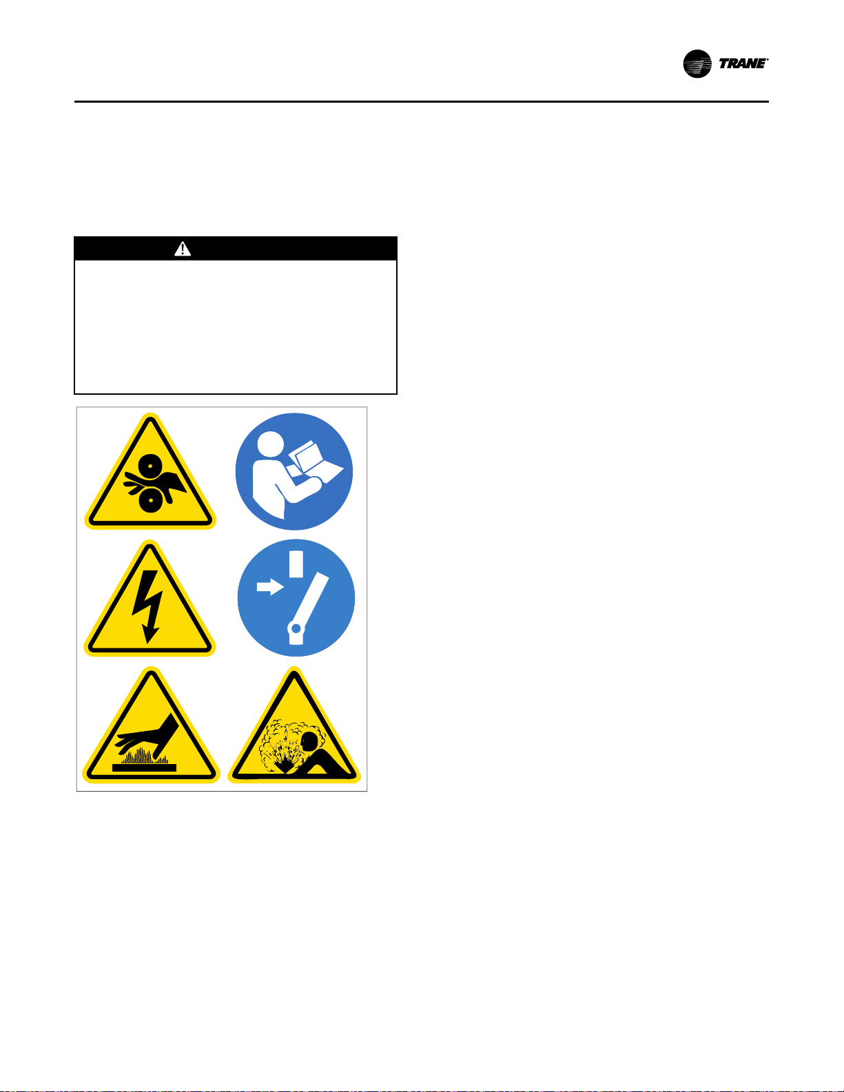
X39003892001A
SSyysstteemm CCoonnttrrooll CCiirrccuuiitt WWiirriinngg ((FFiieelldd WWiirriinngg))
Table 24. Unit control panel wiring 120 Vac (continued)
(b)
If the Condenser Water Flow Proving Input is a factory-installed ifm efector® flow-sensing device, the secondary (optional) field device for proof of flow
connects from 1X1-6 to 1K27-4 (binary input; normally open, closure with flow). Remove factory jumper when used.
(c)
Standard low-voltage circuits (less than 30 Vac) must be separated from 120 Vac or higher wiring.
Water Pump Interlock Circuits and Flow Switch Input
WWAARRNNIINNGG
HHaazzaarrddoouuss VVoollttaaggee!!
FFaaiilluurree ttoo ddiissccoonnnneecctt ppoowweerr bbeeffoorree sseerrvviicciinngg ccoouulldd
rreessuulltt iinn ddeeaatthh oorr sseerriioouuss iinnjjuurryy..
DDiissccoonnnneecctt aallll eelleeccttrriicc ppoowweerr,, iinncclluuddiinngg rreemmoottee
ddiissccoonnnneeccttss bbeeffoorree sseerrvviicciinngg.. FFoollllooww pprrooppeerr
lloocckkoouutt//ttaaggoouutt pprroocceedduurreess ttoo eennssuurree tthhee ppoowweerr
ccaann nnoott bbee iinnaaddvveerrtteennttllyy eenneerrggiizzeedd.. VVeerriiffyy tthhaatt nnoo
ppoowweerr iiss pprreesseenntt wwiitthh aa vvoollttmmeetteerr..
NNoottee:: Graphic labels (shown above) are used for CE
application only.
IImmppoorrttaanntt::
• Before servicing, disconnect all power
sources and allow at least 30 minutes
for capacitors to discharge.
• All electrical enclosures—unit or remote
—are IP2X.
NNoottee:: The circuits for the chilled water proof of flow
and the condenser water proof of flow do NOT
require external power. Refer to the wiring
diagrams that shipped with the chiller.
Chilled Water Pump
1. Wire the evaporator water pump contactor (5K42)
to a separate 120 volt single-phase power supply
with 14 AWG, 600V copper wire. For AWG/MCM
equivalents in mm
Requirements,” p. 53.
2. Connect circuit to 1K15-J2-6.
3. Use 1K15-J2-4 120 Vac output to allow the control
panel to control the evaporator water pump, or wire
the 5K1 contactor to operate remotely and
independently of the control panel.
2
, refer to the table in “Electrical
Chilled Water Proof of Flow
When this circuit is installed properly and the
evaporator pump is running and providing the required
minimum flow, this circuit will prove the evaporator
water flow for the chiller controls. Proof of evaporator
water flow is required before the start sequence will be
allowed to proceed and a loss of evaporator water flow
during chiller operation will result in a chiller shutdown.
Refer to as-built schematics on the inside of the control
panel for field wiring. This is a dry binary input;
normally-open, closure for flow. Apply no external
power.
1. With factory-installed ifm efector® flow-sensing
devices, a field-provided secondary flow-sensing
device is recommended with applications having
38°F (3.3°C) and below leaving evaporator water
temperatures. When a secondary flow-sensing
device is used, remove the factory jumper and
install its contacts between 1X1-5 to 1K26-4; this
places the secondary flow sensing device in series
with the ifm efector® flow-sensing device.
2. For field-provided primary proof of flow devices,
connect the primary proof of flow device between
terminals 1X1-5 to 1K16-J3-2. A secondary field
device is recommended with applications having
38°F (3.3°C) and below leaving evaporator water
temperatures, and must be field-wired in series
with the primary proof of flow device.
Condenser Water Pump
1. Wire the condenser water pump contactor (5K43) to
a separate 120-volt, single-phase power supply with
14 AWG, 600-volt copper wire. For AWG/MCM
equivalents in mm
Requirements,” p. 53.
2. Connect circuit to control panel terminals 1K15-J2-
3.
3. Use 1K15-J2-1 120 Vac output to allow the control
2
, refer to the table in “Electrical
CVHH-SVX001G-EN
73
Page 74

SSyysstteemm CCoonnttrrooll CCiirrccuuiitt WWiirriinngg ((FFiieelldd WWiirriinngg))
panel to control the condenser pump.
Condenser Water Proof of Flow
When this circuit is installed properly and the
condenser pump is running and providing the required
minimum condenser water flow, this circuit will prove
the condenser water flow for the chiller controls. Proof
of condenser water flow is also required for the start
sequence will be allowed to proceed and a loss of
condenser water flow during chiller operation will
result in a chiller shut-down.
Refer to as-built schematics on the inside of the control
panel for field wiring. This is a dry binary input;
normally-open, closure for flow. Apply no external
power.
1. With factory-installed ifm efector® flow-sensing
devices, a secondary field-provided flow-sensing
device is optional. When a secondary flow-sensing
device is used, remove the factory jumper, and
install its contacts between 1X1-5 to 1K27-4; this
places the secondary flow sensing device in series
with the ifm efector® flow-sensing device.
2. For field-provided primary proof of flow devices,
connect the primary proof of flow device between
terminals 1X1-6 to 1K16-J2-2. The secondary field
provided flow sensing device is optional; however,
when it is present, it must be field-wired in series
with the primary proof of flow device.
Sensor Circuits
All sensors are factory-installed except the optional
outdoor air temperature sensor (refer to the following
figure for sensor locations). This sensor is required for
the outdoor air temperature type of chilled water reset.
Use the following guidelines to locate and mount the
outdoor air temperature sensor. Mount the sensor
probe where needed; however, mount the sensor
module in the control panel.
74
CVHH-SVX001G-EN
Page 75

Figure 45. CVHH sensor locations
See Detail A
1
p
[
u
See Detail B
0
o
w
6
f
-
9
5
i
Detail A Detail B
=q
=q
ty
ty
er
er
er
er
ty
78
]\a
sd
234
SSyysstteemm CCoonnttrrooll CCiirrccuuiitt WWiirriinngg ((FFiieelldd WWiirriinngg))
1. Tracer® AdaptiView™ display module
2. Motor winding temperature 1
3. Motor winding temperature 2
4. Motor winding temperature 3
5. Oil pump discharge pressure transducer
6. Oil tank pressure transducer
7. Evaporator water differential pressure transducer
8. Condenser water differential pressure transducer
9. Compressor discharge refrigerant temperature sensor
10. Evaporator saturated refrigerant temperature sensor
11. Condenser saturated refrigerant temperature sensor
12. Second condenser entering water temperature sensor (used on HTRC)
13. Second condenser leaving water temperature sensor (used on HTRC)
14. Oil tank temperature sensor
15. Evaporator entering water temperature sensor
16. Evaporator leaving water temperature sensor
17. Condenser entering water temperature sensor
18. Condenser leaving water temperature sensor
19. Inboard bearing temperature sensor
20. Outboard bearing temperature sensor
CVHH-SVX001G-EN
75
Page 76

SSyysstteemm CCoonnttrrooll CCiirrccuuiitt WWiirriinngg ((FFiieelldd WWiirriinngg))
21. Oil cooling solenoid valve
22. Inlet guide vane first stage actuator
23. Inlet guide vane second stage actuator
24. Outboard bearing pad temperature sensor 1
25. Outboard bearing pad temperature sensor 2
26. Outboard bearing pad temperature sensor 3
27. Condenser high pressure cut out switch
28. Condenser refrigerant pressure transducer
29. Oil tank vent line valve
CWR—Outdoor Option
The outdoor temperature sensor is similar to the unitmounted temperature sensors in that it consists of the
sensor probe and the module. A four-wire interprocessor communication (IPC) bus is connected to the
module for 24 Vdc power and the communications link.
Trane recommends mounting the sensor module
within the control panel and the sensor two wire leads
be extended and routed to the outdoor temperature
sensor probe sensing location. This ensures the fourwire inter-processor control (IPC) bus protection and
provides access to the module for configuration at
start-up.
The sensor probe lead wire between the sensor probe
and the module can be separated by cutting the twowire probe lead leaving equal lengths of wire on each
device: the sensor probe and the sensor module.
NNoottee:: This sensor and module are matched and must
remain together or inaccuracy may occur.
These wires can then be spliced with two 14 to 18 AWG
600V wires of sufficient length to reach the desired
outdoor location with a maximum length 1000 ft
(304.8 m). For AWG/MCM equivalents in mm
the table in “Electrical Requirements,” p. 53. The
module four-wire bus must be connected to the control
panel four-wire bus using the Trane-approved
connectors provided.
The sensor will be configured (given its identity and
become functional) at start-up when the Trane service
technician performs the start-up configuration. It will
NOT be operational until that time.
NNoottee:: If shielded cable is used to extend the sensor
leads, be sure to cover the shield wire with tape
at the junction box and ground it at the control
panel. If the added length is run in conduit, do
NOT run them in the same conduit with other
circuits carrying 30 or more volts.
IImmppoorrttaanntt:: Maintain at least 6 in. (15.24 cm) between
low-voltage (less than 30V) and high
voltage circuits. Failure to do so could
result in electrical noise that may distort the
signals carried by the low-voltage wiring,
including the IPC.
2
, refer to
Optional Control and Output Circuits
Install various optional wiring as required by the
owner’s specifications (refer to “System Control Circuit
Wiring (Field Wiring),” p. 72).
Optional Tracer Communication Interface
This control option allows the control panel to
exchange information—such as chiller status and
operating set points—with a Tracer® system.
NNoottee:: The circuit must be run in separate conduit to
prevent electrical noise interference.
Additional information about the Tracer®
communication interface option is published in the
Installation and Operation manual that ships with the
Tracer® communication interface
Starter Module Configuration
The starter module configuration settings will be
checked (and configured for remote starters) during
start-up commissioning.
NNoottee:: To configure starter modules and perform other
starter checks, it is recommended that the line
voltage three-phase power be turned off and
secured (locked out), and then that a separate
source control power (115 Vac) be utilized to
power up the control circuits.
Use the as-built starter schematic to ensure correct
fuse and terminals. Verify that the correct fuse is
removed and that the control circuit connections are
correct; then apply the 115 Vac separate source power
to service the controls.
Schematic Wiring Drawings
Please refer to the submittals and drawings that
shipped with the unit. Additional wiring drawings for
CenTraVac™ chillers are available from your local
Trane office.
76
CVHH-SVX001G-EN
Page 77

Operating Principles
Condenser
High Side Economizer
Low Side Economizer
Evaporator
Compressor
Third Stage
Compressor
Second Stage
Compressor
First Stage
6
5
7
4
8
3
1 2
Pressure
Enthalpy
P
4
P
3
P
1
P
2
General Requirements
Operation and maintenance information for CVHH
CenTraVac™ chillers are covered in this section. This
includes both 50 and 60 Hz centrifugal chillers
equipped with the Tracer® AdaptiView™ UC800
control system. This information pertains to all chiller
types unless differences exist, in which case the
sections are listed by chiller type as applicable and
described separately. By carefully reviewing this
information and following the instructions given, the
owner or operator can successfully operate and
maintain a CenTraVac™ chiller. If mechanical problems
do occur, however, contact a Trane service technician
to ensure proper diagnosis and repair of the unit.
IImmppoorrttaanntt:: Although CenTraVac
™
chillers can operate
through surge, it is NOT recommended to
operate them through repeated surges over
long durations. If repeated surges of long
durations occur, contact your Trane Service
Agency to resolve the issue.
Cooling Cycle
When in the cooling mode, liquid refrigerant is
distributed along the length of the evaporator and
sprayed through small holes in a distributor (i.e.,
running the entire length of the shell) to uniformly coat
each evaporator tube. Here, the liquid refrigerant
absorbs enough heat from the system water circulating
through the evaporator tubes to vaporize. The gaseous
refrigerant is then drawn through the eliminators
(which remove droplets of liquid refrigerant from the
gas) and the first-stage variable inlet guide vanes, and
into the first-stage impeller.
further cooling the liquid refrigerant. This flash gas is
then drawn directly from the first and second stages of
the economizer into the third- and second-stage
impellers of the compressor, respectively. All
remaining liquid refrigerant flows through another
orifice plate to the evaporator.
Figure 46. Pressure enthalpy curve, 3-stage
Figure 47. Refrigerant flow, 3-stage
CVHH 3-Stage Compressor
Compressed gas from the first-stage impeller flows
through the fixed, second-stage inlet vanes and into
the second-stage impeller. Here, the refrigerant gas is
again compressed, and then discharged through the
third-stage variable guide vanes and into the thirdstage impeller. After the gas is compressed a third
time, it is discharged into the condenser. Baffles within
the condenser shell distribute the compressed
refrigerant gas evenly across the condenser tube
bundle. Cooling tower water circulated through the
condenser tubes absorbs heat from the refrigerant,
causing it to condense. The liquid refrigerant then
passes through an orifice plate and into the
economizer.
The economizer reduces the energy requirements of
the refrigerant cycle by eliminating the need to pass all
gaseous refrigerant through three stages of
compression (refer to the following figure). Notice that
some of the liquid refrigerant flashes to a gas because
of the pressure drop created by the orifice plates, thus
CVHH-SVX001G-EN
CVHH 2-Stage Compressor
Compressed gas from the first-stage impeller is
discharged through the fixed, second-stage variable
guide vanes and into the second-stage impeller. Here,
the refrigerant gas is again compressed, and then
discharged into the condenser. Baffles within the
condenser shell distribute the compressed refrigerant
gas evenly across the condenser tube bundle. Cooling
tower water circulated through the condenser tubes
absorbs heat from the refrigerant, causing it to
condense. The liquid refrigerant then passes through
an orifice plate and into the economizer.
The economizer reduces the energy requirements of
the refrigerant cycle by eliminating the need to pass all
gaseous refrigerant through both stages of
77
Page 78

Condenser
Economizer
Evaporator
Compressor
Second Stage
Compressor
First Stage
6
5
4
3
1 2
Pressure
Enthalpy
P
3
P
1
P
2
OOppeerraattiinngg PPrriinncciipplleess
compression (refer to the following figure). Notice that
some of the liquid refrigerant flashes to a gas because
of the pressure drop created by the orifice plate, thus
further cooling the liquid refrigerant. This flash gas is
then drawn directly from the economizer into the
second-stage impellers of the compressor. All
remaining liquid refrigerant flows out of the
economizer, passing through another orifice plate and
into the evaporator.
Figure 48. Pressure enthalpy curve
Oil and Refrigerant Pump
Compressor Lubrication System
A schematic diagram of the compressor lubrication
system is illustrated in the following figure. Oil is
pumped from the oil tank (by a pump and motor
located within the tank) through an oil pressure
regulating valve designed to maintain a net oil
pressure of 20 to 24 psid (137.9 to 165.5 kPaD). It is then
filtered and sent to the braze plate heat exchanger oil
cooler located above the oil tank and on to the
compressor motor bearings. From the bearings, the oil
drains back to the oil tank.
Figure 49. Refrigerant flow, 2-stage
78
CVHH-SVX001G-EN
Page 79

Figure 50. Oil refrigerant pump
Compressor lubrication system
Motor cooling system
Oil reclaim system
1
-
2
3
4
5
6
8
9
=
e
o
q
r
t
u
w
y
0
i
p
7
OOppeerraattiinngg PPrriinncciipplleess
1. Motor coolant return to condenser, 2.125 in. (53.975 mm) OD
2. Oil tank vent line, 2.125 in. (53.975 mm) OD
3. Vent line actuated ball valve
4. Condenser
5. High pressure condenser gas to drive oil reclaim eductors, 0.375 in. (9.525 mm) OD
6. Oil return to tank
7. Oil tank
8. Oil cooler braze plate heat exchanger
9. Oil reclaim from evaporator (second eductor), 0.25 in. (6.35 mm) OD
10. Liquid refrigerant to pump, 1.625 in. (41.275 mm) OD
11. Economizer
12. Oil supply to bearings, 0.875 in. (22.225 mm) OD
13. Purge
14. Compressor
15. Liquid refrigerant motor coolant supply, 1.125 in. (28.575 mm) OD
16. Liquid refrigerant to economizer
17. Liquid refrigerant to evaporator
18. Evaporator
19. Oil reclaim from suction cover (first eductor), 0.25 in. (6.35 mm) OD
20. Motor coolant filter
21. Oil tank junction box enclosure
22. Oil pump motor terminal box
CVHH-SVX001G-EN
79
Page 80

X39003892001A
OOppeerraattiinngg PPrriinncciipplleess
CCAAUUTTIIOONN
HHoott SSuurrffaaccee!!
FFaaiilluurree ttoo ffoollllooww iinnssttrruuccttiioonnss bbeellooww ccoouulldd rreessuulltt iinn
mmooddeerraattee iinnjjuurryy..
SSuurrffaaccee tteemmppeerraattuurreess ccaann rreeaacchh 115500°°FF ((6666°°CC)).. TToo
aavvooiidd ppoossssiibbllee sskkiinn bbuurrnnss,, ssttaayy cclleeaarr ooff tthheessee
ssuurrffaacceess.. IIff ppoossssiibbllee,, aallllooww ssuurrffaacceess ttoo ccooooll bbeeffoorree
sseerrvviicciinngg.. IIff sseerrvviicciinngg iiss nneecceessssaarryy wwhhiillee ssuurrffaaccee
tteemmppeerraattuurreess aarree ssttiillll eelleevvaatteedd,, yyoouu MMUUSSTT ppuutt oonn
aallll PPeerrssoonnaall PPrrootteeccttiivvee EEqquuiippmmeenntt ((PPPPEE))..
WWAARRNNIINNGG
HHaazzaarrddoouuss VVoollttaaggee iinn OOiill TTaannkk
JJuunnccttiioonn BBooxx EEnncclloossuurree aanndd OOiill PPuummpp
MMoottoorr TTeerrmmiinnaall BBooxx!!
FFaaiilluurree ttoo ddiissccoonnnneecctt mmaaiinn ppoowweerr aanndd//oorr aauuxxiilliiaarryy
ccoonnttrrooll ppoowweerr bbeeffoorree ooppeenniinngg ooiill ttaannkk jjuunnccttiioonn bbooxx
eenncclloossuurree oorr aannyy ootthheerr jjuunnccttiioonn bbooxx//tteerrmmiinnaall bbooxx//
ppaanneell oonn tthhee CCVVHHHH aanndd CCDDHHHH cchhiilllleerr ccaann rreessuulltt iinn
ddeeaatthh oorr sseerriioouuss iinnjjuurryy..
DDiissccoonnnneecctt aallll ppoowweerr aanndd aappppllyy lloocckkoouutt//ttaaggoouutt
ddeevviicceess.. FFoollllooww aallll ccoommppaannyy pprroocceedduurreess ffoorr
lloocckkoouutt//ttaaggoouutt.. UUnniitt mmuusstt bbee tteesstteedd ttoo eennssuurree aa
zzeerroo eenneerrggyy ssttaattee aanndd eeqquuiippmmeenntt mmuusstt bbee ppuutt iinn aann
eelleeccttrriiccaallllyy ssaaffee wwoorrkk ccoonnddiittiioonn pprriioorr ttoo
mmaaiinntteennaannccee.. HHaazzaarrddoouuss vvoollttaaggee uupp ttoo 660000 VVaacc iiss
pprreesseenntt iinn tthhee ooiill ttaannkk jjuunnccttiioonn bbooxx eenncclloossuurree aanndd
ooiill ppuummpp mmoottoorr tteerrmmiinnaall bbooxx..
NNoottee:: Graphic labels (shown above) are used for CE
application only.
IImmppoorrttaanntt::
• Before servicing, disconnect all power
sources and allow at least 30 minutes
for capacitors to discharge.
• All electrical enclosures—unit or remote
—are IP2X.
To ensure proper lubrication and prevent refrigerant
from condensing in the oil tank, two 750-watt heaters
are in wells in the oil tank and are used to heat the oil
while the unit is off. With the default settings, the oil
heaters are de-energized when the unit starts. The
heaters energize as needed to maintain 128°F to 133°F
(53.3°C to 56.1°C) when the chiller is not running.
When the chiller is operating, the temperature of the oil
tank is typically 100°F to 140°F (37.8°C to 60.0°C). The
oil return lines are routed into a separation chamber in
the oil tank. Gas flow exits out the top of the oil tank
and is vented to the evaporator.
A dual eductor system, using high pressure condenser
gas, reclaims oil from the suction cover and the
evaporator. The suction cover eductor is discharged
into the evaporator, and the evaporator eductor is
discharged into the oil tank. The evaporator eductor
line has a shut-off valve mounted on the evaporator.
The position of the shut-off valve will be set at two
turns open during commissioning but may be adjusted
later by a qualified technician as necessary for oil
return. A normal operating setting for the valve may
range from full closed to full open.
80
CVHH-SVX001G-EN
Page 81

OOppeerraattiinngg PPrriinncciipplleess
Oil supply to both the thrust bearing and journal
bearings is cooled when the oil tank temperature
reaches 140°F (60.0°C). The supply oil and liquid
refrigerant are pumped to a brazed plate heat
exchanger. The unit controller monitors oil tank
temperature and opens a solenoid valve to allow liquid
refrigerant to flow into the heat exchanger.
Motor Cooling System
Compressor motors are cooled with liquid refrigerant
(refer to the figure in “Compressor Lubrication
System,” p. 78). The refrigerant pump is located on the
front of the oil tank (motor inside the oil tank). The
refrigerant pump inlet is connected to the well at the
bottom of the condenser. The well design ensures
preferential supply of liquid refrigerant to the
refrigerant pump before refrigerant is supplied to the
economizer. Refrigerant is delivered to the motor via
the pump. An in-line filter is installed (replace the inline filter only with major service). Motor refrigerant
drain lines are routed to the condenser.
Tracer AdaptiView Display
Information is tailored to operators, service
technicians, and owners.
When operating a chiller, there is specific information
you need on a day-to-day basis—setpoints, limits,
diagnostic information, and reports.
Day-to-day operational information is presented at the
display. Logically organized groups of information—
chiller modes of operation, active diagnostics, settings,
and reports put information conveniently at your
fingertips. For more information, refer to Tracer
AdaptiView Display for Water-Cooled CenTraVac
Chillers Operations Guide (CTV-SVU01*-EN).
RuptureGuard
Operation
The rupture disk monitors the pressure inside the
chiller. If the pressure exceeds the disk’s burst setting,
the disk ruptures, allowing the chiller pressure to enter
the valve holder compartment upstream of the relief
valve. If the pressure is above the pressure setting of
the relief valve, the valve will open, allowing only the
amount of refrigerant to escape to keep the pressure
within safe operating limits.
The excess flow valve maintains the downstream side
of the rupture disk at atmospheric pressure to assure
proper operating conditions for the disk. When the disk
bursts, the rapid pressure increase causes the excess
flow valve to seal and the valve holder area becomes
pressurized.
A disk rupture will be indicated by a pressure reading
on the gauge and the pressure switch contacts will
close. The pressure switch is an optional accessory and
does not wire to the control panel. The pressure switch
can be connected to a customer-supplied building
automation system (BAS).
EarthWise Purge
General Information
Centrifugal chillers that use low-pressure refrigerants,
such as R-1233zd, operate with areas of the chiller at
less than atmospheric pressure. Non-condensables in
the air, such as water and nitrogen vapor, may leak into
these low-pressure areas and accumulate in the
condenser. If these non-condensables are not
removed, the condenser loses its ability to condense
refrigerant efficiently and the pressure of the
condenser increases. Increased condenser pressure
lowers the chiller’s efficiency and capacity.
A purge system is required on low-pressure centrifugal
chillers. It is a device that is externally mounted on the
chiller. Its purpose is to remove non-condensable
materials that have leaked into the machine.
NNoottee:: For convenience, the term “air” is often used in
describing non-condensables removed by the
purge system, although any other noncondensable materials that may exist in the
chiller are also removed by the purge system.
How a Purge System Works
From a functional standpoint, the purge system can be
divided into subsystems of components. This section
identifies and describes the function of these
subsystems.
Refrigeration Circuit Subsystem
The purge evaporator of the refrigeration circuit is
located in the purge tank. The purge tank is connected
to the chiller condenser by supply and return lines
through which chiller refrigerant can freely flow.
The purge evaporator coil presents a cold condensing
surface to the chiller refrigerant entering the purge
tank. When the purge refrigeration system is running,
refrigerant from the chiller condenser is attracted to the
cold surface of the purge evaporator. When the
gaseous refrigerant contacts the surface of the purge
evaporator coil, it condenses into a liquid, leaving a
partial vacuum behind. More refrigerant vapor from the
chiller condenser migrates to the purge tank to fill the
vacuum.
The liquid refrigerant that has condensed in the purge
tank returns to the chiller condenser through the liquid
return line. The return line includes a filter-drier and a
moisture-indicating sight glass.
The condensing unit is air-cooled and is operable
whether the chiller is running or not. No additional
cooling source is required.
CVHH-SVX001G-EN
81
Page 82

8
7
6
5
4
3
2
1
-
=
q
w
0
9
OOppeerraattiinngg PPrriinncciipplleess
1. Purge tank
2. Condensing unit (includes compressor, condenser coil, and fan)
3. Pressure-relief device (fusible plug)
4. Pump-out solenoid valve
5. Automatic expansion valve
6. Carbon tank
7. Carbon tank temperature sensor
8. Carbon tank heater
9. Exhaust solenoid valve
10. Pump-out compressor
11. Float switch
12. Compressor suction temperature sensor
13. Chiller refrigerant return line
14. Filter-drier canister
82
CVHH-SVX001G-EN
Page 83

-
=
0
9
8
7
6
5
4
2
1
OOppeerraattiinngg PPrriinncciipplleess
1. Regeneration solenoid valve
2. Pressure-relief valve
3. Exhaust solenoid valve
4. Pump-out compressor
5. Carbon tank heater
6. Automatic expansion valve
7. Pump-out solenoid valve
8. Pressure-relief device (fusible plug)
9. Carbon tank
10. Purge tank
11. Condensing unit
12. Chiller refrigerant supply line
Purge Tank Subsystem
Any non-condensables that have accumulated from the
refrigerant vapor are left behind to collect in the purge
tank. As the quantity of non-condensables increases,
the heat transfer efficiency of the purge evaporator coil
is reduced, causing the purge compressor suction
temperature to decrease.
A float switch, mounted in the bottom of the purge
tank, indicates if there is excessive accumulation of
liquid refrigerant in the tank. A liquid level sensor,
which resides in the purge control panel, monitors the
status of the float switch.
If the normally closed float switch is open for more
than 20 minutes, the purge controls will turn off the
CVHH-SVX001G-EN
83
Page 84

OOppeerraattiinngg PPrriinncciipplleess
refrigeration system and generate a non-latching
diagnostic—Purge Liquid Level Too High Warning. If
the float switch has re-closed after 20 minutes, the
purge controls will restart the refrigeration system.
If the float switch remains open for more than
20 minutes, or if the float switch/liquid level restart
cycle has occurred more than four times in four hours,
a latching diagnostic—Purge Liquid Level Too High
Continuously—will be generated. The purge system
will not restart until it is reset.
If a Purge Liquid Level Too High Continuously
diagnostic occurs, check the purge lines for any type of
restriction (trapped liquid, closed valves, etc.) and
ensure that the filter-drier on the liquid return line is in
good condition.
A UL-required pressure-relief device (fusible plug),
which protects against over-pressurization of the purge
tank, is mounted on the purge tank. The plug material
will fuse at 210°F (98.9°C), which equates to
approximately 132 psig (910.1 kPaG) for refrigerant R1233zd.
Pump-out Subsystem
When the purge control subsystem detects the
presence of non-condensables in the purge tank, the
pump-out solenoid and exhaust solenoid valves open,
and the pump-out compressor turns on. The valves and
the compressor cycle on and off as needed to achieve
an efficient and fast removal of non-condensables.
NNoottee:: A High Vacuum Pump option is available for
applications that require purge operation at low
condensing temperatures and pressures. This
option provides a two-stage pump-out
compressor. The High Vacuum Pump option
allows the purge system to operate to saturation
temperatures as low as 34°F (1.1°C). Typical
applications that may require the High Vacuum
Pump option include free-cooling installations,
series chiller installations, ice systems having
brine flowing through idle chillers, chillers
installed outdoors or in unconditioned spaces, or
any application that may cause very low
condenser water temperatures.
Carbon Tank and Regeneration Subsystem
The discharge from the pump-out compressor is piped
through the carbon tank. The special carbon in the tank
effectively scrubs and collects refrigerant molecules
from the non-condensable gas before the gas passes
through the exhaust solenoid valve to the chiller vent
line.
A 175 W resistive heater is mounted inside the carbon
tank and is used to periodically “regenerate” the
carbon bed and drive any collected refrigerant vapor
back into the chiller. A UL-required pressure-relief
valve, rated at 150 psig (1034.2 kPaG), is mounted on
the line leaving the carbon tank. The valve protects
against over-pressurization of the carbon tank.
A temperature sensor is installed through the top of the
carbon tank shell so that the controls can monitor the
carbon bed temperature. The temperature sensor
controls the regeneration cycle and protect against
overheating. If the limit temperature is reached, the
system shuts down and a Purge Carbon Regen
Temperature Limit Exceeded diagnostic is generated.
Sensors
The following sensors are used to enable control
communication between the Tracer® UC800 controller
and the EarthWise™ purge system. The sensors use
low-level intelligence devices (LLIDs) to communicate
with the Tracer® UC800 controller.
• CCoommpprreessssoorr ssuuccttiioonn tteemmppeerraattuurree sseennssoorr.. This
sensor is mounted on the purge condensing unit
suction line. The controller uses the value of this
temperature sensor to decide whether or not to
purge non-condensables from the purge tank.
When the temperature drops to a specified point,
the controller activates the pump-out cycle to
remove the accumulated non-condensables from
the purge tank. When enough non-condensables
have been removed and the purge compressor
suction temperature increases in response, the
controller terminates the pump-out cycle.
• SSaattuurraatteedd ccoonnddeennsseerr tteemmppeerraattuurree sseennssoorr.. This
sensor is mounted on the chiller. If the chiller is
running, the controller uses the value of this
temperature sensor to adjust the purge pump-out
initiate/terminate setpoints. It may be used to
prohibit pump-out if system conditions are too cool.
• SSaattuurraatteedd eevvaappoorraattoorr tteemmppeerraattuurree sseennssoorr.. This
sensor is mounted on the chiller. If the chiller is off,
the controller uses the value of this temperature
sensor to adjust the purge pump-out initiate/
terminate setpoints. It may be used to prohibit
pump-out if system conditions are too cool.
• CCaarrbboonn ttaannkk tteemmppeerraattuurree sseennssoorr.. This sensor is
mounted in the carbon tank of the purge system. It
provides feedback to the carbon regeneration
algorithm. The sensor and the controller function
much the same as a thermostat to control the
carbon tank heater.
• LLiiqquuiidd lleevveell sseennssoorr.. This sensor resides in the
purge control panel. It monitors the status of the
normally closed float switch, which is mounted in
the bottom of the purge tank. If an adequate
amount of liquid fails to drain from the purge tank,
the float switch and sensor detect the condition and
prevent further purge operation.
• CCoonnddeennssiinngg uunniitt LLLLIIDD.. This LLID resides in the
purge control panel. It uses a high-power relay to
control the operation of the purge condensing unit.
• QQuuaadd rreellaayy LLLLIIDD.. This LLID resides in the purge
control panel. It has four relay outputs that are used
to control the pump-out compressor, the carbon
84
CVHH-SVX001G-EN
Page 85

OOppeerraattiinngg PPrriinncciipplleess
tank heater, the regeneration solenoid valve, and an
alarm output.
• DDuuaall ttrriiaacc LLLLIIDD.. This LLID resides in the purge
control panel. It has two triac-type outputs that are
used to control the pump-out solenoid valve and
the exhaust solenoid valve. The purge system
draws its control power from the power supplies of
the chiller control panel.
CVHH-SVX001G-EN
85
Page 86

Start-up and Shut-down
Confirmed
Shutdown
Stopped
Stopped
Run Inhibit
Stopping
Preparing to Shut Down
Shutting Down
Running
Running
Running—Limit
Starting
Auto
Waiting to Start
Starting Compressor
Power
Up
Start
Command
Diagnostic
Res
e
t
Fast Restart or Satisfied Setpoint
Stop Command or Diagnostic
Stop Command
Diagnosti
c
Start
Confirmed
This section provides basic information on chiller
operation for common events.
Sequence of Operation
Adaptive control algorithms are used on CenTraVac™
chillers. This section illustrates common control
sequences.
Software Operation Overview Diagram
The following figure is a diagram of the five possible
software states. This diagram can be thought of as a
state chart, with the arrows and arrow text, depicting
the transitions between states:
• The text in the circles are the internal software
designations for each state.
Figure 51. Software operation overview
• The first line of text in the circles are the visible top
level operating modes that can be displayed in
Tracer® AdaptiView™.
• The shading of each software state circle
corresponds to the shading on the time lines that
show the state that the chiller is in.
There are five generic states that the software can be
in:
• Power Up
• Stopped
• Starting
• Running
• Stopping
In the following diagrams:
• The time line indicates the upper level operating
mode, as it would be viewed in the Tracer®
AdaptiView™.
• The shading color of the cylinder indicates the
software state.
86
• Text in parentheses indicates sub-mode text as
viewed in the Tracer® AdaptiView™.
• Text above the time line cylinder is used to illustrate
inputs to the UC800. This may include user input to
the Tracer® AdaptiView™ touch screen, control
inputs from sensors, or control inputs from a
generic BAS.
CVHH-SVX001G-EN
Page 87
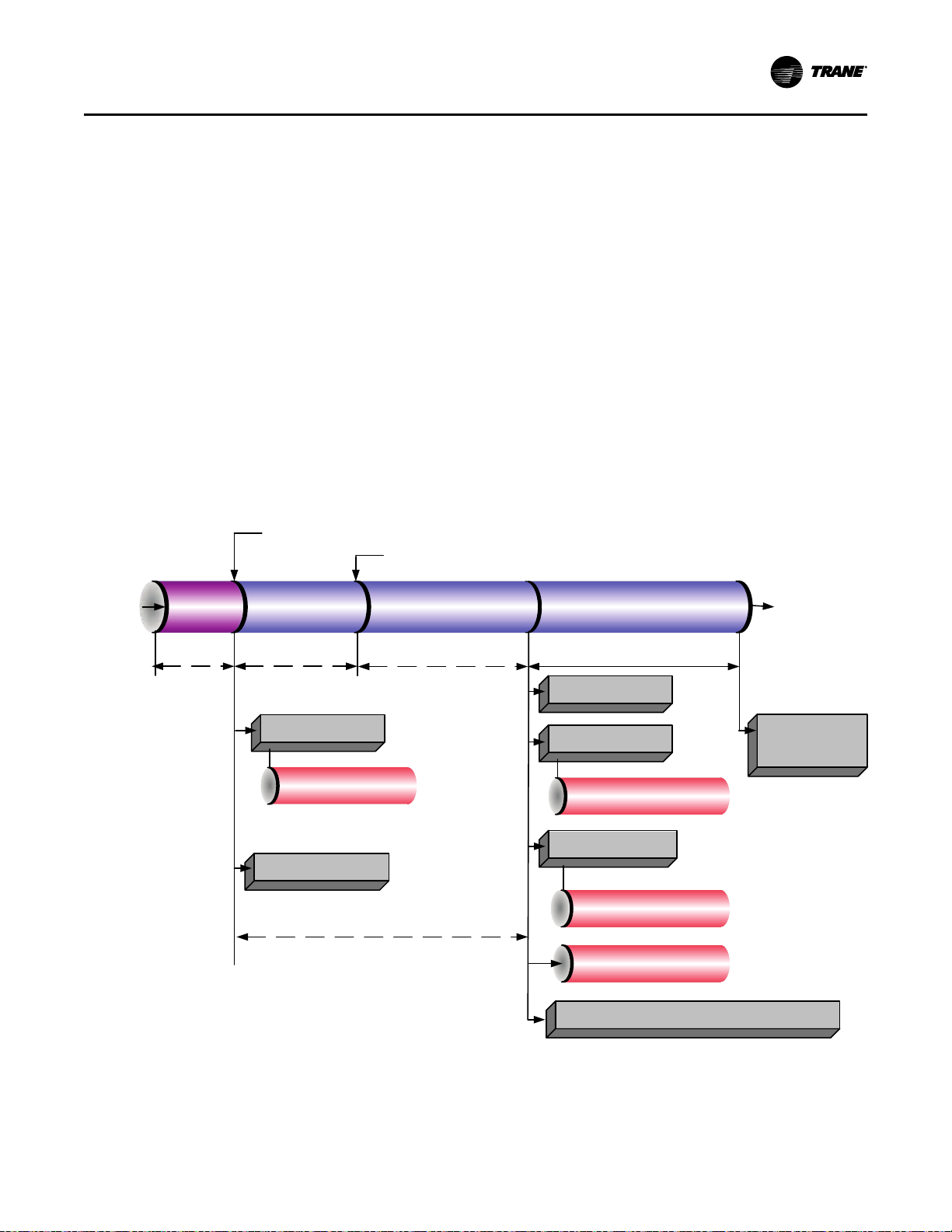
Power
Applied
to
Controls
Last Chiller Mode
Was Auto
Call for Cooling
Auto Waiting to Start
Waiting to Start
Starting
Compressor
UC800 Boot
Time
(30–50 sec)
Enforce Power
Up Start Delay
Timer (0–30 min)
Wait for Highest Motor Winding
Temp to Fall Below 165°F (73.9°C)
Wait for Oil Temp to Rise Above
Sat Evap + 30°F (16.7°C)
and 100°F (37.8°C)
Prelube (60 sec)
Begin Oil Vent Line
Valve low limit
venting
Overdrive IGV Closed
Energize Condenser
Water Pump Relay
Confirm Condenser Water Flow
Within 4 min 15 sec
(6 sec Filter)
Energize Oil Pump Relay
Confirm 12 psid (82.7 kPaD)
Oil Pressure
Within 3 min
Check for High Vacuum
Lockout
Initialize Oil Vent Line Valve to Minimum Open Position
Energize Evaporator
Water Pump Relay
Confirm Evaporator Water
Flow Within 4 min 15 sec
(6 sec Filter)
Open Oil Vent Line Valve
Enforce Stop to Start Timer Using Values From
Real Time Clock (5–200 sec, 30 is Default)
SSttaarrtt--uupp aanndd SShhuutt--ddoowwnn
• Boxes indicate control actions such as turning on
relays, or moving the inlet guide vanes.
• Smaller cylinders indicate diagnostic checks, text
indicates time-based functions, solid double arrows
indicate fixed timers, and dashed double arrows
indicate variable timers.
Start-up Sequence of Operation—Wyedelta
Logic circuits within the various modules will
determine the starting, running, and stopping
operation of the chiller. When operation of the chiller is
required, the chiller mode is set at “Auto.” Using
customer-supplied power, the chilled water pump relay
is energized and chilled water flow must be verified
within 4 minutes and 15 seconds, at the same time the
oil vent line valve is opened. The UC800 decides to
start the chiller based on the differential to start
setpoint. With the differential to start criteria met, the
UC800 then energizes condenser water pump relay
Figure 52. Sequence of operation: power up to starting
with customer-supplied power (refer to the following
figure).
Based on the Restart Inhibit function and the
Differential to Start setpoint, the oil and refrigerant
pump is energized, and the oil vent line valve is closed
to the minimum position. The oil pressure must be at
least 12 psid (82.7 kPaD) for 60 continuous seconds and
condenser water flow verified within 4 minutes and
15 seconds for the compressor start sequence to be
initiated. After the compressor starts, the oil vent line
valve begins to open; it can take between 15 and
30 minutes to fully open depending on the chiller
running conditions.
The compressor motor starts in the “Wye”
configuration and then, after the compressor motor has
accelerated and the maximum phase current has
dropped below 85 percent of the chiller nameplate RLA
for 1.5 seconds, the starter transitions to the “Delta”
configuration.
Now that the compressor motor is running in the
“Delta” configuration, the inlet guide vanes will
modulate, opening and closing to the chiller load
variation by operation of the stepper vane motor
actuator to satisfy chilled water setpoint. The chiller
CVHH-SVX001G-EN
continues to run in its appropriate mode of operation:
Normal, Softload, Limit Mode, and so on (refer to the
following figure [running]). If the oil tank temperature
rises above the oil cooler setpoint while the
compressor is running, the oil cooler solenoid valve
87
Page 88
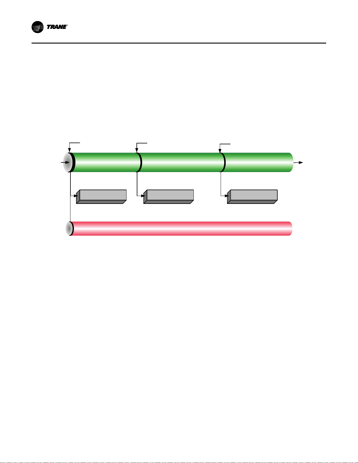
Starter
Status is
“Running”
Limit Mode
Exit
Limit Mode
Chiller
Is
Running
Starting
Compressor
Chiller Is Running
Chiller Is Running—Limit Chiller Is Running
Modulate IGV/AFD
for LWT control
Modulate IGV/AFD
for LWT control
Modulate IGV/AFD
for Limit control
Enforce All Running Mode Diagnostics
Note: If the Oil Tank Temperature rises above the Oil Cooler Control Setpoint whilte the
compressor is running, the Oil Cooler Solenoid Valve shall be energized to cool the unit.
SSttaarrtt--uupp aanndd SShhuutt--ddoowwnn
shall be energized to cool the oil.
If the chilled water temperature drops below the chilled
water setpoint by an amount set as the differential to
stop setpoint, a normal chiller stop sequence is
initiated as follows:
1. The inlet guide vanes are driven closed (up to
50 seconds).
2. After the inlet guide vanes are closed, the stop relay
and the condenser water pump relays open to turn
off. The oil and refrigerant pump motor will
Figure 53. Sequence of operation: running
continue to run for 3 minutes post-lube while the
compressor coasts to a stop. The oil vent line valve
will then open. The chilled water pump will
continue to run while the UC800 monitors leaving
chilled water temperature, preparing for the next
compressor motor start based on the differential to
start setpoint.
the following figure (satisfied setpoint) illustrates this
sequence.
88
CVHH-SVX001G-EN
Page 89

Figure 54. Sequence of operation: satisfied setpoint
Satisfied Setpoint
Preparing Shutdown
Shutting Down Shutting Down
Running
Auto
Close IGV (0–50 sec)
Postlube 3 min
De-Energize Oil Pump
Command IGV Closed
De-Energize
Compressor
Open Oil Vent Line Valve
Confirm No Oil Pressure*
5 min after oil pump is de-energized
Confirm No Compressor Currents
Within 0–30 sec
Hold position of Oil Vent Line Valve
De-Energize Condenser
Water Pump Relay
Enforce All Running Mode Diagnostics
*Note: No oil pressure is less than 3 psid (20.7 kPaD)
SSttaarrtt--uupp aanndd SShhuutt--ddoowwnn
If the STOP key is pressed on the operator interface, the
chiller will follow the same stop sequence as described
earlier except the chilled water pump relay will also
open and stop the chilled water pump after the chilled
water pump delay timer has timed out after
compressor shut down (refer to the following figure
[normal shut-down to stopped and run inhibit]).
If the immediate stop is initiated, a panic stop occurs
which follows the same stop sequence as pressing the
STOP key once, except the inlet guide vanes are not
sequence-closed and the compressor motor is
immediately turned off.
CVHH-SVX001G-EN
89
Page 90

Local Stop
Normal Latching Diagnostic
Normal Non-Latching Diagnostic
Tracer Stop
External Auto-Stop
IGV Closed
Preparing Shutdown Shutting Down
Shutting Down
Running
Stopped
Run Inhibit
Stopped
or
Run Inhibit
Evap Pump
Off Delay
and Postlube
Complete
Close IGV (0–50 sec) Postlube 3 min
Evap Pump Off Delay Time
(0–30 min)
Command IGV Closed
Enforce All Running Mode Diagnostics
De-Energize Condenser
Water Pump Relay
De-Energize
Compressor
Confirm No Compressor Currents
Within 8 sec
Hold position of Oil Vent Line Valve
Open Oil Vent Line Valve
De-Energize Oil Pump
Confirm No Oil Pressure*
5 min after oil pump
is de-energized
De-Energize Evaporator
Water Pump Relay
*Note: No oil pressure is less than 3 psid (20.7 kPaD)
SSttaarrtt--uupp aanndd SShhuutt--ddoowwnn
Figure 55. Sequence of operation: normal shut-down to stopped and run inhibit
Power Up Diagram
“Software Operation Overview Diagram,” p. 86
includes an illustration of Tracer® AdaptiView™ during
a power up of the UC800. This process takes from 30 to
50 seconds depending on the number of installed
options.
Ice Machine Control
The control panel provides a service level Enable or
Disable menu entry for the Ice Building feature when
the Ice Building option is installed. Ice Building can be
entered from Front Panel or, if hardware is specified,
the control panel will accept either an isolated contact
closure 1K9 Terminals J2-1 and J2-2 (Ground) or a
remote-communicated input (BAS) to initiate the ice
building mode where the unit runs fully loaded at all
times. Ice building will be terminated either by opening
the contact or based on entering evaporator fluid
temperature. The control panel will not permit the Ice
Building mode to be entered again until the unit is
switched to the non-ice building mode and back into
the ice building mode. It is not acceptable to reset the
chilled water setpoint low to achieve a fully loaded
compressor. When entering ice building, the
compressor will be loaded at its maximum rate and
when leaving ice building, the compressor will be
unloaded at its maximum rate. While loading and
unloading the compressor, all surge detection will be
ignored. While in the ice building mode, current limit
setpoints less than the maximum will be ignored. Ice
Building can be terminated by one of the following
means:
• Front panel disable
• Opening the external ice contacts/remotecommunicated input (BAS)
• Satisfying an evaporator entering fluid temperature
setpoint (default is 27°F [-2.8°C])
• Surging for seven minutes at full open inlet guide
vanes (IGV)
90
CVHH-SVX001G-EN
Page 91

Figure 56. Sequence of operation: ice building: running to ice building
Ice Making Command:
1. Front Panel
2. Tracer
3. External Input
Evap Leaving
Water Temp Rises
Above the Diff To
Stop
Ice Making
Command
Withdrawn
Running
Running
Running
(Ice Building)
Running (Ice to Normal
Transition)
Running
Ice to Normal Transition Timer
(0–10 min)
Head Relief Request Relay
Delay (1–60 min)
Head Relief Request Relay
Delay (1–60 min)
Open IGV at Max Rate/
Max AFD Frequency
Ignore Softloading and
Set CLS=100%
Energize Ice Building
Relay
Close IGV/Min AFD
Frequency
De-Energize Ice Building
Relay
Modulate IGV/AFD
for LWT control
De-Energize Head Relief
Request Relay
Energize Head Relief
Request Relay
Enforce All Limits and Running Mode Diagnostics
SSttaarrtt--uupp aanndd SShhuutt--ddoowwnn
CVHH-SVX001G-EN
91
Page 92

Ice Making Command:
1. Front Panel
2. Tracer
3. External Input
Evap Entering
Water Temp Falls
Below the Ice
Termination
Setpoint
Auto
Run Inhibit
(Ice Building
Complete)
Starting
Compressor
Running
(Ice Building)
Preparing to
Shut Down
Shutting
Down
Run
Inhibit
Open IGV at Max Rate/
Max AFD Frequency
Close IGV
(0–50 sec)
Postlube
(3 min)
Heat Relief Request Relay
Delay (1–60 min)
Ignore Evap Pump
Off Delay Time
for Ice Building
Close IGV/Min AFD
Frequency
De-Energize Oil Pump
Open Oil Vent Line Valve
Hold position of Oil Vent Line Valve
De-Energize
Condenser
Water Pump Relay
De-Energize Evaporator
Water Pump Relay
De-Energize
Compressor
Con
firm No Compressor Currents
Within 8
sec
Ignore Softloading and
Set CLS=100%
Energize Ice Building
Relay
Begin Oil Vent Line
Valve low limit venting
Enforce All Limits and Running Mode Diagnostics
De-Energize Ice
Building Relay
De-Energize Heat
Relief Request Relay
Energize Head Relief
Request Relay
SSttaarrtt--uupp aanndd SShhuutt--ddoowwnn
Figure 57. Sequence of operation: ice building: stopped to ice to ice building complete
Free Cooling Cycle
Based on the principle that refrigerant migrates to the
coldest area in the system, the free cooling option
adapts the basic chiller to function as a simple heat
exchanger. However, it does not provide control of the
leaving chilled water temperature.
If condenser water is available at a temperature lower
than the required leaving chilled water temperature,
the operator interface must remain in AUTO and the
operator starts the free cooling cycle by enabling the
Free Cooling mode in the Tracer® AdaptiView™
Feature Settings group of the operator interface, or by
means of a BAS request. The following components
must be factory- or field-installed to equip the unit for
free cooling operation:
• a refrigerant gas line, and electrically-actuated
shutoff valve, between the evaporator and
condenser, and
• a valved liquid return line, and electrically-actuated
shutoff valve, between the condenser sump and the
evaporator.
When the chiller is changed over to the free cooling
mode, the compressor will shut down if running and
the shutoff valves in the liquid and gas lines open; unit
control logic prevents the compressor from energizing
92
during free cooling. Since the temperature and
pressure of the refrigerant in the evaporator are higher
than in the condenser (i.e., because of the difference in
water temperature), the refrigerant in the evaporator
vaporizes and travels to the condenser, cooling tower
water causes the refrigerant to condense on the
condenser tubes, and flow (again, by gravity) back to
the evaporator.
This compulsory refrigerant cycle is sustained as long
as a temperature differential exists between condenser
and evaporator water. The actual cooling capacity
provided by the free cooling cycle is determined by the
difference between these temperatures which, in turn,
determines the rate of refrigerant flow between the
evaporator and condenser shells.
If the system load exceeds the available free cooling
capacity, the operator must manually initiate
changeover to the mechanical cooling mode by
disabling the free cooling mode of operation. The gas
and liquid line valves then close and compressor
operation begins (refer to the figure in “Start-up
Sequence of Operation—Wye-delta,” p. 87 [power up
to starting], beginning at Auto mode). Refrigerant gas
is drawn out of the evaporator by the compressor,
where it is then compressed and discharged to the
condenser.
CVHH-SVX001G-EN
Page 93

SSttaarrtt--uupp aanndd SShhuutt--ddoowwnn
Hot Water Control
Occasionally, CenTraVac™ chillers are selected to
provide heating as a primary mission. With hot water
temperature control, the chiller can be used as a
heating source or cooling source. This feature provides
greater application flexibility. In this case, the operator
selects a hot water temperature and the chiller capacity
is modulated to maintain the hot water setpoint.
Heating is the primary mission and cooling is a waste
product or is a secondary mission. This type of
operation requires an endless source of evaporator
load (heat), such as well or lake water. The chiller has
only one condenser.
NNoottee:: Hot Water Temperature Control mode does NOT
convert the chiller to a heat pump. Heat pump
refers to the capability to change from a coolingdriven application to a heating-driven application
by changing the refrigerant path on the chiller.
This is impractical for centrifugal chillers as it
would be much easier to switch over the water
side.
This is NOT heat recovery. Although this feature could
be used to recover heat in some form, a heat recovery
unit has a second heat exchanger on the condenser
side.
The Tracer® AdaptiView™ provides the Hot Water
Temperature Control mode as standard. The leaving
condenser water temperature is controlled to a hot
water setpoint between 80°F and 140°F (26.7°C and
60.0°C). The leaving evaporator water temperature is
left to drift to satisfy the heating load of the condenser.
In this application, the evaporator is normally piped
into a lake, well, or other source of constant
temperature water for the purpose of extracting heat.
In Hot Water Temperature Control mode, all the limit
modes and diagnostics operate as in normal cooling
with one exception: the leaving condenser water
temperature sensor is an MMR diagnostic when in Hot
Water Temperature Control mode. (It is an
informational warning in the Normal Cooling mode.)
In the Hot Water Temperature Control mode, the
differential-to-start and differential-to-stop setpoints
are used with respect to the hot water setpoint instead
of with the chilled water setpoint. The control panel
provides a separate entry at the Tracer® AdaptiView™
to set the hot water setpoint; Tracer® AdaptiView™ is
also able to set the hot water setpoint. In the Hot Water
mode, the external chilled water setpoint is the external
hot water setpoint; that is, a single analog input is
shared at the 1K6-J2-5 to 6 (ground).
An external binary input to select external Hot Water
Control mode is on the EXOP OPTIONAL module 1K8
terminals J2-3 to J2-4 (ground). Tracer® AdaptiView™
also has a binary input to select chilled water control or
hot water temperature control. There is no additional
leaving hot water temperature cutout; the HPC and
condenser limit provide for high temperature and
pressure protection.
In Hot Water Temperature Control, the softloading
pulldown rate limit operates as a softloading pullup
rate limit. The setpoint for setting the temperature rate
limit is the same setpoint for normal cooling as it is for
hot water temperature control. The hot water
temperature control feature is not designed to run with
HGBP, AFD, free cooling, or ice-building.
The factory set PID tuning values for the leaving water
temperature control are the same settings for both
normal cooling and hot water temperature control.
Control Panel Devices and UnitMounted Devices
Unit Control Panel
Safety and operating controls are housed in the unit
control panel, the starter panel, and the purge control
panel. The control panel operator interface and UC800
is called Tracer® AdaptiView™ and is located on an
adjustable arm connected to the base of the control
panel. For more information about operating Tracer®
AdaptiView™, refer to Tracer AdaptiView Display for
Water-Cooled CenTraVac Chillers Operations Guide
(CTV-SVU01*-EN).
The control panel houses several other controls
modules called panel-mounted Low Level Intelligent
Devices (LLIDs), power supply, terminal block, fuse,
circuit breakers, and transformer. The inter-processor
communication (IPC) bus allows the communications
between LLIDs and the UC800. Unit-mounted devices
are called frame-mounted LLIDs and can be
temperature sensors or pressure transducers. These
and other functional switches provide analog and
binary inputs to the control system.
User-Defined Language Support
Tracer® AdaptiView™ is capable of displaying English
text or any of 26 other languages. Switching languages
is simply accomplished from a Language Settings
menu. The following languages are available:
• Arabic (Gulf Regions)
• Chinese—China
• Chinese—Taiwan
• Czech
• Dutch
• English
• French
• French (Canada)
• German
• Greek
• Hebrew
• Hungarian
• Indonesian
CVHH-SVX001G-EN
93
Page 94

SSttaarrtt--uupp aanndd SShhuutt--ddoowwnn
• Italian
• Japanese
• Korean
• Norwegian
• Polish
• Portuguese (Portugal)
• Portuguese (Brazil)
• Russian
• Romanian
• Spanish (Europe)
• Spanish (Latin America)
• Swedish
• Thai
Unit Start-up and Shut-down Procedures
WWAARRNNIINNGG
LLiivvee EElleeccttrriiccaall CCoommppoonneennttss!!
FFaaiilluurree ttoo ffoollllooww aallll eelleeccttrriiccaall ssaaffeettyy pprreeccaauuttiioonnss
wwhheenn eexxppoosseedd ttoo lliivvee eelleeccttrriiccaall ccoommppoonneennttss ccoouulldd
rreessuulltt iinn ddeeaatthh oorr sseerriioouuss iinnjjuurryy..
WWhheenn iitt iiss nneecceessssaarryy ttoo wwoorrkk wwiitthh lliivvee eelleeccttrriiccaall
ccoommppoonneennttss,, hhaavvee aa qquuaalliiffiieedd lliicceennsseedd eelleeccttrriicciiaann
oorr ootthheerr iinnddiivviidduuaall wwhhoo hhaass bbeeeenn pprrooppeerrllyy ttrraaiinneedd
iinn hhaannddlliinngg lliivvee eelleeccttrriiccaall ccoommppoonneennttss ppeerrffoorrmm
tthheessee ttaasskkss..
WWAARRNNIINNGG
TTooxxiicc HHaazzaarrddss!!
AA ssiiggnniiffiiccaanntt rreelleeaassee ooff rreeffrriiggeerraanntt iinnttoo aa ccoonnffiinneedd
ssppaaccee dduuee ttoo aa rruuppttuurree ddiisskk ffaaiilluurree ccoouulldd ddiissppllaaccee
aavvaaiillaabbllee ooxxyyggeenn ttoo bbrreeaatthhee aanndd ccaauussee ppoossssiibbllee
aasspphhyyxxiiaattiioonn.. FFaaiilluurree ttoo ffoollllooww iinnssttrruuccttiioonnss bbeellooww
ccoouulldd rreessuulltt iinn ddeeaatthh oorr sseerriioouuss iinnjjuurryy..
SShhoouulldd aa rruuppttuurree ddiisskk ffaaiill,, eevvaaccuuaattee tthhee aarreeaa
iimmmmeeddiiaatteellyy aanndd ccoonnttaacctt tthhee aapppprroopprriiaattee rreessccuuee oorr
rreessppoonnssee aauutthhoorriittyy..
WWhhiillee tthhee uunniitt iiss ooffff,, ddoo nnoott aallllooww tthhee cchhiilllleerr ttoo
eexxcceeeedd 111100°°FF ((4433..33°°CC)) ffoorr mmooddeellss CCDDHHFF,, CCDDHHGG,,
CCVVHHEE,, CCVVHHFF,, CCVVHHGG,, CCVVHHLL,, CCVVHHMM,, aanndd CCVVHHSS oorr
aabboovvee 113300°°FF ((5544..44°°CC)) ffoorr mmooddeellss CCDDHHHH aanndd CCVVHHHH..
FFaaiilluurree ttoo pprreevveenntt hhiigghh cchhiilllleerr tteemmppeerraattuurree wwiillll
ccaauussee tthhee iinnssiiddee pprreessssuurree ttoo rriissee::
•• DDoo nnoott rruunn eevvaappoorraattoorr wwaatteerr ppuummpp lloonnggeerr tthhaann
3300 mmiinnuutteess aafftteerr tthhee cchhiilllleerr iiss sshhuutt ddoowwnn..
•• EEnnssuurree tthhaatt tthhee eevvaappoorraattoorr iiss iissoollaatteedd ffrroomm tthhee
hhoott wwaatteerr lloooopp bbeeffoorree cchhaannggeeoovveerr ttoo hheeaattiinngg
mmooddee..
TThhee rruuppttuurree ddiisskk iiss ddeessiiggnneedd ttoo rreelliieevvee aanndd
ddiisscchhaarrggee tthhee rreeffrriiggeerraanntt ffrroomm tthhee uunniitt iiff tthhee
pprreessssuurree iinn tthhee eevvaappoorraattoorr eexxcceeeeddss 1155 ppssiigg ((110033..44
kkPPaaGG)) ffoorr mmooddeellss CCDDHHFF,, CCDDHHGG,, CCVVHHEE,, CCVVHHFF,,
CCVVHHGG,, CCVVHHLL,, CCVVHHMM,, aanndd CCVVHHSS oorr 5500 ppssiigg ((334444..77
kkPPaaGG)) ffoorr mmooddeellss CCDDHHHH aanndd CCVVHHHH..
94
CVHH-SVX001G-EN
Page 95

X39003892001A
NNoottee:: Graphic labels (shown above) are used for CE
application only.
IImmppoorrttaanntt::
• Before servicing, disconnect all power
sources and allow at least 30 minutes
for capacitors to discharge.
• All electrical enclosures—unit or remote
—are IP2X.
Daily Unit Start-up
1. Verify the chilled water pump and condenser water
pump starter are in ON or AUTO.
2. Verify the cooling tower is in ON or AUTO.
3. Check the oil tank oil level; the level must be visible
in or above the lower sight glass. Also, check the oil
tank temperature; normal oil tank temperature
before start-up is 128°F to 133°F (53.3°C to 56.1°C).
4. Check the chilled water setpoint and readjust it, if
necessary, in the Chiller Settings menu.
5. If necessary, readjust the current limit setpoint in
the Chiller Setpoints menu.
6. Press AUTO.
The control panel also checks compressor motor
winding temperature and a start is initiated after a
minimum restart inhibit time if the winding
temperature is less than 265°F (129.4°C). The chilled
water pump relay is energized and evaporator water
flow is proven. Next, the control panel checks the
leaving evaporator water temperature and compares it
SSttaarrtt--uupp aanndd SShhuutt--ddoowwnn
to the chilled water setpoint. If the difference between
these values is less than the start differential setpoint,
cooling is not needed.
If the control panel determines that the difference
between the evaporator leaving water temperature and
chilled water setpoint exceeds the start differential
setpoint, the unit enters the initiate Start Mode and the
oil and refrigerant pump and the condenser water
pump are started. If flow is not initially established
within 4 minutes 15 seconds of the condenser pump
relay energization, an automatically resetting
diagnostic “Condenser Water Flow Overdue” shall be
generated, which terminates the prestart mode and deenergizes the condenser water pump relay. This
diagnostic is automatically reset if flow is established
at any later time.
NNoottee:: This diagnostic does NOT automatically reset if
Tracer
®
AdaptiView™is in control of the
condenser pump through its condenser pump
relay, since it is commanded off at the time of
the diagnostic. It may reset and allow normal
chiller operation if the pump was controlled from
some external source.
If the compressor motor starts and accelerates
successfully, Running appears on the display. If the
purge is set to AUTO, the purge will start running and
will run as long as the chiller is running.
NNoottee:: If a manual reset diagnostic condition is detected
during start-up, unit operation will be locked out
and a manual reset is required before the startup sequence can begin again. If the fault
condition has not cleared, the control panel will
not permit restart.
When the cooling requirement is satisfied, the control
panel originates a Shutting down signal. The inlet
guide vanes are driven closed for 50 seconds, the
compressor stops, and the unit enters a 3-minute postlube period. The evaporator pump may continue to run
for the amount of time set using Tracer® AdaptiView™.
After the post-lube cycle is done, the unit returns to
auto mode.
Seasonal Unit Start-up
1. Close all drain valves, and reinstall the drain plugs
in the evaporator and condenser headers.
2. Service the auxiliary equipment according to the
start-up and maintenance instructions provided by
the respective equipment manufacturers.
3. Fill and vent the cooling tower, if used, as well as
the condenser and piping. At this point, all air must
be removed from the system (including each pass).
Then, close the vents in the condenser waterboxes.
4. Open all of the valves in the evaporator chilled
water circuit.
5. If the evaporator was previously drained, fill and
vent the evaporator and chilled water circuit. After
CVHH-SVX001G-EN
95
Page 96

SSttaarrtt--uupp aanndd SShhuutt--ddoowwnn
all air is removed from the system (including each
pass), close the vent valves in the evaporator
waterboxes.
6. Lubricate the external vane control linkage as
needed.
7. Check the adjustment and operation of each safety
and operating control.
8. Close all disconnect switches.
9. Perform instructions listed in “Daily Unit Start-
up,” p. 95.
Daily Unit Shut-down
NNoottee:: Also refer to the figure (satisfied setpoint) in
“Start-up Sequence of Operation—Wye-delta,” p.
87.
1. Press STOP.
2. After compressor and water pumps shut down, the
operator may turn Pump Contactors to OFF or open
pump disconnects.
Seasonal Unit Shut-down
IImmppoorrttaanntt:: Control power disconnect switch must
remain closed to allow oil sump heater
operation. Failure to do this will allow
refrigerant to condense in the oil pump.
1. Open all disconnect switches except the control
power disconnect switch.
2. Drain the condenser piping and cooling tower, if
used. Rinse with clean water.
3. Remove the drain and vent plugs from the
condenser headers to drain the condenser. Air-dry
bundle of residual water.
4. Once the unit is secured for the season, the
maintenance procedures described in “Normal
Operation,” p. 106 (tables for recommended
maintenance of standard and optional features)
should be performed by qualified Trane service
technicians.
NNoottee:: During extended shut-down periods, be sure to
operate the purge unit for a two-hour period
every two weeks. This will prevent the
accumulation of air and non-condensables in the
machine. To start the purge, change the purge
mode to ON in the unit control “Settings Purge”
menu. Remember to turn the purge mode to
“Adaptive” after the two-hour run time.
EarthWise Purge
Sequence of Operations
A Tracer® UC800 controller that is configured to
control a purge system uses the operational sequences
described in this section.
Purge Operating Modes
Purge operating mode options are as follows:
• SSttoopp.. The purge condensing unit does not run in
this mode.
• OOnn.. The purge condensing unit runs continuously
in this mode, regardless of the chiller’s operational
status.
• AAuuttoo.. The purge condensing unit runs in this mode
if the main compressor of the chiller is operating.
• AAddaappttiivvee.. The purge condensing unit operation
depends on past purge activity.
Adaptive Mode
The objectives of operating the unit in the Adaptive
mode are to:
• Enable purge system operation.
• Enable the refrigeration circuit to effectively
accumulate non-condensables whether or not the
chiller is running.
• Provide information to an operator regarding
whether leakage is on the high-pressure or lowpressure side of the chiller.
• Decrease energy usage by running the purge
refrigeration circuit only when needed to remove
non-condensables, rather than running it
continuously.
The Adaptive mode requires historical operating data
so that the controller can make optimal decisions
regarding how to run the purge refrigeration circuit in
the future. On initial start-up of a chiller that is in
Adaptive mode, the purge refrigeration circuit runs
continuously for 168 hours (7 days). The chiller
compressor may or may not be running during this
period.
Following the initial data collection period, the
Adaptive mode customizes the purge refrigeration
circuit operation during two distinct chiller operating
conditions:
• Chiller compressor On
• Chiller compressor Off
Adaptive Mode Process—Chiller Compressor On
The following figure illustrates the process described in
this subsection.
When the chiller compressor starts, the purge
refrigeration circuit starts. The purge refrigeration
circuit continues to run until 60 consecutive minutes of
running occur without any pump-out of noncondensables. The Pumpout Time is the greater of the
following two values that the controller has been
tracking:
• The pump-out time with the chiller On, over the last
24 hours
96
CVHH-SVX001G-EN
Page 97
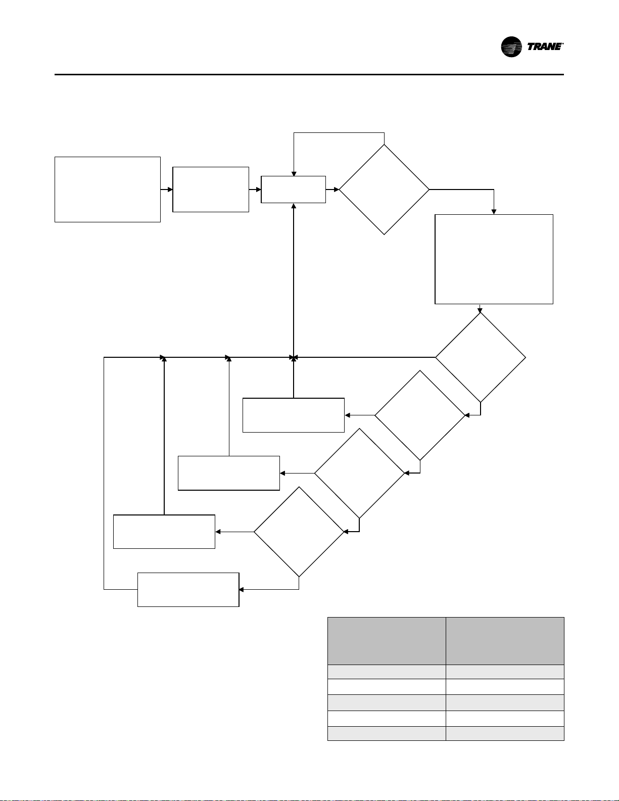
• The average daily pump-out time with the chiller
First chiller power-up.
Purge operates
continuously for 168
hours to collect data.
Chiller On or Off.
Chiller and
purge start.
Purge runs.
No
Has purge
run 60
minutes
without any
pump-out?
Yes
The purge control reviews
the historical data and
determines the Pumpout
Time with the chiller On
(Pumpout Time from last
24 hours daily average
over last 7 days, whichever
is greater.
Is Pumpout
Time greater
than 8
minutes?
No
Yes
Is Pumpout
Time greater
than 5
minutes?
No
Yes
No
Yes
No
Yes
Is Pumpout
Time greater
than 3
minutes?
Is Pumpout
Time greater
than 1
minute?
Turn purge unit Off for
4 hours, then restart.
Turn purge unit Off for
3 hours, then restart.
Turn purge unit Off for
2 hours, then restart.
Turn purge unit Off for
1 hour, then restart.
On, over the last 7 days
Figure 58. Adaptive chiller ON flow chart
SSttaarrtt--uupp aanndd SShhuutt--ddoowwnn
The purge then shuts down for a corresponding period
of time, as shown in the following table:
Pumpout Time with chiller
On (over the last 24 hours
or daily average over the
last 7 days, whichever is
greater)
Pumpout Time ≤ 1 minute
1 minute < Pumpout Time ≤ 3
minutes
3 minutes < Pumpout Time ≤ 5
minutes
5 minutes < Pumpout Time ≤ 8
minutes
Pumpout Time > 8 minutes No Off cycle
Purge Off cycle duration
4 hours
3 hours
2 hours
1 hour
CVHH-SVX001G-EN
97
Page 98

First chiller power-
up. Purge operates
continuously for 168
hours to collect data.
Chiller On or Off.
Chiller Off. Purge Off.
The purge control reviews the
historical pump-out data for
“chiller On” and “chiller Off” and
determines the Pumpout Time
(from the last 24 hours, or the
daily average over the last 7 days,
whichever is greater).
Turn purge Off.
Is purge
running for
60 minutes
without
purging?
Yes
No
Hold purge Off
for 6 hours.
No
No
No
Yes
Yes
Yes
Is Pumpout
Time less than
5 minutes?
Is Pumpout
Time less than
3 minutes?
Is Pumpout
Time less than
1 minute?
Hold purge Off
for 3 days.
Hold purge Off
for 2 days.
Hold purge Off
for 1 day.
Run purge.
SSttaarrtt--uupp aanndd SShhuutt--ddoowwnn
During the purge refrigeration circuit Off cycle, the time
remaining is displayed as Time Until Next Purge Run in
the Log Sheet that you can view from the Tracer®
AdaptiView™ display.
If the compressor is turned Off during the purge
refrigeration circuit Off cycle, the purge transfers to
Adaptive Mode Procedure—Chiller Compressor
Off.“Adaptive Mode Procedure—Chiller Compressor
Off,” p. 98 includes an illustration of this process.
Adaptive Mode Procedure—Chiller Compressor
Off
Refer to the following figure for an illustration of the
process described in this subsection.
Figure 59. Adaptive chiller OFF flow chart
If the chiller compressor is turned Off, the purge
refrigeration circuit Off cycle is determined by the
purge control. The purge Off-cycle duration is
determined by the pump-out time, which is the greater
of the following two values:
• Daily Pumpout—24 hours (the pump-out time over
the last 24 hours whether the chiller is On or Off)
• Average Daily Pumpout—7 days (the pump-out
time with the chiller On over the last 7 days)
NNoottee:: These two values can be seen on the Tracer
AdaptiView™display.
®
The purge will be shut down for a corresponding
period of time, as shown in the following table:
98
CVHH-SVX001G-EN
Page 99

SSttaarrtt--uupp aanndd SShhuutt--ddoowwnn
Pumpout Time with chiller On or Off
(over the last 24 hours or daily average
over the last 7 days, whichever is
greater)
Pumpout Time ≤ 1 minute 3 days
1 minute < Pumpout Time ≤ 3 minutes 2 days
3 minutes < Pumpout Time ≤ 5 minutes 1 day
Pumpout Time > 5 minutes
Purge Off
cycle
duration
6 hours
During the purge refrigeration circuit Off cycle, the time
remaining is displayed as the Time Until Next Purge
Run in the purge report of the Tracer® AdaptiView™
display.
If the controls determine it is necessary to run the
purge while the chiller compressor is Off, the purge will
be started and run until 60 consecutive minutes have
passed without any pump-out of non-condensables.
If the chiller compressor starts before the purge Off
cycle has elapsed, the purge starts and transfers to
Adaptive Mode Procedure—Chiller Compressor On.
“Adaptive Mode Process—Chiller Compressor On,” p.
96 includes an illustration of this process.
Submodes
You can view submodes from the Purge Settings
screen. The available purge submodes are:
• RReeffrriiggeerraattiioonn CCiirrccuuiitt OOnn.. Appears if the purge
condensing unit/compressor is operating.
• RReeffrriiggeerraattiioonn CCiirrccuuiitt IIddllee.. Appears if the purge
condensing unit/compressor is not operating.
• PPuummppiinngg OOuutt.. Appears if the purge refrigeration
circuit is On and pump-out has been initiated by the
purge unit controls.
• EExxhhaauusstt CCiirrccuuiitt CChheecckk.. Appears if a pump-out has
been initiated by an operator.
• PPuummppoouutt IInnhhiibbiitteedd.. Appears if the purge
refrigeration circuit is On but pump-out has been
inhibited by a low condenser saturation
temperature.
• DDaaiillyy PPuummppoouutt LLiimmiitt DDiissaabblleedd.. Appears if the
purge refrigeration circuit is On but the daily pumpout limit has been disabled.
• RReeggeenneerraattiinngg.. Appears if the purge carbon system
is in its regeneration mode. Pump-out is not
allowed in this submode.
• AAllaarrmm––CChheecckk DDiiaaggnnoossttiiccss.. Appears if a new
diagnostic occurs.
• PPuurrggee DDiiaagg SShhuuttddoowwnn.. Appears if the purge
system has shut down in response to a latching
diagnostic.
• RReeggeenn DDiissaabblleedd.. Appears if carbon regeneration is
not allowed.
Typical Purge Refrigeration Circuit Operating Cycle
The purge condensing-unit compressor suction
temperature varies with the amount of noncondensables collected in the purge tank. If the amount
of non-condensables collected in the purge tank limits
the available condensing surface in the tank, the
condensing-unit compressor suction temperature
begins to fall.
The purge controller initiates a pump-out cycle when
the suction temperature reaches the pump-out initiate
value that is calculated within the purge control. During
the pump-out cycle, the small pump-out compressor
pulls any non-condensables from the purge tank and
discharges them through the carbon tank. As the noncondensables are removed from the purge tank, the
condensing-unit compressor suction temperature
increases. The purge controller monitors the
compressor suction temperature and cycles or stops
the pump-out, depending on the temperature that is
present.
The 1/4 hp air-cooled condensing unit of the
refrigeration system operates effectively when it is in
the operating range shown in the following figure.
CVHH-SVX001G-EN
99
Page 100

120 (48.8)
100 (37.8)
80 (26.7)
60 (15.6)
40 (4.4)
20 (-6.7)
0 (-17.8)
0
(-17.8)20(-6.7)40(4.4)60(15.6)80(26.7)
100
(37.8)
120
(48.8)
140
(60.0)
160
(71.1)
Ambient Temperature, °F (°C)
Chiller Condenser Saturation Temperature, °F (°C)
Operating envelope extremes
Typical operation
Pumpout can be
inhibited in this
range according to
control settings.
SSttaarrtt--uupp aanndd SShhuutt--ddoowwnn
Figure 60. Purge operating limits
Air Removal
If no air is in the purge tank, the refrigerant returning to
the purge condensing unit compressor suction has a
high superheat (heat added past the point of
evaporation), because of the heat removed from the
condensing chiller refrigerant vapor in the purge tank.
As air accumulates in the purge tank, it displaces the
chiller refrigerant vapor and decreases the amount of
coil surface that is exposed to the vapor. Less heat is
removed from the vapor, and the available superheat
at the purge condensing unit compressor suction
consequently falls. When the purge refrigerant
compressor suction temperature falls far enough to
reach the pump-out initiate value, the purge control
activates the solenoids and the pump-out compressor
to remove the accumulated air.
As air is removed from the purge tank, the inside coil is
once again exposed to chiller refrigerant vapor. As
more chiller refrigerant vapor condenses on the coil,
more heat is removed from the vapor, and the purge
refrigerant compressor suction temperature rises. The
purge control cycles or stops the pump-out process in
response to the compressor suction temperature.
Pump-out Operating Sequence
As the purge control system detects the presence of
non-condensables in the purge tank, it initiates a
pump-out cycle. The pump-out solenoid valve, the
exhaust solenoid valve, and the pump-out compressor
cycle On and Off as needed to remove the noncondensables.
Non-condensable Pump-out Algorithm
The controller uses the non-condensable pump-out
algorithm to determine when to initiate, control, and
terminate a pump-out cycle to remove air from the
purge tank. The purge refrigerant compressor suction
100
temperature sensor serves as the feedback to this
control algorithm. The compressor suction
temperature pump-out initiate and pump-out terminate
values are calculated by the purge control and are a
function of the purge liquid temperature.
The refrigerant used in the purge refrigeration circuit,
R-513A, is metered into the purge tank coil by a
constant-pressure regulating expansion valve. The
valve automatically controls the purge suction pressure
at a constant value of 21.5 psia (148.2 kPaA). Therefore,
refrigerant is metered into the coil as a two-phase
refrigerant mixture at a constant saturation
temperature of approximately -3°F (-19.4°C).
The cold coil creates a low vapor pressure near its
outside surface, which draws refrigerant from the
chiller condenser into the purge tank and to the coil
surface. When the refrigerant gets close enough to the
coil surface, it condenses into a liquid. Since liquid
refrigerant requires less volume than it does in a
gaseous form, additional refrigerant enters the purge
tank to fill the void and, in turn, condenses. This
mechanism is known as a thermal siphon.
As the chiller refrigerant condenses, heat is transferred
into the purge coil through the latent heat of
condensation. The compressor suction temperature
sensor monitors this heat transfer.
Air and other gases carried with the chiller refrigerant
vapor do not condense on the coil. Instead, they
accumulate in the purge tank, effectively acting to
insulate and inhibit the flow of refrigerant to the cold
coil surface. The thermal siphon rate is reduced and,
consequently, so is the amount of heat transfer. A
corresponding reduction occurs in the temperature of
the purge refrigerant exiting the coil. The compressor
suction temperature sensor monitors this temperature.
CVHH-SVX001G-EN
 Loading...