

Page 1

Installation Instructions
AFDH E-Frame Upgrade Adaptive
Frequency Drive
For Tracer® AdaptiView™ Centrifugal Chiller
Controllers
Direct Mount Transition Mount LiquiFlo Mou nt
Models:
Design Sequence:
Only qualified personnel should install and service the equipment. The installation, starting up, and servicing of
heating, ventilating, and air-conditioning equipment can be hazardous and requires specific knowledge and training.
Improperly installed, adjusted or altered equipment by an unqualified person could result in death or serious injury.
When working on the equipment, observe all precautions in the literature and on the tags, stickers, and labels that are
attached to the equipment.
May 2020
CVHE, CVHF, AFDH
F0
SAFETY WARNING
AFDH-SVN004C-EN
Page 2

Introduction
Read this manual thoroughly before operatingor servicing
this unit.
Warnings, Cautions, and Notices
Safety advisories appear throughout this manual as
required. Your personal safety and the proper operation of
this machine depend upon the strict observance of these
precautions.
The three types of advisories are defined as follows:
WARNING
Proper Field Wiring and Grounding
Required!
Failure to follow code could result in death or serious
injury. All field wiring MUST be performed by qualified
personnel. Improperly installed and grounded field
wiring poses FIRE and ELECTROCUTION hazards. To
avoid these hazards, you MUST follow requirements for
field wiring installation and grounding as described in
NEC and your local/state electrical codes.
WARNING
CAUTIONs
NOTICE
Indicates a potentially hazardous
situation which, if not avoided, could
result in death or serious injury.
Indicates a potentially hazardous
situation which, if not avoided, could
result in minor or moderate injury. It
could also be used to alert against
unsafe practices.
Indicates a situation thatcould result in
equipment or property-damage only
accidents.
Important Environmental Concerns
Scientific research has shown that certain man-made
chemicals can affect the earth’s naturally occurring
stratospheric ozone layer when released to the
atmosphere. In particular, several of the identified
chemicals that may affect the ozone layer are refrigerants
that contain Chlorine, Fluorine and Carbon (CFCs) and
those containing Hydrogen, Chlorine, Fluorine and
Carbon (HCFCs). Not all refrigerants containing these
compounds have the same potential impact to the
environment. Trane advocates the responsible handling of
all refrigerants-including industry replacements for CFCs
and HCFCs such as saturated or unsaturated HFCs and
HCFCs.
Important Responsible Refrigerant
Practices
Trane believes that responsible refrigerant practices are
important to the environment, our customers, and the air
conditioning industry. All technicians who handle
refrigerants must be certified according to local rules. For
the USA, the Federal Clean Air Act (Section 608) sets forth
the requirements forhandling, reclaiming, recovering and
recycling of certain refrigerants and the equipment that is
used in these service procedures. In addition, some states
or municipalities may have additional requirements that
must also be adhered to for responsible management of
refrigerants. Know the applicable laws and follow them.
WARNING
Personal Protective Equipment (PPE)
Required!
Failure to wear proper PPE for the job being undertaken
could result in death or serious injury. Technicians, in
order to protect themselves from potential electrical,
mechanical, and chemical hazards, MUST follow
precautions in this manual and on the tags, stickers,
and labels, as well as the instructions below:
• Before installing/servicing this unit, technicians
MUST put on all PPE required for the work being
undertaken (Examples; cut resistant gloves/sleeves,
butyl gloves, safety glasses, hard hat/bump cap, fall
protection, electrical PPE and arc flash clothing).
ALWAYS refer to appropriate Safety Data Sheets
(SDS) and OSHA guidelines for proper PPE.
• When working with or around hazardous chemicals,
ALWAYSreferto the appropriateSDSandOSHA/GHS
(Global Harmonized System of Classification and
Labeling of Chemicals) guidelines for information on
allowable personal exposure levels, proper
respiratory protection and handling instructions.
• If there is a risk of energized electrical contact, arc, or
flash, technicians MUST put on all PPE in accordance
with OSHA, NFPA 70E, or other country-specific
requirements for arc flash protection, PRIOR to
servicing the unit. NEVER PERFORM ANY
SWITCHING, DISCONNECTING, OR VOLTAGE
TESTING WITHOUT PROPER ELECTRICAL PPE AND
ARC FLASH CLOTHING. ENSURE ELECTRICAL
METERS AND EQUIPMENT ARE PROPERLY RATED
FOR INTENDED VOLTAGE.
© 2020 Trane AFDH-SVN004C-EN
Page 3

Introduction
WARNING
Follow EHS Policies!
Failure to follow instructions below could result in
death or serious injury.
• All Trane personnel must follow the company’s
Environmental, Health and Safety (EHS) policies
when performing work such as hot work, electrical,
fall protection, lockout/tagout, refrigerant handling,
etc. Where local regulations are more stringent than
these policies, those regulations supersede these
policies.
• Non-Trane personnel should always follow local
regulations.
WARNING
Refrigerant under Positive Pressure!
Failure to follow instructions below could result in an
explosion which could result in death or serious injury
or equipment damage. System contains oil and
refrigerant and may be under positive pressure. Recover
refrigerant to relieve pressure before opening the
system. See unit nameplate for refrigerant type. Do not
use non-approved refrigerants, refrigerant substitutes,
or refrigerant additives.
NOTICE
Stand-Mounted AFDH Supported by
Equipment Room Floor!
Trane assumes no responsibility for equipment damage
caused by the installation of an AFDH drive version that
is specified as being incorrect for the application. A
stand-mounted version of an AFDH drive is designed to
be rigidly supported by the equipment room floor.
Therefore, a stand-mounted AFDH drive is not
recommended for use with a chiller that is equipped
with spring-type vibration or seismic isolators. Trane
recommends using a remote floor-mounted AFDH drive
in this application.
Copyright
This document andthe information in itare the property of
Trane, and may not be used or reproduced in whole or in
part without written permission. Trane reserves the right
to revise thispublication at anytime, and tomake changes
to its content without obligation to notify any person of
such revision or change.
Trademarks
All trademarks referenced in this document are the
trademarks of their respective owners.
Revision History
• Updated cover page figure.
• Updated
• Updated for HUB document numbers in General
Information chapter.
• Updated mounting drawings in Pre-Installation
chapter.
• Updated unit dimensional drawings in AFDH Drive
Package Specifications
• Updated steps for Direct Mount Drive to Replace
Direct Mount Starter and mounting installation
figures in Installation chapter.
• Updated Trane default settings table in AFDH
Startup Procedure chapter.
• Updated job specific settings and Trane default
settings tables in AFDH Startup Procedure.
• Part number updated in table for Air filter in
Recommended Periodic Maintenance and
Inspection chapter.
Model Number Descriptions chapter.
NOTICE
Incorrect Application! Adapting a Floor
Stand Kit to an E-Frame AFDH!
The smallest model E-Frame drive weighs 1203 pounds.
Any attempt to adapt the 50689890010 Floor Stand Kit
to an E-Frame model AFDH drive will be considered an
unsupported field modification to the drive unit design.
Trane assumes no responsibility for the equipment
damage caused by a stress or fatigue failure of the floor
stand kit due to any use outside of its intended
application.
AFDH-SVN004C-EN 3
Page 4

Table of Contents
Model Number Descriptions .............. 5
Unit Model Number .................... 5
Nameplates ............................. 7
General Information ..................... 8
Other Literature Required Before Ordering or
Installing an AFDH Upgrade
............. 8
Pre-Installation .......................... 9
Confirming the AFDH Package can be Properly
Installed .............................. 9
Installation Considerations for Unit-Mounted
AFDH Drives ........................ 9
Confirm Chiller Controller System Compatibility with AFDH Drive
................... 12
Equipment Room Ambient Temperature and
Environmental Considerations
......... 12
Chiller Upgrades ..................... 12
Electrical Cable Size Specifications for AFDH
Drives
............................... 13
Requirements for Installation Technicians 14
Tools Required ....................... 14
Miscellaneous Field-Provided Material .. 14
Recommended Rigging and Lifting Proce-
dures for AFDH Drive Units ............ 15
Unit Lifting Points ................... 15
Alternative Lifting Method ............ 16
Center of Gravity Reference (FEA Method)
16
AFDH Drive Package Specifications ...... 18
Transition Mount Unit Dimensions ...... 19
LiquiFlo 1.0/1.5 Frame 4 Unit Dimensions 20
Drive Unit Weights and Heat Rejection .. 22
E-Frame Drive Unit Components ....... 23
Drive Unit Component Parts Housed within
the Custom Enclosure ............... 23
Additional Hardware Shipped with Tracer®
AdaptiView™ AFDH Packages ......... 32
Installation ............................. 34
Removal of Electrical Connections to the Existing Starter
......................... 34
Mechanical Removal of Existing Unit-Mounted Starter
............................ 34
Mechanical Removal of Existing Unit-Mount-
ed LiquiFlo 1.0/1.5 Adaptive Frequency Drive
35
Mechanical Installation of a Unit-Mounted
AFDH E-Frame
Transition Mount Drive to Replace Transition
Mount Starter .......................36
........................36
LiquiFlo Frame 3 Drive Replacement .....38
Direct Mount Drive to Replace Direct Mount
Starter
...............................41
Linkage Bracket Installation for a Unit- Mounted Direct Mount E-Frame
Circuit Breaker Adjustment to Accommodate
Power Line Wiring ...................45
...............43
LiquiFlo 1.0/1.5 Frame 4 Replacement ....45
Electrical Installation (All AFDH Models) ..46
Install Shorting Buss Bars .............46
Input Power Wire Installation ..........47
Grounding AFDH Cabinet .............48
Output Wiring from the AFDH to the CTV Mo-
tor ................................48
Routing of Control Wiring to AFDH Cabinet .
49
Control Wiring Connections (Tracer® AdaptiView™ Model AFDH Only)
.............49
Required Reprogramming of Tracer® AdaptiView™ Controls.
Reprogramming Factory Installed Tracer®
AdaptiView™ Controls (CTV Simplex Firm-
ware) ..............................50
.....................50
AFDH Startup Procedure .................51
Drive Settings .........................51
TR200 Drive Configuration ..............52
Troubleshooting .........................53
Startup Test Log .........................54
Recommended Periodic Maintenance and Inspection
................................55
Inspection Frequency ..................55
Visual Inspection—Power Removed ......55
Operational Inspection—Power Applied ..55
Air Filter ..............................55
Wiring Diagram Matrix ...................56
4 AFDH-SVN004C-EN
Page 5

Model Number Descriptions
Unit Model Number
For service purposes, Trane®Model
AFDH Air-Cooled drive upgrade
packages are assigned a multiple
character alphanumeric model
number that preciselyidentifies each
unit.
An explanation of the identification
code that appears on the unit
nameplate is shown below. Use of
the service model number will
enable the owner/operator, installing
contractors, and service technicians
to define theoperation, components,
and options for any specific unit.
Refer to the model number printed
on the nameplate when ordering
replacement parts or requesting
service.
Digits 1, 2,
Adaptive Frequency Drive
AFD = Air Cool ed Ad apti ve Frequen cy
Drive
Digit 4 — Development
Sequence
H
Digits 5, 6, 7, 8 — Starter Size
(Performance RLA rating)
Performance RLA = Performance RLA
Digit 9 — Chille r Vo ltage
D = 380V 60 Hz 3 Phase
E = 440V 60 Hz 3 Phase
F = 460V 60 Hz 3 Phase
G = 480V 60 Hz 3 Phase
H = 575V 60 Hz 3 Phase
J = 600V 60 Hz 3 Phase
R = 380V 50 Hz 3 Phase
T = 400V 50 Hz 3 Phase
U = 415V 50 Hz 3 Phase
Digits 10, 11— Design Sequence
** = Factory assigned
Digit 12 — N ew Sh ort Circuit
Ra t ing
C = 35K Short Circuit
A = 65K Short Circuit
B = 100K Short Circuit
Digits 13, 14 — Maxim um RLA
1B = 190 Maximum RLA - 60 Hz
1C = 240 Maximum RLA - 60 Hz
0C = 302 Maximum RLA - 60 Hz
0D = 361 Maximum RLA - 60 Hz
0E = 443 Maximum RLA - 60 Hz
3 — Air Cooled
(460/480)
(460/480)
(460/480)
(460/480)
(460/480)
1A = 535 Maximum RLA - 60 Hz
(460/480)
0H = 590 Maximum RLA - 60 Hz
(460/480)
0J = 678 Maximum RLA - 60 Hz
(460/480)
0K = 730 Maximum RLA - 60 Hz
(460/480)
01 = 780 Maximum RLA - 60 Hz
(460/480)
02 = 890 Maximum RLA - 60 Hz
(460/480)
1D = 131 Maximum RLA - 60 Hz
(575/600)
1E = 155 Maximum RLA - 60 Hz
(575/600)
1F = 192 Maximum RLA - 60 Hz
(575/600)
0L = 242 Maximum RLA - 60 Hz
(575/600)
0M = 290 Maximum RLA - 60 Hz
(575/600)
0N = 344 Maximum RLA - 60 Hz
(575/600)
0P = 400 Maximum RLA - 60 Hz
(575/600)
0R = 450 Maximum RLA - 60 Hz
(575/600)
0T = 500 Maximum RLA - 60 Hz
(575/600)
0U = 570 Maximum RLA - 60 Hz
(575/600)
0V = 630 Maximum RLA - 60 Hz
(575/600)
03 = 729 Maximum RLA - 60 Hz
(575/600)
04 = 850 Maximum RLA - 60 Hz
(575/600)
1G = 212 Maximum RLA - 50 Hz
(380/400)
1H = 260 Maximum RLA - 50 Hz
(380/400)
0W = 315 Maximum RLA - 50 Hz
(380/400)
0X = 395 Maximum RLA - 50 Hz
(380/400)
0Y = 480 Maximum RLA - 50 Hz
(380/400)
0Z = 588 Maximum RLA - 50 Hz
(380/400)
05 = 658 Maximum RLA - 50 Hz
(380/400)
06 = 745 Maximum RLA - 50 Hz
(380/400)
07 = 800 Maximum RLA - 50 Hz
(380/400)
08 = 880 Maximum RLA - 50 Hz
(380/400)
09 = 990 Maximum RLA - 50 Hz
(380/400)
Digit 15 — Chille r Con t r ol Ty pe
3 = AdaptiView Controls Only
Digit 16 — Ag e ncy List i ng
1 = UL Listing (includes Canada and
California)
0 = No Listing
Digit 17 — AFD Typ e
C = NEMA 1 Upgrade Enclosure
Digit 18 — Mou n t ing Ty pe
C = Remote Mount
A = Transition Mount
L = LiquiFlo Mount
P = Direct Mount 440E, 5000, 5800
Frame
T = Direct Mount 400 Frame
Digit 19 — AFD t o M otor
Tr a n si t io n
0 = No Motor Transition
A = 6" Sheetmetal Transition
C = 12" Sheetmetal Transition
B = 18" Sheetmetal Transition
Digit 20 — Fr a m e Size
D = D - Frame
E = E - Frame
Digit 21 — Evaporator Shell Size
0 = For Transition, LiquiFlo, or
Remote
5 = 050S Short Evaporator Shell
6 = 050L Long Evaporator Shell
7 = 080S Short Evaporator Shell
8 = 080L Long Evaporator Shell
A = 142E Extended Evaporator Shell
B = 142M Medium Evaporator Shell
C = 142L Long Evaporator Shell
E = 210L Long Evaporator Shell
Digit 22 — Replacement Bracket
for LF1.0/LF1.5
0 = No Bracket Needed
1 = Replacement Bracket Kit Needed
Digit 23
0
Digit 24 — Lug Sizes
0 = All Applicable Lugs
N = Two Wire 3/0 - 250 KCmil
B = Two Wire 400 - 500 KCmil
C = Four Wire 4/0 - 400 KCmil
D = Three Wire 4/0 - 400 KCmil
E = Three Wire 500 - 750 KCmil
F = Two Wire 2/0 - 250 KCmil
G = One Wire 2/0 - 500 KCmil
H = Three Wire 3/0 400 KCmil
J = Two Wire 500 - 750 KCmil
K = One Wire 200 - 500 KCmil
L = Two Wire 3/0 - 350 KCmil
M = Two Wire 2AWG - 500 KCmil
P = Three Wire 4/0 - 500 KCmil
Q = Four Wire 4/0 - 500 KCmil
R = Four Wire 3/0 - 400 KCmil
Digit 25 — Jumper Bar Kit
0 = No Jumper Bars Required
A = Bar Kit 1 (distance between holes
5.385 and dia. .812)
B = Bar Kit 2 (distance between holes
5.831 and dia. .812)
C = Bar Kit 3 (distance between holes
6.103 and dia. .812)
D = Bar Kit 4 (distance between holes
6.103 and dia. 1.187)
E = All Bars Included
Digits 26, 27 — Design Specials
00 = No Design Special
AFDH-SVN004C-EN 5
Page 6

Model Number Descriptions
Digits 28, 29 — Harmonic
Attenuation
00 = No Attenuation
Line Reactors
0A = Line /Load Reactor, 0.125mH, 320
Amps, NEMA1
0B = Line /Load Reactor, 0.105mH, 400
Amps, NEMA1
0C = Line /Load Reactor, 0.085mH, 500
Amps, NEMA1
0D = Line /Load Reactor, 0.065mH, 600
Amps, NEMA1
0E = Line /Load Reactor, 0.048mH, 750
Amps, NEMA1
0F = Line /Load Reactor, 0.042mH, 850
Amps, NEMA1
0G = Line /Load Reactor, 0.040mH, 900
Amps, NEMA1
0H = Line /Load Reactor, 0.0038mH,
1000 Amps, NEMA1
Advanced Filter
1A = Advanced Filter -208 Amp free
standing harmonic filter
1B = Advanced Filter -240 Amp free
standing harmonic filter
1C = Advanced Filter -320 Amp free
standing harmonic filter
1D = Advanced Filter -403 Amp free
standing harmonic filter
1E = Advanced Filter -482 Amp free
standing harmonic filter
1F = Advanced Filter -636 Amp free
standing harmonic filter
1G = Advanced Filter -786 Amp free
standing harmonic filter
1H = Advanced Filter -850 Amp free
standing harmonic filter
1J = Advanced Filter -1000 Amp free
standing harmonic filter
1K = Advanced Filter -1200 Amp free
standing harmonic filter
1L = Advanced Filter -208 Amp free
standing harmonic filter
1M = Advanced Filter -208 Amp free
standing harmonic filter
1N = Advanced Filter -208 Amp free
standing harmonic filter
1P = Advanced Filter -208 Amp free
standing harmonic filter
1Q = Advanced Filter -208 Amp free
standing harmonic filter
6 AFDH-SVN004C-EN
Page 7

Nameplates
A nameplate is installed on each AFDH Air-Cooled Drive
unit. Always provide the model number and serialnumber
Figure 1. Nameplate
that is printed on this nameplate when making warranty
inquiries, ordering parts, or ordering literature for the unit.
AFDH-SVN004C-EN 7
Page 8

General Information
This manual describes the procedures required to install
NEMA 1 AFDH Air-Cooled Adaptive Frequency Drive
package in place of existing direct mount starter,
Transition mount starter, and LiquiFlo 1.0/1.5 drive on
Trane CVHE, CVHF, CVHG model centrifugal chillers and
retrofit LiquiFlo1.0/1.5 drives.This only applies to chillers
with Tracer® AdaptiView™ controller.
E-Frame AFDH can be ordered in a unit-mounted
configuration. Voltage options include 380/400V, 460/
480V, and 575/600V.
The E-Frame units can be equipped with drive rating:
• 658 amps, 745 amps,800 amps, 880 amps,or 990 amps
for 380V/400V.
• 590 amps, 678 amps,730 amps, 780 amps,or 890 amps
for 460V/480V.
• 450 amps, 500 amps, 570 amps, 630 amps, 730 amps,
or 850 amps for 575V/600V.
Note: Thefactory installed Tracer CH530 chiller controller
system will not support an AFDH Air-Cooled
Adaptive Frequency drive. The controller system
must be upgradedto Tracer® AdaptiView™before
an AFDH
The AFDH series of upgrade air-cooled Adaptive
Frequency
installation on existing Trane chillers with CVHE, CVHF, or
CVHG model centrifugal compressors. Trane makes no
claim of suitability or performance regarding upgrade
AFDH drives on older Trane centrifugal compressor
models or on chillers made by other manufacturers.
Although there may exist successful drive retrofits to
these units, users are cautioned that Trane has not
evaluated these installations. Accordingly, Trane cannot
provide assurances regarding performance, reliability or
suitability of upgrade AFDH installations to other than
Trane model CVHE, CVHF, and CVHG compressors.
upgrade package can be installed.
drive packages are only intended for
HUB Document DOC-155220: MCT 10 Installation
Instructions.docx (Danfoss VLT MotionControl Tools MCT
10 Set-up Software manual)
HUB Document DOC-179427: Creating a Project a Master
File and Configuration for AFDH D & E Frame Drive.docx
(AFDH D & E-Frame Drive Configuration Instructions
Using MCT 10 Tool).
Other Literature Required Before
Ordering or Installing an AFDH
Upgrade
This manual must be used in conjunction with the
following publications:
ECTV-PRB009*-EN, Engineering Bulletin, Chiller
Upgrades Selection and Application Guideline for
Aircooled Adaptive Frequency Drive Retrofit
BAS-SVP04*-EN, TR200 Programming Guide
CVRE-SVP01*-EN, Tracer® AdaptiView™ Panel Upgrade
Programming Guide
CTV-SVP02*-EN, TracerTU Service Tool for Water-Cooled
CenTraVac Chillers with Tracer® AdaptiView™ Controls
Programming Guide
8 AFDH-SVN004C-EN
Page 9

Pre-Installation
Confirming the AFDH Package can
be Properly Installed
This chapter details potential interference fit problems,
mechanical incompatibility situations, electrical code
stipulations, and electrical conduit and wiring issues that
can prevent the successful installationand/or operation of
an AFDH upgrade drive package.
Installation Considerations for UnitMounted AFDH Drives
Important: Route Incoming Power Conduit to the Roof
of AFDH Cabinet! The air-cooled AFDH drive
is designed to have the incoming power
conduit routed vertically into the unit
through the removable conduit connection
cover located onthe left-hand rear corner of
the cabinet roof. If the starter that is being
replaced by the AFDH drive has the
incoming power conduit routed
horizontally across the top of the starter, or
connected to theside or to thebottom of the
starter cabinet, an electrician will be
required to reconfigure the conduit and
wiring. Routing the incoming power
conduit into the AFDH cabinet anywhere
other than through the specified locationon
the cabinet roof, will be considered an
unsupported field modification to the
cabinet design.
NOTICE
Route Incoming Power Conduit to the
Roof of AFDH Cabinet!
Routing the incoming power conduit into the AFDH
cabinet anywhere other than through the specified
location on the cabinet roof, will be considered an
unsupported field modification to the cabinet design.
The air-cooled AFDH drive is designed to have the
incoming power conduit routed vertically into the unit
through the removable conduit connection cover
located on the left-hand rear corner of the cabinet roof.
If the starter that is being replaced by the AFDH drive
has the incoming power conduit routed horizontally
across the top of the starter, or connected to the side or
to the bottom of the starter cabinet, an electrician will
be required to reconfigure the conduit and wiring.
Evaluate Space Available for Rigging/
Installing Unit-mounted AFDH
All models of the E-Frame AFDH unit-mounted upgrade
drives are taller, wider, and deeper than the typical Wye
Delta unit-mounted starter they are intended to replace.
Accordingly any project should start with a careful
evaluation on whether there is ample enough space to rig
the AFDH into place and if any of the existing building
piping and conduit will not interfere with its mounting.
AFDH-SVN004C-EN 9
Page 10

Pre-Installation
Direct Mount. Transition Mount.
Figure 2. Comparison of direct-mounted AFDH to
typical unit-mounted starter
㼃㼅㻱㻌㻰㻱㻸㼀㻭㻌㻿㼀㻭㻾㼀㻱㻾
㻢㻜䇿㻌㼀㻌㼄㻌㻟㻤䇿㻌㼃㻌㼄㻌㻝㻠䇿㻌㻰
㼃㼅㻱㻌㻰㻱㻸㼀㻭㻌㻿㼀㻭㻾㼀㻱㻾㻌㼣㼕㼠㼔㻌㻼㻲㻯㻯㼟
㻢㻜䇿㻌㼀㻌㼄㻌㻠㻥䇿㻌㼃㻌㼄㻌㻝㻠䇿㻌㻰
㻰㻵㻾㻱㻯㼀㻌㻹㻻㼁㻺㼀㻵㻺㻳㻌㻭㻲㻰㻴
㻢㻜䇿㻌㼀㻌㼄㻌㻢㻢䇿㻌㼃㻌㼄㻌㻞㻟㻚㻞䇿㻌㻰
Figure 3. Open direct mount AFDH internal view
Figure 4. Comparison of transition-mounted AFDH to
typical unit-mounted starter
㼃㼅㻱㻌㻰㻱㻸㼀㻭㻌㻿㼀㻭㻾㼀㻱㻾
㻢㻜䇿㻌㼀㻌㼄㻌㻟㻤䇿㻌㼃㻌㼄㻌㻝㻠䇿㻌㻰
㼃㼅㻱㻌㻰㻱㻸㼀㻭㻌㻿㼀㻭㻾㼀㻱㻾㻌㼣㼕㼠㼔㻌㻼㻲㻯㻯㼟
㻢㻜䇿㻌㼀㻌㼄㻌㻠㻥䇿㻌㼃㻌㼄㻌㻝㻠䇿㻌㻰
㼀㻾㻭㻺㻿㻵㼀㻵㻻㻺㻭㻸㻌㻹㻻㼁㻺㼀㻵㻺㻳㻌㻭㻲㻰㻴
㻢㻤㻚㻢䇿㻌㼀㻌㼄㻌㻠㻤䇿㻌㼃㻌㼄㻌㻞㻟㻚㻞䇿㻌㻰
Figure 5. Open transition mount AFDH internal view
10 AFDH-SVN004C-EN
Page 11

Pre-Installation
LiquidFlo.
Figure 6. Comparison of LiquiFlo AFDH to AFDB
LF MOUNTI NG AFDH
AFDB
9. 2" D EEPER
THAN A FDB
AFDB STA RTER
68 .8" T X 6 4" W X 1 4" D
LF MOUNTI NG AFDH
68 .8" T X 6 4" W X 2 3.2 " D
Figure 7. Open LiquiFlo AFDH internal view
Important:
• Verify
electrical disconnect switch installation height
meets requirements of current NEC and/or local
codes.Typical requirement is that switch can be no
higher than 72 inchesabove the surface ofthe operator
area floor or platform. Check the potential mounted
height of the AFDH disconnect switch specially if the
chiller has large shells or mounted on structural steel.
• Other
factors that affect the space required to
successfully install a stand-mounted AFDH drive
include the clearance distances specified by the local
electrical codes. Typical code regulations require an
average of 36 inches of clearance from the panel to
nonconducting
surface.
surfaces and 47 inchesto a conducting
Check and confirm that when installed, the
drive clearances will conform to all local codes. Do not
forget to account for cabinet door swing clearances.
Note: Refer
Specifications,”
to manual section
for the dimensions and weights of
“AFDH Drive Package
all models of AFDH drives.
AFDH-SVN004C-EN 11
Page 12

Pre-Installation
Confirm Chiller Controller System
Compatibility with AFDH Drive
NOTICE
Excessive Cable Lengths Between AFDH
Drive and Compressor Motor!
Trane assumes no responsibility for equipment damage
caused by use of improper cable lengths. The variable
frequency drive industry recommends that the length of
the electrical cables connecting a drive unit to a motor
should be kept to less than 250 feet to protect the
motor from reflected voltage waves that can cause the
motor to fail. Cable lengths that exceed 250 feet
between the drive and the motor create the potential
for damage to occur to the motor windings and/or
insulation.
Before starting the process of installing the AFDH, first
confirm that the existing chiller controller system has the
hardware and/or software componentsrequired to make it
compatible with an AFDH upgrade.
The controller systems that can accept an AFDH upgrade
is Tracer® AdaptiView™.
Note: UC800 controller must be equipped with a
Tracer® AdaptiView™ software version
released in January 2019 or newer. Upload the
correct Tracer® AdaptiView™ softwareversion
as required.
Table 1. Environmental conditions
Con d it io n Sp ecif ica tion
Operat ing Temper at ur e (i nsi de
NEMA 1 e ncl osure)
Am bi ent Tem perat ur e (out sid e
NEMA 1 e ncl osure)
St orage Temper at ur e (Am bient ) - 40° F to 1 49 ° F ( -40 °C t o 6 5° C)
Humi dity 5% t o 95 % (non -conden sin g)
32 ° F t o 131° F ( 0° C t o 55 ° C)
32 ° F t o 104° F ( 0° C t o 40 ° C)
Chiller Upgrades
The chiller condenserloop setpoint should bereset to fully
exploit the energy savings possible with a upgrade AFDH
drive. It is recommended to use Trane Option Analyzer or
a similar software to determine the optimum setpoint.
Important: Under
low condenser water conditions, use
of an oil recovery system is recommended.
These systems are found on all Trane
chillers built since 1985.
®
Equipment Room Ambient
Temperature and Environmental
Considerations
An air-conditioned equipment room is not a prerequisite
for the installation and operation of NEMA 1 AFDH
upgrade drive package.
However, be advised that all models of the AFDH aircooled drives are not suitable for installation into
equipment rooms where the ambient temperature
conditions are expected to exceed either 104°F for a
continuous 24-hour period, or where the potential
maximum ambient temperatures can exceed 113°F.
If the ambient temperatures exceed either of these
conditions, the potential existstotrigger a drive shutdown
from an over temperature fault—effectively disabling the
chiller until the drive temperature drops to the factory set,
non-adjustable, safe temperature level that will allow the
drive to be restarted.
If the ambient temperature routinely exceeds either of
these conditions, the overall service life of the drive may
be compromised. Verify the drive location will meet the
environmental conditions specified in the table below.
12 AFDH-SVN004C-EN
Page 13

Electrical Cable Size
Specifications for AFDH Drives
Table 2. Input/output power wire cable sizes AFDH E-Frame drives (380V/400V)
3 8 0 V / 4 0 0 V E- Fr a m e AFDH Max im um a m p s 6 5 8 7 4 5 80 0 8 8 0 9 90
I N COM I NG PO W ER T O DRI V E CI R CUI T BREAKER: N um be r
of Cabl e Lug s per Ph ase an d Ran ge of W ir e S iz es St an da rd
Lu gs W ill Acce pt
I N COM I NG PO W ER T O DRI V E CI R CUI T BREAKER: N um be r
of Cab le Lu gs p er Ph ase and Ran ge of W ire Size s Op tion al
Lu gs W ill Acce pt
PH AS E W I RE BETW EEN D RI V E AN D CB: N u m ber of W ire
Cabl e Pe r P ha se an d Siz e of F ac tor y I nstal le d W ires
OU TP UT P OW ER TO CO MP RES SOR M OT OR: N u m be r of W i r e
Cabl e Pe r P ha se an d Siz e of F ac tor y I nstal le d W ires
Four w ir e
lu gs
4/ 0– 50 0
KCm il
Thr ee wire
lu gs
50 0- 750
KCm il
Four w ir e
lu gs
3/ 0 - 40 0 K Cmi l
Thr ee
4/ 0 DLO
wi re s
Thr ee
4/ 0 DLO
wi re s
Four w ir e
lu gs
4/ 0– 50 0
KCm il
Thr ee wire
lu gs
50 0- 750
KCMI
Four w ir e
lu gs
3/ 0- 400
KCm il
Thr ee
4/ 0 DLO
wi re s
Thr ee
4/ 0 DLO
wi re s
Four w ir e
lu gs
4/ 0– 50 0
KCm il
Thr ee wire
lu gs
50 0- 750
KCm il
Four w ir e
lu gs
3/ 0- 400
KCm il
Thr ee
31 3 MCM D LO
wi re s
Thr ee
31 3 MCM D LO
wi re s
Pre-Installation
Four w ir e
lu gs
4/ 0– 50 0
KCm il
Thr ee wire
lu gs
50 0- 750
KCm il
Four w ir e
lu gs
3/ 0- 400
KCm il
Thr ee
31 3 M CM D LO
wi r es
Thr ee
31 3 M CM D LO
wi r es
Four w ir e
lu gs
4/ 0– 50 0
KCm il
Thr ee wire
lu gs
50 0- 750
KCm il
Four w ir e
lu gs
3/ 0- 400
KCm il
Four
4/ 0 DLO
wi re s
Four
4/ 0 DLO
wi re s
Table 3. Input/output power wire cable sizes AFDH E-Frame drives (460V/480V)
4 6 0 V / 4 8 0 V E- Fr a m e AFDH Max im um a m p s 5 9 0 6 7 8 7 30 7 8 0 8 90
I N COM I NG PO W ER T O DRI V E CI R CUI T BREAKER: N um be r
of Cabl e Lug s per Ph ase an d Ran ge of W ir e S iz es St an da rd
Lu gs W ill Acce pt
I N COM I NG PO W ER T O DRI V E CI R CUI T BREAKER: N um be r
of Cab le Lu gs p er Ph ase and Ran ge of W ire Size s Op tion al
Lu gs W ill Acce pt
PH AS E W I RE BETW EEN D RI V E AN D CB: N u m ber of W ire
Cabl e Pe r P ha se an d Siz e of F ac tor y I nstal le d W ires
OU TP UT P OW ER TO CO MP RES SOR M OT OR: N u m be r of W i r e
Cabl e Pe r P ha se an d Siz e of F ac tor y I nstal le d W ires
Four w ir e
lu gs
4/ 0- 500
KCm ilKCmi l
Thr ee wire
lu gs
50 0- 750
KCm il
Four w ir e
lu gs
3/ 0- 4 00 KCm il
Tw o
31 3 MCM D LO
wi re s
Tw o
31 3 MCM D LO
wi re s
Four w ir e
lu gs
4/ 0- 500
KCm il
Thr ee wire
lu gs
50 0- 750
KCm il
Four w ir e
lu gs
3/ 0- 400
KCm il
Thr ee
4/ 0 DLO
wi re s
Thr ee
4/ 0 DLO
wi re s
Four w ir e
lu gs
4/ 0- 500
KCm il
Thr ee wire
lu gs
50 0- 750
KCm il
Four w ir e
lu gs
3/ 0- 400
KCm il
Thr ee
4/ 0 DLO
wi re s
Thr ee
4/ 0 DLO
wi re s
Four w ir e
lu gs
4/ 0- 500
KCm il
Thr ee wire
lu gs
50 0- 750
KCm il
Fou r wi re
lu gs
3/ 0- 400
KCm il
Thr ee
31 3 MCM DLO
wi res
Thr ee
31 3 MCM DLO
wi re s
Four w ir e
lu gs
4/ 0- 500
KCm il
Thr ee wire
lu gs
50 0- 750
KCm il
Fou r wi re
lu gs
3/ 0- 400
KCm il
Thr ee
31 3 MCM D LO
wi re s
Thr ee
31 3 MCM D LO
wi re s
AFDH-SVN004C-EN 13
Page 14

Pre-Installation
Table 4. Input/output power wire cable sizes AFDH E-Frame drives (575V/600V)
5 7 5 V / 6 0 0 V E- Fr a m e AFDH Max im um a m p s 4 5 0 5 0 0 57 0 6 3 0 7 3 0 8 50
I NCOM I N G P OW ER TO D RI V E CI R CUI T
BR EAK ER: N u m b e r o f Ca b le Lu gs p e r P ha s e a n d
Ra ng e of W ire Siz es Sta nd ar d Lugs Will Acc ep t
I NCOM I N G P OW ER TO D RI V E CI R CUI T
BR EAK ER: N u m b e r o f Ca b le Lu gs p e r P ha s e a n d
Ra n ge of W ir e Si zes Op t io nal Lu gs W il l Acce pt
PH AS E W I RE BETW EEN D RI V E AN D CB:
N um be r o f W ir e Cab le Pe r Ph a se a n d Siz e o f
Fa ct or y I n st a ll ed W ir e s
OU TP UT P OW ER TO COMP RES SOR M OTO R:
N um be r o f W ir e Cab le Pe r Ph a se a n d Siz e o f
Fa ct or y I n st a ll ed W ir e s
Fou r w ire l ugs
4/ 0 -5 00 KCm il
Thr ee wire
lu gs
50 0- 750
KCm il
Four w ir e lug s
3/ 0- 4 0 0 K Cm il
Tw o
4/ 0 DLO
wi re s
Tw o
4/ 0 DLO
wi re s
Four w ir e lug s
4/ 0- 500
KCm il
Thr ee wire
lu gs
50 0- 750
KCm il
Fou r wi re lu gs
3/ 0- 400
KCm il
Tw o
4/ 0 DLO
wi re s
Tw o
4/ 0 DLO
wi re s
Four w ir e lugs
4/ 0- 500
KCm il
Thr ee wire
lu gs
50 0- 750
KCm il
Fou r wi re lu gs
3/ 0- 400
KCm il
Tw o
31 3 MCM D LO
wi re s
Tw o
31 3 MCM D LO
wi re s
Four wire lugs
4/ 0- 500
KCm il
Thr ee wire
lu gs
50 0- 750
KCm il
Four wire lugs
3/ 0- 400
KCm il
Thr ee
4/ 0 D LO w ire s
Thr ee
4/ 0 DLO
wi re s
Four w ir e lugs
4/ 0- 500
KCm il
Thr ee wire
lu gs
50 0- 750
KCm il
Four w ir e lugs
3/ 0- 400
KCm il
Thr ee
4/ 0 DLO
wi re s
Thr ee
4/ 0 DLO
wi re s
Four wire lugs
Th re e w ire
50 0- 750
Four wire lugs
31 3 MCM DLO
31 3 MCM DLO
4/ 0- 500
KCm il
lu gs
KCm il
3/ 0- 400
KCm il
Thr ee
wi res
Thr ee
wi res
Requirements for Installation
Technicians
To properly install an AFDH upgrade Adaptive Frequency
Drive package, the technician must have a good working
knowledge of the centrifugal chiller controller system
involved in the application. Training is highly
Recommended before beginning this upgrade.
Tools Required
Normal tools are required to perform the work. An HVAC
service technician with a well-stocked tool chest should
already have the majority of the normal tools needed for
this job.
In addition to the normally carried service tools and
hardware, the following is a partial list of specific field
supplied hardware and software components and special
tools that will also be required to perform the drive
upgrade:
• The
Important: A spreader bar will be required if the drive
• Torque wrench capable of 40-170 foot-pounds.
• A
Note: Refer to BAS-SVP04*-EN (Programming Guide:
appropriate lifting device or devices (including
all necessary rigginghardware) with the capacity to
safely lift up to 1500 lb.
unit will be hoisted into position using a
single lifting device that is capable of
making only a single-point lift.
PC or laptop computer equipped with the correct
software tools for the chiller controller involved in
the application.
– Tracer TU service software version 10.2.174 or
newer.
TR200) for full program parameter details and
descriptions, and the instructions necessary to
operate the Local Control Panel(LCP) and program
the necessary drive parameters.
Note: The most current CTV and CVR microprocessor
(MP) firmware files are included with the program
files for the Tracer TU service software tools.
• Type A to Type B USB cable to connect the computer
to a Tracer UC800 controller.
• South
pole magnet screwdriver (TOL01343).
Miscellaneous Field-Provided
Material
Some field provided material will be required to perform
the drive upgrade. Apartial list of materialis provided here
to help the technician to plan ahead and to avoid material
shortages at the job site.
• Self-adhesive
ties.
– Used to help “clean up” wiring runs during the
installation
• Loctite
®
applications (Trane part number SEL00528).
– Used in applications where a pressure
transducer needs to be installed.
Direct Mount Drive install, have 3" X 3" Slotted
• For
Shim Full Assortment Kit available.
– Used to shim between the enclosure and the
evaporator attached bracket.
cable tie mounting bases and cable
process.
554 thread sealant for refrigerant
14 AFDH-SVN004C-EN
Page 15

Pre-Installation
Recommended Rigging and
Lifting Procedures for AFDH Drive
Units
WARNING
Heavy Objects!
Failure to follow instructions below or properly lift unit
could result in unit dropping and possibly crushing
operator/technician which could result in death or
serious injury, and equipment or property-only damage.
Ensure that all the lifting equipment used is properly
rated for the weight of the unit being lifted. Each of the
cables (chains or slings), hooks, and shackles used to
lift the unit must be capable of supporting the entire
weight of the unit. Lifting cables (chains or slings) may
not be of the same length. Adjust as necessary for even
unit lift.
WARNING
Improper Unit Lift!
Failure to properly lift unit in a LEVEL position could
result in unit dropping and possibly crushing operator/
technician which could result in death or serious injury,
and equipment or property-only damage. An AFDH
cabinet assembly is top heavy. Test lift unit
approximately 24 inches (61 cm) to verify proper center
of gravity lift point. To avoid dropping of unit,
reposition lifting point if unit is not level.
Do not lift such that any angle is placed on the lifting
tabs. They must only be lifted vertically.
Unit Lifting Points
Figure 8. Unit lifting points and center of gravity
1. Fact ory p rovided unit lift t ab s.
2. AFDH E- Fram e Un it f ro nt - to -rea r center of gr av it y.
Preferred Lifting Method
The preferred method for lifting an AFDH drive unit to
AFDH-SVN004C-EN 15
position it for installation, is to use an identical individual
hoisting device at each lift point.
Page 16

Pre-Installation
Figure 9. Preferred lifting method using two identical
individual hoists
Alternative Lifting Method
If it is only possible to use a single hoisting device to lift an
AFDH drive unit to position it for installation, a spreader
bar should be used to allow adjusting the rigging as
necessary to balance the unit around its center-of-gravity
to ensure full control of the unit during lifting.
Figure 10. Alternative lifting method using a single
hoist and spreader bar
Center of Gravity Reference (FEA Method)
Figure 11. Direct mount
24 .65
CENTER OF GRAVI TY
0
0
ORIGI NAL
29 .51
ORIGI NAL
CENTER OF GRAVI TY
0
CENTER OF GRAVI TY
Y
ORIGI NAL
X
Z
12 .24
ORIGI NAL 0 0 0
CENTER OF
GRAVITY
XYZ
12 .24 24. 65 29. 51
16 AFDH-SVN004C-EN
Page 17

Figure 12. Transition mount and LiquiFlo 1.0/1.5 frame 3
Pre-Installation
CENTER OF GRAVI TY
39 .5 7
0
ORI GINAL
0
27 .2 8
Figure 13. LiquiFlo 1.0/1.5 frame 4
ORI GINAL
CENTER OF GRAVI TY
0
10 .7 3
CENTER OF GRAVI TY
Y
ORI GINAL
X
Z
XYZ
ORI GINAL 0 0 0
CENTER OF
GRAVI TY
10 .7 3 3 9. 57 27. 28
35 .83
0
ORIGI NAL
CENTER OF GRAVI TY
0
28 .53
ORIGI NAL
CENTER OF GRAVI TY
0
10 .38
Y
ORIGI NAL
X
Z
ORI GINAL 0 0 0
CENTER OF
GRAVI TY
CENTER OF GRAVI TY
XYZ
10 .38 3 5.8 3 28. 53
AFDH-SVN004C-EN 17
Page 18

AFDH Drive Package Specifications
Direct Mount Unit Dimension
Figure 14. Top, front, and side view of E-Frame AFDH cabinet with dimensions - Direct mount drive
18 AFDH-SVN004C-EN
Page 19

AFDH Drive Package Specifications
Transition Mount Unit
Dimensions
Figure 15. Top, front, and side view of E-Frame AFDH cabinet with dimensions - Transition mount drive
AFDH-SVN004C-EN 19
Page 20

AFDH Drive Package Specifications
LiquiFlo 1.0/1.5 Frame 4 Unit
Dimensions
Figure 16. Top, front, and side view of LF 1/1.5 frame 4 E-Frame AFDH cabinet with dimensions - LiquiFlo drive
1. Z -bra cke t m ount in g stu ds ( each stu d = 3/ 8- 16 x 1. 75 i n. )
2. Two-piece a ccess do or co ver on t op of t he 9.3 in. x 1 4.9 in . in com ing po we r wi re cu to ut .
3. Elect ri cal di scon nect swit ch
20 AFDH-SVN004C-EN
Page 21

AFDH Drive Package Specifications
Figure 17. Rear view of LF 1/1.5 frame 4 E-Frame AFDH cabinet with dimensions - LiquiFlo drive
58. 40
2
57. 62
1
1. Tor t er m inal access co ver. Size o f cut out i s 7 .2 i n. x 1 7. 6 in .
2. Cent er lin e of Z- br ack et m oun ti ng st uds
AFDH-SVN004C-EN 21
Page 22

AFDH Drive Package Specifications
Drive Unit Weights and Heat
Rejection
Table 5. AFDH E-Frame unit weights (380V/480V)
3 8 0 V / 4 8 0 V
E- Fr a m e AF DH
Max im um a m p s
Enclo su re Ty pe
Un it W eigh t ( lb )
Hea t Re jecti on
( Btu/ h )
Direct
6 5 8 7 4 5 8 0 0 8 8 0 9 9 0
Transit i
14 02 1 43 7. 5 15 16.2 14 02 143 7. 5 1516. 2 1402 1437.5 1 51 6. 2 1 45 2 14 87 .5 15 66 .2 14 52 1 48 7. 5 1 56 6. 2
24 30 6 28 08 4 3 06 32 32 98 4 3 85 39
on
LF Direct
Transit i
on
Table 6. AFDH E-Frame unit weights (460V/480V)
4 6 0 V / 4 8 0 V
E- Fr a m e AF DH
Max im um a m p s
Enclo su re Ty pe
Un it W eigh t ( lb )
Hea t Re jecti on
( Btu/ h )
Direct
5 9 0 6 7 8 7 3 0 78 0 89 0
Transit i
14 02 1437.5 1 516.2 14 02 1437.5 15 16 .2 1402 1437.5 1 51 6. 2 1 45 2 14 87 .5 15 66 .2 14 52 1 48 7.5 1 56 6. 2
20 83 5 2 43 23 27 85 6 27310 32 17 6
on
LF Direct
Transit i
on
Table 7. AFDH E-Frame unit weights (575V/600V)
5 7 5 V / 6 0 0 V E- Fr a m e
AFDH M ax im um a m ps
Enclo su re Ty pe
Un it W eigh t ( lb )
Hea t Re jecti on ( Bt u / h)
5 7 5 V / 6 0 0 V E- Fr a m e
AFDH M ax im um a m ps
Enclo su re Ty pe
Un it W eigh t ( lb )
Hea t Re jecti on ( Bt u / h)
Direct Transit ion LF Direct Transit ion LF Direct Transit ion LF
14 02 1437.5 151 6. 2 1402 1 43 7. 5 1 51 6. 2 14 02 1 43 7. 5 15 16 .2
Direct Transit ion LF Direct Transit ion LF Direct Transit ion LF
14 02 1437.5 151 6. 2 1452 14 87 .5 1566. 2 1 45 2 1 48 7. 5 1 56 6. 2
4 5 0 5 0 0 5 7 0
21 35 3 24 13 9 28 22 1
6 3 0 7 3 0 8 5 0
32 08 1 35 96 1 44 06 7
LF Direct
LF Direct
Transit i
on
Transit i
on
LF Direct
LF Direct
Transit i
on
Transit i
on
LF Direct
LF Direct
Transit i
on
Transit i
on
LF
LF
22 AFDH-SVN004C-EN
Page 23

E-Frame Drive Unit Components
Drive Unit Component Parts Housed
within the Custom Enclosure
Figure 18. Custom enclosure parts
AFDH Drive Package Specifications
E-Frame
AFDH-SVN004C-EN 23
D and E-Frame
Page 24

AFDH Drive Package Specifications
Table 8. Custom enclosure parts: E-Frame 658 amps model drives (380V/400V)
Tr a ne Assem bly Pa r t N um be r s for all Op t io nal M ode l Ve rsion s of 3 80 V/ 4 00 V E- Fra m e 658 a m p s A FD H
Figu re 1 8
Callo ut
Pa r t Descri pt ion
Tr a n e X - Co de Pa r t
N u m b e r
Tr a ne Mn em oni c
N um be r
Su pp li er Pa rt
N um be r
Qu a nt ity
24 AFDH-SVN004C-EN
Page 25

AFDH Drive Package Specifications
Table 10. Custom enclosure parts; E-Frame 800 amps model drives (380V/400V)
Tr a ne Assem bly Pa r t N um be r s for all Op t io nal M ode l Ve rsion s of 3 80 V/ 4 00 V E- Fr am e 8 0 0 am ps AFDH
Figu re 1 8
Callo ut
Pa r t Descri pt ion
Tr a n e X - Cod e Pa r t
N u m b e r
Tr a ne Mn em oni c
N um be r
Su pp li er Pa rt
N um be r
Qu a nt ity
AFDH-SVN004C-EN 25
Page 26

AFDH Drive Package Specifications
Table 12. Custom enclosure parts: E-Frame 990 amps model drives (380V/400V)
Tr a ne Assem bly Pa r t N um be r s for all Op t io nal M ode l Ve rsion s of 3 80 V/ 4 00 V E- Fr am e 9 9 0 am ps AFDH
Figu re 1 8
Callo ut
Pa r t Descri pt ion
Tr a n e X - Co d e P a r t
N u m b e r
Tr a ne Mn em oni c
N um be r
Su pp li er Pa rt
N um be r
Qu a nt ity
26 AFDH-SVN004C-EN
Page 27

AFDH Drive Package Specifications
Table 14. Custom enclosure parts; E-Frame 678 amps model drives (460V/480V)
Tr a ne Assem bly Pa r t N um be r s for all Op t io nal M ode l Ve rsion s of 4 60 V/ 4 80 V E- Fr am e 6 7 8 am ps AFDH
Figu re 1 8
Callo ut
Pa r t Descri pt ion
Tr a n e X - Co d e P a r t
N u m b e r
Tr a ne Mn em oni c
N um be r
Su pp li er Pa rt
N um be r
Qu a nt ity
AFDH-SVN004C-EN 27
Page 28

AFDH Drive Package Specifications
Table 16. Custom enclosure parts; E-Frame 780 amps model drives (460V/480V)
Tr a ne Assem bly Pa r t N um be r s for all Op t io nal M ode l Ve rsion s of 4 60 V/ 4 80 V E- Fr am e 7 8 0 am ps AFDH
Figu re 1 8
Callo ut
Pa r t Descri pt ion
Tr a n e X - Co d e P a r t
N u m b e r
Tr a ne Mn em oni c
N um be r
Su pp li er Pa rt
N um be r
Qu a nt ity
28 AFDH-SVN004C-EN
Page 29

AFDH Drive Package Specifications
Table 18. Custom enclosure parts; E-Frame 450 amps model drives (575V/600V)
Tr a ne Assem bly Pa r t N um be r s for all Op t io nal M ode l Ve rsion s of 5 75 V/ 6 00 V E- Fr am e 4 5 0 am ps AFDH
Figu re 1 8
Callo ut
Pa r t Descri pt ion
Tr a ne X- Code
Pa r t N um be r
Tr a ne Mn em oni c
N um be r
Su pp lie r Pa r t Nu m be r
Qu a nt ity
AFDH-SVN004C-EN 29
Page 30

AFDH Drive Package Specifications
Table 20. Custom enclosure parts; E-Frame 570 amps model drives (575V/600V)
Tr a ne Assem bly Pa r t N um be r s for all Op t io nal M ode l Ve rsion s of 5 75 V/ 6 00 V E- Fr am e 5 7 0 am ps AFDH
Figu re 1 8
Callo ut
Pa r t Descri pt ion
Tr a n e X - Co d e Pa r t
N u m b e r
Tr a ne Mn em oni c
N um be r
Su pp li er Pa rt
N um be r
Qu a nt ity
30 AFDH-SVN004C-EN
Page 31

AFDH Drive Package Specifications
Table 22. Custom enclosure parts; E-Frame 730 amps model drives (575V/600V)
Tr a ne Assem bly Pa r t N um be r s for all Op t io nal M ode l Ve rsion s of 5 75 V/ 6 00 V E- Fr am e 7 3 0 am ps AFDH
Figu re 1 8
Callo ut
Pa r t Descri pt ion
Tr a n e X - Co de Pa r t
N u m b er
Tr a ne Mn em oni c
N um be r
Su pp li er Pa rt
N um be r
Qu a nt ity
AFDH-SVN004C-EN 31
Page 32

AFDH Drive Package Specifications
Additional Hardware Shipped with
Tracer® AdaptiView™ AFDH Packages
Table 24. Tracer® AdaptiView™ miscellaneous hardware contents
Tr a ce r® Adap t iV ie w ™ Misce lla neo us H a rdw ar e Co m p on e nt Pa r ts Li st
Pa r t D escr ip t ion Qu a nti ty
Low pr essu re tr ans duce r; 0 –7 0 PSI A, I PC3 OUTPUT, 2 4 VDC, 0- 70 PSIA, 0 .2 5 - 1 8 NPTF 1 X13 79 03 620 90 T DR007 33
Bra nch in g cabl e; Male t o t wo Fem ale, 3 9. 37 inch es lon g 1 X19 05 16 22 02 0 CAB0 11 47
Ext en sion cabl e; Male t o Female, 3 9. 37 inch es lon g 1 X19 05 16 23 01 0 CAB0 11 49
Execut iv e Beige Pain t; 1 0 oz. ae ro sol can 1 X35 02 04 76 02 0 PAI 00 29 7
TR20 0 Prog ram mi ng Gu ide 1 BAS- SVP04 * -EN
UC80 0 to D rive Mod bus Cab le 1 50 71 23 90
Schem at ics 1 50 71 21 27
AFDH E-Fram e Upgr ade Ad apti ve Freque ncy D ri ve I nstallation m anual 1 AFDH- SVN0 04 * -EN
Tr a ne X- Code
Pa r t N um be r
Mne m onic
N um be r
Note: Shorting buss bars that could be required for a
upgrade AFDH drive installation are not included
within the Tracer® AdaptiView™ miscellaneous
match the spacing and size of the compressor
motor terminal lugs onthe specific chiller receiving
the drive upgrade.
hardware package kit. Use the buss bars that best
Figure 19. Buss bars specifications: Tracer® AdaptiView™ hardware packages
1. Ex am pl e o f s hor t ing b uss bar s cont ai ned i n
ki t BAR0177
2. Ex am pl e o f s hor t ing b uss bar s cont ai ned i n
ki t BAR0163
3. Ex am pl e o f s hor t ing b uss bar s cont ai ned i n
ki t BAR00176
4. Ex am pl e o f s hor t ing b uss bar s cont ai ned i n
ki t BAR00165
32 AFDH-SVN004C-EN
Page 33

Motor panel transition covers for Transition
Mount and LiquiFlo
• It is possible to order a complete new motor panel
transition cover assembly if one is needed, either as
part of the drive package order or separately if
necessary.
• The transition cover assembly when properly
installed,
lead sections thatemerge from the accesscutout at the
back of a unit-mounted or stand-mounted AFDH drive,
and connect to the compressor motor terminal board.
Table 25. Part numbers for motor paneltransition covers
prevents direct access to the output motor
AFDH Drive Package Specifications
Pa r t D escr ip t ion
6- inch m oto r panel t ra nsi ti on cov er
asse mbly
12 - inch motor pa nel t ransi tion cover
asse mbly
18 - inch motor pa nel t ransi tion cover
asse mbly
Tr a ne Pa r t
N um be r
50 68 20 00 01 00 COV02 94 6
50 68 59 44 01 00 COV03 20 3
50 68 19 75 01 00 COV02 94 5
Mne m onic
N um be r
AFDH-SVN004C-EN 33
Page 34

Installation
Removal of Electrical Connections
to the Existing Starter
WARNING
Hazardous Voltage w/Capacitors!
Failure to disconnect power and discharge capacitors
before servicing could result in death or serious injury.
Disconnect all electric power, including remote
disconnects and discharge all motor start/run
capacitors before servicing. Follow proper lockout/
tagout procedures to ensure the power cannot be
inadvertently energized. Forvariable frequency drivesor
other energy storing components provided by Trane or
others, refer tothe appropriate manufacturer’s literature
for allowable waiting periods for discharge of
capacitors. Verify with a CAT III or IV voltmeter rated per
NFPA 70E that all capacitors have discharged.
For additional information regarding the safe discharge of
capacitors, see PROD-SVB06*-EN.
1. Turn off the main power disconnect to the chiller and
then follow the correct lockout/tagout safety
procedures to ensure that main power to the machine
cannot be inadvertently restored.
a. For additional safety, also open all starter and
control
in the open position.
b. Depending upon the starter type, proceed to verify
that no electrical power exists at either the starter
breaker, or starter disconnect switch, or starter
terminal block, and other starter components
before starting the process of wiring removal.
2. Note the orientation of thepower cable connections to
the
starter terminal block.
a. Identify and clearly label the L1, L2, L3, and Ground
wiring
3. Identify and clearly labelthe power wiring cablesat the
compressor motor terminal lugs T1, T2, T3, T4,T5, and
T6 and then disconnect them.
a. Also disconnect the cables from their connection
points
cabinet area to prevent them from getting in the
way during the rest of the starter removal process.
b. Keep the motor terminal lugs. They will be reused
later in the installation.
4. At the starter cabinet, identify and clearly label the
control
starter panel.
a. Also identify and record the termination point of
each wire at the terminal block and then disconnect
them.
panel disconnect switches and secure them
starter breaker, or starter disconnect switch, or
cables before they are disconnected.
on the starter and remove them from the
and communication wiring running to the
b. Remove and save the conduit fittings from the line,
load,
and control power entrances and exits on the
starter cabinet.
c. Remove and save the conduit top plate for possible
reuse
later in the installation.
Mechanical Removal of Existing
Unit-Mounted Starter
WARNING
Heavy Objects!
Failure to follow instructions below or properly lift unit
could result in unit dropping and possibly crushing
operator/technician which could result in death or
serious injury, and equipment or property-only damage.
Ensure that all the lifting equipment used is properly
rated for the weight of the unit being lifted. Each of the
cables (chains or slings), hooks, and shackles used to
lift the unit must be capable of supporting the entire
weight of the unit. Lifting cables (chains or slings) may
not be of the same length. Adjust as necessary for even
unit lift.
WARNING
Improper Unit Lift!
Failure to properly lift unit in a LEVEL position could
result in unit dropping and possibly crushing operator/
technician which could result in death or serious injury,
and equipment or property-only damage. An AFDH
cabinet assembly is top heavy. Test lift unit
approximately 24 inches (61 cm) to verify proper center
of gravity lift point. To avoid dropping of unit,
reposition lifting point if unit is not level.
1. Depending upon model type, a unit-mounted starter
can weigh up to 750 pounds.
a. Verify that the intended lifting device and rigging
has the capacity to safely handle the load before
hooking up to the designated lifting points on the
starter unit.
Note: On
2. Using safe lifting practices, slowly begin taking up the
slack
a. Tension the rigging only to the point that is
necessary to take up enough of the weight of the
starter panel to enable loosening the bolts
connecting the panel.
some existing starters, lifting tabs are spotwelded to the enclosure.These welds can break
if not lifted straight up. To ensure a safe lift,
Trane recommends drilling a hole and bolting
the tabs to the enclosure to ensure a safe lift.
in the rigging.
34 AFDH-SVN004C-EN
Page 35

Installation
3. While steadying the starter panel to prevent it from
tipping forward, carefully begin removing the
retaining bolts that connect it to the lower motor panel
transition cover (Z-Bracket). See
Transition Mount and LiquiFlo only. For Direct Mount
remove
Note: The existing Z-bracket and transition cover on
4. Remove the bolts securing the bottom of the starter to
the
5. Carefully remove the starter panel from the chiller and
set it down in a safe location.
Important:
• Do
to the evaporator shell as they will be reused!
• Do
angle-iron clips that were used to attach the starter
panel tabs to the evaporator bracket as they will all be
reused!
motor flange bolts.
Transition and LF 1/1.5 installations will be
reused and do not need to be removed unless
greater access is required to the motor
terminals during drive installation.
brackets on the evaporator.
not cut off thestarter panel brackets thatare welded
not discard any of the nuts, bolts, washers, or the
Figure 42 for the
Mechanical Removal of Existing
Unit-Mounted LiquiFlo 1.0/1.5
Adaptive Frequency Drive
WARNING
Heavy Objects!
Only attach cables (chains or slings) to the designated
lifting points. Each of the cables (chains or slings) used
to lift the unit must be capable of supporting the entire
weight of the unit. Lifting cables (chains or slings) may
not be of the same length. Adjust as necessary for even
unit lift. Other lifting arrangements may cause
equipment or property-only damage. Failure to properly
lift unit could result in death or serious injury.
device and rigging hasthecapacity to safely handle the
load before hooking up to the designated lifting points
on the LiquiFlo drive.
Note: On
4. Using safe lifting practices, slowly begin taking up the
5. While steadying the starter panel to prevent it from
Note: The existing Z-bracket and transition cover will be
6. Remove the bolts securing the bottom of the LiquiFlo
7. Carefully remove the starter panel from the chiller and
Important:
8. Remove the bottom panel bracket from the starter
some existing LiquiFlo drives, lifting tabs are
spot-welded to the enclosure. These weld scan
break if not lifted straight up. To ensure a safe lift,
Trane recommends drilling a hole and bolting the
tabs to the enclosure to ensure a safe lift.
slack
in the rigging.Tension the rigging only to the
point that is necessary to take upenough of the weight
of the starter panel to enable loosening the bolts
connecting the panel to the Z-bracket on the motor
flange.
tipping
retaining bolts that connect it to the Z-bracket.
drive to the brackets on the evaporator.
set
• Do
• Do not discard any of the nuts, bolts,washers,or the
panel brackets as shown in below figure.
forward, carefully begin removing the
reused and do not need to be removed unless
greater access is required to the motor terminals
during drive installation.
it down in a safe location.
not cut off the starter panel brackets that are
welded to the evaporator shell as they will be
reused!
angle-iron clips that were used to attach the starter
panel tabs to the evaporator bracket as they will all
be reused!
WARNING
Improper Unit Lift!
Most unit-mounted starter designs tend to be top
heavy. Test lift unit to an approximate height of no
greater than 24 inches to verify proper center of gravity
lift point. To avoid dropping the unit, reposition lifting
point if unit is not level. Failure to properly lift unit
could result in death or serious injury or possible
equipment or property only damage.
1. Isolate the LiquiFlo drive water-side with isolation
valves.
2. Cut and cap the LiquiFlo drive water-side connections.
3. Depending upon model type, a LiquiFlo drive can
up to 970pounds. Verify that the intended lifting
weigh
AFDH-SVN004C-EN 35
Page 36

Installation
Figure 20. Removing bottom panel bracket from starter
panel brackets
Mechanical Installation of a UnitMounted AFDH E-Frame
Transition Mount Drive to Replace
Transition Mount Starter
WARNING
Heavy Objects!
Failure to follow instructions below or properly lift unit
could result in unit dropping and possibly crushing
operator/technician which could result in death or
serious injury, and equipment or property-only damage.
Ensure that all the lifting equipment used is properly
rated for the weight of the unit being lifted. Each of the
cables (chains or slings), hooks, and shackles used to
lift the unit must be capable of supporting the entire
weight of the unit. Lifting cables (chains or slings) may
not be of the same length. Adjust as necessary for even
unit lift.
WARNING
Improper Unit Lift!
Failure to properly lift unit in a LEVEL position could
result in unit dropping and possibly crushing operator/
technician which could result in death or serious injury,
and equipment or property-only damage. An AFDH
cabinet assembly is top heavy. Test lift unit
approximately 24 inches (61 cm) to verify proper center
of gravity lift point. To avoid dropping of unit,
reposition lifting point if unit is not level.
WARNING
Unit Lowering!
Do not drop the drive cabinet assembly onto the
evaporator mounting brackets when setting it into
position! Dropping the cabinet onto the brackets could
result in damage to the drive cabinet, the brackets, and/
or the evaporator shell.
36 AFDH-SVN004C-EN
Page 37

Installation
Figure 21. Removal of Z-bracket weldment nuts
1. Z -bra cke t
2. We ldm e nt n ut s (4 t ot al on b ra cket , o nly 2 sh ow n) dr ill ou t or g ri nd
of f flu sh.
1. Inspect the Z-bracket on the chiller motor flange. If the
Z-bracket is equipped with weldment nuts, these nuts
must either be ground off or drilled out to allow the
M8X25 bolts on the back of the new drive cabinet to
slide into the bracket at these locations.
2. Prepare lifting equipment and rigging.
a. Depending upon the model type, a unit-mounted
AFDH
can weigh up to 1400 pounds. Confirm the
weight of theAFDH unit to be installed. For E-Frame
units refer to Table.
b. Verify that the intended lifting device and rigging
has the capacity to safely handle the load before
hooking up to thetwofactory provided lifting points
on top of the cabinet assembly.
c. Use the appropriate rigging techniques to ensure
that
the cabinet assembly will be balanced about its
center of gravity during lifting. Refer to
“Recommended Rigging and LiftingProcedures for
AFDH Drive Units,”
.
Figure 22. Transition mounting
345
1
2
67
1. Panel m ou nt ing p lat e
2. Evap orator m oun tin g bracke t
3. Bolt
4. Lock washer
5. Wash er
6. Wash er
7. Nut
3. Using safe lifting practices, carefully liftthe cabinetand
position it over the brackets on the evaporator.
4. Slowly lower the cabinet until the lower mounting
bracket makes contact with the evaporator brackets
but do not place the full weight of the cabinet onto the
brackets at this time. Keep tension on the lift rigging to
support the weight of the cabinet.
a. Adjust the position of the lower mounting bracket
as
necessary until the back of the cabinet is level
and lined up against the Z-bracket, then attach the
cabinet to the bracket using the kit hardware
provided (screws for the motor terminal access).
Shims may be necessary to level the lower
mounting bracket. The front edgeof the evaporator
brackets may need to be ground down to allow for
more adjustment.
b. Secure the lower mounting bracket to the
evaporator
brackets with the bolts provided and
previously used (if needed) to secure the old starter
panel to them.
c. Ensure that all nuts are properly tightened at all
cabinet mounting points.
5. Confirm that the drive is firmly attached to all brackets
is stable before slowly lowering the lifting device
and
to slacken the rigging and remove it from the lifting
points.
AFDH-SVN004C-EN 37
Page 38

Installation
Figure 23. Position cabinet base over evaporator
brackets
Figure 24. Leveling the AFDH drive cabinet against the
Z-bracket
LiquiFlo Frame 3 Drive
Replacement
WARNING
Heavy Objects!
Failure to follow instructions below or properly lift unit
could result in unit dropping and possibly crushing
operator/technician which could result in death or
serious injury, and equipment or property-only damage.
Ensure that all the lifting equipment used is properly
rated for the weight of the unit being lifted. Each of the
cables (chains or slings), hooks, and shackles used to
lift the unit must be capable of supporting the entire
weight of the unit. Lifting cables (chains or slings) may
not be of the same length. Adjust as necessary for even
unit lift.
WARNING
Improper Unit Lift!
Failure to properly lift unit could result in unit dropping
and possibly crushing operator/technician which could
result in death or serious injury, and equipment or
property-only damage. An AFDH cabinet assembly is
top heavy. Test lift unit approximately 24 inches to
verify proper center of gravity lift point. To avoid
dropping of unit, reposition lifting point if unit is not
level.
WARNING
Unit Lowering!
Do not drop the drive cabinet assembly onto the
evaporator mounting brackets when setting it into
position! Dropping the cabinet onto the brackets could
result in damage to the drive cabinet, the brackets, and/
or the evaporator shell.
1. The AFDH drive angle bracket has slotted holes to
allow for adjustment. Loosen the nuts to allow for
adjustment. Make sure not to take the nuts completely
out.
38 AFDH-SVN004C-EN
Page 39

Installation
Figure 25. AFDH drive angle bracket adjustment Figure 26. Starter panel welded brackets markings to
trim
2. Mark to trim the starter panel brackets that are welded
to the evaporator shell as they will interfere with the
drive. Make sure to lineup the motor terminal access
with the starter panel bracket and only trim the extra
length. Refer to the below figures.
Figure 27. Starter panel brackets markings to trim extra
length
AFDH-SVN004C-EN 39
Page 40

Installation
3. Use a saw-zaw to trim the starter panel brackets. Refer
to the below figure.
Figure 28. Starter panel brackets during trimming
Figure 29. Starter panel brackets after trimming
of the new drive cabinet to slide into the bracket at
these locations.
5. Prepare lifting equipment and rigging.
a. Depending upon the model type, a unit-mounted
AFDH
can weigh up to 1400 pounds. Confirm the
weight of the AFDH drive. See
Table 7.
b. Verify that the intended lifting device and rigging
has the capacity to safely handle the load before
hooking up to thetwofactory provided lifting points
on top of the cabinet assembly.
c. Use the appropriate rigging techniques to ensure
that
the cabinet assembly will be balanced about its
center of gravity during lifting. Refer to
“Recommended Rigging and LiftingProcedures for
AFDH Drive Units,”
6. Implement safe lifting practices, carefully lift the
cabinet
the evaporator. Slowly lower the cabinet until the
panel and angle bracket make contact with the
evaporator brackets and rests on the brackets. The
cabinet angle bracket is slotted if the AFDHneeds to be
moved for adjustment. Do NOT place the full weight of
the cabinet onto the brackets at this time.Keep tension
on the lift rigging to support the weight of the cabinet.
7. Keep the upper part of the AFDH panel flush with the Zbracket
AFDH panel in position.
8. Verify that the Z-bracket is flush against the AFDH
panel. See
9. Attach the Z-bracket at the top of the panel, make sure
the AFDH panel is level.
10. Once the upper Z-bracket is secured, leave the lift
rigging in place and attach a C-clamp to the cabinet
angle bracket and starter panel brackets to hold the
cabinet angle bracket in place. Refer to the below
figure.
and position it over the mounting brackets on
face. Keep tensionon the lift riggingto hold the
Figure 24, p. 38.
.
Table 5, Table 6 and
4. Inspect the lower panel transition cover (Z-bracket) on
the chiller motor flange. If the Z-bracket is equipped
with weldment nuts, these nuts must either be ground
off or drilled out to allow the M8X25 bolts on the back
40 AFDH-SVN004C-EN
Page 41

Installation
Figure 30. Installing bolts on mounting brackets on the
evaporator and cabinet angle bracket
Direct Mount Drive to Replace
Direct Mount Starter
WARNING
Heavy Objects!
Failure to follow instructions below or properly lift unit
could result in unit dropping and possibly crushing
operator/technician which could result in death or
serious injury, and equipment or property-only damage.
Ensure that all the lifting equipment used is properly
rated for the weight of the unit being lifted. Each of the
cables (chains or slings), hooks, and shackles used to
lift the unit must be capable of supporting the entire
weight of the unit. Lifting cables (chains or slings) may
not be of the same length. Adjust as necessary for even
unit lift.
WARNING
Improper Unit Lift!
Failure to properly lift unit could result in unit dropping
and possibly crushing operator/technician which could
result in death or serious injury, and equipment or
property-only damage. An AFDH cabinet assembly is
top heavy. Test lift unit approximately 24 inches to
verify proper center of gravity lift point. To avoid
dropping of unit, reposition lifting point if unit is not
level.
11. Use a lubricateddrill bit (for M16bolt) and drill through
the mounting brackets on the evaporator and cabinet
angle bracket.
12. Bolt cabinet angle bracket to the evaporator support
brackets with M16bolts, nuts, and washers (washer on
top and bottom).
Figure 31. Cabinet angle bracket and evaporator
support bracket in position
AFDH-SVN004C-EN 41
Unit Lowering!
Do not drop the drive cabinet assembly onto the
evaporator mounting brackets when setting it into
position! Dropping the cabinet onto the brackets could
result in damage to the drive cabinet, the brackets, and/
or the evaporator shell.
1. Prepare lifting equipment and rigging.
a. Depending upon the model type, a unit-mounted
can weigh up to 1400 pounds. Confirm the
AFDH
weight of the AFDH drive. See
Table 7.
b. Verify that the intended lifting device and rigging
has
the capacity to safely handle the load before
hooking up to thetwofactory provided lifting points
on top of the cabinet assembly.
c. Use the appropriate rigging techniques to ensure
that
the cabinet assembly will be balanced about its
center of gravity during lifting. Refer to
“Recommended Rigging and LiftingProcedures for
AFDH Drive Units,”
2. Implement safe lifting practices, carefully lift the
cabinet
the evaporator.Slowly lower the cabinet untilthe AFDH
panel flush and lineup with the motor terminal access
bolt pattern.
and position it over the mounting brackets on
.
Table 5, Table 6 and
WARNING
Page 42

Installation
3. Reuse the motor terminal access bolts and bolt the
cabinet to the motor at the motor terminal. Do NOT
place the full weight of the cabinet onto the brackets at
this time. Keeptension on the liftrigging to support the
weight of the cabinet.
4. The 400 frame motorrequiresan adapter plate tocover
the excess gap at the AFDH drive motor terminal
access opening.
1. 400 Mot or A dapt er
2. M12 Flat Wash er
3. M12 Hex Nut
4
2
4. Screw, M12 X 30MM Hex Cap
3
1
5. Make sure the cabinet is level and bolt the cabinet to
the evaporator support brackets with the provided
bolts, nuts, and washers.
6. Shim the space between the cabinet and the
evaporator support brackets with 3”X 3”slotted shims.
Place the shims slots around the bolts. Ease the
tension on the lifting rigging, confirm the shims are
snug, and then tighten the bolts to secure the cabinet
on top of the evaporator support brackets.
42 AFDH-SVN004C-EN
Page 43

Linkage Bracket Installation for a
Unit- Mounted Direct Mount E-
Installation
WARNING
Unit Lowering!
Do not drop the drive cabinet assembly onto the
evaporator mounting brackets when setting it into
position! Dropping the cabinet onto the brackets could
result in damage to the drive cabinet, the brackets, and/
or the evaporator shell.
1. Install drive on direct mount stand. Loosely attach
bolts to motor flange. Tightly attach bolts to base.
Leave lifting gantry connected to right side of AFD.
2. Install linkage bar to mounting handle with bolt,
washers and nut, but do not fasten the bolts. Because
linkage bar need to be adjusted to a proper direction
when install into tube sheet.
Figure 32. Linkage subassembly installation
4
Frame
WARNING
Heavy Objects!
Failure to follow instructions below or properly lift unit
could result in unit dropping and possibly crushing
operator/technician which could result in death or
serious injury, and equipment or property-only damage.
Ensure that all the lifting equipment used is properly
rated for the weight of the unit being lifted. Each of the
cables (chains or slings), hooks, and shackles used to
lift the unit must be capable of supporting the entire
weight of the unit. Lifting cables (chains or slings) may
not be of the same length. Adjust as necessary for even
unit lift.
WARNING
Improper Unit Lift!
Failure to properly lift unit could result in unit dropping
and possibly crushing operator/technician which could
result in death or serious injury, and equipment or
property-only damage. An AFDH cabinet assembly is
top heavy. Test lift unit approximately 24 inches to
verify proper center of gravity lift point. To avoid
dropping of unit, reposition lifting point if unit is not
level.
5
1. Mount in g Han dl e
2. Linkage bar
3. Bolt
4. Washer
5. Nut
3. Install linkage subassembly into tube sheet with bolt,
spacers, plane washer and nut. Ensure bolt is
tightened to 150 ft-lbs torque.
1
2
3
AFDH-SVN004C-EN 43
Page 44

Installation
Figure 33. Install linkage subassembly into tube sheet
1
6
2
1. Linkage subassem bly
2. Tubesheet
3. Bolt
4. Spacers
5. Pla ne w ash er
6. Nut
4
3
5
4. Use gantry to lift right side of drive slightly over
horizontal. Fixed linkage under the C channel from
enclosure with bolts, washers and nuts, then tight the
fasteners. At the same time, linkage bar will be set at
a proper position then make sure all bolts including
motor terminal bolts are tightened. Release tension
from gantry and confirm that panel is setting correctly
and not sagging.
44 AFDH-SVN004C-EN
Page 45

Installation
Figure 34. Fixing linkage under the C channel
6
4
5
2
1
1. Link age su bassem bly
2. C chan nel
3. Nut
4. Washe rs
5. Bolt
6. Evapo rato r m oun ting bra cket
Circuit Breaker Adjustment to
Accommodate Power Line Wiring
Adjust circuit breaker location to ease power line wiring
installation. See picture below.
3
LiquiFlo 1.0/1.5 Frame 4
Replacement
Figure 35. LiquiFlo 1.0/1.5 frame 4 mounting
installation
1
34
AFDH-SVN004C-EN 45
5
2
1. Panel mou ntin g pl ate
2. Evapo rat or m oun ting br acket
3. Bolt
4. Washe r
5. Nut
Page 46

Installation
Figure 36. Evaporator mounting bracket
3
1
2
1. Bracket
2. Suppor t
3. Str ip
Electrical Installation (All AFDH
Models)
WARNING
Hazardous Voltage w/Capacitors!
Failure to disconnect power and discharge capacitors
before servicing could result in death or serious injury.
Disconnect all electric power, including remote
disconnects and discharge all motor start/run
capacitors before servicing. Follow proper lockout/
tagout procedures to ensure the power cannot be
inadvertently energized. Forvariable frequency drivesor
other energy storing components provided by Trane or
others, refer tothe appropriate manufacturer’s literature
for allowable waiting periods for discharge of
capacitors. Verify with a CAT III or IV voltmeter rated per
NFPA 70E that all capacitors have discharged.
For additional information regarding the safe discharge of
capacitors, see PROD-SVB06*-EN.
Install Shorting Buss Bars
Note: Shorting buss bars must be installed since the
AFDH is a three-lead device while the starter was a
six-lead device. The wires must be connected
(shorted) at both ends (at the AFDH and at the
motor terminals) to ensure that there is no
difference in potential between the two paired
leads caused by different wire lengths. Some
existing starters may have this done already.
1. Remove the motor terminal lug from all six terminals
on
the compressor motor terminal board.
2. Install the three buss bars provided, one each between
the following motor terminal pairs
a. T1 - T6
b. T2 - T4
c. T3 - T5
3. Reinstall all of the motor terminal lugs.
Figure 37. Buss bar installation on compressor motor
terminal board
WARNING
Conform to All Applicable National, State,
and Local Electrical Codes!
Failure to follow all applicable codes could result in an
arc flash event, electrocution, explosion, or fire, which
could result in death or serious injury. Users MUST
conform to all applicable national, state, and local
electrical codes during the electrical installation and
servicing of this product.
1. Co mpressor m ot or t er mina l board
2. Rem ove m ot or te rm inal l ugs ( fr om all 6 t erm inal s) .
3. I nst all shor t ing b uss bars across t he m oto r term inal p air s as
shown .
Mot or t erm inal lugs r ein st all ed
NOTICE
Use Copper Conductors Only!
Failure to use copper conductors could result in
equipment damage as the equipment was not designed
or qualified to accept other types of conductors.
46 AFDH-SVN004C-EN
Page 47

Installation
Input Power Wire Installation
NOTICE
Route Incoming Power Conduit to the
Roof of the AFDH Cabinet!
Routing the incoming power conduit into the AFDH
cabinet anywhere other than through the specified
location on the cabinet roof, will be considered an
unsupported field modification to the cabinet design.
The air-cooled AFDH drive is designed to have the
incoming power conduit routed vertically into the unit
through the removable conduit connection cover
located on the left-hand rear corner of the cabinet roof.
If the starter that is being replaced by the AFDH drive
has the incoming power conduit routed horizontally
across the top of the starter, or connected to the side or
to the bottom of the starter cabinet, an electrician will
be required to reconfigure the conduit and wiring.
NOTICE
Keep Dirt, Debris, or Metal Filings From
Entering the Drive Cabinet!
Failure to observe the appropriate precautions could
result in damage to the electrical components when
they are energized for the first time. Take all precautions
necessary to prevent any dirt, debris, or metal filings
from entering into the drive cabinet during the
installation process.
Figure 38. Adjustable circuit breaker
Note: Adjustable circuit breaker to accommodate inlet
wires length.
Figure 39. Factory installed input disconnect circuit
breaker
Note: The L1, L2, and L3 input power leads for this unit
will be connected to a factory installed input
disconnect circuit breaker inside of the drive
cabinet.
1. To prevent metallic debris from falling into the drive,
remove
another location for marking and drilling the required
wire routing holes for the input wire leads.
Notes:
• These wire routing holes are the only entry points
• In
a. Install the appropriate conduit hubs before
2. Route the input wire leads into thecabinet and connect
them to circuit breaker terminals L1, L2, and L3.
a. The torque specification for these terminal
the access cover pieces and take them to
that should beused for bringing input power wiring
into the drive cabinet.
some cases, the top plate with conduit hubsfrom
the original starter may bereused andinstalledover
the incoming wire access cut-out on the top of the
cabinet, in place of the two-piece access covers.
reinstalling
cabinet.
connections is 23 foot-pounds.
the access door pieces on top of the
1. I nput d isconnect ci rcu it b reaker
2. N am eplat e
3. I np ut po wer term ina ls. Term inal connections sh oul d be tor qued
to 2 3 f oot · pounds
AFDH-SVN004C-EN 47
Page 48
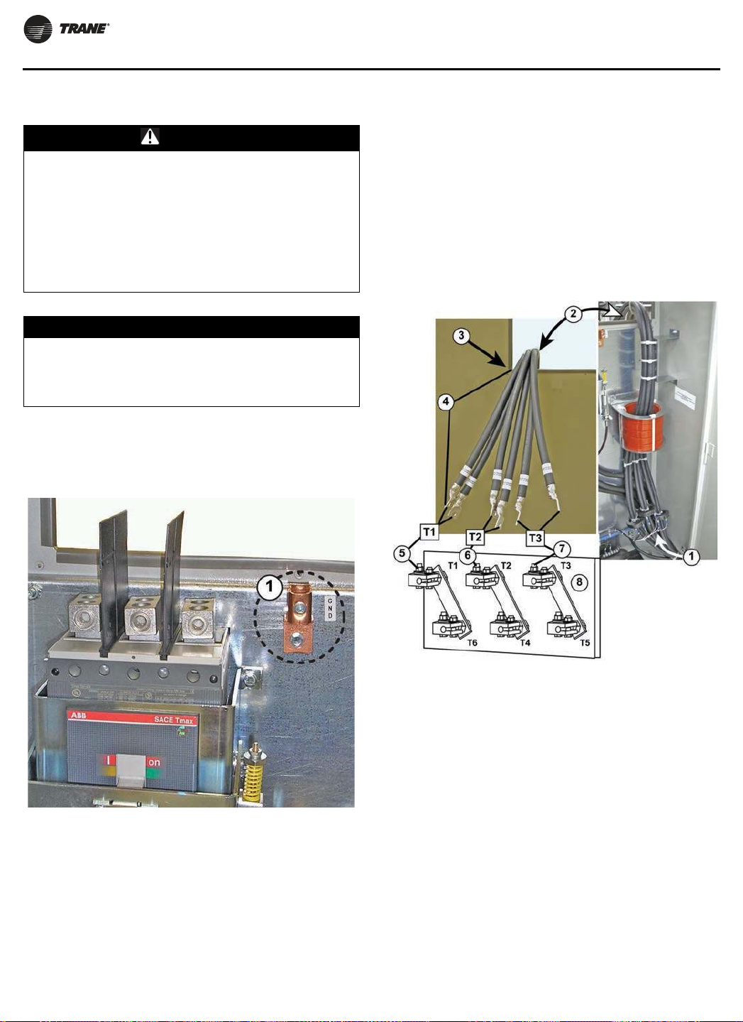
Installation
Grounding AFDH Cabinet
WARNING
Proper Field Wiring and Grounding
Required!
Failure to follow code could result in death or serious
injury. All field wiring MUST be performed by qualified
personnel. Improperly installed and grounded field
wiring poses FIRE and ELECTROCUTION hazards. To
avoid these hazards, you MUST follow requirements for
field wiring installation and grounding as described in
NEC and your local/state electrical codes.
NOTICE
Use Copper Conductors Only!
Failure to use copper conductors could result in
equipment damage as the equipment was not designed
or qualified to accept other types of conductors.
Run a suitable, unbroken, grounding conductor from the
drive cabinet’s ground connection terminal to the motor’s
ground terminal, and then on to earth ground.
Figure 40. Location of AFDH cabinet ground terminal
3. Attach the leads in pairs to the correct motor terminals
(both
T1 leads to the T1 terminal, both T2 leads to the
T2 terminal, and both T3 leads to the T3 terminal).
a. Torque the 3/8-inch bolts at each terminal
connection to 44 foot-pounds.
Note: These power connections should be re-torqued to
44 foot-pounds after the first three to six months of
operation and then on an annual basis thereafter.
4. Put the transition cover backin place and reseal itwhen
finished.
Figure 41. Output wiring from AFDH to CTV motor
1. Out pu t m ot or leads co ming i n fr om t he right ha nd cabin et
com p ar tm e nt ( d ri ve m od ul e) an d r out ed u p t o t h e mo t or t er m in al
acce ss cut out
2. Mot or lead s ro ut ed th rou gh cabi net m ot or ter mi nal acc ess cu to ut
3. Tra nsiti on cover rem oved and Z br acke t b lanked ou t o f p hot o f or
clarity
4. Fact ory i nst alled m otor leads ar e l on g enough to ex t end
approxi m at ely 1 8- inch es out fr om the access cu t out
5. Att ach b ot h T1 m ot or leads t o com pre ssor m otor t ermi nal T1
6. Att ach b ot h T2 m ot or leads t o com pre ssor m otor t ermi nal T2
1. Cabin et g ro un d connect ion t er mina l
7. Att ach b ot h T3 m ot or leads t o com pre ssor m otor t ermi nal T3
Com pr essor m ot or t erm in al bo ard
Output Wiring from the AFDH to the CTV
Motor
1. Remove the cover plate from the motor terminal
access cutout on the back of the drive cabinet.
2. Feed the six motor leads through the back of the drive
cabinet to the compressor motor terminal board.
48 AFDH-SVN004C-EN
Page 49

Installation
Routing of Control Wiring to
AFDH Cabinet
NOTICE
Route Incoming Power Conduit to the
Roof of the AFDH Cabinet!
Routing the incoming power conduit into the AFDH
cabinet anywhere other than through the specified
location on the cabinet roof, will be considered an
unsupported field modification to the cabinet design.
The air-cooled AFDH drive is designed to have the
incoming power conduit routed vertically into the unit
through the removable conduit connection cover
located on the left-hand rear corner of the cabinet roof.
If the starter that is being replaced by the AFDH drive
has the incoming power conduit routed horizontally
across the top of the starter, or connected to the side or
to the bottom of the starter cabinet, an electrician will
be required to reconfigure the conduit and wiring.
Figure 42. Wiring connections to 2X1 terminal strip in AFDH
1
NOTICE
Keep Dirt, Debris, or Metal Filings From
Entering the Drive Cabinet!
Failure to observe the appropriate precautions could
result in damage to the electrical components when
they are energized for the first time. Take all precautions
necessary to prevent any dirt, debris, or metal filings
from entering into the drive cabinet during the
installation process.
Control Wiring Connections
(Tracer® AdaptiView™ Model
AFDH Only)
2
2X1
4
5
6
7
3
8
9
10
1A
2A
4B
9A
10A
3D
4C
34
5
67
8910
11
34
5
67
8910
11
205A
208A
209A
401B
402B
203A
203B
207A
207B
2X2
11
12
13
JUHHQ
EODFN
ZKLWH
12
3
12
3
410A
411A
412A
AFDH-SVN004C-EN 49
Page 50

Installation
1. Fact ory i nst alled w ir in g
2. Field in st all ed wiri ng
3.
N ot e: Act ual wi re des ign ato rs ma y var y depe ndi ng up on th e sp ecif ic mo del/ v ers ion of chi lle r c ont ro l t hat t h e AFDH dr ive is bei ng lin ked w ith .
Please refer to th e o rig inal ch ille r cont ro l w iri ng dia gra ms and t he wir e d escr ipt ion s li sted in Fig ure Call out s 4 –11 if a n a ctu al wir e d esig nat or
does n ot m at ch the one sh ow n in t hi s g raphi c.
4. 1 15VAC f eed t o chi lle r con trol p ane l
5. N eut ral fe ed to chil ler cont rol pa nel
6. N orma lly Closed term inal (2 ) on HPC (High Pre ssur e Cut out ) sw it ch ( 3S1 ) f or or igin al chiller with sta rt er modu le an d/ or no n- com m. D ri ve
term ina l 4 is 1 15 VAC o nly.
Note: For ori gina l ch illers wit h a comm un icat ing dr ive , h igh pr essur e cutout w iring is 24V. For ori gina l ch illers wit h a st art er mod ule, high pressur e cu to ut
wi ri ng is 1 15V.
7. Fr om 1A7 J2-4 o il pu m p LLID
8. Fr om 1A7 J2-2 o il LLI D or cou ld co me f ro m t he 1X1 te rm inal b lock
9. a nd 1 0. No rm al close d term inal on HPC swi tch (3 S1) fo r or igi nal chil ler w it h co mm. Dri ve t er mina ls 9 and 1 0 ar e 2 4VDC only.
Note: For ori gin al ch iller s wi th a com muni cat in g d ri ve, high pr essu re cutout w ir ing is 24V.
11 . 12 . an d 13 . From UC80 0 I MC Modbu s lin k
Important: If the chiller does not already have a
condenser pressure transducer. Do not
forget to install the condenser pressure
Required Reprogramming of
Tracer® AdaptiView™ Controls.
transducer provided in the Tracer®
AdaptiView™ Miscellaneous Hardware
Package. The accurate pressure readings
required by the chillercontrols to enable the
most efficient operation of the chiller with
the upgraded AFDH drive can only be
effectively measured with a pressure
transducer.
Reprogramming Factory Installed Tracer®
AdaptiView™ Controls (CTV Simplex
Firmware)
Important: Make sure your laptop is loaded with the
most current version of Tracer TU tool
software so that you have the most up-todate version of CTV MP firmware available
to install into the UC800.
Note: CTV
MP firmware is always usedin factoryinstalled
Tracer® AdaptiView™ control systems or in
Tracer® AdaptiView™ display upgrades to factory
installed CH530 control systems.
Table 26. UC800/Tracer® AdaptiView™ CTV parameter values with upgrade AFDH
Tr a cer TU Se rv ice S et poi nt s V ie w :
Ad just ab le Fre qu en cy Dri ve S et poi nts
AF Con trol Aut o, Fixed Aut o Aut o
ReOpt imi zat io n Sensit iv it y 0– 10 0% 2 0 20
Tr a cer TU Fi eld St a rt up V ie w :
Ad just ab le Fre qu en cy Dri ve
AFD Tem pe rat ure Limi t Set poin t 0 .0 - 36 0. 0 21 2. 0 21 2. 0
Max im um Frequ ency 3 0– 60 H z 60 60
Min im um Fre quency 30 –6 0 Hz 3 8 38
Sur ge Speed I ncr ease 0– 2 Hz 1 1
Tr a cer TU Co nf ig ura t io n Vi ew : Mai n R an ge De fau lt Se tti ng Re com m en ded Sett ing
Uni t Type ( MODL) CVHE, CVHF, CVHG, CVGF CVHE
Tr a cer TU Co nf ig ura t io n Vi ew : UC8 00
St arter Type Not App licable Uni t Mou nt Wye -D elt a TR200 Modbu s AFD
I m pel ler D iam ete r (CPI M) 50 - 34 5 27 5 Enter CPI M f ro m Un it Na m epl at e
Tr a cer TU Co nf ig ura t io n Vi ew : St art er Ra nge Def ault Se tti ng Re com m end ed S et ting
Uni t Lin e Volt age 18 0– 15 00 0V 46 0 Ent er f rom Unit Name pla te
Mot or NP Pow er 40 00 k W 400 Enter fr om Unit Nam epla te
Mot or Tem perat ure Pro te ction Type 75 Oh m @75 F, 100 Ohm @ 0 C 75 ohm 7 5 oh m
Ra nge Def ault Se tti ng Re com m end ed S et ting
Ra nge Def ault Se tti ng Re com m end ed S et ting
Ent er Chill er Model fr om Unit Name plat e
( Not e: on ly CVHE or CVHF a pply)
Ra nge Def ault Se tti ng Re com m end ed S et ting
50 AFDH-SVN004C-EN
Page 51

AFDH Startup Procedure
Follow the procedure below when starting the water chiller
and drive.
1. The CenTraVac™ chiller control starts, stops, and
monitors all unit and AFDH run functions.
Complete all items on the commissioningchecklistand
in the startup procedures for the CVHE and CVHF as
defined in the operation maintenance manual or other
applicable manual.
WARNING
Hazardous Voltage w/Capacitors!
Failure to disconnect power and discharge capacitors
before servicing could result in death or serious injury.
Disconnect all electric power, including remote
disconnects and discharge all motor start/run
capacitors before servicing. Follow proper lockout/
tagout procedures to ensure the power cannot be
inadvertently energized. Forvariable frequency drivesor
other energy storing components provided by Trane or
others, refer tothe appropriate manufacturer’s literature
for allowable waiting periods for discharge of
capacitors. Verify with an appropriate voltmeter that all
capacitors have discharged.
DC bus capacitors retain hazardous voltages after input
power has been disconnected. Follow proper lockout/
tagout procedures to ensure the power cannot be
inadvertently energized. after disconnecting input
power, wait ten (10) minutes for the dc capacitors to
discharge and then check the voltage with a voltmeter
to ensure the dc bus capacitors are discharged before
touching any internal components. Failure to observe
this precaution could result in death or serious injury.
For additional information regarding the safe discharge
of capacitors, see PROD-SVB06*-EN.
2. Check the following on the drive:
a. Make sure input wire sizing to the drive is sized
correctly
connected as noted in this manual.
b. Check the drive ground connection; check cabinet
wire routing and grounding.
3. Check all drive wiring and connections in the drive to
make
damage.
4. AFDH control checkout:
a. CHILLER Setpoints: As with any new chiller, first
check out all setpoints for the chiller.
b. AFD Setpoints: Check out all AFD setpoints (refer to
“Drive Settings,”).
c. AFD Configuration: Verify the correctness of the
“Sales Order” specific setpoints in the “Starter
Configurations for AFDStarters.”Thesesettingsare
specific to unit/motor combination in the drive. All
of the remaining settings are factory-determined
based on unit nameplate voltage, and
sure they are tight and free of any shipping
default setpoints that are the same on all AFDH aircooled drives.
Note: If
5. When ready, start the drive from the chiller display.
6. Document all information on the startup log.
the set values do not match, contact the
local Trane Service agency first, or the
Global Parts Technical Service Department.
The correct values are listed on the unit
nameplate shipped with each unit.
Drive Settings
Important: Any AFDH drive module menu parameter
numbers not listed in this manual are nonTrane specific program parameters. All
non-Trane specific program parameter
values have been set by the manufacturer
before shipment, to provide optimum drive
performance. Under no circumstances
should any of the pre-set values in these
menu parameters be changed unless
specifically directed to do so by a factory
engineer or a factory technical support
person.
Note: Please
For additional information, refer to the programming
manual
manual includes a detailed section that discusses
accessing the parameters in the drive.
This process is summarized briefly below:
1. To access the parameters, press the Main Menu key.
2. If required, enter the password (999).
3. To select a parameter group, use the up/down arrow
keys
the Enter key to access that group.
4. Use the up/down arrow keys to access the parameter
number, and then press the OK key.
5. Use the up/down arrow keys to change the parameter,
and
refer to the BAS-SVP04*-EN (
Guide: TR200
program parameter details and descriptions, and
the instructions necessary to operate the Local
Control Panel (LCP) and program the necessary
drive parameters.
that is shipped with the drive. The programming
to highlight the parameter group, and then press
then press the OK key to change the setting.
), or the most recent version, for full
Programming
AFDH-SVN004C-EN 51
Page 52

AFDH Startup Procedure
TR200 Drive Configuration
Note: Technician may elect to configure the drive by
using Danfoss VLT Motion Control tool MCT10.
Follow the following steps:
1. If the TDU Drive Utility Program is installed on your
laptop: You must first uninstall the TDU Drive Utility in
order to install the MCT 10 software.
2. Install MCT 10 toll: HUB Document DOC-155220: MCT
10 Installation Instructions.docx (Danfoss VLT Motion
Control Tools MCT 10 Set-up Software manual)
3. Configure the TR200 drive using MCT 10 tool: HUB
Document DOC-179427: Creating a Project a Master
File and Configuration for AFDH D & E-Frame
Drive.docx (AFDH D & E-Frame Drive Configuration
Instructions Using MCT 10 Tool).
To manually configuring the drive, you should ensure the
drive
is at the default sittings by performing the following
procedures to reset the drive:
1. Disconnect power to the drive, and wait for the display
to shut down.
2. While powering up the drive, press and hold the
following
3. After 5 seconds, release the keys.
After the drive is reset, reprogram the items listed in the
below
Table 27. Job specific settings
keys: Status, Main, and OK.
tables.
Table 28. Trane default settings (continued)
Gr ou p Par a m e ter D escr ip t io n Se tti ng
1 03 Tor que chara cteri stics Var iable t or que ( 1)
1 22 Mot or v olta ge Nam epl at e vol tage
1 23 Mot or f re qu ency 6 0 Hz
1 39 Mot or p ole s Poles (2)
3 02 Min im um Refe rence 30 Hz
3 03 Max im um Refere nce 6 0 Hz
3 15 Referen ce 1 Sou rce No Funct ion
3 16 Referen ce 2 Sou rce No Funct ion
3 41 Ram p 1 ram p u p tim e 1 0 sec
3 42 Ram p 2 ram p d ow n tim e 20 sec
4 12 Mot or speed l ow li m it 3 8 Hz
4 14 Mot or speed h ig h lim it 60 Hz
5 12 Ter m in al 27 Digit al Input No operat ion ( 0)
5 40. 1 Funct ion Rel ay Running
8 01 Contr ol Sit e Contr olwor d only (2 )
8 03 Contr ol Tim eout Tim e 1 5 sec
8 0 4 Con tr ol Ti m eou t Fun ct io n St op
8 30 Prot ocol Modb us RTU
8 31 Add re ss 3
8 32 Bau d Rate 38 40 0 Bau d
8 33 Parity / St op Bi ts No Parity, 1 St op Bit
836
14 21 Aut om at ic Rest ar t Tim e 1 0 sec
Max im um Response
Del ay
10 0
Gr ou p Pa r am ete r Descripti on Va lue
1 20 Mo tor kW Set to name pla te NMKW
1 24 Mo tor Cur re nt Set t o nam epla te NMRA
1 25 Mo tor Nom inal sp eed Set t o nam eplat e TRPM
4 16 Tor que l im it m ode Set t o ma xi mum
4 18 Cu rr en t limi t Set t o m aximu m
Table 28. Trane default settings
Gr ou p Par a m e ter D escr ip t io n Se tti ng
0 20 Displa y lin e 1. 1 sm all
0 21 Displa y lin e 1. 2 sm all
0 22 Displa y lin e 1. 3 sm all
0 23 Displa y lin e 2 lar ge
0 24 Displa y lin e 3 lar ge Fr eq Hz (1613)
032
0 40 Han d on key Disabl ed ( 0)
0 41 Off k ey Disab led ( 0)
0 60 Main Menu p assw or d 9 99
061
Cust om Read out Max
Valu e
Access t o m ain m enu w /
o passw or d
DC lin k volt age
( 16 30 )
Mot or Cu rr en t
( 16 14 )
Heat sin k tem p
( 16 34 )
I np ut Pow er Kw
( 16 10 )
Nam epla te NMRA
LCP; Read on ly ( 1)
After all settings are made save a copy chiller service
report for future use.Recommend that Trane Techsload to
ComfortSite by chiller serial number.
52 AFDH-SVN004C-EN
Page 53

Troubleshooting
The drive displays three types of faults:
• Warning
A warning oralarm is signaledby the LEDson the front
of the AFD by a code on the LCP.
A warning indicates a condition that may require
attention or a trend that may eventually require
attention, and will remain active until the cause is no
longer present. Under some circumstances, motor
operation may continue.
• Trip
A trip is the action when an alarm has appeared. The
trip removes power to the motor and, after the
condition has been cleared, can be reset by pressing
the Reset button. The event that caused an alarm
cannot damage the AFD or cause a dangerous
condition.
After its cause has been rectified, an alarm must be
reset
to restart operation.
• Trip Lock
A trip lock is an action when an alarm occurs that may
damage to the AFD or equipment. Power is
cause
removed from the motor, and a trip lock can only be
reset after the condition is cleared by cycling power.
Once the problem has been rectified, only the alarm
continues flashing until the AFD is reset.
2. Collect chiller information.
a. Note the following chiller information:
• Operating
or 75% load etc.)
• Number of chiller starts, and hours of operation.
• Time
<1 hour, >1 hour, etc.)
b. What was the chiller state at the time of the failure?
(Chiller starting? Running low load? Running full
load? etc.)
c. Record the chiller’s sales order and serial numbers,
and
the drive’s serial and model numbers.
3. Troubleshooting
a. Measure and record the DC bus (via the Local
Control
b. Check ALL wiring (tightness, ribbon cables fully
seated, proper phasing, etc.)
c. Refer to the Danfoss manuals for further
troubleshooting information.
mode and any sub-mode (i.e., 100%
since last diagnosticshutdown (<1 minute,
Panel [LCP]).
WARNING
Hazardous Voltage w/Capacitors!
Failure to disconnect power and discharge capacitors
before servicing could result in death or serious injury.
Disconnect all electric power, including remote
disconnects and discharge all motor start/run
capacitors before servicing. Follow proper lockout/
tagout procedures to ensure the power cannot be
inadvertently energized. Forvariable frequency drivesor
other energy storing components provided by Trane or
others, refer tothe appropriate manufacturer’s literature
for allowable waiting periods for discharge of
capacitors. Verify with a CAT III or IV voltmeter rated per
NFPA 70E that all capacitors have discharged.
For additional information regarding the safe discharge of
capacitors, see PROD-SVB06*-EN.
1. Tracer® AdaptiView™ only: Collect alarm and
parameter information.
a. DO NOT cycle unit power or reset the controls.
Leave the AFD and the UC800 in their present
states.
b. Record all UC800 active and historic alarms. Make
a
full chiller service report.
c. Document and check all applicable parameter
settings. This information can be verified off of the
chiller nameplate, and by referring to this manual..
AFDH-SVN004C-EN 53
Page 54

Startup Test Log
Water-Cooled CenTraVac Chiller with Tracer® AdaptiView™ Control and
Adjustable Frequency Drive (AFD) Starter
Job Nam e AFD Se rial Num ber
Job Locati on AFD Model Num be r
Sales Order Numb er Shi p Dat e
Chiller Ser ial Nu m ber St art Dat e
Chiller Model Num ber
54 AFDH-SVN004C-EN
Page 55

Recommended Periodic Maintenance and Inspection
Inspection Frequency
Perform inspections outlined below every 1 to 12 months,
depending on operating environment.
Visual Inspection—Power
Removed
WARNING
Hazardous Voltage w/Capacitors!
Failure to disconnect power and discharge capacitors
before servicing could result in death or serious injury.
Disconnect all electric power, including remote
disconnects and discharge all motor start/run
capacitors before servicing. Follow proper lockout/
tagout procedures to ensure the power cannot be
inadvertently energized. Forvariable frequency drivesor
other energy storing components provided by Trane or
others, refer tothe appropriate manufacturer’s literature
for allowable waiting periods for discharge of
capacitors. Verify with a CAT III or IV voltmeter rated per
NFPA 70E that all capacitors have discharged.
For additional information regarding the safe discharge of
capacitors, see PROD-SVB06*-EN.
1. Ensure the door interlocks are present and working.
2. Verify the safety ground connections to the door
are securely connected.
panels
3. Inspect power wire cables and devices to assure no
abrasion is occurring from vibrations against chassis
of cabinets, or other edges.
4. Ensure the drive interior and exterior is clear of any
dust or debris. Fans, circuit boards, vents etc. must be
clean. Only use a vacuum for cleaning. DO NOT use
compressed air. Review actual operation environment
against specs if any concern.
5. Inspect the interior of the drive for any signs of
moisture
6. Visually inspect alldrive components andwiring. Look
for
capacitors, discolored reactors or inductors, broken
pre-charge resistors, smoke or arc trails on MOVs and
capacitors, etc.)
7. Closely inspect the motor terminal board for any signs
of
8. Check ALL cable/lug/terminal connections inside the
drive enclosure. Ensure all are clean and tight, and not
rubbing against each other anywhere.
entry or leakage.
signs of heat or failure (look for swelled or leaking
leakage, arcing, etc.
Operational Inspection—Power
Applied
WARNING
Live Electrical Components!
Failure to follow all electrical safety precautions when
exposed to live electrical components could result in
death or serious injury. When necessary to work with
live electrical components, have a qualified licensed
electrician or other individual who has been properly
trained in handling live electrical components perform
these tasks.
1. Verify the drive cabinet cooling fans are operating.
This should be done from outside the enclosure, by
looking into the cabinet at door and cabinet vents, to
avoid electrical hazards.
Note: The power module fan comes on with power.
Other fans cycle with drive operation.
2. Check historic fault codes using Local Control Panel
(LCP) connected to the AFD.
3. Check configuration settings and confirm all proper
settings are still present in the controls.
4. Review the diagnostic history.
5. Make Chiller Service report to document all setpoints.
6. Check the UC800 alarm histories for any indications of
operational
To properly diagnose service issues for Adaptive
Frequency drives for centrifugal chillers equipped with
AFDH starters. AllUC800 chillers willbe equipped withthe
LCP as standard on the drive power module. This is for
service only and NEVER for machine operation.
problems.
Air Filter
Clean or replace filter every 1 to 12 months, depending on
operating environment.
Filt er Descri pti on Pa rt Num be r
Direct Mount D rive Air Fil ter FLR08 81 4
Transit ion Mo un t Dr iv e Air Filt er FLR08814
Liq uiFlo 1 .0 / 1.5 D rive Air Filter FLR08814
AFDH-SVN004C-EN 55
Page 56

Wiring Diagram Matrix
W iri ng Diag r am
N um be r
50 71 21 27 Cen TraVac™ W ir ing D iag ram wit h Dan foss
Note: Wir ing d iag rams are ava ila ble via e-Libr ary.
Descripti on
Ada pt iv e Fr equen cy Dr iv e
56 AFDH-SVN004C-EN
Page 57

Page 58

Page 59

Page 60

Trane - by Trane Technologies (NYSE: TT), a global climate innovator - creates comfortable, energy
efficient indoor environments for commercial and residential applications. For more information,
please visit trane.com or tranetechnologies.com.
Trane has a policy of continuous product and product data improvement and reserves the right to change design and specifications without
notice. We are committed to using environmentally conscious print practices.
AFDH-SVN004C-EN 11 May 2020
Supersedes AFDH-SVN004B-EN (Jan 2020)
©2020 Trane
 Loading...