

Page 1

Installation Instructions
Roof Curbs for Performance Climate Changer™
Air Handlers
Model CSAA and PSCA
Only qualified personnel should install and service the equipment. The installation, starting up, and servicing
of heating, ventilating, and air-conditioning equipment can be hazardous and requires specific knowledge and
training. Improperly installed, adjusted or altered equipment by an unqualified person could result in death or
serious injury. When working on the equipment, observe all precautions in the literature and on the tags,
stickers, and labels that are attached to the equipment.
May 2018
SAFETY WARNING
CLCH-SVN05C-EN
X-39641204010
Page 2

Introduction
Read this manual thoroughly before operating or servici ng
this unit.
Warnings, Cautions, and Notices
Safety advisories appear throughout this manual as
required. Your personal safety and the proper operation of
this machine depend upon the strict observance of these
precautions.
The three types of advisories are defined as follows:
WARNING
CAUTIONs
NOTICE
Important Environmental Concerns
Scientific research has shown that certain man-made
chemicals can affect the earth’s naturally occurring
stratospheric ozone layer when released to the
atmosphere. In particular, several of the identified
chemicals that may affect the ozone layer are refrigerants
that contain Chlorine, Fluorine and Carbon (CFCs) and
those containing Hydrogen, Chlorine, Fluorine and
Carbon (HCFCs). Not all refrigerants containing these
compounds have the same potential impact to the
environment. Trane advocates the responsible handling of
all refrigerants-including industry replacements for CFCs
and HCFCs such as saturated or unsaturated HFCs and
HCFCs.
Important Responsible Refrigerant
Practices
Trane believes that responsible refrigerant practices are
important to the environment, our customers, and the air
conditioning industry. All technicians who handle
refrigerants must be certified according to local rules. For
the USA, the Federal Clean Air Act (Section 608) sets forth
the requirements for handling, reclaiming, recovering and
recycling of certain refrigerants and the equipment that is
used in these service procedures. In addition, some states
or municipalities may have additional requirements that
must also be adhered to for responsible management of
refrigerants. Know the applicable laws and follow them.
Indicates a potentially hazardous
situation which, if not avoided, could
result in death or serious injury.
Indicates a potentially hazardous
situation which, if not avoided, could
result in minor or moderate injury. It
could also be used to alert against
unsafe practices.
Indicates a situation that could result in
equipment or property-damage only
accidents.
WARNI NG
Proper Field Wiring and Grounding
Required!
Failure to follow code could result in death or serious
injury. All field wiring MUST be performed by qualified
personnel. Improperly installed and grounded field
wiring poses FIRE and ELECTROCUTION hazards. To
avoid these hazards, you MUST follow requirements for
field wiring installation and grounding as described in
NEC and your local/state electrical codes.
WARNI NG
Personal Protective Equipment (PPE)
Required!
Failure to wear proper PPE for the job being undertaken
could result in death or serious injury. Technicians, in
order to protect themselves from potential electrical,
mechanical, and chemical hazards, MUST follow
precautions in this manual and on the tags, stickers,
and labels, as well as the instructions below:
• Before installing/servicing this unit, technicians
MUST put on all PPE required for the work being
undertaken (Examples; cut resistant gloves/sleeves,
butyl gloves, safety glasses, hard hat/bump cap, fall
protection, electrical PPE and arc flash clothing).
ALWAYS refer to appropriate Material Safety Data
Sheets (MSDS)/Safety Data Sheets (SDS) and OSHA
guidelines for proper PPE.
• When working with or around hazardous chemicals,
ALWAYS refer to the appropriate MSDS/SDS and
OSHA/GHS (Global Harmonized System of
Classification and Labelling of Chemicals) guidelines
for information on allowable personal exposure
levels, proper respiratory protection and handling
instructions.
• If there is a risk of energized electrical contact, arc, or
flash, technicians MUST put on all PPE in accordance
with OSHA, NFPA 70E, or other country-specific
requirements for arc flash protection, PRIOR to
servicing the unit. NEVER PERFORM ANY
SWITCHING, DISCONNECTING, OR VOLTAGE
TESTING WITHOUT PROPER ELECTRICAL PPE AND
ARC FLASH CLOTHING. ENSURE ELECTRICAL
METERS AND EQUIPMENT ARE PROPERLY RATED
FOR INTENDED VOLTAGE.
© 2018 Ingersoll Rand CLCH-SVN05C-EN
Page 3
WARNING
Follow EHS Policies!
Failure to follow instructions below could result in
death or serious injury.
• All Ingersoll Rand personnel must follow Ingersoll
Rand Environmental, Health and Safety (EHS)
policies when performing work such as hot work,
electrical, fall protection, lockout/tagout, refrigerant
handling, etc. All policies can be found on the BOS
site. Where local regulations are more stringent than
these policies, those regulations supersede these
policies.
• Non-Ingersoll Rand personnel should always follow
local regulations.
Copyright
This document and the information in it are the property of
Trane, and may not be used or reproduced in whole or in
part without written permission. Trane reserves the right
to revise this publication at any time, and to make changes
to its content without obligation to notify any person of
such revision or change.
Introduction
Trademarks
All trademarks referenced in this document are the
trademarks of their respective owners.
Revision History
Updated dimensional data.
CLCH-SVN05C-EN 3
Page 4

Table of Contents
Introduction . . . . . . . . . . . . . . . . . . . . . . . . . . . . . 5
Overview of Manual . . . . . . . . . . . . . . . . . . . 5
Nameplate . . . . . . . . . . . . . . . . . . . . . . . . . . . . 5
Pre-Installation . . . . . . . . . . . . . . . . . . . . . . . . . . 6
Site Preparation . . . . . . . . . . . . . . . . . . . . . . . 6
Roof Curb Installation Checklist . . . . . . . . . . 6
Dimensions and Weights . . . . . . . . . . . . . . . . . 7
Installation . . . . . . . . . . . . . . . . . . . . . . . . . . . . . . 8
Placement . . . . . . . . . . . . . . . . . . . . . . . . . . . . 8
Assembly and Installation . . . . . . . . . . . . . 10
Unit Roof Curb . . . . . . . . . . . . . . . . . . . . . 10
Pipe Cabinet Roof Curb . . . . . . . . . . . . . . 12
Specialty Roof Curbs . . . . . . . . . . . . . . . . 12
Ductwork Recommendations . . . . . . . . . . . 13
Sound Attenuation . . . . . . . . . . . . . . . . . . 13
Supply and Return Air Ductwork . . . . . . 14
Parts Information . . . . . . . . . . . . . . . . . . . . . 15
4 CLCH-SVN05C-EN
Page 5
Introduction
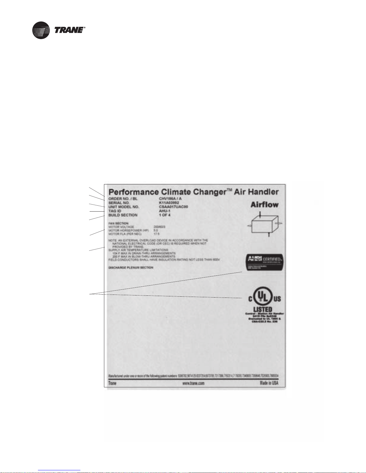
Agency listings and/or
agency certifications
Trane order number
Unit level serial number
Service model number
Unit tagging
Section location
Functional section type
Notes and additional
section information
Overview of Manual
Performance Climate Changer™ air handlers may be
mounted on the roof with a roof curb or pier mount. This
manual includes the assembly instructions. Before
proceeding with the installation, refer to the unit submittal
drawings and unit tagging for correct placement of air
handler sections. Failure to review the submittal drawings
could result in performance or assembly problems. If there
are any discrepancies, contact your local Trane sales
engineer before proceeding. Carefully review the
procedures discussed in this manual to minimize
installation and startup difficulties.
Figure 1. Performance air handler section nameplate
Nameplate
Each air handler section includes at least one nameplate/
label, which identifies the type of section and functional
components, customer tagging information, the unit
serial number, the unit order number, the build section
position for installation, and the unit model number. Refer
to this information when ordering replacement parts or
requesting service.
Note: The unit serial number and order number is
required when ordering parts or requesting service
for a Trane air handler.
CLCH-SVN05C-EN 5
Page 6

Pre-Installation
As-built submittals show the intended layout of the
various air handler sections to meet job site requirements.
Installation information (unit dimensions, clearances,
weights, curb location and roof opening dimensions and
locations) may vary with special equipment and
applications. For exact information, always refer to the
specific unit submittals, which can be obtained from your
local Trane sales office.
Roof curbs are shipped “knocked down” for assembly at
the job site.
Site Preparation
Ensure the installation site can support the total weight of
the air-handling unit, including accessories and the roof
curb. For approximate air handler section weights, refer to
Performance Climate Changer™ Air Handler IOM, CLCHSVX07*-EN. Units with special options or arrangements
will differ in dimensions, clearances, weights and roof
opening dimensions and locations. Always refer to unit
submittals before marking off the dimensions of the unit
roof curb, pipe ca binet curb (if pipe cabinet is ordered),
and roof openings. For roof curbs supplied by Trane,
approximate roof curb weights are in Tab le 1 .
Note: To calculate the total curb weight, find the unit
length, multiply by the factor supplied in Tab l e 1 for
the applicable roof curb height, and add the curb
end weight for the applicable roof curb height.
Roof Curb Installation Checklist
It is recommended that the curb be installed directly on the
support members and fastened to the supports using tack
welds or other equivalent methods. Properly supported
decking should be installed inside the air handler section
of the curb when this method is used.
Verify that the roof structure can adequately support
the combined weight of the unit and curb assembly.
Ensure that the selected installation location provides
sufficient service and operational clearances.
Remove any twist within the curb due to roof supports
and square the curb.
Level the curb.
Secure the curb to the roof support members.
Install 2-inch thick boards or rigid insulation around the
curb.
Install cant strips around the curb.
Bring field supplied roofing felt up to the top of the
curb nailing strips. Nail felt into place.
Install field supplied flashing under the lip of the curb
flanges and over the felt.
Apply sealant to the four corners.
Caulk all joints between the curb and the roof. Attach
the gasket material to the curb’s top flanges (entire
perimeter) and to the supply and return air duct open
panel flanges.
6 CLCH-SVN05C-EN
Page 7

Dimensions and Weights
Table 1. CSAA Curb weights
Curb
height
14-inch
18-inch
22-inch
26-inch
30-inch
36-inch
Curb
height Unit Size 30 35 40 50 57 66 80 100 120
14-inch
18-inch
22-inch
26-inch
30-inch
36-inch
Note: Example: Size 21 Performance air handler with airfoil damper mixing section, small coil section, medium access section, medium coil section, small
blank section, VFD control section, and fan section (down discharge) total unit length is 156.75 inches. Total roof curb weight for the 18-inch curb
would be 502.80 lbs (156.75 x 1.05 = 164.5875 lbs + 338.21 = 502.7975 lbs.)
Unit Size 3 4 6 8 10 12 14 17 21 25
Curb end and duct
support weight
Curb side weight Take total length in inches, multiply by 0.56 pounds, and add to the above curb end & duct support weight.
Curb end and duct
support weight
Curb side weight T ake total length in inches, multiply by 1.05 pound s, and add to the abov e curb end & duct sup port weight.
Curb end and duct
support weight
Curb side weight Take total length in inches, multiply by 1.22 pounds, and add to the above curb end & duct support weight.
Curb end and duct
support weight
Curb side weight T ake total length in inches, multiply by 2.00 pound s, and add to the abov e curb end & duct sup port weight.
Curb end and duct
support weight
Curb side weight Take total length in inches, multiply by 2.25 pounds, and add to the above curb end & duct support weight.
Curb end and duct
support weight
Curb side weight T ake total length in inches, multiply by 2.63 pound s, and add to the abov e curb end & duct sup port weight.
Curb end and duct
support weight
Curb side weight Take total length in inches, multiply by 0.56 pounds, and add to the above curb end & duct support weight.
Curb end and duct
support weight
Curb side weight T ake total length in inches, multiply by 1.05 pound s, and add to the abov e curb end & duct sup port weight.
Curb end and duct
support weight
Curb side weight Take total length in inches, multiply by 1.22 pounds, and add to the above curb end & duct support weight.
Curb end and duct
support weight
Curb side weight T ake total length in inches, multiply by 2.00 pound s, and add to the abov e curb end & duct sup port weight.
Curb end and duct
support weight
Curb side weight Take total length in inches, multiply by 2.25 pounds, and add to the above curb end & duct support weight.
Curb end and duct
support weight
Curb side weight T ake total length in inches, multiply by 2.63 pound s, and add to the abov e curb end & duct sup port weight.
117.23 155.82 155.82 175.88 209.84 225.27 242.25 242.25 266.94 266.94
148.76 197.59 197.59 222.98 265.95 285.48 306.96 306.96 338.21 338.21
171.54 227.14 227.14 256.05 304.98 327.22 351.68 351.68 387.26 387.26
215.31 286.02 286.02 322.78 385.00 413.28 444.39 444.39 489.64 489.64
240.72 319.23 319.23 360.06 429.15 460.56 495.11 495.11 545.36 545.36
278.82 369.05 369.05 415.98 495.38 531.48 571.18 571.18 628.93 628.93
308.62 328.68 367.27 407.39 407.39 453.70 453.70 496.91 581.80
390.95 416.34 465.17 515.95 515.95 574.54 574.54 629.23 736.65
447.31 476.22 531.82 589.64 589.64 656.36 656.36 718.63 840.95
566.00 602.77 673.47 747.00 747.00 831.85 831.85 911.03 1066.58
630.15 670.98 749.50 831.15 831.15 925.37 925.37 1013.31 1186.04
726.38 773.30 863.54 957.38 957.38 1065.66 1065.66 1166.73 1365.24
CLCH-SVN05C-EN 7
Page 8

Installation
Discharge
Intake
Airflow
Auxillary support
loaded under curbs
Roof mounting curb
inside edge
Main roof support member
capable of supporting unit
weight
Main roof support member
or auxillary support located
under center of unit or under
section joints
Piers
4 ft
Placement
Note: Isolation rails should not be installed on top of
Trane roof curbs. If isolation rails or isolation curbs
are required, the entire curb system should be
supplied by a specialty curb company.
The roof curb must be supported along its entire
perimeter. The curb may be set parallel or at right angles
to roof support members. If at right angles to the support
members, there must be adequate supporting roof cross
members between the ends (in the direction of airflow). Be
sure the cross members do not interfere with the
connection of supply and return ducts to the unit. See
figure below for details.
Figure 2. Unit set perpendicular to roof curb members
Figure 3. Pier locations (typical)
Figure 4. Side view with shipping splits
• When mounting the unit on its roof curb, make sure
that the gasketing between the roof curb and unit base
provides an airtight seal.
Note: When pulling shipping split sections together, the
field-supplied gasket material may bunch up
between bases. Make certain this does not prevent
tight contact between shipping sections.
• If a unit is pier-mounted, at a minimum, locate one pier
at each corner directly underneath any shipping split
(ensure full support under each side), and then every
four feet at equally spaced intervals around the
perimeter of the unit. Both the unit and the pipe cabinet
should be supported by their base channel around the
entire perimeter (see Figure 3 and Figure 4).
8 CLCH-SVN05C-EN
Note: Piers beneath shipping splits must be structurally sound to support
the weight of the unit.
See Figure 5 for typical cross section for pier- or slabmounted base.
Page 9

Installation
3.0 in. - sizes 3-50
4.0 in. - sizes 57-120
6.0 in. - sizes 3-120
2 x 4
Nailer
Roof
curb
Gasket
Nail
Counter
flashing
Flashing
Roofing/insulating
material
Figure 5. Typical cross section for pier mounted or
slab-mounted base
Note: For PSCA, the base rail height is 7.25 in. Verify the base rail width
in unit submittal.
• For new building construction, the roof curb may be
installed as soon as the roof support members are in
place. Trane recommends that the roof curb be placed
directly on the roof support members and welded into
place. If the curb is mounted on the roof deck,
additional support is necessary directly below the curb
flanges to minimize vibration.
• Do not overlap counter flashing over the top of the roof
curb. Counter flashing should extend to the bottom of
the roof curb drip lip. Attach counter flashing with
fastener through the wooden nailer. Figure 6, Figure 7
and Figure 8 show typical roof curb installations and
detail.
Note: Materials that attach to the roof curb are supplied
by the installer, including flashing, insulating
material and cant. Gasket and 2 x 4 nailer are
supplied by Trane.
Figure 6. Typical roof curb installation - existing
building
Gasket
2 x 4 nailer
Roof curb
Wooden nailer
Roof structure
Nail
Counter flashing
Flashing
Roof/insulating material
4 x 4 cant
Roof insulation
Figure 7. Typical roof curb installation - new
construction
Gasket
2 x 4 nailer
Roof curb
Nail
Counter flashing
Flashing
Roof/insulating material
4 x 4 cant
Roof structure
Roof insulation
Roof deck
Figure 8. Detail of installation
Roof deck
CLCH-SVN05C-EN 9
Page 10

Installation
Assembly and Installation
The following procedure explains how to assemble and
install roof curbs provided by Trane. An attachment
specific to your roof curb is shipped with your Traneordered roof curb. See typical exploded view and parts list
in Figure 22, p. 15 and Tab l e 4 , p . 16 . In order to properly
locate the duct supports (if required) and external piping
cabinet (if ordered), it is recommended that you have a
copy of the as-built curb drawings from the submittal
package. For specialty or field-fabricated roof curbs please
see the section entitled “Specialty Roof Curbs,” p. 12 for
important information.
Unit Roof Curb
Figure 9. Typical roof curb provided by Trane
Figure 10. Side splice detail
Nut
Washer
Washer
Bolt
Splice
plate
2. Attach outer and inner corner splice plates (4 places) as
shown in the figure below.
Figure 11. Corner splice detail
Cross brace
WARNING
Risk of Roof Collapsing!
Failure to ensure proper structural roof support could
cause the roof to collapse, which could result in death
or serious injury and property damage. Confirm with a
structural engineer that the roof structure is strong
enough to support the combined weight of the roof
curb and the unit. Refer to “Dimensions and Weights,”
p. 7 for typical curb weights.
1. Attach cross brace and outer side splice plates at splice
locations (refer to the following figure).
Roof curb
Washer
Washer
Bolt
Nut
Inner corner
angle
Outer corner
angle
10 CLCH-SVN05C-EN
Page 11

Installation
A
B
C
D
79
61 1/4
8 7/8
17 3/4
38
13 1/2
14
9 1/2
23 1/8
37 7/8
5 1/2
15 7/8
19 7/8
55 5/8
134 1/4
155 7/8
75 1/2
Note: Open side of 1301 crossbrace
must face to the left.
Notes:
1. 1306-xx (PTAF duct support) is field cut to length.
2. Use self drillers (included) to attach 1307-xx (duct
support angle) to 1305-xx and 1606-xx.
1307-01
1305-01
1384-01
1301-01
1306-02
1305-02
1384-02
1385-01
1306-01
Unit roof curb
2 x 4 nailer
Pipe chase
roof curb
Roof curb
angle
Check curb dimensions for squareness as shown in the
figure below. Measurements from A-B should equal
measurement from C-D (± 1/8-inch).
Note: Measurements A-C, D-B, A-D, and B-C are inside
curb dimensions and are supplied with the unitspecific roof curb manual.
Figure 12. Unit roof curb perimeter
3. Tighten nuts/bolts at all locations. Ensure lock nuts are
securely tightened.
4. Review the details curb plan view as-built to determine
the location of the supply and/or return openings and
placement of duct support members. See figure below.
Figure 13. Typical as-built curb detail plan view (inches)
from submittal package
5. Attach duct support members to each side of roof curb
perimeter wall with self-drill screws. See figure below.
Figure 14. Duct support detail
6. Assemble the pipe cabinet roof curb (when supplied).
See the figure below.
Note: If pipe cabinet roof curb interferes with splice
plates, field drill holes to match those in the splice
plate. Attach the pipe cabinet roof curb with splice
plate bolts. Self-drill the other end.
Figure 15. Pipe cabinet roof curb assembly
CLCH-SVN05C-EN 11
7. Install gasket along the perimeter of the pipe chase
roof curb and unit roof curb. Gasketing is provided
with the roof curb when ordered from Trane.
8. Install the curb. The curb may be set on structural
framing (by others). This curb is designed to transfer
the load to a continuous underlying structural frame.
The structural members (by others) should span the
perimeter of the curb.
Page 12

Installation
Unit Roof Curb
Pipe Chase
Roof Curb
1.4 in.
2.88 in. - sizes 3-50
3.88 in. - sizes 57-120
6.0 in. - sizes 3-120
9. Complete all ductwork, piping, and electrical
connections only after mounting the unit. Refer to unit
submittals.
Pipe Cabinet Roof Curb
Pipe cabinets ordered from Trane for field installation
require special attention with regard to joining the unit
roof curb and pipe cabinet roof curb. A good joint will
prevent any water management problems within the pipe
cabinet.
The pipe cabinet roof curb should be three-sided and have
dimensions as shown in the figure below, a top view of the
pipe cabinet roof curb, and Ta b l e 2 . Dimension ‘L’ is from
the outside of the unit roof curb to the outside of the pipe
cabinet roof curb. Dimension ‘X’ is the outside-to-outside
width dimension of the pipe cabinet roof curb. Dimension
‘Z’ locates the pipe chase roof curb along the unit roof curb
in the direction of airflow. This measurement is from the
outside of the unit roof curb to the outside of the pipe
cabinet roof curb.
The basic formula becomes:
• Z = LDS – 3 for CSAA sizes 3 to 50
• Z = LDS - 3.5 for CSAA sizes 57 to 120
• Z = LDS - 3.5 for all PSCA sizes
where LDS is the total length of the sections downstream
of the pipe cabinet.
Table 2. Pipe cabinet roof curb dimensions
L dimension
Unit size
3 to 50 CSAA 26.00 38.00 50.00
57 to 120 CSAA 26.50 38.50 50.50
All PSCA 36.50 38.50 50.50
All unit sizes X dimension
Note: Lp is the sum of the section length(s) covered by
the pipe cabinet. Refer to submittal.
Reduced Standard Extended
Reduced Lp + 5
Standard Lp + 5
Extended Lp + 5
Specialty Roof Curbs
Units to be mounted on a roof curb not supplied by Trane
require special attention.
Center the unit base on the roof curb as shown in the figure
below.
Figure 17. Cross section
Figure 16. Top view of unit and pipe cabinet roof curb
Note: For PSCA, the base rail height is 7.25 in. Verify the base rail width
in unit submittal.
12 CLCH-SVN05C-EN
Page 13

A typical unit roof curb and unit base cross-section without
a pipe cabinet is shown in the figure below.
Installation
Figure 19. Top view of unit and pipe cabinet roof curb
Figure 18. Roof curb with flashing
The table below lists the outside-to-outside dimensions
for over all width and length of the roof curb for each size
unit. Length is dependent on the various unit options
ordered. Refer to submittals for section lengths.
Note: Center the unit base on the roof curb.
Table 3. CSAA Specialty roof curb dimensions
Unit Size Width Length
3 30.50 Ls-1
4 43.00 Ls-1
6 43.00 Ls-1
8 49.50 Ls-1
10 60.50 Ls-1
12 65.50 Ls-1
14 71.00 Ls-1
17 71.00 Ls-1
21 79.00 Ls-1
25 79.00 Ls-1
30 92.50 Ls-1
35 99.00 Ls-1
40 111.50 Ls-1
50 124.50 Ls-1
57 123.50 Ls-2
66 138.50 Ls-2
80 138.50 Ls-2
100 152.50 Ls-2
120 180.00 Ls-2
Notes:
1. Where Ls is the sum of all section lengths in the unit.
2. For PSCA, the curb width is 2 in. less than the unit width (Ls-2) and
the curb length is 2 in. less than the unit length (Ls-2).
Unit Roof Curb
Pipe Chase
Roof Curb
Figure 20. Pipe cabinet roof curb dimensions
L dimension
Unit size
3 to 50 CSAA 26.00 38.00 50.00
57 to 120 CSAA 26.50 38.50 50.50
All PSCA 26.50 38.50 50.50
All unit sizes X dimension
Note: Lp is the sum of the section length(s) covered by
the pipe cabinet. Refer to submittal.
Reduced Standard Extended
Reduced Lp + 5
Standard Lp + 5
Extended Lp + 5
Ductwork Recommendations
Sound Attenuation
Noise is produced by unit supply fans, and exhaust fans.
Supply fan noise is substantially attenuated by the
ductwork, provided it is properly constructed.
SMACNA recommendations for metal gauge thickness
and installation should be followed carefully. Lightly
constructed ductwork can produce “oil canning”-a rapid
in-and-out pulsating motion of the duct walls-resulting in
sound problems.
Note: If roof decking cannot be placed under the unit, an
acoustical barrier can be installed.
Corrugated steel decking is acoustically ideal for the
installation of the roof curb and connecting ductwork.
Closely toleranced holes must be cut in the roof deck for
the supply and return ductwork. When the duct is installed,
caulking must be used to seal the decking to the duct. Even
CLCH-SVN05C-EN 13
Page 14

Installation
Coil
space
Vertical
discharge
3 fan
diameters
Return
air
Use lined duct for all returns (1-inch thick, 6-pound density fiberglass recommended).
a small air leak between the duct and the deck will destroy
most of the attenuation available from the steel decking.
In addition, special consideration may be required to
ensure that the weight of the unit does not crush the roof
deck at those points where the deck is between the curb
and support joist. Poured insulation will usually add the
required strength, while the use of rigid insulation may
require placement of three-inch support channels on the
decking.
As a general rule, exhaust fan noise is not a problem and
can be adequately attenuated by the return ductwork. For
critical applications where return ductwork is not required,
however, installation of an acoustically-lined “return T” is
recommended; see Figure 21.
Supply and Return Air Ductwork
Ductwork for all units must be fabricated and installed by
the installing contractor; to ensure proper duct
construction and installation, SMACNA recommendations
should be closely followed.
Figure 21. Typical supply and return ductwork
Below are several typically used guidelines for ductwork
construction:
• Elbows with turning vanes or splitters are
recommended to minimize air noise and resistance.
• The first elbow in the ductwork leaving the unit should
be no closer than 3 fan diameters from the unit,
thereby minimizing noise and resistance.
In those instances where the unit is installed over an
acoustically critical area, additional treatment of the
ductwork is recommended. Both supply and return
ductwork should be lined internally with glass fiber duct
liner 1-inch thick. The external surface of the supply duct
should be covered with an acoustical barrier material such
as one or two pound/sq. ft. sheet lead (1/64-inch or 1/32inch) or loaded vinyl sheet or gypsum board for the first 10
ft. of ductwork. The lining should extend from the point
where the duct penetrates the roof to a distance of 10 ft.
beyond the vertical drop from the unit.
14 CLCH-SVN05C-EN
Page 15

Parts Information
Figure 22. Typical exploded view of curb with part numbers
Installation
1385-02
1304-04
1384-06
1303-04
1302-02
1306-04
1305-04
1306-03
1384-04
1302-02
1303-03
1305-03
1304-03
1307-05
1301-02
1384-02
1384-05
1304-02
1301-01
1306-01
1305-02
1303-01
1302-03
1384-03
1306-01
1302-01
1305-01
1387R-01
1303-06
1386-01
1303-05
1387L-01
1384-01
1304-01
1307-01
1303-01
1385-01
CLCH-SVN05C-EN 15
Page 16

Installation
Table 4. Typical customer parts list
Customer Parts List
Thank you for purchasing the roof curb accessory for the Trane Performance Climate Changer™ air handler for this project.
We at Trane appreciate your business, and strive constantly to improve products. To that end, we welcome any comments
or suggestions you may have regarding this product.
Job Number
Length (I.D.)
Width (I.D.)
Weight (EST.): Washers:
Project Name: Self Drillers: 56
Tags:
Part Description Dimensions Qty
TP1301 Cross Brace
TP1301-01 Cross Brace 45.50 x 14.00 x 14.00 1
TP1301-02 Cross Brace 45.50 x 14.00 x 14.00 1
TP1302 Outer Side Plate
TP1302-01 Outer Side Plate 9.88 x 5.00 1
TP1302-02 Outer Side Plate 9.88 x 5.00 1
TP1302-03 Outer Side Plate 9.88 x 5.00 1
TP1302-04 Outer Side Plate 9.88 x 5.00 1
TP1303 Inner Corner Angle
TP1303-01 Inner Corner Angle 13.88 1
TP1303-02 Inner Corner Angle 13.88 1
TP1303-03 Inner Corner Angle 13.88 1
TP1303-04 Inner Corner Angle 13.88 1
TP1303-05 Inner Corner Angle 13.88 1
TP1303-06 Inner Corner Angle 13.88 1
123456-1-1
157.25 in.
45.50 in.
RTU-1
E-Bolts:
Bolts:
Nuts:
Weight:
20
60
80
140
267.33
TP1304 Outer Corner Angle
TP1304-01 Outer Corner Angle 9.88 1
TP1304-02 Outer Corner Angle 9.88 1
TP1304-03 Outer Corner Angle 9.88 1
TP1304-04 Outer Corner Angle 9.88 1
TP1305 Duct Support
TP1305-01 Duct Support 56.50 1
TP1305-02 Duct Support 56.50 1
TP1305-03 Duct Support 42.50 1
TP1305-04 Duct Support 42.50 1
TP1305 Duct Support Cross
TP1306-01 Duct Support Cross 45.50 1
TP1306-02 Duct Support Cross 45.50 1
TP1306-03 Duct Support Cross 45.50 1
TP1306-04 Duct Support Cross 45.50 1
TP1305 Duct Support Angle
TP1307-01 Duct Support Angle 5.00 x 2.00 x 2.00 1
TP1307-02 Duct Support Angle 5.00 x 2.00 x 2.00 1
TP1307-03 Duct Support Angle 5.00 x 2.00 x 2.00 1
TP1307-04 Duct Support Angle 5.00 x 2.00 x 2.00 1
TP1307-05 Duct Support Angle 5.00 x 2.00 x 2.00 1
TP1307-06 Duct Support Angle 5.00 x 2.00 x 2.00 1
TP1307-07 Duct Support Angle 5.00 x 2.00 x 2.00 1
TP1307-08 Duct Support Angle 5.00 x 2.00 x 2.00 1
TP1384 Side Wall
TP1384-01 Side Wall 58.88 x 14.00 x 14.00 1
TP1384-02 Side Wall 58.88 x 14.00 x 14.00 1
TP1384-03 Side Wall 58.13 x 14.00 x 14.00 1
TP1384-04 Side Wall 58.13 x 14.00 x 14.00 1
TP1384-05 Side Wall 40.25 x 14.00 x 14.00 1
TP1384-06 Side Wall 40.25 x 14.00 x 14.00 1
16 CLCH-SVN05C-EN
Page 17

Table 4. Typical customer parts list (continued)
TP1385 End Wall Dog Ear Both Ends
TP1385-01 End Wall Dog Ear Both Ends 49.50 x 14.00 x 14.00 1
TP1385-02 End Wall Dog Ear Both Ends 49.50 x 14.00 x 14.00 1
TP1386 Chase Side
TP1386-01 Chase Side 35.00 x 14.00 x 14.00 1
TP1386 Left Chase End
TP1386-01 Chase Side 39.00 x 14.00 x 14.00 1
TP1387 Right Chase End
TP1387-01 Right Chase End 39.00 x 14.00 x 14.00 1
Tools Required for Assembly: 2 Sockets with 9/16 Drive
Installation
CLCH-SVN05C-EN 17
Page 18

Page 19

Page 20

Ingersoll Rand (NYSE:IR) advances the quality of life by creating comfortable, sustainable and efficient
ingersollrand.com
environments. Our people and our family of brands—including Club Car®, Ingersoll Rand®, Thermo King® and
Trane®—work together to enhance the quality and comfort of air in homes and buildings; transport and protect
food and perishables; and increase industrial productivity and efficiency. We are a global business committed to a
world of sustainable progress and enduring results.
Ingersoll Rand has a policy of continuous product and product data improvement and reserves the right to change design and specifications
without notice.
We are committed to using environmentally conscious print practices.
CLCH-SVN05C-EN 19 May 2018
Supersedes CLCH-SVN05B-EN (Feb 2016)
©2018 Ingersoll Rand
 Loading...