

Page 1
Product Catalog
Commercial Self-Contained
Modular Series
20-35Ton Water-Cooled Air Conditioners
20-32Ton Air-Cooled Air Conditioners
Remote Air Cooled Condensers
June 2014
PKG-PRC003U-EN
Page 2
Introduction
Figure 1. Affordable self-contained value from Trane
Copyright
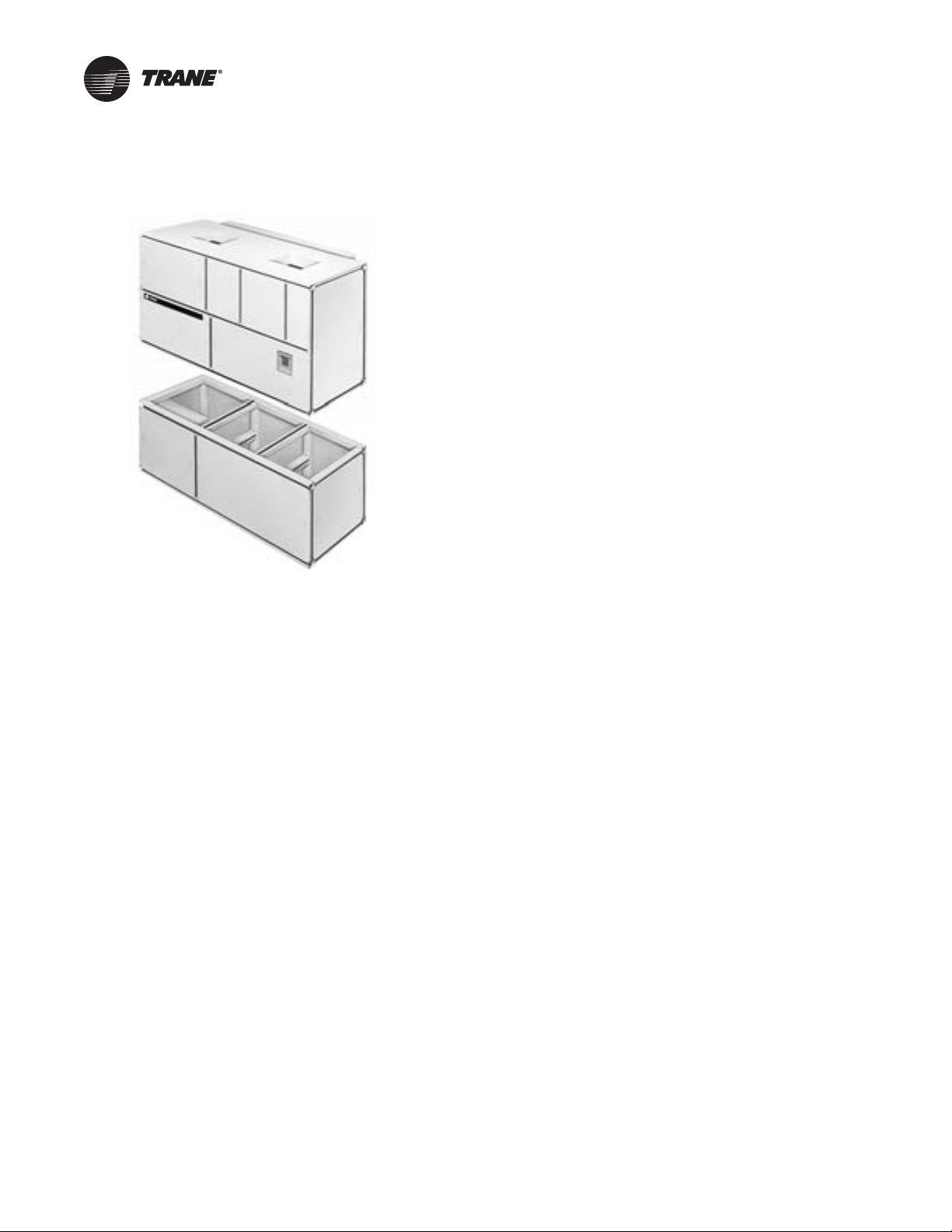
• Modular design allows the fan/coil section to “split-apart”
from the compressor section
• 35” wide base that fits through standard door openings
• Trane 3-D® Scroll compressors give reliable, efficient,
and quiet operation
• Unit mounted microprocessor control with human
interface panel
• Hinged and removable control panel door for easy access
• Waterside or airside economizer for “free cooling”
• Two-bolt connection on cleanable condenser for quick,
easy maintenance
• Waterside valve package option to enhance system
efficiency
• Sight glasses with ports for viewing unit while running
• 2-inch flat filter box inside unit casing
• Energy saving with variable frequency drive (VFD)
• Sloped drain pan for indoor air quality
This document and the information in it are the property ofTrane, and may not be used or
reproduced in whole or in part without written permission.Trane reserves the right to revise this
publication at any time, and to make changes to its content without obligation to notify any person
of such revision or change.
Trademarks
Trane and theTrane logo are trademarks of Trane in the United States and other countries. All
trademarks referenced in this document are the trademarks of their respective owners.
Revision History
PKG-PRC003U-EN (09 Jun 2014)
Updated to correct460V, 7.5HP, ODPFan motor FLAvalue, and input line current for 575V, 15HP, with
bypass.
PKG-PRC003-EN (04 Apr 2013)
Add wireless comm interface (WCI).
PKG-PRC003-EN (15 Oct 2012)
Corrected fan motor information. Updated fan FLA and LRA values in Electrical Data tables
© 2014 Trane All rights reserved PKG-PRC003U-EN
Page 3

Table of Contents
Introduction ......................................................2
Features and Benefits ..............................................5
Why consider Modular Series self-contained floor-by-floor systems? .... 6
Integrated Self-Contained Systems ................................. 9
Trane R-410A 3-D™ Scroll Compressor ............................ 11
Application Considerations .........................................12
Free Cooling Opportunities and Alternatives ........................ 14
Isolation Recommendations ...................................... 14
Condenser Water Piping ......................................... 15
Selection Procedure ...............................................17
Modular Series Self-Contained ................................... 19
Model Number Descriptions ........................................19
Self-Contained Ship-With Accessory Model Number ................. 21
Remote Air-Cooled Condenser ................................... 21
General Data .....................................................22
Performance Data ................................................25
Airside Pressure Drop ........................................... 25
Waterside Pressure Drop ........................................ 28
Water-Cooled Unit Performance .................................. 30
Air-Cooled Unit Performance ..................................... 38
Heating Performance ........................................... 41
Controls ........................................................42
Heat Module Option ............................................ 42
Generic BAS Option (GBAS) ..................................... 42
LonTalk™ Building Automation System ............................ 43
BACnet™ Building Automation System ............................ 43
Standard Control Features on IntelliPak™ Units ..................... 44
Airside Options ................................................ 49
IntelliPak™ Units - Zone Temp Control (Sequence Of Operation) ....... 49
IntelliPak™ Units - Supply Air Temp Control (Sequence Of Operation) . . 51
Zone Sensor Options ........................................... 53
Electrical Data ....................................................56
Selection Procedures ........................................... 56
Determination of Minimum Circuit Ampacity (MCA) .................. 56
PKG-PRC003U-EN 3
Page 4

Table of Contents
Dimensions and Weights ..........................................59
Variable Frequency Drive Without ByPass .......................... 69
Variable Frequency Drive With ByPass ............................. 74
Service Clearances ............................................. 78
Mechanical Specifications ..........................................79
Modular Series Self-Contained ................................... 79
IntelliPak™ Control Options ...................................... 81
Remote Air-Cooled Condenser CCRC/CIRC .......................... 86
4 PKG-PRC003U-EN
Page 5

Features and Benefits
The industry leader in self-contained systems since 1988 is now even better!Trane’s modular series
unit is easy to install, flexible, and now has the latest control technology. New modular DDC
controls with human interface (HI) panel make self-contained units easier to operate.
The modular series design fits the needs of the retrofit/renovation market.The unit easily “splits”
apart to fit into freight elevators. In addition, we can ship the compressor section separate from the
fan/coil section for field installation. Filter, economizer, and heating coil sections are all removable
for added flexibility.Also, the modular series is smallenough tofit through a standard 35-inch door
opening.
The IntelliPak™ unit’s DDC controls areTrane-designed to work withTrane equipment for optimum
efficiency. The factory installs and commissions each control component to ensure simple and
reliable operation. Also, the IntelliPak® self-contained unit has a unit mounted human interface
panel as standard and a remote option that will monitor up to four units.
Easy to install
• Passes through standard 35-inch door opening
• Removable fan/coil section from compressor section for those applications that requirethe unit
to be “split apart”
• Ship separate fan/coil section for field installation
• Removable filter, economizer and heating coil sections for added flexibility
Flexible
• Left or right hand condenser connections for field piping\Condenser piping factory manifolded
and extended to the unit exterior for a single inlet and outlet
• Economizer factory piped for either right or left hand connections and extended to the unit
exterior for a single inlet and outlet
• Free cooling with either waterside or airside economizer options
• Hot water, steam, and electric heating coil options
• Control system choices include:
• Thermostat interface for simple constant volume applications
• Direct digital controls (DDC) available on the IntelliPak self-contained, offers the most
advanced unit control for constant volume or variable air volume applications — available
with aTracer™ LCI-I, BCI-I, or generic building automation system interface.
Easy to operate
The Intellipak self-contained unit’s control design allows greater application flexibility.You can
order exactly what the job requires as options, instead of one large control package. Unit features
are distributed among multiple field replaceable printed circuit boards.
All set-up parameters are preset from the factory, requiring less startup time during installation.
In addition, IntelliPak self-contained unitshave a humaninterface panel thatdisplays unit operating
parameters and conditions in English, Spanish, or French language, making it easy to adjust
setpoints or service. It also requires less time for building maintenance personnel to learn to
interact with the unit. Human interface panel displays all of the self-contained unit’s control
parameters, such as system on/off; demand limiting type; night setback setpoints. All setpoint
adjustments are done through human interface key-pad.You can also monitor diagnostic points,
suchas sensor failures; supply airflow loss; and inoperative refrigerant circuit.Diagnostics are held
in memory, even during power loss.This allows operator/servicer to diagnose failure root cause.
PKG-PRC003U-EN 5
Page 6

Features and Benefits
Why consider Modular Series self-contained floor-by-floor systems?
Improved Cash Management
• Factory-installed and tested options reduce field labor and installation risk, while improving
system reliability
• Requires less sophisticated maintenance than built-up systems
Tenant Satisfaction
• Complete HVAC system on each floor minimizes tenant inconvenience during routine
maintenance
• Tenants can control system after hours to increase productivity and minimize expense
Low First Cost
• Reduce field labor, installation time, and cost with factory packaged controls and piping
• Reduce installed tonnage up to 20% by taking advantage of building diversity and VAV
flexibility
• Flexible air discharge arrangement matches most building configurations
Lower Installed Cost
• Single-point power connection
• Single-point water connection
• Factory commissioned and tested controls
• Factory installed options
• Internally trapped drain connection
Economical Operation
• Free cooling year-round with waterside or airside economizer
• Energy savings with floor-by-floor system since only units on floors requiring cooling need to
operate
• Significant annual energy consumption reduction compared to a central chilled water system
due to partial occupancy after-hours
• Simple heating alternatives include perimeter radiation and fan-powered VAV
• Energy savings from the integrated water valve control using pump unloading
Assured Acoustical Performance
• Flexible, horizontal discharge plenum provides smooth airflow, reducing static pressure losses
for optimum acoustical performance
• Multiple compressor design reduces acoustical levels. Scroll compressor design smooths gas
flow for quieter operation
Indoor Air Quality (IAQ) Features
• Sloped drain pan
• Stainless steel sloped drain pan option
• Internally trapped drain connection
• Double wall construction option
• Matt-faced fiberglass insulation
• High efficiency throwaway filter option
6 PKG-PRC003U-EN
Page 7

Features and Benefits
• Easily cleanable evaporator, condensers, and waterside economizers
• Filter access door allows easy removal to encourage frequent filter changing
• Airside economizer option with Traq™ damper allows direct measurement and control of
outdoor air
Enhanced Serviceability
• Self-supporting removable panels
• Quick access service panel fasteners
• Refrigerant line sight glasses in view during operation
• Easy to adjust setpoints and operating parameters using the human interface panel on
IntelliPak units.
Standard Features
• 20 through 35 ton industrial and commercial water-cooled self-contained units
• 20 through 32 ton industrial/commercial remote air-cooled self-contained units
• IntelliPak™ DDC controls or thermostat interface
• ImprovedTrane 3-D™ scroll compressor
• Constant volume (CV) or variable air volume (VAV) operation
• Low ambient compressor lockout adjustable control input
• EISA efficiency supply fan open drip proof (ODP) or totally enclosed fan cooled (TEFC) motor
options
• Emergency stop input
• Refrigeration circuits are completely factory piped and tested on water-cooled units
• Water-cooled condensers are factory piped and tested, mechanically cleanable
• Two-bolt removable condenser waterboxes for quick and easy cleaning
• Sloped drain pans to ensure complete condensate removal for IAQ
• Internally trapped drain connection with cleanout
• Internally isolated centrifugal supply fan
• Sturdy galvanized steel framework with easily removable painted exterior galvanized steel
panels
• UL listing on standard options
• Fan belts and grease lines are easily accessible
• Access panels and clearance provided to clean evaporator and waterside economizer coil fins
• Condensing pressure control on all variable water flow systems with valves
• Complete factory run–in test with power and water
Standard Control Features
• Unit mounted human interface panel with a two line x 40 character language (English, Spanish,
or French) display and a 16-function keypad that includes custom, diagnostics, and service test
mode menu keys
• Compressor lead/lag
• FROSTAT™ coil frost protection on all units
• Daytime warmup (occupied mode) and morning warmup operation
• Supply air static over pressurization protection on units with variable frequency drives (VFDs)
• Supply airflow proving
PKG-PRC003U-EN 7
Page 8

Features and Benefits
• Supply air tempering control with heating option
• Supply air heating control on VAV with hydronic heating option
• Mappable sensors and setpoint sources
• Occupied/unoccupied switching
• Timed override activation
• Programmable water purge during unoccupied mode
• High entering air temperature limit
• Low entering air temperature limit with waterside economizer or hydronic heat
Optional Features
• Trane LCI-I communication interface module: ICS interface control module
• BACnet Communications Interface Module
• Generic BAS interface
• Comparative enthalpy control
• Ventilation override with up to five external inputs
• Remote human interface controls up to four units
• Waterside modulating condensing temperature control valves include factory installed piping
• Removable cast iron headers on cleanable waterside economizer
• Refrigerant suction discharge line service (shut-off) valves
• Protective coating on unit and/or evaporator coils
• Double wall construction
• Stainless steel sloped drain pan
• Medium efficiency throwaway filters
• Through-the-door non-fused disconnect switch
• High duct temperature thermostat
• Dual electrical power connection
• CO2 reset input
• Trane’s air qualityTraq™ damper in mixing box
and control wiring
Factory Installed or Ship Separate Options
• Waterside economizer with factory installed piping and controls
• Flexible horizontal discharge plenum with or without factory cut holes, double wall perf
• Heating options include hot water, steam, and electric (field installed only)
Field Installed Accessories
• Airside economizer control with or without mixing box
• Wireless comm interface (WCI)
• Programmable sensors with or without night set back - CV and VAV
• ICS zone sensors used withTracer™ system for zone control
• Field installed module kits available to upgrade controls
• Ultra low leak dampers for 0-100% & modulating fresh air economizer
• Fully integrated variable frequency drive (VFD) control with or without optional integrated
bypass
8 PKG-PRC003U-EN
Page 9
Integrated Self-Contained Systems
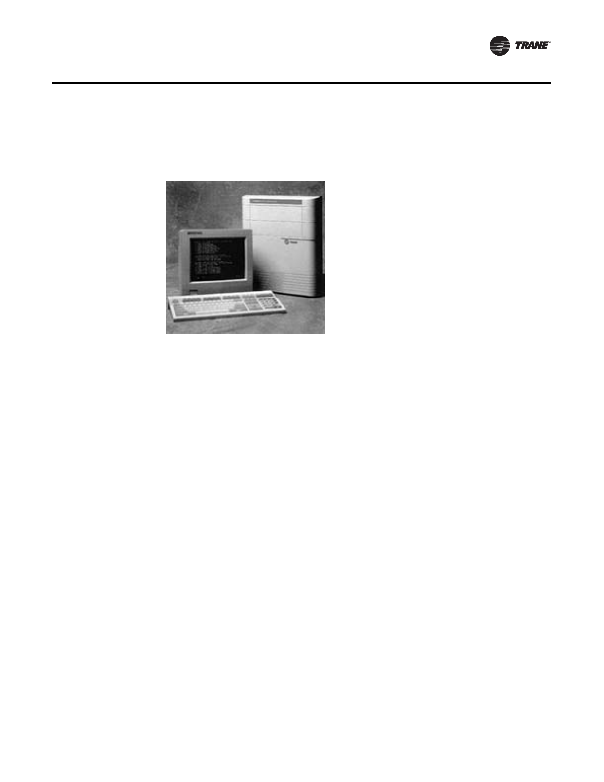
Integrated Comfort™ System (ICS)
Figure 2. You can control, monitor, and service your facility using Trane’s ICS and your PC
Features and Benefits
Trane’s Integrated Comfort™ system (ICS)
increases job control by combining IntelliPak™
Modular Series self-contained units and aTracer
building management system.This integrated
system provides total building comfort and
control. Building owners and managers not only
save energy when using ICS — they have the
ability to automate their facilities and the
convenience of a control system interface.
Simplifying The Comfort System
Trane’s designers combined new technology and
innovation to bring you more system capabilities
and flexibility. Our Integrated Comfort™ system
(ICS) with HVAC equipment is easy to use, install,
commission, and service.
Everything you need to know about your self-contained VAV system is available usingTracer
building automation products.Tracer is a software package that minimizes custom programming
requirements and allows easy system setup and control using your personal computer. Operating
data from all system components is readily available for evaluation.You can control, monitor, and
service your facility — all from your personal computer.
The IntelliPak self-contained unit, as part ofTrane ICS, provides powerful maintenance monitoring,
control, and reporting capabilities.Tracer places the self-contained unit in the appropriate
operating mode for: system on/off, night setback, demand limiting, setpoint adjustment based on
outside parameters and much more.You can monitor unit diagnostic conditions throughTracer
such as: sensor failures, loss of supply airflow, and an inoperative refrigerant circuit.
IntelliPak Modular Series Self-Contained Monitoring Points Available Using
Tracer
• Compressor on/off status
• Ventilation status
• Condenser water flow status
• Heat status
• Supply air pressure
• Supply air temperature
• Suction temperature of each circuit
• Entering economizer water temperature
• Zone temperature
• Entering condenser water temperature
• Supply air temperature reset signal
• Morning warmup sensor temperature
• Entering air temperature
PKG-PRC003U-EN 9
Page 10

Features and Benefits
Tracer Control Points for IntelliPak Modular Series Self-Contained Units
• Cooling and heating setpoints
• VAV discharge air temperature setpoints
• Supply air pressure setpoint
• Cooling and heating enable/disable
• Air economizer enable/disable
• Air-side economizer minimum position
• Unit priority shutdown
Interoperability with BACnet
TheTraneTracer SC BACnet Control Interface (BCI) for IntelliPak self-contained offers a building
automation control systemwith outstanding interoperabilitybenefits. BACnet, whichis an industry
standard, is an open, secure and reliable network communication protocol for controls, created by
American Society of Heating, refrigerating and Air-Conditioning Engineers, Inc. (ASHRAE)
Interoperability allows application or project engineers to specify the best products of a given type,
rather than one individual supplier's entire system. It reduces product training and installation
costs by standardizing communications across products. Interoperable systems allow building
managers to monitor and control IntelliPak equipment withTracer SC controls or a 3rd party
building automation system. It enables integration with many different building controls such as
access/intrusion monitoring, lighting, fire and smoke devices, energy management, and a wide
variety of sensors (temperature, pressure, humidity, occupancy, CO2 and air velocity).
Commissioning, control, efficiency, and information…it simply all adds up to one reliable
source…Trane.
Trane Wireless Comm Interface (WCI)
TheTrane®Wireless Comm Interface (WCI) is the perfect alternative toTrane’s BACnet™ wired
communication links (for example, Comm links between aTracer™ SC and aTracer™ UC400).
Minimizing communication wire used between terminal products, zone sensors, and system
controllers has substantial benefits. Installation time and associated risks are reduced. Projects are
completed with fewer disruptions. Future re-configurations, expansions, and upgrades are easier
and more cost effective.
10 PKG-PRC003U-EN
Page 11
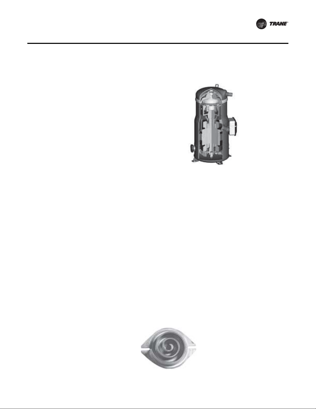
Trane R-410A 3-D™ Scroll Compressor
The R-410ATrane 3-D™ Scroll provides
important reliability and efficiency benefits
inherent in its design.The 3-D™ Scroll allows
the orbiting scrolls to touch in all three
dimensions, forming a completely enclosed
compression chamberwhich leads toincreased
efficiency. In addition, the orbiting scrolls only
touch with enough force to create a seal,
eliminating wear between the scroll involutes.
The fixed and orbiting scrolls are made of high
strength cast iron which results in less thermal
distortion and minimal leakage. In addition,
improved part isolation provides reduced
compressor sound levelscompared to previous
designs.
Features listed below optimize the compressor design and performance:
• Optimized scroll profile
• Heat shield protection to reduce heat transfer between discharge and suction gas
• Improved sealing between high side and low side
Additional features are incorporated in the compressor design for greater reliability:
• Patented design motor cap for improved motor cooling
• Improved bearing alignment
• Improved resistance to dry start-up
• Oil sight glass for evaluating proper oil levels
Features and Benefits
LowTorque Variation
The 3-D™ Scroll has a very smooth compression cycle, imposing very little stresson the motor and
resulting in greater reliability. Low torque variation reduces noise and vibration.
Suction Gas Cooled Motor
Compessor motor efficiency and reliability is further optimized with the latest scroll design.The
patented motor cap directs suction gas over the motor, resulting in cooler motor temperatures for
longer life and better efficiency.
Proven Design through Testing and Research
The new R-410A 3-D™ Scroll compressor is the next generation of reliable Trane 3-D™ Scroll
compressors provided byTrane, the leader in scroll compressor technology
.
Figure 3. One of two matched scroll plates - the distiguishing feature of the scroll compressor
PKG-PRC003U-EN 11
Page 12
Application Considerations
Self-Contained Acoustical Recommendations
Successful acoustical results are dependent on manysystem design factors. Following are general
acoustical recommendations. For more information, or if there is concern about a particular
installation, contact a professional acoustical consultant.
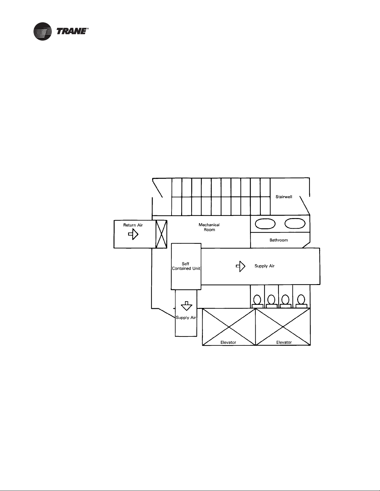
Location and Orientation of the Mechanical Equipment Room
Locate the equipment room adjacent to stairwells, utility rooms, electrical closets, and rest rooms
if possible. See Figure 4, p. 12.This minimizes the acoustic effects and risk of workmanship or
installation errors. Place the discharge and return air ductwork over these less acoustically
sensitive areas, using vertical orhorizontal fresh air shafts. Consult code requirements for fresh air
and smoke purge constraints.
Figure 4. Equipment room location and orientation
Return Air Ductwork
Duct the return air into the mechanical equipment room. Connect ductwork to the unit if local code
dictates.The return air ductwork must have an elbow inside the equipment room. Extend the
ductwork from the elbow far enough to block the “line of sight” to the exterior of the equipment
room. Use aminimum ductwork lengthof 15 feetto the equipmentroom exterior. Line theduct with
two-inch, three-pound density insulation. Use multiple, small return ducts for better acoustical
performance to the occupied space.
Supply Air Ductwork
Insulate the supplyair duct with two-inch, three-pound densityinsulation. Extend thislining at least
15 feet out from the equipment room wall, keeping the duct aspect ratio as small as possible.
Minimize large flat panels since they transmit sound. In addition, small aspect ratios will minimize
potential “oil canning” of the duct due to flow turbulence.
12 PKG-PRC003U-EN
Page 13
Application Considerations
The flexible horizontal discharge plenum option helps avoid complicated ductwork transitions.
Ductwork turning vanes typically improve pressure drop but degrade acoustical performance.
Recommended Maximum Air Velocities
The maximum recommended velocity for the discharge air duct is 2,000 fpm. The maximum
recommended velocity for the return air duct is 1,000 fpm. Limit air velocities below these
operating points to minimize the risk of flow turbulence that causes regenerated noise. Using
round supply duct and static regain allows maximum discharge air velocities up to 3,000 fpm.
Lining round supply duct also substantially lowers frequency noise attenuation. However, flow
regenerated noise potential increases dramatically at air velocities over 3000 fpm.
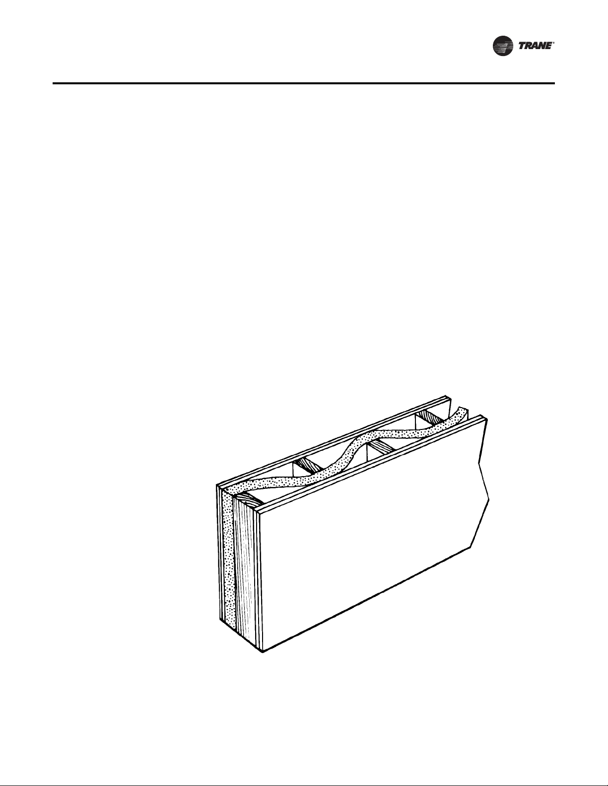
Equipment Room Construction Options
The preferred equipment room wall construction is concrete block. If this is not feasible then a
double stud offset wall is suggested. See Figure 5, p. 13.This removes physical contact that would
transmit sound through the equipment room wall to the occupied space. Interweave fiberglass
insulation between the wall studs. Use two layers of sheetrock on each side of the wall.
Workmanship details are critical to acoustical performance. Seal all wall and floor penetrations by
the ductwork, water piping, and equipment room access doors with a flexible material such as
caulk and/or gasketing to stop noise and air leaks.
Locate the equipment room door away from acoustically sensitive areas like conference rooms.
The door should swing out of the equipment room, if possible, so that the low pressure in the
equipment room pulls the door in to help maintain a tight seal.
Figure 5. Double stud offset wall with interwoven insulation
PKG-PRC003U-EN 13
Page 14

Application Considerations
Equipment Options
The flexible horizontal discharge plenum allows multiple tested outlet options.This minimizes the
risk of acoustic and/or pressure drop problems by avoiding complex transitions close to the fan
discharge.
Static PressureVersus Acoustics
Design the system to minimize the total static pressure required from the self-contained unit fan.
Typically a change in static pressure of only 0.5 inches can reduce NC level by approximately 2 or
3 in the occupied space.
Free Cooling Opportunities and Alternatives
Free cooling is available with either airside or waterside economizers.The advantages and
disadvantages of each type are listed as follows:
Waterside Economizer
The waterside economizer substantially reduces the compressor energy requirements because it
uses the cooling water before it enters the condensers. Additional equipment room space is not
required since the coils are contained within the overall unit dimensions.
Disadvantages include higher airside pressure drop and a higher head on condenser water pumps.
The coils may be mechanically cleanable (optional) for ease in maintenance versus expensive and
difficult chemical cleaning methods.
Airside Economizer
The airside economizer substantially reduces compressor, cooling tower, and condenser water
pump energy requirements using outside air for free cooling. It also reduces tower make up water
needs and related water treatment.
Disadvantages include building requirements that locate the mechanical room and self-contained
unit toward an exterior wall to minimize ductwork, building barometric control, or additional air
shafts. Also, airside economizers require additional mechanical room space.
Isolation Recommendations
Unit
The Modular Series unit is internally isolated so that external isolation is not required. Consult a
vibration specialist before using external isolation.TheTrane Company does not recommend
double isolation. If isolation external to the unit is preferred, remove internal isolators.
Ductwork
Design duct connections to the unit using a flexible material. Consult local codes for approved
flexible duct material to prevent fire hazard potential.
Piping Connections
Rubber isolator connectors are recommended for condenser piping to prevent vibration
transmission to or from thebuilding plumbing.The Modular Seriesself-contained unit is internally
isolated and does not require additional isolation. However, do not forget to design proper system
vibration isolation to prevent vibration transmission from the building plumbing to the unit. Also
be sure that the drain line is properly isolated.
14 PKG-PRC003U-EN
Page 15

Condenser Water Piping
Piping Location and Arrangement
Provide at least 24 inches of clearance between the piping and the unit for service. Place the risers
away from the side of the unit if possible. Be sure to allow sufficient space for valves and unions
between the piping andthe self-contained unit. Layout condenser piping in reverse returns to help
balance the system.This is accomplished by equalizing the supply and return pipe length. Multistory buildings may use a direct return system with balancing valves at each floor. Install all heat
exchangers and most cooling tower piping below the sump operating water level to prevent
overflow during unit and/or system shut down.
Recommended Pump Location
Pump location is preferred downstream of the cooling tower and upstream of the self-contained
unit.This provides smoother and more stable unit operation.
When the tower and pump are both roof mounted, be sure to provide the necessary net positive
suction head pressure to prevent cavitation. Raise the tower or submerge the pump in a sump to
provide positive suction.To prevent an on-line pump failure, use a standby pump to avoid a
complete system shutdown. Use several partial capacity pumps or variable speed pumps. Review
the economics of these alternate pumping options.
Strainers and WaterTreatment
Water strainers are required at the unit inlet to eliminate potential unit damage from dirty water.
Specify a water basket strainer to avoid an incorrect application of a stream strainer. Untreated or
poorly treated water may result in equipment damage. Consult a water treatment specialist for
treatment recommendations.
Application Considerations
Isolation Valves
Install isolation valves at each unit before the strainer and after the condenser.This allows periodic
servicing of the unit or strainer while allowing other units in the system to remain in operation.
Pressure Gauges
Install pressure gauges on the inlet and outlet of the self-contained unit. Select the gauge’s scale
so that the unit design operating point is approximately mid-scale.
Thermometers
Install thermometers on the condenser water inlet and outlet linesto each unit for system analysis.
Trane recommends using athermometer temperature range of 40to 140°F, using a2°F temperature
increment.
Drains
The unit condensate drain is internally trapped to offset the pressure differential that exists during
fan operation. Install a trapped drain in the low point of the mechanical equipment room floor to
collect water from cleaning operations.
Condensing Pressure Control
(Water-Cooled condensers)
Often cold condensing water applications between 54°F and 35°F require a condensing pressure
control valve. Any unit with variable-flow waterside valves can modulate water flow to maintain
a user defined condensing temperature. However, to utilize this feature, the building water system
must be capable of operating at reduced water flow rates through the self-contained units. It is
imperative to install variable volume pumps or an external bypass in the water distributionsystem.
PKG-PRC003U-EN 15
Page 16

Application Considerations
Waterside Economizer Flow Control
Units equipped with waterside economizer control valves can be set up for variable or constant
water flow. Use constant water flow setup on water systems that are not capable of unloading
water supply to the unit.The economizer and condenser valves will operate in complement to one
another to provide continuous water flow.
Use variable water flow setup with water flow systems that can take advantage of pump unloading
for energy savings. Since non-cooling operation restricts water flow during part load economizing
or condensing temperature control, it is imperative to install variable volume pumpsor an external
bypass in the water distribution system.
Airflow Limitations
The minimum recommended airflow for proper VAV system staging and temperature control is
35% of nominal design airflow. However, using VAV boxes at the appropriate minimum settings
will prevent the self-contained unit fromoperating in a surge condition at airflows below thispoint.
Continuous operation in a surge condition can cause fan failure. See Table 1, p. 22 for minimum
airflow conditions.
Modular Series self-contained units use fixed pitch sheaves. Adjust air balancing by obtaining
alternate fixed pitch sheave selections from the localTrane sales office.
Waterflow Limitations
Use 3 gpm/ton for optimum unit capacity and efficiency. Use 2.5 or 2 gpm/ton to reduce pump
energy, cooling tower and piping costs. However, these reduced waterflows may impact unit
capacity and efficiency by one or two percent. Consult the general data section for unit specific
waterflow ranges.
Air Cooled Condenser Location
Unobstructed condenser airflow is essential to maintaining capacity and operating efficiency.
When determining unitplacement, give carefulconsideration to assure sufficient airflow across the
condenser coils. Avoid these two detrimental conditions:warm air recirculation and coil starvation.
Both warm air recirculation and coil starvation cause reductions in unit efficiency and capacity
because of the higher head pressure associated with them. In more severe cases, nuisance unit
shutdowns will result from excessive head pressures.
Clearances
Ensure vertical condenser air discharge is unobstructed. While it is difficult to predict the degree
of warm air recirculation, a unit installed with a ceiling or other obstruction above itwill experience
a capacity reduction that will reduce the maximum ambient operation. Nuisance high head
pressure tripouts may also occur.
The coil inlet must also be unobstructed. A unit installed closer than the minimum recommended
distance to a wall or other vertical riser will experience a combination of coil starvation and warm
air recirculation.This may result in capacityand efficiency reductions, as well as possible excessive
head pressures. Reference the service clearance section for recommended lateral distances.
Ambient Limitations
Standard ambient control allows operation down to 45°F with cycling of condenser fans. Units with
the low ambient option are capable of starting and operating in ambient temperatures down to 0°F.
Optional low ambient units use a condenser fan damper arrangement that controls condenser
capacity by modulating damper airflow in response to saturated condenser temperature.
Maximum cataloged ambient temperature operation of a standard condenser is 115°F. Operation
at design ambient above 115°F can result in excessive head pressures.
16 PKG-PRC003U-EN
Page 17

Selection Procedure
Following is a sample selection for a standard applied water-cooled self-contained at particular
operating conditions. UseTrane Official Product Selection System,TOPSS™, for making all final
selections or contact your localTrane sales office.
Unit Capacities
1. Determine entering air temperature dry bulb and wet bulb and entering water temperature.
2. Refer to performance Table 7, p . 30 through Table 19, p. 41 to find gross total and sensible
capacity that best meets capacity requirements.
3. Apply the cfm correction factors from the capacity correction factor Table 6, p. 29 to determine
gross total and gross sensible capacities at desired cfm.
4. Multiply condenser water deltaT by the total capacity cfm correction factor to determine new
condenser water deltaT.
5. Using design cfm, determine static air pressure drops for accessories from the air pressure
drop
Figure 6, p. 25 through Figure 11 , p . 27. Add accessory static pressure drops to external
supply and return static air pressure drops. Use the total air pressure drop to determine rpm
and brake horsepower requirements from the appropriate fan curve. Note: The fan curves
include refrigerant coil and internal cabinet static loses.
6. Calculate supply fan motor heat by using the following equation:
Fan motor heat (MBh) = 2.8 x fan motor brake horsepower
7. Determinenet total capacity andnet sensible capacity bysubtracting fan motor heatfrom gross
total capacity and gross sensible capacity.
8. Refer to theTrane psychometric chart to determine leaving air temperatures.
Waterside Economizer Capacity
1. After determining that the unit will meet the required mechanical cooling capacity, determine
the waterside economizer capacity by referring to the appropriate two-row (low capacity) or
four-row (high capacity) waterside economizer capacity tables for the unit size.
2. Determine entering air temperature dry bulb and wet bulb, condenser water flow (gpm), and
economizer entering water temperature.
3. Refer to the appropriate waterside economizer table to find gross total and sensible capacity
and the leaving water temperature.
4. Apply the cfm correction factor for the waterside economizer from the appropriate table to
determine the gross total and sensible capacities at the desired cfm.
5. Multiply the condenser water deltaT by the total capacity cfm correction factor to determine
the new deltaT.
6. Calculate supply fan motor heat by using the following equation:
Fan motor heat (MBh) = 2.8 x fan motor brake horsepower
7. Determine net total and sensible capacity by subtracting fan motor heat from gross total and
sensible capacity.
8. Refer to theTrane psychometric chart to determine leaving air temperatures.
Selection Example
Design Conditions
Total gross capacity required = 368.7 MBh = 31Tons
Total sensible capacity required = 259 MBh
Entering air temperature = 80/67°F
Entering water temperature = 85
gpm = 105
PKG-PRC003U-EN 17
Page 18

Selection Procedure
Selection Procedure
Airflow = 14200 cfm at 2.5-inch duct static pressure
Unit to include:
Constant Volume
Waterside economizer
Medium velocity throwaway filters
Unit Selection
Tentatively select a 35 ton unit. Refer to Table 13, p. 36 to obtain gross total and sensible unit
capacities, and gpm at the design conditions:
Total capacity = 370 MBh
Sensible capacity = 282 MBh
LWT = 95.4°F
Since the design cfm is greater than the nominal cfm, adjust the capacities and condenser water
deltaT to reflect the higher cfm:
design cfm/nominal cfm 14,240/14,000 + 3% from nom. Cfm
Refer to Table 6, p. 29 to obtain the capacity correction factors for +3% of nominal cfm:
Cooling capacity multiplier = 1.005
Sensible capacity multiplier = 1.014
Multiply the capacities by the correction factors:
370 MBh x 1.005 = 371.85 MBh
282 MBh x 1.014 = 285.95 MBh
The SCWG 35 meets the total and sensible design requirements.
Multiply the deltaT of 10.4°F, by the cooling capacity correction factor of 1.005 to obtain new delta
T of 10.45 and add this to the entering water temperature to obtain the actual leaving water
temperature, 95.45°F.
Determine static air pressure drops through the accessories at the design cfm by referring to
Figure 6, p. 25 through Figure 11, p. 27.
4-row waterside economizer = 0.55 in.Medium velocity filters = 0.41 in.Add this to the 2.5-inchduct
static pressure fora total external staticpressure of 3.46 inches. Refer tothe fan curvewith Constant
Volume, Figure 18, p. 37 to determine approximate brake horsepower and fan rpm:
Fan brake horsepower = 25 bhp
Fan rpm = 1850 rpm
Determine net capacities by subtracting fan motor heat from gross capacities:
2.8 x 25 bhp = 70.0 MBh
Net total capacity = 371.85 MBh - 70.0 MBh = 301.85 MBh
Net sensible capacity = 285.95 MBh - 70.0 MBh = 215.95 MBh
Determine waterside economizer (full coil) capacity by referring to Table 13, p. 36. Use entering air
of 80/67°F and entering water temperature of 55°F at 105 gpm. The table provides a gross total
capacity of 263.6 MBh and gross sensible capacity of 263.6 MBh and 60.0°F leaving water
temperature at nominal cfm.
Determine gross capacities at design cfm by applying the cfm correction factors from waterside
economizer from Table 6, p. 29. Use the following correction factors:
263.6 MBh x 1.005 = 264.92 MBh
263.6 MBh x 1.014 = 267.29 MBh
Apply the cooling correction factor to water deltaT to determine new delta T of 5.03°F.
Determine net capacities by subtracting fan motor heat for net total capacity of 194.92MBh andnet
sensible capacities of 197.29 MBh.
18 PKG-PRC003U-EN
Page 19

Model Number Descriptions
Modular Series SelfContained
Digit 1 - Unit Model
S = self contained
Digit 2 - Unit Type
C = commercial
I = industrial
Digit 3 - Condenser Medium
W = water-cooled
R = remote air-cooled
Digit4-Development Sequence
G = modular series
Digit 5 - Refrigerant Circuit
Configuration
U = independent, R-410A refrigerant
Digits 6, 7 - Unit Nominal
Capacity
20 = 20Tons (water or air cooled)
25 = 25Tons (water or air cooled)
30 = 30Tons (water cooled only)
32 = 32Tons (air cooled only)
35 = 35Tons (water cooled only)
Digit 8 - Unit Voltage
6 = 200 volt/60 hz/3 ph
4 = 460 volt/60 hz/3 ph
5 = 575 volt/60 hz/3 ph
Digit 9 - Air Volume/Temp
Control
2 = I-Pak &VFD & supply air temp ctrl
3 = I-Pak &VFD w/ bypass & supply
air temp ctrl
4 = I-Pak w/o vol. ctrl, w/ zone temp
cool
5 = I-Pak w/o vol. ctrl, w/ zone temp
heat/cool
6 = I-Pak w/o vol. ctrl, w/ supply air
temp ctrl
8 = thermostat interface
Digits 10, 11 - Design Sequence
** = Factory Assigned
Digit 12 - Unit Construction
A = vertical discharge
B = vertical discharge with double
wall
C = horizontal discharge
D = horizontal discharge w/ double
wall
E = vertical discharge, ship separate
F = vert. dis. w/ double wall, ship sep.
G = horizontal discharge, ship
separate
H = horiz. dis. w/ double wall, ship
sep.
Digit 13 - Plenum Type
B = std plenum w/ factory cut holes
C = low plenum w/ factory cut holes
E = std plenum w/ field cut holes
F = low plenum w/ field cut holes
H = std plenum double wall (perf)
w/ field cut holes
J = low plenum double wall (perf)
w/ field cut holes
L = std. plenum w/factory cut holes,
ship separate
M = low plenum w/ factory cut holes,
ship separate
P = std plenum w/ field cut holes, ship
separate
R = low plenum w/ field cut holes,
ship separate
U = std plenum double wall (perf) w/
field cut holes, ship separate
V = low plenum double wall (perf) w/
field cut holes, ship separate
0 = without plenum
Digit 14 - Motor Type
2 = ODP motor
3 = TEFC motor
Digits 15, 16 - Motor HP
05 = 5 hp
07 = 7.5 hp
10 = 10 hp
15 = 15 hp
20 = 20 hp
25 = 25 hp
Digits 17, 18, 19 - Fan RPM
085 = 850 rpm
090 = 900 rpm
095 = 950 rpm
100 = 1000 rpm
105 = 1050 rpm
110 = 11 0 0 r p m
115 = 1150 rpm
120 = 120 0 rpm
125 = 1250 rpm
130 = 130 0 rpm
135 = 1350 rpm
140 = 1400 rpm
145 = 1450 rpm
150 = 150 0 rpm
155 = 1550 rpm
160 = 160 0 rpm
165 = 1650 rpm
170 = 170 0 rpm
175 = 1750 rpm
180 = 180 0 rpm
185 = 1850 rpm
Digit 20 - Heating Type
A = steam coil, LH
B = hot water coil, LH
C = electric heat, 1 stage
F = hydronic heat ctrl interface
G = elec. heat ctrl interface,1 stage
K = steam coil ship separate, LH
L = hot water coil ship separate, LH
M = steam coil, RH
N = hot water coil, RH
P = steam coil ship separate, RH
R = hot water coil ship separate, RH
T = hi-cap. hot water coil, LH
U = hi-cap hot water coil, LH, ship sep
V = hi-cap hot water coil, RH
W = hi-cap hot water coil, RH, ship sep
0 = none
Digit 21 - Unit Isolators
A = isopads
B = spring isolators
0 = none
Digit 22 - Unit Finish
1 = paint - slate gray
2 = protective coating
3 = protective coating w/ finish coat
Digit 23
0 = none
Digit 24 - Unit Connection
1 = disconnect switch
2 = terminal block
3 = dual point power
Digit 25 - Industrial Options
A = protective coated evaporator coil
B = silver solder
C = stainless steel screws
D = A and B
E = A and C
F = B and C
G = A, B and C
0 = none
Digit 26 - Drain Pan Type
A = galvanized sloped
B = stainless steel sloped
Digit 27 - Waterside Economizer
A = mechanical clean full capacity
(4-row)
B = mechanical clean low capacity
(2-row)
C = chemical clean full capacity
(4-row)
D = chemical clean low capacity
(2-row)
E = mechanical clean full capacity
(4-row) ship separate
F = mechanical clean low capacity
(2-row) ship separate
G = chemical clean full capacity
(4-row) ship separate
H = chemical clean low capacity
(2-row) ship separate
0 = none
PKG-PRC003U-EN 19
Page 20

Model Number Descriptions
Digit 28 - Ventilation Control
B = airside econ w/Traq™ damper
(top O/A inlet)
C = airside econ w/ standard
dampers (top O/A inlet)
E = airside econ w/ Traq™ damper
and comparative enthalpy
(top O/A)
F = airside econ w/ std dampers and
comparative enthalpy (top O/A)
H = none/ventilation for 2-position
control interface
J = airside economizer interface
K = airside economizer interface w/
comparative enthalpy
0 = None
Digit 29 - Water Piping
A = RH condenser connection
B = LH condenser connection
C = RH basic piping
D = LH basic piping
E = RH intermediate piping
F = LH intermediate piping
J = RH basic w/ flow switch
K = LH basic w/ flow switch
L = RH intermediate w/ flow switch
M = LH intermediate w/ flow switch
0 = none
Digit 30 - Condenser Tube Type
A = standard condenser tubes
B = 90/10 CuNi condenser tubes
0 = none
Digit 31 - Compressor Service
Valves
1 = with service valves
0 = none
Digit 32 - Miscellaneous System
Control
1 = timeclock
2 = interface for remote HI (IPCB)
3 = dirty filter switch
4 = 1 and 2
5 = 1 and 3
6 = 2 and 3
7 = 1, 2, and 3
0 = none
Digit 33 - Control Interface
Options
A = Generic BAS Module; 0-5VDC
(GBAS)
B = Ventilation Override Module
(VOM)
D = Remote Human Interface (RHI)
G = GBAS &VOM
H = GBAS & RHI
J = VOM & RHI
M = GBAS & VOM & RHI
N = BACnet Communications
Interface (BCI)
P = BCI and GBAS
Q = BCI and VOM
R = BCI and RHI
T = BCI and GBAS andVOM
U = BCI and GBAS and RHI
V = BCI and VOM and RHI
W = BCI and GBAS andVOM and RHI
0 = None
1 = LonTalk Comm5 Interface (LCI)
2 = LCI and GBAS
3 = LCI and VOM
4 = LCI and RHI
5 = LCI and GBAS andVOM
6 = LCI and GBAS and RHI
7 = LCI and VOM and RHI
8 = LCI and GBAS andVOM and RHI
Digit 34 - Agency
T = UL agency listing
0 = none
Digit 35 - Filter Type
1 = 2-inch construction throwaway
2 = 2-inch med eff. throwaway
Digit 36 - Miscellaneous Control
Option
A = low entering air temp. protect
device (LEATPD)
B = high duct temp t-stat
C = plenum high static switch
D = kit for heat mode output (w/t’stat)
E = A and B
F = A and C
G = B and C
H = A, B, and C
0 = None
20 PKG-PRC003U-EN
Page 21

Model Number Descriptions
Self-Contained Ship-
With Accessory
Model Number
Digit1-Parts/Accessories
P = parts/accessories
Digit 2 - Unit Model
S = self-contained
Digit 3 - Shipment
W = with unit
Digit4-Development Sequence
F = signature series
G = modular series
Digit5-Sensors and Other
Accessories
S = sensors
Digit6-Sensors and
Thermostats (Field Installed)
A = BAYSENS077 - zone temp only
(CV and VAV)
B = BAYSENS073- zone temp with
timed override button (CV and
VAV)
C = BAYSENS074 - zone temp with
timed override button, setpoint
dial (CV and VAV)
E = BAYSENS108 - CV zone sensor
-dual setpoint, man/auto
changeover
F = BAYSENS110 - CV zone sensor-
dual setpoint, man/auto
changeover w, indicastor lights
G = BAYSENS119 - CV/VAV program-
mable night setback Sensor
H = BAYSENS021 -VAV zone sensor
with indicator lights
K = BAYSTAT150 2H/2C ProgTstat w/
BAYSTAT077 Remote Sensor
L = outside air temperature sensor kit
M = outside air humidity sensor kit
N = BAYSTAT155 3H/2CTstat
P = BAYSTAT150 2H/2C
ProgrammableTstat
0 = none
Digit 7 - Mixed Air Temperature
Protection Kit (Field Installed)
1 = mixed air temperature protection
kit
0 = none
Digit 8 - Carbon Dioxide Sensor
(Field Installed)
1 = carbon dioxide sensor kit
0 = none
Digit9-Future Option
0 = none
Digits 10, 11 - Design Sequence
** = Factory Assigned
Remote Air-Cooled Condenser
Digit 1 - Unit Model
C = Condenser
Digit 2 - Unit Type
C = Commercial
I = Industrial
Digit 3 - Condenser Medium
R = Remote
Digit4-Development Sequence
C=C
Digits 5, 6, 7 - Nominal Capacity
020 = 20Tons
029 = 29Tons
032 = 32Tons
Digit 8 - Unit Voltage
4 = 460 Volt/60 Hz/3 ph
5 = 575 Volt/60 Hz/3 ph
6 = 200 Volt/60 Hz/3 ph
Digit 9 - Control Option
0 = No Low Ambient, I-Pak
A = No Low Ambient, T-stat
B = Low Ambient, I-Pak
C = Low Ambient, T-stat
Digits 10, 11 - Design Sequence
** = Factory Assigned
Digit 12 - Unit Finish
1 = Paint - Slate Gray
2 = Protective Coating
3 = Protective Coating with
Finish Coat
4 = Unpainted Unit
Digit 13 - Coil Options
A = Non-Coated Aluminum
C = Protective Coated Aluminum
Digit 14 - Unit Isolators
0 = None
A = Spring Isolators
B = Isopads
Digit 15 - Panels
0 = None
1 = Louvered Panels
Digit 16 - Agency
0 = None
T = UL Listing
PKG-PRC003U-EN 21
Page 22
General Data
Table 1. SCWG/SIWG/SCRG/SIRG general data
Water-Cooled Units Air-Cooled Units
Unit Size 20 25 30 35 20 25 32
Compressor Data
Quantity 2 2 1/1 2 2 1/1 2
Nominal Ton/Comp 10 10 10/15 15 10 10/15 15
Circuits 2 2 2 2 2 2 2
Evaporator Coil Data
Rows 2 4 4 4 3 4 4
Sq. Ft. 22.5 25.0 25.0 25.0 25.0 25.0 25.0
FPF 144 144 144 144 144 144 144
Condenser Data
Minimum GPM w/o Econ 36 36 46 54 - - Minimum GPM w/ Econ 41 41 60 65 - - Maximum GPM 80 80 102 119 - - -
Evaporator Fan Data
Quantity 2 2 2 2 2 2 2
Size (Dia. x width - inches) 12 5/8"x8" 12 5/8"x9" 12 5/8"x11" 12 5/8 x11" 12 5/8"x8" 12 5/8"x9" 12 5/8"x11"
Minimum HP 5 5 5 5 5 5 5
Maximum HP 20 25 25 25 20 25 25
Minimum Design CFM 6350 7250 7250 7250 7250 7250 7250
Maximum Design CFM 8500 10,625 12,750 14,875 8500 10,625 13600
R-410A Refrigerant Data
EER 14.0 14.3 14.1 14.0 10.0 10.1 10.4
IEER (CV) 14.1 14.8 15.4 15.6 10.8 11.8 11.9
IEER (VFD) 17.1 18.1 18.2 17.7 13.4 13.3 13.8
Refrigerant Charge - lb (kg)
Circuit A 19.0 (8.6) 24.0 (10.9) 24.5 (11.1) 23.0 (10.4) See Note 3 See Note 3 See Note 3
Circuit B 19.0 (8.6) 24.0 (10.4) 23.0 (10.4) 23.0 (10.4) See Note 3 See Note 3 See Note 3
Capacity Steps - % 100/53/0 100/53/0 100/65/42/6 100/53/0
Filter Data
Quantity 4 4 4 4 4 4 4
Size (inches) 16x25x2 16x25x2 16x25x2 16x25x2 16x25x2 16x25x2 16x25x2
Quantity 4 4 4 4 4 4 4
Size (inches) 20x25x2 20x25x2 20x25x2 20x25x2 20x25x2 20x25x2 20x25x2
CCRC/CIRC Condenser
Match
Notes:
1. Compressors are Trane 3D™scroll.
2. EER and IEER are rated in accordance to the AHRI Standard 340/360-2010. Based on 80/67°F (26.7/19.4°C) to the evaporator coil, nominal airflow
and 85-95°F (29.4-35°C) condenser water or 95° F (35° C) ambient.
3. All units operate with R-410A. Water Cooled units ship with full operating charge. Air-cooled Units ship with dry nitrogen charge. Field refrigerant
system charge required. Refer to Table 3, p. 23 for amounts required.
4. Maximum cfm limits are set to prevent moisture carryover on the evaporator coil.
5. Minimum cfm limits are set to ensure stable thermal expansion valve operation at low load conditions.
6. Filter sizes are for units without hot water or steam heating coils
- - - - 20 29 32
22 PKG-PRC003U-EN
Page 23

General Data
Table 2. SCWG/SIWG/SCRG/SIRG self-contained heating coil
Filter Data for Heating Coil
Quantity 4
Size (inches) 20x18x2
Size (mm) (508x457x51)
Quantity 8
Size (inches) 20x20x2
Size (mm) (508x508x51)
Coil Data Type Rows No. - Size (in) No. - Size (mm) fpf
Steam Coil NS 1 2 - 24 x 58 2 - 609.6x1473.2 42
Hot Water Coil, std. cap 5W 1 1 - 48 x 62 1 - 1219 x 1575 80
Hot Water Coil, hi-cap. 5W 2 1 - 48 x 62 1 - 1219 x 1575 108
Notes:
1. Hot water and steam heating coils have Prima-Flo® fins and do not have turbulators.
2. For coil capacities, use TOPSS™ (Trane Official Product Selection Program).
Table 3. SCRG/SIRG self-contained and CCRC/CIRC remote air-cooled condenser, refrigerant data
SCRG/SIRG & CCRC/CIRC Unit Size 20/20 25/29 32/32
No. of Refrigerant Circuits 222
Operating Charge - lbs R-410A 36.5/36.5 48.5/36 46/46
Operating Charge - kg R-410A 16.6/16.6 22/16.3 20.9/20.9
Cond. Storage Cap. - lbs R-410A 37/37 51/37 51/51
Cond. Storage Cap. - kg R-410A 16.8/16.8 23.1/16.8 23.1/23.1
Notes:
1. Refrigerant charges are listed as circuit 1/circuit 2 and provide only an estimate. Final charge requires sound field charging practice.
2. Operating charge estimate includes the air-cooled self-contained, remote air-cooled condenser, and 25 feet of interconnecting refrigerant piping.
3. At conditions of 95°F (35°C), condenser storage capacity is 95% full.
4. To determine the correct amount of refrigerant needed for a particular application, reference the Trane Reciprocating Refrigeration Manual.
Table 4. Waterside economizer coil physical data
Model Unit Size Type Rows FPF height (in) length (in)
SCXG 20, 25, 30 & 35 Chemically Cleanable 2 108 50 72
SCXG 20, 25, 30 & 35 Mechanically Cleanable 2 108 50 72
SCXG 20, 25, 30 & 35 Chemically Cleanable 4 108 50 72
SCXG 20, 25, 30 & 35 Mechanically Cleanable 4 108 50 72
PKG-PRC003U-EN 23
Page 24

General Data
Table 5. CCRC/CIRC remote air-cooled condenser general data
Unit Size 20 29 32
Condenser Fan Data
Number/Type/Drive 4/Prop/Direct 4/Prop/Direct 4/Prop/Direct
Size (inches) 26 26 26
HP ea. 111
Nominal Cfm 18,800 21,200 32,000
Condenser Coil Data
Circuit 1 Size (in.) 1/46x71 1/46x71 1/64x71
Circuit 2 No./Size (in.) 1/46x71 1/64x71 1/64x71
Face Area (sq. ft.) 45.4 54.2 63.1
Rows/fpf 4/144 4/144 4/144
Ambient Temperature Operating Range
Standard Ambient (°F) 50-115 50-115 50-115
Low Ambient Option (°F) 0-115 0-115 0-115
24 PKG-PRC003U-EN
Page 25
Performance Data
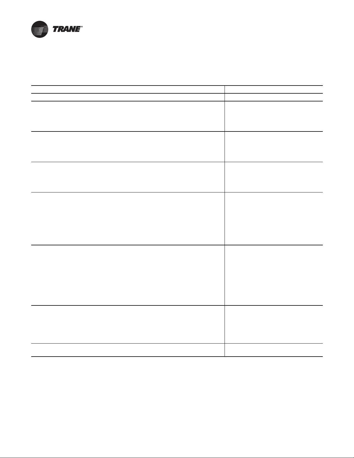
Airside Pressure Drop
Figure 6. Filter airside pressure drop
Note: In Figure 6, p. 25, lines 1 and 3 are for the SXWG 20 ton only. Lines 2 and 4 are for all air-cooled units and all SXWG
25-35 tons.
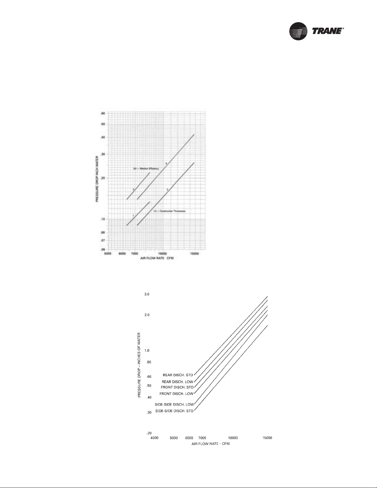
Figure 7. Horizontal discharge plenum airside pressure drop
PKG-PRC003U-EN 25
Page 26
Performance Data
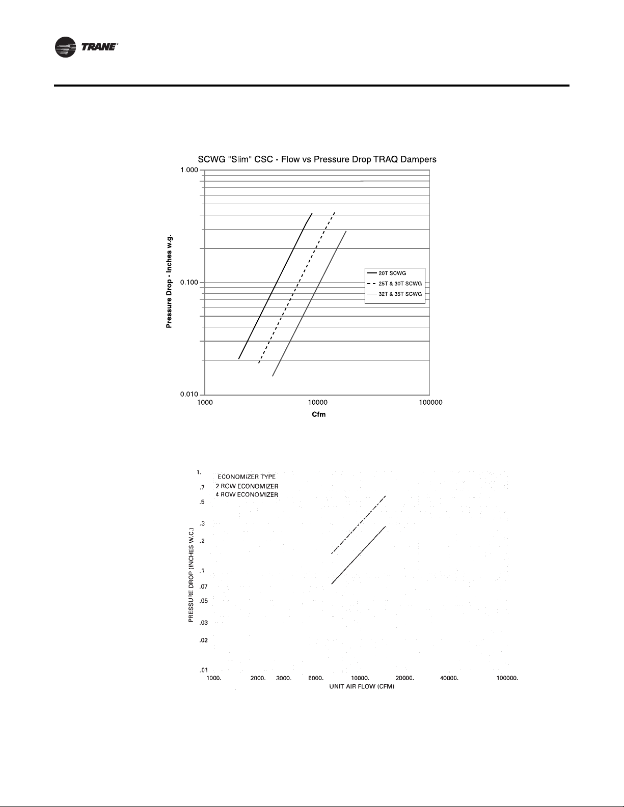
Figure 8. Traq™ damper airside pressure drop
Figure 9. Waterside economizer airside pressure drop
26 PKG-PRC003U-EN
Page 27
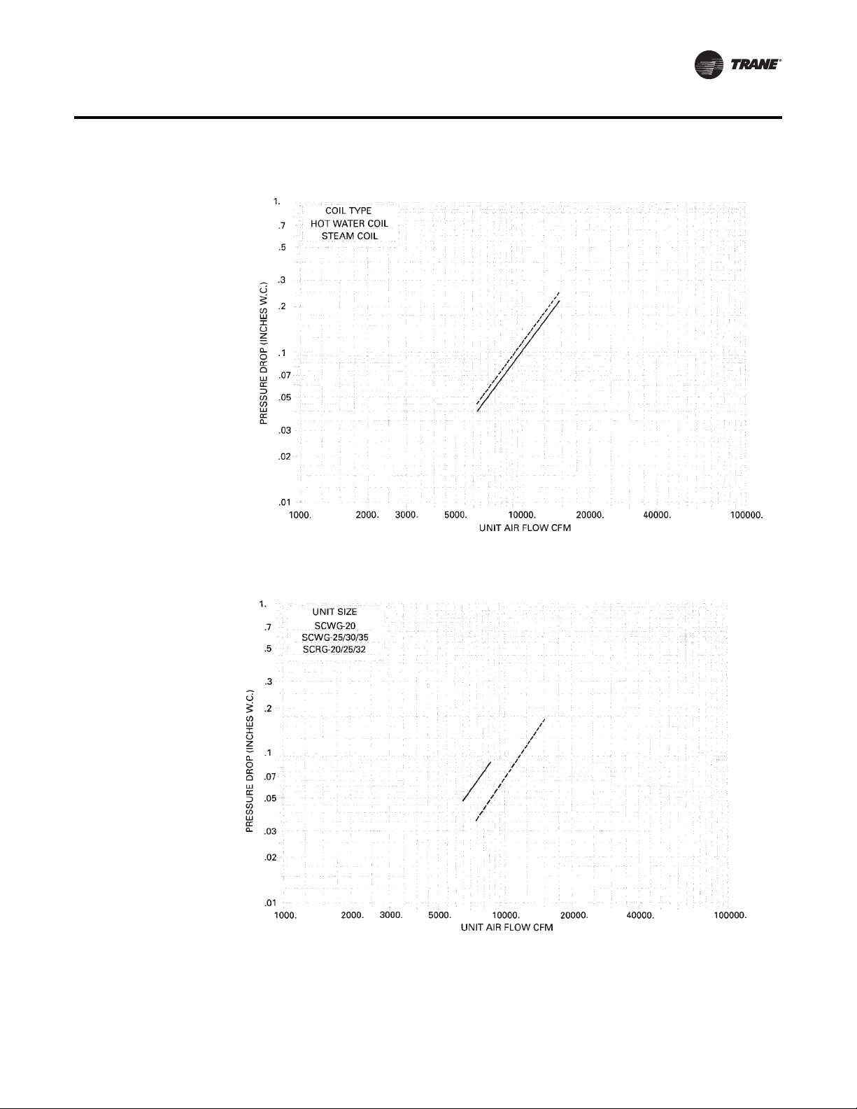
Figure 10. Steam coil airside pressure drop
Performance Data
Figure 11. Airside economizer airside pressure drop
PKG-PRC003U-EN 27
Page 28

Performance Data
Waterside Pressure Drop
Figure 12. Waterside economizer waterside pressure drop
Figure 13. Unit without piping water pressure drop
28 PKG-PRC003U-EN
Page 29

Figure 14. Unit with piping waterside pressure drop
Performance Data
Note: “Primary” refers to the side where the static pressure drop was measured. This value must be added to the unit external
static pressure for proper fan horsepower determination.
Table 6. CFM capacity correction table
DX cooling
Waterside economizer
CFM compared to rated
quantity
-20% 0.970 0.910
-10% 0.985 0.955
Std 1.000 1.000
+3% 1.005 1.014
+6% 1.009 1.027
-20% 0.970 0.910
-10% 0.985 0.955
Std 1.000 1.000
+3% 1.005 1.014
+6% 1.009 1.027
cooling capacity
multiplier
sensible capacity
multiplier
PKG-PRC003U-EN 29
Page 30

Performance Data
Water-Cooled Unit Performance
20-ton Water-Cooled
Table 7. SCWG/SIWG 20 economizer full capacity - 8,000 cfm
full capacity coil low capacity coil
45°F 55°F 45°F 55°F
EDB EWB flow total sensible LWT total sensible LWT total sensible LWT total sensible LWT
°F °F gpm MBh MBh °F MBh MBh °F MBh MBh °F MBh MBh °F
50 215.3 192.8 53.6 135.9 135.9 60.4 142.6 142.6 50.7 96.5 96.5 58.9
62
60 225.9 197.3 52.5 139.7 139.7 59.6 152.1 149.8 50.1 99.9 99.9 58.3
70 233.9 200.7 51.7 142.3 142.3 59.1 157.5 152.0 49.5 102.4 102.4 57.9
50 270.4 163.0 55.8 158.5 121.2 61.3 179.3 118.3 52.2 104.8 91.6 59.2
75
67
60 289.4 170.5 54.6 167.9 124.5 60.6 192.5 123.3 51.4 110.9 93.7 58.7
70 303.9 176.4 53.7 175.4 127.2 60.0 202.3 127.0 50.8 115.8 95.4 58.3
50 344.7 135.8 58.8 224.9 94.1 64.0 229.0 92.7 54.1 149.8 66.3 61.0
72
60 370.7 145.4 57.3 242.1 99.9 63.1 246.2 98.7 53.2 160.6 69.8 60.3
70 390.2 152.8 56.1 255.5 104.4 62.3 259.1 103.3 52.4 169.1 72.5 59.8
50 235.6 235.6 54.4 169.8 169.8 61.8 166.4 166.4 51.6 120.6 120.6 59.8
62
60 242.7 242.7 53.1 174.5 174.5 60.8 172.9 172.9 50.7 124.8 124.8 59.2
70 251.2 250.5 52.2 177.8 177.8 60.1 177.5 177.5 50.1 127.9 127.9 58.7
50 277.2 208.3 56.1 175.5 169.9 62.0 182.9 155.4 52.3 120.9 120.9 59.8
80
67
60 294.0 215.0 54.8 182.7 172.5 61.1 194.4 159.7 51.5 125.1 125.1 59.2
70 306.9 220.2 53.7 188.2 174.5 60.4 203.3 163.1 50.8 128.2 128.2 58.7
50 344.0 179.0 58.7 226.2 137.7 64.0 228.6 128.4 54.1 149.5 102.1 61.0
72
60 369.8 188.7 57.3 242.2 143.1 63.1 245.6 134.4 53.2 160.1 105.5 60.3
70 389.2 196.1 56.1 255.0 147.4 62.3 258.5 139.0 52.4 168.5 108.2 59.8
50 269.3 269.3 55.7 203.7 203.7 63.1 190.3 190.3 52.6 144.8 144.8 60.8
62
60 277.2 277.2 54.2 209.2 209.2 62.0 197.6 197.6 51.6 149.8 149.8 60.0
70 282.7 282.7 53.1 213.2 213.2 61.1 202.8 202.8 50.8 153.5 153.5 59.4
50 290.3 256.0 56.6 204.4 204.4 63.2 190.7 190.7 52.6 145.1 145.1 60.8
85
67
60 304.9 261.8 55.1 210.0 210.0 62.0 204.4 199.1 51.8 150.1 150.1 60.0
70 316.0 266.3 54.0 214.0 214.0 61.1 211.8 201.9 51.0 153.8 153.8 59.4
50 347.4 223.1 58.9 235.8 183.7 64.4 228.8 164.3 54.1 155.9 140.0 61.2
72
60 371.1 232.0 57.3 249.6 188.4 63.3 245.2 170.1 53.1 164.6 142.8 60.5
70 389.3 238.9 56.1 260.5 192.1 62.4 258.0 174.6 52.3 171.6 145.1 59.9
30 PKG-PRC003U-EN
Page 31

Performance Data
Table 8. SCWG/SIWG 20 gross cooling capacity - 8,000 cfm, 60 gpm
entering water temp
entering air 75°F 85°F 95°F
EDB EWB total sensible total sensible total sensible
°F °F MBh MBh LWT MBh MBh LWT MBh MBh LWT
62 269 197 84.8 259 192 94.7 249 187 104.6
75
80
85
Figure 15. Fan performance for CV or with VFD
67 294 162 85.6 283 158 95.5 271 153 105.3
72 321 127 86.5 309 122 96.3 296 117 106.1
62 270 230 84.8 261 226 94.7 250 220 104.6
67 294 197 85.6 284 192 95.5 272 187 105.4
72 321 161 86.5 309 157 96.3 296 151 106.1
62 270 270 84.8 262 262 94.8 253 253 104.7
67 295 230 85.6 285 225 95.5 273 219 105.4
72 322 195 86.5 310 191 96.3 297 186 106.1
Note: Fan curves include refrigerant coil and internal cabinet static losses. T o determine static pressure to use with these curves,
add filter; economizer; flexible horizontal discharge plenum; and heat pressure drops to external duct static pressure.
PKG-PRC003U-EN 31
Page 32

Performance Data
25-ton Water-Cooled
Table 9. SCWG/SIWG 25 economizer - 10,000 cfm
full capacity coil low capacity coil
45°F 55°F 45°F 55°F
EDB EWB flow total sensible LWT total sensible LWT total sensible LWT total sensible LWT
°F °F gpm MBh MBh °F MBh MBh °F MBh MBh °F MBh MBh °F
105.1
110.2
111.8
103.7
106.3
107.3
71.6
76.1
77.7
131.5
137.8
139.8
131.7
138.0
140.1
113.9
118.3
119.9
157.9
165.4
167.9
158.2
165.7
168.2
159.1
162.7
164.0
75
80
85
62
67
72
62
67
72
62
67
72
63
75
80
63
75
80
63
75
80
63
75
80
63
75
80
63
75
80
63
75
80
63
75
80
63
75
80
236.9
251.4
256.4
292.6
317.7
326.5
372.7
406.4
418.1
266.7
277.9
281.6
301.5
405.5
331.8
371.9
405.5
417.2
305.0
223.0
321.8
319.3
339.0
345.8
376.5
407.4
418.3
225.2
231.2
233.3
184.8
194.5
197.9
149.0
161.0
165.2
266.7
277.9
281.6
240.4
213.6
252.2
201.4
213.6
217.9
305.0
223.0
321.8
299.4
307.1
309.8
255.5
266.7
270.7
52.5
51.7
51.4
54.3
53.5
53.2
56.8
55.8
55.5
53.5
52.4
52.0
54.6
55.8
53.3
56.8
55.8
55.4
54.7
50.9
53.0
55.1
54.0
53.7
57.0
55.9
55.5
154.9
160.9
162.8
174.1
186.1
90.4
245.1
267.0
274.6
193.7
201.1
203.5
194.3
267.2
209.4
246.6
267.2
274.4
232.5
168.9
244.1
233.2
242.0
244.9
259.0
276.8
283.1
154.9
160.9
162.8
141.4
145.6
147.2
105.5
112.7
115.2
193.7
201.1
203.5
194.3
165.4
206.2
158.7
165.4
167.8
232.5
168.9
244.1
233.2
242.0
244.9
215.2
221.1
223.2
59.9
59.3
59.1
60.5
60.0
60.0
62.8
62.1
61.9
61.2
60.4
60.1
61.2
62.1
60.2
62.8
62.1
61.9
62.4
59.5
61.1
62.4
61.5
61.1
63.2
62.4
62.1
153.6
162.0
164.7
184.6
202.1
208.2
235.1
257.9
265.8
179.4
189.1
192.3
190.1
205.3
210.6
234.7
257.4
265.3
205.3
216.3
219.9
205.7
216.7
220.3
235.6
257.2
264.8
153.6
162.0
164.7
129.7
136.2
138.4
97.5
105.2
107.9
179.4
189.1
192.3
173.9
179.5
181.5
139.7
147.4
150.1
205.3
216.3
219.9
205.7
216.7
220.3
182.3
189.6
192.2
49.9
49.3
49.1
50.9
50.4
50.2
52.5
51.9
51.6
50.7
50.0
49.8
51.0
50.5
50.3
52.5
51.9
51.6
51.5
50.8
50.5
51.5
50.8
50.5
52.5
51.9
51.6
105.1
110.2
111.8
110.6
118.3
121.1
155.8
169.9
174.9
131.5
137.8
139.8
131.7
138.0
140.1
155.6
169.4
174.3
157.9
165.4
167.9
158.2
165.7
168.2
164.6
175.9
179.9
58.3
57.9
57.8
58.5
58.2
58.0
59.9
59.5
59.4
59.2
58.7
58.5
59.2
58.7
58.5
59.9
59.5
59.4
60.0
59.4
59.2
60.0
59.4
59.2
60.2
59.7
59.5
32 PKG-PRC003U-EN
Page 33

Performance Data
Table 10. SCWG/SIWG 25 gross cooling capacity - 10,000 cfm, 75 gpm
entering water temp
entering air 75°F 85°F 95°F
EDB EWB total sensible total sensible total sensible
°F °F MBh MBh LWT MBh MBh LWT MBh MBh LWT
62 297 245 84.1 286 240 94.0 272 233 103.8
75
80
85
Figure 16. Fan performance for CV or with VFD
67 324 195 84.9 311 190 94.7 296 184 104.4
72 352 142 85.6 337 136 95.4 320 130 105.1
62 298 295 84.2 287 287 94.0 273 273 103.8
67 325 244 84.9 312 239 94.7 297 232 104.5
72 353 193 85.6 338 187 95.4 322 181 105.2
62 317 317 84.7 307 307 94.6 295 295 104.4
67 326 294 84.9 313 288 94.7 298 281 104.5
72 354 243 85.7 339 238 95.4 323 232 105.2
Note: Fan curves include refrigerant coil and internal cabinet static losses. T o determine static pressure to use with these curves,
add filter; economizer; flexible horizontal discharge; and heat pressure drops to external duct static pressure.
PKG-PRC003U-EN 33
Page 34

Performance Data
30-ton Water-Cooled
Table 11. SCWG/SIWG 30 economizer capacity - 12,000 cfm
full capacity coil low capacity coil
45°F 55°F 45°F 55°F
EDB EWB flow total sensible LWT total sensible LWT total sensible LWT total sensible LWT
°F °F gpm MBh MBh °F MBh MBh °F MBh MBh °F MBh MBh °F
120.4
125.9
129.7
119.6
122.4
124.6
82.2
86.9
90.5
150.7
157.4
162.2
150.9
157.7
162.5
131.3
135.9
139.5
180.9
188.9
194.7
181.2
189.3
195.0
183.6
187.3
190.3
75
80
85
62
67
72
62
67
72
62
67
72
75
90
105
75
90
105
75
90
105
75
90
105
75
90
105
75
90
105
75
90
105
75
90
105
75
90
105
274.7
290.5
302.5
338.7
366.4
387.7
431.4
468.5
496.8
310.4
323.0
331.8
348.8
373.4
392.4
430.5
467.4
495.7
354.9
369.1
379.1
369.9
391.3
407.7
434.9
469.2
495.8
264.2
270.7
275.7
215.8
226.4
234.8
173.0
186.3
196.5
310.4
323.0
331.8
281.5
291.0
298.4
235.0
248.2
258.6
354.9
369.1
379.1
351.3
359.6
366.1
298.6
311.0
320.7
52.3
51.5
50.8
52.3
51.5
50.8
54.0
53.1
52.4
56.5
55.4
54.5
54.3
53.3
52.5
56.5
55.4
54.4
54.5
53.2
52.2
54.9
53.7
52.8
56.6
55.4
54.4
179.9
186.6
191.3
200.7
213.7
224.1
282.5
306.4
324.8
224.9
233.2
239.1
225.5
233.9
245.7
283.9
306.4
324.1
270.0
279.8
286.8
270.7
280.7
287.7
298.3
317.6
332.8
179.9
186.6
191.3
165.6
170.1
173.8
122.4
130.2
136.3
224.9
233.2
239.1
225.5
233.9
243.4
185.2
192.6
198.4
270.0
279.8
286.8
270.7
280.7
287.7
252.1
258.4
263.5
59.8
59.2
58.6
60.4
59.8
59.3
62.5
61.8
61.2
61.0
60.2
59.6
61.0
60.2
59.7
62.6
61.8
61.2
62.2
61.2
60.5
62.2
61.2
60.5
63.0
62.1
61.3
176.8
185.7
192.1
212.2
230.7
244.8
270.2
294.3
312.6
206.5
216.7
224.1
218.2
234.2
246.7
269.8
293.7
312.0
236.2
247.9
256.2
236.6
248.3
256.7
270.4
293.3
311.4
176.8
185.7
192.1
149.9
156.7
161.9
112.2
120.4
126.7
206.5
216.7
224.1
201.0
206.9
211.5
161.2
169.4
175.7
236.2
247.9
256.2
236.6
248.3
256.7
210.5
218.3
224.5
49.7
49.1
48.7
50.7
50.1
49.7
52.2
51.5
51.0
50.5
49.8
49.3
50.8
50.2
49.7
52.2
51.5
50.9
51.3
50.5
49.9
51.3
50.5
49.9
52.2
51.5
50.9
120.4
125.9
129.7
126.3
134.3
140.8
177.9
192.8
204.3
150.7
157.4
162.2
150.9
157.7
162.5
177.6
192.2
203.6
180.9
188.9
194.7
181.2
189.3
195.0
187.8
199.6
208.8
58.2
57.8
57.5
58.4
58.0
57.7
59.7
59.3
58.9
59.0
58.5
58.1
59.0
58.5
58.1
59.7
59.3
58.9
59.8
59.2
58.7
59.8
59.2
58.7
60.0
59.4
59.0
34 PKG-PRC003U-EN
Page 35

Performance Data
Table 12. SCWG/SIWG 30 gross cooling capacity - 12,000 cfm, 87 gpm
Entering Water Temp
Entering Air 75°F 85°F 95°F
EDB EWB Total Sensible Total Sensible Total Sensible
°F °F MBh MBh LWT MBh MBh LWT MBh MBh LWT
62 360 294 84.6 347 288 94.4 330 280 104.3
75
80
85
Figure 17. Fan performance for CV or with VFD
67 392 234 85.3 376 228 95.2 359 221 104.9
72 425 171 86.1 408 165 95.9 388 158 105.6
62 362 353 84.6 348 344 94.5 332 332 104.3
67 393 293 85.4 377 286 95.2 360 278 105.0
72 426 231 86.1 409 225 95.9 390 218 105.7
62 382 382 85.1 370 370 95.0 356 356 104.9
67 394 351 85.4 379 344 95.2 361 336 105.0
72 428 291 86.2 410 285 96.0 391 278 105.7
Note: Fan curves include refrigerant coil and internal cabinet static losses. T o determine static pressure used with these curves,
add filter; economizer, flexible horizontal discharge; and heat pressure drops to external duct static pressure.
PKG-PRC003U-EN 35
Page 36

Performance Data
35-ton Water-Cooled
Table 13. SCWG/SIWG 35 economizer capacity - 14,000 cfm
full capacity coil low capacity coil
45°F 55°F 45°F 55°F
EDB EWB flow total sensible LWT total sensible LWT total sensible LWT total sensible LWT
°F °F gpm MBh MBh °F MBh MBh °F MBh MBh °F MBh MBh °F
134.5
139.8
143.1
134.4
137.0
138.8
92.0
96.5
99.5
254.4
262.9
268.1
255.0
263.6
268.9
210.6
217.9
222.9
168.3
174.8
178.9
168.6
175.1
179.2
147.4
151.8
154.8
75
80
85
6288105
119
6788105
119
7288105
119
6288105
119
6788105
119
7288105
119
6288105
119
6788105
119
7288105
119
310.4
325.9
335.9
382.4
410.1
428.2
487.2
524.2
548.1
351.7
364.5
372.3
393.4
417.8
433.8
486.1
523.0
546.8
402.1
416.6
425.3
417.5
438.6
452.3
491.0
524.5
547.1
301.6
308.0
312.2
245.5
256.1
263.1
195.8
209.0
217.7
351.7
364.5
372.3
320.9
330.2
336.4
267.1
280.2
288.9
402.1
416.6
425.3
401.0
409.2
414.6
340.2
352.2
360.4
52.1
51.2
50.7
53.7
52.8
52.2
56.1
55.0
54.2
53.0
51.9
51.3
53.9
53.0
52.3
56.1
55.0
54.2
54.1
52.9
52.2
54.5
53.4
52.6
56.2
55.0
54.2
203.5
210.3
214.5
225.6
238.4
247.2
317.8
341.7
357.5
254.4
262.9
268.1
255.0
263.6
268.9
319.1
341.5
356.7
305.3
315.4
321.6
306.1
316.2
322.5
335.2
354.3
367.2
203.5
210.3
214.5
188.6
193.1
196.2
138.5
146.3
151.5
254.4
262.9
268.1
255.0
263.6
268.9
210.6
217.9
222.9
305.3
315.4
321.6
306.1
316.2
322.5
287.4
293.6
297.9
59.6
59.0
58.6
60.1
59.5
59.2
62.2
61.5
61.0
60.8
60.0
59.5
60.8
60.0
59.5
62.3
61.5
61.0
61.9
61.0
60.4
62.0
61.0
60.4
62.6
61.8
61.2
198.2
206.8
212.1
237.9
255.7
267.1
302.8
325.9
340.8
231.4
241.4
247.5
244.0
259.4
269.5
302.2
325.3
340.2
264.7
276.0
282.9
265.1
276.4
283.4
302.6
324.7
339.5
198.2
206.8
212.1
168.6
175.1
179.4
125.9
133.7
138.9
231.4
241.4
247.5
226.1
231.7
235.5
181.3
189.1
194.2
264.7
276.0
282.9
265.1
276.4
283.4
236.8
244.3
249.3
48.6
50.4
49.9
51.9
51.2
50.7
49.6
49.2
50.6
49.5
51.9
51.2
51.0
50.3
49.8
50.3
49.8
51.9
50.7
58.1
57.7
58.2
57.8
57.6
59.1
58.7
58.8
134.5
139.8
143.1
140.6
148.2
153.5
198.2
212.6
222.0
254.4
262.9
268.1
255.0
263.6
268.9
319.1
341.5
356.7
168.3
174.8
178.9
168.6
175.1
179.2
197.8
211.9
221.3
58.1
57.7
57.4
57.8
57.6
59.5
58.7
58.8
58.3
58.8
58.3
58.0
59.0
58.7
59.6
58.6
59.6
59.0
59.8
59.2
58.8
59.6
59.0
58.6
59.8
59.2
58.8
36 PKG-PRC003U-EN
Page 37

Performance Data
Table 14. SCWG/SIWG 35 gross cooling capacity - 14,000 cfm, 105 gpm
entering water temp
entering air 75°F 85°F 95°F
EDB EWB total sensible total sensible total sensible
°F °F MBh MBh LWT MBh MBh LWT MBh MBh LWT
62 430 348 84.4 413 340 94.2 395 331 104.1
75
80
85
Figure 18. Fan performance for CV or with VFD
67 467 277 85.1 449 270 94.9 428 262 104.7
72 506 204 85.8 486 196 95.6 463 188 105.4
62 431 416 84.4 415 408 94.2 396 396 104.1
67 468 345 85.1 450 338 94.9 429 329 104.7
72 507 273 85.8 487 266 95.6 464 258 105.4
62 454 454 84.8 439 439 94.7 423 423 104.6
67 469 413 85.1 451 405 95.0 431 396 104.8
72 508 343 85.9 488 336 95.7 466 327 105.4
Note: Fan curves include refrigerant coil and internal cabinet static losses. T o determine static pressure used with these curves,
add filter; economizer; flexible horizontal discharge; and heat pressure drops to external duct static pressure.
PKG-PRC003U-EN 37
Page 38

Performance Data
Air-Cooled Unit Performance
20-ton Air-Cooled
Table 15. SCRG/SIRG 20 gross cooling capacity, - 8,000 CFM
Ambient 75 85 95 105 115
EDB EWB
70
75
80
85
62 295.2 182.5 284.0 177.3 271.1 171.4 256.5 164.8 240.7 157.8
67 324.1 141.0 311.4 135.9 296.8 129.7 280.5 123.0 263.0 116.0
62 295.7 223.2 284.6 217.8 271.8 211.5 257.3 204.5 241.7 197.0
67 324.5 182.2 312.0 176.9 297.6 170.9 281.4 164.2 264.2 157.2
72 355.3 140.1 341.1 134.9 324.9 128.7 306.9 122.1 287.7 115.2
62 296.8 263.1 285.7 257.6 272.9 251.3 258.4 244.2 242.8 236.6
67 324.7 223.2 312.3 217.7 298.0 211.3 282.0 204.2 265.0 196.7
72 355.6 181.0 341.5 175.6 325.4 169.5 307.6 162.9 288.7 155.9
62 301.8 301.8 292.7 292.7 282.1 282.1 269.9 269.9 256.7 256.6
67 326.0 262.7 313.6 257.0 299.3 250.6 283.3 243.5 266.2 235.9
72 356.4 221.8 342.3 216.4 326.3 210.2 308.6 203.5 289.8 196.5
total
MBH
sensible
MBH
total
MBH
sensible
MBH
total
MBH
sensible
MBH
total
MBH
sensible
MBH
total
MBH
sensible
MBH
Figure 19. Fan performance for CV or with VFD
Note: Fan curves include refrigerant coil and internal cabinet static losses. T o determine unit’ s total static pressure add filter,
economizer, flexible horizontal discharge, and heat pressure drops to external duct static pressure.
38 PKG-PRC003U-EN
Page 39

25-ton Air-Cooled
Table 16. SCRG/SIRG 25 gross cooling capacity, - 10,000 CFM
Ambient 75 85 95 105 115
EDB EWB
70
75
80
85
62 352.4 222.1 338.2 215.7 321.9 208.1 304.3 199.5 285.0 190.6
67 386.7 169.1 370.7 162.7 352.5 155.5 332.4 147.4 311.0 139.0
62 354.2 272.1 340.3 265.2 324.3 257.4 306.5 248.8 287.5 239.6
67 386.6 220.9 370.6 214.2 352.4 206.8 332.3 198.6 310.9 190.2
72 422.5 167.4 404.6 160.9 384.3 153.7 362.2 145.6 339.0 137.5
62 355.6 322.1 341.6 315.2 325.6 307.3 307.8 298.6 288.8 285.4
67 387.6 271.2 371.9 264.2 354.2 256.3 334.6 247.6 313.9 238.4
72 422.4 218.8 404.5 212.1 384.3 204.6 362.1 196.5 339.0 188.1
62 365.3 365.3 353.6 353.6 339.9 339.9 324.6 324.6 308.0 308.0
67 389.1 320.7 373.5 313.6 355.7 305.6 336.1 296.8 315.4 287.6
72 422.3 269.6 405.0 262.4 385.0 254.5 363.8 245.5 341.4 236.5
total
MBH
sensible
MBH
total
MBH
sensible
MBH
total
MBH
sensible
MBH
total
MBH
sensible
MBH
Performance Data
total
MBH
sensible
MBH
Figure 20. Fan performance for CV or with VFD
Note: Fan curves include refrigerant coil and internal cabinet static losses. T o determine unit’ s total static pressure add filter,
economizer, flexible horizontal discharge, and heat pressure drops to external duct static pressure.
PKG-PRC003U-EN 39
Page 40

Performance Data
32-ton Air-Cooled
Table 17. SCRG/SIRG 32 gross cooling capacity, - 12,800 CFM
Ambient 75 85 95 105 115
EDB EWB
70
75
80
85
62 423.1 270.4 407.2 262.8 388.6 254.2 368.2 244.3 345.8 233.6
67 464.0 204.4 445.9 197.0 425.2 188.7 402.0 179.4 376.9 169.6
62 425.5 332.1 409.6 324.4 391.3 315.5 370.7 305.6 348.4 294.8
67 463.8 268.4 445.8 261.0 425.1 252.5 401.9 243.2 376.8 233.3
72 506.5 202.2 486.4 194.7 463.4 186.3 437.9 177.1 410.6 167.4
62 427.1 394.3 411.2 386.5 392.9 377.5 372.3 367.5 349.9 349.9
67 465.2 330.8 447.5 323.0 427.2 314.0 404.6 304.0 380.2 293.3
72 506.4 265.6 486.2 258.1 463.3 249.6 437.8 240.4 410.5 230.6
62 442.3 442.3 428.8 428.8 413.0 413.0 395.1 395.1 375.4 375.4
67 467.0 392.4 449.3 384.4 429.0 375.3 406.4 365.2 382.0 354.4
72 506.6 328.6 487.1 320.4 464.6 311.4 439.7 301.4 410.4 293.5
total
MBH
sensible
MBH
total
MBH
sensible
MBH
total
MBH
sensible
MBH
total
MBH
sensible
MBH
total
MBH
sensible
MBH
Figure 21. Fan performance for CV or with VFD
Note: Fan curves include refrigerant coil and internal cabinet static losses. T o determine unit’ s total static pressure add filter,
economizer, flexible horizontal discharge, and heat pressure drops to external duct static pressure.
40 PKG-PRC003U-EN
Page 41

Heating Performance
Table 18. Steam heating capacity
unit airflow capacity LAT capacity LAT capacity LAT
size cfm MBh °F MBh °F MBh °F
20 tons 8000 278.6 92.1 293.9 93.9 315.5 96.4
25 tons 10000 318.2 89.3 335.7 91.0 360.5 93.2
30 tons 12000 353.3 87.2 372.7 88.6 400.3 90.8
32 tons 12800 366.2 86.4 386.4 87.8 414.9 89.9
35 tons 14000 384.6 85.3 405.8 86.7 435.8 88.7
Note: Based on 60°F EAT
Table 19. Electric heating capacity
Unit Size Unit Size Heat Air Flow Capacity LAT
SCWG SCRG kW CFM MBH
20 20 16 8000 54.64 66.32
25 25 20 10000 68.30 66.32
30 N/A 24 12000 81.96 66.32
N/A 32 26 12800 88.79 66.42
35 N/A 28 14000 95.62 66.32
Notes:
1. Based on 60°F EAT.
2. For unit capacities at different conditions than those listed, use TOPSS (Trane Official Product Selection Program).
3. Air temperature rise = kW x 3413 / (CFM x 1.085).
Performance Data
2 psi 5 psi 10 psi
PKG-PRC003U-EN 41
Page 42

Controls
Modular DDC controls with human interface(HI) panel make self-contained units more flexible and
easier to operate.
Controls areTrane-designed to work withTrane equipment for optimum efficiency.The factory
installs and commissions each control component to ensure simple and reliable operation.
Furthermore, the DDC control’s modular design allows greater application flexibility using up to
twelve different modules, dependent upon unit options.You can order exactly what the job
requires as options, instead of one large control package. And since unit features are distributed
among multiple printed circuit boards, field replacement is easy.
Depending upon unit options, IntelliPak units can operate as:
1. stand-alone
2. interface withTrane’sTracer™ building management system
3. interface with a generic (non-Trane) building management system.
Available input and outputs are listed below by module.
RTM Module (on all units)
Binary inputs
• Emergency stop
• External auto/stop
• Unoccupied/occupied
• Dirty filter
• VAV changeover with hydronic heat
Binary outputs
• VAV box drive max (VAV units only)
• CV Unoccupied mode indicator (CV units only)
• Alarm
• Fan run request
• Water pump request (water-cooled only)
Analog input
• Airside economizer damper minimum position
Analog output
• Outside air damper actuator
Heat Module Option
• Analog output
Generic BAS Option (GBAS)
Binary inputs
• Demand limit contacts
Binary outputs
• Dirty filter relay
42 PKG-PRC003U-EN
Page 43

• Refrigeration fail relay
• Heat fail relay
• Supply fan fail relay
• Active diagnostics
Analog inputs
• Occupied zone cooling setpoint
• Occupied zone heating setpoint
• Unoccupied zone cooling setpoint
• Unoccupied zone heating setpoint or minimum outside air flow setpoint
• Supply air cooling setpoint
• Supply air heating setpoint
• Supply air static pressure setpoint Comparative Enthalpy Option (ECEM)
Analog inputs
• Return air temperature
• Return air humidity Ventilation Override Module Option (VOM)
Binary inputs
• VOM mode A, unit off
• VOM mode B, pressurize
• VOM mode C, exhaust
• VOM mode D, purge
• VOM mode E, purge w/duct pressure control
Controls
Binary output
• V.O. relay
LonTalk™ Building Automation System
The LonTalk Communication Interface for IntelliPak self-contained (LCI-I) controller expands
communications from the unit UCM network to aTraneTracer Summit or a 3rd party building
automation system, utilizing LonTalk, and allows external setpoint and configuration adjustment
and monitoring of status and diagnostics.The LCI-I utilizes an FTT-10A FreeTopology transceiver,
which supports nonpolarity sensitive, free topology wiring, which allows the system installer to
utilize star, bus, and loop architectures.This controller worksin standalone mode, peer-to-peer with
one or more other units, or when connected to aTraneTracer Summit or a 3rd party building
automation system that supports LonTalk.
BACnet™ Building Automation System
The BACnet Communication Interface for IntelliPak self-contained (BCI-I) controller expands
communications from the unit UCM network toTracer SC or a 3rd party building automation
system, utilizing BACnet, and allows external setpoint and configuration adjustment and
monitoring of status and diagnostics.The BCI-I utilizes the BACnet defined MS/TP protocol as
defined in ASHRAE standard135-2004. This controller works in standalone mode, with Tracer SC
or when connected to a 3rdparty building automation system that supports BACnet
PKG-PRC003U-EN 43
Page 44

Controls
Standard Control Features on IntelliPak™ Units
All set-up parameters are preset from the factory, requiring less start-up time during installation.
The human interface panel is easy to read and requires less time for building maintenance
personnel to learn to interactwith the unit. It featuresa clear language (English, Spanish,or French)
display that shows all of the self-contained unit’s control parameters, such as system on/off;
demand limiting type; night setback setpoints; and many other setpoints. All setpoint adjustments
are done through the human interface key-pad. Also, the human interface panel allows you to
monitor unit diagnostic points, such as sensor failures; supply airflow loss; and inoperative
refrigerant circuit. Diagnostics are held in memory, even during power loss.This allows the
operator/servicer to diagnose the failure root cause.
IntelliPak unit features include:
• Unit mounted human interface panel with a two line x 40 character clear language display and
a 16-function keypad that includes CUSTOM, DIAGNOSTICS, and SERVICETEST MODE menu
keys on IntelliPak® units
• Compressor lead/lag
• FROSTAT™ coil frost protection on all units
• Daytime warmup (occupied mode) and morning warmup operation
• Supply air static over pressurization protection on units with variable frequency drives (VFDs)
• Supply airflow proving
• Supply air tempering control with heating option
• Supply air heating control on VAV with hydronic heating option
• Mappable sensors and setpoint sources
• Occupied/unoccupied switching
• Timed override activation
• Programmable water purge during unoccupied mode
Human Interface Panel (HI)
Figure 22. HI panel is available as unit or remote mounted.
The human interface panel provides a 16-button
keypad for monitoring, setting, editing and
controlling the unit.The HI panel ismounted in the
unit’s main control panel, accessible through the
unit control panel door.
The optional remote-mount version of the human
interface (RHI) panel has all the functions of the
unit-mounted version, except for the service
mode.To use a RHI, the unit must be equipped
with the remote HI interface option (model
number digit 32 = 2), which includes an
interprocessor communications bridge (IPCB).
The RHI can be located up to 1,000 feet (304.8 m)
from the unit.A single RHI can be used to monitor
and control up to four self-contained units, each
containing an IPCB.
The main menus of the human interface panels are:
44 PKG-PRC003U-EN
Page 45

• STATUSis used to monitor all temperatures, pressures, humidities, setpoints, input andoutput
status.
• CUSTOM allows the user to customize a status report, which can consist of up to four screens
of data available in the main STATUS menu.
• SETPOINT is used to edit all factory preset default setpoints.
• DIAGNOSTICS allows the user to review active and historical lists of diagnostic conditions. A
total of 49 different diagnostics can be read at the human interface (HI) panel and the last 20
diagnostics can be held in an active history buffer log at the HI panel.
• SETUP allows theuser to editcontrol parameters, sensorselections, setpoint sourceselections,
output definitions, and numerous other points in this menu. All points have factory preset
values to keep unnecessary editing to a minimum.
• CONFIGURATION allows changing of factory-preset unit configuration information.This
information can be edited only if certain options are field-installed or deleted from the unit. For
example, if aTracer LCI-I communication interface module or ventilation override module
(VOM) were field-installed,the unit configuration will require editingto reflect those options for
proper unit operation.
• SERVICE allows servicing or troubleshooting the unit by selecting component control outputs
such as compressors, fans, damper position, etc.This menu is accessible only at the unitmounted human interface panel.
Control Sequences of Operation
Controls
MorningWarmup
This feature is available on all types of factory-installed heat units and on units with no heat.This
function may still be selected to support systems with heat sources not provided by the selfcontained unit. At the conclusion of unoccupied mode, the selected zone is heated to the userdefined morning warmup setpoint.The unit is then released to occupied mode.Thereare two types
of morning warmup: full capacity or cycling capacity.
Full Capacity Morning Warmup (MWU)
Full capacity morning warmup uses full heating capacity to heat the zone as quickly as possible.
Full heating capacity is provided until the morning warmup setpoint is met. At this point, the unit
is released to daytime mode.
Cycling Capacity Morning Warmup (MWU)
Cycling capacity morning warmup provides a more gradual heating to overcome “building sink”
as the zone is heated. Normal zone temperature control with varying capacity is used to raise the
zone temperature to the MWU zone temperature setpoint.This method of warmup is used to
overcome the “building sink” effect. Cycling capacity MWU will operate until MWU setpoint is
reached or for 60 minutes.Then the unit switches to occupied mode. Cooling will suspend until
building load conditions exceed the MWU setpoint of 3°F (1.7°C), which is field adjustable.
Note: When using the morning warmup option in a VAV heating/cooling self-contained unit,
airflow must be maintained through the self-contained unit. This can be accomplished by
electrically tying the VAV boxes to the unoccupied output relay contacts on the unit’s RTM
module or by using changeover thermostats. Either of these methods will assure adequate
airflow through the unit and satisfactory heating.
Ventilation Override (VOM)
The user can customize up to five different override sequences (A-E) for purposes of ventilation
override control. If more than one VOM sequence is being requested, the sequence with thehighest
priority is initiated first. Priority schedule is that sequence “A” (unit off) is first, with sequence “E”
(purge with duct pressure control) last.
PKG-PRC003U-EN 45
Page 46

Controls
UNIT OFF sequence “A”.
When complete system shut down is required, the following sequence can be used:
• Supply fan – off
• Supply fan VFD – off (0 Hz) (if equipped)
• Outside air dampers – closed
• Heat – all stages – off, modulating heat output at 0 vdc
• Occupied/unoccupied output – deenergized
• VO relay – energized
• Exhaust fan (field-installed) - off
• Exhaust damper (field-installed) - closed
PRESSURIZE sequence “B”.
This override sequence can beused if apositively pressured spaceis desired insteadof a negatively
pressurized space.
• Supply fan – on
• Supply fan VFD – on (60 Hz)/VAV boxes – open (if equipped)
• Outside air dampers – open
• Heat – all stages – off, modulating heat output at 0 vdc
• Occupied/unoccupied output - energized
• VO relay - Energized
• Exhaust fan (field-installed) - off
• Exhaust damper (field-installed) - closed
EXHAUST sequence “C”.
With the building’s exhaust fans running and the unit’s supply fan off, the conditioned space
becomes negatively pressurized.This is desirable for clearing the area of smoke when necessary,
i.e. from an extinguished fire, to keep smoke out of areas that were not damaged.
• Supply fan – off
• Supply fan VFD – off (0 Hz) (if equipped)
• Outside air dampers – closed
• Heat – all stages – off, modulating heat output at 0 vdc
• Occupied/unoccupied output – deenergized
• VO relay – energized
• Exhaust fan (field-installed) - on
• Exhaust damper (field-installed) - open
Purge sequence “D”.
This sequence could be used forpurging the air out of a building before coming out of Unoccupied
mode of operation on VAV units. Also, it can be used to purge smoke or stale air.
• Supply fan – on
• Supply fan VFD – on (60 Hz)/VAV boxes – open (if equipped)
• Outside air damper – open
• Heat – all stages – off, modulating heat output at 0 vdc
• Occupied/unoccupied output – energized
46 PKG-PRC003U-EN
Page 47

Controls
• VO relay – energized
• Exhaust fan (field-installed) - on
• Exhaust damper (field-installed) - open
Purge with duct pressure control “E”.
This sequence can be used when supply air control is required for smoke control.
• Supply fan – on
• Supply fan VFD – on (if equipped)
• Outside air dampers – open
• Heat – all stages – off, modulating heat output at 0 vdc
• Occupied/unoccupied output – energized
• VO relay – energized
• Exhaust fan (field-installed) - on
• Exhaust damper (field-installed) - open
Note: Each system (cooling, exhaust, supply air, etc.) within the unit can be redefined in the field
for each of the five sequences, if required. Also the definitions of any or all of the five
sequences may be locked into the software by simple key strokes at the human interface
panel.
Generic Building Automation System Module (GBAS)
The generic building automation system module (GBAS) provides broad control capabilities for
building automation systems other thanTrane’sTracer system. A field provided potentiometer or
a 0-5 vdc signal can be applied to any of the inputs of the GBAS to provide the following inputs and
outputs.Four analog inputs that can be configured to be any of the following:
1. Occupied zone cooling
2. Unoccupied zone cooling
3. Occupied zone heating
4. Unoccupied zone heating
5. SA cooling setpoint
6. SA heating setpoint
7. Space static pressure setpoint
8. SA static pressure setpoint
Each of the five (5) relay outputs can be mapped to any/all of the available diagnostics.
Demand Limiting Binary Input
This function is operational on units with a GBAS and reduces electrical consumption at peak load
times.There are two types of demand limiting, 50% and 100%. When demand limiting is needed,
mechanical cooling andheating operation are either partially (50%), or completely disabled(100%)
to save energy.The demand limit definition is user definable at the human interface panel. Demand
limit binary input accepts a field supplied switch or contact closure. When the need for demand
limiting has been discontinued, the unit’s cooling/heating functions will again become fully
enabled.
Evaporator Coil Frost Protection FROSTAT™
The FROSTAT system uses a temperature sensor on the evaporator to determine if the coil is
getting close to a freezing condition. If so, mechanical cooling capacity is shed as necessary to
prevent icing.
PKG-PRC003U-EN 47
Page 48

Controls
Also, the FROSTAT system eliminates the need for hot gas bypass. It uses a suction line surface
temperature sensor mounted near theTXV bulb location to shut off cooling when coil frosting
conditions occur.The supply fan does not shut off and will de-ice the coil.Timers prevent the
compressors from rapid cycling.
Occupied/Unoccupied Switching
There are four ways to switch occupied/unoccupied status:
1. Programmable night setback sensor
2. Field-supplied contact closure hardwired binary input to the RTM.This input accepts a field
supplied switch or contacts closure such as a time clock.
3. Tracer Summit
4. Factory-mounted time clock
Timed Override Activation - ICS
This function is operational whenever the unit’s RTM module is used as the zone temperature
sensor source.This can be set at the human interface panel. When this function is initiated by the
push of the override button on the zone sensor, the unit will switch to the occupied mode. Unit
operation (occupied mode) during timed override is terminated by a signal fromTracer Summit.
Timed Override Activation - Non-ICS
This function is active whenever the unit’s RTM module is selected as the zone temperature source.
This can be set at the human interface panel. When this function is initiated by the push of the
override button on the zone sensor, the unit will switch to the occupied mode. Automatic
cancellation of the timed override mode occurs after three hours of operation.
Low Ambient Compressor Lockout
This function will lock out the compressor if the outdoor air temperature is below the low ambient
compressor lock-out temperature setpoint.This setpoint is adjustable at the human interface
panel. Compressors will lock out when outdoor air temperature falls below that selected
temperature and will start again when the temperature rises 5°F above the setpoint.
Comparative Enthalpy Control of Airside Economizer
An optional comparative enthalpy system is used to control the operation of the economizer and
measures the temperature and humidity of both return air and outside air to determine which
source has lower enthalpy.This system allows true comparison of outdoor air and return air
enthalpy by measurement of outdoor and return air temperatures and humidities.
Note: If comparative enthalpy is not ordered, the standard method compares outdoor air enthalpy
with a fixed reference enthalpy.The reference enthalpy is set through the human interface
panel.
Compressor Lead/Lag
Compressor lead/lag isa user-selectablefeature through the human interface panel and is available
on all units. After each request for compressor operation, the lead refrigeration circuit or
compressor switches,thereby causing a more equitable orbalanced run time among compressors.
Emergency Stop Input
A binary input is provided on the unit’s RTM module for installation of a field-provided switch or
contacts to immediately shutdown all unit functions.
Water Flow Control
With compatible piping configurations, the unit can be configured to provide:
• Constant water flow with basic or intermediate piping
48 PKG-PRC003U-EN
Page 49

• Variable water flow with intermediate piping only
Constant water flow is for condenserpumping systems that are not capable of unloading the waterpumping system. Variable water flow maximizes energy saving by unloading the water pumping
system.
With Water-Cooled Condensers
Units that are set up for variable water flow will modulate a water valve to maintain a user-defined
condensing temperature setpoint. Condensing temperature will be referenced utilizing sensors
located at each condenser.
Head Pressure Control Air-Cooled Condensers
Condenser fans will stage per a user-defined setting. If the condenser is equipped with head
pressure control (air modulation on last stage of condenser capacity), the condenser airflow will
modulate to maintain condensing temperature setpoint. Condensing temperature is determined
by sensors located at each condenser.
Water Purge
This user-definable feature allows the user to select a purge schedule to automatically circulate
water through the economizer and condensers periodically during non-operational times.This
allows fresh chemicals to circulate in waterside heat exchangers.
Airside Options
Controls
Variable Frequency Drive (VFD) Control
Variable frequency drives are driven by a modulating 0-10 vdc signal from the RTM module. A
pressure transducer measures duct static pressure, and theVFD adjusts the fan speed to maintain
the supply air static pressure within an adjustable user-defined range.The range is determined by
the supply air pressure setpoint and supply air pressure deadband, which are set through the
human interface panel.
Variable frequency drives provide supply fan motor speed modulation.The drives will accelerate
or decelerate as required to maintain the supply static pressure setpoint.
Bypass control is offered as an option to provide full nominal airflow in the event of drive failure.
Manual bypass is initiated at the human interface panel.When in the bypass mode,VAV boxes will
need to be fully opened.The self-contained unit will control heating and cooling functions to
maintain setpoint from a user defined zone sensor.
Supply Air Static Pressure Limit
The opening VAV boxes are coordinated during unit start up and transition to/from occupied/
unoccupied modes to prevent over pressurization of the supply air ductwork. However, if for any
reason the supply air pressure exceeds the user-defined supply air static pressure limit that was set
at the human interface panel, the supply fan/VFD shuts down.The unit is then allowed to restart
up to three times. If the over pressurization condition occurs on the third restart, the unit shuts
down and a manual reset diagnostic displays at the human interface panel.
IntelliPak™ Units - Zone Temp Control (Sequence Of Operation)
1
Occupied Zone Temperature Control
Cooling/Waterside Economizer
During occupied cooling mode, the waterside economizer option and mechanical cooling function
to control zone temperature. If the entering condenser water temperature is appropriate to use
PKG-PRC003U-EN 49
Page 50

Controls
“free cooling,” the economizer initiates to attempt to satisfy the cooling zone temperature setpoint
with the compressors staging on as necessary. Minimum on/off timing of compressors prevents
rapid cycling.
Waterside economizing enables when the unit’s entering water temperature is below the unit’s
entering mixed air temperature by a minimum of 4°F plus the economizer’s approach temperature.
The approach temperature default is 4°F and is adjustable from 0-9°F. Waterside economizing
disables when the unit’s entering water temperature is not below the unit’s entering mixed air
temperature by at least the water economizer approach temperature.The approach temperature
defaults to 4°F and is adjustable from 0 to 9°F.The economizer acts as the first stage of cooling. If
the economizer is unable to maintain the zone temperature setpoint, the compressor module will
bring on compressors as required to meet the setpoint.
If the unit does not include an economizer, only mechanical cooling will satisfy cooling
requirements.
Cooling/Airside Economizer
During occupied cooling mode, the economizer option and mechanical cooling operate to control
zone temperature. If the outside air enthalpy is appropriate for airside economizing or “free
cooling,” the economizer initiates to satisfy the cooling zone temperature setpoint with the
compressors staging on as necessary. Minimum on/off timing of compressors will prevent rapid
cycling.
On units with an airside economizer, a call for cooling will modulate the fresh air dampers open.
The rate of economizer modulation is based on deviation of the zone temperature from setpoint,
i.e., the further away from setpoint, the faster the fresh air damper will open. First stage of cooling
will start after the economizer reaches full open.
Note that the airside economizer is only allowed to function freely if ambient conditions are below
the enthalpy control settings or below the return air enthalpy if unit has comparative enthalpy
installed. If outside air is not suitable for “economizing,” the fresh air dampers drive to the
minimum open position. A field adjustable, factory default setting in the human interface panel or
Tracer Summit can provide the input to establish the minimum damper position.
At outdoor air conditions above the enthalpy control setting, only mechanical cooling is used and
the fresh air dampers remain at minimum position.
If the unitdoes not include anairside economizer,only mechanical cooling is usedto satisfy cooling
requirements.
Heating: Electric
On units with electric heating, the zone temperature can be controlled to a heating setpoint during
the occupied mode by cycling a single stage electric heater. Interface is provided for field supplied
single stage electric heat.The zone temperature heating setpoint and deadband are user defined
at the human interface panel.
Heating: Hot Water or Steam
On units with hot water or steam heating, the zone temperature can be controlled to a heating
setpoint during the occupied mode.The zone temperature heatingsetpoint and deadband are user
defined at the human interface panel.
Supply Air Tempering
For hot water, steam, or electric heat units in the heat mode but not actively heating, if the supply
air temperature drops to 10°F below the occupied zone heating temperature setpoint, one stage of
heat will be brought on to maintain a minimum supply air temperature.The unit transitions out of
heat mode if the supply air temperature rises to 10°Fabove the occupied zone heating temperature
setpoint.
50 PKG-PRC003U-EN
Page 51

Controls
Auto Changeover
When the system mode is auto, the mode will change to cooling or heating as necessary to satisfy
the zone cooling and heating setpoints.The zone cooling and heating setpoints can be as close as
2°F apart.
2
Unoccupied Zone Temperature Control
Cooling and Heating
Both cooling and heating modes can be selected to maintain unoccupied zone temperature
deadbands. For unoccupied periods, heating, economizer operation, or compressor operation can
be selectively locked out at the human interface panel.
IntelliPak™ Units - Supply Air Temp Control (Sequence Of Operation)
1
Cooling/Waterside Economizer
During occupied cooling mode, the waterside economizer option and mechanical cooling are used
to control the supply air temperature.The supply air temperature setpoint and deadband are user
defined at the human interface panel. Waterside economizing enables when the unit’s entering
water temperature is below the units entering mixedair temperature by a minimum of 4°F plus the
economizer’s approach temperature.The approach temperature defaults to 4°F and is adjustable
from 0-9°F. Waterside economizing disables when the unit’s entering water temperature is not
below the unit’s entering mixed air temperature by at least the water economizer approach
temperature.The approach temperature defaultis 4°F and is adjustable from 0-9°F. The economizer
acts as the first stage of cooling. If the economizer is unable to maintain the supply air setpoint, the
compressor module will bring on compressors as required to meet the setpoint.
If the unit does not include an economizer, only mechanical cooling is used to satisfy cooling
requirements.
Cooling/Airside Economizer
During occupied coolingmode of operation, theairside economizer option and mechanical cooling
are used to control the supply air temperature.The supply air temperature setpoint and deadband
are user-defined at the human interface panel. If the temperature of the mixed air is appropriate to
use “free cooling,” the economizer initiates to attempt to satisfy the supply air setpoint; then if
required, the mechanical cooling stages on to maintain supply air temperature setpoint. Minimum
on/off timing of the mechanical cooling prevents rapid cycling.
On units with an airside economizer, a call for cooling will modulate the fresh air dampers open.
The rate of economizer modulation is based on deviation of the discharge temperature from
setpoint; i.e., the further away from setpoint, the faster the fresh air damper will open. First stage
of cooling starts after the economizer reaches full open.
Note that the airside economizer is only allowed to function freely if ambient conditions are below
the setpoint control settings or below the return air enthalpy if the unit has comparative enthalpy
installed. If outside air is not suitable for “economizing,” the fresh air dampers drive to the
minimum open position. A field adjustable, factory default setting in the human interface panel or
Tracer Summit can provide the input to establish the minimum damper position.
At outdoor air conditions above the setpoint or comparative enthalpy control setting, only
mechanical cooling is used and the fresh air dampers remain at minimum position.
If the unit does not include an economizer, only mechanical cooling operates to satisfy cooling
requirements.
PKG-PRC003U-EN 51
Page 52

Controls
Heating: Hot Water or Steam
On units with hot water or steam heating, the supply air temperature can be controlled to aheating
setpoint during the occupied mode.The supply air temperature heating setpoint and deadbandare
user defined at the human interfacepanel.VAV occupied heating on hot water and steam heat units
initiates by closing a field-supplied switchor contacts connected to achangeover input on the unit’s
RTM module.
Supply Air Setpoint Reset
Supply air reset can be used to adjust the supply air temperature setpoint on the basis of a zone
temperature or outdoor air temperature. Supply air reset adjustment is available from the human
interface panel for supply air heating and supply air cooling control.
Reset based on outdoor air temperature
Outdoor air cooling reset is sometimes used in applications where the outdoor temperature has
a large effect on building load.When the outside air temperature is low and the building cooling
load is low, the supply air setpoint can be raised, thereby preventing subcooling of critical zones.
This reset can lower usage of mechanical cooling, and reduce compressor kW. However, an
increase in supply fan kW may occur.
Outdoor air heating reset is the inverse of cooling, with the same principles applied.
For both outdoor air cooling reset and heating reset, there are three user defined parameters that
are adjustable through the human interface panel.
• Beginning reset temperature
• Ending reset temperature
• Maximum amount of temperature reset
Reset based on zone temperature
Zone reset is applied to the zone(s) in a building that tends to overcool or overheat.The supply air
temperature setpoint is adjusted based on the temperature of the critical zone(s).This can have the
effect of improving comfort and/or lowering energy usage.The user-defined parameters are the
same as for outdoor air reset.
Supply Air Tempering (Hot Water and Steam Units Only)
When supply airtemperature falls belowthe supply airtemperature deadband lowend, the heating
valve modulates open to maintain the minimum supply air temperature setpoint.
2
Zone Temperature Control
Unoccupied Zone Heating and Cooling
During unoccupied mode, the unit operates as a CV unit with fan cycling as needed for building
load. VAV boxes drive full open. However, unit airflow modulation control operates to maintain
duct static setpoint.The unit controls zone temperature within the unoccupied zone cooling and
heating (heating units only) deadbands.
DaytimeWarmup
During occupied mode, if the zone temperature falls to a preset, user-defined zone low limit
temperature setpoint, the unit is put into daytime warmup.The system changes over to CV heating,
the VAV boxes are drive full open. However, unit airflow modulation control operates to maintain
duct static setpoint, and full heating capacity is provided until the daytime warmup setpoint is
reached.The unit is then returned to normal occupied mode.
52 PKG-PRC003U-EN
Page 53

Zone Sensor Options
Standard on all units: BAYSENS077
Figure 23. Standard with all units Zone temperature sensor, Accessory Model Number Digit 6 =
A, BAYSENS077
CV/VAV: BAYSENS119
Controls
This wall-mounted zone sensor ships with all
IntelliPak® Modular Series units. Additional
sensors are available for order using the
accessory model number.The zone sensor
includes an internal thermistor and should be
mounted in the zone.This sensor is available for
use with allzone sensor optionsto provide remote
sensing capabilities.
Figure 24. Programmable zone sensor, Accessory Model Number Digit6=G,BAYSENS119
The BAYSENS119 programmable night set back
sensor provides multi functional flexibility for
both Constant Volume and Variable Air Volume
control.This electronic programmable sensor
includes auto or manual cooling and heating
changeover with 7 day programming. Five tactile
feel buttons located on the sensor front panel
provide interface for all programming, including
initial setup for CV or VAV control. Sensor
functionality includes up to four daily
programmable periods for Occupied/Unoccupied
operation, and Override.
The dynamic LCD display indicates status for System On/Off, Heat, Cool, Fan Status,Time of Day,
Occupied/Unoccupied mode, SpaceTemperature, Space or Discharge Air Heating and Cooling
Setpoints. Additional features include Service Indication for Heat Failure, Cool Failure, Fan Failure,
andTest Mode if system is operating in test mode.
A Check FilterTimer function is included. Filter service countdown time can be set in one-day
increments. Activation of theTest/Configuration button located on the bottom of the sensor
performs a sensor self-diagnostic routine and indicates hours in service.
When the BAYSENS119 is programmed for Constant Volume or VAV control, Night Setback is
initiated through the scheduled Unoccupied time setting. When the sensor switches to Night
Setback, the outdoor dampers close and heating/cooling functions are enabled/disabled based on
set up parameters. As building load changes, If heating/cooling functions are enabled, the Sensor
energizes self-contained unit and evaporator fan operation.The unit will cycle heating/cooling
operation throughout the Unoccupied period as required to maintain Unoccupied space
temperature setpoints. When the Unoccupied time period has expired, all heating/cooling
functions return to normal operation.
When Night Setback options are used withVAV heating/cooling, maintain airflow through the self-
contained unit by electronically tying the VAV terminals to the unoccupied output relay contacts
PKG-PRC003U-EN 53
Page 54

Controls
on the self-contained units low voltage terminal board, or by using changeover thermostats. Either
of these methods will assure adequate airflow through the unit and satisfactory temperature
control of the space.
Refer to BAS-SVX17*-EN for complete installation, operation, and maintenance instructions.
CV: BAYSENS108
Figure 25. Dual setpoint, manual/automatic changeover sensor, Accessory Model Number Digit
6 = E, BAYSENS108
This zone sensor module is for use with cooling/
heating CV applications. It provides the following
features and system control functions:
• System control switch (Heat/Auto/Off/Cool):
Allows you to select heating mode, cooling
mode, automatic selection of heating or
cooling as required, or turn the system off.
• Fan control switch (Auto/On): Allows you to
select automatic fan operation while actively
heating or cooling or continuous fan
operation.
• Dual temperature setpoint levers allow you to set different cooling (blue lever) and heating
setpoints (red lever).
• Thermometer to indicate temperature in the zone.
CV: BAYSENS110
Figure 26. Dual setpoint, manual/automatic changeover sensor with system function lights,
Accessory Model Number Digit6=F, BAYSENS110
This zone sensor is for use with cooling/heating
CV applications. It provides the following features
and system control functions:
• System control switch to select heating mode
(HEAT), cooling mode (COOL), AUTO for
automatic selection of heating or cooling as
required, or OFF to turn the system off.
• Fan control switch to select automatic fan
operation while actively heating or cooling
(AUTO), or continuous fan operation (ON).
• Dual temperature setpoint levers for setting cooling (blue lever) or heating (red lever).
• Thermometer to indicate temperature in the zone.
• Function status indicatorlights. SYS ON glows continuously duringnormal operation, or blinks
if system is in test mode.
• COOL glows continuously during cooling cycles or blinks to indicate a cooling system failure.
• HEAT glows continuously during heating cycles or blinks to indicate a heating system failure.
• SERVICE blinks or glows to indicate a problem.These signals vary depending on the particular
equipment used.
54 PKG-PRC003U-EN
Page 55

Controls
BAYSENS074
Figure 27. Zone temperature sensor w/timed override buttons and local setpoint adjustment,
Accessory Model Number Digit6=C,BAYSENS074
This zone sensor is for use with cooling/heating
Integrated Comfort™ Systems (ICS). It provides
the following features and system control
functions:
• Remote temperature sensing in the zone
• A timed override button to move an Integrated
Comfort ™ System or a building management
system from unoccupied to occupied mode.
• Setpoint thumbwheel for local setpoint
adjustment
• Cancel button to cancel the unoccupied
override command.
BAYSENS073
Figure 28. Zone temperature sensor w/timed override buttons, Accessory Model Number Digit 6
=B,BAYSENS073
This zone sensor is for use with cooling/heating
Integrated Comfort™ Systems (ICS). It provides
the following features and system control
functions:
• Remote temperature sensing in the zone
• A timed override button to move an ICS or
building management system from it
unoccupied to occupied mode.
• Cancel button to cancel the unoccupied
override command.
PKG-PRC003U-EN 55
Page 56

Electrical Data
Selection Procedures
RLA = Rated Load Amps
Compressor LRA = Locked Rotor Amps
Fan Motor LRA = Locked Rotor Amps, N.E.C.Table 430 - 150
FLA = Full Load Amps, N.E.C.
Table 430 - 150
Voltage utilization range is ±10%
Determination of Minimum Circuit Ampacity (MCA)
MCA = 1.25 x largest motor amps/VFD amps (FLA or RLA) + the sum of the remaining motor amps.
Determination of Max Fuse (MFS) and Max Circuit Breaker (MCB) Sizes
MFS and MCB = 2.25 x largest motor amps (FLA or RLA) + the sum of the remaining motor amps.
Units with the dual power option require separate MFS and MCB calculations for each electrical
circuit: 1) fans and 2) compressors.
If the rating value calculation does not equal a standard over current protective device rating, use
the next lower standard rating as the maximum.
Table 20. Number of compressors per unit
SCWG/SIWG
SCRG/SIRG
10 HP 2 2 1 15 HP - - 1 2
Table 21. SxWG & SxRG compressor motor data
HP RLA LRA RLA LRA RLA LRA
10 41.4 267 18.6 142 15.8 103
15 56.9 351 25.5 197 23.1 146
20
20
200V 460V 575V
25 30
25
35
32
56 PKG-PRC003U-EN
Page 57

Table 22. Fan motor electrical data
200V 460V 575V
HP TYPE FLA LRA FLA LRA FLA LRA
5
7.5
10
15
20
25 ODP 69.0 438 30.4 190 24.3 152
ODP 15.7 107 6.7 48 5.4 40
TEFC 15 124 6.7 52 5.3 41
ODP 22.3 199 9.7 84.8 7.8 61.4
TEFC 23.2 148 9.4 74 7.6 58.5
ODP 29.5 260 12.6 118 10.1 72.3
TEFC 27.4 207 11.9 103 9.6 83.9
ODP 43.4 271 18.9 118 15.1 94
TEFC 42.5 282 18.5 122.9 14.8 99
ODP 57.0 373 24.5 160.8 19.6 130
TEFC 56.4 402 24.5 175 19.6 140
Table 23. VFD electrical data
VFD L.I.C.
Without Bypass With Bypass
HP 200V 460V 575V 200V 460V 575V
7.5 23.8 10.6 8.8 25 11.3 9.3
10 32.2 14 11.1 31.6 14.3 11.3
15 48.3 21 16.6 47.7 21.3 15.6
20 61.9 27.6 21.4 60.9 27.3 22.3
25 78.2 34 26.3 76.5 34.3 27.3
Note: Values are at the maximum VFD input rating and not the reduced motor values.
Electrical Data
PKG-PRC003U-EN 57
Page 58

Electrical Data
Table 24. Electric heat - single stage
SCWG/SIWG
Size
20 20 16 44.8 19.6
25 25 20 55.6 24.2
30 - 24 66.8 29.0
- 32 26 72.4 31.6
35 - 28 78 34.0
Note: Electric heat amperage should not be considered when determining minimum circuit ampacity. The current of the unit
in the heating mode will not exceed the current of the unit in the cooling mode.
SCRG/SIRG
Size
Heat
Kw
200V
Amps
460V
Amps
Table 25. CCRC/CIRC condenser electrical data
Unit Size
Tons
20, 29, 32 200 4 4.1 20.7 17.4 20
Note: All motors for CCRC/CIRC units are rated at 1 hp (.7457 kW).
Rated
Voltage # Fans FLA (ea.) LRA (ea.) MCA
230 4 4.1 20.7 17.4 20
460 4 1.8 9.0 7.7 15
575 4 1.4 7.2 6.0 15
MFS/
MCB
58 PKG-PRC003U-EN
Page 59

Dimensions and Weights
Figure 29. SCWG/SIWG dimensions, in.
6.75”
Note: Refer to Table 28, p. 61 for SCRG/SIRG weight, lbs.
PKG-PRC003U-EN 59
Page 60

Dimensions and Weights
Figure 30. SCRG/SIRG dimensions, in.
6.75”
60 PKG-PRC003U-EN
Page 61

Dimensions and Weights
Table 26. Dimensions, in (mm)
Model A B C D E F
SCWG/SCRG 20 20 (508) 10 3/4 (273) 58 1/2 (1486) 5 1/8 (54) 13 1/4 (337) 11 1/2 (292)
SCWG/SCRG 25 19 1/4 (489) 12 1/4 (311) 57 5/8 (1464) 5 1/8 (54) 13 1/4 (337) 11 1/2 (292)
SCWG 30 - 35/SCRG 32 18 (457) 14 5/8 (371) 56 1/2 (1435) 5 1/8 (54) 13 1/4 (337) 11 1/2 (292)
Table 27. SCWG/SIWG weight, lbs.
Unit Tons Base Weight - lb (kg)
20 2227 (1010)
25 2697 (1223)
30 2765 (1254)
35 2834 (1286)
Notes:
1. All unit weights include refrigerant, water and controllers, electric heat and valves.
2. Add 150 lbs. to total weight to obtain approximate shipping weight.
3. Split-apart unit weights are approximately: 60% total unit weight = compressor section, 40% total unit weight = fan
section.
Table 28. SCRG/SIRG weight, lbs (kg)
unit tons base weight
20 2311 (1048)
25 2380 (1079)
32 2448 (1110)
Notes:
1. All unit weights include refrigerant, water and controllers, electric heat and valves.
2. Add 150 lbs. to total weight to obtain approximate shipping weight.
3. Split-apart unit weights are approximately: 60% total unit weight = compressor section, 40% total unit weight = fan
section.
Figure 31. SCRG/SIRG/SCWG/SIWG detail “A” electrical connections, in.
PKG-PRC003U-EN 61
Page 62

Dimensions and Weights
Figure 32. Detail “B” discharge options, in.: front view shown with horizontal discharge option
Note: When unit is ordered with horizontal supply, ensure that all applicable codes are
Figure 33. Detail “B” discharge options, in.: top view shown with vertical discharge option
considered when installing equipment. Special attention should be made to overhead
clearances of unit/ducting to meet code requirements.
Table 29. Detail dimensions, in (mm)
model A B C D E F
SCWG/SCRG 20 20 (508) 10 3/4 (273) 58 1/2 (1486) 5 1/8 (130) 13 1/4 (337) 11 1/2 (292)
SCWG/SCRG 25 19 1/4 (489) 12 1/4 (311) 57 5/8 (1464) 5 1/8 (130) 13 1/4 (337) 11 1/2 (292)
SCWG 30 - 35/SCRG 32 18 (457) 14 5/8 (371) 56 1/2 (1435) 5 1/8 (130) 13 1/4 (337) 11 1/2 (292)
62 PKG-PRC003U-EN
Page 63

Figure 34. CCRC/CIRC - Air-Cooled Condenser
AA
AB
AC
Dimensions and Weights
OPTIONAL LOW
AMBIENT DAMPER
(ONE DAMPER PER
CIRCUIT)
REFRIGERANT
LINE
CONNECTIONS
FRONTAL VIEW
Table 30. CCRC/CIRC air-cooled condenser dimensions & weight, in (mm), lb (kg)
model AA - in (mm) AB - in (mm) AC - in (mm)
CCRC/CIRC 20 70 1/8 (1781) 88 (2235) 88 (2235) 2030 (921) 1906 (865)
CCRC/CIRC 29 70 1/8 (1781) 88 (2235) 88 (2235) 2084 (945) 1960 (889)
CCRC/CIRC 32 70 1/8 (1781) 88 (2235) 88 (2235) 2138 (970) 2014 (914)
weight - lb (kg)
shipping
operating
weight - lb (kg)
PKG-PRC003U-EN 63
Page 64

Dimensions and Weights
Figure 35. CCRC side view
REFRIGERANT CIRCUIT 2
REFRIGERANT CIRCUIT 1
B
C
(LIQUID LINE CONNECTION REFRIG. CIRCUIT 1)
(HOT GAS CONNECTION REFRIG. CIRCUIT 1)
(LIQUID LINE CONNECTION REFRIG. CIRCUIT 2)
(HOT GAS CONNECTION REFRIG. CIRCUIT 2)
Table 31. CCRC/CIRC electrical connections, in. (mm)
model A B C
CCRC/CIRC 20-32 4 1/2 (114) 10 1/2 (267) 17 1/2 (445)
Table 32. CCRC/CIRC refrigerant connections, in. (mm)
model E F G H J K L M N
CCRC/CIRC 20-32 66 7/8 (1699) 14 3/8 (365) 18 1/2 (470) 24 3/4 (629) 29 (737) 5/8 (16) 7/8 (22) 5/8 (16) 7/8 (22)
64 PKG-PRC003U-EN
Page 65

Figure 36. Hot water coil: left-hand connections
Dimensions and Weights
Table 33. Hot water coil dimensions & weight, in-lbs
A B C D E F G H J K weight
one-row coil 53 3/4 4 7/8 73 1/2 16 5/8 6 3/4 7 1/2 23 1/8 37 1/4 1 3/4 2 1/2 415
two-row coil 53 3/4 5 1/8 73 1/2 16 5/8 6 3/4 7 1/2 22 3/8 37 1/4 2 3/4 3 5/8 510
Figure 37. Hot water coil: right-hand connections
PKG-PRC003U-EN 65
Page 66

Dimensions and Weights
Figure 38. Steam coil: left connections
92 3/4"
73 1/2"
VERTICAL
DISCHARGE
30 7/8"
2 1/8"
14 9/16"
64 1/2"
3/4" (4X) ISOLATOR
MOUNTING LOCATION
ON BOTTOM OF UNIT
11"
TOP VIEW
Figure 39. Steam coil: right connections
53 13/16"
36 15/16"
CONDENSATE RETURN TRAP
1 1/2" FEMALE CONN
STEAM INLET 1"
FEMALE CONN
22 1/2"
3 5/16"
15 7/8"
1"
40 15/16"
35"
9 3/8"
3 7/8"
6 3/4"
16 15/16"
LEFT VIEW
VACUUM BREAKER 1"
FEMALE CONN
VACUUM BREAKER 1"
FEMALE CONN
CONDENSATE RETURN TRAP
1" FEMALE CONN
CONDENSER
FITTINGS
1 1/2" NPTI
ELECTRICAL
CONNECTIONS
92 3/4"
30 7/8"
2 1/8"
11"
73 1/2"
64 1/2"
TOP VIEW
10 15/16"
VERTICAL
DISCHARGE
3/4" (4X) ISOLATOR
MOUNTING LOCATION
ON BOTTOM OF UNIT
PIPING CONNECTIONS
2 1/2" NPTE
35"
3 7/8"
9 3/8"
6 3/4"
16 15/16"
22 1/2"
3 5/16"
15 7/8"
1"
40 15/16"
53 13/16"
36 15/16"
RIGHT VIEW
66 PKG-PRC003U-EN
Page 67

Figure 40. Electric heat coil
Table 34. Electric heat coil dimensions & weight, in-lbs
Dimensions and Weights
unit size A B C D weight
20 tons 70 1/4 4 7/8 11 1/2 19 460
25 tons 70 1/4 4 1/8 11 1/2 19 460
30 - 35 tons 70 1/4 2 7/8 11 1/2 19 460
Note: Coil box height is 8 in.
Figure 41. Flexible horizontal discharge plenum
Table 35. Flexible horizontal discharge plenum dimensions & weights, in-lbs.
20-35 tons A B C weight
low height 35 17 1/4 86 1/2 262
standard height 35 25 1/4 86 1/2 352
PKG-PRC003U-EN 67
Page 68

Dimensions and Weights
Figure 42. Waterside economizer
Table 36. Waterside economizer dimensions & weight, in-lbs.
weight
unit size A B C D 2-row 4-row
20 - 35 tons 53 3/4 10 82 5/8 37 1/4 488 584
Figure 43. Airside economizer
Table 37. Airside economizer dimensions & weight, in-lbs
unit size A B C D E F (1) F (2) G (1) G (2) H (1) H (2) J K L M weight
SCWG/SIWG 20, 25
SCRG/SIRG 20
SCWG/SIWG 30, 35
SCRG/SIRG 25, 32
36 65 5/8 37 74 1/4 6 1/8 56 1/2 49 3/4 23 1/4 20 1/2 5 5/8 7 20 1/2 17 1/8 12 49 3/4 273
36 65 5/8 37 74 1/4 6 1/8 61 3/8 62 3/4 28 1/8 20 1/2 3 1/4 7 20 1/2 17 1/8 5 1/2 62 3/4 273
68 PKG-PRC003U-EN
Page 69

Figure 44. Airside economizer: detail A
Figure 45. Airside economizer: detail B
Dimensions and Weights
Variable Frequency Drive Without ByPass
Table 38. W/O bypass VFD frame sizes
X 200V 460V 575V
HP Frame Frame Frame
7.5 B1 A3 A3
10 B1 A3 B1
15 B1 B1 B1
20 B2 B1 B1
25 C1 B1 B1
Notes:
1. Table 38, p. 69 refers to Figure 46, p. 70 through Figure 49, p. 73.
2. VFD wall-mounted by others
PKG-PRC003U-EN 69
Page 70

Dimensions and Weights
0.22
0.20
0.31
0.22
0.26
0.43
14.65
8.07
13.19
10.12
10.56
4.33
5.28
Trane TR200
OK
Status
Cancel
Back
Info
Reset
On
Warn.
Alarm
Quick
Menu Menu
Main
Log
Alarm
On
Hand
Reset
OffOnAuto
BDETAIL
ADETAIL
MOUNTING BASE
BSEE DETAIL
ASEE DETAIL
0.48
0.39
Figure 46. Frame A3: without bypass
70 PKG-PRC003U-EN
Page 71

Figure 47. Frame B1: without bypass
0.63
0.63
AutoOnOff
Reset
Hand
On
Alarm
Log
Main
MenuMenu
Quick
Alarm
Warn.
On
Reset
Info
Back
Cancel
Status
OK
Trane TR200
9.56
19.45
0.35
0.47
0.35
0.75
0.35
0.35
DETAIL A
DETAIL B
10.28
17.87
8.27
AIR
OUTLET
AIR
INLET
MOUNTING BASE
SEE DETAIL A
SEE DETAIL B
Dimensions and Weights
PKG-PRC003U-EN 71
Page 72

Dimensions and Weights
Trane TR200
OK
Status
Cancel
Back
Info
Reset
On
Warn.
Alarm
Quick
Menu Menu
Main
Log
Alarm
On
Hand
Reset
OffOnAuto
0.35
0.35
0.75
0.47
0.35
0.35
BDETAIL ADETAIL
26.14
9.57
INLET
AIR
OUTLET
AIR
10.28
MOUNTING BASE
BSEE DETAIL
ASEE DETAIL
24.57
8.27
0.64
0.64
Figure 48. Frame B2: without bypass
72 PKG-PRC003U-EN
Page 73

Figure 49. Frame C1: without bypass
Trane TR200
OK
Status
Cancel
Back
Info
Reset
On
Warn.
Alarm
Quick
Menu Menu
Main
Log
Alarm
On
Hand
Reset
OffOnAuto
BDETAIL
ADETAIL
0.39
0.35
0.75
0.49
0.39
0.35
27.28
12.17
MOUNTING BASE
BSEE DETAIL
ASEE DETAIL
INLET
AIR
OUTLET
AIR
25.51
10.71
12.17
0.72
0.72
Dimensions and Weights
PKG-PRC003U-EN 73
Page 74

Dimensions and Weights
7.63
4.72
30.81
31.92
SEE DETAIL A
SEE DETAIL B
9.73
.59
DETAIL A
.39
.35
.28
.35
DETAIL B
.39
1.45
.72
1.45
4.72
.98
2.42
3.99
5.37
Trane TR200
Status
Menu
Quick
Menu
Main
Log
Alarm
Back
Cancel
InfoOKOn
Warn.
Alarm
On
Hand
Reset
OffOnAuto
Reset
Variable Frequency Drive With ByPass
Table 39. With bypass VFD frame sizes
200V 460V 575V
HP Frame Frame Frame
7.5 B1 A3 A3
10 B1 B1 B1
15 B2 B1 B1
20 B2 B1 B1
25 C1 B1 B1
Notes:
1. Table 39, p. 74 refers to Figure 50, p. 74 through Figure 53, p. 77.
2. VFD wall-mounted by others
Figure 50. Frame A3 with bypass
74 PKG-PRC003U-EN
Page 75

Figure 51. Frame B1 with bypass
8.86 8.86
19.09
20.1021.48
12.65
0.35
0.69
0.75
0.69
0.35
SEE DETAIL A
TYP. 3 PLCS.
DETAIL A
DETAIL B
0.47
.69
SEE DETAIL B
TYP. 3 PLCS.
Trane TR200
Status
Quick
Menu Menu
Main
Log
Alarm
Cancel
Back
OK
InfoOn
Warn.
Alarm
On
Hand
Reset
OffOnAuto
Reset
Dimensions and Weights
PKG-PRC003U-EN 75
Page 76

Dimensions and Weights
.47
.35
.75
.69
.35
.69
8.868.86
19.09
28.17
26.79
12.65
.69
SEE DETAIL B
SEE DETAIL A
DETAIL A DETAIL B
Trane TR200
OK
Status
Cancel
Back
Info
Reset
On
Warn.
Alarm
Quick
Menu Menu
Main
Log
Alarm
On
Hand
Reset
OffOnAuto
Figure 52. Frame B2 with bypass
76 PKG-PRC0 03U-EN
Page 77

Figure 53. Frame C1 with bypass
11.0011.00
24.30
14.51
29.94
28.55
1.15
1.42
2.76
1.42
2.99
2.82
1.89
SEE DETAIL B
TYP. 3 PLCS.
SEE DETAIL A
TYP. 3 PLCS.
DETAIL B DETAIL A
Trane TR200
OK
Status
Cancel
Back
Info
Reset
On
Warn.
Alarm
Quick
Menu Menu
Main
Log
Alarm
On
Hand
Reset
OffOnAuto
Dimensions and Weights
PKG-PRC003U-EN 77
Page 78

Dimensions and Weights
Service Clearances
Table 40. SCWG/SIWG/SCRG/SIRG clearance requirements
Service/code clearances:
Side Distance Purpose
Front 42 in. (1066 mm) NEC code requirement
Left
Right 36 in. (914 mm) Provides uniform airflow
Inlet 18 in. (457 mm) Provides uniform airflow
Figure 54. Top view: SCWG/SIWG/SCRG/SIRG minimum clearances
18 in. (457 mm)
36 in. (914 mm)
77 in. (1956 mm)
Air-cooled units only
Refrigeration and waterside
Component service
Fan shaft removal
Air Inlet
18” (457.2mm)
See
Table
42” (1066.8mm)
Control
36” (914.4mm)
Panel
Note: When unit is ordered with horizontal supply,ensure that all applicable codes are considered
when installing equipment. Special attention should be made to overhead clearances of
unit/ducting to meet code requirements.
Figure 55. Top view: CCRC/CIRC 20, 29, 32 minimum clearances
96” (2132 mm)
BC
48” (1066 mm)
AD
48” (1066 mm)
Control
Panel
96” (2132 mm)
78 PKG-PRC003U-EN
Page 79

Mechanical Specifications
Modular Series Self-Contained
Cabinet
The unit framework shall be formed structural steel members of galvanized steel. Exterior panels
shall be fabricated from galvanized steel.The fan and compressor sections shall be insulated with
¾-inch of 1.75 lb./cu. ft. density fiberglass insulation.
The unit shall be provided with removable panels to allow service access to compressors,
condensers, fan motor, fan bearings, coils and valves. Removable panels shall be secured with
quick-acting fasteners.The refrigerant sight glasses shall be accessible during operation. The
control panel door shall have lift-off hinges.
Compressors
Units shall have multiple compressors with independent circuits for water-cooled units and
manifolded for air-cooled units. Compressors shall be manufactured by the unit manufacturer.
Scroll compressors shall be heavy duty suction cooled type with suction screen, centrifugal oil
pump with dirt separator, oil charging valve and oil sight glass. Protective devices for low pressure,
high pressure and motor temperature shall be provided.The compressors shall be mounted on
rubber-in-shear isolators for vibration isolation.
Condenser (Water-cooled unit only)
One condenser shall be provided for each compressor.The condensers shall be shell-and-tube
design with removable heads and mechanically cleanable tubes.Tubes shall be ¾-inch OD and
constructed of copper. Condenser waterside working pressure shall be 400 psig. All condenser
water piping including cleanouts shall be factory installed to provide single connections for water
inlet and outlet.
Evaporator
The evaporator coil shall be seamless copper tubes expanded into aluminum fins.Tubes shall be
½-inch OD with internally enhanced surfaces. Coil shall have staggered tube arrangement with
intertwined circuiting and no more than 12 fins per inch.
The drain pan shall be positively sloped in all directions to ensure proper condensate removal.The
drain pan shall be fabricated of galvanized steel and insulated with ¾-inch of 1-lb. density
fiberglass. Drain piping, including a trap with cleanout, shall be provided with a single-point
connection to the unit’s exterior.
Refrigerant Circuit (Water-cooled unit only)
Refrigerant circuits shallbe independent andcompletely piped including filterdriers, sightglasses,
distributors, thermal expansion valves with adjustable superheat and external equalizer, and high
pressure relief valves with ½-inch flare connection. Unit shall be provided with adequate means of
frost control.The circuits shall be tested, factory dehydrated, and charged with oil and refrigerant.
Units ordered as “ship separate” shall be factory dehydrated, charged with oil and shipped with
a dry nitrogen charge. Refrigerant is to be added in the field.
Refrigerant Circuit (Air-cooled unit only)
Two refrigerant circuits shall be piped to the exterior of the unit.The refrigerant piping includes
filter driers, sight glasses, distributors, thermal expansion valves with adjustable superheat and
external equalizer. Unit shall be provided with adequate means of frost control.The circuits shall
be factory tested, dehydrated and then charged with dry nitrogen.
Supply Fan
Supply fan shall be dual forward curved medium pressure fans secured to a solid steel shaft with
grease lubricated bearings designed for 200,000 hours. Fan bearings shall have grease lines
extended to a common location.The drive components shall include fixed pitch sheaves and
PKG-PRC003U-EN 79
Page 80

Mechanical Specifications
multiple V-belt sized for 130% of nominal motor horsepower. All drive components shall be
accessible without using scaffolds or ladders.
Supply fan motors are either open drip-proof or totally enclosed fan cooled.The motors shall have
a standard NEMAT-frame and a service factor of 1.15. All 60Hz motors meet the Energy
Independence and Security Act of 2007 (EISA).
The entire fan assembly including drive components shall be mounted on a common base.The fan
base shall be isolated inside the unit on rubber-in-shear isolators. The entire assembly shall be
statically and dynamically balanced at the factory.
Filters
Two-inch throwaway fiberglass filters shall be provided for installation during construction.
IntelliPak Unit Controls - DDC
Microprocessor controls shall be provided to control all unit functions.The control system shall be
suitable to control CV orVAV applications.The controls shall be factory-installed and mounted in
the main control panel. All factory-installed controlsshall be fully commissioned (run tested) at the
factory.The unit shall have a human interface panel with 16-key keypad, a two line, 40 character
clear language (English, French, Spanish) display as standard to provide the operator with full
adjustment and display of control data functions.The unit controls shall be used as a stand-alone
controller or as part of a building management system involving multiple units.
1
The unit shall be equipped with a complete microprocessor control system.This system shall
consist of temperature and pressure (thermistor and static pressure transducer) sensors, printed
circuit boards (modules) and a unit mounted human interface panel. Modules (boards) shall be
individually replaceable for service ease. All microprocessors, boards, and sensors shall be factory
mounted, wired and tested.
The microprocessor boards shall be stand-alone DDC controls not dependent on communications
with an on-site PC or building management network.The microprocessors shall be equipped with
on-board diagnostics, indicating that all hardware, software and interconnecting wiring are in
proper operating condition.The modules (boards) shall be protected to prevent RFI and voltage
transients from affecting theboard’s circuits.All field wiring shall be terminated at separate, clearly
marked terminal strip. Direct field wiring to the I/O boards is not acceptable.
The microprocessor’s memory shall be non-volatile EEPROM type requiring no battery or
capacitive backup, while maintaining all data.
2
Zone sensors shall be available in several combinations with selectable features depending on
sensor.
3
The human interface panel’s keypad display character format shall be 40 characters x two lines.The
character font shall be 5 x 7 dot matrix plus cursor.The display shall be Supertwist Liquid Crystal
Display (LCD) with blue characters on a gray/green background that provides high visibility and
interface ease.The display format shall be in clear language (English, French, Spanish).
4
The keypad shall be equipped with 16 individual touch sensitive membrane key switches.The
switchesshall be divided into fourseparate sections andpassword-protected to prevent tampering
by unauthorized personnel.The six main menus shall be STATUS, SETPOINTS, DIAGNOSTICS,
SETUP, CONFIGURATION, and SERVICE MODE.
80 PKG-PRC003U-EN
Page 81

Agency Listing
The unit shall have the US/Canada Underwriter’s agency listing.
IntelliPak™ Control Options
Air Volume/Temperature Control
Zone Temperature Control
This option includes a zone sensor, microprocessor unit control module, a microprocessor
compressor controller, and a unit-mounted human interface panel.The unit operates at a design
airflow based on the fan and motor drive selections.
Supply Air Temperature Control With Variable Frequency Drive
This option controls the self-contained unit from the discharge air temperature using a field-
mounted variable frequency drive (VFD).The VFD safely varies the fan motor speed to allow the
motor to meet the dynamic requirements at the motor shaft and meet the system static. Other
control components include a discharge air microprocessor controller and discharge air sensor.
The microprocessor controller coordinates the economizer control and cooling stages with
discharge air temperature reset capabilities.The VFD receives a 0-10vdc signal from the unit
microprocessor based upon supply static pressure and causes thedrive toaccelerate or decelerate
as required to maintain the supply static pressure setpoint.
Mechanical Specifications
Supply Air Temperature Control With Variable Frequency Drive with Bypass
Manual bypass control provides full nominal airflow and zone temperature control in the event of
a drive failure.The VFD with bypass is field mounted. A motor overload relay and fuses are
provided to properly size motor protection during both drive and bypass modes.
Waterside Economizer
The waterside economizer option takes advantage of cooling tower water to either pre-cool the
entering air to aid the mechanical cooling process or, if the water temperature is low enough,
provide total system cooling. Waterside economizing enables when the unit’s entering water
temperature is below the unit’s entering mixed air temperature by a minimum of 4°F plus the
economizer’s approach temperature.The approach temperature default is 4°F and adjustable from
0 to 9°F. Waterside economizing disables when the unit’s entering water temperature is not below
the unit’s entering mixed air temperature by at least the water economizer approach temperature.
The approach temperature defaults to 4°F and is adjustable from 0 to 9°F.The economizer acts as
the first stage of cooling. If the economizer is unable to maintain the supply air setpoint, the unit
control module brings on compressors as required to meet the setpoint.
The waterside economizer includes a coil, modulating valves, controls, and piping with cleanouts.
The coil construction is ½-inch OD seamless copper tubes expanded into aluminum fins.The
evaporator and economizer coils share a common sloped (IAQ) drain pan. Drain pan options are
either galvanized or stainless steel, and are insulated and internally trapped.
The waterside economizer coil is available with either a two or four row coil, with no more than 12
fins per inch.The tubes are arranged in a staggered pattern to maximize heat transfer.The coil has
round copper supply and return headers with removable cleanout and vent plugs.The optional
mechanical cleanable economizer has removable cast iron headers to allow easy mechanical
cleaning of the tubes.The waterside working pressure is rated for 400 psig (2758 kPa).
Airside Economizer
Units with the airside economizer option are equipped with the necessary control sequences to use
outside air for the first stage of cooling, in occupied or unoccupied mode and when ambient
conditions are favorable for economizing. Inherent in the unit controller is the ability to suppress
the setpoint below the normal unit setpoint.This allows the building to improve comfort levels
when possible, and at the same time, optimize building mechanical cooling operation for peak
PKG-PRC003U-EN 81
Page 82

Mechanical Specifications
operating efficiency. An outside air temperature and relative humidity sensor are provided to allow
monitoring of reference enthalpy and are field installed. Economizer operation enables when the
outside air enthalpy is less than 25 BTUs/lb. default (adjustable 19-28 BTUs/lb.). During occupied
mode, the outside air damper opens to 15% (adjustable 0-100%) for ventilation purposes. Also, the
ability to alter the outside air damper position to compensate for VAV supply air modulation is
inherent in the unit controls, and can be enabled by the operator.
The mixing box fabrication is galvanized steel. Opposed low leak damper blades are galvanized
steel and rotate on rustproof nylon bushings. A factory installed 24V modulating spring return
actuator controls both damper positions.
Comparative Enthalpy Control
Units with comparative enthalpy control are equipped with the necessary control sequences to
allow using outside air for the first stage of cooling, in occupied or unoccupied mode and when
ambient conditions are favorable for economizing. Inherent in the unit controller is the ability to
suppress the setpoint below the normal unit setpoint.This allows the building to improve comfort
levels when possible, and at the same time, optimize building mechanical cooling operation for
peak operating efficiency. A factory-installed control board, with field-installed outside and return
air temperature and relative humidity sensors, allows monitoring of outside and return air.
Economizer operation enables when the outside air enthalpy is 3 BTUs/lb. less than the return air
enthalpy. During occupied mode, the outside air damper opens to 15% (adjustable 0-100%) for
ventilation purposes. Also, the ability to alter the outside air damper position to compensate for
VAV supply air modulation is inherent in the unit controls, and can be enabled by the operator.
The mixing box fabrication is galvanized steel. Opposed low leak damper blades are fabricated
from galvanized steel and rotate on rustproof nylon bushings. A factory installed 24V modulating
spring return actuator controls both damper positions.
StandardTwo-Position Damper Interface
Units with the two-position damper interface are provided with a 0-10 VDC control output suitable
for controlling a field-provided modulating actuator. In occupied mode, the output drives to the
maximum position.
Airside Economizer Interface
Units with airside economizer interface are equipped with the necessary control sequences to
allow using outside air for the first stage of cooling, in occupied or unoccupied mode and when
ambient conditions are favorable for economizing. Inherent in the unit controller is the ability to
suppress the setpoint below the normal unit setpoint.This allows the building to improve comfort
levels when possible, and at the same time, optimize building mechanical cooling operation for
peak operating efficiency.An outside air temperature and relative humidity sensor are provided for
field installation to monitor reference enthalpy. Economizer operation enables when the outside
air enthalpy isless than 25 BTUs/lb. (adjustable19-28BTUs/lb.). During occupied mode,the outside
air damper opens to 15% (adjustable 0-100%) for ventilation purposes. Also, the ability to alter the
outside air damper position to compensate for VAV supply air modulation is inherent in the unit
controls, and can be enabled by the operator. An analog 2-10VDC output (adjustable (0-10 VDC)
is provided tomodulate the field-provided 30 second damper actuators (adjustable 1-255 seconds).
Airside Economizer Interface with Comparative Enthalpy
Units with airside economizer interface and comparative enthalpy are equipped with thenecessary
control sequences toallow using outsideair for thefirst stage of cooling,in occupied orunoccupied
mode and when ambient conditions are favorable for economizing. Inherent in the unit controller
is the ability to suppress the setpoint below the normal unit setpoint.This allows the building to
improve comfort levelswhen possible, and at the sametime, optimize building mechanical cooling
operation for peak operating efficiency. A factory-installed control board, with outside and return
air temperature and relative humidity sensors, are provided for monitoring outside and return air.
The sensors are field installed. Economizer operation enables when the outside air enthalpy is 3
82 PKG-PRC003U-EN
Page 83

Mechanical Specifications
BTUs/lb. less than the return air enthalpy. During occupied mode, the outside air damper opens to
15% (adjustable 0-100%) for ventilation purposes. Also, the ability to alter the outside air damper
position to compensate for VAV supply air modulation is inherent in the unit controls, and can be
enabled by the operator.An analog 2-10VDC output (adjustable (0-10VDC) is provided to modulate
the field-provided 30-second damper actuators (adjustable 1-255 seconds).
Basic Water Piping
This option is available on units without a waterside economizer and with condenser water
applications above 54°F that do not require condensing pressure control. Left hand water
connections and piping are extended to the unit exterior. Manifold piping is factory installed.
Intermediate Water Piping
This option provides condensing temperature control when the unit is configured (user defined at
the HI) for variable water flow with or without a waterside economizer. A two-way modulating
control valve is wired and installed in the unit to maintains a specific range of water temperature
rise through the condenser when entering fluid temperature is less than 58°F.This option allows
the compressor to operate with entering fluid temperature down to 35°F.The minimum valve
position to maintain minimum condenser flow rates is user-defined at the human interface.This
valve drives closed if the unit shuts down or if a power failure occurs.
Waterside Economizer Flow Control
Units equipped with a waterside economizer can beset from the human interface panel for variable
or constant water flow.
Constant Water Flow
Two-way modulating control shutoff valves are wired, controlled, and installed in the unit. One
valve is located in the economizer’s water inlet, andthe other is inthe condenser bypass waterinlet.
When the waterside economizer enables, the two-way valves modulate to maintain the discharge
air temperature setpoint. As the economizer valve opens, the condenser bypass valve closes, and
vice versa. Full water flow is always maintained through the condensers. Both valves will close in
the event of a power failure.
VariableWater Flow
Two-way modulating control shutoff valves are wired, controlled, and installed in the unit. One
valve is located in the economizer’s water inlet, andthe other is inthe condenser bypass waterinlet.
When the economizer valve is active, the condenser bypass valve closes.The economizer valve
modulates, thus water flow through the unit is modulates. If the water is cool enough for
economizing, but mechanical cooling is also required, the economizer valve fully opens to establish
full water flow throughthe condensers.Whenever the wateris too warm foreconomizing and there
is a call forcooling, the economizer valve fullycloses and the bypass valve fully opens, establishing
full water flow through the condensers. Full water flow is always maintained through the
condensers when mechanical cooling is required. Both valves close whenever cooling is not
required, and in the event of a power failure.
Water Flow Switch
A water flow switch is factory installed in the condenser water pipe within the unit. Whenever the
flow switch detects a water flow loss prior to or during mechanical cooling, compressor operation
locks out and a diagnostic code displays. If water flow is restored, the compressor operation
automatically restores.
Service Valves
Service valves are factory installed on each circuit before and after the compressor to allow
compressor isolation for servicing.
PKG-PRC003U-EN 83
Page 84

Mechanical Specifications
Electric Heat
Single stage electric heating coils with controls are field installed inside the unit casing at both fan
discharges.An open construction type coil is provided. Power to the electric heater is factorywired
to the unit’s single-point power connection.
Hot Water
The hot water heating assembly includes the coil and filter section and is factory installed on the
unit’s inlet. A three-way modulating valve and actuator (shipped separate for field installation), and
an automatic air vent is factory installed.The coil is aTrane type 5W, constructed of 5/8-inch (16
mm) OD copper tubesarranged in a parallel pattern.The copper tubesare expanded into aluminum
fins positioned continuously across the entire coil width, not exceeding 80 fpf for a standard
capacity coil (one-row) and 108 fpf for a high-capacity (two-row) coil.The coil casing is 16-gage
steel. Coil performance is rated at a maximum workingpressure of 200 psig in accordancewith ARI
Standard 410. Supply and return water header connections are female tapered NPT.
Steam Heating Coil
The steam heating assembly includes the coil and filter section and is available as a ship-separate
option or factory installed on the unit’s inlet. A two-way modulating valve, actuator, manifold
piping are factory installed. Also, connections are provided for field installing a vacuum breaker.
The coil is aTrane type NS, constructed of one inch OD copper tubes arranged in a parallel pattern.
The copper tubes are expanded into aluminum fins positioned continuously across the entire coil
width, not exceeding 42 fins per foot.The coil casing is steel. Coil performance is rated at a
maximum working pressure of 100 psig in accordance with ARI Standard 410. Supply and return
steam header connections are female tapered NPT. Factory provided controls limit the leaving air
temperature from the heating coils to no more than 105°F at all operating conditions.
Single Stage Electric Heat Interface
A heat control module will be factory installed and wired for customer supplied and powered
electric heat.This module will allow the unit to stage the customer-provided electric heat. Single
stage electric heat control will be accomplished with one dry binary output rated at one amp for
11 5 V A C .
Hydronic Heating Control Interface
A heat control module will be factory installed and wired for customer supplied hydronic heating.
This control will be accomplished with a dry binary output, 0-10 VDC analog control signal.
Time Clock
A factory installed programmable time clock is wired to the unoccupied mode binary input to
provide on/off control.The timer is accessible without opening the control panel door and is a
seven-day type with a maximum of four operations per day. A permanent built-in rechargeable
battery pack is provided.
Entering Air Temperature Protection
A thermostat limit switch is factory mounted on the unit’s entering air side with a capillary tube
serpentine across the coil face. If the temperature falls below 35°F, the fan shuts down and the
waterside economizer and/or hydronic heat valve opens to allow full water flow.The heat output
also energizes. A manual reset is required. Note: thisoption is standard on all units with a waterside
economizer or hydronic heat.
Non-Fused Disconnect Switch
The unit has a factory mounted non-fused disconnect switch, which is accessible without opening
the control panel door.
84 PKG-PRC003U-EN
Page 85

Mechanical Specifications
Dual Point PowerTerminal Blocks
Two separate power terminal blocks are available to bring power to the unit. One terminal block
provides power to the compressors and the other provides power to the controls and fan motor.
Note: A single point-power terminal block is standard.
Flexible Horizontal Discharge Plenum, Low and Standard Height
Units are provided with a ship separate or factory installed horizontal discharge plenum that
permits multi-directional duct connections.The plenum is insulated with two inches of 1.75 lb.
density fiberglass for sound attenuation. Discharge openings can either be field cut or factory cut
(a two-inch duct collar is provided with factory cut holes). Plenums are also available with double
wall perf.
High Duct Temperature Thermostat
A factory-supplied temperature limit switch with reset element detects the supply air duct
temperature.This sensor should be field-installed downstream from the unit’s discharge in the
supply air duct. If the supply air duct temperature exceeds 240°F, the unit shuts down and displays
a diagnostic. A manual reset is required at the unit.The high duct temperature can be adjusted at
the thermostat.
Plenum High Static Switch
A factory supplied sensor provides additional protection from ductwork over-pressurization.This
sensor should be field-installed downstream of the unit’s discharge in the supply air duct.
Protective Coating
The unit exterior and exposed interior surfaces have a four to six mil coat of protective coating.
A three to five mil coat of protective coating is applied to the coil using a multiple dip-and-bake
process.
Cupro-Nickel Condenser
One condenser is provided for each compressor.The condensers are a shell-and-tube design with
removable heads to allow tubes easy mechanical cleaning.Tubes are ¾-inch OD and constructed
of copper cupro-nickel (90/10).
Stainless Steel Drain Pan
The drain pan is positively sloped, fabricated from 304L stainless steel, and insulated with ¾-inch
of 1-lb. density fiberglass.The drain pan contains a factory piped trap with cleanout.
Dirty Filter Sensor
A factory installed pressure switch senses the pressure differential across the filters. When the
differential pressure exceeds 0.9-inches WG, contact closure occurs.
A field installed indicator device may be wired to relay terminals to indicate when filter service is
required. Contacts are rated at 115 VAC and are powered by a field supplied transformer.
Medium Efficiency Filters
Two-inch medium efficiency throwaway fiberglass filters are installed in the unit filter section.
Remote Human Interface Panel
The remote human interface panel (RHI) can perform all the same functions as the unit mounted
human interface panel, except the service mode function. A single RHI can monitor and control up
to four units.The panel includesa2x40character clear English display, a red LED light to indicate
an alarm condition, a simple 16-key keypad for making unit setpoint and configuration changes,
and hinged access door.The panel can be mounted up to 5,000 feet from the unit and is wired to
PKG-PRC003U-EN 85
Page 86

Mechanical Specifications
the inter-processor communications bridge (IPCB) mounted in the unit with twisted wire pair
communication wiring and 24V wiring.
Generic Building Automation System Module (GBAS)
The GBAS module is for use with a non-Trane building management system.The module provides
a binary input for demand limiting, four analog inputs for setpoint adjustment, and five relay
outputs for diagnostic reporting. Inputs can use a potentiometer or 0-5 vdc signal.
Ventilation Override Module (VOM)
The VOM allows you to program the unit with up to five ventilation sequences: smoke purge,
evacuation, pressurization, purge, and purge with duct control.Typically, a hard-wire short from
a smoke detector or fire control panel will cause a binary input on theVOM to close, thus causing
the programmed sequence to occur.
Tracer LCI-I Communication Interface
The LCI-I provides interface to aTrane Integrated Comfort™ system (ICS) or third party building
management network supporting Lon-Talk communication. It allows remote control and
monitoring of the self-contained unit using a personal computer withTracer building management
software.
BACnet® Building Automation System
The BACnet Communication Interface for IntelliPak self-contained (BCI-I) controller expands
communications from the unit UCM network toTracer SC or a 3rd party building automation
system, utilizing BACnet, and allows external setpoint and configuration adjustment and
monitoring of status and diagnostics.
Wireless Comm Interface - Field Installed
Trane Wireless Comm interface – Provides wireless communication between theTracer™ SC,
Tracer Unit Controllers and BACnet Communication Interface (BCI) modules.
Remote Air-Cooled Condenser CCRC/CIRC
Cabinet
The unit framework shall be formed structural steel members of galvanized steel. Panels and
access doors shall be galvanized steel.The unit exterior shall be phosphatized and finished with
air-dried enamel paint.
Refrigerant Circuits and Controls
All sizes shall have dual refrigerant circuits and include an integral subcooling circuit for each
circuit. All necessary controls to run unit fans shall be factory installed.The control panel shall
include fan motor contactors, terminal block connection for compressor interlock, and 115-volt
control power transformer.
Condenser Coils
The condenser coil arrangement shall be slab type. Coils shall be seamless 3/8-inch OD copper
tubes expanded into aluminum fins. Each circuit shall include an integral subcooler.The coil shall
be leak tested at 650 psig air pressure.
Condenser Fans and Motor
Vertical discharge direct drive fans shall be statically and dynamically balanced at the factory.
Motors shall be three-phasewith permanently lubricatedball bearings, built-in currentand thermal
overload protection, and weather tight rain slinger over the fan’s shaft.
86 PKG-PRC003U-EN
Page 87

Mechanical Specifications
Protective Coating Option
The unit’s interior and exterior shall have a 4 to 6 mil coat of protective coating applied with an air-
dry process.
The condenser coil shall have a 4 to 6 mil coat of protective coating applied by a multiple dip-and-
bake process.
Low Ambient Damper Option
Standard ambient control allows operation down to 45°F by cycling the condenser fans. Low
ambient control damper shall allow the unit to operate down to 0°F by utilizing additional fan
cycling and an external damperassembly.The low ambient control damper shall include a damper
assembly. Low ambient dampers used with air-cooled units with a thermostat interface use a 2-10
vdc modulating damper actuator controlled from the unit control panel. Low ambient dampers
used with IntelliPak air-cooled units are controlled by the air-cooled unit’s DDC controller.
Louvered Coil Guards Option
The unit coils shall be covered with a factory installed decorative louvered grill type panel for
protection.
Agency Listing
The unit shall have the US/Canada Underwriter’s agency listing.
PKG-PRC003U-EN 87
Page 88

Trane optimizes the performance of homes and buildings around the world. A business of Ingersoll Rand, the leader in
creating and sustaining safe, comfortable and energy efficient environments,Trane offers a broad portfolio of advanced
controls and HVAC systems, comprehensive building services, and parts. For more information, visit www.Trane.com.
Trane has a policy of continuous product and product data improvement and reserves the right to change design and specifications without notice.
© 2014Trane All rights reserved
PKG-PRC003U-EN 09 Jun 2014
Supersedes PKG-PRC003-EN (04 Apr 2013)
We are committed to using environmentally
conscious print practices that reduce waste.
 Loading...