


Vapor


Table of Contents
Table of Contents
A Note To You
Precautions
SPECIFICATIONS
Overview
Installation
Measure Wheel Size
Data Setting Mode
Normal Mode Screens
VAPOR FEATURES
Troubleshooting
Glossary of Terms
Page #
1
2
3
4
6
9
14
16
28
30
40
42
1

A Note to You
Thanks for Buying a Trail Tech
Powersport Computer:
Trail Tech powersport computers bring functionality and life to your
motor vehicle with high quality and innovation. To ensure you enjoy
years of trouble-free operation, this user’s manual contains valuable
information about how to operate and maintain your computer properly.
Please read this manual carefully.
Please Record Important Information:
Whenever you call to request service for Vapor, you need to know the
date of purchase, dealer’s name, address, and telephone number.
PURCHASE DATE
DEALER NAME
DEALER ADDRESS
DEALER PHONE
Keep this book and sales slip together for future reference.
2

WARNING:
When using Vapor, follow basic
precautions, including the
following:
Precautions
• Check relative positions and
gap between sensor and magnet
periodically.
• Read all instructions before
using Vapor.
• Use Vapor only for its intended
function.
• To reduce the risk of injury, do
not disassemble Vapor or its
accessories.
• Vapor can be used in the rain
but should not be used
underwater.
• Do not leave the main unit in
direct sunlight when not riding.
• Do not bend, twist, kink or
otherwise abuse the black sensor
cable. A damaged cable may
produce incorrect readings.
• Do not abuse wires on back of
Vapor. The wires carry high
voltage power from the vehicles
ignition system. Damaged wires
may also produce incorrect
readings.
• Avoid contact with gasoline,
degreasers or other chemical
cleaners as they may damage
the computer.
REMEMBER TO PAY ATTENTION
TO THE TRAIL WHILE RIDING.
3

Specifications
FUNCTION
CURRENT SPEED
REVS PER MINUTE
RPM BAR GRAPH
MAXIMUM SPEED
DISTANCE
STOP WATCH
ODOMETER
RIDE TIME
ACCUM. RIDE TIME
12H or 24H CLOCK
LOW BATTERY
TIRE SIZE
ENGINE TEMP
Ambient Temp
SPEED/DISTANCE SENSOR
TEMPERATURE SENSORS
RPM SENSOR
PRODUCT DIMENSIONS
SCREEN DIMENSIONS
DISPLAY
SPD
RPM
Graphical
MS
DST
TT
ODO
RT
ART
00:00:00
LO
RANGE
4 - 299.9 KM/H or M/H
0 - 19999 RPM
0 - 12000 RPM
4 - 399.9 KM/H or M/H
0.0 - 19999 KM or M
0 - 9999 hour 59 min
0.0 - 999999
0 - 9999 hour 59 min
0 - 9999 hour 59 min
12:59:59 or 23:59:59
About 1 Year Life
0 - 3999 mm
(-30C - 270C) (-22 - 518F)
(-40C - 125C/257F)
Non-contact Magnetic Speed Sensor
Ambient and Engine Temp. Sensors
Electrical Pulse Sensor
106.93x59.46x23.7mm WxHxD
(4.21x2.34x0.93” WxHxD)
78.75 x 28.6mm WXH
(3.1 x 1.13” WxH)
4

Specifications
UNITS
KM/H or M/H
KM/H or M/H
KM/H or M/H
KM/H or M/H
KM/H or M/H
Hours:Minutes
KM or M
Hours:Minutes
Hours:Minutes
H:M:S
2.5 Volts
PRODUCT WEIGHT
WHEEL CIRCUMFERENCE
OPERATION TEMPERATURE
STORAGE TEMPERATURE
BATTERY
BATTERY LIFE
EXTERNAL POWER INPUT
INCREMENTS
0.1 KM/H or M/H
10 RPM
Variable
0.1 KM/H or M/H
0.1 KM/H or M/H
1 Second
1
1 Minute
1 Minute
ACCURACY
+/- 0.1%
+/- 0.1%
+/- 0.1%
+/- 0.1%
+/- 0.1%
+/- 0.1%
+/- 0.1%
+/- 0.1%
+/- 0.1%
+/- 0.1%
+/- 0.1%
3.9 oz. (110 grams) (0.24 lbs.)
0 to 3999 mm
0°C to 60°C (32°F to 140°F)
-20°C to 80°C (-4°F to 176°F)
3V CR2032
About 1 Year
9.0-400 VAC/VDC
(No polarity requirements.)
5

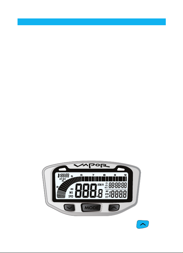
Overview
Vapor Computer:
Vapor holds a large amount of information in a small space. There
are three buttons for easy navigation, two LED’s for alerts and
warnings, and a brightly lit LCD panel for easy viewing.
YELLOW
LED
LCD
SCREEN
LEFT BUTTON MODE BUTTON RIGHT BUTTON
RED LED
Quickstart Commands:
• <MODE> = Switch between screens in Normal Mode.
• <LEFT> + <MODE> = Reset Trip Data: Maximum Speed, Distance,
Ride Time, Stop Watch, Max Engine Temperature, and Max RPM.
• <RIGHT> = Toggle between features in Normal Mode screens.
• <MODE> FOR 3 SEC = Edit Trip Distance (DST) value.
- <LEFT> or <RIGHT> = Increment or scroll distance value.
• <LEFT> <CENTER> + <RIGHT> = Enter Data Setting Mode.
- <MODE> = Move to next data setting screen.
- <LEFT> = Increment or scroll through current data setting.
- <RIGHT> = Move to next digit in data setting mode.
6
Parts & Features
Backlight:
Vapor is equipped with a backlight for easy viewing during night-time
operation.
Using External 12V Power:
• Vapor will light up with all five LED’s.
• Vapor will remain lit as long as it senses wheel movement. After
5 minutes of inactivity Vapor shuts off the backlight. Press any
button, roll the wheels, or start the motor power and Vapor will light
up again.
• Shift and Temperature LED’s will be enabled.
Using Internal Battery Only:
• Vapor will only stay lit for 3 seconds.
• Vapor’s backlight will light up with 10% power to conserve battery
power.
• If the LO symbol is present, the backlight will not turn on. The LO
symbol appears when battery voltage drops below 2.45V.
• If ambient temperature is cold (below -5°C) the backlight will not
ENGINE TEMP
TO ACTIVATE BACKLIGHT MANUALLY, PRESS
If connected to 12V power, press any key to activate the backlight.
7
Parts & Features
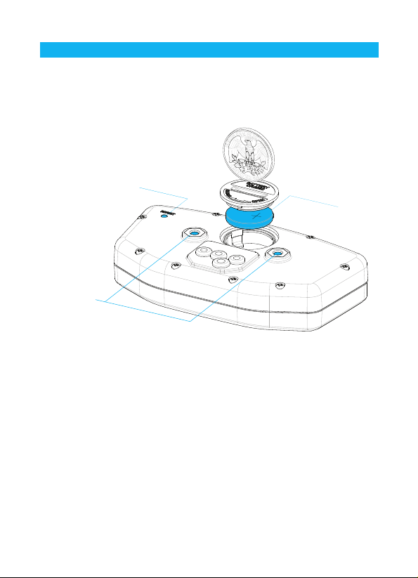
Reset Button:
Use of the Reset Button will erase data for the current ride including
clock and trip distance.
RESET
BUTTON
MOUNTING
HOLES
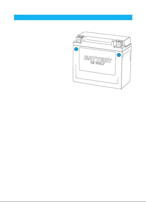
BATTERY
Internal Battery:
Vapor has an internal 3.0V watch type battery (#CR2032). The
computer can be run from this battery alone.
To change the battery, unscrew the battery cap on the back of the
computer with a coin. Make sure the positive side of the battery is
facing up when replaced.
REPLACE WITH BATTERY MODEL NUMBER #CR2032
8
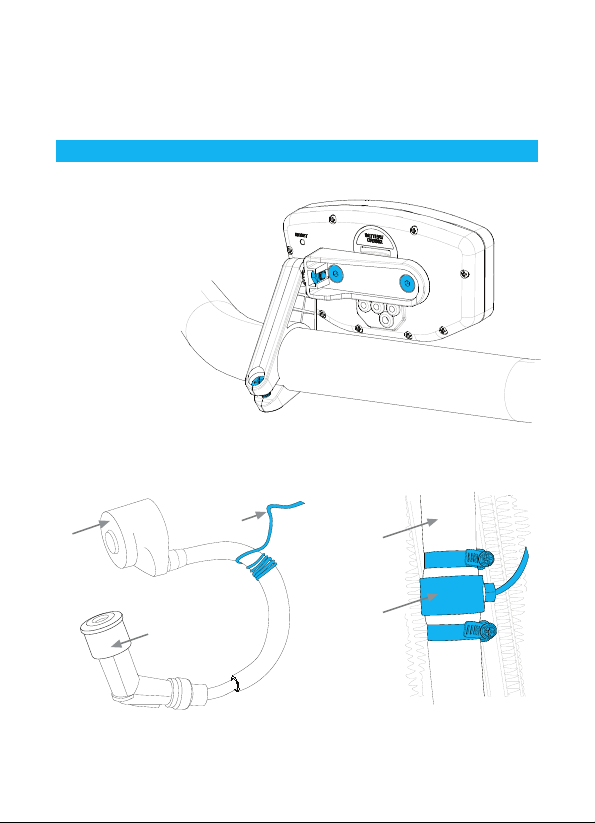
Installation
Bar Mounting:
Place bolts as
shown in picture.
Remember to
use provided
nuts when
placing bolts.
RPM and Temperature Sensors:
Please see model-specific instructions for mounting procedure.
Motorcycle installation shown below.
COIL
RPM
SENSOR
RADIATOR
HOSE
SPARK PLUG
BOOT
RPM Pulse Sensor
wrapped around spark plug wire
TEMP.
SENSOR
Temperature Sensor
in-line in radiator hose
9
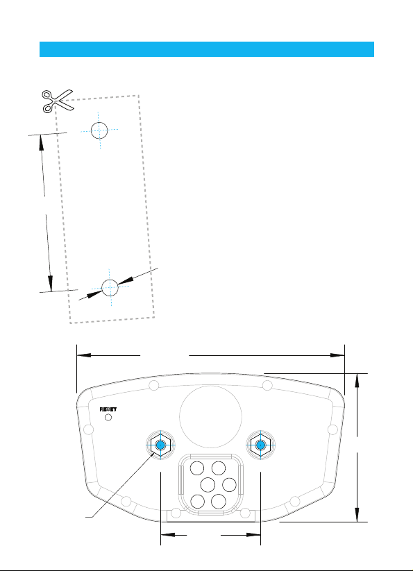
DRILL TEMPLATE
SCALE 1:1
Installation
Flat/Surface Mount:
There are two screw holes on
the back of Vapor. Use the
included M4 bolts to mount to
any flat surface (e.g. stock
odometer mounting bracket or
body panel).
40mm
Mounting
Accepts
M4 Bolts
10
Hole
Drill Size:
• 4.2mm
• 0.165”
• M4
107.5mm
Make sure that the cables will
not be chafed or damaged in
their mounting location.
If other than provided screws
are used, make sure they are
not too long for mounting holes.
Screws that are too long will
damage internal components of
Vapor.
59.5mm
40mm
Installation
12 Volt Systems:
If possible, install Vapor to a 12
volt system:
• The backlight will be 10 times
brighter.
• Vapor will enter sleep mode
after 20 minutes instead of 5.
• The shift and and temperature
indicator LED’s will be
enabled.
OPTION 1) BATTERY WIRED:
Connect the power cables
directly to the vehicle’s 12 volt battery.
A 1 Amp fuse (not provided) should be used between the power cable
and positive battery terminal when connecting directly to a battery.
OPTION 2) SYSTEM TAP:
As an alternative to running wires all the way to the battery, it is
possible to tap into the electrical system. When tapping into the
electrical system, connect to a circuit protected by fuse. It is best to
connect so power is not interrupted by key switch.
Notes:
• Vapor is polarity
negative post on the battery.
• Vapor will not drain your battery.
• The “LO” low battery indicator will activate if battery voltage drops
below 2.45V.
independent. Either lead can go to the positive or
11
Installation
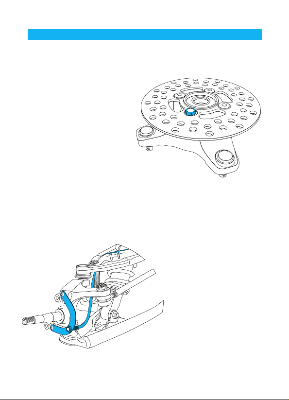
ATV Sensor/Magnet Installation:
Vapor needs two things to be
able to collect distance data:
1. A magnet placed on the
spinning part of the wheel.
2. The sensor, placed on the
non-moving part of the wheel.
The magnet spins around
tripping the sensor switch
each time--data collected lets
Vapor calculate distance and
time.
The magnet gets installed on the brake rotor because it spins with
the wheel. Typically the provided magnetic bolt can simply replace
a stock rotor bolt (see above picture). If that doesn’t work, there is
Magnetic Bolt Installation
ATV Rotor
a spare magnet that can be
glued in a hole on the brake
rotor. (JB Weld or a similar
slow-cure epoxy works
well.)
After the magnet is in, the
sensor is placed on a nonspinning part the wheel.
C-Bracket Installation-ATV Left Axle
12
The sensor typically is
placed on either the
provided C-bracket or the
ATV metal rotor shield.
Installation
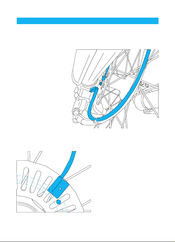
Motorcycle Sensor/Magnet Installation:
Motorcycles, like ATV’s,
need a magnet placed on
the spinning part of the
wheel and the sensor
installed to a non-spinning
part.
The magnet typically gets
bolted or glued to the
brake rotor.
The sensor wire should
come from the back of the
computer, be cable-tied to
the brake line as it travels
down the front forks, then
attached to the brake
caliper.
Optimum Magnet Rotation Path
Magnet About to Pass Under Sensor
Vapor can tell how far and fast
it’s traveled by keeping track of
how many times the magnet
passes under the sensor switch.
Many Motorcycles and ATV’s
have special installation
procedures. Refer to the
provided installation insert for
specific instructions for your
machine or visit
www.TrailTech.net.
13
 Loading...