


2
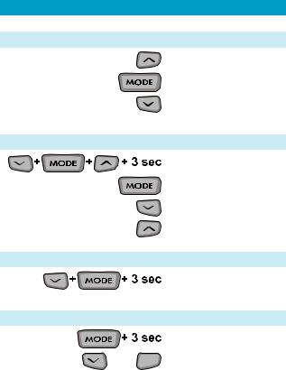
Quick-start
Normal Mode
Backlight
Switch Screens
Stop Watch
Setup Mode
Enter Setup
Switch Screens
Scroll Value
Next Digit
Data Reset
Reset Ride Data
Adjust Trip Distance Mode
Enter / Exit
or  Scroll Value
3

A Note to You
Trail Tech brings functionality and life to your motor vehicle with high quality and innovation. To ensure long and trouble-free operation, this User’s Manual contains valuable information about how to operate and maintain your digital gauge properly.
Please read this manual carefully.
If you call to request service for your Striker digital gauge, you need the date of purchase, dealer’s name, address, and telephone number. Warranty service requires proof of purchase.
PURCHASE DATE
DEALER NAME
DEALER ADDRESS
DEALER PHONE
Keep this book and sales slip together for future reference.
4

Precautions
WARNING
•Read all instructions before using Striker.
•Avoid contact with gasoline, degreasers or other chemical cleaners.
•Striker can be used in the rain but should not be used underwater.
•Do not wash with pressure washer.
•When installing Striker, disconnect the vehicle battery.
•When installing radiator hose temperature sensors, make sure it fits BEFORE cutting the radiator hose.
•Do not leave the main unit in direct sunlight when not riding.
•Check gap between speed sensor and magnet periodically.
•Do not bend, twist, kink or abuse the sensor cables.
•To reduce the risk of injury, do not disassemble Striker or its accessories.
PAY ATTENTION TO THE TRAIL!
5
Specifications
|
|
|
|
|
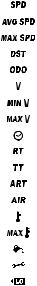
FUNCTION |
ICON |
UNITS |
RANGE |
|
Current Speed |
|
KM/H or M/H |
4 |
- 299.9 |
|
|
|
|
|
Average Speed |
|
KM/H or M/H |
4 |
- 299.9 |
Maximum Speed |
|
KM/H or M/H |
4 |
- 299.9 |
(Trip) Distance |
|
KM or M |
0.00 - 299999 |
|
Odometer |
|
KM or M |
0.00 - 299999 |
|
|
|
|
|
|
Voltage |
|
VAC/VDC |
1.6-52.6 |
|
Minimum Voltage |
|
VAC/VDC |
1.6-52.6 |
|
Maximum Voltage |
|
VAC/VDC |
1.6-52.6 |
|
Hourmeter / Clock |
|
H:M:S |
12h or 24h |
|
|
|
|
|
|
Ride Time |
|
H:M:S |
0:0:0 - 9999:59 |
|
Stop Watch |
|
H:M:S |
0:0:0 - 9999:59 |
|
Accum. Ride Time |
|
H:M:S |
0:0:0 - 9999:59 |
|
Air Temperature |
|
ºC or ºF |
0 |
- 999º |
|
|
|
|
|
Engine Temperature |
|
ºC or ºF |
0 |
- 999º |
Max Engine Temp |
|
ºC or ºF |
0 |
- 999º |
Oil Reminder |
|
KM/H or M/H |
0.0 - 9999 |
|
Care Reminder |
|
KM/H or M/H |
0.0 - 9999 |
|
Low Battery |
|
3V |
~ 1 year life |
|
Tire Size |
|
mm |
0 |
- 3999 mm |
|
|
|
|
|
6

Specifications
PHYSICAL FEATURE |
DESCRIPTION |
Speed/Distance Sensor |
Non-contact Magnetic Sensor |
Temperature Sensors |
External Ambient and |
|
Engine Thermistor Sensors |
Voltage Sensor |
Red/Black Power Wire |
Remote Thumb Switch |
Optional, Mirrors Main Buttons |
Backlight |
5 White LED Group |
Product Dimensions |
106.93x59.46x23.7mm WxHxD |
|
(4.21x2.34x0.93”) |
Screen Dimensions |
78.75 x 28.6mm (3.1 x 1.13”) |
Product Weight |
3.9 oz. (110 grams) (0.24 lbs.) |
Wheel Circumference |
0 to 3999 mm |
Operation Temperature |
0°C to 60°C (32°F to 140°F) |
Storage Temperature |
-20°C to 80°C (-4°F to 176°F) |
Battery |
3V CR2032 (About 1 Year life) |
External Power Input |
9.0-400 VAC (No Polarity) |
|
9.0-55.0 VDC (No Polarity) |
Critical Environment |
Amber/Red LED Alert System |
|
|
7
Physical Features
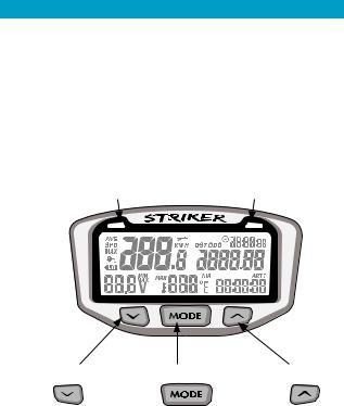
Striker Computer:
Main Computer:
•The Striker computer has 3 buttons and 2 LED’s.
LEDs:
•Amber Warning LED: Voltage [Flash], Temperature [Solid]
•Red Danger LED: Voltage [Flash], Temperature [Solid]
AMBER LED |
RED LED |
||
|
|
|
|
|
|
|
|
LEFT BUTTON |
CENTER BUTTON RIGHT BUTTON |
8
Physical Features
The
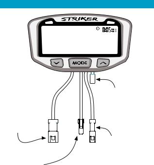
Wires:
Temperature |
|
|
||||||||||
|
|
|||||||||||
Sensor: |
|
Ambient |
||||||||||
The temperature |
|
Temperature |
||||||||||
sensor is mounted in |
|
Sensor |
||||||||||
the radiator hose or |
|
|
||||||||||
cylinder head. |
|
|
|
|
|
|
|
|
|
Power Cable: |
||
|
|
|
|
|
|
|
|
|||||
|
|
|
|
|
|
|
|
|
|
|
|
|
|
|
|
|
|
|
|
|
|
|
|
|
|
|
|
|
|
|
|
|
|
|
|
|
|
|
|
|
|
|
|
|
|
|
|
|
|
|
|
|
|
|
|
|
|
|
|
|
|
|
|
The power wire |
|
|
|
|
|
|
|
|
|
|
|
|
connects anywhere |
Speed Sensor: |
|
in the vehicle’s |
||||||||||
The speed sensor is mounted |
|
electrical circuit, |
||||||||||
to the brake caliper on the |
|
or straight to the |
||||||||||
wheel. Without the speed |
|
battery terminals. |
||||||||||
sensor mounted, Striker |
|
|
||||||||||
cannot display speed or gather |
|
|
||||||||||
distance data. |
|
|
||||||||||
9
Physical Features
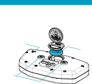
Reset Button:
Use of the reset button will erase data for the current ride including stop watch and trip distance. ODO and ART are permanent.
RESET
BUTTON
BATTERY
MOUNTING
HOLES
Internal Battery:
•Striker has an internal 3.0V watch type battery (#CR2032). The computer can be run from the internal battery without being connected to a vehicle power source. For proper, full-featured use (LEDs and voltage readouts), connect to vehicle power.
•To change the battery, unscrew the battery cap on the back of the computer with a coin. Make sure the positive side of the battery is facing up when replaced.
•REPLACE WITH BATTERY MODEL NUMBER #CR2032
10
Physical Features
Bar Mounting:
Place nuts and bolts as shown in picture.
Temperature Sensors:
Please see-model-specific instructions for mounting procedure.
SPARK
PLUG
Cylinder Head Temperature
Sensor for air-cooled machines.
RADIATOR
HOSE
TEMP.
SENSOR
Temperature Sensor in-line in radiator hose for water-cooled machines.
11
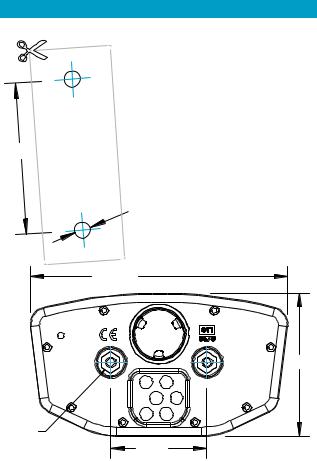
DRILL TEMPLATE
SCALE 1:1
40mm
107.5mm
Physical Features
Flat/Surface Mount:
There are two screw holes on the back of Striker. Use the included M4 bolts to mount to any flat surface.
If other than provided screws are used, make sure they are not too long for mounting holes.
Screws that are too long will damage internal components of Striker.
RESET
59.5mm
Mounting
Hole
Accepts
M4 Bolts
12 |
40mm |

Physical Features
12 Volt Systems:
Connect to 12 volt system:
• The backlight will be 5x brighter.
• The temperature and voltage indicator LEDs will be enabled.
• The voltage readout will function.
OPTION 1) BATTERY WIRED:
Connect the power cables directly to the vehicle’s 12 volt battery.
OPTION 2) SYSTEM TAP:
As an alternative to running wires all the way to the battery, it is possible to tap into the electrical system. It is best to connect so power is not interrupted by the key switch.
•The “LO” indicator will activate if voltage drops below 2.45V.
•Striker draws too little power to drain the vehicle battery.
•Striker is polarity
independent. |
Power Wire |
13
Physical Features
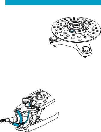
ATV Sensor/Magnet Installation:
Striker needs two things to be able to collect distance data:
1. |
A magnet placed on the |
|
spinning part of the wheel. |
|
|
2. |
A speed sensor, placed |
|
on the stationary part of the |
|
|
wheel. |
ATV Magnet Bolt |
|
The magnet spins around tripping the sensor switch each time-- giving Striker speed, distance and time data.
The magnet is installed on the brake rotor because it spins with the wheel. The provided magnetic bolt can simply replace a stock rotor bolt (see above picture). If that will not work, glue the spare
magnet in a hole on the
brake rotor. (JB Weld or
a similar slow-cure epoxy works well.)
After the magnet is in, the sensor is placed on a nonspinning part the wheel, rotor shield, or provided bracket.
14
 Loading...