

Page 1
Rev: 1.1.0
1910011678
TL-MR6400
300Mbps Wireless N 4G LTE Router
Page 2

COPYRIGHT & TRADEMARKS
Specifications are subject to change without notice. is a registered trademark of
TP-LINK TECHNOLOGIES CO., LTD. Other brands and product names are trademarks or
registered trademarks of their respective holders.
No part of the specifications may be reproduced in any form or by any means or used to make
any derivative such as translation, transformation, or adaptation without permission from
TP-LINK TECHNOLOGIES CO., LTD. Copyright © 2016 TP-LINK TECHNOLOGIES CO., LTD.
All rights reserved.
http://www.tp-link.com
I
Page 3

Symbol
Explanation
DC voltage
CE Mark Warning
This is a class B product. In a domestic environment, this product may cause radio interference,
in which case the user may be required to take adequate measures.
RF Exposure Information
This device meets the EU requirements (1999/5/EC Article 3.1a) on the limitation of exposure of
the general public to electromagnetic fields by way of health protection.
The device complies with RF specifications when the device used at 20 cm from your body.
Продукт сертифіковано згідно с правилами системи УкрСЕПРО на відповідність вимогам
нормативних документів та вимогам, що передбачені чинними законодавчими актами
України.
Safety Information
When product has power button, the power button is one of the way to shut off the product;
when there is no power button, the only way to completely shut off power is to disconnect the
product or the power adapter from the power source.
Don’t disassemble the product, or make repairs yourself. You run the risk of electric shock
and voiding the limited warranty. If you need service, please contact us.
Avoid water and wet locations.
Adapter shall be installed near the equipment and shall be easily accessible.
The plug considered as disconnect device of adapter.
Use only power supplies which are provided by manufacturer and in the original
packing of this product. If you have any questions, please don't hesitate to contact us.
Explanation of the symbols on the product label
II
Page 4

RECYCLING
This product bears the selective sorting symbol for Waste electrical and electronic
equipment (WEEE). This means that this product must be handled pursuant to
European directive 2012/19/EU in order to be recycled or dismantled to minimize
its impact on the environment.
User has the choice to give his product to a competent recycling organization or to
the retailer when he buys a new electrical or electronic equipment.
III
Page 5

TP-LINK TECHNOLOGIES CO., LTD
DECLARATION OF CONFORMITY
For the following equipment:
Product Description: 300Mbps Wireless N 4G LTE Router
Model No.: TL-MR6400
Trademark: TP-LINK
We declare under our own responsibility that the above products satisfy all the technical
regulations applicable to the product within the scope of Council Directives:
Directive 1999/5/EC, Directive2011/65/EU, 2009/125/EC
The above product is in conformity with the following standards or other normative documents
EN 300328 V1.9.1
EN 301511 V9.0.2
EN 301908-1 V7.1.1 & EN 301908-2 V6.2.1 & EN 301908-13 V6.2.1
EN 301489-1 V1.9.2 & EN 301489-7 V1.3.1 & EN 301489-17 V2.2.1 & EN 301489-24 V1.5.1
EN 55022: 2010+AC: 2011
EN 55024: 2010
EN 60950-1: 2006 + A11: 2009 + A1: 2010 + A12: 2011 +A2: 2013
EN 50385: 2002
EN 62311: 2008
EN 61000-3-2:2014
EN 61000-3-3:2013
(EC) No 278/2009
(EC) No 1275/2008
(EU) No 801/2013
The product carries the CE Mark:
Person responsible for making this declaration:
Huang Jing
Regulatory Compliance Manager
Date of issue: 2016-03-10
TP-LINK TECHNOLOGIES CO., LTD.
Building 24 (floors 1, 3, 4, 5), and 28 (floors 1-4) Central Science and Technology Park,
Shennan Rd, Nanshan, Shenzhen, China
Page 6

CONTENTS
Package Contents ............................................................................................................................. 1
Chapter 1. Introduction ................................................................................................................... 2
1.1 Overview of the router .................................................................................................... 2
1.2 Conventions .................................................................................................................... 2
1.3 Main Features ................................................................................................................. 2
1.4 Panel Layout ................................................................................................................... 4
1.4.1 The Front Panel .................................................................................................. 4
1.4.2 The Rear Panel ................................................................................................... 5
Chapter 2. Connecting the router .................................................................................................. 6
2.1 System Requirements .................................................................................................... 6
2.2 Installation Environment Requirements .......................................................................... 6
2.3 Connecting the router ..................................................................................................... 6
Chapter 3. Quick Installation Guide ............................................................................................... 9
3.1 3G/4G Router Mode ....................................................................................................... 9
3.2 Standard Wireless Router Mode ................................................................................... 11
Chapter 4. Router Configuration-3G/4G Router Mode ................................................................ 20
4.1 Login ............................................................................................................................. 20
4.2 Status ............................................................................................................................ 20
4.3 Quick Setup .................................................................................................................. 21
4.4 WPS .............................................................................................................................. 21
4.5 Working Mode ............................................................................................................... 24
4.6 Network ......................................................................................................................... 24
4.6.1 LTE Dial Up ....................................................................................................... 24
4.6.2 LTE Data Settings ............................................................................................. 26
4.6.3 PIN Management .............................................................................................. 27
4.6.4 LAN ................................................................................................................... 28
4.7 SMS .............................................................................................................................. 28
4.7.1 Inbox ................................................................................................................. 29
4.7.2 New Message ................................................................................................... 29
4.7.3 Outbox ............................................................................................................... 30
4.7.4 Draft Box ........................................................................................................... 30
4.7.5 SMS Settings .................................................................................................... 31
4.8 Wireless ........................................................................................................................ 31
4.8.1 Wireless Settings .............................................................................................. 31
I
Page 7

4.8.2 Wireless Security .............................................................................................. 33
4.8.3 Wireless MAC Filtering ..................................................................................... 37
4.8.4 Wireless Advanced ........................................................................................... 39
4.8.5 Wireless Statistics ............................................................................................. 40
4.9 Guest Network .............................................................................................................. 41
4.9.1 Wireless Settings .............................................................................................. 41
4.9.2 Wireless Statistics ............................................................................................. 42
4.10 DHCP ............................................................................................................................ 43
4.10.1 DHCP Settings .................................................................................................. 43
4.10.2 DHCP Client List ............................................................................................... 44
4.10.3 Address Reservation......................................................................................... 45
4.11 Forwarding .................................................................................................................... 46
4.11.1 Virtual Servers................................................................................................... 46
4.11.2 Port Triggering .................................................................................................. 48
4.11.3 DMZ .................................................................................................................. 50
4.11.4 UPnP ................................................................................................................. 50
4.12 Security ......................................................................................................................... 51
4.12.1 Basic Security ................................................................................................... 51
4.12.2 Local Management ........................................................................................... 53
4.12.3 Remote Management ....................................................................................... 54
4.13 Parental Control ............................................................................................................ 55
4.14 Access Control .............................................................................................................. 57
4.14.1 Rule ................................................................................................................... 57
4.14.2 Host ................................................................................................................... 63
4.14.3 Target ................................................................................................................ 64
4.14.4 Schedule ........................................................................................................... 66
4.15 Advanced Routing ........................................................................................................ 68
4.15.1 Static Routing List ............................................................................................. 68
4.15.2 System Routing Table ....................................................................................... 69
4.16 IP & MAC Binding ......................................................................................................... 70
4.16.1 Binding Settings ................................................................................................ 70
4.16.2 ARP List ............................................................................................................ 71
4.17 Dynamic DNS ............................................................................................................... 72
4.17.1 dyn.com DDNS ................................................................................................. 72
4.17.2 www.noip.com DDNS........................................................................................ 73
4.18 System Tools ................................................................................................................. 74
4.18.1 SNMP ................................................................................................................ 74
II
Page 8

4.18.2 Time Settings .................................................................................................... 76
4.18.3 Diagnostic ......................................................................................................... 77
4.18.4 Firmware Upgrade ............................................................................................ 79
4.18.5 Factory Defaults ................................................................................................ 80
4.18.6 Backup & Restore ............................................................................................. 80
4.18.7 Reboot ............................................................................................................... 81
4.18.8 TR069 ............................................................................................................... 81
4.18.9 Password .......................................................................................................... 82
4.18.10 System Log....................................................................................................... 83
Chapter 5. Router Configuration—Standard Wireless Router Mode ....................................... 85
5.1 Login ............................................................................................................................. 85
5.2 Status ............................................................................................................................ 85
5.3 Quick Setup .................................................................................................................. 86
5.4 WPS .............................................................................................................................. 86
5.5 Working Mode ............................................................................................................... 86
5.6 Network ......................................................................................................................... 87
5.6.1 WAN .................................................................................................................. 87
5.6.2 MAC Clone ........................................................................................................ 97
5.6.3 LAN ................................................................................................................... 97
5.6.4 VLAN ................................................................................................................. 98
5.7 Wireless ........................................................................................................................ 99
5.8 Guest Network .............................................................................................................. 99
5.8.1 Wireless Settings ............................................................................................ 100
5.8.2 Wireless Statistics ........................................................................................... 101
5.9 DHCP .......................................................................................................................... 101
5.10 Forwarding .................................................................................................................. 101
5.11 Security ....................................................................................................................... 102
5.11.1 Basic Security ................................................................................................. 102
5.11.2 Advanced Security .......................................................................................... 103
5.11.3 Local Management ......................................................................................... 105
5.11.4 Remote Management ..................................................................................... 106
5.12 Parental Control .......................................................................................................... 107
5.13 Access Control ............................................................................................................ 107
5.14 Advanced Routing ...................................................................................................... 107
5.15 Bandwidth Control....................................................................................................... 107
5.15.1 Control Settings .............................................................................................. 107
5.15.2 Rule List .......................................................................................................... 108
III
Page 9

5.16 IP & MAC Binding ....................................................................................................... 108
5.17 Dynamic DNS ............................................................................................................. 109
5.18 IPv6 Support ............................................................................................................... 109
5.18.1 IPv6 Status ...................................................................................................... 109
5.18.2 IPv6 Setup....................................................................................................... 110
5.19 System Tools ................................................................................................................111
5.19.1 SNMP ...............................................................................................................111
5.19.2 Time Settings .................................................................................................. 113
5.19.3 Diagnostic ....................................................................................................... 114
5.19.4 Firmware Upgrade .......................................................................................... 116
5.19.5 Factory Defaults .............................................................................................. 117
5.19.6 Backup & Restore ........................................................................................... 117
5.19.7 Reboot ............................................................................................................. 118
5.19.8 TR069 ............................................................................................................. 118
5.19.9 Password ........................................................................................................ 119
5.19.10 System Log..................................................................................................... 120
5.19.11 Statistics .......................................................................................................... 121
Appendix A: FAQ ........................................................................................................................... 123
Appendix B: Configuring the PC ................................................................................................. 125
Appendix C: Specifications ......................................................................................................... 130
Appendix D: Glossary ................................................................................................................... 132
IV
Page 10

TL-MR6400
300Mbps Wireless N 4G LTE Router
Package Contents
The following items should be found in your package:
300Mbps Wireless N 4G LTE Router TL-MR6400
Power Adapter for TL-MR6400
Ethernet cable
Quick Installation Guide
Micro/Nano to Standard SIM Card Adapter
Note:
Make sure that the package contains the above items. If any of the listed items are damaged or
missing, please contact your distributor.
-1-
Page 11
TL-MR6400
300Mbps Wireless N 4G LTE Router
Chapter 1. Introduction
1.1 Overview of the router
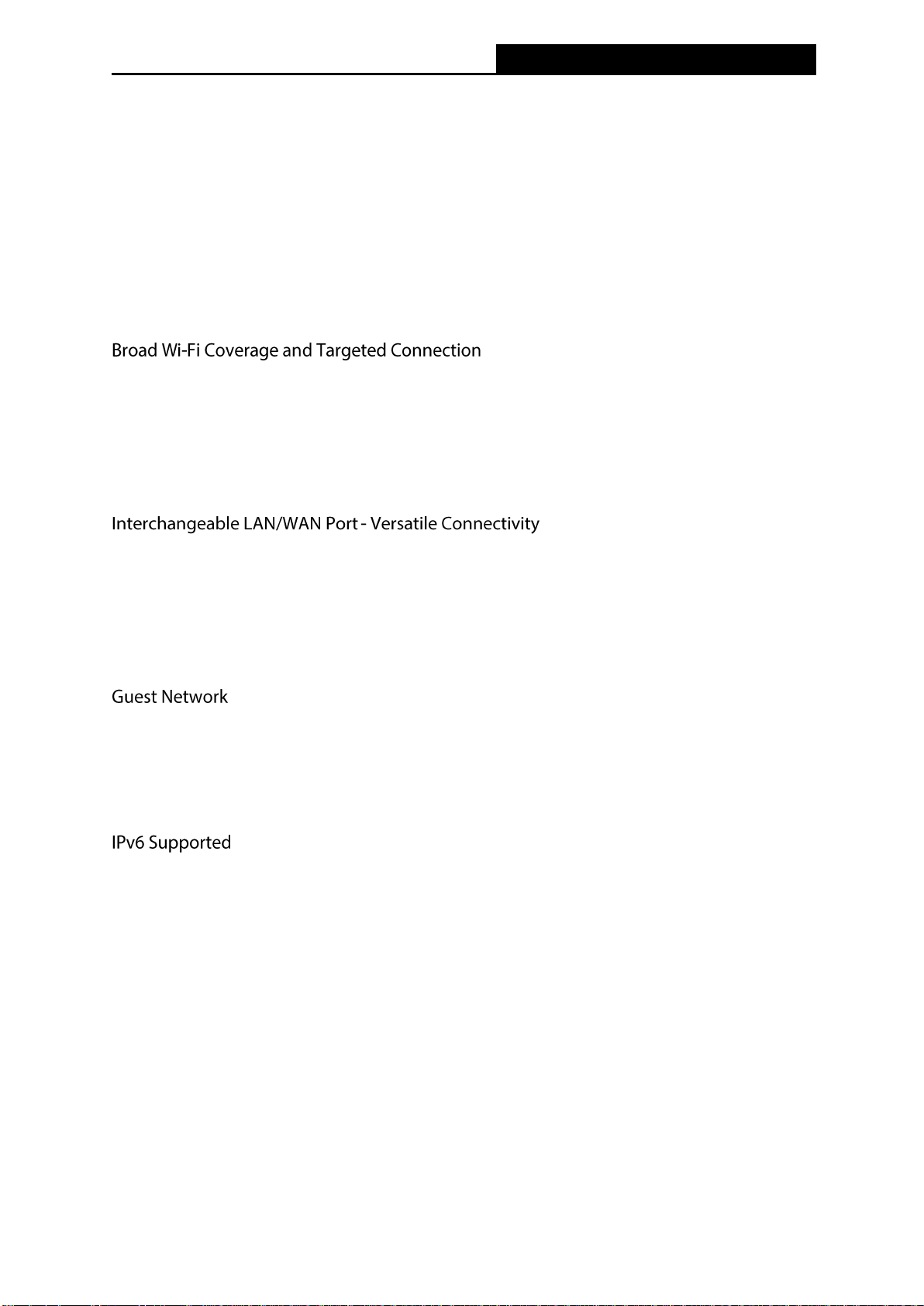
The 300Mbps Wireless N 4G LTE Router, TL-MR6400, shares the latest generation 4G LTE
network with multiple Wi-Fi devices, anywhere you want. It creates a Wi-Fi with speed up to
300Mbps. Also four Ethernet ports add your wired devices to the 4G LTE network.
Featuring two fixed external antennas and high power amplifiers, TL-MR6400 is able to boost
Wi-Fi coverage throughout your home. Advanced Beamforming technology enables
TL-MR6400 to focus Wi-Fi signal to connected devices, delivering a more targeted and highly
efficient wireless connection.
The TL-MR6400 supports 4G LTE or Ethernet WAN connections (EWAN), which allows users to
have the flexibility of different Internet connections among LTE, cable or fiber modem using its
SIM card slot and interchangeable LAN/WAN port. This unique feature makes it easier when
users need to change to fiber or cable services when necessary.
Guest Network Access provides secure Wi-Fi access for guests sharing your home or office
network in a controlled manner without needing to expose private Wi-Fi access codes or other
personal data.
TL-MR6400 supports IPv6, which is the foundation of the next generation of the Internet and
enables a range of new services and improved user experience.
1.2 Conventions
The router or TL-MR6400 mentioned in this guide stands for 300Mbps Wireless N 4G LTE
Router TL-MR6400 without any explanation.
1.3 Main Features
Supports 4G/3G/2G network
LTE: Cat4
-2-
Page 12

TL-MR6400
300Mbps Wireless N 4G LTE Router
FDD-LTE:
800MHz(Band20)/900MHz(Band8)/1800MHz(Band3)/2100MHz(Band1)/2600MHz(Band7)
TDD-LTE: 2300MHz(Band40)、2600MHz(Band38)
DC-HSPA+/ HSPA+/HSPA/UMTS: 900/2100MHz
EDGE/GPRS/GSM: 850/900/1800/1900MHz
4G LTE supported with up to 150Mbps downloads and 50Mbps uploads speeds
Supports 802.11b/g/n
Wireless N speed up to 300Mbps
Ethernet WAN (EWAN) offers another broadband connectivity option for connecting DSL,
cable or fiber modems
Guest Network Access provides secure Wi-Fi access for guests sharing your home or
office network
Parental Controls allow parents or administrators to establish restricted access policies for
children or staff
Bandwidth Control makes it easier for you to manage the bandwidth of devices connected
to the router(Only in EWAN mode)
Easy wireless security encryption at a push of the WPS button
IPv6 supported, meeting the demands for the next generation of Internet
Wi-Fi On/Off Button allows users to turn their wireless radio on or off
WPA-PSK/WPA2-PSK encryptions provide user networks with active defense against
security threats
Quick Setup provides a quick & hassle free installation process
SPI and NAT firewall protects end-user devices from potential attacks across the Internet
-3-
Page 13
TL-MR6400
300Mbps Wireless N 4G LTE Router
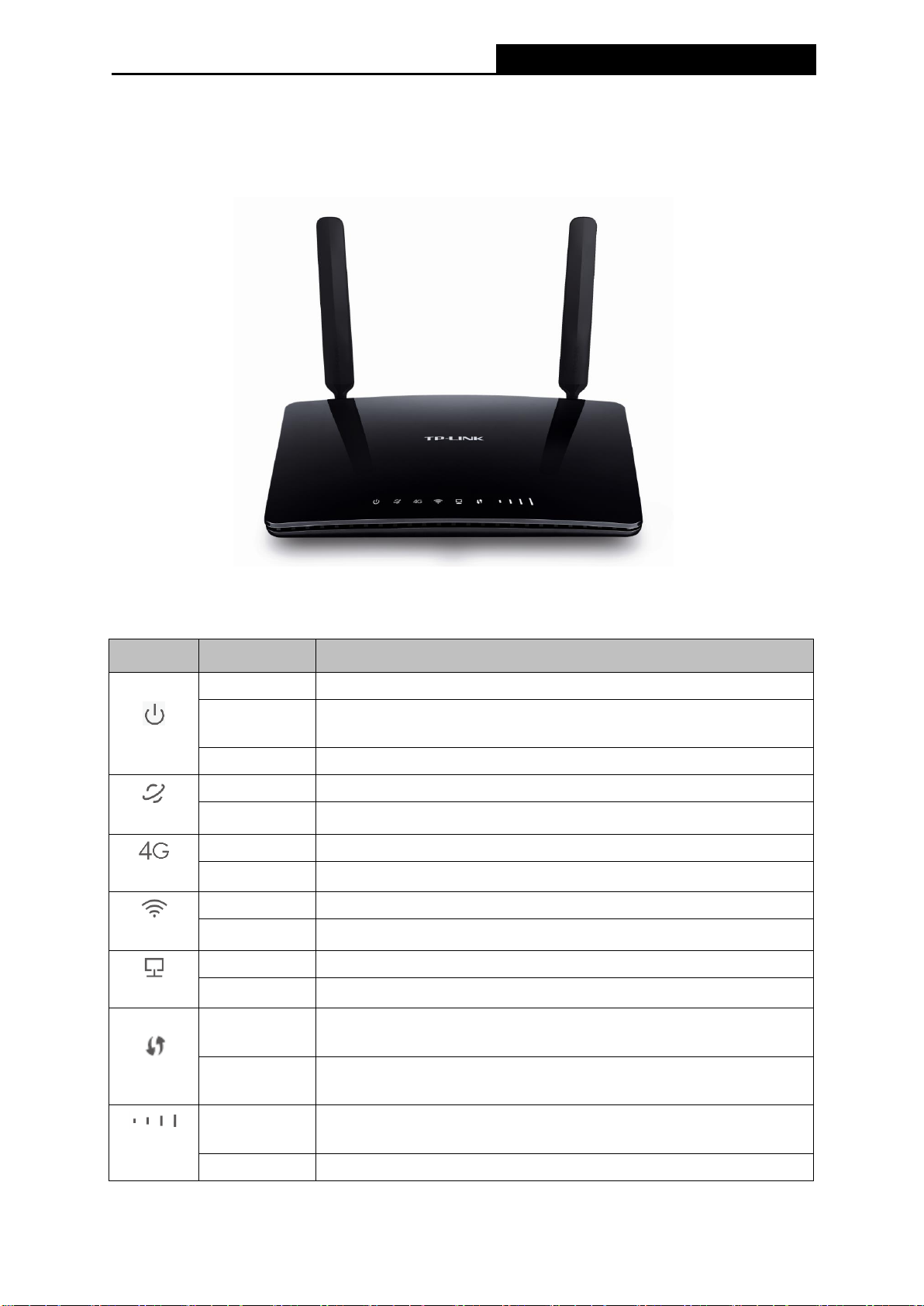
1.4 Panel Layout
Name
Status
Indication
(Power)
On
System initialization is complete.
Flashing
System initializing or firmware upgrading is in process. Do not
disconnect or power off the router.
Off
Power is off.
(Internet)
On
Internet connection is available.
Off
No Internet connection.
(4G)
On
The router is using the 4G network.
Off
The router is using another network other than the 4G network.
(Wireless)
On
The wireless radio is enabled.
Off
The wireless radio is disabled.
(LAN)
On
At least one LAN port is connected.
Off
No LAN port is connected.
(WPS)
On/Off
Turns On when a WPS synchronization is established and
automatically turns Off about 5 minutes later.
Flashing
A wireless device is trying to connect to the network via WPS. This
process may take up to 2 minutes.
(Signal
Strength)
On
Indicates the mobile Internet signal strength the router receives in
the current location. More lit bars indicates a better signal strength.
Off
No signal.
1.4.1 The Front Panel
Figure 1-1 Front Panel sketch
The router’s LEDs are located on the front panel (View from left to right).
Table 1-1 The LEDs description
-4-
Page 14
TL-MR6400
300Mbps Wireless N 4G LTE Router
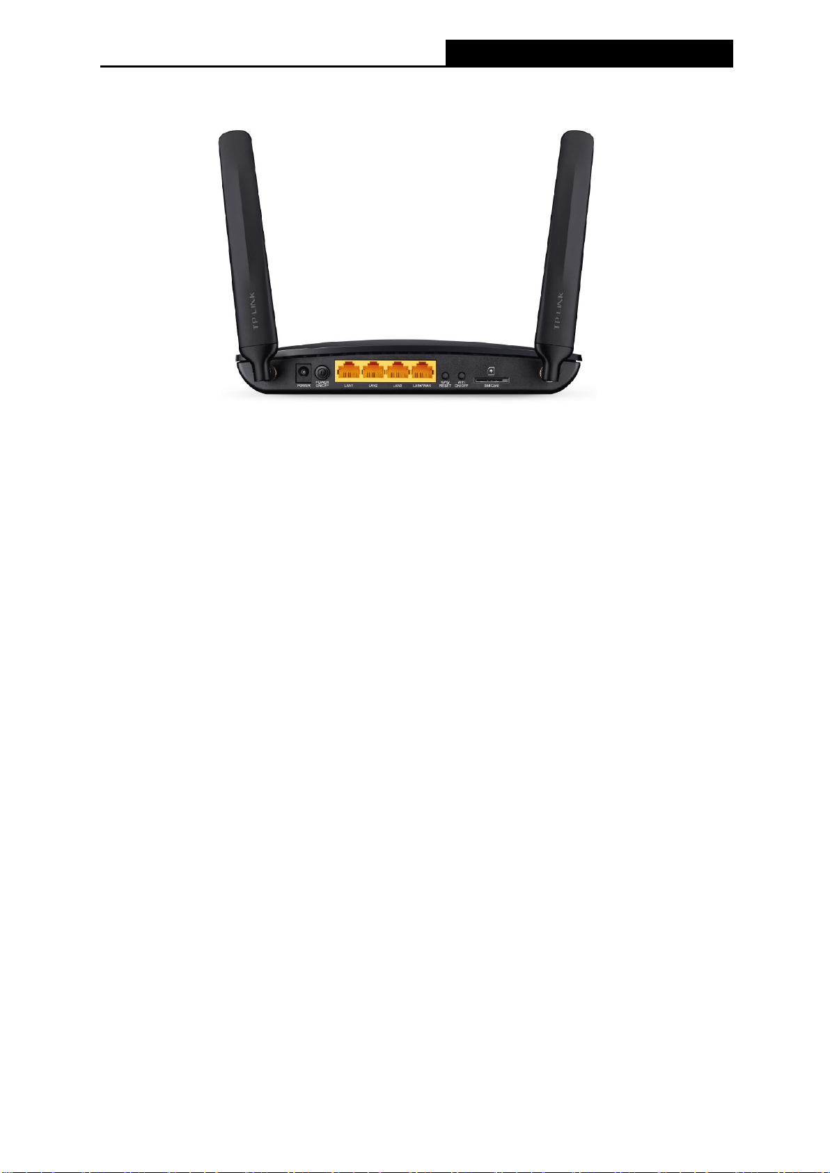
1.4.2 The Rear Panel
Figure 1-2 Rear Panel sketch
The following parts are located on the rear panel (View from left to right).
POWER: The Power socket is where you will connect the power adapter. Please use the
power adapter provided.
POWER ON/OFF: The switch for the power.
LAN (1, 2, 3): These ports (1, 2, 3) connect the router to the local PC(s).
LAN4/WAN: This port can be LAN or WAN port depending on the working mode.
WPS/RESET: This button is used for both WPS and RESET function.
Used as RESET button
With the router powered on, press and hold down the WPS/RESET button on the rear
panel of the router until the Power LED starts flashing. The router will restore and reboot
automatically.
Used as WPS button
If you have client devices, such as wireless adapters, that support Wi-Fi Protected Setup,
then you can press this button to quickly establish a connection between the router and
client devices and automatically configure wireless security for your wireless network.
WiFi ON/OFF: This switch is used to enable/disable the router’s wireless function.
SIM Card: Insert the SIM card into the slot.
-5-
Page 15

TL-MR6400
300Mbps Wireless N 4G LTE Router
Chapter 2. Connecting the router
2.1 System Requirements
SIM card with Internet access enabled
PCs with a working Ethernet Adapter and an Ethernet cable with RJ45 connectors
TCP/IP protocol on each PC
Web browser, such as Microsoft Internet Explorer, Mozilla Firefox or Apple Safari
2.2 Installation Environment Requirements
Place the router in a well-ventilated place far from any heater or heating vent
Avoid direct irradiation of any strong light (such as sunlight)
Keep at least 2 inches (5 cm) of clear space around the router
Operating Temperature: 0℃~40℃ (32℉~104℉)
Operating Humidity: 10%~90%RH, Non-condensing
2.3 Connecting the router
The router supports two modes, 3G/4G router mode and Standard Wireless Router mode.
You can deploy the mode appropriate to your actual network environment. To connect the router,
please take the following steps for different modes.
a. 3G/4G Router Mode
In 3G/4G router mode, with a 3G/4G SIM card, this Router can join a 3G/4G network as well as
act as a wireless central hub to broadcast its SSID. Thus, the other wireless devices can
connect to the router so as to join the same 3G/4G network.
-6-
Page 16
TL-MR6400
300Mbps Wireless N 4G LTE Router
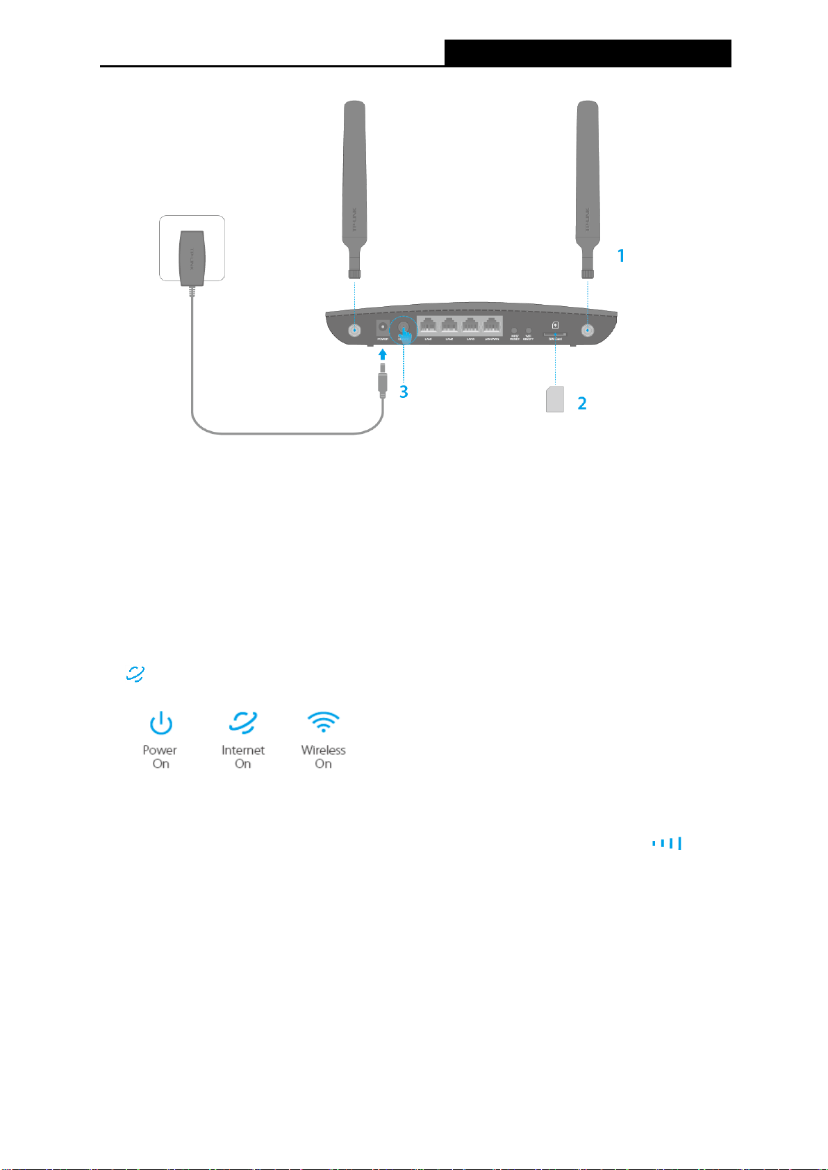
1. Install the 4G LTE antennas and position them upwards.
2. Insert the SIM card into the slot until you hear a click.
Note:
Micro or Nano-SIM card must be converted using a standard SIM card adapter provided by
TP-LINK.
3. Turn on the router.
4. Verify the hardware connection by checking the following LEDs’ status. If the Internet LED
is on, your router is connected to the Internet successfully.
Note:
For better Internet connection, make sure 3 to 4 bars of the Signal Strength LED are
lit. Otherwise, relocate the router to a location that receives a strong mobile Internet signal,
such as near a window.
b. Standard Wireless Router Mode
Before installing the router, make sure your PC is connected to the Internet through the
broadband service successfully. If there is any problem, please contact your ISP. After that,
please install the router according to the following steps. Don't forget to pull out the power plug
and keep your hands dry.
-7-
Page 17

TL-MR6400
300Mbps Wireless N 4G LTE Router
1. Power off your modem (if the modem has a backup battery, please remove it too.), and
disconnect your existing router if you have one.
2. Connect the LAN4/WAN port on your Router to the Modem’s LAN port with an Ethernet
cable.
3. Power on the modem and wait for 2 minutes.
4. Make sure the WiFi ON/OFF switch is ON. Then plug the provided power adapter into the
Power jack and the other end to a standard electrical wall socket. Press the POWER
ON/OFF button to power on the Router. (Before you power on the Router, please make sure
your computer is NOT connected to any other wireless network.)
-8-
Page 18

TL-MR6400
300Mbps Wireless N 4G LTE Router
Chapter 3. Quick Installation Guide
This chapter will show you how to configure the basic functions of your TL-MR6400 using
Quick Setup within minutes.
3.1 3G/4G Router Mode
1. Set up the TCP/IP Protocol in "Obtain an IP address automatically" mode on your PC. If
you need instructions as to how to do this, please refer to Appendix B: Configuring the PC.
2. Connect your computer to the router (wired or wireless).
Wired: Connect your computer to the router's LAN port via an Ethernet cable.
Wireless: Connect wirelessly by using the SSID (network name) and Wireless Password
printed on the product label at the bottom of the router.
3. To access the configuration utility, open a web-browser and type the default address
http://tplinkmodem.net in the address field of the browser.
Figure 3-1 Login the router
4. After a moment, a login window will appear, similar to the Figure 3-2. Enter admin for the
User Name and Password, both in lower case letters. Then click the Login button or press
the Enter key.
Note:
If the above screen does not pop-up, it means that your Web-browser has been set to a proxy.
Go to Tools > Internet Options > Connections > LAN Settings, in the screen that appears,
cancel the Using Proxy checkbox, and click OK to finish it.
Figure 3-2 Login Windows
-9-
Page 19
TL-MR6400
300Mbps Wireless N 4G LTE Router
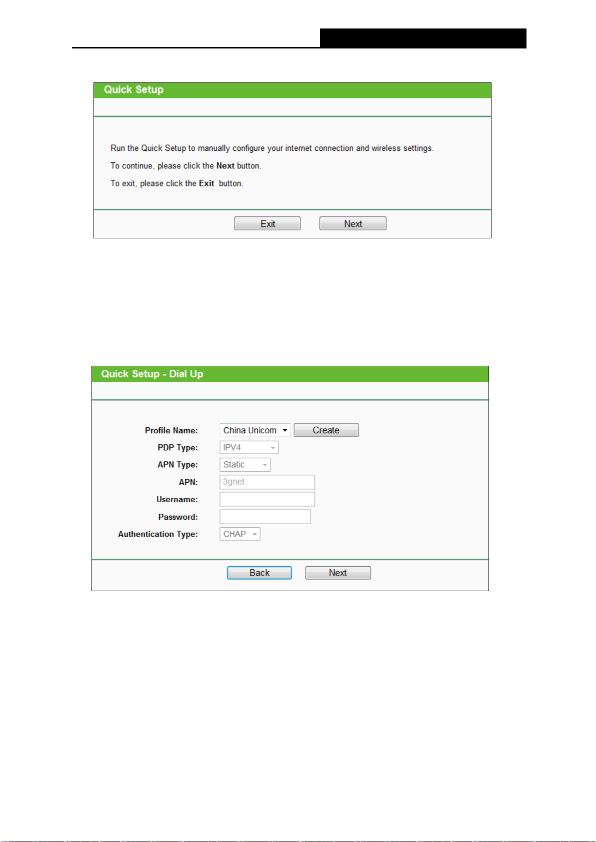
5. Go to Quick Setup and click Next.
Figure 3-3 Quick Setup
6. Choose your Timezone, and then click Next.
7. On the Dial-up Settings page shows the ISP information of the SIM card inserted. Click
Next to continue, if you are sure the information is correct. If these settings are not correct,
please click Create to create a new profile with the correct parameters, and then choose
the new profile from the Profile Name List.
Figure 3-5 Quick Setup – Dial Up
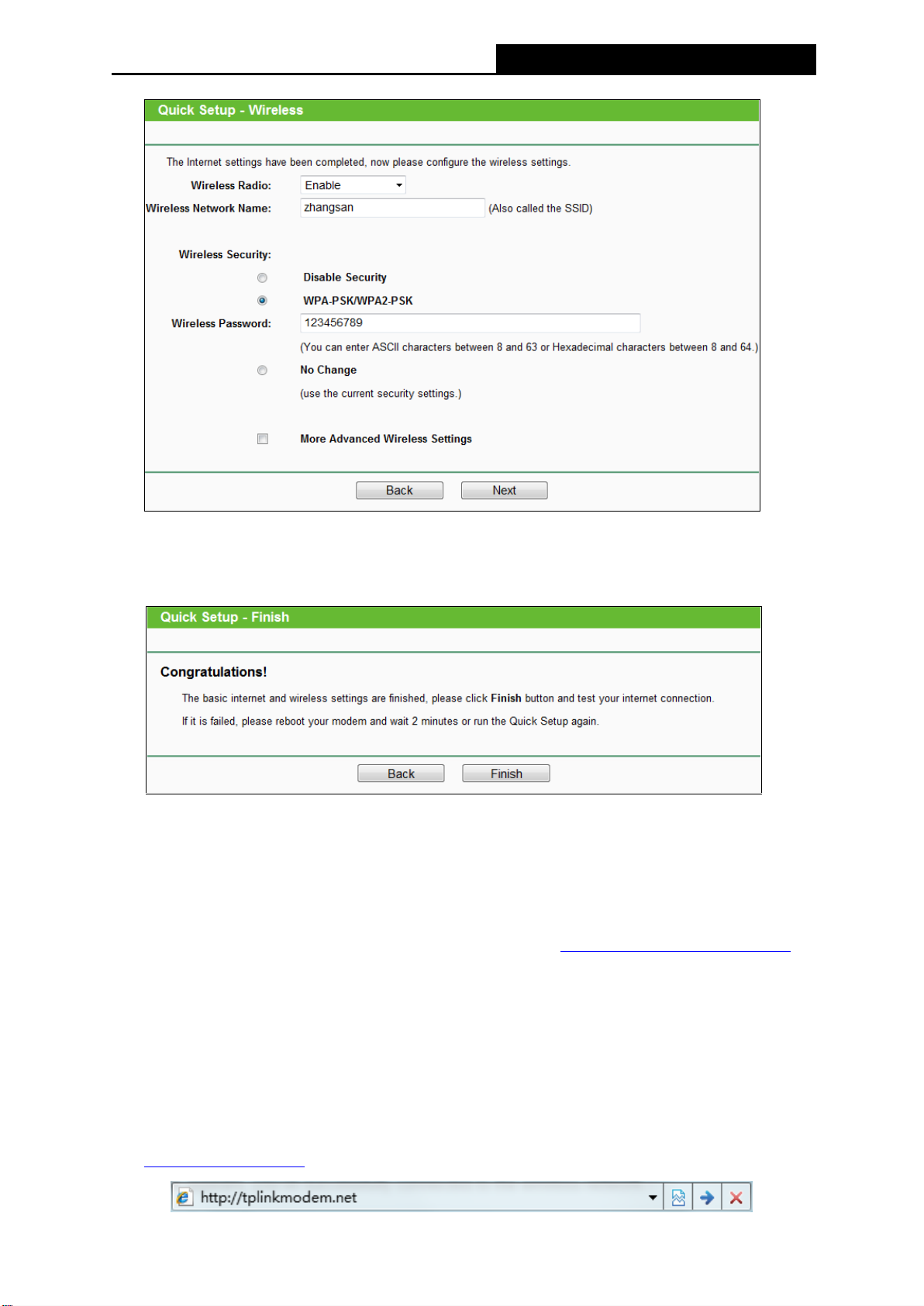
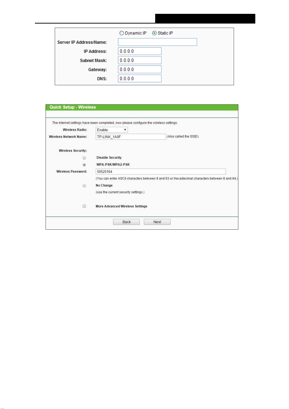
8. Set your wireless parameters. It’s recommended that you edit the following two items, and
then click Next.
1) Create a unique and easy-to-remember Wireless Network Name.
2) Select WPA-PSK/WPA2-PSK under Wireless Security and enter a password in the
field.
-10-
Page 20
TL-MR6400
300Mbps Wireless N 4G LTE Router
Figure 3-6 Quick Setup – Wireless
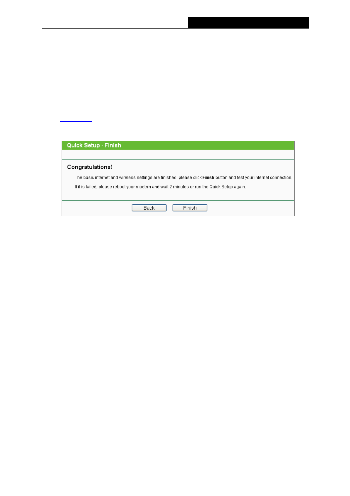
9. Click Finish to make the settings take effect.
Figure 3-7 Quick Setup – Finish
3.2 Standard Wireless Router Mode
1. Set up the TCP/IP Protocol in "Obtain an IP address automatically" mode on your PC. If
you need instructions as to how to do this, please refer to Appendix B: Configuring the PC.
2. Connect your computer to the router (wired or wireless).
Wired: Connect your computer to the router's LAN port via an Ethernet cable.
Wireless: Connect wirelessly by using the SSID (network name) and Wireless Password
printed on the product label at the bottom of the router.
3. To access the configuration utility, open a web-browser and type the default address
http://tplinkmodem.net in the address field of the browser.
-11-
Page 21
TL-MR6400
300Mbps Wireless N 4G LTE Router
Figure 3-8 Login the router
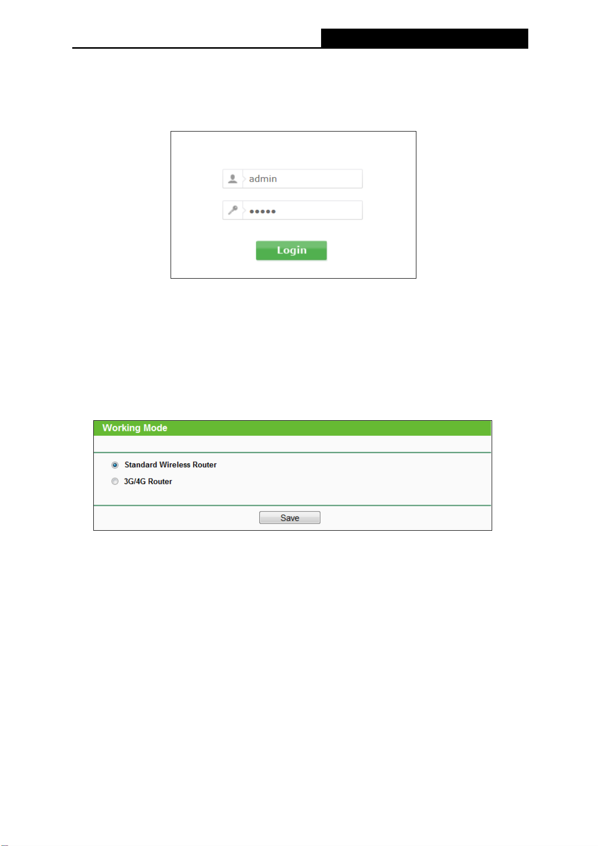
4. After a moment, a login window will appear. Enter admin for the User Name and Password,
both in lower case letters. Then click the Login button or press the Enter key.
Figure 3-9 Login Windows
Note:
If the above screen does not pop-up, it means that your Web-browser has been set to a
proxy. Go to Tools > Internet Options > Connections > LAN Settings, in the screen that
appears, cancel the Using Proxy checkbox, and click OK to finish it.
5. Go to Working Mode page, choose Standard Wireless Router and click Save.
Figure 3-10 Working Mode
Note:
The router will reboot automatically after you click the Save button.
-12-
Page 22

TL-MR6400
300Mbps Wireless N 4G LTE Router
6. Log in to the web management page again, go to Quick Setup and click Next to continue.
Figure 3-11 Quick Setup
7. Choose your Timezone, and then click Next.
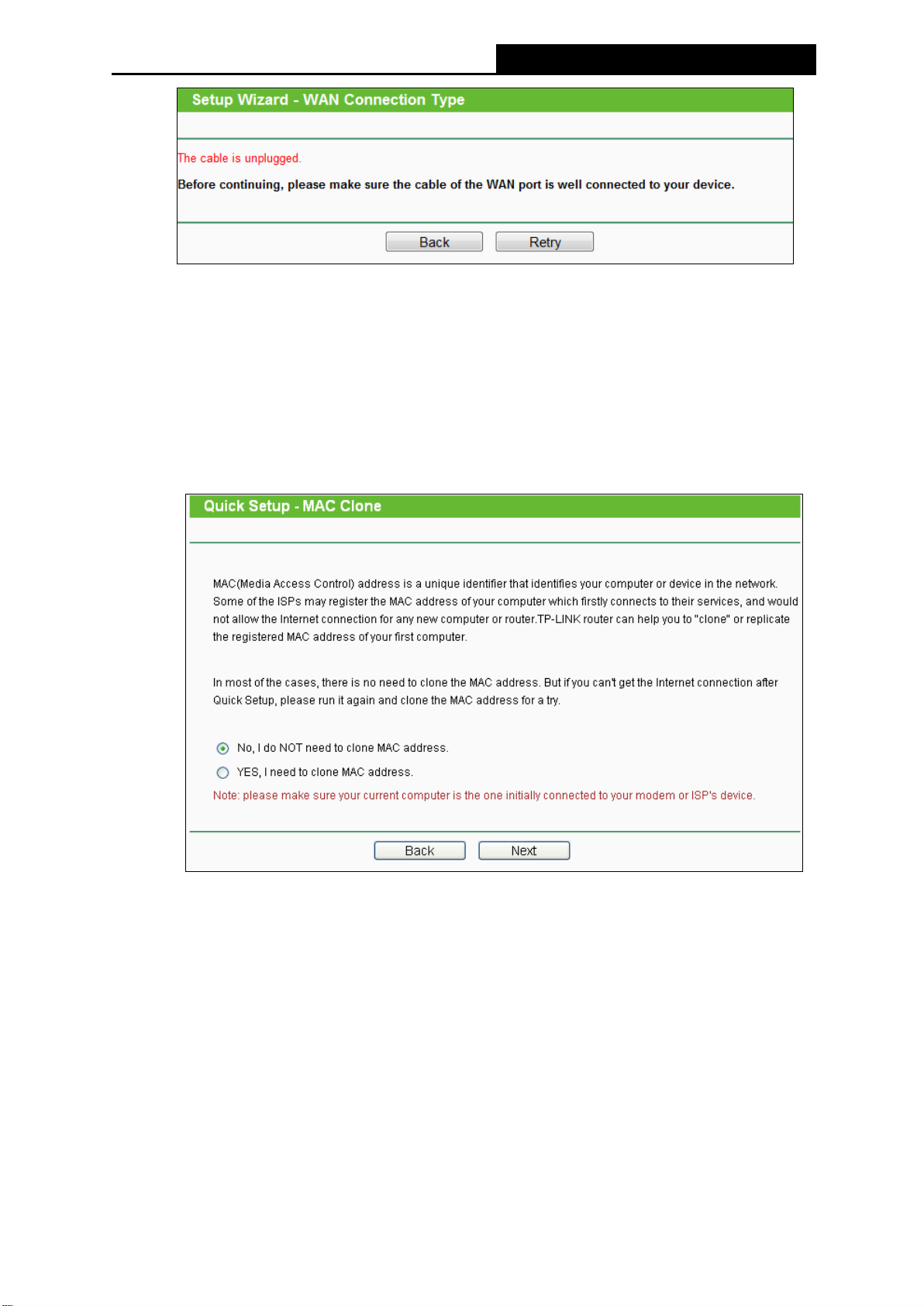
8. Then WAN Connection Type page will appear, shown in Figure 3-13. Select your
connection type if you know what it is or click Auto Detect button.
Note:
1) L2TP and PPTP cannot be detected by the router. You must select it manually.
2) Before continuing, please make sure the cable of the WAN port is well connected to
your device. If the WAN port is not connected, the cable is unplugged page will
appear.
Figure 3-13 Choose WAN Connection Type
-13-
Page 23
TL-MR6400
300Mbps Wireless N 4G LTE Router
9. If you select Auto-Detect, the router will automatically detect the connection type your ISP
provides. The appropriate configuration page will be displayed when an active Internet
service is successfully detected by the router.
If the connection type is Dynamic IP, there will appear the MAC Clone page (as shown
in Figure 3-14). In most cases, there is no need to clone the MAC address. You can
select “No, I do NOT need to clone MAC address” and then click Next. If it is
necessary in your case, please select “Yes, I need to clone MAC address” and then
click Next.
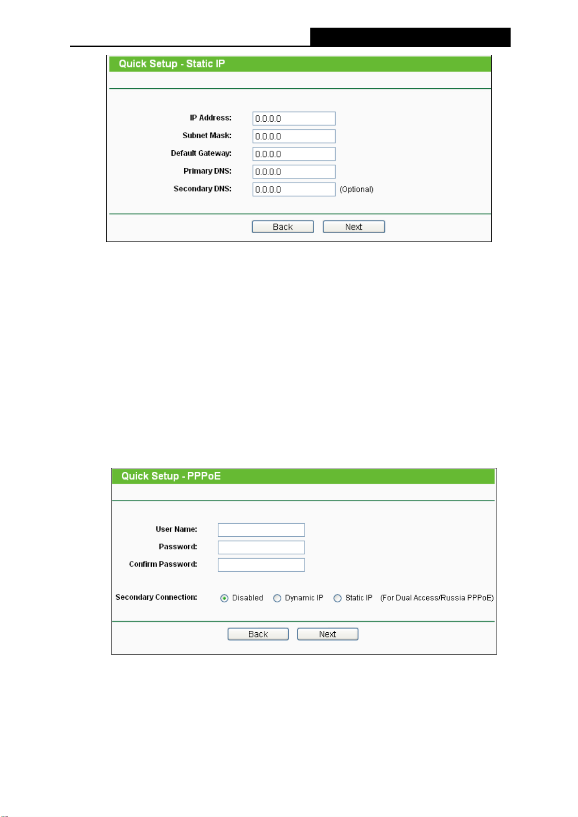
If the connection type is Static IP, the next screen will appear as shown in Figure 3-15.
Figure 3-14 MAC Clone
-14-
Page 24
TL-MR6400
300Mbps Wireless N 4G LTE Router
Figure 3-15 Quick Setup - Static IP
IP Address - This is the WAN IP address as seen by external users on the Internet
(including your ISP). Enter the IP address into the field.
Subnet Mask - The Subnet Mask is used for the WAN IP address, it is usually
255.255.255.0.
Default Gateway - Enter the gateway IP address into the blank.
Primary DNS - Enter the DNS Server IP address into the blank.
Secondary DNS - If your ISP provides another DNS server, enter it into this field.
If the connection type is PPPoE/Russian PPPoE, the next screen will appear.
Configure the following parameters and then click Next to continue.
User Name and Password - Enter the User Name and Password provided by your
ISP. These fields are case sensitive. If you have difficulty with this process, please
contact your ISP.
Figure 3-16 Quick Setup – PPPoE
-15-
Page 25
TL-MR6400
300Mbps Wireless N 4G LTE Router
Confirm Password - Re-enter the password provided by your ISP to ensure the
Password you entered is correct.
Check the radio button of Dynamic/Static IP to activate the secondary connection if your
ISP provides an extra Connection type such as Dynamic/Static IP to connect to a local area
network.
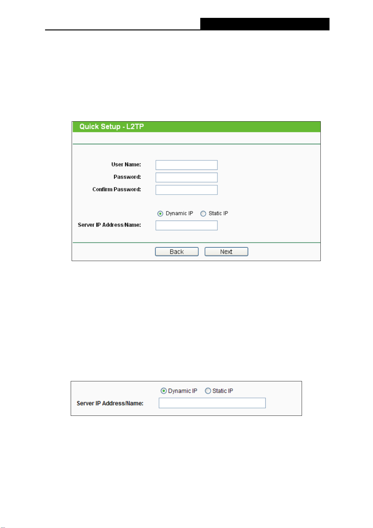
If the connection type is L2TP/Russian L2TP, the next screen will appear as shown in
Figure 3-17. Configure the following parameters and then click Next to continue.
Figure 3-17 Quick Setup – L2TP
User Name and Password - Enter the User Name and Password provided by your
ISP. These fields are case sensitive. If you have difficulty with this process, please
contact your ISP.
Confirm Password - Re-enter the password provided by your ISP to ensure the
Password you entered is correct.
Select Dynamic IP if none of IP Address, Subnet Mask, Gateway and DNS server address
are provided. Then you just need to enter server IP address or domain name provided by
your ISP.
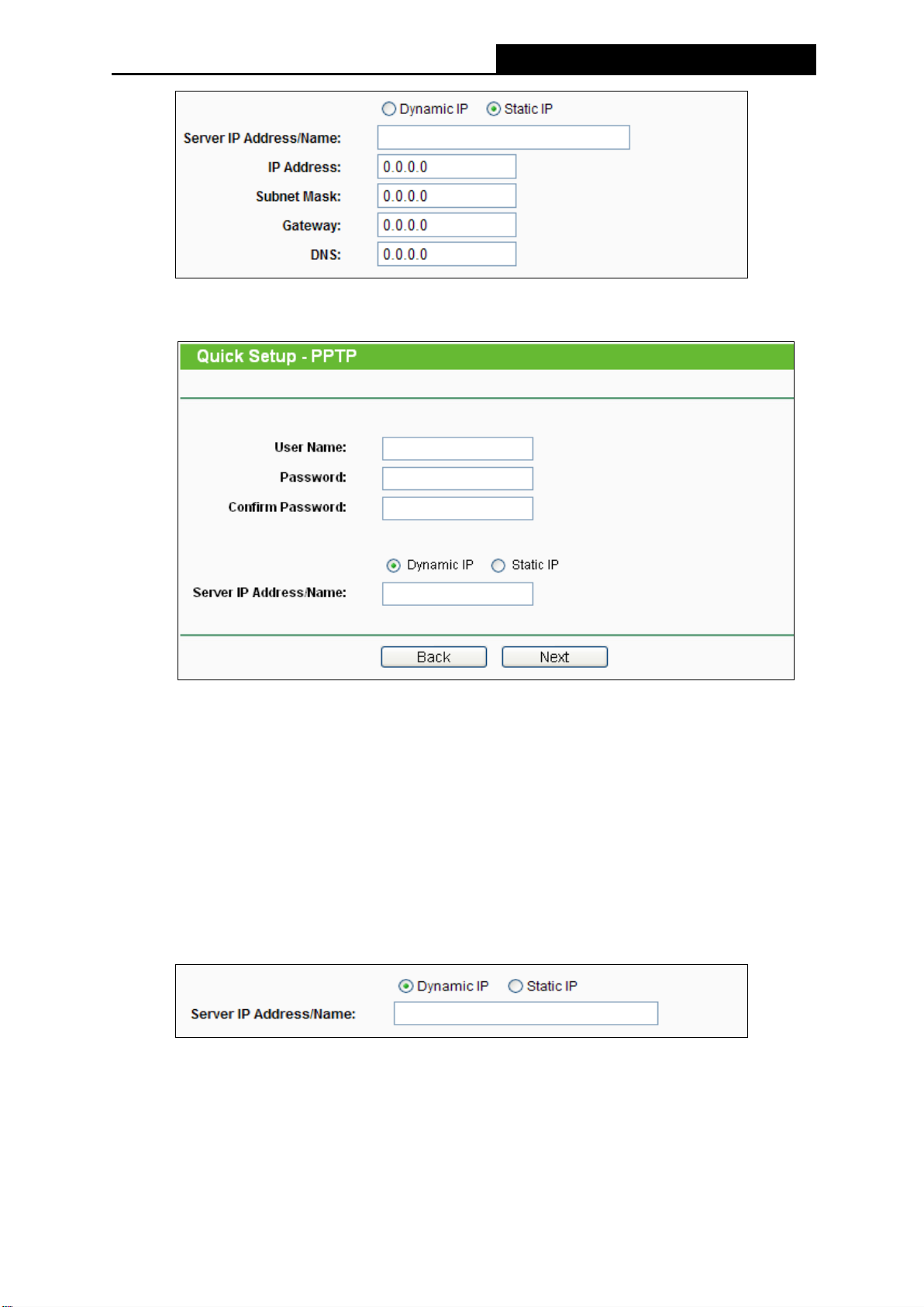
Select Static IP if the above parameters have been provided by your ISP. Then please enter
server IP address or domain name provided by your ISP, and also enter the corresponding
parameters.
-16-
Page 26
TL-MR6400
300Mbps Wireless N 4G LTE Router
If the connection type is PPTP/Russian PPTP, the next screen will appear as shown in
Figure 3-18. Configure the following parameters and then click Next to continue.
Figure 3-18 Quick Setup – PPTP
User Name and Password - Enter the User Name and Password provided by your
ISP. These fields are case sensitive. If you have difficulty with this process, please
contact your ISP.
Confirm Password - Re-enter the password provided by your ISP to ensure the
Password you entered is correct.
Select Dynamic IP if none of IP Address/ Subnet Mask/ Gateway and DNS server address
are provided. Then you just need to enter server IP address or domain name provided by
your ISP.
Select Static IP if the above parameters have been provided by your ISP. Then please enter
server IP address or domain name provided by your ISP, and also enter the corresponding
parameters.
-17-
Page 27
TL-MR6400
300Mbps Wireless N 4G LTE Router
10. Click Next to continue, the Wireless settings page will appear as shown in Figure 3-19.
Figure 3-19 Quick Setup – Wireless
Wireless Radio - Enable or disable the wireless function.
Wireless Network Name - Enter a string of up to 32 characters. The same name of
SSID (Service Set Identification) must be assigned to all wireless devices in your
network. Considering your wireless network security, the default SSID is set to be
TP-LINK_XXXX (XXXX indicates the last unique four numbers of each router’s MAC
address). This value is case-sensitive. For example, TEST is NOT the same as test.
Disable Security - The wireless security function can be enabled or disabled. If
disabled, the wireless stations will be able to connect the router without encryption. It
is recommended strongly that you choose one of following options to enable security.
WPA-PSK/WPA2-PSK – Select WPA-PSK/WPA2-PSK based on pre-shared
passphrase.
Wireless Password - You can enter ASCII or Hexadecimal characters.
For ASCII, the key can be made up of any numbers 0 to 9 and any letters A to Z,
the length should be between 8 and 63 characters.
-18-
Page 28
TL-MR6400
300Mbps Wireless N 4G LTE Router
For Hexadecimal, the key can be made up of any numbers 0 to 9 and letters A to
F, the length should be between 8 and 64 characters.
Please also note the key is case sensitive, this means that upper and lower case
keys will affect the outcome. It would also be a good idea to write down the key
and all related wireless security settings.
No Change - If you chose this option, wireless security configuration will not change!
These settings are only for basic wireless parameters. For advanced settings, please refer
to 4.8 Wirelss.
11. Click the Finish button to complete the Quick Setup.
Figure 3-20 Quick Setup – Finish
-19-
Page 29
TL-MR6400
300Mbps Wireless N 4G LTE Router
Chapter 4. Router Configuration-3G/4G Router Mode
This chapter will show each Web page's key functions and the configuration way on 3G/4G
Router Mode.
4.1 Login
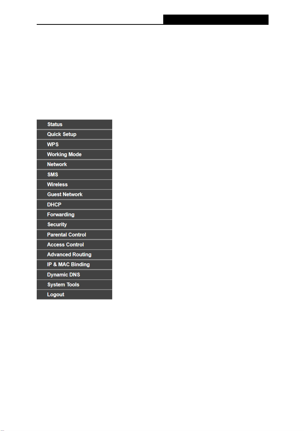
After your successful login, you will see the main menus on the left of the Web-based utility. On
the right, there are the corresponding explanations and instructions.
The detailed explanations for each Web page’s key function are listed below.
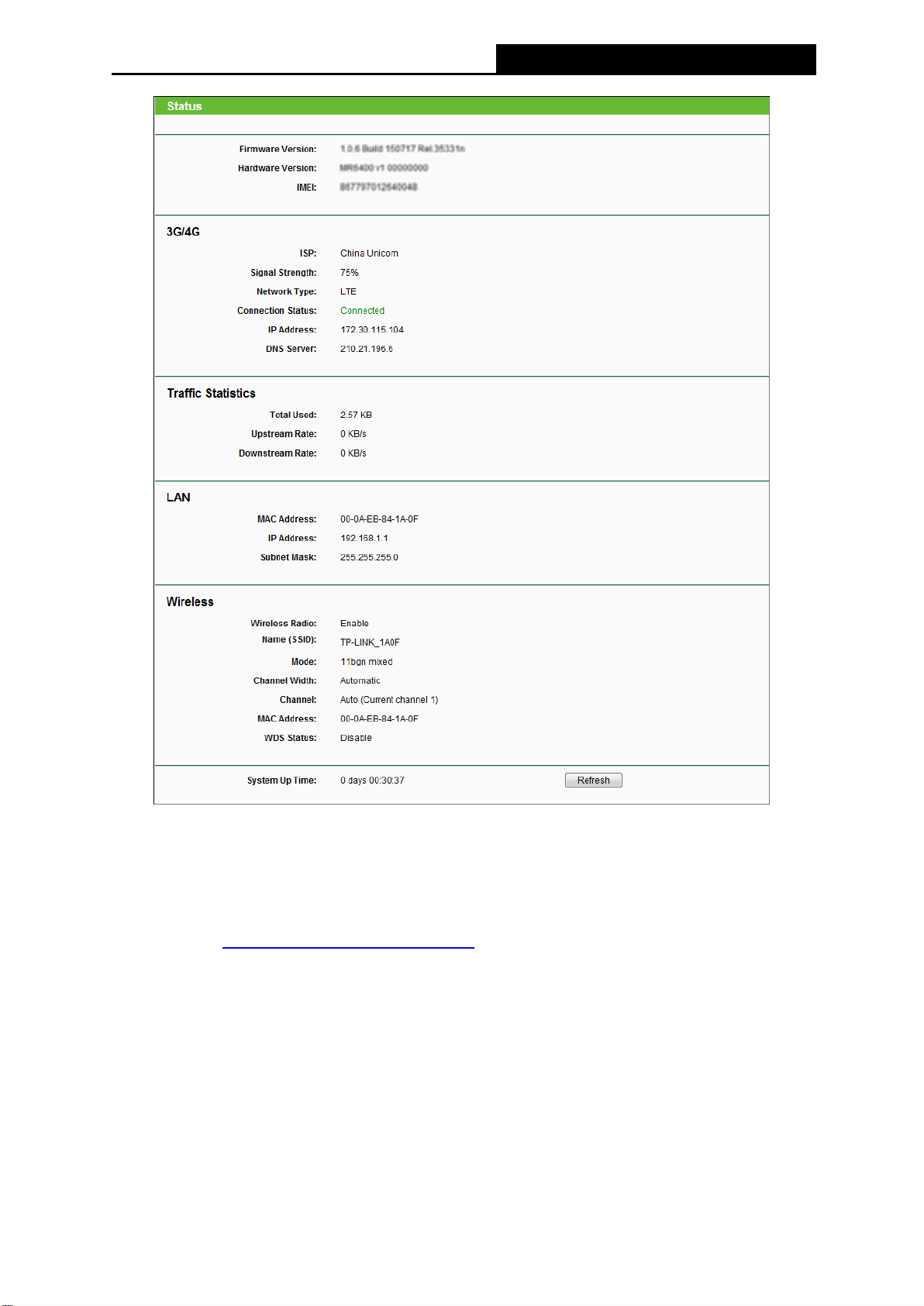
4.2 Status
The Status page provides the current status information about the device. All information is
read-only.
-20-
Page 30
TL-MR6400
300Mbps Wireless N 4G LTE Router
Figure 4-1 Router Status
4.3 Quick Setup
Please refer to Chapter 3: Quick Installation Guide.
4.4 WPS
This section will guide you to add a new wireless device to an existing network quickly by WPS
(Wi-Fi Protected Setup) function.
a). Choose menu “WPS”, and you will see the next screen.
-21-
Page 31

TL-MR6400
300Mbps Wireless N 4G LTE Router
Figure 4-2 WPS
WPS Status - Enable or disable the WPS function here.
Current PIN - The current value of this device's PIN displayed here. The default value can
be found in the label.
Restore PIN - Restore the PIN of this device to its default.
Gen New PIN - Click this button, and then you can get a new random value for this
device's PIN. You can ensure the network security by generating a new PIN.
Disable PIN of this device - You can disable the router’s PIN manually here. If the router
receives multiple failed attempts to authenticate an external registrar, this function will be
disabled automatically.
Add Device - You can add the new device to the existing network manually by clicking
this button.
b). To add a new device:
If the wireless adapter supports Wi-Fi Protected Setup (WPS), you can establish a wireless
connection between wireless adapter and Router using either Push Button Configuration (PBC)
method or PIN method.
Note:
To build a successful connection by WPS, you should also do the corresponding configuration
of the new device for WPS function meanwhile.
I. Use the Wi-Fi Protected Setup Button
Use this method if your client device has a WPS button.
Step 1: Press the WPS/RESET button on the back panel of the router.
You can also keep the default WPS Status as Enabled and click the Add Device
button in Figure 4-2, then Choose “Press the button of the new device in two
minutes” and click Connect. (Shown in the following figure)
-22-
Page 32

TL-MR6400
300Mbps Wireless N 4G LTE Router
Figure 4-3 Add A New Device
Step 2: Press and hold the WPS button of the client device directly. The WPS LED flashes for
two minutes during the Wi-Fi Protected Setup process.
Step 3: When the WPS LED is on, the client device has successfully connected to the router.
II. Enter the client device’s PIN on the router
Use this method if your client device does not have the WPS button, but has a Wi-Fi Protected
Setup PIN number.
Step 1: Keep the default WPS Status as Enabled and click the Add Device button in Figure
4-2, then the following screen will appear.
Figure 4-4 Add A New Device
Step 2: Enter the PIN number from the client device in the field on the WPS screen above.
Then click Connect button.
Step 3: “Connect successfully” will appear on the screen of Figure 4-4, which means the
client device has successfully connected to the router.
III. Enter the router’s PIN on your client device
Use this method if your client device asks for the router’s PIN number.
Step 1: On the client device, enter the PIN number listed on the router’s Wi-Fi Protected Setup
screen. (It is also labeled on the bottom of the router.)
Step 2: The Wi-Fi Protected Setup LED flashes for two minutes during the Wi-Fi Protected
Setup process.
Step 3: When the WPS LED is on, the client device has successfully connected to the router.
Step 4: Refer back to your client device or its documentation for further instructions.
Note:
1) The WPS LED on the router will light for five minutes if the device has been successfully
added to the network.
-23-
Page 33

TL-MR6400
300Mbps Wireless N 4G LTE Router
2) The WPS function cannot be configured if the wireless function of the router is disabled.
Please make sure the Wireless Function is enabled before configuring the WPS.
4.5 Working Mode
Figure 4-5 Working Mode
Standard Wireless Router - In this mode, this device will only use LAN/WAN port to
access Internet. The inner hosts can access Internet via 3 LAN ports or wireless.
3G/4G Router - In this mode, this device enables multiusers to share Internet via 3G/4G
modem. The LAN/WAN port acts the same as a LAN port while at 3G/4G Router mode.
Be sure to click the Save button to save your settings on this page.
Note:
The router will reboot automatically after you click the Save button.
4.6 Network
Figure 4-6 the Network menu
There are four submenus under the Network menu (shown in Figure 4-6): LTE Dial Up, LTE
Data Settings, PIN Management and LAN. Click any of them, and you will be able to configure
the corresponding function.
4.6.1 LTE Dial Up
Choose menu “Network → LTE Dial Up”, You can configure dial-up settings on this page.
-24-
Page 34

TL-MR6400
300Mbps Wireless N 4G LTE Router
Figure 4-7 Dial Up
Connection Status - Shows whether the Internet is connected or disconnected at present.
Mobile Data - It is enabled by default. You can disable it to prohibit Internet access.
Data Roaming - It is disabled by default. If disabled, data service is not allowed when
roaming. If enabled, data service is allowed when roaming, but may incur significant
roaming charges.
Network Mode - The device supports three modes of network connection - 4G Preferred,
4G Only, 3G Only. If your SIM card supports WCDMA, select 3G only; if your SIM card
supports LTE, select 4G Preferred or 4G only as you need.
Profile Name - A list of profile for you to select. After selecting one profile from the list, you
can further modify its parameters. Show the name of the profile you've selected here.
PDP Type - Select the type of your PDP (Packet Data Protocol).
APN Type - Select the type of your APN, either Dynamic or Static. If you select Dynamic,
the device will have dynamic APN, which does not need to be specified. If you select Static,
you can manually specify your APN.
APN - Access Point Name, provided by your ISP. You need to set APN only after selecting
the static APN type. You are recommended to keep the default value.
Username/Password - Enter the username and password provided by your ISP. These
fields are case-sensitive. You are recommended to keep the default value.
Authentication Type - Some ISPs need a specific authentication type, please confirm it
with your ISP or keep the default value.
None - No any authentication is needed.
PAP - Password Authentication Protocol. This protocol allows the device to establish
-25-
Page 35

TL-MR6400
300Mbps Wireless N 4G LTE Router
authentication with the peer using two handshakes. Select this option if the ISP
requires this authentication type.
CHAP - Challenge Handshake Authentication Protocol. This protocol allows the device
to establish authentication with the peer using three handshakes and checking the
peer identity periodically. Select this option if the ISP requires this authentication type.
Click the Delete button to delete a profile.
Click the Create button to create a new profile.
Click the Save button to save your settings.
4.6.2 LTE Data Settings
Choose menu “Network → LTE Data Settings”, You can configure data settings on this page.
Figure 4-8 LTE Data Settings
Total/Monthly Used - Total/Monthly data used. You can click Correct and input the actual
data amount to correct the data.
Data Limit - You can enable or disable the function of data limit. If enabled, you can set the
data quota and usage alert.
Total/Monthly Allowance - Set the allowed amount of total/monthly data. When data
usage exceeds the allowance, the device will disconnect Internet and display a message on
the screen asking whether to connect Internet.
Monthly Data Statistic - You can enable or disable the function of traffic data resetting.
Start Date - Enable the function and schedule a date, the data will reset to zero on the date.
If disabled, total data information is displayed. If enabled, monthly data information is
displayed.
Click the Save button to save your settings.
-26-
Page 36

TL-MR6400
300Mbps Wireless N 4G LTE Router
4.6.3 PIN Management
Choose menu “Network → PIN Management”, You can configure PIN code on this page.
Figure 4-9 PIN Management
SIM Card Status - Shows the status of your SIM card.
PIN Management - You can select whether to enable this function or not. Once the PIN
code function is enabled, every time you start the device with this SIM card inserted, you
need to enter the PIN code. But you can go to enable the auto-unlock PIN function, which
could save you this trouble.
PIN - Personal Identification Number of the SIM card. It consists of 4-8 digits.
PUK - PIN Unlocked Key. It consists of 8 digits.
Remaining Attempts - Shows how many attempts are left for you to try entering the PIN or
PUK code. You have 3 attempts at most for entering the PIN code and 10 attempts at most
for entering the PUK code.
Auto-unlock PIN upon Power-on - When the PIN code is required upon device restarting,
it will be validated automatically once. If validation failed, you need to enter the PIN code
on the Status page.
Note:
1. If the current status of PIN is disabled, you can select Enable and set a PIN code, and then
click Apply to make your settings take effect.
2. If the SIM current status is PIN enabled and verified, you can select Disable and enter the
current PIN code, or select Modify and set a new PIN code, and then click Apply to make
your settings take effect.
-27-
Page 37

TL-MR6400
300Mbps Wireless N 4G LTE Router
4.6.4 LAN
Choose menu “Network → LAN”, You can configure the IP parameters of LAN on this page.
Figure 4-10 LAN
MAC Address - The physical address of the LAN ports, as seen from the LAN. The value
cannot be changed.
IP Address - Enter the IP address of your Router in dotted-decimal notation (factory
default - 192.168.1.1).
Subnet Mask - An address code that determines the size of the network. Usually it is
255.255.255.0.
Note:
1. If you change the LAN IP address, you must use the new IP address to login to the router.
2. If the new LAN IP address you set is not in the same subnet with the previous one, the IP
Address pool in the DHCP server will be configured automatically, but the Virtual Server
and DMZ Host will not take effect until they are re-configured.
Click the Save button to save your settings.
4.7 SMS
Figure 4-11 Wireless menu
There are five submenus under the Wireless menu (shown in Figure 4-11): Inbox, New
Message, Outbox, Draft Box, SMS Settings. Click any of them, and you will be able to
configure the corresponding function.
-28-
Page 38

TL-MR6400
300Mbps Wireless N 4G LTE Router
4.7.1 Inbox
Figure 4-12 Inbox
Status - Show the status of message, either read or new.
Phone Number - Shows the phone number that sent this message.
Content - Click to unfold and read the detailed content of the message.
Received - Shows the time when the message was received.
Click the Refresh button to refresh the inbox, and get any new message.
Click the Delete button to delete the message(s) you select.
Click the Previous button to get messages of the previous page.
Click the Next button to get messages of the next page.
4.7.2 New Message
Phone Number - Enter the receiver's phone number.
Content - Text your message in this box. The message is limited to 160 letters or numbers,
any exceeding characters will be sent in the next message.
Figure 4-13 New Message
-29-
Page 39

TL-MR6400
300Mbps Wireless N 4G LTE Router
Click the Send button to send the message.
Click the Save button to save the message to the draft box.
4.7.3 Outbox
Figure 4-14 Outbox
Phone Number - Shows the phone number that this message was planned to be sent to.
Content - Click to unfold and read the detailed content of the message.
Sent - Shows the time when the message was sent.
Click the Refresh button to refresh the outbox.
Click the Delete button to delete the message(s) you select.
Click the Previous button to get messages of the previous page.
Click the Next button to get messages of the next page.
4.7.4 Draft Box
You can review the unsent saved messages on this page.
Figure 4-15 Draft Box
Phone Number - Shows the phone number that this message was planned to be sent to.
Content - Click to unfold and read the detailed content of the message, or for further
edition and delivery.
Click the Refresh button to refresh the drafts.
Click the Delete button to delete the message(s) you select.
Click the Previous button to get messages of the previous page.
-30-
Page 40

TL-MR6400
300Mbps Wireless N 4G LTE Router
Click the Next button to get messages of the next page.
4.7.5 SMS Settings
Figure 4-16 SMS Settings
Message Center - Disabled by default. Do not enable it unless you want to manually set
the message center number.
Message Center Number - When the message center is enabled, you can enter the
message center number of the local ISP. If you enter a wrong number, the message
function would be affected.
Click the Save button to save your settings.
4.8 Wireless
Figure 4-17 Wireless menu
There are five submenus under the Wireless menu (shown in Figure 4-17): Wireless Settings,
Wireless Security, Wireless MAC Filtering, Wireless Advanced and Wireless Statistics.
Click any of them, and you will be able to configure the corresponding function.
4.8.1 Wireless Settings
Choose menu “Wireless → Wireless Settings”, and then you can configure the basic settings
for the wireless network on this page.
-31-
Page 41

TL-MR6400
300Mbps Wireless N 4G LTE Router
Figure 4-18 Wireless Settings
Wireless Network Name - Enter a value of up to 32 characters. The same Name (SSID)
must be assigned to all wireless devices in your network.
Mode - Select transmission mode according to your wireless devices.
Channel Width - The bandwidth of the wireless channel.
Channel - This field determines which operating frequency will be used. It is not necessary
to change the wireless channel unless you notice interference problems with another
nearby access point. If you select auto, then AP will choose the best channel automatically.
Enable Wireless Router Radio - The wireless radio of the router can be enabled or
disabled to allow wireless stations access. If enabled, the wireless stations will be able to
access the router. Otherwise, wireless stations will not be able to access the router.
Enable SSID Broadcast - If you select the Enable SSID Broadcast checkbox, the wireless
router will broadcast its name (SSID) on the air.
Enable WDS Bridging - You can select this to enable WDS Bridging, with this function, the
router can bridge two or more WLANs. If this checkbox is selected, you had better make
sure the following settings are correct.
-32-
Page 42

TL-MR6400
300Mbps Wireless N 4G LTE Router
SSID (to be bridged) - The SSID of the AP your Router is going to connect to as a
client. You can also use the survey function to select the SSID to join.
BSSID (to be bridged) - The BSSID of the AP your Router is going to connect to as a
client. You can also use the survey function to select the BSSID to join.
Survey - Click this button, you can search the AP which runs in the current channel.
WDS Mode - This field determines which WDS Mode will be used. It is not necessary
to change the WDS Mode unless you notice network communication problems with
root AP. If you select Auto, then Router will choose the appropriate WDS Mode
automatically.
Key type - This option should be chosen according to the AP's security configuration.
It is recommended that the security type is the same as your AP's security type
WEP Index - This option should be chosen if the key type is WEP (ASCII) or WEP
(HEX).It indicates the index of the WEP key.
Auth Type - This option should be chosen if the key type is WEP (ASCII) or WEP
(HEX).It indicates the authorization type of the Root AP.
Password - If the AP your Router is going to connect needs password, you need to
fill the password in this blank.
4.8.2 Wireless Security
Choose menu “Wireless → Wireless Security”, and then you can configure the security
settings of your wireless network.
-33-
Page 43

TL-MR6400
300Mbps Wireless N 4G LTE Router
Figure 4-19
Disable Security- If you do not want to use wireless security, select this check box, but it’s
strongly recommended to choose one of the following modes to enable security.
WPA/WPA2 – Personal (Recommended) - It’s the WPA/WPA2 authentication type
based on pre-shared passphrase.
Version - you can choose the version of the WPA-PSK security on the drop-down list.
The default setting is Automatic, which can select WPA-PSK (Pre-shared key of WPA)
or WPA2-PSK (Pre-shared key of WPA2) automatically based on the wireless station's
capability and request.
Encryption - you can select either Automatic, or TKIP or AES as Encryption.
Note:
If you check the WPA/WPA2 – Personal (Recommended) radio button and choose TKIP
encryption, you will find a notice in red as shown in Figure 4-20.
-34-
Page 44

TL-MR6400
300Mbps Wireless N 4G LTE Router
Figure 4-20
Wireless Password - You can enter ASCII or Hexadecimal characters. For Hexadecimal,
the length should be between 8 and 64 characters; for ASCII, the length should be
between 8 and 63 characters.
Group Key Update Period - Specify the group key update interval in seconds. The
value should be 30 or above. Enter 0 to disable the update.
Be sure to click the Save button to save your settings on this page.
WPA /WPA2 - Enterprise - It’s based on Radius Server.
Version - you can choose the version of the WPA security on the pull-down list. The
default setting is Automatic, which can select WPA (Wi-Fi Protected Access) or WPA2
(WPA version 2) automatically based on the wireless station's capability and request.
Encryption - You can select either Automatic, or TKIP or AES.
Note:
If you check the WPA/WPA2 - Enterprise radio button and choose TKIP encryption, you
will find a notice in red as shown in Figure 4-21.
Figure 4-21
Radius Server IP - Enter the IP address of the Radius Server.
Radius Port - Enter the port that radius service used.
Radius Password - Enter the password for the Radius Server.
Group Key Update Period - Specify the group key update interval in seconds. The
value should be 30 or above. Enter 0 to disable the update.
-35-
Page 45

TL-MR6400
300Mbps Wireless N 4G LTE Router
WEP - It is based on the IEEE 802.11 standard. If you select this check box, you will find a
notice in red as show in Figure 4-22.
Figure 4-22
Type - you can choose the type for the WEP security on the pull-down list. The default
setting is Automatic, which can select Open System or Shared Key authentication type
automatically based on the wireless station's capability and request.
WEP Key Format - Hexadecimal and ASCII formats are provided. Hexadecimal
format stands for any combination of hexadecimal digits (0-9, a-f, A-F) in the specified
length. ASCII format stands for any combination of keyboard characters in the specified
length.
WEP Key- Select which of the four keys will be used and enter the matching WEP key
that you create. Make sure these values are identical on all wireless stations in your
network.
Key Type - You can select the WEP key length (64bit, or 128bit, or 152bit.) for
encryption. "Disabled" means this WEP key entry is invalid.
64bit - You can enter 10 hexadecimal digits (any combination of 0-9, a-f, A-F, null key is
not permitted) or 5 ASCII characters.
128bit - You can enter 26 hexadecimal digits (any combination of 0-9, a-f, A-F, null key is
not permitted) or 13 ASCII characters.
152bit - You can enter 32 hexadecimal digits (any combination of 0-9, a-f, A-F, null key is
not permitted) or 16 ASCII characters.
Note:
If you do not set the key, the wireless security function is still disabled even if you have
selected Shared Key as Authentication Type.
-36-
Page 46

TL-MR6400
300Mbps Wireless N 4G LTE Router
4.8.3 Wireless MAC Filtering
Choose menu “Wireless → MAC Filtering”, and then you can control the wireless access by
configuring the Wireless MAC Address Filtering function, shown in Figure 4-23.
Figure 4-23 Wireless MAC address Filtering
To filter wireless users by MAC Address, click Enable. The default setting is Disable.
MAC Address - The wireless station's MAC address that you want to filter.
Status - The status of this entry is either Enabled or Disabled.
Description - A simple description of the wireless station.
To Add a Wireless MAC Address filtering entry, click the Add New… button. The "Add or
Modify Wireless MAC Address Filtering entry" page will appear as shown in Figure 4-24:
Figure 4-24 Add or Modify Wireless MAC Address Filtering entry
To add a MAC Address Filtering entry, follow these instructions:
1. Enter the appropriate MAC Address into the MAC Address field. The format of the MAC
Address is XX-XX-XX-XX-XX-XX (X is any hexadecimal digit). For example:
00-0A-EB-00-07-8A.
-37-
Page 47

TL-MR6400
300Mbps Wireless N 4G LTE Router
2. Enter a simple description of the wireless station in the Description field. For example:
Wireless station A.
3. Status - Select Enabled or Disabled for this entry on the Status drop-down list.
4. Click the Save button to save this entry.
To modify an existing entry:
1. Click the Modify in the entry you want to modify.
2. Modify the information.
3. Click the Save button.
Click the Delete in the entry you want to delete to delete an existing entry.
Click the Enable All button to make all entries enabled.
Click the Disable All button to make all entries disabled.
Click the Delete All button to delete all entries.
Click the Next button to go to the next page.
Click the Previous button to return to the previous page.
For example: If you desire that the wireless station A with MAC address 00-0A-EB-00-07-8A
and the wireless station B with MAC address 00-0A-EB-00-23-11 are able to access the router,
but all the other wireless stations cannot access the router, you can configure the Wireless
MAC Address Filtering list by following these steps:
1. Click the Enable button to enable this function.
2. Select the radio button: Allow the stations not specified by any enabled entries in the
list to access for Filtering Rules.
3. Delete all or disable all entries if there are any entries already.
4. Click the Add New... button and enter the MAC address 00-0A-EB-00-07-8A
/00-0A-EB-00-23-11 in the MAC Address field, then enter wireless station A/B in the
Description field, while select Enabled in the Status drop-down list. Finally, click the Save
button.
The filtering rules that configured should be similar to the following list:
-38-
Page 48

TL-MR6400
300Mbps Wireless N 4G LTE Router
4.8.4 Wireless Advanced
Choose menu “Wireless → Wireless Advanced”, and then you can configure the advanced
settings of your wireless network.
Figure 4-25 Wireless Advanced
Transmit Power - Here you can specify the transmit power of this device. You can
select High, Middle or Low which you would like. High is the default setting and is
recommended.
Beacon Interval - The beacons are the packets sent by this device to synchronize a
wireless network. Beacon Interval value determines the time interval of the beacons.
You can specify a value between 40-1000 milliseconds. The default value is 100.
RTS Threshold - Here you can specify the RTS (Request to Send) Threshold. If the
packet is larger than the specified RTS Threshold size, this device will send RTS
frames to a particular receiving station and negotiate the sending of a data frame. The
default value is 2346.
Fragmentation Threshold - This value is the maximum size determining whether
packets will be fragmented. Setting the Fragmentation Threshold too low may result in
poor network performance since excessive packets. 2346 is the default setting and is
recommended. (This value for the mode of 11N series can not be changed)
-39-
Page 49

TL-MR6400
300Mbps Wireless N 4G LTE Router
DTIM Interval - This value determines the interval of the Delivery Traffic Indication
Message (DTIM). You can specify the value between 1-255 Beacon Intervals. The
default value is 1, which indicates the DTIM Interval is the same as Beacon Interval.
Enable WMM - WMM function can guarantee the packets with high- priority messages
being transmitted preferentially. It is strongly recommended enabled.
Enable Short GI - This function is recommended for it will increase the data capacity
by reducing the guard interval time.
Enable AP Isolation - Isolate all connected wireless stations so that wireless stations
cannot access each other through WLAN. This function will be disabled if WDS/Bridge
is enabled.
Note:
If you are not familiar with the setting items in this page, it's strongly recommended to keep
the provided default values; otherwise it may result in lower wireless network performance.
4.8.5 Wireless Statistics
Choose menu “Wireless → Wireless Statistics”, and then you can see the MAC Address,
Current Status, Received Packets and Sent Packets for each connected wireless station.
Figure 4-26 The router attached wireless stations
MAC Address - The connected wireless station's MAC address.
Current Status - The connected wireless station's running status, one of STA-AUTH /
STA-ASSOC / STA-JOINED / WPA / WPA-PSK / WPA2 / WPA2-PSK / AP-UP /
AP-DOWN / Disconnected.
Received Packets - Packets received by the station.
Sent Packets - Packets sent by the station.
Configure - The button is used for loading the item to the Wireless MAC Filtering list.
Deny: if the Wireless MAC Filtering function enable, deny the station to access.
Allow: if the Wireless MAC Filtering function enable, allow the station to access.
-40-
Page 50

TL-MR6400
300Mbps Wireless N 4G LTE Router
You cannot change any of the values on this page. To update this page and to show the
current connected wireless stations, click on the Refresh button.
If the numbers of connected wireless stations go beyond one page, click the Next button to go
to the next page and click the Previous button to return to the previous page.
Note:
This page will be refreshed automatically every 5 seconds.
4.9 Guest Network
Figure 4-27 The Guest Network menu
There are two submenus under the Guest Network menu (shown in Figure 4-27): Wireless
Settings and Wireless Statistics. Click any of them, and you will be able to configure the
corresponding function.
4.9.1 Wireless Settings
Choose menu “Guest Network → Wireless Settings”, you can configure the basic settings
for the Guest network on this page.
Allow Guest To Access My Local Network - If enabled, guests can communicate with
hosts.
Figure 4-28 Wireless Setting
-41-
Page 51

TL-MR6400
300Mbps Wireless N 4G LTE Router
Guest Network - Enabled or disable the Guest Network function here.
Network Name - Enter a value of up to 32 characters. The same Name (SSID) must be
assigned to all wireless devices in your Guest Network.
Wireless Security - You can configure the security of Guest Network here.
Access Time - During the time the wireless stations could accessing the router.
4.9.2 Wireless Statistics
Choose menu “Guest Network → Wireless Statistics”, and then you can see the MAC
Address, Current Status, Received Packets and Sent Packets for each connected wireless
station.
Figure 4-29 Guest Network – Wireless Statistics
MAC Address - The connected wireless station's MAC address.
Current Status - The connected wireless station's running status, one of STA-AUTH /
STA-ASSOC / STA-JOINED / WPA / WPA-PSK / WPA2 / WPA2-PSK / AP-UP /
AP-DOWN / Disconnected.
Received Packets - Packets received by the station.
Sent Packets - Packets sent by the station.
Configure - The button is used for loading the item to the Wireless MAC Filtering list.
Deny: if the Wireless MAC Filtering function enable, deny the station to access.
Allow: if the Wireless MAC Filtering function enable, allow the station to access.
You cannot change any of the values on this page. To update this page and to show the
current connected wireless stations, click the Refresh button.
If the numbers of connected wireless stations go beyond one page, click the Next button to go
to the next page and click the Previous button to return to the previous page.
Note:
This page will be refreshed automatically every 5 seconds.
-42-
Page 52

TL-MR6400
300Mbps Wireless N 4G LTE Router
4.10 DHCP
Figure 4-30 The DHCP menu
There are three submenus under the DHCP menu (shown in Figure 4-30): DHCP Settings,
DHCP Client List and Address Reservation. Click any of them, and you will be able to
configure the corresponding function.
4.10.1 DHCP Settings
Choose menu “DHCP → DHCP Settings”, and then you can configure the DHCP Server on
the page (shown in Figure 4-31).The router is set up by default as a DHCP (Dynamic Host
Configuration Protocol) server, which provides the TCP/IP configuration for all the PC(s) that
are connected to the router on the LAN.
Figure 4-31 DHCP Settings
DHCP Server - Enable or Disable the DHCP server. If you disable the Server, you must
have another DHCP server within your network or else you must configure the computer
manually.
Start IP Address - Specify an IP address for the DHCP Server to start with when
assigning IP addresses. 192.168.1.100 is the default start address.
End IP Address - Specify an IP address for the DHCP Server to end with when assigning
IP addresses. 192.168.1.199 is the default end address.
-43-
Page 53

TL-MR6400
300Mbps Wireless N 4G LTE Router
Address Lease Time - The Address Lease Time is the amount of time a network user
will be allowed connection to the router with their current dynamic IP Address. Enter the
amount of time in minutes and the user will be "leased" this dynamic IP Address. After the
time is up, the user will be automatically assigned a new dynamic IP address. The range
of the time is 1 ~ 2880 minutes. The default value is 120 minutes.
Default Gateway - (Optional) Suggest to input the IP address of the LAN port of the router,
default value is 192.168.1.1.
Default Domain - (Optional) Input the domain name of your network.
Primary DNS - (Optional) Input the DNS IP address provided by your ISP. Or consult your
ISP.
Secondary DNS - (Optional) Input the IP address of another DNS server if your ISP
provides two DNS servers.
Note:
To use the DHCP server function of the router, you must configure all computers on the LAN as
"Obtain an IP address automatically" mode. This function will take effect until this device reboots.
Click Save to save the changes.
4.10.2 DHCP Client List
Choose menu “DHCP → DHCP Client List”, and then you can view the information about the
clients attached to the router in the next screen (shown in Figure 4-32).
Figure 4-32 DHCP Client List
ID - The index of the DHCP Client.
Client Name - The name of the DHCP client.
MAC Address - The MAC address of the DHCP client.
Assigned IP - The IP address that the router has allocated to the DHCP client.
Lease Time - The time of the DHCP client leased.
You cannot change any of the values on this page. To update this page and to show the
current connected devices, click on the Refresh button.
-44-
Page 54

TL-MR6400
300Mbps Wireless N 4G LTE Router
4.10.3 Address Reservation
Choose menu “DHCP → Address Reservation”, and then you can view and add a reserved
address for clients via the next screen (shown in Figure 4-33). When you specify a reserved IP
address for a PC on the LAN, that PC will always receive the same IP address each time when
it accesses the DHCP server. Reserved IP addresses should be assigned to the servers that
require permanent IP settings.
Figure 4-33 Address Reservation
MAC Address - The MAC address of the PC for which you want to reserve IP address.
Reserved IP Address - The IP address of the router reserved.
Status - The status of this entry is either Enabled or Disabled.
To Reserve IP addresses:
1. Click the Add New … button. (Pop-up Figure 4-34)
Figure 4-34 Add or Modify an Address Reservation Entry
2. Enter the MAC Address (The format for the MAC Address is XX-XX-XX-XX-XX-XX) and
the IP address in dotted-decimal notation of the computer you wish to add.
3. Click the Save button when finished.
To modify an existing entry:
1. Click the Modify in the entry you want to modify.
-45-
Page 55

TL-MR6400
300Mbps Wireless N 4G LTE Router
2. Modify the information.
3. Click the Save button.
Click the Delete in the entry you want to delete to delete an existing entry.
Click the Enable/ Disable All button to make all entries enabled/disabled.
Click the Delete All button to delete all entries.
Click the Next button to go to the next page and click the Previous button to return to the
previous page.
4.11 Forwarding
Figure 4-35 The Forwarding menu
There are four submenus under the Forwarding menu (shown in Figure 4-35): Virtual Servers,
Port Triggering, DMZ and UPnP. Click any of them, and you will be able to configure the
corresponding function.
4.11.1 Virtual Servers
Choose menu “Forwarding → Virtual Servers”, you can view and add virtual servers in the
next screen (shown in Figure 4-36). Virtual servers can be used for setting up public services
on your LAN. A virtual server is defined as a service port, and all requests from Internet to this
service port will be redirected to the computer specified by the server IP. Any PC that was
used for a virtual server must have a static or reserved IP address because its IP address may
change when using the DHCP function.
Service Port - The numbers of External Service Ports. You can enter a service port or a
range of service ports (the format is XXX - YYY, XXX is Start port, YYY is End port).
Figure 4-36 Virtual Servers
-46-
Page 56

TL-MR6400
300Mbps Wireless N 4G LTE Router
Internal Port - The Internal Service Port number of the PC running the service application.
You can enter a specific port number, or leave it blank if the Internal Port is the same as
the Service Port.
IP Address - The IP Address of the PC providing the service application.
Protocol - The protocol used for this application, either TCP, UDP, or All (all protocols
supported by the router).
Status - The status of this entry, "Enabled" means the virtual server entry is enabled. The
status of this entry is either Enabled or Disabled.
To setup a virtual server entry:
1. Click the Add New… button. (pop-up Figure 4-37)
Figure 4-37 Add or Modify a Virtual Server Entry
2. Select the service you want to use from the Common Service Port list. If the Common
Service Port list does not have the service that you want to use, type the number of the
service port or service port range in the Service Port box.
3. Type the IP Address of the computer in the IP Address box.
4. Select the protocol used for this application, either TCP or UDP, or All.
5. Select the Enable check box to enable the virtual server.
6. Click the Save button.
Note:
It is possible that you have a computer or server that has more than one type of available service.
If so, select another service, and type the same IP address for that computer or server.
To modify an existing entry:
1. Click the Modify in the entry you want to modify.
2. Modify the information.
3. Click the Save button.
Click the Delete in the entry you want to delete to delete an existing entry.
-47-
Page 57

TL-MR6400
300Mbps Wireless N 4G LTE Router
Click the Enable/ Disable All button to make all entries enabled/ disabled.
Click the Delete All button to delete all entries.
Click the Next button to go to the next page and click the Previous button to return the previous
page.
Note:
If you set the service port of the virtual server as 80, you must set the Web management port on
Security → Remote Management page to be any other value except 80 such as 8080.
Otherwise there will be a conflict to disable the virtual server.
4.11.2 Port Triggering
Choose menu “Forwarding → Port Triggering”, you can view and add port triggering in the
next screen (shown in Figure 4-38). Some applications require multiple connections, like
Internet games, video conferencing, Internet telephoning and so on. Port Triggering is used for
some of these applications that cannot work with a pure NAT Router.
Figure 4-38 Port Triggering
Once the router is configured, the operation is as follows:
1. A local host makes an outgoing connection using a destination port number defined in the
Trigger Port field.
2. The router records this connection, opens the incoming port or ports associated with this
entry in the Port Triggering table, and associates them with the local host.
3. When necessary the external host will be able to connect to the local host using one of the
ports defined in the Incoming Ports field.
Trigger Port - The port for outgoing traffic. An outgoing connection using this port will
"Trigger" this rule.
Trigger Protocol - The protocol used for Trigger Ports, either TCP, UDP, or All (all
protocols supported by the router).
Incoming Port - The port or port range used by the remote system when it responds to the
outgoing request. A response using one of these ports will be forwarded to the PC that
triggered this rule. You can input at most 5 groups of ports (or port section). Every group of
ports must be set apart with ",". For example, 2000-2038, 2050-2051, 2085, 3010-3030.
Incoming Protocol - The protocol used for Incoming Ports Range, either TCP or UDP, or
ALL (all protocols supported by the router).
-48-
Page 58

TL-MR6400
300Mbps Wireless N 4G LTE Router
Status - The status of this entry is either Enabled or Disabled.
To add a new rule, follow the steps below.
1. Click the Add New… button, the next screen will pop-up as shown in Figure 4-39.
Figure 4-39 Add or Modify a Triggering Entry
2. Select a common application from the Common Applications drop-down list, then the
Trigger Port field and the Incoming Ports field will be automatically filled. If the Common
Applications do not have the application you need, enter the Trigger Port and the
Incoming Ports manually.
3. Select the protocol used for Trigger Port from the Trigger Protocol drop-down list, either
TCP, UDP, or All.
4. Select the protocol used for Incoming Ports from the Incoming Protocol drop-down list,
either TCP or UDP, or All.
5. Select Enable in Status field.
6. Click the Save button to save the new rule.
To modify an existing entry:
1. Click the Modify in the entry you want to modify.
2. Modify the information.
3. Click the Save button.
Click the Delete in the entry you want to delete to delete an existing entry.
Click the Enable All button to make all entries enabled
Click the Disable All button to make all entries disabled.
Click the Delete All button to delete all entries.
Click the Next button to go to the next page and click the Previous button to return the previous
page.
-49-
Page 59

TL-MR6400
300Mbps Wireless N 4G LTE Router
Note:
1) When the trigger connection is released, the according opening ports will be closed.
2) Each rule can only be used by one host on the LAN at a time. The trigger connection of
other hosts on the LAN will be refused.
3) Incoming Port Ranges cannot overlap each other.
4.11.3 DMZ
Choose menu “Forwarding → DMZ”, you can view and configure DMZ host in the screen
(shown in Figure 4-40). The DMZ host feature allows one local host to be exposed to the
Internet for a special-purpose service such as Internet gaming or video conferencing. The
router forwards packets of all services to the DMZ host. Any PC that is set to be DMZ host must
have its DHCP client function disabled and should have a new static IP address assigned to it
because its IP Address may change when using the DHCP function.
Figure 4-40 DMZ
To assign a computer or server to be a DMZ server:
1. Click the Enable radio button
2. Enter the local host IP Address in the DMZ Host IP Address field
3. Click the Save button.
4.11.4 UPnP
Choose menu “Forwarding → UPnP”, you can view the information about UPnP(Universal
Plug and Play) in the screen (shown in Figure 4-41).The UPnP feature allows the devices, such
as Internet computers, to access the local host resources or devices as needed. UPnP devices
can be automatically discovered by the UPnP service application on the LAN.
-50-
Page 60

TL-MR6400
300Mbps Wireless N 4G LTE Router
Figure 4-41 UPnP Setting
Current UPnP Status - UPnP can be enabled or disabled by clicking the Enable or
Disable button. This feature is enabled by default.
Current UPnP Settings List - This table displays the current UPnP information.
App Description -The description provided by the application in the UPnP request
External Port - External port, which the router opened for the application.
Protocol - Shows which type of protocol is opened.
Internal Port - Internal port, which the router opened for local host.
IP Address - The UPnP device that is currently accessing the router.
Status - The port’s status displayed here. “Enabled” means that port is still active.
Otherwise, the port is inactive.
Click the Enable button to enable UPnP.
Click the Disable button to disable UPnP.
Click Refresh to update the Current UPnP Settings List.
4.12 Security
Figure 4-42 The Security menu
There are three submenus under the Security menu as shown in Figure 4-42: Basic Security,
Local Management and Remote Management. Click any of them, and you will be able to
configure the corresponding function.
4.12.1 Basic Security
Choose menu “Security → Basic Security”, you can configure the basic security in the
screen as shown in Figure 4-43.
-51-
Page 61

TL-MR6400
300Mbps Wireless N 4G LTE Router
Figure 4-43 Basic Security
Firewall - A firewall protects your network from the outside world. Here you can enable or
disable the router’s firewall.
SPI Firewall - SPI (Stateful Packet Inspection, also known as dynamic packet filtering)
helps to prevent cyber attacks by tracking more state per session. It validates that the
traffic passing through the session conforms to the protocol. SPI Firewall is enabled by
factory default. If you want all the computers on the LAN exposed to the outside world,
you can disable it.
VPN - VPN Passthrough must be enabled if you want to allow VPN tunnels using IPSec,
PPTP, or L2TP protocols to pass through the router’s firewall.
PPTP Passthrough - PPTP Passthrough. Point-to-Point Tunneling Protocol (PPTP)
allows the Point-to-Point Protocol (PPP) to be tunneled through an IP network. To
allow PPTP tunnels to pass through the router, click Enable.
L2TP Passthrough - Layer Two Tunneling Protocol (L2TP) is the method used to
enable Point-to-Point sessions via the Internet on the Layer Two level. To allow L2TP
tunnels to pass through the router, click Enable.
IPSec Passthrough - Internet Protocol security (IPSec) is a suite of protocols for
ensuring private, secure communications over Internet Protocol (IP) networks, through
the use of cryptographic security services. To allow IPSec tunnels to pass through the
router, click Enable.
ALG - It is recommended to enable Application Layer Gateway (ALG) because ALG allows
customized Network Address Translation (NAT) traversal filters to be plugged into the
-52-
Page 62

TL-MR6400
300Mbps Wireless N 4G LTE Router
gateway to support address and port translation for certain application layer "control/data"
protocols such as FTP, TFTP, H323 etc.
FTP ALG - To allow FTP clients and servers to transfer data across NAT, click Enable.
TFTP ALG - To allow TFTP clients and servers to transfer data across NAT, click
Enable.
H323 ALG - To allow Microsoft NetMeeting clients to communicate across NAT, click
Enable.
RTSP ALG - To allow some media player clients to communicate with some streaming
media servers across NAT, click Enable.
SIP ALG - To allow some multimedia clients to communicate across NAT, click
Enable.
Click the Save button to save your settings.
4.12.2 Local Management
Choose menu “Security → Local Management”, you can configure the management rule in
the screen as shown in Figure 4-44. The management feature allows you to deny LAN
computers from accessing the router.
Figure 4-44 Local Management
By default, the radio button All the PCs on the LAN are allowed to access the Router's
Web-Based Utility is selected. If you want to allow PCs with specific MAC Addresses to access
the Setup page of the router's Web-Based Utility locally, from inside the network, click the radio
button Only the PCs listed can browse the built-in web pages to perform Administrator
tasks, and then enter each MAC Address in a separate field. The format for the MAC Address
is XX-XX-XX-XX-XX-XX (X is any hexadecimal digit). Only the PCs with the MAC address listed
can use the password to browse the built-in web pages to perform Administrator tasks and all
the others will be blocked.
After click the Add button, your PC's MAC Address will be placed in the Control List above.
Click the Save button to save your settings.
-53-
Page 63

TL-MR6400
300Mbps Wireless N 4G LTE Router
Note:
If your PC is blocked and you want to access the router again, press and hold down the
WPS/RESET button on the rear panel of the router until the Power LED starts flashing to reset
the router's factory defaults in the router's Web-Based Utility.
4.12.3 Remote Management
Choose menu “Security → Remote Management”, you can configure the Remote
Management function in the screen as shown in Figure 4-45. This feature allows you to manage
your Router from a remote location via the Internet.
Figure 4-45 Remote Management
Web Management Port - Web browser access normally uses the standard HTTP service
port 80. This Router's default remote management web port number is 80. For greater
security, you can change the remote management web port to a custom port by entering
that number in the box provided. Choose a number between 1 and 65535 but do not use
the number of any common service port.
Remote Management IP Address - This is the current address you will use when
accessing your Router from the Internet. This function is disabled when the IP address is
set to the default value of 0.0.0.0. To enable this function change 0.0.0.0 to a valid IP
address. If set to 255.255.255.255, then all the hosts can access the router from internet.
To access the router, you should enter your Router's WAN IP address into your browser's
address (in IE) or location (in Netscape) box, followed by a colon and the custom port number
you set in the Web Management Port box. For example, if your Router's WAN address is
202.96.12.8 and you use port number 8080, enter http://202.96.12.8:8080 in your browser. You
will be asked for the router's password. After successfully entering the password, you will be
able to access the router's web-based utility.
Note:
1) Some ports are commonly used for other services (Such as 21, 25, 110, 119, 139, 145
and 445). For security reasons, these ports will be restricted.
2) Be sure to change the router's default password to a secure password.
3) If the web management port conflicts with the one used for a Virtual Server entry, the
entry will be automatically disabled after the setting is saved.
-54-
Page 64

TL-MR6400
300Mbps Wireless N 4G LTE Router
4.13 Parental Control
Choose menu “Parental Control”, and you can configure the parental control in the screen as
shown in Figure 4-46. The Parental Control function can be used to control the internet activities
of the child, limit the child to access certain websites and restrict the time of surfing. On this
page, you can create the rule.
Figure 4-46 Parental Control Settings
Parental Control - Check Enable if you want this function to take effect, otherwise check
Disable.
MAC Address of Parental PC - In this field, enter the MAC address of the controlling PC,
or you can make use of the Copy To Above button below.
MAC Address of Your PC - This field displays the MAC address of the PC that is
managing this Router. If the MAC Address of your adapter is registered, you can click the
Copy To Above button to fill this address to the MAC Address of Parental PC field above.
Website Description - Description of the allowed website for the PC controlled.
Schedule - The time period allowed for the PC controlled to access the Internet. For
detailed information, please go to Access Control → Schedule.
Modify - Here you can edit or delete an existing entry.
To add a new entry, please follow the steps below.
1. Click the Add New… button and the next screen will pop-up as shown in Figure 4-47.
-55-
Page 65

TL-MR6400
300Mbps Wireless N 4G LTE Router
Figure 4-47 Add or Modify Parental Control Entry
2. Enter the MAC address of the PC (e.g. 00-11-22-33-44-AA) you’d like to control in the MAC
Address of Children's PC field. Or you can choose the MAC address from the All Address
in Current LAN drop-down list.
3. Give a description (e.g. Allow TP-LINK) for the website allowed to be accessed in the
Website Description field.
4. Enter the allowed domain name of the website, either the full name or the keywords (e.g.
tp-link) in the Allowed Website Name field. Any domain name with keywords in it
(www.tp-link.com, www.tp-link.com.cn) will be allowed.
5. Select from the Effective Time drop-down list the schedule (e.g. Schedule_1) you want the
entry to take effect. If there are not suitable schedules for you, click the Schedule in red
below to go to the Advance Schedule Settings page and create the schedule you need.
6. In the Status field, you can select Enabled or Disabled to enable or disable your entry.
7. Click the Save button.
Click the Enable All button to enable all the rules in the list.
Click the Disable All button to disable all the rules in the list.
Click the Delete All button to delete all the entries in the table.
Click the Next button to go to the next page, or click the Previous button return to the previous
page.
For example: If you desire that the child PC with MAC address 00-11-22-33-44-AA can access
www.tp-link.com on Saturday only while the parent PC with MAC address 00-11-22-33-44-BB is
without any restriction, you should follow the settings below.
-56-
Page 66

TL-MR6400
300Mbps Wireless N 4G LTE Router
1. Click “Parental Control” menu on the left to enter the Parental Control Settings page.
Check Enable and enter the MAC address 00-11-22-33-44-BB in the MAC Address of
Parental PC field, then click Save.
2. Click “Access Control → Schedule” on the left to enter the Schedule Settings page. Click
Add New... button to create a new schedule with Schedule Description is Schedule_1, Day
is Sat and Time is all day-24 hours, then click Save.
3. Click “Parental Control” menu on the left to go back to the Add or Modify Parental Control
Entry page:
1) Click Add New... button.
2) Enter 00-11-22-33-44-AA in the MAC Address of Children's PC field.
3) Enter “Allow TP-LINK” in the Website Description field.
4) Enter “www.tp-link.com” in the Allowed Website Name field.
5) Select “Schedule_1” you create just now from the Effective Time drop-down list.
6) In Status field, select Enable.
4. Click Save to complete the settings.
Then you will go back to the Parental Control Settings page and see the following list, as
shown in Figure 4-48.
Figure 4-48 Parental Control Settings
4.14 Access Control
Figure 4-49 Access Control
There are four submenus under the Access Control menu as shown in Figure 4-49: Rule, Host,
Target and Schedule. Click any of them, and you will be able to configure the corresponding
function.
4.14.1 Rule
Choose menu “Access Control → Rule”, and then you can view and set Access Control rules
in the screen as shown in Figure 4-50.
-57-
Page 67

TL-MR6400
300Mbps Wireless N 4G LTE Router
Figure 4-50 Access Control Rule Management
Enable Internet Access Control - Select the check box to enable the Internet Access
Control function, so the Default Filter Policy can take effect.
Rule Name - Here displays the name of the rule and this name is unique.
Host - Here displays the host selected in the corresponding rule.
Target - Here displays the target selected in the corresponding rule.
Schedule - Here displays the schedule selected in the corresponding rule.
Enable - Here displays the status of the rule, enabled or not. Check this option to enable a
specific entry.
Modify - Here you can edit or delete an existing rule.
Move - You can change the entry’s order as desired. Enter in the first box the ID number of
the entry you want to move and in the second box another ID number, and then click the
Move button to change the entries’ order.
Click the Setup Wizard button to create a new rule entry.
Click the Add New... button to add a new rule entry.
Click the Enable All button to enable all the rules in the list.
Click the Disable All button to disable all the rules in the list.
Click the Delete All button to delete all the entries in the table.
Click the Next button to go to the next page, or click the Previous button to return to the
previous page.
-58-
Page 68

TL-MR6400
300Mbps Wireless N 4G LTE Router
There are two methods to add a new rule.
Method One:
1. Click Setup Wizard button and the next screen will appear as shown in Figure 4-51.
Figure 4-51 Quick Setup – Create a Host Entry
Host Description - In this field, create a unique description for the host (e.g. Host_1).
Mode - Here are two options, IP Address and MAC Address. You can select either of
them from the drop-down list.
If the IP Address is selected, you can see the following item:
LAN IP Address - Enter the IP address or address range of the host in dotted-decimal
format (e.g. 192.168.1.23).
If the MAC Address is selected, you can see the following item:
MAC Address - Enter the MAC address of the host in XX-XX-XX-XX-XX-XX format
(e.g. 00-11-22-33-44-AA).
2. Click Next when finishing creating the host entry, and the next screen will appear as shown
in Figure 4-52.
Figure 4-52 Quick Setup – Create an Access Target Entry
Target Description - In this field, create a description for the target. Note that this
description should be unique (e.g. Target_1).
-59-
Page 69

TL-MR6400
300Mbps Wireless N 4G LTE Router
Mode - Here are two options, IP Address and Domain Name. You can choose either
of them from the drop-down list.
If the IP Address is selected, you will see the following items:
IP Address - Enter the IP address (or address range) of the target (targets) in
dotted-decimal format (e.g. 192.168.1.23).
Target Port - Specify the port or port range for the target. For some common service
ports, you can make use of the Common Service Port item below.
Protocol - Here are four options, All, TCP, UDP, and ICMP. Select one of them from
the drop-down list for the target.
Common Service Port - Here lists some common service ports. Select one from the
drop-down list, and the corresponding port number will be filled in the Target Port field
automatically. For example, if you select "FTP", "21" will be filled in the Target Port
automatically.
If the Domain Name is selected, you will see the following items:
Domain Name - Here you can enter 4 domain names, either the full name or the
keywords (for example, tp-link). Any domain name with keywords in it
(www.tp-link.com, www.tp-link.com.cn) will be blocked or allowed.
3. Click Next when finishing creating the access target entry, and the next screen will appear
as shown in Figure 4-53.
Figure 4-53 Quick Setup – Create an Advanced Schedule Entry
Schedule Description - In this field, create a description for the schedule. Note that
this description should be unique (e.g. Schedule_1).
Day - Choose Select Days and select the certain day (days), or choose Everyday.
Time - Select "24 hours", or specify the Start Time and Stop Time yourself.
Start Time - Enter the start time in HHMM format (HHMM are 4 numbers). For
example 0800 is 8:00.
-60-
Page 70

TL-MR6400
300Mbps Wireless N 4G LTE Router
Stop Time - Enter the stop time in HHMM format (HHMM are 4 numbers). For
example 2000 is 20:00.
4. Click Next when finishing creating the advanced schedule entry, and the next screen will
appear as shown in Figure 4-54.
Figure 4-54 Quick Setup – Create an Internet Access Control Entry
Rule Name - In this field, create a name for the rule. Note that this name should be
unique (e.g. Rule_1).
Host - In this field, select a host from the drop-down list for the rule. The default value
is the Host Description you set just now.
Target - In this filed, select a target from the drop-down list for the rule. The default
value is the Target Description you set just now.
Schedule - In this field, select a schedule from the drop-down list for the rule. The
default value is the Schedule Description you set just now.
Status - In this field, there are two options, Enable or Disable. Select Enable so that
the rule will take effect. Select Disable so that the rule won't take effect.
5. Click Finish to complete adding a new rule.
Method Two:
1. Click the Add New… button and the next screen will pop up as shown in Figure 4-50.
2. Give a name (e.g. Rule_1) for the rule in the Rule Name field.
3. Select a host from the Host drop-down list or choose “Click Here To Add New Host List”.
4. Select a target from the Target drop-sown list or choose “Click Here To Add New Target
List”.
5. Select a schedule from the Schedule drop-down list or choose “Click Here To Add New
Schedule”.
6. In the Status field, select Enabled or Disabled to enable or disable your entry.
-61-
Page 71

TL-MR6400
300Mbps Wireless N 4G LTE Router
7. Click the Save button.
Figure 4-55 Add Internet Access Control Entry
For example: If you desire to allow the host with MAC address 00-11-22-33-44-AA to access
www.tp-link.com only from 18:00 to 20:00 on Saturday and Sunday, and forbid other hosts in
the LAN to access the Internet, you should follow the settings below:
1. Click the submenu Rule of Access Control in the left to return to the Rule List page.
Select Enable Internet Access Control and choose "Allow the packets specified by any
enabled access control policy to pass through the router", then click Save.
2. We recommend that you click Setup Wizard button to finish all the following settings.
3. Click the submenu Host of Access Control in the left to enter the Host List page. Add a
new entry with the Host Description is Host_1 and MAC Address is 00-11-22-33-44-AA,
then click Save.
4. Click the submenu Target of Access Control in the left to enter the Target List page. Add
a new entry with the Target Description is Target_1 and Domain Name is www.tp-link.com,
then click Save.
5. Click the submenu Schedule of Access Control in the left to enter the Schedule List page.
Add a new entry with the Schedule Description is Schedule_1, Day is Sat and Sun, Start
Time is 1800 and Stop Time is 2000, then click Save.
6. Click the submenu Rule of Access Control in the left, Click Add New... button to add a
new rule as follows:
1) In Rule Name field, create a name for the rule. Note that this name should be unique,
for example Rule_1.
2) In Host field, select Host_1.
3) In Target field, select Target_1.
4) In Schedule field, select Schedule_1.
5) In Status field, select Enable.
6) Click Save to complete the settings.
Then you will go back to the Access Control Rule Management page and see the following list.
-62-
Page 72

TL-MR6400
300Mbps Wireless N 4G LTE Router
4.14.2 Host
Choose menu “Access Control → Host”, you can view and set a Host list in the screen as
shown in Figure 4-56. The host list is necessary for the Access Control Rule.
Figure 4-56 Host Settings
Host Description - Here displays the description of the host and this description is unique.
Information - Here displays the information about the host. It can be IP or MAC.
Modify - To modify or delete an existing entry.
To add a new entry, please follow the steps below.
1. Click the Add New… button.
2. In the Mode field, select IP Address or MAC Address.
If you select IP Address, the screen shown is Figure 4-57.
Figure 4-57 Add or Modify a Host Entry
1) In Host Description field, create a unique description for the host (e.g. Host_1).
2) In LAN IP Address field, enter the IP address.
If you select MAC Address, the screen shown is Figure 4-58.
1) In Host Description field, create a unique description for the host (e.g. Host_1).
2) In MAC Address field, enter the MAC address.
Figure 4-58 Add or Modify a Host Entry
-63-
Page 73

TL-MR6400
300Mbps Wireless N 4G LTE Router
3. Click the Save button to complete the settings.
Click the Delete All button to delete all the entries in the table.
Click the Next button to go to the next page, or click the Previous button return to the previous
page.
For example: If you desire to restrict the internet activities of host with MAC address
00-11-22-33-44-AA, you should first follow the settings below:
1. Click Add New... button in Figure 4-56 to enter the Add or Modify a Host Entry page.
2. In Mode field, select MAC Address from the drop-down list.
3. In Host Description field, create a unique description for the host (e.g. Host_1).
4. In MAC Address field, enter 00-11-22-33-44-AA.
5. Click Save to complete the settings.
Then you will go back to the Host Settings page and see the following list.
4.14.3 Target
Choose menu “Access Control → Target”, you can view and set a Target list in the screen as
shown in Figure 4-59. The target list is necessary for the Access Control Rule.
Figure 4-59 Target Settings
Target Description - Here displays the description about the target and this description is
unique.
Information - The target can be IP address, port, or domain name.
Modify - To modify or delete an existing entry.
To add a new entry, please follow the steps below.
1. Click the Add New… button.
2. In Mode field, select IP Address or Domain Name.
If you select IP Address, the screen shown is Figure 4-60.
-64-
Page 74

TL-MR6400
300Mbps Wireless N 4G LTE Router
Figure 4-60 Add or Modify an Access Target Entry
1) In Target Description field, create a unique description for the target (e.g.
Target_1).
2) In IP Address field, enter the IP address of the target.
3) Select a common service from Common Service Port drop-down list, so that the
Target Port will be automatically filled. If the Common Service Port drop-down
list doesn’t have the service you want, specify the Target Port manually.
4) In Protocol field, select TCP, UDP, ICMP or ALL.
If you select Domain Name, the screen shown is Figure 4-61.
Figure 4-61 Add or Modify an Access Target Entry
1) In Target Description field, create a unique description for the target (e.g.
Target_1).
2) In Domain Name field, enter the domain name, either the full name or the
keywords (for example tp-link) in the blank. Any domain name with keywords in it
(www.tp-link.com, www.tp-link.com.cn) will be blocked or allowed. You can enter 4
domain names.
3. Click the Save button.
Click the Delete All button to delete all the entries in the table.
Click the Next button to go to the next page, or click the Previous button return to the previous
page.
-65-
Page 75

TL-MR6400
300Mbps Wireless N 4G LTE Router
For example: If you desire to restrict the internet activities of host with MAC address
00-11-22-33-44-AA in the LAN to access www.tp-link.com only, you should first follow the
settings below:
1. Click Add New… button in Figure 4-59 to enter the Add or Modify an Access Target
Entry page.
2. In Mode field, select Domain Name from the drop-down list.
3. In Target Description field, create a unique description for the target (e.g. Target_1).
4. In Domain Name field, enter www.tp-link.com.
5. Click Save to complete the settings.
Then you will go back to the Target Settings page and see the following list.
4.14.4 Schedule
Choose menu “Access Control → Schedule”, you can view and set a Schedule list in the
next screen as shown in Figure 4-62. The Schedule list is necessary for the Access Control
Rule.
Figure 4-62 Schedule Settings
Schedule Description - Here displays the description of the schedule and this description
is unique.
Day - Here displays the day(s) in a week.
Time - Here displays the time period in a day.
Modify - Here you can edit or delete an existing schedule.
To add a new schedule, follow the steps below.
1. Click Add New... button shown in Figure 4-62 and the next screen will pop-up as shown in
Figure 4-63.
-66-
Page 76

TL-MR6400
300Mbps Wireless N 4G LTE Router
Figure 4-63 Advanced Schedule Settings
2. In Schedule Description field, create a unique description for the schedule (e.g.
Schedule_1).
3. In Day field, select the day or days you need.
4. In Time field, you can select all day-24 hours or you may enter the Start Time and Stop
Time in the corresponding field.
5. Click Save to complete the settings.
Click the Delete All button to delete all the entries in the table.
Click the Next button to go to the next page, or click the Previous button return to the previous
page.
For example: If you desire to restrict the internet activities of host with MAC address
00-11-22-33-44-AA to access www.tp-link.com only from 18:00 to 20:00 on Saturday and
Sunday, you should first follow the settings below:
1. Click Add New... button shown in Figure 4-62 to enter the Advanced Schedule Settings
page.
2. In Schedule Description field, create a unique description for the schedule (e.g.
Schedule_1).
3. In Day field, check the Select Days radio button and then select Sat and Sun.
4. In Time field, enter 1800 in Start Time field and 2000 in Stop Time field.
5. Click Save to complete the settings.
Then you will go back to the Schedule Settings page and see the following list.
-67-
Page 77

TL-MR6400
300Mbps Wireless N 4G LTE Router
4.15 Advanced Routing
Figure 4-64 Advanced Routing
There are two submenus under the Advanced Routing menu as shown in Figure 4-64: Static
Routing List and System Routing Table. Click any of them, and you will be able to configure
the corresponding function.
4.15.1 Static Routing List
Choose menu “Advanced Routing → Static Routing List”, you can configure the static route
in the next screen (shown in Figure 4-65). A static route is a pre-determined path that network
information must travel to reach a specific host or network.
Figure 4-65 Static Routing
To add static routing entries:
1. Click Add New… shown in Figure 4-65, you will see the following screen.
Figure 4-66 Add or Modify a Static Route Entry
2. Enter the following data:
-68-
Page 78

TL-MR6400
300Mbps Wireless N 4G LTE Router
Destination Network - The Destination Network is the address of the network or host
that you want to assign to a static route.
Subnet Mask - The Subnet Mask determines which portion of an IP Address is the
network portion, and which portion is the host portion.
Gateway - This is the IP Address of the gateway device that allows for contact between
the router and the network or host.
3. Select Enabled or Disabled for this entry on the Status pull-down list.
4. Click the Save button to make the entry take effect.
Other configurations for the entries:
Click the Delete button to delete the entry.
Click the Enable All button to enable all the entries.
Click the Disable All button to disable all the entries.
Click the Delete All button to delete all the entries.
Click the Previous button to view the information in the previous screen, click the Next button
to view the information in the next screen.
4.15.2 System Routing Table
Choose menu “Advanced Routing → System Routing Table”, you can configure the system
routing table in the next screen (shown in Figure 4-67). System routing table views all of the
valid route entries in use.
Destination Network - The Destination Network is the address of the network or host to
which the static route is assigned.
Subnet Mask - The Subnet Mask determines which portion of an IP address is the network
portion, and which portion is the host portion.
Gateway - This is the IP address of the gateway device that allows for contact between the
router and the network or host.
Figure 4-67 System Routing Table
-69-
Page 79

TL-MR6400
300Mbps Wireless N 4G LTE Router
Interface - This interface tells you whether the Destination IP Address is on the LAN &
WLAN (internal wired and wireless networks), the WAN (Internet).
4.16 IP & MAC Binding
Figure 4-68 the IP & MAC Binding menu
There are two submenus under the IP &MAC Binding menu (shown in Figure 4-68): Binding
Settings and ARP List. Click any of them, and you will be able to scan or configure the
corresponding function. The detailed explanations for each submenu are provided below.
4.16.1 Binding Settings
This page displays the Binding Settings table, you can operate it in accord with your desire
shown in Figure 4-69).
Figure 4-69 Binding Settings
MAC Address - The MAC address of the controlled computer in the LAN.
IP Address - The assigned IP address of the controlled computer in the LAN.
Bind - Check this option to enable ARP binding for a specific device.
Modify - To modify or delete an existing entry.
When you want to add or modify an IP & MAC Binding entry, you can click the Add New button
or Modify button, and then you will go to the next page. This page is used for adding or
modifying an IP & MAC Binding entry (shown in Figure 4-70).
-70-
Page 80

TL-MR6400
300Mbps Wireless N 4G LTE Router
Figure 4-70 IP & MAC Binding Setting (Add & Modify)
To add IP & MAC Binding entries, follow the steps below.
1. Click the Add New... button as shown in Figure 4-69.
2. Enter the MAC Address and IP Address.
3. Select the Bind checkbox.
4. Click the Save button to save it.
To modify or delete an existing entry, follow the steps below.
1. Find the desired entry in the table.
2. Click Modify or Delete as desired on the Modify column.
To find an existing entry, follow the steps below.
1. Click the Find button as shown in Figure 4-69.
2. Enter the MAC Address or IP Address.
3. Click the Find button in the page as shown in Figure 4-71.
Figure 4-71 Find IP & MAC Binding Entry
Click the Enable All button to make all entries enabled.
Click the Disable All button to make all entries disabled.
Click the Delete All button to delete all entries.
4.16.2 ARP List
To manage the computer, you could observe the computers in the LAN by checking the
relationship of MAC address and IP address on the ARP list, and you could configure the items
on the ARP list also. This page displays the ARP List; it shows all the existing IP & MAC Binding
entries (shown in Figure 4-72).
-71-
Page 81

TL-MR6400
300Mbps Wireless N 4G LTE Router
Figure 4-72 ARP List
MAC Address - The MAC address of the controlled computer in the LAN.
IP Address - The assigned IP address of the controlled computer in the LAN.
Status - Indicates whether or not the MAC and IP addresses are bound.
Configure - These buttons are for loading or deleting an item.
Load - Load the item to the IP & MAC Binding list.
Delete - Delete the item from the list.
Click the Bind All button to bind all the current items, available after enable.
Click the Load All button to load all items to the IP & MAC Binding list.
Click the Refresh button to refresh all items.
Note:
An item cannot be loaded to the IP & MAC Binding list if the IP address of the item has been
loaded before. Error warning will prompt as well. Likewise, "Load All" only loads the items have no
interference with the IP & MAC Binding list.
4.17 Dynamic DNS
Choose menu “Dynamic DNS”, and you can configure the Dynamic DNS function.
The router offers a Dynamic Domain Name System (DDNS) feature. DDNS lets you assign a
fixed host and domain name to a dynamic Internet IP address. It is useful when you are hosting
your own website, FTP server, or other server behind the router. Before using this feature, you
need to sign up with DDNS service providers such as dyn.com, www.noip.com. The Dynamic
DNS client service provider will give you a password or key.
4.17.1 dyn.com DDNS
If the dynamic DNS Service Provider you select is dyn.com, the page will appear as shown in
Figure 4-73.
-72-
Page 82

TL-MR6400
300Mbps Wireless N 4G LTE Router
Figure 4-73 Dyndns.org DDNS Settings
To set up for DDNS, follow these instructions:
1. Enter the User Name for your DDNS account.
2. Enter the Password for your DDNS account.
3. Enter the Domain Name you received from dynamic DNS service provider here.
4. Click the Login button to log in to the DDNS service.
Connection Status -The status of the DDNS service connection is displayed here.
Click Logout to logout of the DDNS service.
Note:
If you want to login again with another account after a successful login, please click the Logout
button, then input your new username and password and click the Login button.
4.17.2 www.noip.com DDNS
If the dynamic DNS Service Provider you select is www.noip.com, the page will appear as
shown in Figure 4-74.
Figure 4-74 No-ip.com DDNS Settings
-73-
Page 83

TL-MR6400
300Mbps Wireless N 4G LTE Router
To set up for DDNS, follow these instructions:
1. Enter the User Name for your DDNS account.
2. Enter the Password for your DDNS account.
3. Enter the Domain Name you received from dynamic DNS service provider.
4. Click the Login button to log in the DDNS service.
Connection Status - The status of the DDNS service connection is displayed here.
Click Logout to log out the DDNS service.
Note:
If you want to login again with another account after a successful login, please click the Logout
button, then input your new username and password and click the Login button.
4.18 System Tools
Figure 4-75 The System Tools menu
Choose menu “System Tools”, and you can see the submenus under the main menu: SNMP
Time Settings, Diagnostic, Firmware Upgrade, Factory Defaults, Backup & Restore,
Reboot, TR069, Password and System Log. Click any of them, and you will be able to
configure the corresponding function. The detailed explanations for each submenu are provided
below.
4.18.1 SNMP
Simple Network Management Protocol (SNMP) is a popular network monitoring and
management protocol.
-74-
Page 84

TL-MR6400
300Mbps Wireless N 4G LTE Router
Figure 4-76 SNMP Settings
SNMP Agent - Choose Enable to open this function if you want to have remote control
through SNMPv1/v2 agent with MIB-II. Choose Disable to close this function.
SysContact - The textual identification of the contact person for this managed node.
SysName - An administratively-assigned name for this managed node.
SysLocation - The physical location of this node.
Note:
Specifying one of these values via the Device's Web-Based Utility makes the corresponding
object read-only. If there isn't such a config setting, then the write request will succeed
(assuming suitable access control settings), but the new value would be forgotten the next
time the agent was restarted.
Get Community - Enter the community name that allows Read-Only access to this
device's SNMP information. The community name can be considered a group password.
The default setting is public.
Get Source - Get source defines the IP address or subnet for management systems that
can read information from this 'get' community device.
Set Community - Enter the community name that allows Read/Write access to this
device's SNMP information. The community name can be considered a group password.
The default setting is private.
Set Source - Set source defines the IP address or subnet for management systems that
can control this 'set' community device.
Note:
A restricted source can be a specific IP address (e.g. 10.10.10.1), or a subnet - represented
as IP/BITS (e.g. 10.10.10.0/24). If an IP Address of 0.0.0.0 is specified, the agent will accept
all requests under the corresponding community name.
Click the Save button to save your settings.
-75-
Page 85

TL-MR6400
300Mbps Wireless N 4G LTE Router
4.18.2 Time Settings
Choose menu “System Tools → Time Setting”, and then you can configure the time on the
following screen.
Figure 4-77 Time settings
Time Zone - Select your local time zone from this pull down list.
Date - Enter your local date in MM/DD/YY into the right blanks.
Time - Enter your local time in HH/MM/SS into the right blanks.
NTP Server 1 / NTP Server 2 - Enter the address or domain of the NTP Server 1 or NTP
Server 2, and then the router will get the time from the NTP Server preferentially. In
addition, the router built-in some common NTP Servers, so it can get time automatically
once it connects the Internet.
Enable Daylight Saving - Check the box to enable the Daylight Saving function.
Start - The time to start the Daylight Saving. Select the month in the first field, the week in
the second field, the day in the third field and the time in the last field.
End - The time to end the Daylight Saving. Select the month in the first field, the week in
the second field, the day in the third field and the time in the last field.
Daylight Saving Status - Displays the status whether the Daylight Saving is in use.
To set time manually:
1. Select your local time zone.
2. Enter the Date in Month/Day/Year format.
3. Enter the Time in Hour/Minute/Second format.
-76-
Page 86

TL-MR6400
300Mbps Wireless N 4G LTE Router
4. Click Save.
To set time automatically:
1. Select your local time zone.
2. Enter the address or domain of the NTP Server 1 or NTP Server 2.
3. Click the Get GMT button to get system time from Internet if you have connected to the
Internet.
To set up daylight saving:
1. Check the box to enable Daylight Saving.
2. Select the start time from the drop-down lists in the Start field.
3. Select the end time from the drop-down lists in the End field.
4. Click the Save button to save the settings.
Figure 4-78 Time settings
Note:
1) This setting will be used for some time-based functions such as firewall. You must specify
your time zone once you login to the router successfully, otherwise, these functions will not
take effect.
2) The time will be lost if the router is turned off.
3) The router will automatically obtain GMT from the Internet if it is configured accordingly.
4) In daylight saving configuration, start time shall be earlier than end time.
4.18.3 Diagnostic
Choose menu “System Tools → Diagnostic”, you can transact Ping or Traceroute function to
check connectivity of your network in the following screen.
-77-
Page 87

TL-MR6400
300Mbps Wireless N 4G LTE Router
Figure 4-79 Diagnostic Tools
Diagnostic Tool - Check the radio button to select one diagnostic tool.
Ping - This diagnostic tool troubleshoots connectivity, reachability, and name resolution
to a given host or gateway.
Traceroute - This diagnostic tool tests the performance of a connection.
Note:
You can use ping/traceroute to test both numeric IP address or domain name. If
pinging/tracerouting the IP address is successful, but pinging/tracerouting the domain
name is not, you might have a name resolution problem. In this case, ensure that the
domain name you are specifying can be resolved by using Domain Name System (DNS)
queries.
IP Address/Domain Name - Enter the IP Address or Domain Name of the PC whose
connection you wish to diagnose.
Pings Count - Specifies the number of Echo Request messages sent. The default is 4.
Ping Packet Size - Specifies the number of data bytes to be sent. The default is 64.
Ping Timeout - Time to wait for a response, in milliseconds. The default is 800.
Traceroute Max TTL - Set the maximum number of hops (max TTL to be reached) in the
path to search for the target (destination). The default is 20.
Click the Start button to start the diagnostic procedure.
The Diagnostic Results page displays the result of diagnosis.
If the result is similar to the following screen, the connectivity of the Internet is fine.
-78-
Page 88

TL-MR6400
300Mbps Wireless N 4G LTE Router
Figure 4-80 Diagnostic Results
Note:
Only one user can use this tool at one time. Options “Ping Count”, “Ping Packet Size” and “Ping
Timeout” are used for Ping function. Option “Traceroute Max TTL” are used for Tracert
function.
4.18.4 Firmware Upgrade
Choose menu “System Tools → Firmware Upgrade”, you can update the latest version of
firmware for the router on the following screen.
Figure 4-81 Firmware Upgrade
Firmware Version - Displays the current firmware version.
Hardware Version - Displays the current hardware version. The hardware version of the
upgrade file must accord with the router’s current hardware version.
To upgrade the router's firmware, follow these instructions below:
1. Download a more recent firmware upgrade file from the TP-LINK website
(http://www.tp-link.com).
2. Click Choose File, then enter or select the path name where you save the downloaded file
on the computer into the File Name blank.
3. Click the Upgrade button.
4. The router will reboot while the upgrading has been finished.
-79-
Page 89

TL-MR6400
300Mbps Wireless N 4G LTE Router
Note:
The firmware version must correspond to the hardware. The upgrade process takes a few
moments and this device restarts automatically when the upgrade is complete. It is important to
keep power applied during the entire process. Loss of power during the upgrade could damage
this device.
4.18.5 Factory Defaults
Choose menu “System Tools → Factory Defaults”, and you can restore the configurations of
the router to factory defaults on the following screen.
Figure 4-82 Restore Factory Default
Click the Restore button to reset all configuration settings to their default values.
The default User Name: admin
The default Password: admin
The default IP Address: 192.168.1.1
The default Subnet Mask: 255.255.255.0
Note:
All changed settings will be lost when defaults are restored.
4.18.6 Backup & Restore
Choose menu “System Tools → Backup & Restore”, you can save the current configuration
of the router as a backup file and restore the configuration via a backup file as shown in Figure
4-83.
Click the Backup button to save all configuration settings to your local computer as a file.
To restore this device's configuration, follow these instructions:
1) Click the Choose File button to find the configuration file which you want to restore.
2) Click the Restore button to update the configuration with the file whose path is the one
you have input or selected in the blank.
Figure 4-83 Backup & Restore Configuration
-80-
Page 90

TL-MR6400
300Mbps Wireless N 4G LTE Router
Note:
The current configuration will be covered with the uploading configuration file. Wrong process will
lead this device unmanaged. The restoring process lasts for 20 seconds and this device will
restart automatically then. Keep the power of this device on during the process, in case of any
damage.
4.18.7 Reboot
Choose menu “System Tools → Reboot”, you can click the Reboot button to reboot the
router.
Figure 4-84 Reboot the router
Some settings of the router will take effect only after rebooting, which include
Change the LAN IP Address (system will reboot automatically).
Change the DHCP Settings.
Change the Web Management Port.
Upgrade the firmware of this device (system will reboot automatically).
Restore this device's settings to the factory defaults (system will reboot automatically).
Update the configuration with the file (system will reboot automatically).
4.18.8 TR069
TR-069 is a protocol for communication between a CPE and Auto-Configuration Server (ACS)
that encompasses secure auto-configuration as well as other CPE management functions
within a common framework.
-81-
Page 91

TL-MR6400
300Mbps Wireless N 4G LTE Router
Figure 4-85 TR069
TR069 - Enable or Disable the TR069 function. If you disable this function, your router
(CPE) will not automatically configured by Auto-Configuration Server (ACS).
ACS URL - This field specifies the URL for your router (CPE) to connect to the ACS.
User Name - This field used to authenticate your router (CPE) when making a connection
to the ACS. This username is used only for HTTP-based authentication of your router
(CPE).
Password - The Password used to authenticate your router (CPE) when making a
connection to the ACS. This password is used only for HTTP-based authentication of your
router (CPE).
Inform - Whether or not your router (CPE) must periodically send CPE info to Server using
the Inform method call.
Inform Interval - The duration in seconds of the interval for which your router (CPE) MUST
attempt to connect with the ACS and call the Inform method if PeriodicInform-Enable is
true.
Connection Request User/Password - Enter the username/password for the ACS server
to log in to the router.
Connection Port - Connection request server port, for an ACS to make a connection
request notification to your router (CPE).
4.18.9 Password
Choose menu “System Tools → Password”, you can change the factory default user name
and password of the router in the next screen as shown in Figure 4-86.
-82-
Page 92

TL-MR6400
300Mbps Wireless N 4G LTE Router
Figure 4-86 Password
It is strongly recommended that you change the factory default user name and password of this
device. All users who try to access this device's web-based utility will be prompted for this
device's user name and password.
Note:
The new user name and password must not exceed 15 characters in length and must not
include any spaces. Enter the new Password twice to confirm it.
Click the Save button when finished.
Click the Clear All button to clear all.
4.18.10 System Log
Choose menu “System Tools → System Log”, you can view the logs of the router.
Auto Mail Feature - Indicates whether auto mail feature is enabled or not.
Mail Settings - Set the receiving and sending mailbox address, server address, validation
information as well as the timetable for Auto Mail Feature.
Figure 4-87 System Log
-83-
Page 93

TL-MR6400
300Mbps Wireless N 4G LTE Router
Log Type - By selecting the log type, only logs of this type will be shown.
Log Level - By selecting the log level, only logs of this level will be shown.
Refresh - Refresh the page to show the latest log list.
Save Log - Click to save all the logs in a txt file.
Mail Log - Click to send an email of current logs manually according to the address and
validation information set in Mail Settings. The result will be shown in the later log soon.
Clear Log - All the logs will be deleted from this device permanently, not just from the
page.
Click the Next button to go to the next page, or click the Previous button return to the previous
page.
-84-
Page 94

TL-MR6400
300Mbps Wireless N 4G LTE Router
Chapter 5. Router Configuration—Standard
Wireless Router Mode
This chapter will show each Web page's key functions and the configuration way on Standard
Wireless Router Mode.
5.1 Login
After your successful login, you will see the main menus on the left of the Web-based utility. On
the right, there are the corresponding explanations and instructions.
The detailed explanations for each Web page’s key function are listed below.
5.2 Status
The Status page provides the current status information about the router. All information is
read-only.
-85-
Page 95

TL-MR6400
300Mbps Wireless N 4G LTE Router
Figure 5-1 Router Status
5.3 Quick Setup
Please refer to Chapter 3: Quick Installation Guide.
5.4 WPS
The configuration is similar to WPS in 3G/4G Router mode. Please refer to 4.4 WPS.
5.5 Working Mode
The configuration is similar to Working Mode in 3G/4G Router mode. Please refer to 4.5
Working Mode.
-86-
Page 96

TL-MR6400
300Mbps Wireless N 4G LTE Router
5.6 Network
Figure 5-2 the Network menu
There are four submenus under the Network menu (shown in Figure 5-2): WAN, MAC Clone,
LAN and VLAN. Click any of them, and you will be able to configure the corresponding function.
5.6.1 WAN
Choose menu “Network → WAN”, and then you can configure the IP parameters of the WAN
on the screen below.
1. If your ISP provides the DHCP service, please choose Dynamic IP type, and the router will
automatically get IP parameters from your ISP. You can see the page as follows (Figure
5-3):
Figure 5-3 WAN - Dynamic IP
-87-
Page 97

TL-MR6400
300Mbps Wireless N 4G LTE Router
This page displays the WAN IP parameters assigned dynamically by your ISP, including IP
address, Subnet Mask, Default Gateway, etc. Click the Renew button to renew the IP
parameters from your ISP. Click the Release button to release the IP parameters.
MTU Size - The normal MTU (Maximum Transmission Unit) value for most Ethernet
networks is 1500 Bytes. It is not recommended that you change the default MTU Size
unless required by your ISP.
Use These DNS Servers - If your ISP gives you one or two DNS addresses, select Use
These DNS Servers and enter the primary and secondary addresses into the correct fields.
Otherwise, the DNS servers will be assigned dynamically from your ISP.
Note:
If you find error when you go to a Web site after entering the DNS addresses, it is likely that your
DNS servers are set up improperly. You should contact your ISP to get DNS server addresses.
Get IP with Unicast DHCP - A few ISPs' DHCP servers do not support the broadcast
applications. If you cannot get the IP Address normally, you can choose this option. (It is
rarely required.)
2. If your ISP provides a static or fixed IP Address, Subnet Mask, Gateway and DNS setting,
select Static IP. The Static IP settings page will appear as shown in Figure 5-4.
IP Address - Enter the IP address in dotted-decimal notation provided by your ISP.
Subnet Mask - Enter the subnet Mask provided by your ISP in dotted-decimal notation.
Usually, the Sub Mask is 255.255.255.0.
Figure 5-4 WAN - Static IP
-88-
Page 98

TL-MR6400
300Mbps Wireless N 4G LTE Router
Default Gateway - (Optional) Enter the gateway IP address provided by your ISP in
dotted-decimal notation.
MTU Size - The normal MTU (Maximum Transmission Unit) value for most Ethernet
networks is 1500 Bytes. It is not recommended that you change the default MTU Size
unless required by your ISP.
Primary/Secondary DNS - (Optional) Enter one or two DNS addresses in dotted-decimal
notation provided by your ISP.
3. If your ISP provides a PPPoE connection, select PPPoE/Russia PPPoE option. And you
should enter the following parameters (Figure 5-5):
User Name/Password - Enter the User Name and Password provided by your ISP. These
fields are case-sensitive.
Confirm Password - Re-enter the Password provided by your ISP to ensure the Password
you entered is correct.
Secondary Connection - It’s available only for PPPoE Connection. If your ISP provides an
extra Connection type such as Dynamic/Static IP to connect to a local area network, then
you can check the radio button of Dynamic/Static IP to activate this secondary connection.
Disabled - The Secondary Connection is disabled by default, so there is PPPoE
connection only. This is recommended.
Figure 5-5 WAN - PPPoE
-89-
Page 99

TL-MR6400
300Mbps Wireless N 4G LTE Router
Dynamic IP - You can check this radio button to use Dynamic IP as the secondary
connection to connect to the local area network provided by ISP.
Static IP - You can check this radio button to use Static IP as the secondary
connection to connect to the local area network provided by ISP.
Connect on Demand - In this mode, the Internet connection can be terminated
automatically after a specified inactivity period (Max Idle Time) and be re-established
when you attempt to access the Internet again. If you want your Internet connection keeps
active all the time, please enter “0” in the Max Idle Time field.Otherwise, enter the number
of minutes you want to have elapsed before your Internet access disconnects.
Connect Automatically - The connection can be re-established automatically when it was
down.
Time-based Connecting - The connection will only be established in the period from the
start time to the end time (both are in HH:MM format).
Note:
Only when you have configured the system time on System Tools → Time page, will the
Time-based Connecting function can take effect.
Connect Manually - You can click the Connect/ Disconnect button to connect/disconnect
immediately. This mode also supports the Max Idle Time function as Connect on Demand
mode. After a specified period of inactivity (Max Idle Time), the router will disconnect from
your Internet connection, and you will not be able to re-establish your connection
automatically as soon as you attempt to access the Internet again. To use this option, click
the radio button. If you want your Internet connection to remain active at all times, enter "0"
in the Max Idle Time field. Otherwise, enter the number in minutes that you wish to have
the Internet connecting last unless a new link is requested.
Caution: Sometimes the connection cannot be terminated although you specify a time to Max
Idle Time, since some applications are visiting the Internet continually in the background.
If you want to do some advanced configurations, please click the Advanced button, and the
page shown in Figure 5-6 will then appear:
-90-
Page 100

TL-MR6400
300Mbps Wireless N 4G LTE Router
Figure 5-6 PPPoE Advanced Settings
MTU Size - The default MTU size is “1480” bytes, which is usually fine. It is not
recommended that you change the default MTU Size unless required by your ISP.
Service Name/AC Name - The service name and AC (Access Concentrator) name, which
should not be configured unless you are sure it is necessary for your ISP. In most cases,
leaving these fields blank will work.
ISP Specified IP Address - If your ISP does not automatically assign IP addresses to the
Router during login, please click “Use IP address specified by ISP” check box and enter
the IP address provided by your ISP in dotted-decimal notation.
Detect Online Interval - The router will detect Access Concentrator online at every interval.
The default value is “15”. You can input the value between “0”and “120”. The value “0”
means no detect.
Primary DNS - If your ISP does not automatically assign DNS addresses to the router
during login, please click “Use the following DNS servers” check box and enter the IP
address in dotted-decimal notation of your ISP’s primary DNS server.
Secondary DNS - If your ISP provides another DNS server, enter it into this field.
Click the Save button to save your settings.
4. If your ISP provides BigPond Cable (or Heart Beat Signal) connection, please select
BigPond Cable. And you should enter the following parameters (Figure 5-7):
-91-
 Loading...