

Page 1
REV: 2.0.1
1910011611
TD-W8950N
150Mbps Wireless N ADSL2+ Modem Router
Page 2

COPYRIGHT & TRADEMARKS
Specifications are subject to change without notice. is a registered trademark of
TP-LINK TECHNOLOGIES CO., LTD. Other brands and product names are trademarks or
registered tradem arks of thei r respectiv e holders.
No part of the specifications may be reproduced in any form or by any means or used to make any
derivative such as translation, transformation, or adaptation without permission from TP-LINK
TECHNOLOGIES CO., LTD. Copyright © 2016 TP-LINK TECHNOLOGIES CO., LTD. All righ ts
reserved.
http://www.tp-link.com
Page 3

FCC STAT EMENT
This equipment has been tested and found to comply with the limits for a Class B digital device,
pursuant to part 15 of the FCC Rules. These limits are designed to provide reasonable protection
against harmful interference in a residential installation. This equipment generates, uses and can
radiate radio frequency energy and, if not installed and used in accordance with the instructions,
may cause harmful interference to radio communications. However, there is no guarantee that
interference will not occur in a particular installation. If this equipment does cause harmful
interference to radio or television reception, which can be determined by turning the equipment off
and on, the user is encouraged to try to correct the interference by one or more of the following
measures:
• Reorient or relocat e the receivi ng antenna.
• I ncrease the separation betw een the equi pm ent and recei ver.
• Connect the equipment into an outlet on a circuit different from that to which the receiver
is connected.
• Consult the dealer or an experienced radio/ TV techni cian for help.
This device complies with part 15 of the FCC Rules. Operation is subject to the following two
conditions:
1) This device may not cause harm ful i nterference.
2) This device must accept any interference received, including interference that may cause
undesired operation.
Any changes or modifications not expressly approved by the party responsible for compliance
could voi d the user’s authority t o operate the equipm ent.
Note: The manufacturer is not responsible for any radio or TV interference caused by
unauthorized modifications to this equipment. Such modifications could void the user’s authority to
operate the equipm ent.
FCC RF Radiation Expos ur e St at e ment:
This equipment complies with FCC RF radiation exposure limits set forth for an uncontrolled
environment. This device and its antenna must not be co-located or operating in conjunction with
any other antenna or transm itter.
“To comply with FCC RF exposure compliance requirements, this grant is applicable to only
Mobile Configurations. The antennas used for this transmitter must be installed to provide a
separation distance of at least 20 cm from all persons and must not be co-located or operating in
conjuncti on w i th any other antenna or transmi tter.”
CE Mark Warning
This is a class B product. In a domestic environment, this product may cause radio interference, in
w hic h case the user m ay be required to take adequate m easures.
Page 4

RF Exposure Information
This devic e meets the EU requirements (1999/5/EC Article 3.1a) on the lim itat ion of ex posure of
the general publ ic t o elec tromagnet ic fi elds by w ay of health protection.
Canadian Compliance Statement
This device complies with Industry Canada license-exempt RSSs. Operation is subject to the
following two conditions:
(1) This device may not cause interference, and
(2) This device must accept any interference, including interference that may cause undesired
operation of the devi ce.
Le présent appareil est conforme aux CNR d’Industrie Canada applicables aux appareils radio
ex em pts de licenc e. L’expl oitati on est autorisée aux deux conditions sui vantes :
(1) l’appareil ne doit pas produire de brouillage;
(2) l’utilisateur de l’appareil doit accepter tout brouillage radioélectrique subi, meme si le brouillage
est susceptible d’ en com prom ettre le fonctionnem ent.
Radiation Exposure Statement:
This equipment complies with IC radiation exposure limits set forth for an uncontrolled
environment. This equipment should be installed and operated with minimum distance 20cm
betw een the radiator & your body.
Déclaration d'exposition aux radiations:
Cet équipement est conforme aux limites d'exposition aux rayonnements IC établies pour un
environnement non contrôlé. Cet équipement doit être installé et utilisé avec un minimum de 20
cm de distance entre la source de rayonnem ent et votre corps.
Industry Canada Stat ement
CAN ICES-3 (B)/NMB-3(B)
Korea Warning St at ements
당해 무선설비는 운용중 전파혼신 가능성이 있음.
NCC Not ice
注意!
依據 低功率電波輻射性電機管理辦法
第十二條 經型式認證合格之低功率射頻電機,非經許可,公司、商號或使用者均不得
擅自變更頻率、加大功率或變更原設計之特性或功能。
第十四條 低功率射頻電機之使用不得影響飛航安全及干擾合法通行;經發現有干擾現
象時,應立即停用,並改善至無干擾時方得繼續使用。前項合法通信,指依電信規定作
業之無線電信。低功率射頻電機需忍受合法通信或工業、科學以及醫療用電波輻射性電
機設備之干擾。
減少電磁波影響,請妥適使用。
Page 5

BSM I Not ice
安全諮詢及注意事項
●請使用原裝電源供應器或只能按照本產品注明的電源類型使用本產品。
●清潔本產品之前請先拔掉電源線。請勿使用液體、噴霧清潔劑或濕布進行清潔。
●注意防潮,請勿將水或其他液體潑灑到本產品上。
●插槽與開口供通風使用,以確保本產品的操作可靠並防止過熱,請勿堵塞或覆蓋開口。
●請勿將本產品置放於靠近熱源的地方。除非有正常的通風,否則不可放在密閉位置中。
●請不要私自打開機殼,不要嘗試自行維修本產品,請由授權的專業人士進行此項工作。
Продукт сертифіковано згідно с правилами системи УкрСЕПРО на відповідність вимогам
нормативних документів та вимогам, що передбачені чинними законодавчими актами
України.
Safety Information
When product has pow er button, the power button is one of the w ay to shut off the product;
when there is no power button, the only way to completely shut off power is to disconnect the
product or the pow er adapter from the power source.
Don’t disassem bl e the product, or m ake repairs yourself. You run the risk of electric shock
and voiding the lim ited w arranty. If you need servic e, please cont act us.
Avoid water and wet locations.
Adapter shal l be installed near the equipm ent and shall be easi ly accessibl e.
The plug considered as disconnec t devic e of adapter.
U se only power supplies whi ch are provided by m anufacturer and in the original
packing of this product.
Page 6

TP-LINK TECHNOLOGIES CO., LTD
DECLARATION OF CONFORMITY
For the following equipm ent:
Product D escripti on: 150Mbps Wireless N ADSL 2+ Modem R outer
Model No.: TD-W8950N
Trademark: TP-LINK
We declare under our own responsibility that the above products satisfy all the technical
regulations appl icabl e to the product within the scope of Counci l D irectiv es:
Directives 1999/5/EC, Directives 2011/65/EU
The above product is in conformity with the following standards or other normative documents
EN 300 328 V1.9.1
EN 301 489-1 V1.9.2 & EN 301 489-17 V2.2.1
EN 55022: 2010 + A C: 2011
EN 55024: 2010
EN 60950-1: 2006 + A11: 2009 + A1: 2010 + A12: 2011 +A2: 2013
EN 50385: 2002
The product carries the CE Mark:
Person respons ible for m arki ng this declarati on:
Yang Hongl iang
Product Manager of International B usiness
Date of issue: 2016-01-15
TP-LINK T E C HNO LOGIES CO., LTD
Building 24 (floors 1, 3, 4, 5), and 28 (floors 1-4) Central Science and Technology Park,
Shennan Rd, Nanshan, Shenzhen, China
Page 7

CONTENTS
Package Content s ................................................................................................................ 1
Chapter 1. Product Overview ............................................................................................ 2
1.1 Overview of the Modem Router ..........................................................................................2
1.2 Main Features .....................................................................................................................3
1.3 Panel Layout .......................................................................................................................4
1.3.1 The Front Pan el ...........................................................................................................4
1.3.2 The Back P anel ...........................................................................................................5
Chapter 2. Connecti ng t he Modem Rout er .................................................................... 6
2.1 System Requirements.........................................................................................................6
2.2 I nstallation Environment Requirements..............................................................................6
2.3 Connecting the Modem Router...........................................................................................7
Chapter 3. Quick Installation Guide................................................................................. 8
3.1 TCP/IP Configuration ..........................................................................................................8
3.2 Quick I nstallation Guide ......................................................................................................9
Chapter 4. Configur ing the M ode m Route r ................................................................. 13
4.1 Login..................................................................................................................................13
4.2 Device Info ........................................................................................................................13
4.3 Quick Setup.......................................................................................................................14
4.4 Adv anced Setup................................................................................................................14
4.4.1 Layer2 I nt erface ......................................................................................................... 15
4.4.2 WAN Service ............................................................................................................. 17
4.4.3 MAC Clone ................................................................................................................ 26
4.4.4 LAN .......................................................................................................................... 27
4.4.5 NAT .......................................................................................................................... 30
4.4.6 Security ..................................................................................................................... 35
4.4.7 Parental Control ......................................................................................................... 38
4.4.8 Quality of S er vice....................................................................................................... 40
4.4.9 Routing ..................................................................................................................... 43
4.4.10 DNS .......................................................................................................................... 45
4.4.11 DSL .......................................................................................................................... 47
4.4.12 UPnP ........................................................................................................................ 48
Page 8

4.4.13 Inte rf ace Gr ouping ..................................................................................................... 49
4.4.14 IP Tun nel................................................................................................................... 50
4.4.15 Multicast.................................................................................................................... 52
4.5 IPTV ..................................................................................................................................53
4.6 Wireless.............................................................................................................................53
4.6.1 Basic......................................................................................................................... 53
4.6.2 Security ..................................................................................................................... 54
4.6.3 W i reless S chedule ..................................................................................................... 68
4.6.4 MAC Filter ................................................................................................................. 69
4.6.5 W i reless B ri dge.......................................................................................................... 70
4.6.6 Advanced .................................................................................................................. 71
4.6.7 St ation info ................................................................................................................ 72
4.7 Guest Network ..................................................................................................................73
4.7.1 Basic......................................................................................................................... 73
4.7.2 St ation li st ................................................................................................................. 74
4.8 Diagnostics........................................................................................................................74
4.9 Management .....................................................................................................................75
4.9.1 Settings ..................................................................................................................... 75
4.9.2 System Log ............................................................................................................... 78
4.9.3 SNMP Agent.............................................................................................................. 79
4.9.4 TR-069 Clie nt ............................................................................................................ 81
4.9.5 Inte rnet Time ............................................................................................................. 82
4.9.6 Access Control .......................................................................................................... 82
4.9.7 Firm war e Upgr ade ..................................................................................................... 84
4.9.8 Reboot ...................................................................................................................... 85
4.10 Logout ...............................................................................................................................85
Appe ndi x A: Specif i c ations ............................................................................................. 86
Appe ndi x B: Confi gur ing the PC.................................................................................... 87
Appe ndi x C: Troubl e shoot ing ......................................................................................... 91
Page 9

TD-W8950N 150Mbps Wireless N ADSL2+ Modem Router User Guide
Package Contents
The following contents shoul d be found in your package:
One TD-W8950N 150Mbps Wireles s N ADSL2+ Modem Router
One pow er Adapter for TD-W8950N 150M bps Wireless N ADSL2+ Modem Router
Quick Installation Guide
Technical S upport card
One RJ 45 cable
Two RJ11 cables
One ADS L splitter
One Resource CD for TD-W8950N 150M bps Wireless N ADSL2+ Modem Router, includi ng:
• This User Guide
• Other H el pful Inform ati on
Note:
Make sure that the package contains the above items. If any of the listed items are damaged or
mi ssi ng, please contact your distributor.
1
Page 10

TD-W8950N 150Mbps Wireless N ADSL2+ Modem Router User Guide
Chapter 1. Product Overv iew
Thank you for choosing the TD-W8950N 150Mbps Wirel ess N ADSL2+ Modem Router.
1.1 Overview of the Modem Router
The TD-W8950N 150Mbps Wireless N ADSL2+ Modem Router integrates 4-port Switch, Firewall,
NAT-router and Wireless AP. Powered by 2x2 MIMO technology, the Wirele ss N router delivers
exceptional range and speed, which can fully meet the need of Small Office/Home Office (SOHO)
networks and the users demanding hi gher netw orki ng performanc e.
The TD-W8950N 150Mbps Wireless N ADSL2+ Modem Router utilizes integrated ADSL2+
transceiver and high speed MIPS CPU. The router supports full-rate ADSL2+ connectivity
conform ing to the ITU and ANSI specific ations.
In addition to the basic DMT physical layer functions, the ADSL2+ PHY supports dual latency
ADS L2+ fram ing (fast and interleaved) and the I.432 ATM Phy sical Layer.
The router provides up to 150Mbps wireless connection with other 802.11n wireless clients. The
incredible speed makes it ideal for handling multiple data streams at the same time, which ensures
your network stable and smooth. The performance of this 802.11n wireless router will give you the
unexpected networking experience at speed 650% faster than 802.11g. I t is also compatible with all
I EE E 802.11g and I E E E 802.11b pro ducts.
With multiple protection measures, including SSID broadcast control and wireless LAN 64/128
WEP encryption, Wi-Fi protected Access (WPA2-PSK, WPA-PSK), as well as advanced Firewall
protections, the TD-W8950N 150Mbps Wireless N ADSL2+ Modem Router provides complete
data privacy.
The router provides flexible access control, so that parents or network administrators c an es tablis h
restricted access policies for children or staff. It also supports Virtual Server and DMZ host for Port
Triggering, and then the network administrators can manage and monitor the network in real time
with the remote management function.
Since the router is compatible with virtually all the major operating systems, it is very easy to
manage. Quick Setup Wizard is supported and detailed instructions are provided step by step in
this user guide. Before installing the router, please look through this guide to know all the router’s
functions.
2
Page 11

TD-W8950N 150Mbps Wireless N ADSL2+ Modem Router User Guide
1.2 Main Feat ures
Complies with IEEE 802.11n to provi de a w i reless data rate of up to 150Mbps
One RJ11 LINE port, four 10/100M Auto-Negotiation RJ45 LAN ports, supporting Auto
MDI/MDIX
Qui ck response sem i-conductiv e surge protect ci rcuit, reliable s urge-protect function
AFE to support Annex A and L deployments
P rovides ex ternal splitter
Multi-user sharing a high-speed I nternet connection
Connecting the internet on dem and and disconnecting from the Internet when idle for P PP oE
Provides WPA/WPA2, WPA-PSK/WPA2-PSK data security, TKI P /A ES encryption s ecurity
P rovides 64/128-bit WE P encryption sec urity and wireless L AN ACL (Access Control List)
Adopts Advanced DMT modulation and demodulati on technology
Adopts 150M wireless LAN transmission technology
Supports access control, parents and network administrators can establish restricted access
polici es based on tim e of day for children or staf f
S upports V irtual Server, Port Triggering and DM Z host
S upports UPnP, Dynamic DNS, Static Routing
Supports bri dge m ode and router function
S upports W eb m anagem ent
S upports fi rmware upgrade
S upports Flow Statis tics
Built-in firewall supporting I P address fil tering, MA C address filt ering and parental control
Built-in DHCP server
Supports IPv6.
Supports Guest N etwork.
Supports WPS
3
Page 12
TD-W8950N 150Mbps Wireless N ADSL2+ Modem Router User Guide
is off. Please ensure that the power adapter is
A wireless device has been successfully added to the network by
handshaking is in process and will continue for about
button on other wireless devices
fails to be
The modem router is sending or receiving data over this LAN
1.3 Panel Layout
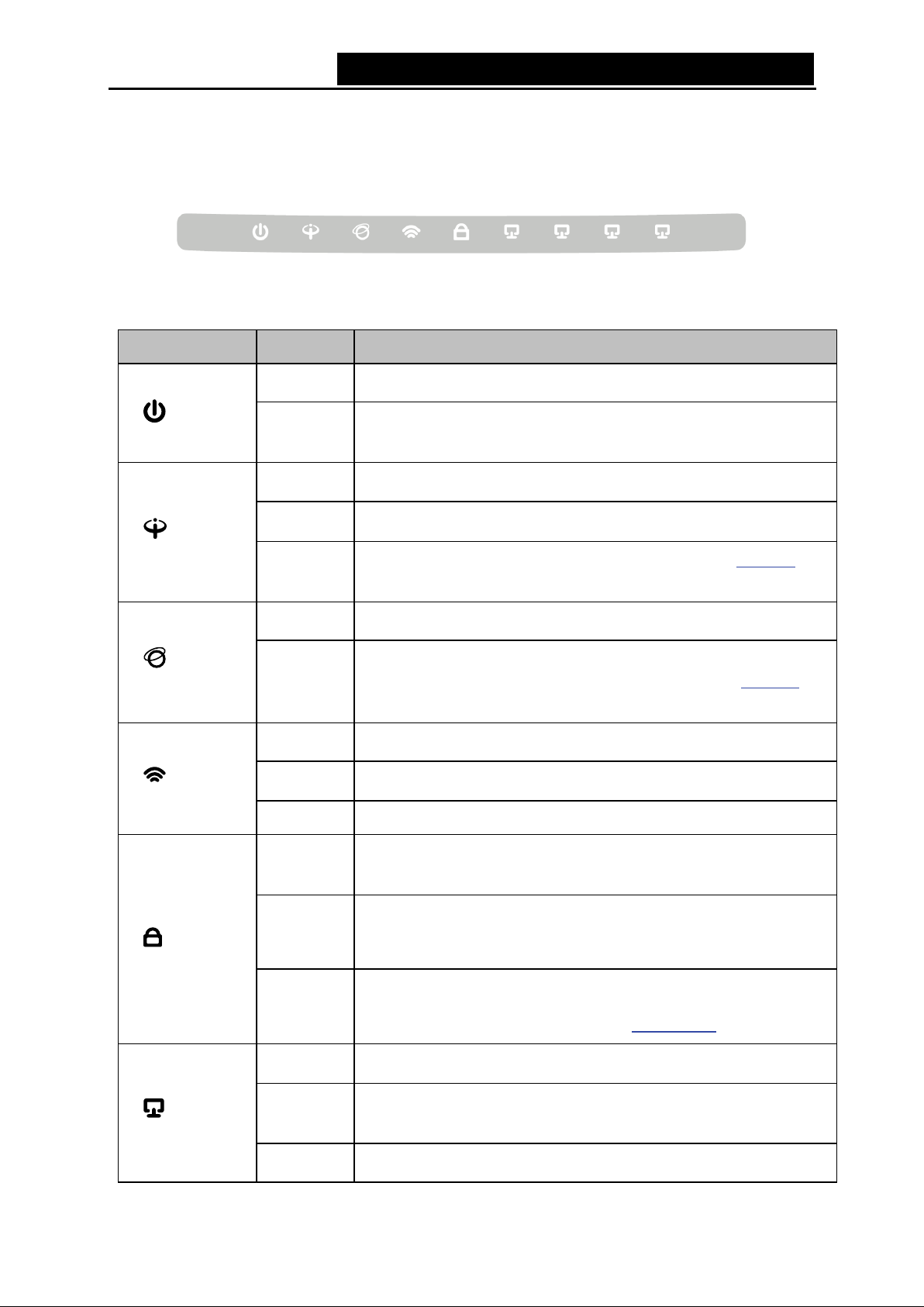
1.3.1 The Front Panel
The router’s LEDs are located on the front panel (View from left to right).
Figure 1-1
LED Explanation:
Name Status Indication
(Power)
(ADSL)
(Internet)
(Wi-Fi)
On
Off
On
Flash
Off
On
Off
On
Flash
Off Wireless is disabled.
The modem router i s pow ered on.
The modem router
connected correctl y.
ADSL line is synchronized and ready to us e.
The ADS L negotiation is in progress.
ADSL synchronization fails. Please refer to Note 1
troubleshooting.
The netw ork is avail able with a successful Internet connection.
There is no successful Internet connection or the modem router
is operating in Bridge mode. Please refer to Note 2
troubleshooting.
Wireless is enabled.
The modem router is sending or recei ving data over Wi-Fi.
for
for
On
(WPS)
(LAN1-4)
Flash
Off
On
Flash
Off
WPS function.
WPS
minutes. Please press the WPS
that you want to add to the network while the LED is flashing.
The WPS function is disabled or the wireless device
added to the network in 2 minutes after WPS function is enabled.
For more informati on, please refer to
There is a device connected to t his LA N port.
port.
There is no device connected to thi s LAN port.
4
2
WPS Set up .
Page 13
TD-W8950N 150Mbps Wireless N ADSL2+ Modem Router User Guide
Note:
1) If the ADSL LED is off, please check your Internet connection first. Refer to 2.3 Connecting
the Modem Router for more information about how to make Internet connection correctly. If
you have already made a right connection, please contact your ISP to make sure if your
I nternet servi ce is availabl e now .
2) If the Internet LED is off, please check your ADSL LED first. If your ADSL LED is also off,
please refer to Note 1. If your ADSL LED is GREEN ON, please check your Internet
configuration. You may need to check this part of information with your ISP and make sure
everything hav e been input correctl y. Refer to 4.2 Device Info for more inform ati on.
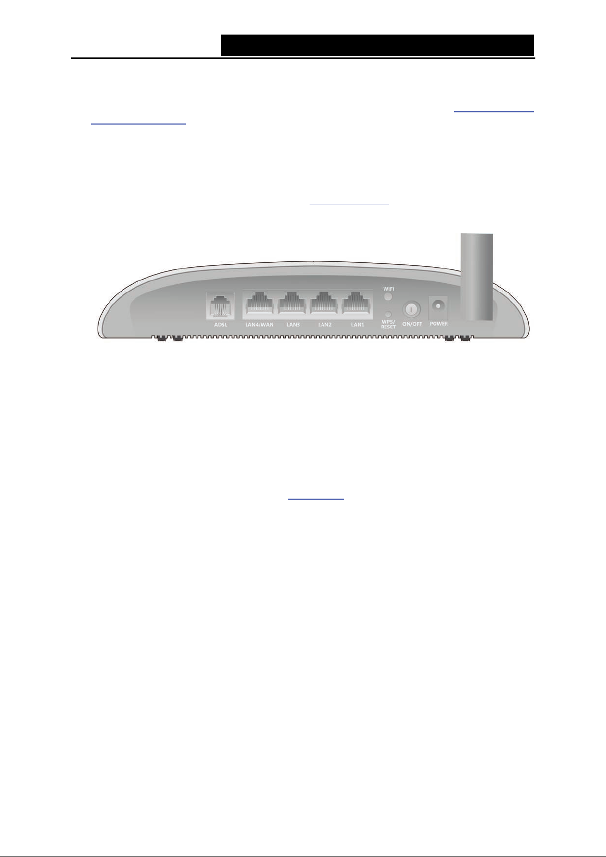
1.3.2 The Back Panel
Figure 1-2
ADSL: Connect to the M odem Port of Splitter or to the telephone l ine.
LAN4/WAN, LAN3, LAN2, LAN1: Through these ports, you can connect the router to your PC
or the other Ethernet network devices. Enable EWAN function and you will be able to connect
to Cable/FTTH /A DSL dev ice.
WiFi: The sw itch for the Wi-Fi function.
WPS/RESET:
1) WPS fu nction: For details, pl ease refer to WPS Set up
2) Reset the modem router: With the modem router powered on, press and hold down the
WPS/RESET button on the rear panel of the modem router for more than 5 seconds and then
release i t. If all LE Ds turn on mom entari ly, you restore the m odem router successfull y.
ON/OFF: The switch for the pow er.
POWER: The Power plug is w here you w i ll connect the pow er adapter.
Wireless Antennas: To recei ve and transm it the w irel ess data.
.
5
Page 14
TD-W8950N 150Mbps Wireless N ADSL2+ Modem Router User Guide
Chapter 2. Connecting the Modem Router
2.1 System R equireme nts
Broadband Internet A cces s Service (DS L/Cabl e/Et hernet).
PCs with a w orki ng Ethernet Adapter and an Ethernet cable with RJ45 connectors.
TCP /I P protocol on each PC .
Web browser, such as Microsoft Internet Explorer, Mozilla Firefox or Apple Safari.
2.2 Inst allation Environm en t Requirement s
The Product shoul d not be located w here it w il l be ex posed to mois ture or ex c essiv e heat.
Place the router in a location where it can be connected to the various devices as well as to a
power source.
Make sure the cables and power cord are safely placed out of the way so they do not create a
tripping hazard.
The router can be pl aced on a shelf or desktop.
Keep away from the strong electromagnetic radiation and the device of electromagnetic
sensitive.
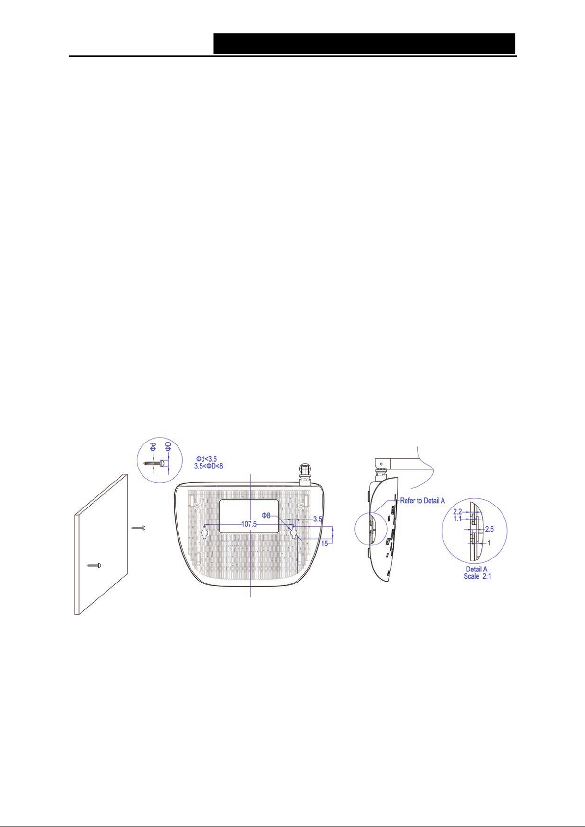
Generally, TD-W8950N is placed on a horiz ont al surface. The device also can be mounted on the
wall as shown in Figure 2-1.
Figure 2-1 Wall-mount Install
Note:
The diameter of the screw, 3.5mm<D<8mm, and the distance of two screws is 107.5mm. T he
screw that project from the wall need around 4mm based, and the length of the screw need to be
at least 20mm to withstand the weight of the product.
6
Page 15
TD-W8950N 150Mbps Wireless N ADSL2+ Modem Router User Guide
:
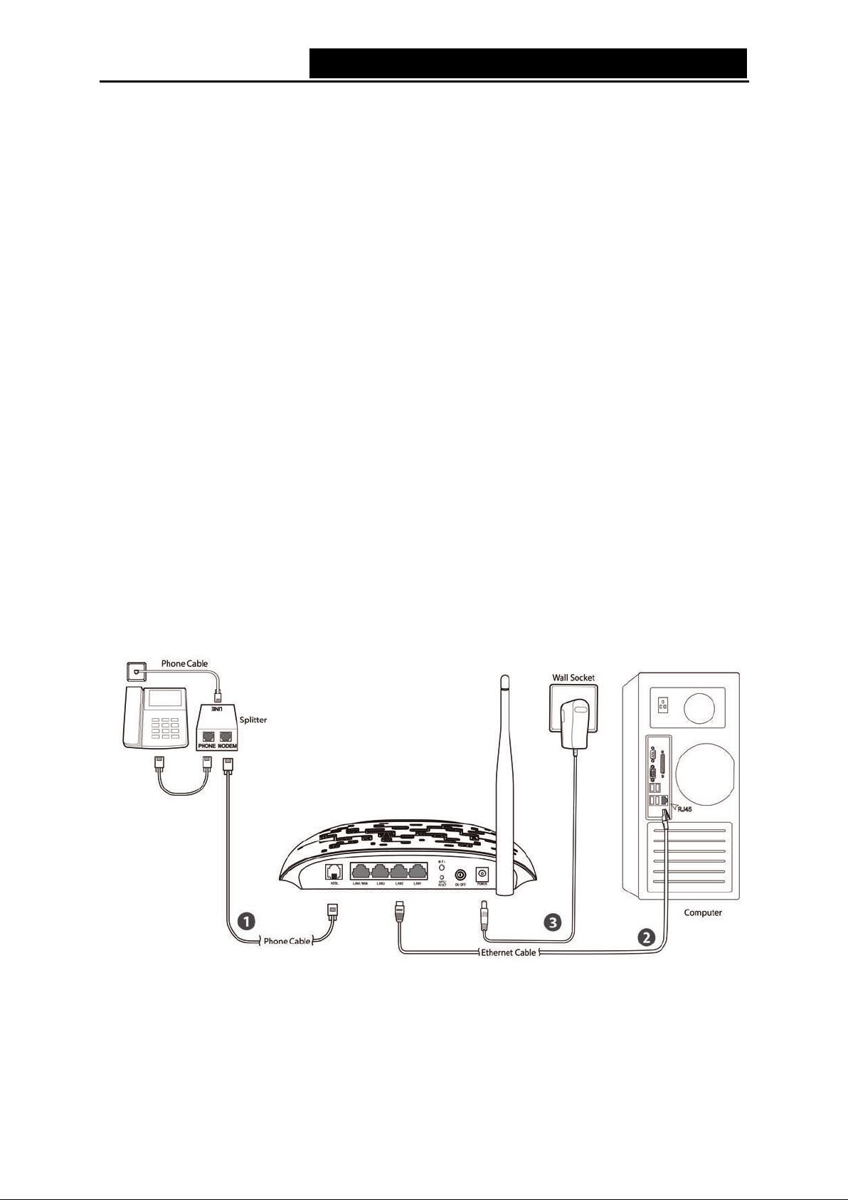
2.3 Connecting the Modem Router
Before installing the device, please make sure your broadband service provided by your ISP is
available. If there is any problem, please contact your ISP. Before cable connection, cut off the
pow er supply and keep your hands dry. You can follow the steps below to install it.
Step 1: Connect the AD SL Line.
Meth od on e: P lug one end of the tw isted-pair ADSL cable into the ADSL port on the rear
panel of TD-W8950N, and insert the other end into the wall socket.
Method two
voice, and then you can access the Internet and make calls at the same time. The
ex ternal splitter has three ports :
• LINE: Connect to the wall jack
• PHO NE: Connect to the phone sets
• MODEM: Connect to the ADSL port of TD-W8950N
Plug one end of the twisted-pair ADSL cable into the ADSL port on the rear panel of
TD-W8950N. Connect the other end to the MOD EM port of the external spli tter.
You can use a separate splitter. External splitter can divide the data and
Step 2: Connect the Ethernet cable. Attach one end of a network cable to your computer’s
Ethernet port or a regular hub/switch port, and the other end to the LAN port on the
modem router TD-W8950N.
Step 3: Pow er on the com puters and LAN devices.
Step 4: Attach the power adapter. Connect the power adapter to the power connector on the rear
of the device and plug in the adapter to an electrical outlet or power extension. The
electric al outlet shall be inst alled near the device and shall be easily accessible.
Figure 2-2
7
Page 16
TD-W8950N 150Mbps Wireless N ADSL2+ Modem Router User Guide
Chapter 3. Quick Installation Gu ide
This chapter will show you how to configure the basic functions of your TD-W8950N 150Mbps
Wireless N ADSL2+ Modem Router using Quick Setup Wizard within m inutes.
3.1 TCP/IP Configuration
The default IP address of the TD-W8950N 150Mbps Wireless N ADSL2+ Modem Router is
192.168.1.1. And the default Subnet Mask is 255.255.255.0. These values can be changed as you
desire. In this gui de, we use all the default v alues for desc ription.
Connect the local PC to the LAN/WAN port of the Router. And then you can configure the IP
address for your P C in the foll ow i ng way.
Obtain an I P address autom atical ly
1) Set up the TCP/IP Protocol in "Obtain an IP address automatically" mode on your PC.
If you need instructions as to how to do this, please refer to
PC”.
2) Then the buil t-in DHCP server w il l assign I P address for the PC .
Appendix B: "Configuring the
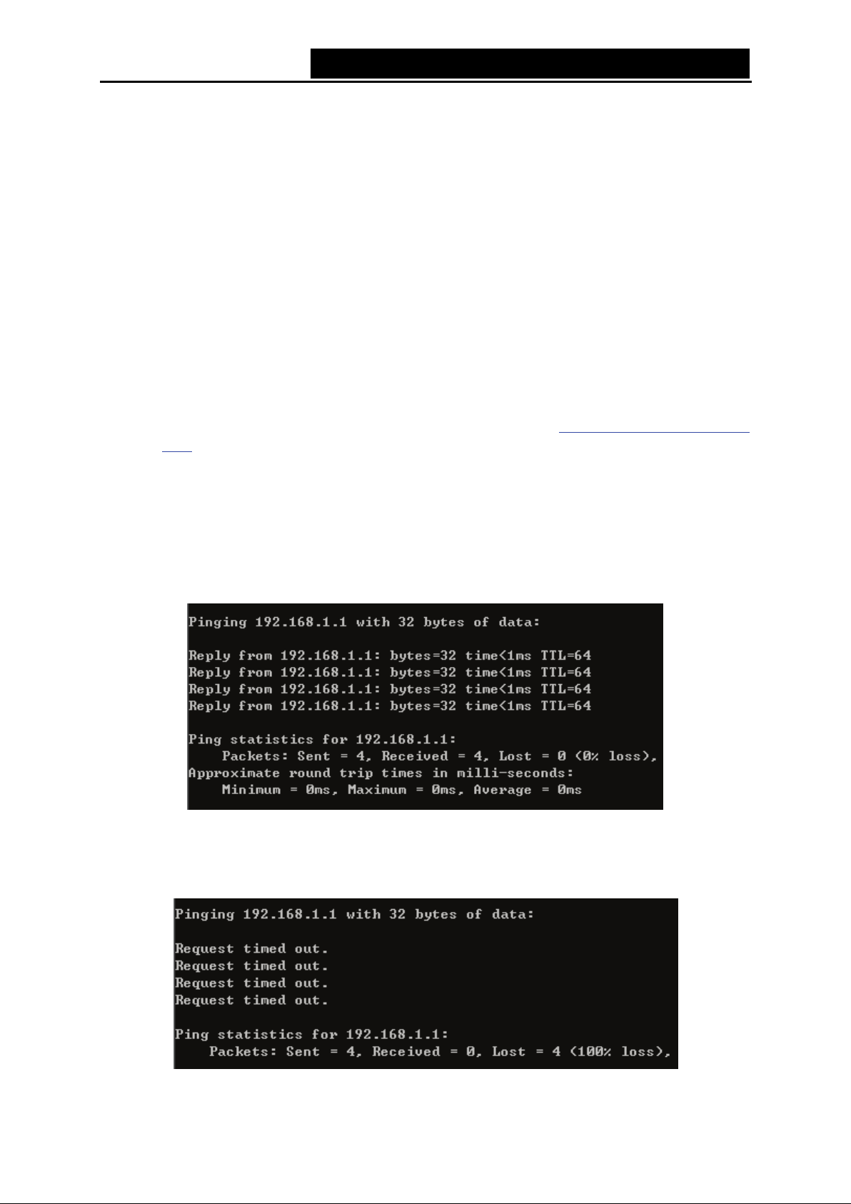
No w, you can run the Ping command in the command prompt to verify the network connection.
Please c lick the Start menu on your desktop, select run tab, type c md or co mman d in t h e f i el d
and press Enter. Type p ing 192. 168.1.1 on the nex t screen, and then press Enter.
If the result displayed is similar to the screen below, the connection between your PC and the
router has been establi shed.
Figure 3-1
If the result displayed is similar to the screen shown below, it means that your PC has not
connected to the router.
Figure 3-2
8
Page 17
TD-W8950N 150Mbps Wireless N ADSL2+ Modem Router User Guide
You can check it by following the steps below :
1) Is the connect i on betw een your PC and the router correct?
The LED of LAN port which you link to the device and the LEDs on your PC's adapter should
be lit.
2) Is the TC P /I P configura tio n for your PC correct ?
If the router's IP address is 192.168.1.1, your PC's IP address must be within the range of
192.168.1.2 - 192.168.1.254.
3.2 Quick Installation Guide
With a Web-based utility, it is easy to configure and manage the TD-W8950N 150Mbps Wireless N
ADSL2+ Modem Router. The Web-based utility can be used on any Windows, Macintosh or UNIX
OS with a Web browser, such as Microsoft Internet Explorer, Mozill a Firefox or Apple Safari.
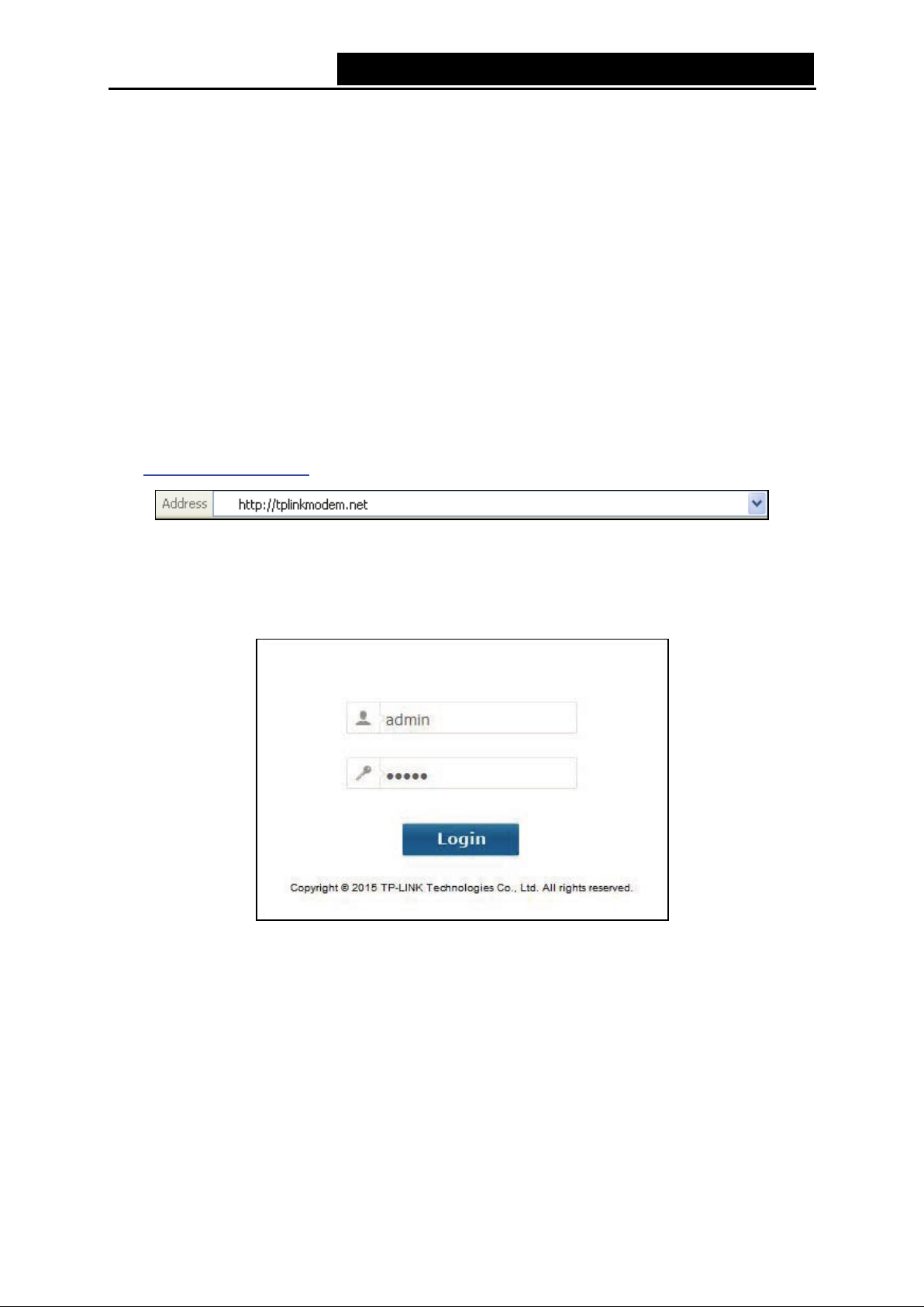
1. To access the configuration utility, open a web-browser and type the default address
http://tplinkmodem.net/
in the address fi eld of the brows er.
Figure 3-3
After a moment, a login window will appear, similar to the Figure 3-4. Enter admin for the
User Name and Password, both in lower case letters. Then click the Login button or press the
Enter key.
Figure 3-4
Note:
1) Do not mix up the user name and password with your ADSL account user name and password
which are needed for PP P connecti ons.
2) If the above screen does not pop up, it means that your Web-brow ser has been set to a proxy.
Go to Tools menu→Internet Options→Connections→LAN Se ttings, in the screen that
appears, cancel the U si ng Prox y checkbox , and clic k OK to finish it.
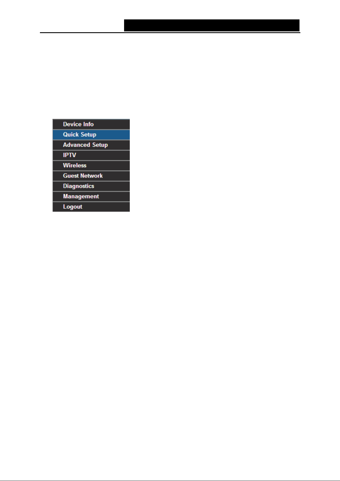
2. After your successful login, you will see the Login screen as shown in Figure 3-5. Click Quick
Setup menu to access Quick Setup Wizard and click NEXT.
9
Page 18
TD-W8950N 150Mbps Wireless N ADSL2+ Modem Router User Guide
Figure 3-5
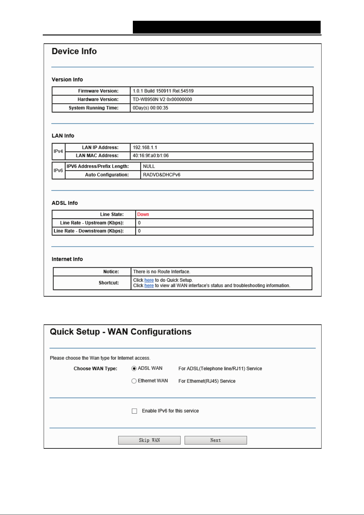
3. Choose the W AN T yp e for Internet ac cess, and then clic k Next.
Figure 3-6
10
Page 19
TD-W8950N 150Mbps Wireless N ADSL2+ Modem Router User Guide
Note:
1) The Quick Setup Wizard will guide you to configure the WA N Servi ce over ATM interface.
2) If you are unwilling to configure WAN Service now, you can click the Sk ip W AN button. Then
you can configure WA N service referring to 4.4.1 Layer2 I nterface
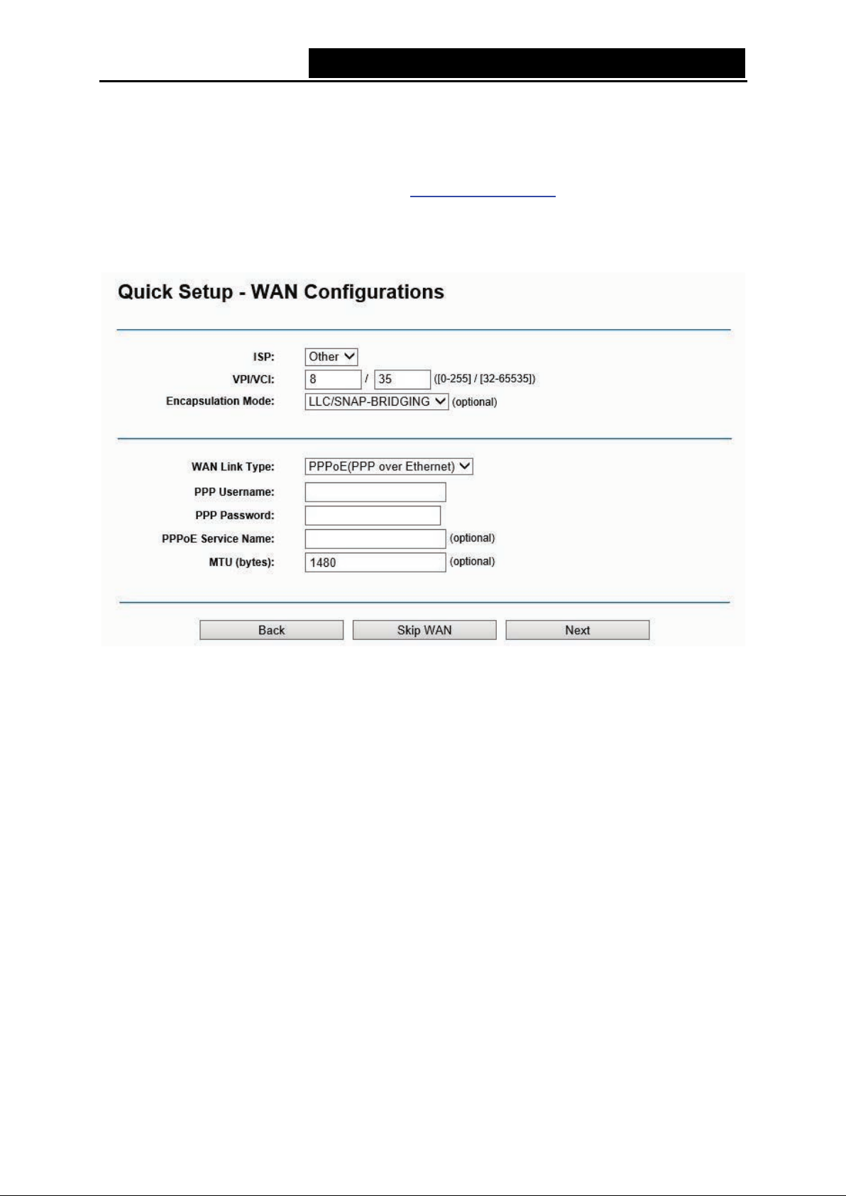
4. If AD SL WAN is chosen, please select your ISP from the drop-down list. Select WAN Li nk
Type provided by your ISP and enter the related parameters, and then click Next. Here we
use PP P oE as an exam pl e.
.
Figure 3-7
Note:
If your ISP is not listed, please select Other. Then you can manually enter the VPI/VCI values and
select WAN Link Type provided by your IS P.
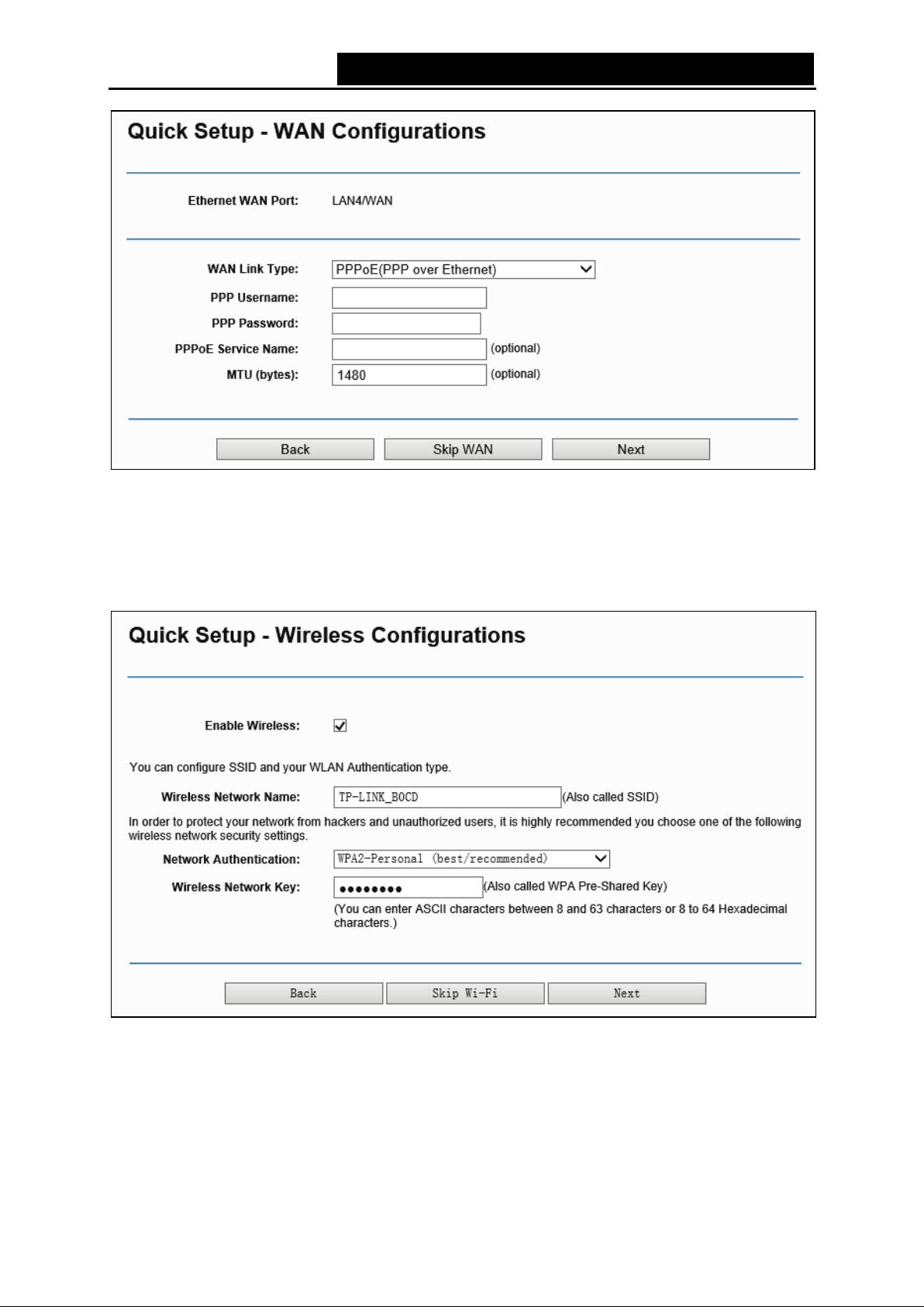
If Ethe rnet WAN is chosen, please select WAN Link Type provided by your ISP and enter the
related param eters, then cl ick Next. H ere w e use PP PoE as an ex am ple.
11
Page 20
TD-W8950N 150Mbps Wireless N ADSL2+ Modem Router User Guide
Figure 3-8
5. The WLAN function is enabled by default. You can rename your wireless network name and
create your own password in this page. The default wireless name is TP-LINK_XXXXX X, and
the default wireless password, the same as the PIN code, is printed on the bottom label. Click
Next to continue.
Figure 3-9
6. You will see the Summary screen below , click Confirm to m ake your settings t ake effect.
12
Page 21
TD-W8950N 150Mbps Wireless N ADSL2+ Modem Router User Guide
Chapter 4. Configuring the Modem Router
This chapter will show each Web page's key func tion and the confi guration w ay .
4.1 Login
After your successful login, you will see th e main menus on the left of the Web-based utility. On
the right, there are the corresponding ex planati ons and inst ructions.
The detailed ex pl anations for each Web page’s key function are list ed below .
4.2 Device Info
Choose “Device Info” menu, there are six submenus under the main menu: Summary, WAN,
Statistics, Route, ARP and DHCP. This Device Info section mainly introduces the elementary
information about the router and its current settings in use. Click any of them, and you will be able
to view the corresponding information.
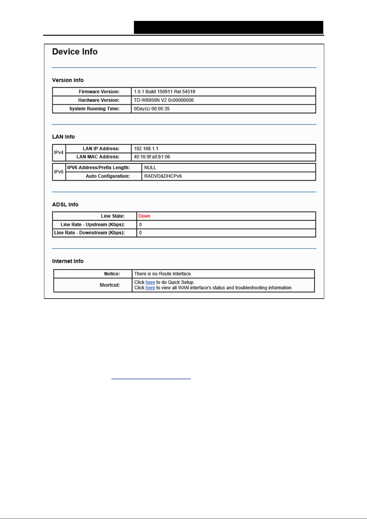
Choose “Device Info”“Summary”, you will see the Summary screen (shown in Figure 4-1). The
first table indicates the information about the version including Software and Hardware. The
second table displays the current status of the TD-W8950N connection. This information will vary
depending on the setti ngs of the router confi gured on the Advanc ed Setup screen.
13
Page 22
TD-W8950N 150Mbps Wireless N ADSL2+ Modem Router User Guide
Figure 4-1
Note:
Click the other submenus under the main menu Dev ice Info, and you will be able to view the
corresponding inf ormati on about WAN, Statistics, Route, ARP and DHCP.
4.3 Quick Set up
Pleas e refer to Section 3.2 Quick Installation Guide.
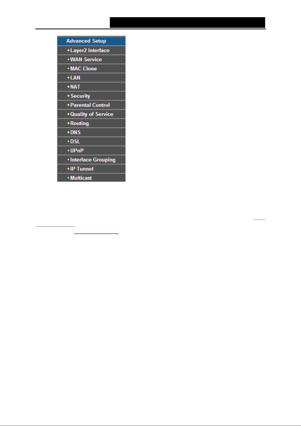
4.4 Advanced Setup
Choose “Advanced Setup”, there are many submenus under the main menu. Among the
submenus, Layer2 Interface, WAN Service, LAN etc. are default menus, while NAT will appear
only when you select some corresponding functions. Click any one of them, and you will be able to
configure the correspondi ng functi on.
14
Page 23
TD-W8950N 150Mbps Wireless N ADSL2+ Modem Router User Guide
This Advanced Setup section mainly introduces how to configure the router fo r adequate use. The
detailed explanations for each subsection are provided bel ow .
Note:
To completely configure the WAN Interface, you need to first select the Layer2 Interface (4.4.1
Layer2 Interface) according to the connection ISP provides for you, and then to select the type of
the connection (4.4.2 WAN Service) for the further configuration.
4.4.1 Layer2 I nt er f ace
Choose “Advanced Setup”“Layer2 Interface”, and you can select WAN Service Interface
(layer2 interface) over ATM Interface or ETH Interface.
ATM Interface: Configure the router to access Internet as an ADSL u ser. ISP provides you
VPI (Virtual Path Identifier), VCI (Virtual Channel Identifier) settings and the DSL Interface
with RJ11 connector. (Figure 4-2)
ETH Interface: Configure the router to access Internet as an Ethernet user. ISP provides you
Broadband I nternet Servi ce and the Ethernet I nterface with RJ45 connector.
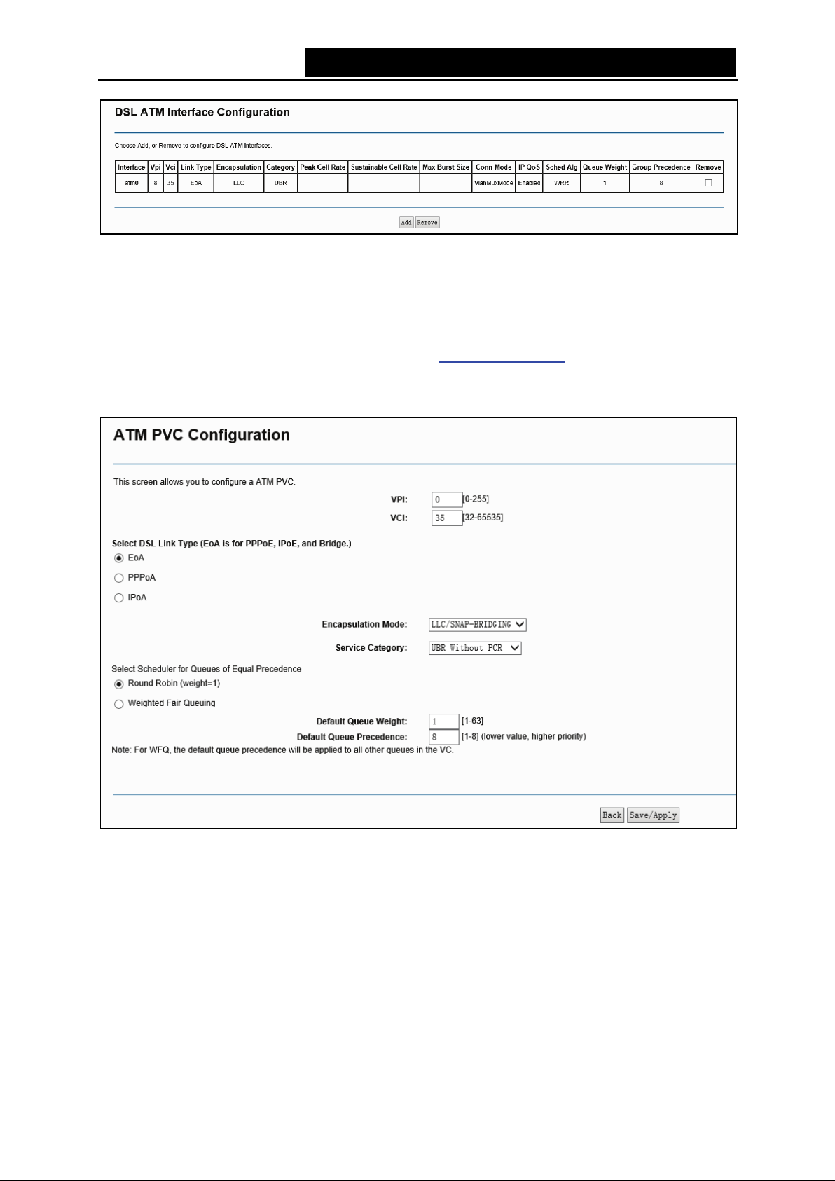
4.4.1.1 ATM Interface
Choose “Advanced Setup”“Layer2 InterfaceATM Interface”, you can Configure ATM
interfaces on the screen bel ow .
15
Page 24
TD-W8950N 150Mbps Wireless N ADSL2+ Modem Router User Guide
Figure 4-2
Remove: Select the check box in the table on the screen above and then click the Remove
button, the corresponding i nterface will be deleted in the table.
Note:
If the interface is used by the configuration of the 4.4.2 WAN Service, you nee d to r emo ve t he
corresponding WAN Serv ice entry first before you can remove it here.
Add: Click the button, and y ou can add a new interface i n the next screen.
Figure 4-3
VPI/VCI: the VPI and VCI values provided by your ISP. Do not change them unless it was
required by your I SP.
DSL Link Type: Select a D SL Link Type which is provided by your ISP. T he options include
EoA (it is for PPPoE, IPoE, and Bridge), PPPoA (PPP ov er ATM) and IPoA (IP over ATM ).
Encapsulation Mode: The mode of the data processing over the Link Type you have
selected. Uses the default setting, i f you are not sure.
Service Category: Select the type of the service assigned by your ISP in the drop-down list.
The default type i s UBR Without PCR.
16
Page 25
TD-W8950N 150Mbps Wireless N ADSL2+ Modem Router User Guide
Note:
The detailed configuration about Scheduler for Queues of Equal Precedence will be described
in Quality of Service
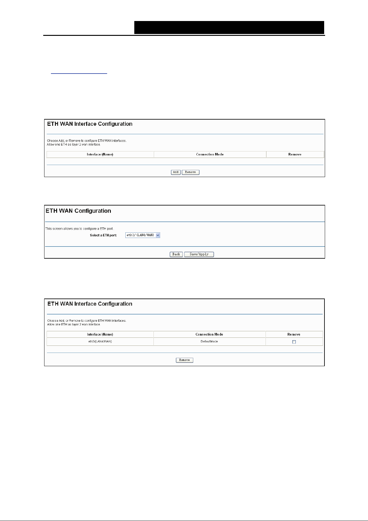
4.4.1.2 ETH Interface
Choose “Advanced Setup”“Layer2 Interf aceETH Interface”, you can configure ETH WAN
interfaces on the screen bel ow .
.
Figure 4-4
Add: Click the Add button, and you c an add a new interface in the nex t screen.
Figure 4-5
ETH port: Select an E TH port to confi gure as the WAN port.
Click Save/Apply to save your settings and then y ou w i ll see the screen sim il ar to Figure 4-6.
Figure 4-6
Remove: Select the check box in the table on the screen above and then click the Remove
button, the corresponding interface will be deleted in the table.
Note:
Only one E TH is allowed to configure as the layer 2 WAN Interface.
4.4.2 WAN Service
Choose “Advanced Set up”“WAN Service”, and you will see the WAN Port Information Table in
the screen similar to Figure 4-7, which describes the WAN port settings and the relevant
manipulation to each interface. After you add a new Lay2 Interface, please follow the instructions
17
Page 26
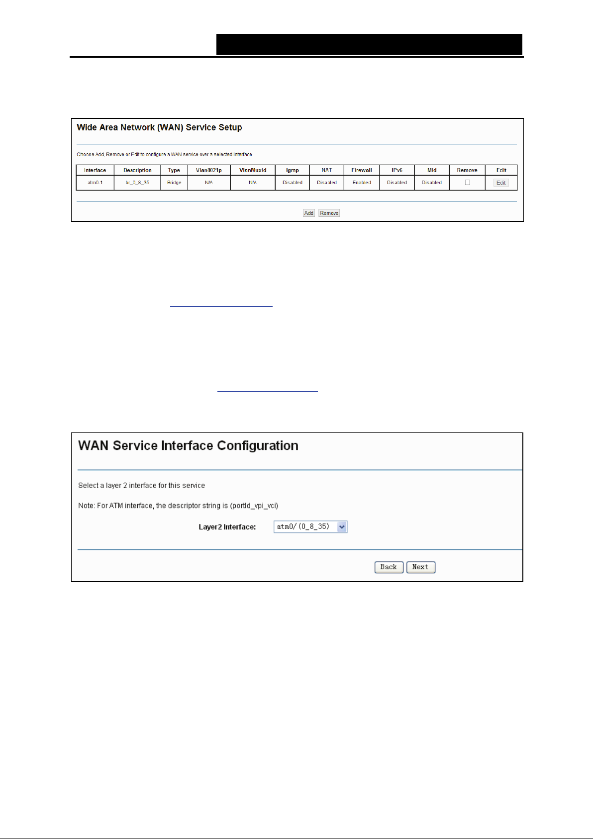
TD-W8950N 150Mbps Wireless N ADSL2+ Modem Router User Guide
below to complete the further configuration of WAN Interface. There are five different
configurations for the connection types, which are PPPoE, IPoE, Bridge, PPPoA, and IPoA. You
can selec t the corresponding types according t o your needs.
Figure 4-7
Note:
The following section adopts different VPI, VCI to introduce further configuration for the differ ent
connection types, if you need to change the configuration of ATM PVC ( VPI/VCI), you should go to
the previous section (4.4.1 Layer2 I nterface
4.4.2.1 ATM-EoA-PPPoE
) to confi gure them again.
If your ISP provides a PPPoE connection and you need to use an ATM Interface, follow the steps
below to add a WAN service ov er a selec ted ATM interface:
1. Add a new ATM interface (4.4.1.1 ATM Interface
2. Click the Add button on the screen Figure 4-7 and you will enter the next screen as shown in
Figure 4-8. Click Next.
Figure 4-8
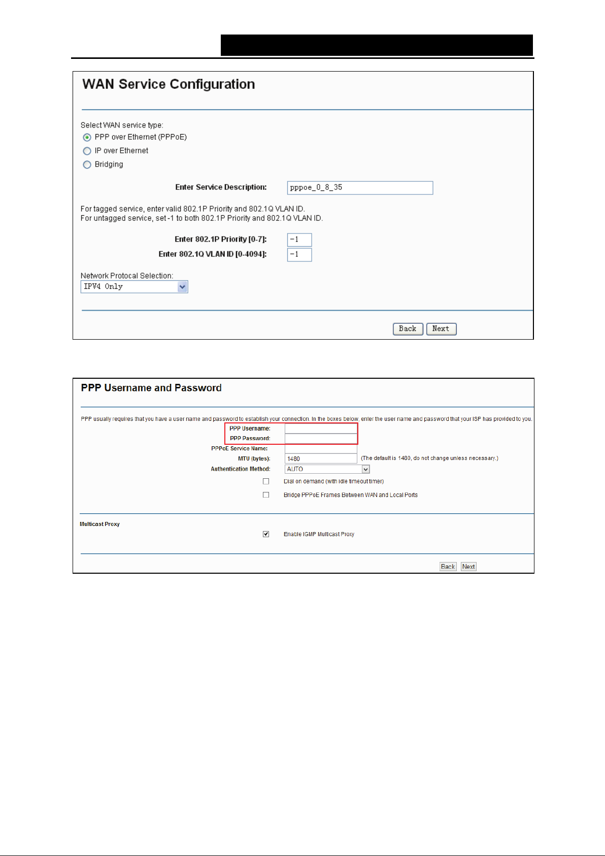
3. Select the WAN ser vi ce typ e in Figure 4-9. If your ISP provides a PPPoE connection, select
PPPoE option. You can create a service name for the Service Description or leave it the
default nam e. Click Next.
).
18
Page 27
TD-W8950N 150Mbps Wireless N ADSL2+ Modem Router User Guide
Figure 4-9
4. Enter the following parameters and then click Next.
Figure 4-10
PPP Username/Password: Enter the Username and Password provided by your ISP. These
fields are case-sensitive.
PPPoE Service Name: Enter the Service Name if it was provided by your ISP. You can leave
it blank, if the I SP doesn’t provide it.
M TU (bytes): Maximum Transmission Unit Size. Check this box then you can change the
MTU s ize. The default MTU value is 1480 Bytes. It is not recommended that you change the
default value unless required by your I SP .
Authentication Method: Select the Authentication Method from the drop-down list, the
default m ethod is AUTO, and you can leave it as a default setting.
Dial on demand (with idle timeout timer): The router will cut off the Internet connection after
it has been inactive for a specific period of time (idle timeout), and it will automatically
19
Page 28
TD-W8950N 150Mbps Wireless N ADSL2+ Modem Router User Guide
re-establish the connection as soon as you attempt to access the Internet again. If your
Internet is charged by time you may want to selec t this option in order to save money.
Brid ge PPPoE Frame s Between WAN and Local Ports: Select this option to enable PPP
connection i n your local PC .
Enable IGMP Multicast Proxy: IGMP (Internet Group Management Protocol) is used to
manage multicasting on TCP/IP networks. Some ISPs use IGMP to perform remote
configuration for client devices, such as the router. The default value is enabled, and if you
are not sure, pleas e contact y our I SP or just leave it.
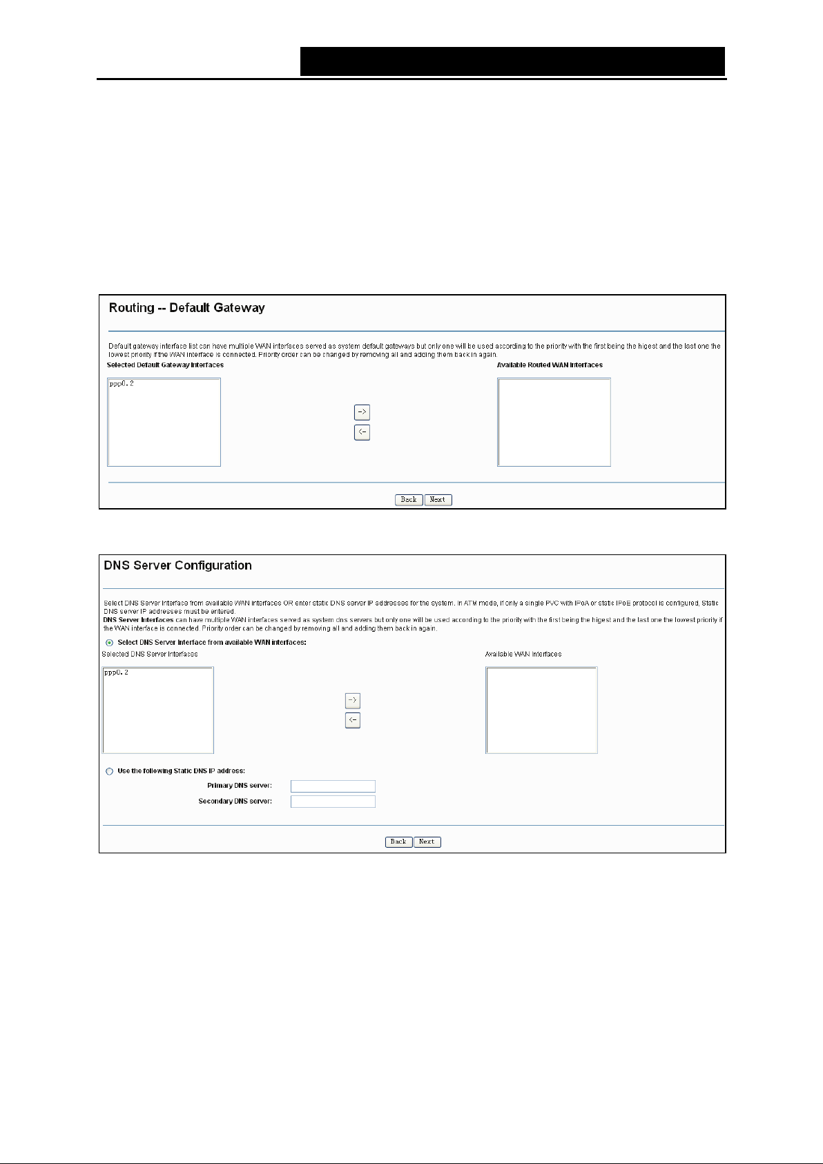
5. Select a preferred wan interface as the system default gateway in Figure 4-11 and click Next.
Figure 4-11
6. Configure the DNS Server Addresses on the screen below and click Next.
Figure 4-12
Select DNS Server Interface f rom available WAN Interfaces: You can select this option to
automatically get DN S server informati on from the selected WA N interface.
Use the following Static DNS IP Address: You can select this option to manually enter the
prim ary and /or optional secondary DNS server IP addresses provided by y our I SP .
Note:
If only single PV C wi th IP oA is configured, you m us t enter stati c DN S server I P addresses.
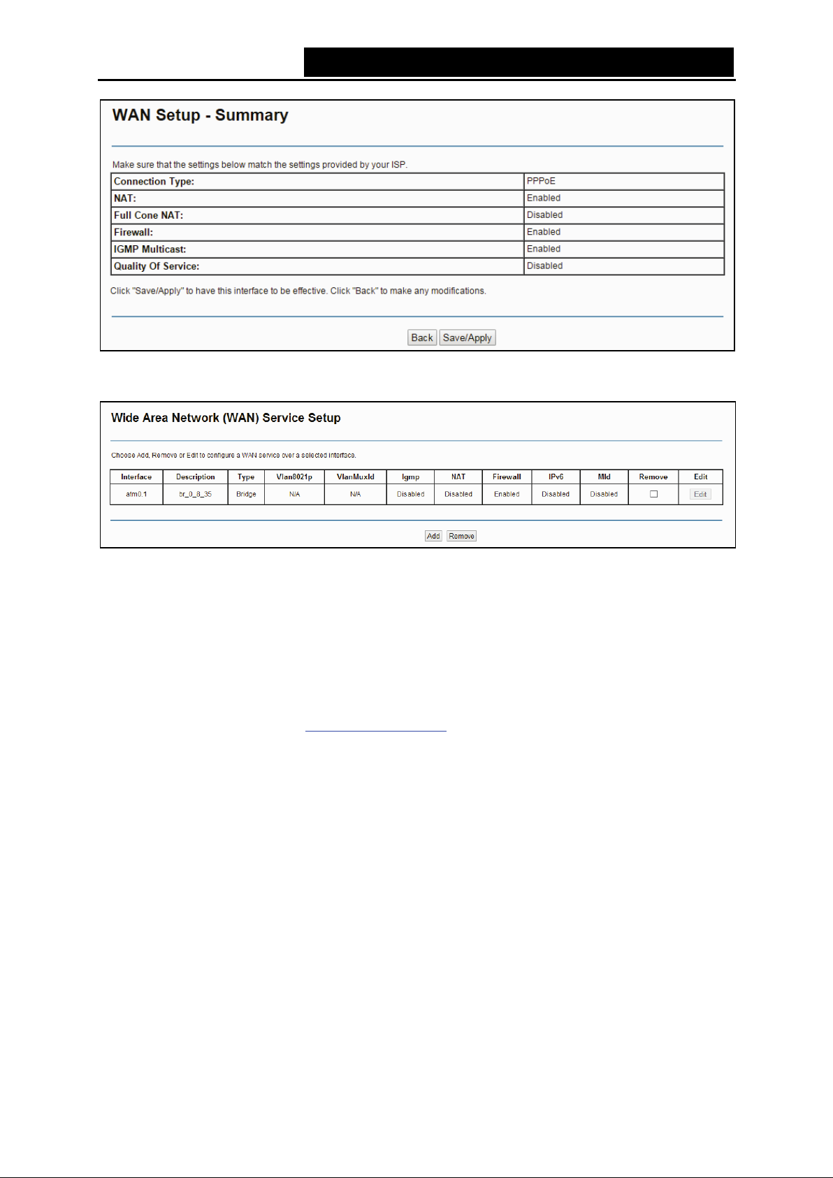
7. On the next screen you will see the detailed settings you’ve made. Please click the
Save/Apply button to save these setti ngs.
20
Page 29
TD-W8950N 150Mbps Wireless N ADSL2+ Modem Router User Guide
Figure 4-13
8. On the next screen you will see the WAN Port Information Table with the new configuration.
Figure 4-14
Remove: Select the check box in the table above and then click Remove , the corresponding
interface will be deleted.
4.4.2.2 ATM-EoA-IPoE
If yo u r ISP provides an IPoE connection and you need to use an ATM Interface, follow the steps
below to add a WA N servic e over a selected ATM interface:
1. Add a new ATM interface (4.4.1.1 ATM Interface
2. Click the Add button on the screen (as shown Figure 4-7). Select WAN Service Interface over
ATM PVC on the next screen (as shown Figure 4-8).
3. If your ISP provides an IPoE connection, select IP over Ethernet option for the WAN service
type on the screen (as shown Figure 4-9), and click Next button to c ontinue.
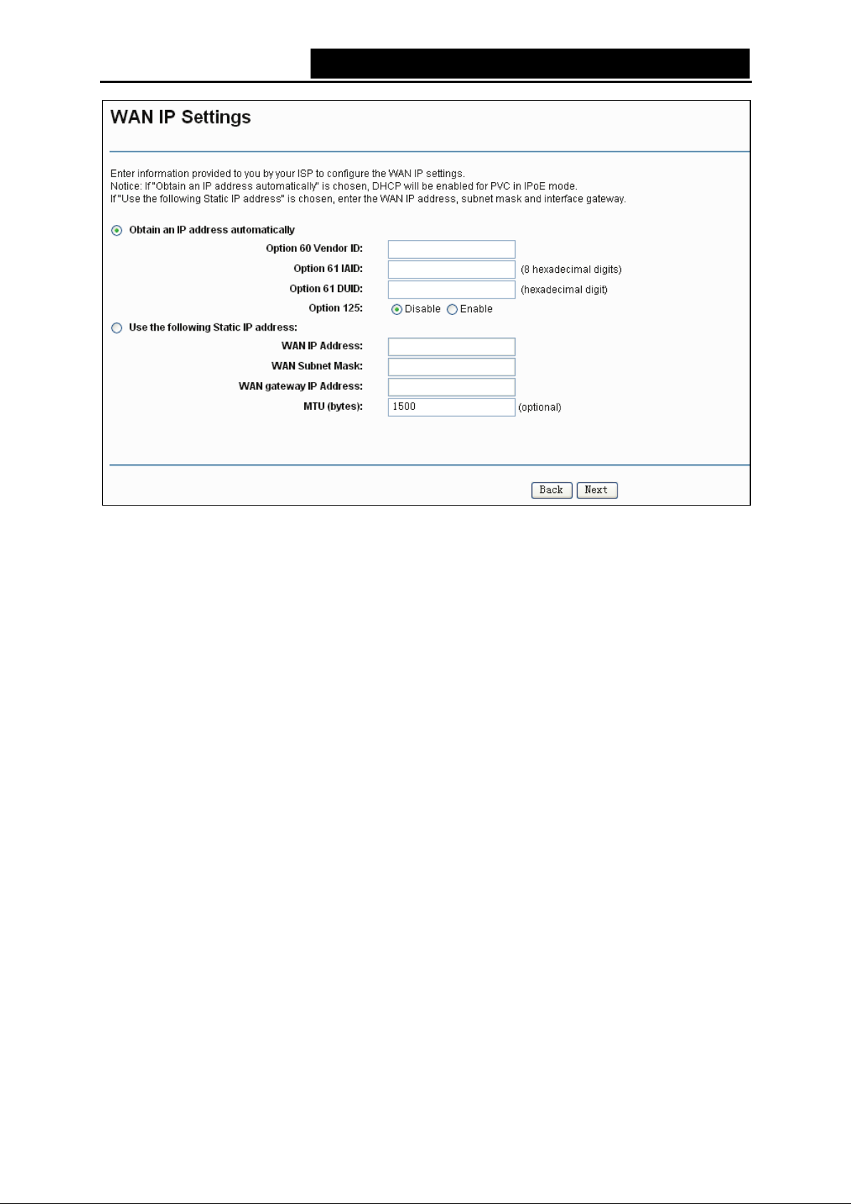
4. Enter paramet ers in the foll ow ing blanks to configure the WAN IP Add r ess and click Next.
).
21
Page 30
TD-W8950N 150Mbps Wireless N ADSL2+ Modem Router User Guide
Figure 4-15
Obtain an IP address au tomatically: Select this option, the router will be able to obtain IP
netw ork informati on dynam ic ally from a DHCP server provided by your ISP .
Note:
1) The response message from a DHCP server typically contains a number of configuration
parameters (DHCP options) for the router. The DHCP options include IP network information,
and a lso th e vendor-specific options. In some cases, the router is implemented to perform
user-defi ned oper ations (as shown below). You can implement your own treatment of all such
options.
2) If the router is functioning as a DHCP client, it must identify itself in option 61 (client-identifier)
in every DH CP mes sage. DUID/IAID is portion of option 61.
• Option 6 0 V endor ID: The option code 60 used to identify Vendor class.
• Option 61 IAID: IAID (Identity Association ID) assigns an Identity Association ID to
individual interfaces. In cases where the device is functioning with a single DHCP client
identity, it must use value 1 for IAID for all DHCP interactions. In cases where the device
is functioning with multiple DHCP client identities, the values of IAID have to start at 1 for
the first identity and be incremented for each subsequent identity. For example, the
device may use IAID value 1 for the first physical interface and value 2 for the second.
Alternatively, the device may use IAID value 1 for the virtual circuit corresponding to the
first connection object in the data model and value 2 for the second connection object in
the data model.
• Option 61 DUID: Specifies the name of the interface whose link-layer address the server
is to use as its DUID ( DHCP Unique Identifier). You must enter a value for this parameter
or the server will not start. When the server starts, the DUID is w ritten to the system log.
22
Page 31

TD-W8950N 150Mbps Wireless N ADSL2+ Modem Router User Guide
• Option 125: The option 125 allows DHCP server to be pre-configured with policy for
handling classes of devices in a certain way without requiring DHCP server to be able to
parse the unique form at used in cl ient-identifi er option.
Use the following IP Address: If you are provided with a static IP/gateway Address, please
select this option, and then enter the WAN IP Addre ss, WAN Subnet Mask and WAN
gateway I P Address manually.
5. You will see the next screen as below. You can enable the NAT, SPI Firewall, and IGM P
Multicast, if you are not sure about the setti ngs, just leave the defaul t setti ngs. Click Next.
Figure 4-16
Enable NAT: This technology translat es the IP addresses of a local area network to t he WAN
IP address for the Internet. If this router is hosting your network’s connection to the Internet,
please select the check box. If another router exists in your networ k, you don’t need to select
the option.
Enable Firewall: A SPI firewall enhances network’s security. Select the option to use a
firew al l, or else w i thout a firew all .
E nable IGMP Multicast: This is enabled by default. This setting will not allow IGMP (Internet
Group Management Protocol) packets to be forwarded to the LAN. IGMP is used to manage
multicasting on TCP/IP networks. Most users will not need to enable this. Some ISPs use
IGMP to perform remote configur ation for client devices, such as the router. If you are unsure,
check with your I S P .
Note:
If you select the Enable NAT checkbox, the NAT menu will be added to the Web-based Utility. We
will de scrib e the detailed configuration i n 4.4.5 NAT
.
23
Page 32

TD-W8950N 150Mbps Wireless N ADSL2+ Modem Router User Guide
6. Select a preferred WAN interface as the syst em default gatew ay and click Next.
Figure 4-17
7. Configure the DNS Server Addresses on the screen as follows.
Figure 4-18
Note:
If only single PV C wi th IP oA is configured, you m us t enter static DNS server IP addresses.
8. On the next screen (as shown Figure 4-19) you will see the detailed settings you’ve made.
Please click the Save/Apply button t o save these settings.
24
Page 33

TD-W8950N 150Mbps Wireless N ADSL2+ Modem Router User Guide
Figure 4-19
4.4.2.3 ATM-EoA-Bridging
If you want to adopt the Bridge service and you need to use an ATM Interface, follow the steps
below to add a WA N servic e over a selected ATM interface:
1. Add a new ATM interface (see 4.4.1.1 ATM Interface
2. Click the Add button on the screen Figure 4-7. Select WAN Service Interface over ATM PVC
on the next screen (as show n Figure 4-8).
3. Select Bridging option for the WAN service type on the screen (as shown Figure 4-9), and
click Next button to conti nue.
4. On the screen (as shown Figure 4-13) you will see the detailed settings you’ve made. Please
click the Save/Apply button to save these sett ings.
4.4.2.4 ATM-PPPoA
If your ISP provides a PPPoA connection and you need to use an ATM Interface, follow the steps
below to add a WA N servic e over a selected ATM interface:
1. Add a new ATM interface and select PPPoA option for DSL Link Type (see 4.4.1.1
Interface).
2. Click the Add button on the screen Figure 4-7 and the next configuration is similar to PPPoE,
(see section 4.4.2.1 ATM-EoA-PPPoE
PPPoE Service Name and Bridge PPPoE Frames Between WAN and Local Ports on the
screen of
4.4.2.5 ATM-IPoA
Figure 4-10.
). The difference is that you don’t need to set the
).
ATM
If yo u r ISP provides an IPoA connection and you need to use an ATM Interface, follow the steps
below to add a WA N servic e over a selected ATM interface.
1. Add a new ATM interface and select IPoA option for DSL Link Type (see 4.4.1.1
Interface).
2. Click th e Add button on the screen Figure 4-7 and the next configuration is similar to IPoE
(see section 4.4.2.2 ATM-EoA-IPoE
). The difference is that you have to manually set the
25
ATM
Page 34

TD-W8950N 150Mbps Wireless N ADSL2+ Modem Router User Guide
Static IP Address on the screen of Figure 4-15, and the Static IP Address for DNS Server on
the screen of Figure 4-18.
4.4.2.6 ETH-PPPoE
If your ISP provides a PPPoE connection and you need to use an ETH Interface, follow the steps
below to add a WA N servic e over a selected ETH interface:
1. Add a new ETH interface on t he screen of 4.4.1.2 ETH Interface
2. Click the Add button on the screen Figure 4-7 and the following configuration is similar to
PPPoE over ATM interface (see sec tion 4.4.2.1 ATM-EoA-PPPoE
4.4.2.7 ETH-IPoE
If yo u r ISP provides an IPoE connection and you want to use an ETH Interface, follow the steps
below to add a WA N servic e over a selected ETH interface:
1. Add a new ETH interface on t he screen of 4.4.1.2 ETH Interface
2. Click th e Add button on the screen Figure 4-7 and the next configuration is similar to IPoE
over ATM interface (see section 4.4.2.2 ATM-EoA-IPoE
4.4.2.8 ETH-Bridge
If you want to adopt the Bridge service and you need to use an ETH Interface, follow the steps
below to add a WA N servic e over a selected ETH interface:
1. Add a new ETH interface on t he screen of 4.4.1.2 ETH Interface
2. Click the Add button on the screen Figure 4-7 and the next configuration is similar to Bridge
over ATM interface (see section 4.4.2.3 ATM-EoA-Bridg
).
).
.
).
.
.
4.4.3 MAC Clone
Choose menu “Advanced Setup”“MAC Clone”, you can configure the MAC address of the
WAN Interfac e as shown below.
The WAN Interface List displays the Lay2 Interfaces you have configured on the section 4.4.1
Layer2 Interface and its default MAC Address. If you have not configured corresponding WAN
Service for the interface on the section 4.4.2 WAN Service, the blank for MAC Address will display
“Need a corresponding WAN Service”.
The last one of W AN Interface Li st displays your P C’s current address.
Figure 4-20
Type the new value for the WAN Interface whose M AC Address you want to change.
You can select corresponding WAN Interface from the drop-down list and click Clone button to
clone your current PC M A C.
26
Page 35

TD-W8950N 150Mbps Wireless N ADSL2+ Modem Router User Guide
Click Restore Defau lt but ton to restore the WA N Interface’s default M AC Address.
Note:
Only the WAN Ports can use MAC Address Clone function. All the clone MAC addresses must not
be the sam e w ith each other.
4.4.4 LAN
4.4.4.1 IPv4 LAN Con fig
Choose “Advanced Setup”“LAN”, and you will see the LAN screen (shown in Figure 4-21), the
section al lows you to configure the router’ s LAN ports setti ngs.
Figure 4-21
IP Address: Y ou can conf igure the router’s I P Address and S ubnet M ask for LAN I nterface.
• IP Add ress: Enter the router’s local IP Address, then you can access to the Web-based
U til ity via the I P Address, the default value i s 192.168.1.1.
• S ubnet Mask : E nter the router’s Subnet M ask , the default value is 255.255.255.0.
Enable IGMP Snooping: If you select the option, please choose the IGMP Mode: Standard
Mode or Block ing Mode.
E nable LA N side firewall: You can click the check box to enable LAN side firewall.
DHCP Server : These settings allow you to configure the router‘s Dynamic Host Configuration
Protocol (DHCP) server function. The DHCP server is enabled by default for the router’s
Ethernet LAN interface. DHCP service will supply IP settings to computers which are
configured to automatically obtain IP settings that are connected to the router though the
Ethernet port. If you enable the DHCP server, the router becomes the default gateway for
27
Page 36

TD-W8950N 150Mbps Wireless N ADSL2+ Modem Router User Guide
DHCP client connected to it. Keep in mind that if you change the IP address of the router, you
mus t change the range of I P addresses in t he pool us ed for DH C P on the LAN .
• Start IP Address: Enter a value for the DHCP server to start with when issuing IP
addresses. Because the default IP address for the router is 192.168.1.1, the default Start
IP Address is 192.168.1.100, and the Start IP Address must be 192.168.1.2 or greater, but
sm aller than 192.168.1.254.
• End IP Address: Enter a value for the DHCP server to end with when issuing IP
addresses. The End IP Address must be smaller than 192.168.1.254. T he default End IP
Address is 192.168.1.200.
• Lea sed Time (hour): T he Leased Time is the amount of time in which a network user will
be allowed to connect to the router with their current dynamic IP address. Enter the
amount of time, in hours, then the user will be “leased” this dynamic IP address. The
default is 24 hours.
Static IP Lease List: The function allows you to specify a reserved IP address for a PC on the
LAN, that PC will always obtain the assigned IP address each time when it accesses the
DHCP server. Reserved IP addresses should be assigned to servers that require permanent
IP settings. Click the Add Entries button in Figure 4-21, and then you will set the ru l e i n th e
screen as below .
Figure 4-22
• MAC Address: The MAC address of the computer on the LAN which you want to reserve
an I P.
• IP Address: The IP address you want to reserved for the computer.
4.4.4.2 IPv6 LA N Config
Choose “Advanced Setup”“LAN” “IPv6 LAN Config”, and you will see the LAN screen
(shown in Figure 4-23), here you can c onfigure LA N IP v6 interface for your m odem router.
28
Page 37

TD-W8950N 150Mbps Wireless N ADSL2+ Modem Router User Guide
Figure 4-23
Interface Address (prefix length is required): Here enter your interface address with its
prefix length.
IPv6 LAN Applications: Select a type to assign IPv6 addresses to the computers in your
LAN. DHCPv6 Server and RAD VD are provided.
For DHCPv6 Server:
1) If Stateless is select ed, it doesn’t need to be configured.
2) If Stateful i s selec ted, please com plete t he following param eters.
• Start interface ID: Enter a value for the DHCPv6 server to star t with when issuing IPv6
addresses.
• End in te r fa ce I D : Enter a value for the DHCPv6 server to end with when issuing IPv6
addresses.
• Leased Time (hour): The Leased Time is the amount of time in which a networ k user will
be allowed to connect to the modem router with their current dynamic IPv6 address.
Enter the amount of time, in hours, then the user will be “leased” this dynamic IPv6
29
Page 38

TD-W8950N 150Mbps Wireless N ADSL2+ Modem Router User Guide
address. After the dynamic IPv6 address has expired, the user will be automatically
assigned a new dynamic IPv6 address. The default is 24 hours.
For RADVD:
1) If Random ly Generate is selec ted, it doesn’t need to be configured.
2) If Statically Configure i s selec ted, please com plete t he following param eters.
• Prefix: Enter a value for the site prefi x .
Click Save/Apply to make the configuration take eff ect.
4.4.5 NAT
NAT (Network Address Translation) allows you to share one WAN (Wide Area Network) IP
address for m ulti ple computers on your LAN (Local A rea Network).
Note:
When you select PPPoA or PPPoE for the WAN Setup, or when you select Enable NAT for the
type of IPoA and IPoE connection (4.4.2 WAN Service
Web-based U t ili ty (show n in Figure 4-24).
), you will see the NAT menu in the
Figure 4-24
Choose “Advanced Setup”“NAT”, there are 4 submenus under the main menu: Virtual
Servers, Port Triggering, DM Z Host and ALG. Click any of them, and you will be able to
configure the correspondi ng functi on.
30
Page 39

TD-W8950N 150Mbps Wireless N ADSL2+ Modem Router User Guide
4.4.5.1 Virtual Servers
Choose “Adv anced Setup”“NAT”“Virtual Servers”, you can set up virtual servers on the
screen below (shown in Figure 4-25).
Virtual servers can be used for setting up public services on your LAN, such as DNS, Email and
FTP. A virtual server is defined as a service port, and all requests from the Internet to this service
port will be redirected to the computer specified by the server IP. Any PC that was used for a
virtual server must have a static or reserved IP Address because its IP Address may change when
using the DH CP function.
Figure 4-25
Virtual Server Table: The table indi cates the i nform ation about the V irtual Server entries .
• Server Name: This is the nam e of the Virtual Server. It is ex clusi ve and mus t be filled in.
• Ext er nal Port Star t: The base number of External Ports. You can type a service port or
leave it blank.
• Ext er nal Port End: The end number of External Ports. You can type a service port or
leave it blank .
• Protocol: The protocol us ed for this appl icati on, TCP, UDP, or TCP/UDP.
• Internal Port Start: The base number of Internal Ports. You can type a service p ort o r
leave it blank .
• Internal Port End: The end number of Internal Ports. You can type a service port or leave
it blank.
• S erver I P A d dress: The I P A ddress of the PC provi ding the servi ce appli cation.
• WAN Inte rf ace: The W A N Service I nt erface providing the s ervice appl icati on.
Add: Click the Add button to add a new entry.
Remove: Select the check box in the table (shown in Figure 4-25) and then click the Re move
button, then the correspondi ng entry w i ll be deleted in the table.
31
Page 40

TD-W8950N 150Mbps Wireless N ADSL2+ Modem Router User Guide
To add a virtual server entry :
1. Click th e Add button on the preceding screen Figure 4-25, an d then you will see the new
Virtual Server in the next screen as shown in Figure 4-26.
Figure 4-26
2. Select the Interface which you want to use from the drop-dow n l ist.
3. Select the service which you want to use fr om the drop-down list. If the list does not have the
service you need, type the name of the custom service in the text box.
4. Type the I P Address of the computer in the S erver IP A ddress text box.
5. Enter the External Port Star t, External Port End, Internal Port Start and Internal Port End in
the table, and then select the protocol used for this V irtual S erver, TCP, UDP or All.
6. Click Save/Apply to enable virtual server and then you will see your setting as shown in
Figure 4-25.
Note:
If you select the service from the drop-down list, the External Port Start, External Port End,
Internal Port Start, Internal Port End and the Protocol will be added in the table automatically. You
only need to enter the Server I P Address for the Virtual S erver.
4.4.5.2 P ort T riggering
Choose “Advanced Setup”“NAT”“Port Triggering”, you can set Port Triggering on the
screen (shown in Figure 4-27).
Some applications require that specific por ts in the router' s fir ewall should be opened for access
by remote devices. Port Trigger dynamically opens up the 'Open Ports' in the firewall when an
32
Page 41

TD-W8950N 150Mbps Wireless N ADSL2+ Modem Router User Guide
application on the LAN initiates a TCP/UDP connection to a remote device using the triggering
ports. The router allows the remote party from the WAN side to establish new connections back to
the appl icati on on the LAN side usi ng the open ports. A max i m um 32 entries can be configured.
Figure 4-27
P ort T ri ggering T abl e: The table indicates the inform ation about the Port Triggering ent ries.
• Application (Name ): This is the name of the Po r t Triggering. It is exclusive and must be
filled.
• Trigger: It includes the Protocol and the Start and End value of the Trigger Ports .
• Open: I t includes the Protocol and the Start and End value of the Open Ports.
• WAN I nterface: The WA N Service Interface setting the Port Triggering.
Add: Clic k the button to add a new entry.
Remove: Select the check box in the table (shown in Figure 4-27) and then click the Re move
button, then the correspondi ng entry w i ll be deleted in t he table.
T o add a new Port T riggerin g:
1. Click the Add button in Figure 4-27, and then you will see the new Port Triggering in the next
screen as shown in Figure 4-28.
Figure 4-28
33
Page 42

TD-W8950N 150Mbps Wireless N ADSL2+ Modem Router User Guide
2. Select the application from the drop-down list. If the list does not have the application that
you want, select the Custom application radio button, and type the name of the custom
applicat ion in the tex t box.
3. Enter the Trigger Port Start, Trigger Port End, Open P ort Start and Open P ort End in the
table, and then select the Trigger protocol and Open proto c ol , TCP, UDP or All.
4. Click Save/Apply to enable the settings and then you will see your settings as shown in
Figure 4-27.
Note:
If you select the application from the drop-down list, the External Port Start, External Port End,
I nternal Port Start, Int ernal Port End and the Protocol w i ll be added in the table automatic ally.
4.4.5.3 DMZ Host
Choose “Advanced Setup”“NAT”“DMZ Host”, you can set up DMZ Host on the screen
(shown in Figure 4-29).
The DMZ host feature can make a local host exposed to the Internet for a special-purpose service,
such as online gaming or video conferencing.
Figure 4-29
T o add a new DMZ Hos t:
You can enter the computer's IP address and then click Save/Apply to activate the DMZ host you
set on this page.
Note:
DMZ host forwards all the ports at the same time. Any PC whose port is being forwarded must
have its DHCP client function disabled and should have a new static IP Address assigned to it
because its IP Address m ay change while using the DH CP function.
4.4.5.4 ALG
Choose “Advanced Setup”“NAT”“ALG”, and then you can configure the basic security in the
screen.
34
Page 43

TD-W8950N 150Mbps Wireless N ADSL2+ Modem Router User Guide
Figure 4-30
Click the Save/Apply button to s ave your setti ngs.
4.4.6 Security
Choose “Advanced Setup”“Se curity”, and you will see the security screen including IP
Filtering and MA C Filtering (only effect ive i n Bridging mode) submenus.
4.4.6.1 IP Filtering
The IP address filtering feature makes it possible for administrators to control user's access to the
Internet, which is based on user's IP. The IP address filtering here means Outgoing, the detailed
descripti ons are provided bel ow .
Choose “Advanced Setup”“Security”“IP Filtering”, you can configure Outgoing Filtering
rules on the screen (shown in Figure 4-31).
The Outgoing IP Filtering feature allows you to control some IP traffic from LAN to access to some
specifically addresses. By default, all outgoing IP traffic from LAN is allowed, but some IP traffic
can be BLOCKED by setti ng up fil ters.
Figure 4-31
35
Page 44

TD-W8950N 150Mbps Wireless N ADSL2+ Modem Router User Guide
Set up a n Outgoing I P Filt ering rule :
1. Click the Add button in Figure 4-31, and you will see the next screen as shown in Figure 4-32.
Figure 4-32
2. Enter the Filter name f or the rule, it i s excl usiv e and must be filled.
3. Select the protocol: TCP/UDP, TCP, UDP or ICMP in the drop-down list for the connection
between the Source I P address and Destination IP address.
4. Enter a Source IP Addre ss in dotted-decimal notation format and then type Source Por t
(port or port: port) in the text boxes separately.
5. Enter a Destination IP Address in dotted-decimal notation format and then type Destination
Port (port or port: port) in the tex t box es separately.
6. Click Save/Apply to save this entry.
Note:
1) When you add an Outgoing IP Filtering entry, you must configur e at least one condition on
the preceding screen except the Filter name. If you leave the Protocol blank, it means that
the rule is effective to all protocols, if you leave the Source IP Address and/or Destination IP
Address blank, it suggests that all Source IP Addresses and/or Destination IP Addresses are
controlled by the rule, if you leave the Source Port and/or Destination Port blank, it suggests
that all Source P orts and/or Destination P orts are controll ed by the rule.
2) You can add an Incoming I P Fil tering entry by simil ar steps.
4.4.6.2 MAC Filtering
Choose “Advanced Setup”“Se curity”“MAC Filtering”, you can configure MAC Filtering rules
on the screen as shown in Figure 4-33. The section allows you to control access to the Internet by
users on your local netw ork based on their M AC Address.
Note:
MA C Filtering i s only effectiv e on ATM PVC(s) configured in Bridging mode.
36
Page 45

TD-W8950N 150Mbps Wireless N ADSL2+ Modem Router User Guide
Figure 4-33
Change Policy: There are two policies for the MAC filters: FORWARDED and BLOCKED.
Select the Change checkbox and click the Cha nge Pol i cy button to change from one policy
to another. When you set FORWARDED, it means that all MAC layer frames will be
forwarded except those matching with any of the specified r ules in the table (shown in Figure
4-33). While BLOCKED means that all MAC layer frames will be blocked except those
mat ching w ith any of the spec ified rul es in the preceding table.
Add: Click the Add button, and then you can add a new MAC Filter in the next screen (shown
in Figure 4-33).
Remove: Select the check box in the table (shown in Figure 4-33) and then click the Re move
button, and then the corresponding entry w i ll be deleted in the table.
To add a MAC Filtering rule:
1. Click the Add button in Figure 4-33, and you will see the next screen similar to in Figure 4-34.
Figure 4-34
2. Select Protocol T ype in the drop-dow n li st for the rule.
3. Enter Destinati on MA C Address and Source MAC Address in the tex t box.
4. Select the WAN inte rfaces from the drop-down list.
37
Page 46

TD-W8950N 150Mbps Wireless N ADSL2+ Modem Router User Guide
5. Click Save/Apply to save this entry and then you will see your settings as shown in Figure
4-34.
4.4.7 Parental Control
Choose “Advanced Set up”“Parental Control”. You can configure the Parental Control function
on the screen as shown in Figure 4-35. Time Restriction allows you to control the Internet activities
of the children by restricting the time of surfing. URL Filter limits the computers you choose to
access c ertain w ebs ites. These two features w ork independently.
Figure 4-35
4.4.7.1 Time Restriction
This feature al lows you add tim e of day restriction to a special devi ce connected to the router.
Figure 4-36
To add a Time Restriction entry :
1. Click the Add button in Figure 4-36, and then you will see the next screen as shown in Figure
4-37.
38
Page 47

TD-W8950N 150Mbps Wireless N ADSL2+ Modem Router User Guide
Figure 4-37
2. Enter the User Name of the LA N devic e connected to the router.
3. To restrict the device where the browser is running, select the Browser 's M AC Address
radio button. The MAC Address has been automatically displayed in the text box. To restrict
other LAN devices, click Other MAC Address radio button and enter the MAC address of the
other LAN device.
4. Select the day to allow the rule to take effect i n the table.
5. Enter the Start Blocking Time and End Blocking Time in the text box separately, and then
the device controlled will be unable to connect to the Internet during that tim e.
6. Click Save/Apply to save this entry and then you will see your settings as shown in Figure
4-36.
Note:
The Time Restriction will not work correctly before the time of the device is set in “Management
Internet Time”.
4.4.7.2 URL Filte r
This feature allows you to configure the filter rules based on URL to control the computers in the
LAN to access the specified websites, and it is independent of Time Restriction feature.
39
Page 48

TD-W8950N 150Mbps Wireless N ADSL2+ Modem Router User Guide
Figure 4-38
To set up the URL Filter:
1. Check the Allow or Deny radio button. Here we take Deny for exam ple.
2. Focus on th e Devices Under Control section. Choose the MAC Address of the computer you
want to control and click the A dd to Device s U nder Cont ro l button.
3. Focus on the Website Restriction section. Click the Add button and then you will see the
next screen, as shown in the following picture. Enter a URL address such as a website, then
click Save/Apply.
Figure 4-39
40
Page 49

TD-W8950N 150Mbps Wireless N ADSL2+ Modem Router User Guide
4.4.8 Qualit y of Servi ce
Choose “Advanced Se tup”“Quality of Service ”, you can enable QoS (Quality of Service) on
the screen shown in Figure 4-40. QoS helps to pr ioritize data as it enters your router. By attaching
special identification marks or headers to incoming packets, QoS determines which queue the
packets enter, based prior ity. This is useful when there are certain types of data you want to give
higher priority, such as voice data packets give higher priority than Web data packets. This option
w il l provide better servi ce of selected netw ork traffic over vari ous technol ogies.
Figure 4-40
Select the Enable QoS checkbox to enable all QoS for all interfaces, and click Save/Apply to
save the current configuration.
4.4.8.1 Queue Confi g
Choose “Advanced Setup”“Quality of Service”“Queue Config”, you can set up virtual
servers on the screen below .
41
Page 50

TD-W8950N 150Mbps Wireless N ADSL2+ Modem Router User Guide
Figure 4-41
Click the Add button in Figure 4-41, and you can configure the QoS queue entry on the next
screen as shown in Figure 4-42.
Figure 4-42
Name: Set a name for the entry.
Enable: S elect Enable opt ion to take this entry effect.
Interface: Assigned a specific Wan Service for this QoS queue entry.
Precedence: Specify precedence for this Q oS queue entry.
DSL Latency: Select latency path for the type of data transmission, only Path 0 is available for
this router.
42
Page 51

TD-W8950N 150Mbps Wireless N ADSL2+ Modem Router User Guide
After you specify the condition, click Save/Apply to save the entry and then you will see you
settings as shown in Figure 4-41.
Note:
1) Lower integer values for precedence i m ply higher priority for thi s queue relati ve to others.
2) The queue entry configured here will be used by the classifier to place ingress packets
appropriately.
4.4.8.2 QoS Classification
This section will guide you to create a traffic class rule to classify the upstream traffic, assign
queue which defines the precedence and the interface and optionally overwrite the IP header
DSCP b yte .
A rule consists of a class name and at least one condition below. All of the specified conditions in
this classi ficati on rule m ust be satisf ied for the rule to take effect.
Figure 4-43
Click the Add button Figure 4-43, and you can configure the Q oS on the next screen.
Figure 4-44
After you specify t he condi tion, cl ick Save/Apply to s ave the entry.
43
Page 52

TD-W8950N 150Mbps Wireless N ADSL2+ Modem Router User Guide
4.4.9 Routing
Choose “Advanced Setup”“Routing”, it includes 2 menus: Default Gateway and Stati c Route.
The detailed descripti ons are provided below.
4.4.9.1 Default Gateway
Choose “Advanced Se tup”“Routing”“De fault Gateway”, you can see the Default Gateway
screen.
Figure 4-45
4.4.9.2 S tatic R oute
Choose “Advanced Setup”“Routing”“Static Route”. You can see the Static Route screen,
this screen allows you to configure the static routes (shown in Figure 4-46). A static route is a
pre-determined path t hat netw ork i nform ation m ust travel to reach a specific host or network.
Figure 4-46
T o add s tatic routing entries :
1. Click the Add button in Figure 4-46, and you wi ll see the screen as shown in Figure 4-47.
44
Page 53

TD-W8950N 150Mbps Wireless N ADSL2+ Modem Router User Guide
Figure 4-47
2. Enter the following data:
IP Version: Select the version of IP .
Destination IP Address/prefix length: The Destination IP Address is the address of the
network or host that you w ant to assi gn to a static route.
Interface: Select the Interface name in the text box, or else, the default Use Interface will be
adopted for the Stat ic Route.
Gateway IP Address: If you select the IPo E or IPoA mode for Interface, the screen above
will display this item, you should type the Gateway address correctly, and the other option for
Interface will adopt the default Gateway address for the St atic Route.
3. Click Save/Apply to and then you w il l see you setti ngs as show n in Figure 4-46.
To remove a static routing entr y :
1. Select the Remove check box ac cording to the entry in the Figure 4-46.
2. Click the Remove button, and the entry will be deleted.
Note:
Gatew ay I P address should be correctly c onfigured if IP based Interface (IPoE, IPoA) is selected .
4.4.10 DNS
When you select the connection type PPPoE, PPPoA or IPoA for WAN configuration, you will see
the DNS menu in the Web-based Ut ili ty. It incl udes DNS Se r ve r and Dy namic DNS submenus.
4.4.10.1 DNS Server
Choose “Advanced Setup”“DNS”“DNS Server”, and you can see the DNS Server
Configuration screen as show n in Figure 4-48.
45
Page 54

TD-W8950N 150Mbps Wireless N ADSL2+ Modem Router User Guide
Figure 4-48
For PPPoA, PPPoE enabled PVC(s), please select the Select DNS Server Interface from
available WAN interfaces checkbox, this modem router will accept automatically the first
received DNS assignment from the selected configured WAN interface during the connection
establishment.
For single PVC with IPoA, static IPoE protocol, please select the Use the following Static DNS IP
address checkbox, and enter the primary and /or optional secondary DNS server IP addresses
provided by your ISP.
Click the Save/Apply button to save the new configuration.
4.4.10.2 Dynamic DNS
Choose “Advanced Setup”“DNS”“Dynamic DNS”, you can see the Dynamic DNS screen,
this screen allows you to confi gure the Dynam i c DN S (shown in Figure 4-49).
The modem router offers a Dynamic Domain Name System (DDNS) feature. DDNS lets you
assign a fixed host and domain name to a dynamic Internet IP Address. The Dynamic DNS service
allows you to alias a dynamic IP address to a static hostname in any of the many domains,
allowing your modem router to be m ore easily acces sed from various locations on the I nternet.
Figure 4-49
46
Page 55

TD-W8950N 150Mbps Wireless N ADSL2+ Modem Router User Guide
To add a DDNS entry:
1. Click th e Add button (pop-up after Figure 4-49), and then you will set the DDNS in the next
screen (shown in Figure 4-50).
Figure 4-50
2. Select D-DNS provider in the drop-dow n lis t.
3. Enter the Hostname of the DNS Server, and select the corresponding Interface for the
DDNS, you can leave it default.
4. Type the User Name and Password for your DDNS account .
Click Save/Apply to save your settings.
4.4.11 DSL
Choose “Advanced Set up”“DSL”, you can see the DSL Settings screen, this screen allows you
to configure the DSL (shown in Figure 4-51).
47
Page 56

TD-W8950N 150Mbps Wireless N ADSL2+ Modem Router User Guide
Figure 4-51
You can select the modulation type, phone line pair and the capability of Bitswap or SRA. After
you set them up, click Save/Apply to s ave the confi gurations.
4.4.12 UPnP
Choose “Adva nced Set u p”“UPnP” , you can Enable or Disable the UPnP (Universal Plug and
Play) protocol on the screen.
UPnP (Universal Plug and Play) is a distributed, open networ king standard that uses TCP/IP for
simple peer-to-peer network connectivity between devices. An UPnP device can dynamically join
a network, obtain an IP address, convey its capabilities and learn about other devices on the
network. In turn, a device can leave a network smoothly and automatically when it is no longer in
use. U PnP broadcasts are only allowed on the LAN.
Figure 4-52
Select the checkbox and click Save/Apply to enable the UPnP function.
48
Page 57

TD-W8950N 150Mbps Wireless N ADSL2+ Modem Router User Guide
4.4.13 Interface Grouping
Choose “Advanced Setup”“Interface Grouping”, you can configure multiple ports to PVC and
bridging groups to perform as an independent netw ork .
Figure 4-53
To support this feature, you must create mapping groups with appropriate LAN and WAN
interfaces using the Add button. The Remove button will remove the grouping and add the
ungrouped interfaces to t he Default group. O nly the defaul t group has I P interface.
To create a new interface group:
1. Click the Add button. You c an add a new interface group in the next screen.
49
Page 58

TD-W8950N 150Mbps Wireless N ADSL2+ Modem Router User Guide
Figure 4-54
2. Enter a unique name for Group.
3. Select the Interface which you want to use from the drop-dow n l ist.
Note:
If you like to automatically add LAN clients to a WAN Interface in the new group add the DHCP
vendor ID string. By configuring a DHCP vendor ID string any DHCP client request with the
specified vendor ID (DHCP option 60) will be denied an IP address from the local DHCP server.
4. Select interfaces from the available interface list and add it to the grouped interface list using
These clients may obtain public IP addresses.
5. Click Save/Apply to make the entry effective immediately.
If a vendor ID is configured for a specific client device, please REBOOT the client device attached
to the modem to allow it to obtain an appropriate IP address.
the arrow buttons to create the required mapping of the ports.
Note:
Note:
4.4.14 IP Tunnel
IPv6 tunnel is a kind of transition mechanism to enable IPv6-only hosts to reach IPv4 services and
to allow isolated IPv6 hosts and networks to reach each-other over IPv4-only infrastructure before
50
Page 59

TD-W8950N 150Mbps Wireless N ADSL2+ Modem Router User Guide
IPv6 completely supplants IPv4. It is a temporary solution for networks that do not support native
dual-stack, where both I Pv6 and I Pv 4 run independently.
Choose “Adv ance d Setup ”“IP Tu nnel”, it includes two menus: IPv6inIPV4 and IPv 4inIPv 6,
The detailed desc riptions are provi ded below.
4.4.14.1 IPv6inIPv4
Choose “Advanced Setup”““IP Tunnel”“IPv 6inIPv 4”. You can see the 6in4 tunnel
configuration screen, thi s sc reen allows you to confi gure the static routes (shown in Figure 4-55).
Figure 4-55
Click the Add button in Figure 4-55, and you can configure the 6in4 tunnel on the next screen as
shown in Figure 4-56.
Figure 4-56
Mechanism: 6RD, this type is used in the situation that your WAN connection is IPv4 while
LAN connection i s IP v6.
Associated WAN Interface: Select a WA N connection from the drop-down list. Only the
connected W AN connections can be shown in the drop-dow n li st.
Associated LAN Interface: Select a LAN connection from the drop-down list. Only the
connected LA N connections can be shown in the drop-dow n li st.
IP v4 Mask Length: The l ength of the selec ted WA N connection’s I Pv4 mask.
6rd Prefix with Prefix Length: The l ength of the 6rd prefix .
B order Relay IPv4 A ddress: The IP v4 address of the border relay router of 6RD tunnel.
Click Save/Apply to make the configuration take ef fect.
51
Page 60

TD-W8950N 150Mbps Wireless N ADSL2+ Modem Router User Guide
Note:
In this type, there should not have any IPv6 WAN connections. If there are IPv6 WAN connections,
the page w il l prom pt you to delete all the I Pv 6 WAN connections.
4.4.14.2 IPv4inIPv6
Choose “Advanced Setup”““IP Tunnel”“IPv4inIPv 6”. You can see the 4in6 tunnel
configuration screen, thi s sc reen allows you to confi gure the stati c routes (shown in Figure 4-57).
Figure 4-57
Click the Add button in Figure 4-57, and you can configure the 6in4 tunnel on the next screen as
shown in Figure 4-58.
Figure 4-58
Mechanism: DS-Lite, this type is used in the situation that your WAN connection is IPv6 while
LAN connection i s IP v4.
Associated WAN Interface: Select a WAN connection from the drop-down list. Only the
connected W AN connections can be shown in the drop-dow n li st.
Associated LAN Interface: Select a LAN connection from the drop-down list. Only the
connected LA N connections can be shown in the drop-dow n li st.
AFTR: Enter the IP v6 address of the rem ote node.
Click Save/Apply to m ake the configuration tak e effect.
Note:
In this type, there should not have any IPv4 WAN connections. If there are IPv4 WAN connections,
the page w il l prom pt you to delete all the I Pv 4 WAN connections.
52
Page 61

TD-W8950N 150Mbps Wireless N ADSL2+ Modem Router User Guide
4.4.15 Multicast
Choose “Advanced Setup”“Multicast”, you c an configure the IGMP protocol on the screen.
Figure 4-59
Click Save/Apply to save your settings.
4.5 IPTV
Figure 4-60
Enab le IPTV: Check this box to enable IPTV. If you enable IPTV, please make sure the
following settings are correct.
VPI (0-255): Identifies the virtual path between endpoints in an ATM network. The valid range
is from 0 to 255. Pleas e input t he val ue provided by your ISP.
VCI (1-65535): Identifies the virtual channel endpoints in an ATM network. The valid range is
from 1 to 65535 (1 to 31 is reserved for well-known protocols). Please input the value
provided by your ISP.
Click the Save/Apply button to s ave your setti ngs.
53
Page 62

TD-W8950N 150Mbps Wireless N ADSL2+ Modem Router User Guide
4.6 Wireless
Choose “Wire less” , there are six submenus to configure Wireless LAN settings. Cli ck any of th em ,
and you will be able to configure the corresponding function. The detailed explanations for each
subm enu are provided bel ow .
4.6.1 Basic
Choose “Wire less””Basic”, you will see the screen of Wireless--Basic settings shown as below.
The basic settings for w i reless netw orking are set on this screen.
Figure 4-61
This page allows you to configure basic featur es of the wireless LAN interface. You can enable or
disable the wireless LAN interface, hide the network from active scans and set the wireless
network name (also known as SSID).
E n a b le Wir ele ss : If you want to use wireless features, you must select “Enable Wireless”. If
you deselec t “E nable Wi reless” opti on, t he w irel ess netw ork wi ll be disabled.
Hide Access Point: When wireless clients survey the local area for wireless networks to
associ ate w i th, you can selec t this option to avoid being surveyed.
Clients Isolation: Select this option to enable AP isolation function so that stations associated
to the AP will not be able to communicate with each other.
54
Page 63

TD-W8950N 150Mbps Wireless N ADSL2+ Modem Router User Guide
SSID: SSID (Wireles s network name) shared among all points in a wireless network. The SSID
must be identical for all devices in the wireless network. It is case-sensitive and must not
exceed 32 characters (use any of the characters on the keyboard). Make sure this setting is the
sam e for all stations in your w ireless network. Type the desi red SS I D in the space provided.
BSSID: Show the MAC address of the router’s w i reless netw ork.
Max Clients: The m ax im um number of wireless clients that can connect to the router.
Click Save/Apply to save your settings.
4.6.2 Security
Choose “Wireless””Security”, you will see the screen of Wireless--Se curity settings shown as
below. You can configure security features of the wireless LAN interface by manually setting the
network authentication or through WPS (Wi-Fi Protected S etup) method.
Figure 4-62
4.6.2.1 WPS Setup
This section will guide you to add a new wireless device to an existing networ k quickly by WPS (or
called QSS) method.
Note:
1) This feat ure is available only when WPA2-PSK or OPEN mode is configured.
55
Page 64

TD-W8950N 150Mbps Wireless N ADSL2+ Modem Router User Guide
2) To build a successful connection by WPS, you should also do the corresponding configuration
of the new device for WPS functi on m eanw hil e.
I. By PBC
If the wireless adapter supports WPS and the Push Button Configuration (PBC) method, you can
add it to the network by PBC with the following two methods. Click Push-Button radio box, you
will see the screen as shown below.
Figure 4-63
Method O ne: H ardware push button.
Step 1: Press the WPS/RESET button on the back panel of the router.
56
Page 65

TD-W8950N 150Mbps Wireless N ADSL2+ Modem Router User Guide
Step 2: Press and hold the WPS button of the adapter directly for 2 or 3 seconds.
Step 3: Wait for a while until the next screen of adapter appears. Click OK to complete the WPS
configuration.
Figure 4-64
Method Two: Client’s configurati on utili ty
Step 1: Press the WPS/RESET button on the back panel of the router.
Step 2: For the configuration of the wireless adapter, please choose “Push the button on my
access point or wire less router” in the configuration utility of the WPS as below, and
click Connect.
57
Page 66

TD-W8950N 150Mbps Wireless N ADSL2+ Modem Router User Guide
Figure 4-65
Step 3: Wait for a while until the next screen appears. Click OK to complete the WPS
configuration.
Figure 4-66
II. B y PI N
If the new device supports Quick Security Setup and the PIN method, you can add it to the
network by PIN with the following two methods.
Metho d One : Enter the P I N of wireless adapter into my router.
Step 1: Select the Enter STA PIN radio box and enter the PIN code of the wireless adapter in the
field under as show n below. Then click Add Enrollee.
58
Page 67

TD-W8950N 150Mbps Wireless N ADSL2+ Modem Router User Guide
Figure 4-67
Note:
The PI N code of the adapter is always displ ayed on the WPS configuration screen.
Step 2: For the configuration of the wireless adapter, please choose “Enter the PIN of this
device int o my access point or wire less router” in the configuration utility of the WPS
as below, and click Connect.
Figure 4-68
Note:
I n this ex am ple, the default P I N code of this adapter is 19342306 as the preceding figure shown.
59
Page 68

TD-W8950N 150Mbps Wireless N ADSL2+ Modem Router User Guide
Method Two: Enter the P I N of my router into the wireless adapter.
Step 1: Select Use AP PIN and get the Device PIN generated by the router as shown below. You
can click Gen New PIN to get a new PI N code for router.
Figure 4-69
Step 2: For the configuration of the wireless adapter, please choose Enter the PIN of my access
point or wirele ss router” in t h e configuration utility of the WPS as below, and enter the
PI N code of the router int o the field after “Device PIN”. Then click Connect.
Figure 4-70
4.6.2.2 Manual S etup AP
Follow the instructions below to configure security features of the wireless LAN interface manually.
You can set the network authentication method, select data encryption, specify whether a network
key is required to authenti cate to thi s w i reless netw ork and specify t he encrypti on strength.
60
Page 69

TD-W8950N 150Mbps Wireless N ADSL2+ Modem Router User Guide
•
•
Figure 4-71
Select SSID: Select a wireless network to configure.
Network Authentication: Select an authentication type from the drop-down list. Options
available are: Open, Shared, WPA, WPA-PSK, WPA2, WPA2-PSK, Mi xed WPA2/WPA, and
Mixed WPA2 /WPA-PSK.
Note:
For most users, it is recommended to use the default Wireless LAN Performance settings. Any
changes made to these settings may adversely affect your wireless network. Under certain
circumstances, changes may benefit per formance. Carefully consider and evaluate any changes
to these wireless settings.
1. WEP
WEP is a basic encryption method offering two levels of encryption, 64-bit and 128-bit encryption.
To configure the WE P encryption, there are tw o way s.
Keep the Network Authentication of Open ( i n se c uri t y) and select Enabled from the WEP
Encryption drop-down list, as shown in
disable allows any w irel ess station to associate w i th the access poi nt.
Select Shared from the Network Authentication drop-down list, as shown in Figure 4-73.
Shared must enable WEP encryption. Network using Open or Shared authentication with
WEP encryption only allows stations using the same network key encryption to associate with
it. Follow the instructions below to configure the S hared Keys .
Figure 4-72. Open (insecurity) with WEP encryption
61
Page 70

TD-W8950N 150Mbps Wireless N ADSL2+ Modem Router User Guide
Figure 4-72
Figure 4-73
Encry pti on strength : Select the appropriate level of encryption, 64-bit or 128-bit.
Current Network Key: To indic ate w hi ch WEP key to use, select a transmission key number.
Network Key 1-4: If you want to manually enter the WEP keys, then enter them in the network
Key 1-4 fields.
Configure W E P S ettings
1. Select Shared from the Ne twork Authe ntication drop-down list. The menu will change to
offer the appropriate setti ngs.
2. Select 64-bit from the WEP En cr ypt io n drop-dow n l ist.
3. Select “1” from Current Network Key drop-dow n l ist.
4. Type in the password in the Network Key 1 field.
5. Click Save/Apply t o save the new configurati on.
62
Page 71

TD-W8950N 150Mbps Wireless N ADSL2+ Modem Router User Guide
Figure 4-74
Note:
We use Network Authentication Shared, Encryption Strength 64-bit, Cur r ent Networ k Ke y “1”
and enter 10 hexadecimal digits”1234567890” in the Ne t wo r k Ke y 1 for example, as shown in
Figure 4-74 above.
63
Page 72

TD-W8950N 150Mbps Wireless N ADSL2+ Modem Router User Guide
2. WPA
WPA security for wireless communication has been developed to overcome some of the
shortcomings of WEP. WPA combines the key generation with the authentication services of a
RADIUS server.
Figure 4-75
WPA Group Re Key Interval: Enter the Key Renewal period, which tells the router how often it
should change enc ryption key s.
RA DIUS Server IP Address: The I P address of the RA DIUS server.
RADIUS Port : The port of the RADIUS server. The default num ber is 1812.
RADIUS ke y: The pass w ord of the RADIUS Server.
WPA Encryption: Select the encryption you want to use: TKIP or AES (AES is an encryption
met hod stronger than TKIP).
Confi gure W PA settings
1. Select WPA from the Net wor k Aut henti c ati on drop-down list. The menu will change to offer
the appropriate setti ngs.
2. Change the WPA Group Rekey Inter val as desired.
3. Type in the I P address of the RA DI US server used in the RADIUS S erver I P A d d r es s field.
4. Change the RADIUS Port if necessary.
5. Type in the password in the RADIUS Key field.
6. Use the defaul t setti ng AES of WPA Encryption.
7. Click Save/Apply t o save the new configurati on.
64
Page 73

TD-W8950N 150Mbps Wireless N ADSL2+ Modem Router User Guide
Figure 4-76
3. WPA-PSK
WPA-PSK requires a shared key and does not use a separate server for authentication. PSK keys
can be ASCII or Hex type.
Figure 4-77
WPA/WAPI passphrase: WPA/WAPI passphrase is also called Wireless Network Key. In this
field, enter the key shared by the router and your other network devices. It must have 8-63
AS CI I characters or 8-64 H ex adeci m al digits .
Click here to displa y : Click it to show you the WPA Pre-Shared Key .
Confi gure W PA-PSK settings
1. Select WPA-PSK. The menu will change to offer the appropriate settings as the picture show
above.
2. WPA-Personal requires a shared key. Type the key in the space provided. PSK keys can be
ASCII or Hex type.
3. Change the Group Key Interval as desired or use the default setting.
4. Click Save/Apply t o save the new configurati on.
65
Page 74

TD-W8950N 150Mbps Wireless N ADSL2+ Modem Router User Guide
Figure 4-78
Note:
If you click the option “Click here to display”, the Figure 4-79 will pop-up, and it shows the
password you have set. In addition, it won't show the blank characters in both ends of the
passwor d phrase.
Figure 4-79
4. WPA2
To configure WPA2, select the WPA2 option from the drop-down list. The menu will change to
offer the appropriate setti ngs. The steps of t hese setti ngs are simi lar to WPA s et tings.
Figure 4-80
66
Page 75

TD-W8950N 150Mbps Wireless N ADSL2+ Modem Router User Guide
WPA2 Preauthentication: Select Enable from the drop-down list, Stations will authenticate
with the AP during the scanning process, and once association is required, the station has
been already authenticated.
Ne twork Re -auth Interval: Enter a value in seconds as the frequency interval to enable
periodic Network Re-authentication function, while leave it blank or enter “0” to di sable it.
5. WPA2 -PSK
To configure WPA2 -PSK settings, select the WPA2 -PSK option from the drop-down list. The
menu will change to offer the appropriate settings. WPA2 -PSK requires a shared key and does
not use a separate server for authenticati on. PS K keys can be A SCII or H ex type.
Figure 4-81
6. Mixed WPA2/WPA
To configure Mixed WPA2/WPA settings, select the Mixed WPA2/W PA option from the drop-down
list. The menu will change to offer the appropr iate settings. The steps to these settings are similar
to those for WPA-PSK.
Figure 4-82
7. Mixed WPA2/WPA -PSK
To configure Mixed WPA2/WPA -PSK settings, select the Mixed WPA2/WPA -PSK option from the
drop-down list. The menu will change to offer the appropriate settings. The steps of this setting are
the sam e w ith WPA-PSK.
67
Page 76

TD-W8950N 150Mbps Wireless N ADSL2+ Modem Router User Guide
Figure 4-83
4.6.3 Wireless Schedule
Choose menu “Wireless”“Wireless Schedu le”, you can configure the Task Schedule as shown
below.
Figure 4-84
Note:
The time you set is the period you need the wireless off.
Before configure the wireless schedule, please set system time first which refer to
4.8.5 Internet
Time, then you can enable or disable Wi reless S chedule.
Apply To: Select the day or days you need the wireless off.
Start Time, End Time: You can select all day-24 hours or you may enter the Start Time and
End Time in the corresponding fi eld.
68
Page 77

TD-W8950N 150Mbps Wireless N ADSL2+ Modem Router User Guide
Add: Click this button to add your selec ted time to the below table.
Click the Clear Schedule button to clear your setti ngs in the table.
Click Save to compl ete the settings.
4.6.4 M AC F ilte r
Choose “Wireless””MAC Filter”, you will see the screen of Wireless--MAC Filter settings
shown as below.
Figure 4-85
Wireless access can be filtered by using the MAC addresses of the wireless devices transmitting
within your network’s RADIUS. To filter wireless users by MAC Address, either permitting or
blocki ng access. If you do not wish to filter users by MAC Address, select Disabled.
Disabled: S elect thi s option t o dis able M AC Filter function.
Allow: Select this option to enable MAC Filter function that allow wireless access by the
devices lis ted on this screen.
Deny: Select this option to enable MAC Filter function that block wireless access from the
devices lis ted on this screen.
Add: Click this button to add the M AC Address.
Remove: Sel ect the item of the MAC Address and cli ck this button to remove it.
When you click the Add button, the pop-up picture shown below, and then you can type the MAC
Address in the M AC Address field.
Note:
The form of MAC Address must be “xx:xx:xx:xx:xx:xx”, like “00:13:0A:55:FF:09”.
Figure 4-86
When you finished making changes to the MAC Filter List screen, click Save/Apply to save the
changes.
69
Page 78

TD-W8950N 150Mbps Wireless N ADSL2+ Modem Router User Guide
4.6.5 Wireless Bridge
Choose “Wireless””Wirele ss Bridge”, you will see the screen of Wireless--Bridge settings
shown as below. You can configure wireless bridge features of the wireless LAN interface and
click Save/Apply button to s ave the current configuration.
Figure 4-87
AP Mo de : Select an AP Mo de from the drop-down list. Options available are: Access Point
and Wirel ess Bridge.
• A ccess Point: Select this option to allow wireless stations including AP clients to access.
• Wi re le ss Br idge : Also known as WDS ( Wireless Distribution System), it will bridge the
wireless stations in bridge m ode.
Bridge Restrict:
• Disabled: Select this option to disables wireless bridge restriction, that any wireless bridge
w il l be granted access .
• Enabled: Select t his opti on (as shown below) to enables wireless bridge restriction, please
enter the MAC address of the Remote Bridges that you want to connect with, and only
these Rem ote Bridges are granted acces s.
Figure 4-88
• Enabled (Scan): Select this option to enables wireless bridge restriction, and it will scan
the environment for APs that exist around the device. Only those selected AP will be
granted access.
• Refresh: Click this button to scan and displ ay the APs.
70
Page 79

TD-W8950N 150Mbps Wireless N ADSL2+ Modem Router User Guide
Figure 4-89
Note:
Only Open or Shared authentication method support wireless bridge, you should choose
“Wireless”“Security” to change authentication m ethod to “open” or ”shared” m ode f irst.
4.6.6 Advanced
Choose “Wireless””Advanced”, you will see the screen of Wireless--Advanced settings shown
as below.
Figure 4-90
Channel: Select the channel you want to use from the drop-down List. This field determines
which operating frequency will be used. It is not necessary to change the wireless channel
unless y ou notic e interference problem s w it h another nearby acces s point.
Mode: In the drop-down list you can select “11b”, “11bg”, “11bgn” and "11n only”. “11bgn”
allows both 802.11b, 802.11g and 802.11n wi reless s tations to connect to the router.
Bandwidth: Select the Bandwidth you want to use from the drop-down List. If bigger
bandw idth is selected, devic e could transm i t and receive data with higher speed.
71
Page 80

TD-W8950N 150Mbps Wireless N ADSL2+ Modem Router User Guide
Fragmentation Threshold: This value specifies the maxi mum size for a packet before data
is fragmented into multiple packets. If you experience a high packet error rate, you may
slightly increase the Fragmentation Threshold. Setting the Fragmentation Threshold too low
may result in poor network performance. Only minor reduction of the default value is
recom m ended. I n most cases, it should remain at its default value of 2346.
RTS Threshold: Should you encounter inconsistent data flow, only minor reduction of the
default value 2347 is recommended. If a network packet is smaller than the preset RTS
threshold size, the RTS/CTS mechanism will not be enabled. The router sends Request to
Send (RTS) frames to a particular receiving station and negotiates the sending of a data
frame. After receiving an RTS, the wireless station responds with a Clear to Send (CTS)
frame to acknowledge the right to begin transmission. This mechanism can provide you a
quiet communication channel by notifying other stations not to send packet for a period of
time. In most cases, keep its default value of 2347.
DTIM Interval: This value, between 1 and 255, indicates the interval of the Delivery Traffic
Indication Message (DTIM). A DTIM field is a countdown field informing clients of the next
window for listening to broadcast and multicast messages. The countdown unit is measured
by the amounts of beacon frames received. When the router has buffered broadcast or
multicast messages for associated clients, it sends the next DTIM with a DTIM Interval value.
Its clients hear the beacons and awaken to receive the broadcast and multicast messages.
The default value i s 1.
Beacon Interval: Enter a value between 20-1000 milliseconds. The beacons are the packets
sent by the modem router to synchronize a wireless network. Beacon Interval value
determi nes the time interval of the beacons. The default v alue is 100.
Transmit Power: This option will allow you to configure the wireless transmit power. High
transmit power will extend the wireless signal range of the device and make the signal
transmit more legible. Low transmit po wer with the smaller wireless signal range that will
decrease the probability of interrupt by other Wi -Fi device.
WMM (Wi-Fi Multimedia): This function can guarantee the packets with high-priority
mes sages being transm itted preferential ly. It is strongly recom m ended.
4.6.7 S ta tio n in fo
Choose “Wire less”“Station Info”, you will see the screen of Wireless--Authenticated Stations
setting s how n as below .
Figure 4-91
This page shows authenticat ed w irel ess stat ions and their status.
72
Page 81

TD-W8950N 150Mbps Wireless N ADSL2+ Modem Router User Guide
MAC: Displ ays the connected w irel ess station's MAC address.
Associated: Displ ays whether the wi reless station has associated w i th the access point.
Authorized: Di splay s the inform ati on of Aut henticati on.
SSID: Displays the connected wireless station's SSID.
You cannot change any of the values on this page. To update this page and to show the current
connected wireless stations, click on the Refresh button.
4.7 Guest N etwork
There are two submenus under the Guest Network menu: Basic and Station list. Click any of
them, and you will be able to scan or configure the corresponding function. The detailed
ex planati ons for each submenu are provided below .
4.7.1 Basic
Choose menu “Guest Network”“Basic”, and you will see the screen as shown in Figure 4-92.
This feature allows you to create a separate network for your guests without allowing them to
access your main network and the com puters connected to it.
Figure 4-92
You can enable or disable Guest Network. When you enable this function, you could set wireless
parameters for Guest Netw ork.
Guest SSID: The guest network name. When setting up a Guest network, it is strongly
recom m ended to use a name that easily distingui shes i t from your primary network.
A uthentica tio n T ype: Selec t the Authentication Type from the drop-dow n li st.
73
Page 82

TD-W8950N 150Mbps Wireless N ADSL2+ Modem Router User Guide
Encryption: Y ou can sel ect ei ther AES, or AES+TKIP.
Wireless Password: Enter the wireless password for the Guest Network as you like. You
also can click Click here to display to see the wireless password.
Group Key Update Per iod : Specify the group key update interval in seconds. The value
should be 30 or above. Enter 0 to disable t he update.
Allow Guest To Access My Local Network: The guests have access to your Local Network,
but cannot logi n the modem router’s w eb management interface.
Guest Network Isolation: T his function can isolate wireless clients on your guest network
from each other. Client isolati on is disabled by default.
Click Save/Apply to save your setti ngs.
4.7.2 Stat io n lis t
Choose menu “Guest Network”“Station list”, you can see the MAC Address, Associated,
Authorized and SSID.
Figure 4-93
M AC: Displays the connected wireless station's MAC address.
Associated: Dis plays whether the w ireless station has associated with the access point.
Authorized: D ispl ays the inf ormat ion of A uthenticat ion.
SSID: Displays the connected wireless network's SSID.
You cannot change any of the values on this page. To update this page and to show the current
connected wireless stations, click on the Refresh button.
4.8 Diagnostics
Choose “Diagnostics”, you will see the Diagnostics screen. This section describes the result of
the test for the ENET (Ethernet) Connection, Wireless Connection and ADSL Synchronization.
You can refer to the Help m enu to get more information about t he corresponding test .
74
Page 83

TD-W8950N 150Mbps Wireless N ADSL2+ Modem Router User Guide
4.9 Management
Figure 4-94
Choose “Management”, there are eight submenus under the main menu. They are Se ttings,
Sys t em Lo g , S NMP Ag en t , TR-069 Client, Inte r ne t Time, Access Control, Update Firmware
and Reboot. Click any of them, and you wi ll be able to confi gure the corresponding func tion.
4.9.1 Settings
This section pr ovides three important functions for managing the router; the y ar e Export, Import
and Restore Defau lt (show n in Figure 4-95). The detailed m ani pulations are described bel ow .
Figure 4-95
75
Page 84

TD-W8950N 150Mbps Wireless N ADSL2+ Modem Router User Guide
4.9.1.1 Export
Choose “Management”“Settings”“Export”, you can see the Export screen, this screen
(shown in Figure 4-96) all ow s you to save t he current confi guration of the router as a backup fi le.
Figure 4-96
T o bac k up the router’s curren t settin gs:
1. Click the Backup Settings button on the preceding screen (pop-up Figure 4-96), the
following screen w i ll then appear (show n in Figure 4-97).
Figure 4-97
2. Click the Save button, and save the fi le as the appointed fil e (show n in Figure 4-98).
76
Page 85

TD-W8950N 150Mbps Wireless N ADSL2+ Modem Router User Guide
Figure 4-98
4.9.1.2 Import
Choose “Management”“Settings”“Import”, you can see the Import s creen, this s creen
(shown in Figure 4-99) all ow s you to update the router’s settings.
Figure 4-99
T o update the router’s settings :
1. Click the Choos e File button to locate the update file for the device, and you can also enter
the ex act path to the Setting fil e in the tex t box .
2. After you have selected the file for updating the settings, cli ck the Import Settings button.
Note:
The router will reboot upon completion. This process will take a while, don’t turn off the router or
press the Reset button while processing.
77
Page 86

TD-W8950N 150Mbps Wireless N ADSL2+ Modem Router User Guide
4.9.1.3 Restore Defa ult
Choose “Management”“Settings”“Restore Default”, you can see the Restore Default
screen, this screen (shown in Figure 4-100) allows you to restore the router’s configuration to the
factory defaul ts on the screen.
Figure 4-100
Restore Default Settings: Click this button to restore the router’s configuration to the factory
defaults, and t hen follow the on-screen instruct ions to com pl ete it.
Account and Password: The defaul t account nam e and password are both admi n.
The default IP Addre ss: 192.168.1.1.
The default Subnet Mask : 255.255.255.0.
4.9.2 System Log
Choose “Management”“System Log”, you can see the System Log screen, this screen
(shown in Figure 4-101) all ow s you to vi ew the system log and confi gure the system log options.
Figure 4-101
T o V iew the Sy s tem L og:
Click the View System Log button, you will see the screen (shown in Figure 4-102) which displays
the router’s recent logs.
78
Page 87

TD-W8950N 150Mbps Wireless N ADSL2+ Modem Router User Guide
Figure 4-102
Refresh: Clic k the button, the i nform ation in the table will be updated.
Back: Cli ck the button, the screen will back to the previous page.
T o C onfigure the S y stem Log Settings :
Click the Co nf igu re Sys tem Lo g button (shown in Figure 4-101), you will see the screen below
(shown in Figure 4-103).
Figure 4-103
Disable/Enable: Select the Enable to log the events, if you don’t want to log these events,
please sel ect Disable.
Log Le vel: Select the Log level in the drop-down list, for the Log level, all events above or
equal to the selected level wi ll be logged.
Display Level: Select the Display level in the drop-down list, for the Display Level, all logged
events above or equal to the selected level will be displ ayed.
Mode: Select the mode to record the events. If the selected mode is Local, events will be
recorded in the local memory. If the selected mode is Remote, events will be sent to the
specified IP address and UDP port of the remote system log server. If the selected mode is
Both, events will be sent to the local memory and the remote system log server.
4.9.3 SNMP A ge nt
Choose “Management”“SNM P Agent”, you can see the SNMP-Configuration screen as shown
below.
79
Page 88

TD-W8950N 150Mbps Wireless N ADSL2+ Modem Router User Guide
SNMP (Simple Network Management Protocol) has been widely applied in the computer networks
currently, which is used for ensuring the transmission of the management information between
any two nodes. In this way, network administrators can easily sear ch and modify the information
on any node on the network. Meanwhile, they can locate faults promptly and implement the fault
diagnosis , capaci ty planni ng and report generating.
An SNM P Age nt is an application running on the router that performs the operational role of
receiving and processing SNMP messages, sending responses to the SNMP manager, and
sending traps when an event occurs. So a router containing SNMP "agent" software can be
moni tored and/or controll ed by SNMP Manager using S N M P mes sages.
An SNM P M anager or SNMP Service is an application that performs the operational roles of
generating SNMP messages/requests to modify and retrieve management information, and
receiving the requested information and trap-event reports that are generated by the SNMP agent.
SNMP Manager is the third-party managem ent s ystem . M onitor one i s an SN M P Manager.
Figure 4-104
SNMP Agent: You can select the checkbox to disable or enable the function.
Note:
SNM P Community string provides a simple method of authentication between the router (SNMP
Agent) and a remote network manager (SNMP Manager). You can specify the community string
as the passw ord to authenticate the m anagem ent station to the router.
Read Community: This field allows you to specify the SNMP Community string which
provides read-only access to the router that the community is only permitted to read the device
configurati on. The default val ue is “publi c”.
Se t Community: This field allows you to specify the SNMP Community string which provides
read and write access to the router that the community has the authority to read and change
the device configuration. The defaul t value i s “private”.
S yst e m Na me : Enter alphanumeric string to specify an SNMP community string name. Your
router (SNMP agents) will expose management data on the managed systems as this "system
name".
Syst em Location: The person to notif y w hen problem s occur.
80
Page 89

TD-W8950N 150Mbps Wireless N ADSL2+ Modem Router User Guide
System Contact: The location of the person that i s identified as the system contact.
Trap Man age r IP: Enter the IP address of the SNMP Manager,where the SNMP Agent
forw ards trap notificati ons.
Selec t the desired values and click Save/Apply to configure the SNMP options.
4.9.4 TR-069 Client
Choose “Management”“TR-069 Client”, you can see the TR-069 client screen as shown below.
TR-069(WAN Management Protocol)allows a Auto-Configuration Server (ACS) to perform
auto-configuration, provi sion, collec tion, and di agnostic s to this device.
Figure 4-105
Inform: You can sel ect the checkbox to disable or enable the funct ion of TR-069 cli ent.
Inform Interva l: Type the interval tim e of your router contac t w it h the ACS.
AC S URL: Please accept this information from your ISP. And through ACS
(Auto-Configuration Server) you can perform auto-configuration, provision, collection, and
diagnosti cs to this router.
ACS User Nam e: Please accept this User Name information from your ISP.
ACS Password: P lease accept the Pas sw ord inform ation from your IS P .
Note:
If you want to log on the ACS, you m ust own the ACS User Name and ACS Password.
WAN I nte rface use d by TR-069 Client: Please select the WAN Interface from the drop-down
list to perform this function.
Connectio n Request U ser Name: Type the C onnection R equest User Nam e, set it yourself.
Connectio n Request P assword: Type the Connection Request P ass w ord, set it yourself.
81
Page 90

TD-W8950N 150Mbps Wireless N ADSL2+ Modem Router User Guide
Note:
The Connection Request User Name and Connection Request Password are used for ACS log on
the router and m anage it.
Selec t the desired values and click Save/Apply to configure the TR-069 cl ient opti ons.
4.9.5 Internet Time
Choose “Management”“Internet Time”, you can see the Time settings screen as shown below.
Here you can configure the time of the router.
Figure 4-106
Enable DST: Select the checkbox to enable dayl ight sav ing function.
4.9.6 Access Control
There are two submenus under the Access Control menu: Passwords and Remote Access. The
detailed explanations for each submenu are provided below .
4.9.6.1 Password
Choose “Management”“Access Control”“Password”, you can see the screen (shown in
Figure 4-107) which allows you to change the factory default password of the router. The default
passwor d is the same as the user name, which is admin/admin, support/support, and user/user
respectively.
82
Page 91

TD-W8950N 150Mbps Wireless N ADSL2+ Modem Router User Guide
Figure 4-107
To change the password :
1. Enter the Old Password in the text box .
2. Enter the New Password and Confirm Password. The Confirm Password should be the
same as the New Password.
3. Click Save/Apply to make your change take effect.
Note:
1) Access to your DSL modem router is controlled through the account admin. You have
unrestricted access to change and view configuration of your DSL modem router if you access
from the local area network. If you access via the Internet, Firmware Upgrade
(Management > Firmware Upgrade) and Se t ti ng s E xpor t / Impo rt (Management > Settings >
Ex port/ I m port) functions are unavailable
2) Admin can do remote management. For security reasons, please change its default password
when remote access function is enabled.
3) The passw ord cannot contain a space, and its maximum length is 16 characters.
4.9.6.2 Remote A ccess
Choose “Management”“Access Control”“Remote Access”, you can see the screen (shown
in Figure 4-108) w hich al low s you to change the factory defaul t password of the router.
Figure 4-108
83
Page 92

TD-W8950N 150Mbps Wireless N ADSL2+ Modem Router User Guide
Web:Selec t this box, you can access your modem router via w eb.
Telnet: Select this box, you can acces s your modem router via com m and line.
ICMP(ping): Select this box, PC in public network can ping the WAN address of the modem
router.
Click Save/Apply to m ake your change take effect.
4.9.7 F irmw a re U p g ra de
Choose “Management”“Firmware Upgrade”, you can s ee the screen (shown in Figure 4-109)
w hic h allow s you to upgrade the latest version sof tw are to keep the router up to date.
Figure 4-109
Choose File: Clic k the button to locate the latest software for the device.
Upgrade Firmware: After you have s elected t he latest softw are, cl ick the button.
To upgrade the router' s softwar e:
1. Download the latest software upgrade file from the TP-LINK website (http://www.tp-link.com).
2. Click Choose File to view the folders and select the image file or enter the exact path to the
image file location in the text box.
3. Click the Upgrade Firm ware button.
Note:
1) There is no need to upgr ade the firmware unless the new firmware has a new feature you
want to use. However, when exper iencing problems caused by the router itself, you can try to
upgrade the firm w are.
2) Before upgrading the router’s firmware, you should write down some of your customized
settings to avoid losing important c onfiguration s ettings of the router.
3) Do not turn off the router or press the RESET button w hile the software is being updated.
4) The router will reboot after the U pgrading is finished.
84
Page 93

TD-W8950N 150Mbps Wireless N ADSL2+ Modem Router User Guide
4.9.8 Reboot
Choose “Management”“Reboot”, you can see the screen (shown in Figure 4-110) which allows
you to reboot the router.
Figure 4-110
Note:
1) After you clicked the Reboot button, please wait for a while before reopening your web
browser.
2) Do not turn off the router or press t he RESET button w hile the router is rebooting.
3) I f necessary, reconfi gure your PC 's I P address to m atch your new configuration.
4.10 Logout
Choose “Logout”, and you w il l back to the login screen as show n in Figure 4-111.
Figure 4-111
85
Page 94

TD-W8950N 150Mbps Wireless N ADSL2+ Modem Router User Guide
General
ANSI T1.413.I2, ITU G.992.1, ITU G.992.2, ITU G.992.3, ITU
I EE E 802.11b , I EE E 802.11g , 802.11n, TR100, TR-067, TR-069
Protocols
TC P/IP, IPoA , PPPoA , PPPoE, SNTP, HTTP, DHCP, ICMP, NAT
LAN Por ts:
Four 10/100M A uto-N egotiat ion RJ45 ports(Auto MDI/MDIX)
Line Port: One RJ11 port
10BASE-T: UTP category 3, 4, 5 cabl e (m ax im um 100m)
EIA/TIA-568 100Ω STP (maximum 100m)
100BASE-TX: UTP category 5, 5e cable (maximum 100m )
EIA/TIA-568 100Ω STP (maximum 100m)
LED
Power, ADSL, Internet, WLAN, WPS, 1,2,3,4(LAN),
Safety & Emissions
FCC, CE
Wireless
Frequency Band
2.4~2.4835GHz
11n: up to 150Mbps(Automatic)
11b: 11/5.5/2/1Mbps(Automatic
Frequency Expansion
DSSS(Direct Sequence Spread S pectrum )
Modulation
DBPSK, DQ PSK, CCK, OFDM, 16-QAM, 64-QAM
Security
WEP/WPA/WPA2/WPA2-PSK/WPA-PSK
270M: -62dBm@10% PER
1M: -90dBm@8% PER
Environm ental and Physical
Operating: 0℃~40℃ (32℉~104℉)
Storage: -40℃~70℃(-40℉~158℉)
Operating: 10% ~ 90% RH, Non-condensing
Storage: 5% ~ 90% RH, Non-condensing
Appendix A: Specifications
Standards
Ports
Cabli ng Type
Radio D ata Rate
G.992.5, IEEE 802.1p, IEEE 802.3, IEEE 802.3u, IEEE 802.11e,
11g: 54/48/36/24/18/12/9/6Mbps(Automatic)
)
130M: -64dBm@10% PER
Sensitivity @PER
Temperature
Humidity
54M: -68dBm@10% PER
11M: -85dBm@8% PER
6M: -88dBm@10% PER
86
Page 95

TD-W8950N 150Mbps Wireless N ADSL2+ Modem Router User Guide
Appendix B: Configuring the PC
In this section, we’ll introduce how to install and configure the TCP/IP correctly in Windows XP.
First m ake sure your Ethernet A dapter is working, refer to the adapter’s m anual if necessary.
1. Configure TCP / IP com ponent
1) On the Windows taskbar, c lic k the Start button, and then clic k Control P anel.
2) Click the Network and Internet Connections icon, and then click on the Network
Connections tab in t he appearing window.
3) Right click the icon that showed below, select Properties on the pr ompt page.
Figure B-0-1
4) In the prompt page that showed below, double click on the I nternet Prot oc o l (TCP/IP).
87
Page 96

TD-W8950N 150Mbps Wireless N ADSL2+ Modem Router User Guide
Figure B-0-2
5) The following TCP/IP Proper ties window will display and the IP Ad dress tab is open on
this window by default.
Now you have two ways to configure the TCP/IP protocol below :
Setting IP a ddress automatically
Select Obtain an IP address automatically, Choose Obtain DNS server automatically, as
shown in the Figure below:
88
Page 97

TD-W8950N 150Mbps Wireless N ADSL2+ Modem Router User Guide
Figure B-0-3
Note:
For Window s 98 OS or before, the PC and Router may need to be restarted.
Setting IP addres s manually
1 Select Use the foll owing IP addres s radio button . A nd the fol lowing item s available
2 If the modem router's LAN IP address is 192.168.1.1, specify the IP addr e ss as 192.168.1.x
(x is from 2 to 254), and the Subnet mask as 255.255.255.0.
3 Type the modem router’s LAN IP address (the default IP is 192.168.1.1) into the Default
gateway field.
4 Select Use the following DNS se rver addresses. In the Preferred DNS Se rver field you
can enter the same value as the Default gateway or type the l ocal DNS server IP address.
89
Page 98

TD-W8950N 150Mbps Wireless N ADSL2+ Modem Router User Guide
Now:
Click OK to keep your sett ings.
Figure B-0-4
90
Page 99

TD-W8950N 150Mbps Wireless N ADSL2+ Modem Router User Guide
Appendix C: Troubleshooting
T1. What can I do if I don’t k now or f or get my password?
For default wireless password: Please refer to the “Wireless Password/PIN” labeled on the
bottom of the modem router.
For the web management page password: Reset the modem router first and then use the
default user nam e and passw ord: admin/adm i n.
T2. How do I restore my modem router’s configuration to its factory default
settings?
With the modem router powered on, press and hold down the WPS/RESET button on the rear
panel of the modem router for more than 5 seconds and then release it. If all LEDs turn on
mom ent arily, you restore the m odem router successfull y.
Log into the Web Management page of the modem router, and go to Management >
Settings > Re st ore Default, click Restore Default Settings and wait until the reset process is
complete.
Note:
Once the modem router is reset, the current configuration settings will be lost and you will need to
re-configure the router.
T3. What can I do if I cannot access the web-base d confi gurati on page?
1) Confi gure your com puter’s I P Address .
For Mac OS X
Click th e Apple icon on the upper left corner of the screen.
Go to “System Preferences -> Network”.
Select Airport on the left menu bar, and then click Advanced for wireless configuration; or
select Ethernet for w i red configurati on.
In the Con- figure I Pv4 box under TCP/IP, select Using DHCP.
Click Apply to save the settings.
For Windows 7
Click “Start -> Co nt ro l Pa nel -> Ne t wor k a nd Interne t -> View network st atus -> Change
adapter settings”.
Right-click Wireless Network Connection (or Local Area Connection), and then click
Properties.
Select Internet P rotocol Versi on 4 (T C P /I P v4), and then click Properties.
Select Obtain an IP address automatically and Obtain DNS server address automatically.
Then click OK.
For W i ndows X P
Click “Start -> Control Panel -> Network and Internet Connections -> Network
Connections”.
Right-click Wireless Network Connection (or Local Area Connection), and then click
Properties.
91
Page 100

TD-W8950N 150Mbps Wireless N ADSL2+ Modem Router User Guide
Open your I E browser, click
Tools
following screen.
Select Internet P rotocol (TC P /I P ), and then cl ick Properties.
Select Obtain an IP address automatically and Obtain DNS server address automatically.
Then click OK.
For W i ndows 8
Move your mouse to the lower r ight cor ner and you will see Search
Go to “
-> Apps”. Type Control Panel in the search box and press Enter, then you will go
icon in the Popups.
to Control P anel.
Click “View network status and tasks > Change adapt er settings ”.
Right-click “Ethernet” and then select Properties.
Double-click Internet Protocol Version 4 (TCP/IPv4). Select Obtain an IP address
automatically, choose Obtain DNS server address autom atical ly and then click OK.
2) Confi gure your I E brow ser
tab and you w i ll see the
Click Internet Opti ons
Select Never dial a
connection
Click OK
92
 Loading...