


Business Networking Solution
Installation Guide
Redundant Power Supply
RPS150


About this Installation Guide
This Installation Guide describes the hardware characteristics, installation methods and the
points that should be attended to during the installation. This Installation Guide is structured as
follows:
Chapter 1 Introduction.
This chapter describes the features and external components of RPS150.
Chapter 2 Installation.
This chapter illustrates how to install RPS150.
Chapter 3 Connection.
This chapter illustrates how to do the physical connection of RPS150.
Appendix A Specifications.
Audience
This Installation Guide is for:
Network Engineer Network Administrator
Conventions
This Guide uses the specific formats to highlight special messages. The following table lists the
notice icons that are used throughout this guide.
Remind to be careful. A caution indicates a potential which may result in device damage.
Remind to take notice. The note contains the helpful information for a better use of the
product.
Related Document
This Installation Guide is also available in PDF on our website. To obtain the latest
documentation and product information, please visit the official website:
http://www.tp-link.com
About this Installation Guide
I

Redundant Power Supply
Contents
Chapter 1 Introduction ——————————— 01
Chapter 2 Installation ——————————— 03
Chapter 3 Connection ——————————— 08
1.1 Product Overview ...........................................................01
1.2 Features ..............................................................................01
1.3 Appearance .......................................................................01
2.1 Package Contents ..........................................................03
2.2 Safety Precautions .........................................................03
2.3 Installation Tools ..............................................................06
2.4 Product Installation ........................................................06
3.1 Connect to Ground .........................................................08
3.2 Connect to the Powered Device................................09
3.3 Power On ............................................................................10
3.4 Verify Installation .............................................................10
II Contents
Appendix A Specications ————————— 11
Chapter 1 Introduction
1.1 Product Overview
The TP-Link Redundant Power Supply (RPS) RPS150 is designed to maximize availability
for the business network. RPS150 is used as a redundant power supply for TP-Link
RPS capable L2 and L3 Managed switches. When worked with these switches, RPS150
provides a quick failover feature to ensure that the connected switches can work
uninterruptedly in the event of an internal power supply failure. Without any necessary
configuration, RPS150 can be easily installed as an independent power supply unit,
or placed inside RPS2 chassis which is designed to accommodate t wo RPS150 for
rack-mount installation. Overall, the system integration between TP-Link’s managed
switches and RPS devices, provides you a resilient and highly available converged
network at an affordable price.
1.2 Features
■
Redundant power supply for the switch’s built-in power supply
■
100 to 240 Volts, 50 to 60Hz AC input range
■
+12V/12.5A DC output
■
Up to 150 watts output power
■
LED status indicators
■
Over current/voltage protection
■
Independent or rack-mount installation.
Redundant Power Supply
1.3 Appearance
■
Front Panel
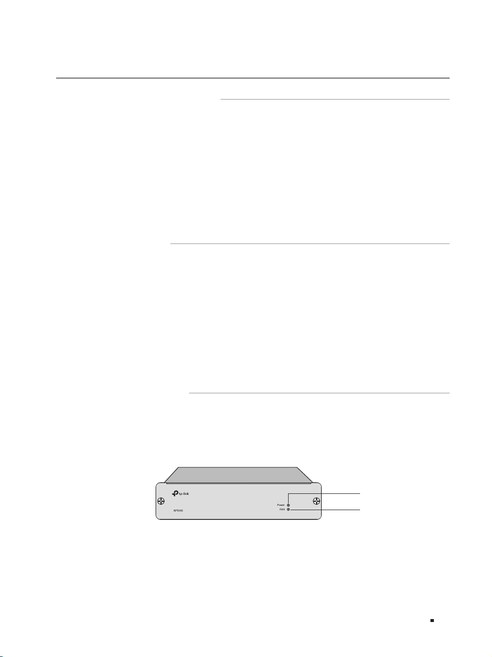
The front panel of RPS150 is shown as the following figure.
Figu re 1-1 Front Panel of R PS150
Power
FAN
Introduction
01
Redundant Power Supply
Indicators
You can monitor the running status of RPS150 through the Power and FAN LEDs.
LED Status Indication
Power
FAN
■
Rear Panel
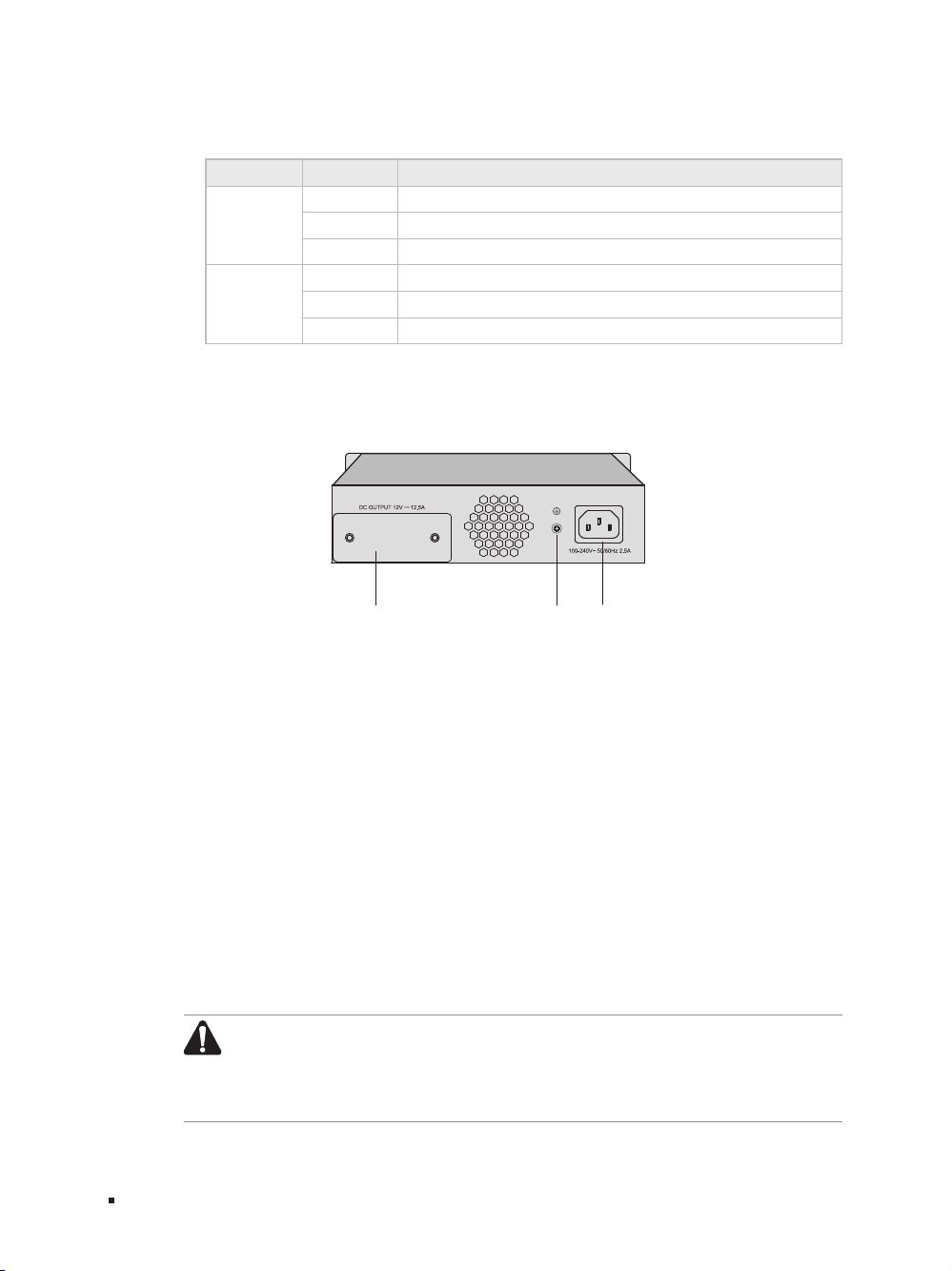
The rear panel of RPS150 is shown as the following figure.
Figu re 1-2 Rear Panel of R PS150
On The system power supply is normal
Flashing The system power supply is abnormal
Off The system power supply is of f or abnormal
On
The fan works normally
Flashing The fan works abnormally
Off The power supply is of f or the fan works abnormally
Protective Cover
Grounding
Terminal
AC Power
Input
AC Power Input
On the right side of the rear panel, and the input AC power should be 100-240V~
50/60Hz.
Grounding Terminal
On the left side of the AC Power Input, please ground the device with the provided
Ground Cable. You can also ground the device through the PE (Protecting Earth)
cable of AC cord. For detailed information, please refer to section 3.1 Connect to
Ground.
Protective Cover
It is used to protect the DC Power Output Socket. Remove it to connect RPS150 to
the powered device.
Caution:
■
Please use the provided power cord and verify the power supply is
100-240V~50/60Hz.
■
The electrical outlet shall be installed near the device and shall be easily
accessible.
02
Introduction

Chapter 2 Installation
2.1 Package Contents
Make sure that the package contains the following items. If any of the listed items is
damaged or missing, please contact your distributor.
Redundant Power Supply
One RPS150
One DC Power Cord and one
AC Power Cord
This Installation Guide
Business Networking Solution
Installation Guide
Four ttings
2.2 Safety Precautions
To avoid any device damage and bodily injury caused by improper use, please observe
the following rules:
■
Safety Precautions
■
Keep the power off during the installation. Wear an ESD-preventive wrist strap, and
make sure that the wrist strap has a good skin contact and is well grounded.
■
Make sure that the input AC power voltage matches the specifications indicated on the
rear panel of the RPS150.
■
Before switching on the power, make sure that the power circuit will not be overloaded,
otherwise the RPS150 will work abnormally or be damaged.
■
Do not open or remove the cover of the RPS150, even if it is not electrified.
■
Before cleaning the device, cut off the power supply. Do not clean it by the waterish
cloth, and never use any other liquid cleaning method.
■
Site Requirements
To ensure normal operation and long service life of the device, please install it in an
environment that meets the requirements described in the following subsection.
Installation
03

Redundant Power Supply
40℃
Temperature/Humidity
Please keep a proper temperature and humidity in the equipment room. Too high/low
humidity may lead to bad insulation, electricity leakage, mechanical property changes
and corrosions. Too high temperature may accelerate aging of the insulation materials
and can thus significantly shorten the service life of the device. For normal temperature
and humidit y of the device, please check the following table.
Environment Temperature Humidity
Operating 0℃ to 40
Storage -40℃ to 70
Clearness
0℃
℃
℃
20% to 90%RH Non-condensing
10% to 95%RH Non-condensing
04
The dust accumulated on the device can be absorbed by static electricity and result
in poor contact of metal contact points. Some measures have been taken for the
device to prevent static electricity, but too strong static electricity can cause deadly
damage to the electronic elements on the internal circuit board. To avoid the effect of
static electricity on the operation of the device, please attach much importance to the
following items:
■
Dust the device regularly, and keep the indoor air clean.
■
Keep the device well grounded and ensure static electricity has been transferred.
Electromagnetic Interference
Electronic elements including capacitance and inductance on the device can be
affected by external interferences, such as conducted emission by capacitance
coupling, inductance coupling, and impedance coupling. To decrease the interferences,
please make sure to take the following measures:
■
Use the power supply that can effectively filter interference from the power grid.
Installation

Redundant Power Supply
■
Keep the device far from high-frequency, strong-current devices, such as radio
transmitting station.
■
Use electromagnetic shielding when necessary.
Lightening Protection
Extremely high voltage currents can be produced instantly when lightning occurs and
the air in the electric discharge path can be instantly heated up to
20,000℃
. As this
instant current is strong enough to damage electronic devices, more effective lightning
protection measures should be taken.
■
Ensure the rack and device are well earthed.
■
Make sure the power socket has a good contact with the ground.
■
Keep a reasonable cabling system and avoid induced lightning.
■
Use the signal SPD (Surge Protective Device) when wiring outdoor.
Note:
For detailed lightning protection measures, please refer to section 3.1 Connect
to Ground.
Installation Site
When installing the device on a rack or a flat workbench, please note the following
items:
■
The rack or workbench is flat and stable, and sturdy enough to support the weight of
5.5kg at least.
■
The rack or workbench has a good ventilation system. The equipment room is well
ventilated.
■
The rack is well grounded. Keep the power socket less than 1.5 meters away from the
device.
Installation
05

Redundant Power Supply
2.3 Installation Tools
■
Phillips Screwdriver
■
ESD-preventive wrist wrap
2.4 Product Installation
The RPS150 can be installed either in a standard 19-inch rack via RPS2 or directly on a
tabletop.
■
Desktop Installation
To install the device on the desktop, please follow the steps:
Caution:
■
Please set 5 to 10cm gaps around the device for heat dissipation and air circulation.
■
Please avoid any heavy thing placed on the device.
1. Set the device upside down on the flat desktop strong enough to support the entire
weight of the device with all fittings.
2. Remove the adhesive backing papers from the supplied rubber feet and attach the
rubber feet to the recessed areas on the bottom at each corner of the device.
Figu re 2-1 Desktop Installation
06
Feet
Bottom of the Device
Notch
3. Turnover the device and place it stably on the tabletop.
■
Rack Installation
RPS150 can be installed in the standard rack via the RPS2 chassis. One RPS2 chassis is
designed to hold up to 2 RPS150s. You should install the RPS2 chassis to the rack first,
and then insert RPS150 into the RPS2. The detailed instructions are described below:
1. Check the grounding and stability of the rack.
2. Place the RPS2 horizontally to an appropriate position in the rack and then support it
with bracket.
Installation

Redundant Power Supply
3. Secure the RPS2 to each side of the fixed guide slot with screws. Verify the stability
and horizontality of RPS2 in the rack.
Figu re 2-2 Inst all the RPS2 to a standard rack
Rack
RPS2
RPS Slot
4. Insert the RPS150 in to the RPS2 and fix it with screws, as illustrated in the figure
below:
Figu re 2-3 Inse rt RPS150 into RP S2
Note:
■
Do not attach the supplied rubber feet on the bottom of RPS150 if it is supposed
to be inserted into RPS2 in the bracket.
■
A well grounded bracket can largely prevent the device from static electricity,
electric leakage, lightning and electromagnetic interference. Make sure the
grounding cable of the bracket is correctly installed.
■
Ensure the device is well ventilated for the purpose of heat dissipation.
Installation
07

Redundant Power Supply
Ground Cable
Grounding Bar
Chapter 3 Connection
3.1 Connect to Ground
Connecting the device to ground is to quickly release the lightning over-voltage and
over-current of the device, which is also a necessary measure to protect the body from
electric shock.
In different environments, the device may be grounded differently. The following
will instruct you to connect the device to the ground in two ways, connecting to the
grounding bar or connecting to the ground via the power cord. Please connect the
device to ground in the optimum way according to your specific operation environment.
■
Connecting to the Grounding Bar
If the device is installed in the Equipment Room, where a grounding bar is available, you
are recommended to connect the device to the grounding bar as shown in the following
figure.
Figu re 3-1 Connecting to the Grounding Bar
Connection
08
Grounding Terminal
RPS150 (Rear Panel)
Note:
The grounding bar and ground cable are not provided with our product. If
needed, please self purchase them.
■
Connecting to the Ground via the Power Supply
If the device is installed in the normal environment, the device can be grounded via the
PE (Protecting Earth) cable of the AC power supply as shown in Figure 3-4.
To connect the device to the ground via the PE (Protecting Ear th) cable of AC power
cord, please make sure the PE (Protecting Earth) cable in the electrical outlet is well
grounded in advance.

Redundant Power Supply
Protective Cover
RPS DC Output
3.2 Connect to the Powered Device
The RPS150 can be used as a redundant backup power supply unit for multiple switch
models. Follow the steps below to connect the RPS150 to a powered device.
1. Confirm that the power supply of the RPS150 is cut off.
2. Remove the protective covers covering the redundant power socket of RPS150 and
the switch. Here we take the removing process of RPS150 for example:
Figu re 3-2 Remov ing the RPS Protective Cover
Removing the Protective Cover
3. Connect the RPS150 and the switch with DC power cord, as illustrated in Figure 3-3.
One end of the DC power cord is marked by the letters “TOP” and the other end has
a positioning card attached to it. Plug the end with the letters “TOP” into the input
socket of the switch with “TOP” facing up and the other end with positioning card
into the DC output socket of the RPS150 with the positioning card facing up.
Caution:
Make sure the power supply of RPS150 is cut off when connecting or
disconnecting RPS150 and the switch, otherwise both RPS150 and the switch
may work abnormally or even be damaged.
Figu re 3-3 Conn ecting to the Powered Swi tch
RPS150
Switch One connector with letters “TOP”
3
Module
TX432
M1
SFP+
4
M2
SFP+
CLASS 1 LASER PRODUCT
Positioning Card
TOP
Power
PS OK
Fault
PSM150-AC
100-240V~ 50/60Hz 2.5A
4
Connection
3
09

Redundant Power Supply
3.3 Power On
The RPS150 requires 100-240V~50/60HZ AC power input.
1. Confirm that the power supply satisfies the requirement of the input voltage of
RP S15 0;
2. Plug the negative connector of the provided AC power cord into the power socket
of RPS150, and the positive connector into a power outlet as the following figure
shown. After RPS150 is powered on normally, the Power LED and FAN LED indicators
on its front panel will light on all the time.
Figu re 3-4 Conn ecting to Power Sup ply
Caution:
■
■
■
3.4 Verify Installation
After completing the installation, please verify the following items:
■
There is enough room around the sides of RPS150 for heat dissipation and the air flow
is adequate;
■
The voltage of the power supply meets the requirement of the input voltage of the
device;
■
The power socket, device and rack are well grounded.
Connection
10
Make sure that the power supply is well grounded. Locate the switch of the power
supply in advance, so that you can cut it off in time when needed.
Disconnect RPS150 from its AC power supply when plugging or removing the DC
power cable.
The figure is to illustrate the application and principle. The power cord you get
from the package and the socket in your situation will comply with the regulation
in your country, so they may differ from the figure above.

Appendix A Specifications
Item Content
AC Power Input 100-240V~ 50/60Hz 2.5A
DC Power Output 12V 12.5A
Maximum Power Output
LEDs Power, FAN
Operating Temperature 0
Storage Temperature -40
Operating Humidity 20%
Storage Humidity 10%
150W
to
40
℃
℃
to
70
℃
℃
to
90%RH Non-condensing
to
95%RH Non-condensing
Redundant Power Supply
11Appendix A Specications

FCC STATEMENT
This equipment has been tested and found to comply with the limits for a Class A digital device,
pursuant to part 15 of the FCC Rules. These limits are designed to provide reasonable protection
against harmful interference when the equipment is operated in a commercial environment. This
equipment generates, uses, and can radiate radio frequency energy and, if not installed and used in
accordance with the instruction manual, may cause harmful interference to radio communications.
Operation of this equipment in a residential area is likely to cause harmful interference in which case
the user will be required to correct the interference at his own expense.
This device complies with part 15 of the FCC Rules. Operation is subject to the following two
conditions:
1) This device may not cause harmful interference.
2) This device must accept any interference received, including interference that may cause
undesired operation.
Any changes or modifications not expressly approved by the party responsible for compliance could
void the user’s authority to operate the equipment.
CE Mark Warning
This is a class A product. In a domestic environment, this product may cause radio interference, in
which case the user may be required to take adequate measures.
Industry Canada Statement
CAN ICES-3 (A)/NMB-3(A)
Korea Warning Statements
당해 무선설비는 운용중 전파혼신 가능성이 있음.
BSMI Notice
安全 諮詢及注意事 項
• 請使用原 裝電源供應器或只能按照 本產品注明的電源類型使用本產品。
• 清潔本產品之前請先拔掉電源線。請勿使用液體、噴霧清潔劑或濕布進行清潔。
• 注意防潮,請勿將水或其他液體潑灑到本產品上。

• 插槽與開口供通 風使 用,以確保本產品的操作可靠並防止 過熱,請勿堵塞 或覆蓋開口。
• 請勿將本產品置放於靠近熱源的地方。除非有正常的通風,否則不可放在密閉位置中。
• 請不要私自打開機殼,不要嘗試自行維修本產品,請由授權的專業人士進行此項工作。
此為甲類資訊技術設備,于居住環境中使用時,可能會造成射頻擾動,在此種情況下,使用者會被要求採取某些適
當的對策。
Продукт сертифіковано згідно с правилами системи УкрСЕПРО на відповідність вимогам
нормативних документів та вимогам, що передбачені чинними законодавчими ак тами України.
Safety Information
• When product has power button, the power button is one of the way to shut off the product; when
there is no power button, the only way to completely shut off power is to disconnect the product
or the power adapter from the power source.
• Don’t disassemble the product, or make repairs yourself. You run the risk of electric shock and
voiding the limited warranty. If you need ser vice, please contact us.
• Avoid water and wet locations.
Explanation of the symbols on the product label
AC voltage.
RECYCLING
This product bears the selective sorting symbol for Waste electrical and electronic
equipment ( WEEE). This means that this product must be handled pursuant to European
directive 2012/19/EU in order to be recycled or dismantled to minimize its impact on the
environment.
User has the choice to give his product to a competent recycling organization or to the
retailer when he buys a new electrical or electronic equipment.


Website: http://www.tp-link.com Tel: +86 755 26504400 E-mail: support@tp-link.com
© 2016 TP-Link
7106506701 REV2.0.0
 Loading...