

Page 1

IN-18
INTRODUCTION
ABBREVIATIONS USED IN THIS MANUAL
For convenience, the following abbreviations are used in this
manual.
ABS Antilock Brake System
A/C Air Conditioner
assy assembly
ECT Electronic Controlled Transmission
ECU Electronic Control Unit
e.g. Exempli Gratia (for Example)
Ex. Except
FWD Front Wheel Drive Vehicles
4WD Four Wheel Drive Vehicles
in. inch
LH Left-hand
LHD Left-hand Drive
MIG Metal Inert Gas
M/Y Model Year
PPS Progressive Power Steering
RH Right-hand
RHD Right-hand Drive
SRS Supplemental Restraint System
SSM Special Service Materials
w/ with
w/o without
Page 2
FOREWORD
This repair manual has been prepared to provide essential information on body panel repair methods (including cutting and
welding operations, but excluding painting) for the SCION xA.
Applicable models: NCP61 series
This manual consists of body repair methods, exploded diagrams and illustrations of the body components and other information relating to body panel replacement such as handling
precautions, etc. However, it should be noted that the front fenders of the SCION model is bolted on and require no welding.
When repairing, don’t cut and join areas that are not shown in
this manual. Only work on the specified contents to maintain
body strength.
Body construction will sometimes differ depending on specifications and country of destination. Therefore, please keep in mind
that the information contained herein is based on vehicles for
general destinations.
For the repair procedures and specifications other than collisiondamaged body components of the SCION xA refer to the repair
manuals.
If you require the above manuals, please contact your SCION
Dealer.
All information contained in this manual is the most up-to-date at
the time of publication. However, specifications and procedures
are subject to change without prior notice.
Page 3

Page 4
Glass Cover
INTRODUCTION
GENERAL REPAIR INSTRUCTIONS
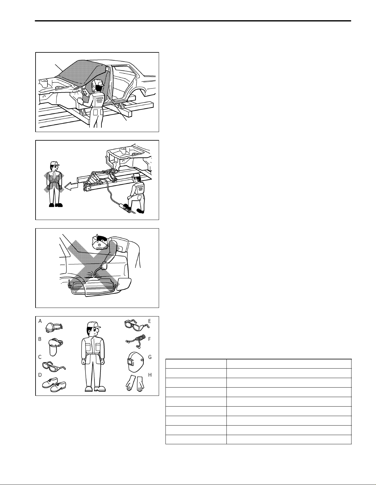
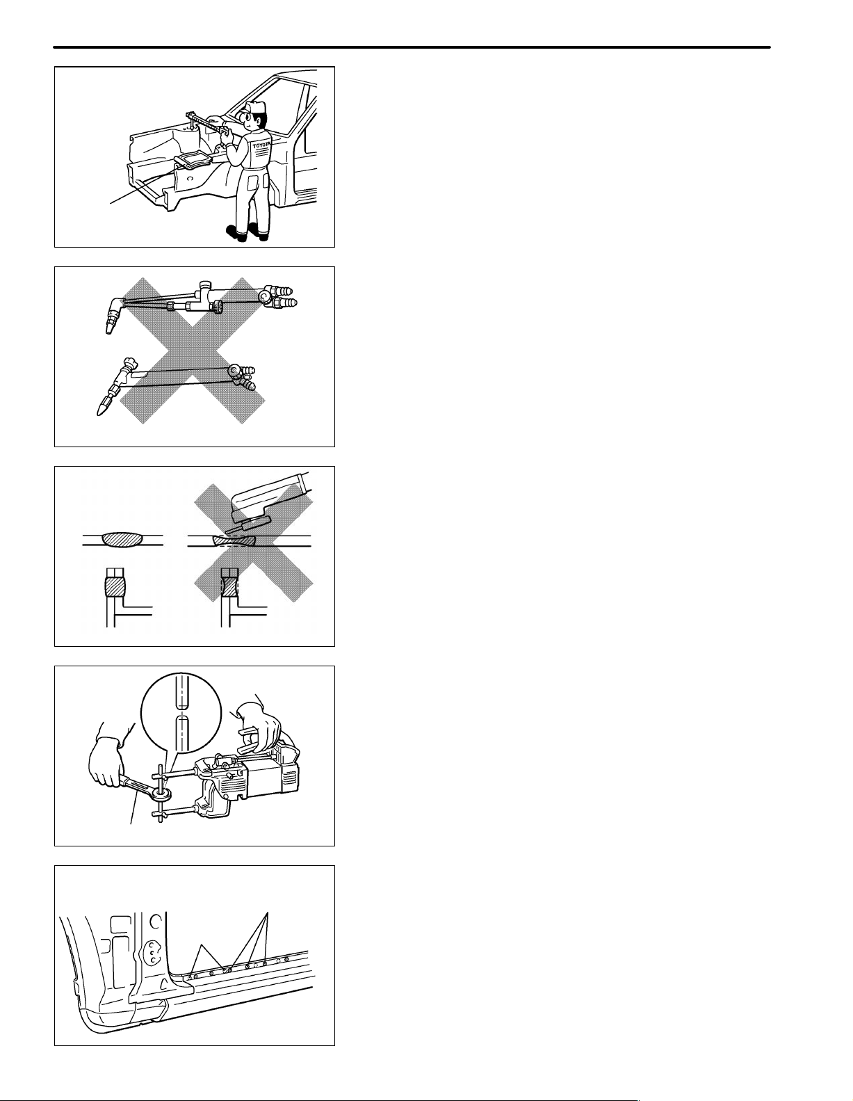
1. WORK PRECAUTIONS
(a) VEHICLE PROTECTION
(1) When welding, protect the painted surfaces, windows,
seats and carpet with heat resistant, fire-proof covers.
IN-1
WRONG
Seat Cover
F10001A
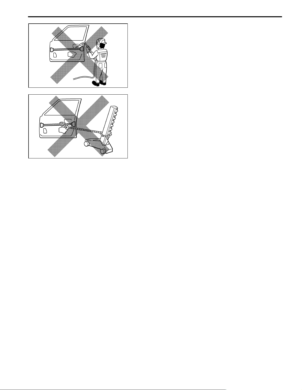
(b) SAFETY
(1) Never stand in direct line with the chain when using a
puller on the body or frame, and be sure to attach a
safety cable.
F10002A
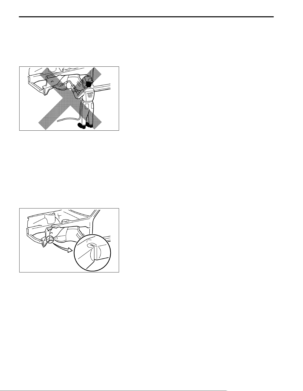
(2) Before performing repair work, check for fuel leaks.
If a leak is found, be sure to close the opening totally.
(3) If it is necessary to use a flame in the area of the fuel
tank, first remove the tank and plug the fuel line.
WRONG
F10003A
F10004
(c) SAFETY WORK CLOTHES
(1) In addition to the usual mechanic’s wear, cap and
safety shoes, the appropriate gloves, head protector,
glasses, ear plugs, face protector, dust-prevention
mask, etc. should be worn as the situation demands.
Code Name
A Dust-Prevention Mask
B Face Protector
C Eye Protector
D Safety Shoes
E Welder’s Glasses
F Ear Plugs
G Head Protector
H Welder’s Gloves
Page 5

IN-2
INTRODUCTION
2. HANDLING PRECAUTIONS OF PLASTIC BODY PARTS
(1) The repair procedure for plastic body parts must conform with the type of plastic material.
(2) Plastic body parts are identified by the codes in the following table.
(3) When repairing metal body parts adjoining plastic body parts (by brazing, frame cutting, welding, paint-
ing etc.), consideration must be given to the property of the plastic.
*
Heat
Code
Material
name
resistant
temperature
limit C (F)
Resistance to
alcohol or gasoline
Notes
AAS
ABS
AES
ASA
CAB
EPDM
FRP
Acrylonitrile
Acrylic Styrene
Acrylonitrile
Butadiene Styrene
Acrylonitrile
Ethylene Styrene
Acrylonitrile
Styrene
Acrylate
Cellulose
Acetate
Ethylene
Propylene
Fiber
Reinforced
Plastics
80
(176)
80
(176)
80
(176)
80
(176)
80
(176)
100
(212)
180
(356)
Alcohol is harmless if applied only for
short time in small amounts (e.g., quick
wiping to remove grease).
Alcohol is harmless if applied only for
short time in small amounts (e.g., quick
wiping to remove grease).
Alcohol is harmless if applied only for
short time in small amounts (e.g., quick
wiping to remove grease).
Alcohol is harmless if applied only for
short time in small amounts (e.g., quick
wiping to remove grease).
Alcohol is harmless if applied only for
short time in small amounts (e.g., quick
wiping to remove grease).
Alcohol is harmless.
Gasoline is harmless if applied only for
short time in small amounts.
Alcohol and gasoline are harmless. Avoid alkali.
Avoid gasoline and organic
or aromatic solvents.
Avoid gasoline and organic
or aromatic solvents.
Avoid gasoline and organic
or aromatic solvents.
Avoid gasoline and organic
or aromatic solvents.
Avoid gasoline and organic
or aromatic solvents.
Most solvents are harmless
but avoid dipping in gasoline,
solvents, etc.
EVA
PA
PBT
PC Polycarbonate
*Temperatures higher than those listed here may result in material deformation during repair.
Ethylene
Acetate
Polyamide
(Nylon)
Polybutylene
Terephthalate
70
(158)
80
(176)
160
(320)
120
(248)
Alcohol is harmless if applid only for short
time in small amounts (e.g., quick wiping
to remove grease).
Alcohol and gasoline are harmless. Avoid battery acid.
Alcohol and gasoline are harmless. Most solvents are harmless.
Alcohol is harmless.
Avoid gasoline and organic
or aromatic solvents.
Avoid gasoline brake fluid,
wax, wax removers and
organic solvents. Avoid alkali.
Page 6

Code
Material
name
*
Heat
resistant
temperature
limit C (F)
INTRODUCTION
Resistance to
alcohol or gasoline
IN-3
Notes
PE Polyethylene
PET
PMMA
POM
PP Polypropylene
PPO
PS Polystyrene
PUR Polyurethane
Polyethylene
Terephthalate
Polymethyl
Methacrylate
Polyoxymethylene
(Polyacetal)
Modified
Polyphenylene
Oxide
80
(176)
75
(167)
80
(176)
100
(212)
80
(176)
100
(212)
60
(140)
80
(176)
Alcohol and gasoline are harmless. Most solvents are harmless.
Alcohol and gasoline are harmless. Avoid dipping in water.
Alcohol is harmless if applied only for
short time in small amounts.
Alcohol and gasoline are harmless. Most solvents are harmless.
Alcohol and gasoline are harmless. Most solvents are harmless.
Alcohol is harmless.
Alcohol and gasoline are harmless if
applied only for short time in small
amounts.
Alcohol is harmless if applied only for very
short time in small amounts (e.g., quick
wiping to remove grease).
Avoid dipping or immersing
in alcohol, gasoline,
solvents, etc.
Gasoline is harmless if
applied only for quick wiping
to remove grease.
Avoid dipping or immersing
in alcohol, gasoline,
solvents, etc.
Avoid dipping or immersing
in alcohol, gasoline,
solvents, etc.
Alcohol and gasoline are harmless if
PVC
SAN
TPO
TPU
TSOP
UP
*Temperatures higher than those listed here may result in material deformation during repair.
Polyvinylchloride
(Vinyl)
Styrene
Acrylonitrile
Thermoplastic
Olefine
Thermoplastic
Polyurethane
TOYOTA
Super
Olefine Polymer
Unsaturated
Polyester
80
(176)
80
(176)
80
(176)
80
(176)
80
(176)
110
(233)
applied only for short time in small
amounts (e.g., quick wiping to remove
grease).
Alcohol is harmless if applied only for
short time in small amounts (e.g., quick
wiping to remove grease).
Alcohol is harmless.
Gasoline is harmless if applied only for
short time in small amounts.
Alcohol is harmless if applied only for
short time in small amounts (e.g., quick
wiping to remove grease).
Alcohol and gasoline are harmless. Most solvents are harmless.
Alcohol and gasoline are harmless. Avoid alkali.
Avoid dipping or immersing
in alcohol, gasoline,
solvents, etc.
Avoid dipping or immersing
in alcohol, gasoline, solvents
etc.
Most solvents are harmless
but avoid dipping in gasoline,
solvents, etc.
Avoid dipping or immersing
in alcohol, gasoline,
solvents, etc.
Page 7

IN-4
INTRODUCTION
3. LOCATION OF PLASTIC BODY PARTS
Parts Name Code
Radiator Grille TSOP
Front Bumper Cover TSOP
Front Bumper Hole Cover TSOP
Headlight PP/PC
Fog light TSOP
Side Turn Signal Light PMMA/ABS
Fender Panel Mudguard TSOP
Front Fender Mudguard PP/EPDM
Cowl Top Ventilator Louver TSOP
Outer Rear View Mirror ABS/PA
Front Pillar Upper Cover AES
Side Mudguard TSOP
Front Door Outside Handle PC/PA
Rear Door Outside Handle PC/PA
Quarter Panel Rear Mudguard TSOP
Rear Wheel House Plate PP/EPDM
Back Door Outside Garnish ABS
Back Door Outside Handle PA
High Mount Stop Light PMMA/ABS
Rear Bumper Cover TSOP
Rear Combination Light PMMA/AAS
License Plate Light PMMA/ABS
Rear Fog Light PC/ABS
Rear Spoiler ABS
Resin material differs with model.
/ Made up of 2 or more kinds of materials.
Page 8
INTRODUCTION
HANDLING PRECAUTIONS ON RELATED COMPONENTS
1. BRAKE SYSTEM
The brake system is one of the most important safety components. Always follow the directions and
notes given in brake (32) section of the repair manual for the relevant model when handling brake system
parts.
NOTICE: When repairing the brake master cylinder or TRAC system, bleed the air out of the TRAC system.
2. DRIVE TRAIN AND CHASSIS
The drive train and chassis are components that can have great effects on the running performance and
vibration resistance of the vehicle. After installing components in the sections listed in the table below,
perform alignments to ensure correct mounting angles and dimensions. Particularly accurate repair of
the body must also be done to ensure correct alignment.
HINT: Correct procedures and special tools are required for alignment. Always follow the directions given in the repair manual for the relevant model during alignment and section DI of this section.
IN-15
Component to be aligned
Front Wheels Front Suspension (26) section
Rear Wheels Rear Suspension (27) section
Section of repair manual
for relevant model
3. COMPONENTS ADJACENT TO THE BODY PANELS
Various types of component parts are mounted directly on or adjacently to the body panels. Strictly observe the following precautions to prevent damaging these components and the body panels during handling.
Before repairing the body panels, remove their components or apply protective covers over the com-
ponents.
Before prying components off using a screwdriver or a scraper, etc., attach protective tape to the tool
tip or blade to prevent damaging the components and the body paint.
Before removing components from the outer surface of the body, attach protective tape to the body to
ensure no damage to painted areas.
HINT: Apply touch-up paint to any damaged paint surfaces.
Before drilling or cutting sections, make sure that there are no wires, etc. on the reverse side.
4. ECU (ELECTRONIC CONTROL UNIT)
Many ECUs are mounted in this vehicle.
Take the following precautions during body repair to prevent damage to the ECUs.
Before starting electric welding operations, disconnect the negative (-) terminal cable from the bat-
tery.
When the negative (-) terminal cable is disconnected from the battery , memory of the clock and audio
systems will be cancelled. So before starting work, make a record of the contents memorized by each
memory system. Then when work is finished, reset the clock and audio systems as before.
When the vehicle has tilt and telescopic steering, power seat and outside rear view mirror, which are
all equipped with memory function, it is not possible to make a record of the memory contents.
So when the operation is finished, it will be necessary to explain this fact to the customer, and request
the customer to adjust the features and reset the memory.
Do not expose the ECUs to ambient temperatures above 80C (176F).
NOTICE: If it is possible the ambient temperature may reach 80C (176F) or more, remove the ECUs
from the vehicle before starting work.
Be careful not to drop the ECUs and not to apply physical shocks to them.
Page 9
INTRODUCTION
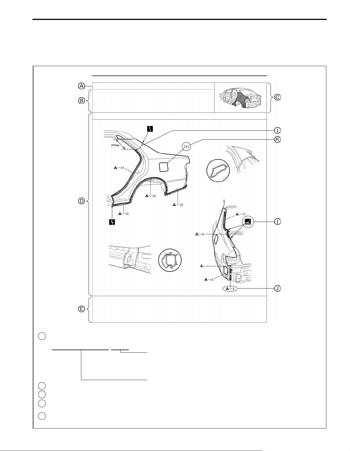
HOW TO USE THIS MANUAL
1. BODY PANEL REPLACEMENT THIS MANUAL
IN-5
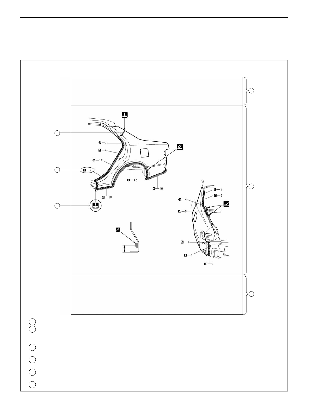
BP-34
QUARTER PANEL (CUT)
REPLACEMENT
REMOVAL
BODY PANEL REPLACEMENT
POINT
1 Remove the [A] at the same time.
PART NAME
[A] Fuel Filler Opening Lid
:
REPLACEMENT PART AND METHOD
A
QUARTER PANEL (CUT)
Replacement method
(ASSY) ... Assembly replacement
(CUT) ... Major cutting (less than 1/2 of part used)
(CUT-H) ... Half cutting (about 1/2 of part used)
(CUT-P) ... Partial cutting (most of part used)
:
REMOVAL CONDTIONS
B
:
PART LOCATION
C
:
REMOVAL DIAGRAM
D
Describes in detail removal of the damaged part involving repair by cutting.
:
REMOVAL GUIDE
E
Provides additional information to more efficiently help you perform the removal.
Replacement part
F13890A
Page 10
IN-6
INTRODUCTION
BODY PANEL REPLACEMENT BP-35
INSTALLATION
Temporaily install the new parts and measure each part of the new parts in accordance with the body dimension
diagram. (See the body dimension diagram)
Inspect the fiting of the related parts around the new parts before welding. This affects the appearance of the
finish.
After welding, apply the polyurethane foam to the corresponding parts.
After welding, apply body sealer and under-coating to the corresponding parts.
After applying the top coat layer, apply anti-rust agent to the inside of the necked section structural weld spots.
I
F
J
G
I
5mm
POINT
1 Before temporarily installing the new parts, apply body sealer to the wheel arch.
HINT:
1) Apply body sealer about 5mm (0.20in.) front the flange, avoiding any oozing.
2) Apply sealer evenly, about 3 - 4mm (0.12 - 0.16in.) in diameter.
3) For other sealing points, refer to section PC.
PART NAME
[A] Fuel Filler Opening Lid [B] Waterproof Rivet
H
:
INSTALLATION CONDITIONS
F
:
INSTALLATION DIAGRAM
G
Describes in detail installation to the new part involving repair by welding and/or
cutting, but excluding painting.
:
INSTALLATIOLN GUIDE
H
Provides additional information to more efficiently help you perform the installation.
:
SYMBOLS
I
(See page IN-7)
:
ILLUSTRATION OF WELD POINTS
J
Weld method and panel position symbols (See page IN-9)
:
PART NAME
K
F13891A
Page 11
INTRODUCTION
IN-7
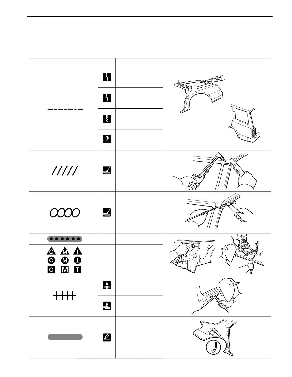
2. SYMBOLS
The following symbols are used in the welding diagrams in section BP of this manual to indicate cutting areas
and the types of weld required.
SYMBOLS MEANING ILLUSTRATION
CUT AND JOIN LOCATION
(SAW CUT)
CUT AND JOIN LOCATION
(Cut Location for
Supply Parts)
CUT LOCATION
CUT WITH DISC
SANDER, ETC.
—
—
BRAZE
(Removal)
BRAZE
(Installation)
WELD POINTS
SPOT WELD OR
MIG PLUG WELD
(See Page IN-9)
CONTINUOUS
MIG WELD
(BUTT WELD)
CONTINUOUS
MIG WELD
(TACK WELD)
BODY SEALER
F13893A
Page 12
IN-8
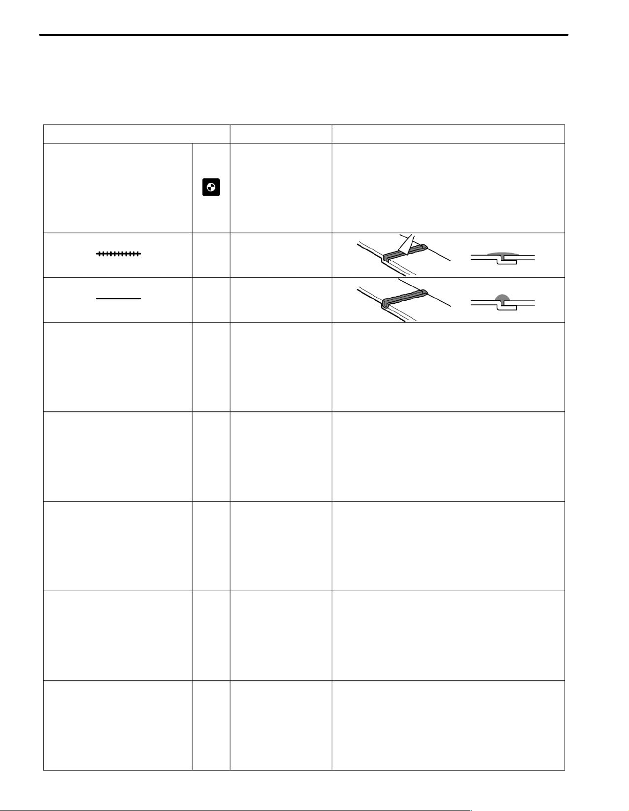
INTRODUCTION
SYMBOLS MEANING ILLUSTRATION
—
—
—
Assembly Mark
BODY SEALER
(Flat Finishing)
BODY SEALER
(No flat Finishing)
F13894A
Page 13
INTRODUCTION
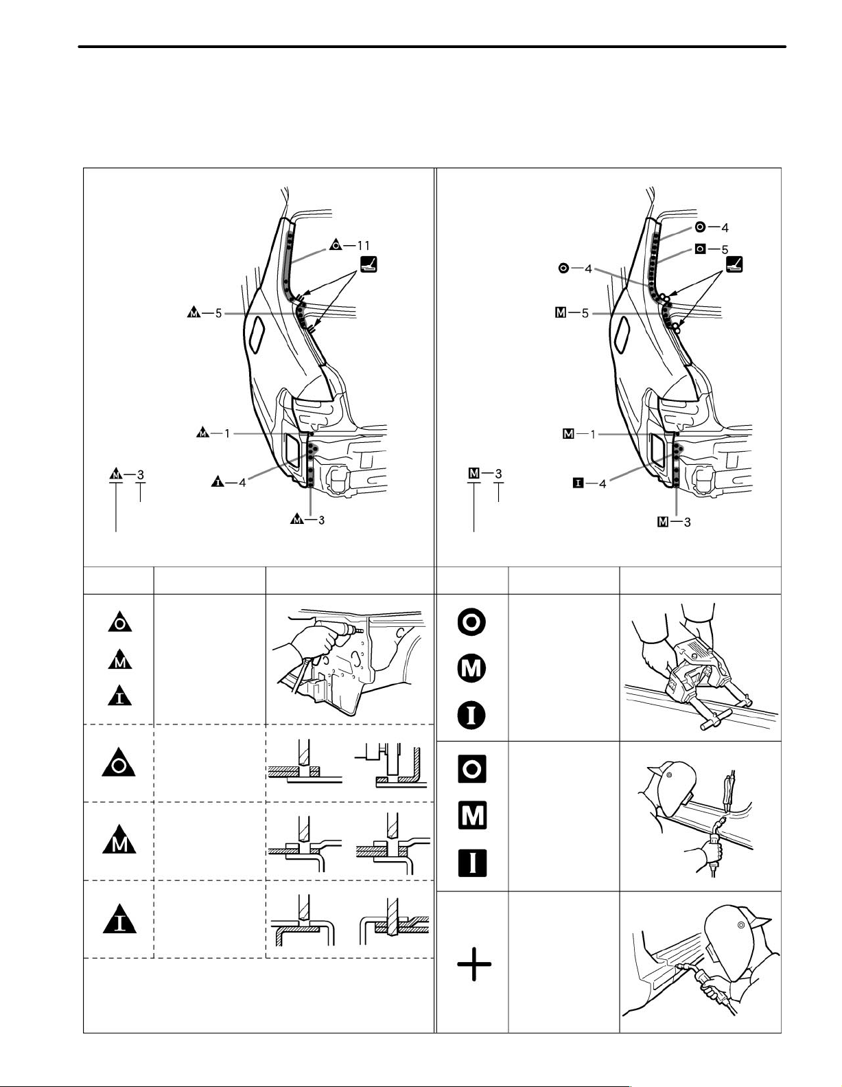
3. ILLUSTRATION OF WELD POINT SYMBOLS
EXAMPLE:
REMOVAL INSTALLATION
IN-9
Weld points
Remove weld point and panel position
SYMBOLS
MEANING ILLUSTRATION SYMBOLS MEANING ILLUSTRATION
Remove
Weld
Points
(Outside)
(Middle)
Weld points
Weld method and panel position
Spot Weld
MIG Plug
Weld
(Inside)
HINT: Panel position symbols are as seen from
the working posture.
Spot MIG
Weld
F13892A
Page 14
IN-16
INTRODUCTION
PRECAUTIONS FOR REPAIRING BODY
STRUCTURE PANELS
1. HEAT REPAIR FOR BODY STRUCTURE
PANELS
Toyota prohibits the use of the heat repair method on body
structure panels when repairing a vehicle damaged in a collision.
Panels that have high strength and rigidity, as well as a long
life span for the automobile body are being sought after.
At Toyota, in order to fulfill these requirement, we use high
tensile strength steel sheets and rust preventive steel
sheets on the body.
High tensile steel sheets are made with alloy additives and
a special heat treatment in order to improve the strength.
To prevent the occurrence of rust for a long period of time,
the surface of the steel is coated with a zinc alloy.
If a body structure parts are heat repaired with an acetylene
torch or ot h e r heating source, the crystalline organization of
the steel sheet will change and the strength of the steel
sheet will be reduced.
The ability of the body to resist rust is significantly lowered
as well since the rust resistant zinc coating is destroyed by
heat and the steel sheet surface is oxidized.
2. STRUCTURE PANEL KINKS
A sharp deformation angle on the panel that cannot be returned to its original shape by pulling or hammering is
called a kink.
Since structure parts were designed to exhibit a 100% performance when they were in their original shape, if they are
deformed in an accident, or if the deformed parts are repaired and reused, they become unable to exhibit the same
performance as intended in the design.
It is necessary to replace the part where the kink has occurred.
Page 15
INTRODUCTION
3. IMPACT BEAM REPAIR
The impact beam and bracket are necessary and important
parts in maintaining a survival space for passengers in a
side collision.
For impact beam, we use special high tensile strength
steel.
The high tensile strength steel maintains its special crystalline organization by heat treatment or alloy additives.
Since these parts were designed to exhibit a 100% performance when they were in their original shape, if they are
deformed in an accident, or if the deformed parts are repaired and reused, they become unable to exhibit the same
performance as intended in the design.
It is necessary to replace the door assembly when impact
beam or bracket is damaged.
IN-17
Page 16
IN-10
Cutting Okay
Reinforcement
INTRODUCTION
PROPER AND EFFICIENT WORK
PROCEDURES
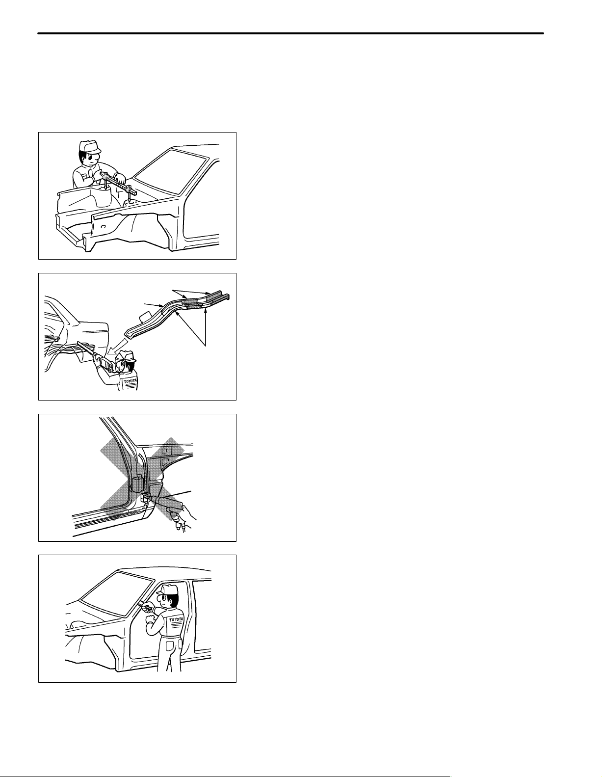
1. REMOVAL
(a) PRE-REMOVAL MEASURING
(1) Before removal or cutting operations, take measure-
ments in accordance with the dimension diagram. Always use a puller to straighten a damaged body or
frame.
F10007
(b) CUTTING AREA
(1) Always cut in a straight line and avoid reinforced area.
WRONG
Corners
F10008A
(c) PRECAUTIONS FOR DRILLING OR CUTTING
(1) Check behind any area to be drilled or cut to insure
that there are no hoses, wires, etc., that may be damaged.
HINT: See “Handling Precautions on Related Components” on page IN-15.
F10009A
(d) REMOVAL OF ADJACENT COMPONENTS
(1) When removing adjacent components, apply protec-
tive tape to the surrounding body and your tools to prevent damage.
HINT: See “Handling Precautions on Related Components” on page IN-15.
F10010
Page 17
Less than
3mm
F10011A
F10012
INTRODUCTION
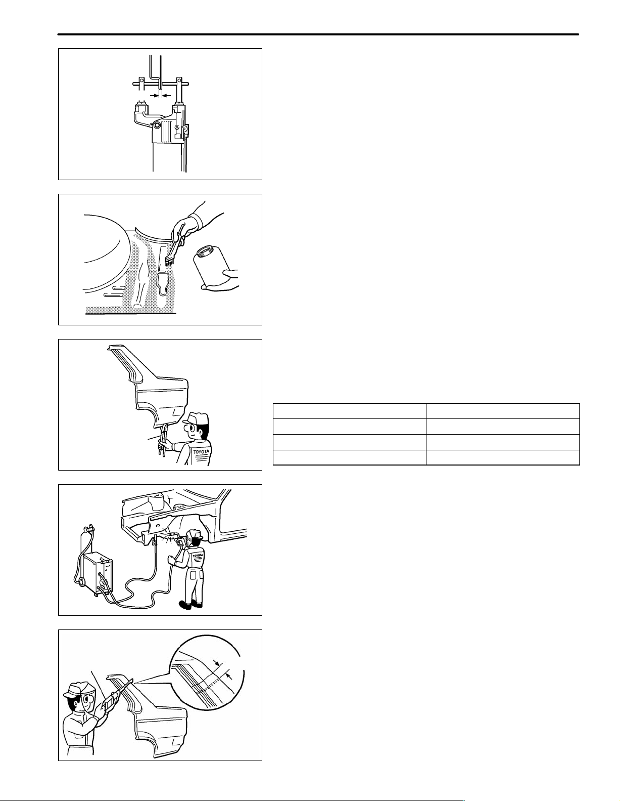
2. PREPARATION FOR INST ALLATION
(a) SPOT WELD POINTS
(1) When welding panels with a combined thickness of
over 3mm (0.12in.), use a MIG (Metal Inert Gas) welder for plug welding.
HINT: Spot welding will not provide sufficient durability
for panels over 3mm (0.12in.) thick.
(b) APPLICATION OF WELD-THROUGH PRIMER
(SPOT SEALER)
(1) Remove the paint from the portion of the new parts
and body to be welded, and apply weld-through primer.
IN-11
Air Saw
Puncher
20 30mm
F10013A
F10014
Overlap
(c) MAKING HOLES FOR PLUG WELDING
(1) For areas where a spot welder cannot be used, use a
puncher or drill to make holes for plug welding.
REFERENCE: mm (in.)
Thickness of welded portion Size of plug hole
1.0 (0.04) under 5 (0.20) ø over
1.0 (0.04) - 1.5 (0.06) 6.4 (0.26) ø over
1.5 (0.06) over 8 (0.31) ø over
(d) SAFETY PRECAUTIONS FOR ELECTRICAL COM-
PONENTS
(1) When welding, there is a danger that electrical compo-
nents will be damaged by the electrical current flowing
through the body.
(2) Before starting work, disconnect the negative terminal
of the battery and ground the welder near the welding
location of the body.
(e) ROUGH CUTTING OF JOINTS
(1) For joint areas, rough cut the new parts, leaving 20 -
30mm (0.79 - 1.18in.) overlap.
F10015A
Page 18
IN-12
Body
Measurement
Diagrams
INTRODUCTION
3. INSTALLATION
(a) PRE-WELDING MEASUREMENTS
(1) Always take measurements before installing under-
body or engine components to insure correct assembly. After installation, confirm proper fit.
F10016A
(b) WELDING PRECAUTIONS
(1) The number of welding spots should be as follows.
Spot weld: 1.3 X No. of manufacturer’s spots.
Plug weld: More than No. of manufacturer’s plugs.
(2) Plug welding should be done with a MIG (Metal Inert
Gas) welder. Do not gas weld or braze panels at areas
other than specified.
WRONG
CORRECT WRONG
Tip Cutter
F10017A
(c) POST-WELDING REFINISHING
(1) Always check the welded spots to insure they are se-
cure.
(2) When smoothing out the weld spots with a disc grind-
er, be careful not to grind off too much as this would
weaken the weld.
F10018A
(d) SPOT WELD LOCATIONS
(1) Try to avoid welding over previous spots.
F10019A
Old
Spot
Locations
New Spot
Locations
F10020A
(e) SPOT WELDING PRECAUTIONS
(1) The shape of the welding tip point has an effect on the
strength of the weld.
(2) Always insure that the seams and welding tip are free
of paint.
Page 19
INTRODUCTION
IN-13
Sealer Gun
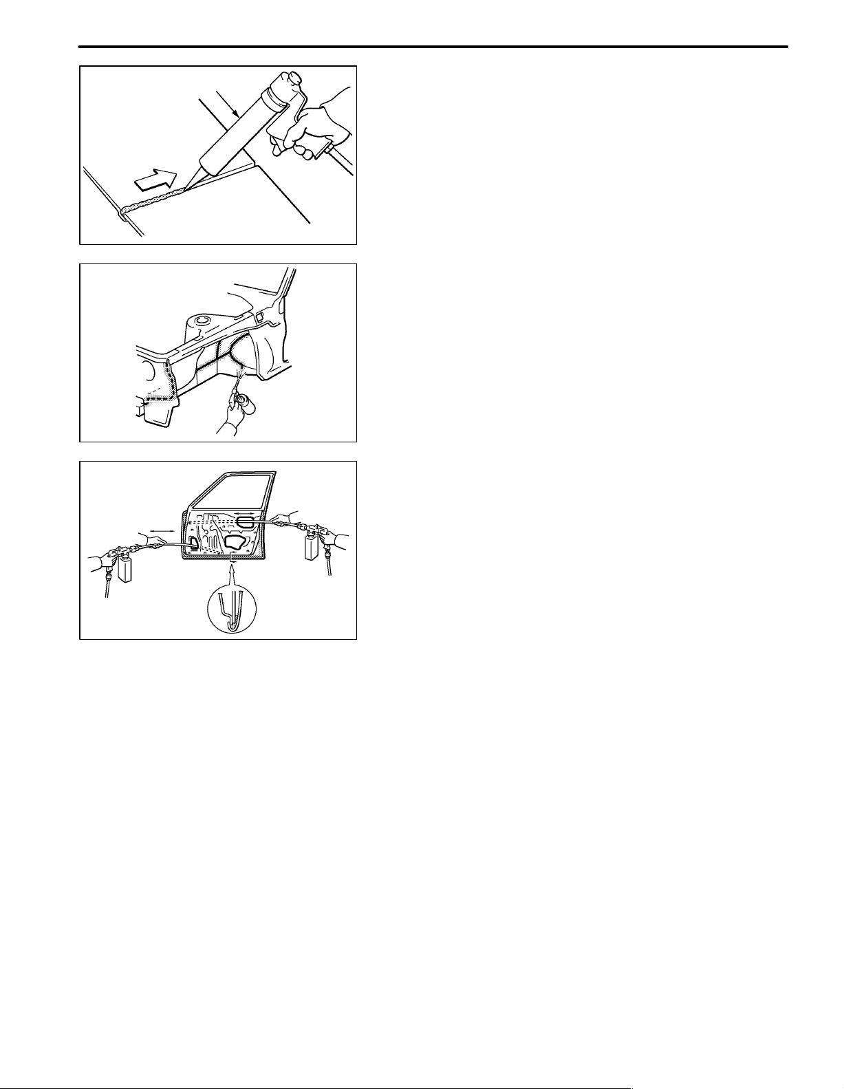
4. ANTI-RUST TREATMENT
(a) BODY SEALER APPLICATION
(1) For water-proofing and anti-corrosion measures, al-
ways apply the body sealer to the body panel seams
and hems of the doors, hoods, etc.
F10021A
(b) UNDERCOAT APPLICATION
(1) To prevent corrosion and protect the body from dam-
age by flying stones, always apply sufficient undercoat to the bottom surface of the under body and inside of the wheel housings.
F10022
5. ANTI-RUST TREATMENT AFTER PAINTING
PROCESS
(a) ANTI-RUST AGENT (WAX) APPLICATION
(1) To preserve impossible to paint areas from corrosion,
always apply sufficient anti-rust agent (wax) to the inside of the hemming areas of the doors and hoods,
and around the hinges, or the welded surfaces inside
the boxed cross-section structure of the side member,
body pillar, etc.
F10023
Page 20
IN-14
INTRODUCTION
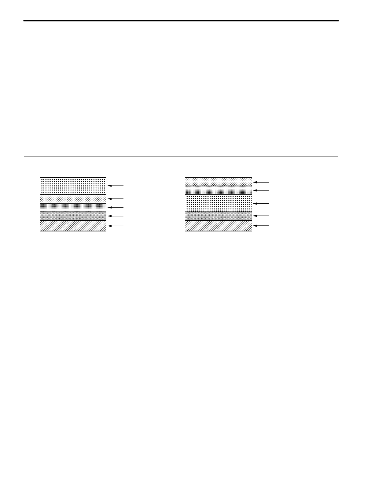
6. ANTI-RUST TREATMENT BY PAINTING
REFERENCE:
Painting prevents corrosion and protect the sheet
metal from damage. In this section, anti-chipping paint
only for anti-corrosion purpose is described.
(a) ANTI-CHIPPING PAINT
(1) To prevent corrosion and protect the body from dam-
age by flying stones, etc., apply anti-chipping paint to
the rocker panel, wheel arch areas, balance panel,
etc.
HINT:
Depending on the model or the application area, there
are cases where the application of anti-chipping paint
is necessary before the second coat or after the top
coat.
Apply the anti-chipping paint after
the top coat.
Anti-Chipping Paint
Top Coat
Second Coat
Under Coat (ED Primer)
Steel Metal
Apply the anti-chipping paint before
the second coat.
Top Coat
Second Coat
Anti-Chipping Paint
Under Coat (ED Primer)
Steel Metal
F10024A
Page 21
VIEWS OF THIS TEXT
Scope of the repair work explanation
This text explains the welding panel replacement instructions from the vehicle’ s white body condi-
tion. W e have abbreviated the explanations of the removal and reinstallation of the equipment parts
up to the white body condition and of the installation, inspection, adjustment and final inspection of
equipment parts after replacing the weld panel.
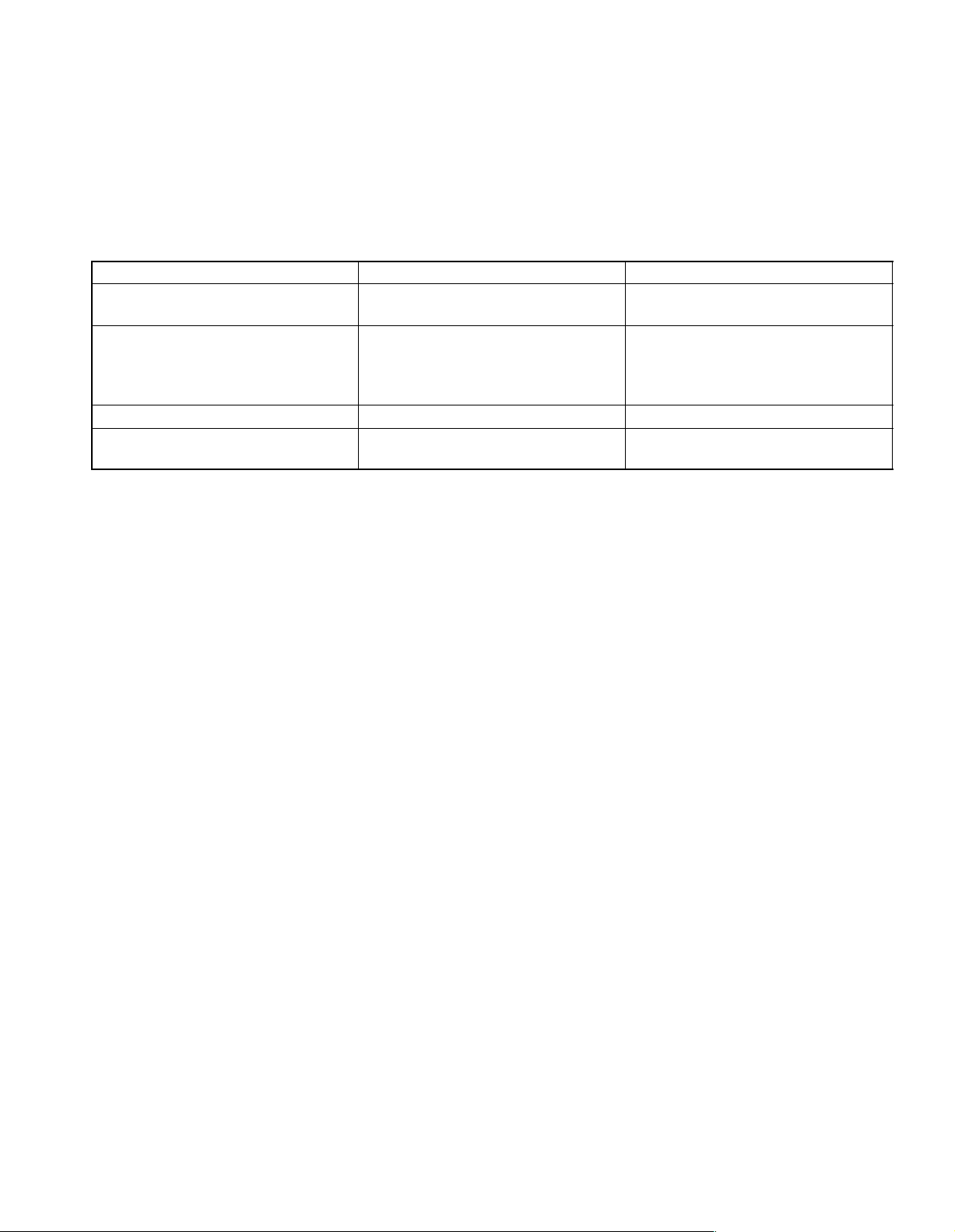
Section categories
Each section has been divided as shown below.
Section Title Contents Examples
INTRODUCTION
BODY PANEL REPLACEMENT
BODY DIMENSIONS Body aligning measurements. Dimension diagrams.
PAINT COATING
Explanation of general body repair.
Views of weld panel replacement instructions.
Instructions for replacing the weld panels
from the white body condition, from which
bolted parts have been removed, with
individual supply parts.
Scope and type of anti-rust treatment, etc.
together with weld panel replacement.
Abbreviation of contents in this text.
The following essential procedures have been abbreviated. When actually working, conduct this
work properly.
(1) Jack and lift operations.
(2) Clean and wash removed parts, if necessary.
(3) Visual inspection.
Cautionary items.
Views of weld panel replacement instructions.
Front side member replacement.
Quarter panel replacement.
Under coat.
Body sealer.
Page 22

Page 23
BP-40
BODY PANEL REPLACEMENT
BACK DOOR OPENING TROUGH (ASSY)
REPLACEMENT
With the body lower back panel removed.
REMOVAL
F15540A
POINT
1 Remove the [A] at the same time.
PART NAME
[A] Back door Opening Lower Reinforcement
F15540
Page 24
BODY PANEL REPLACEMENT
BP-41
INSTALLATION
Temporarily install the new parts and measure each part of the new parts in accordance with the body dimension
diagram. (See the body dimension diagram)
Inspect the fitting of the related parts around the new parts before welding. This affects the appearance of the
finish.
After welding, apply the polyurethane foam to the corresponding parts.
After welding, apply body sealer and under-coating to the corresponding parts.
After applying the top coat layer, apply anti-rust agent to the inside of the necked section structural weld spots.
F15541
POINT
1 Inspect the fitting of the back door and rear combination light, etc., before welding, since this affects the ap-
pearance of the finish.
PART NAME
[A] Back Door Opening Lower Reinforcement
[B] Rear Bumper Upper Side Retainer
Page 25
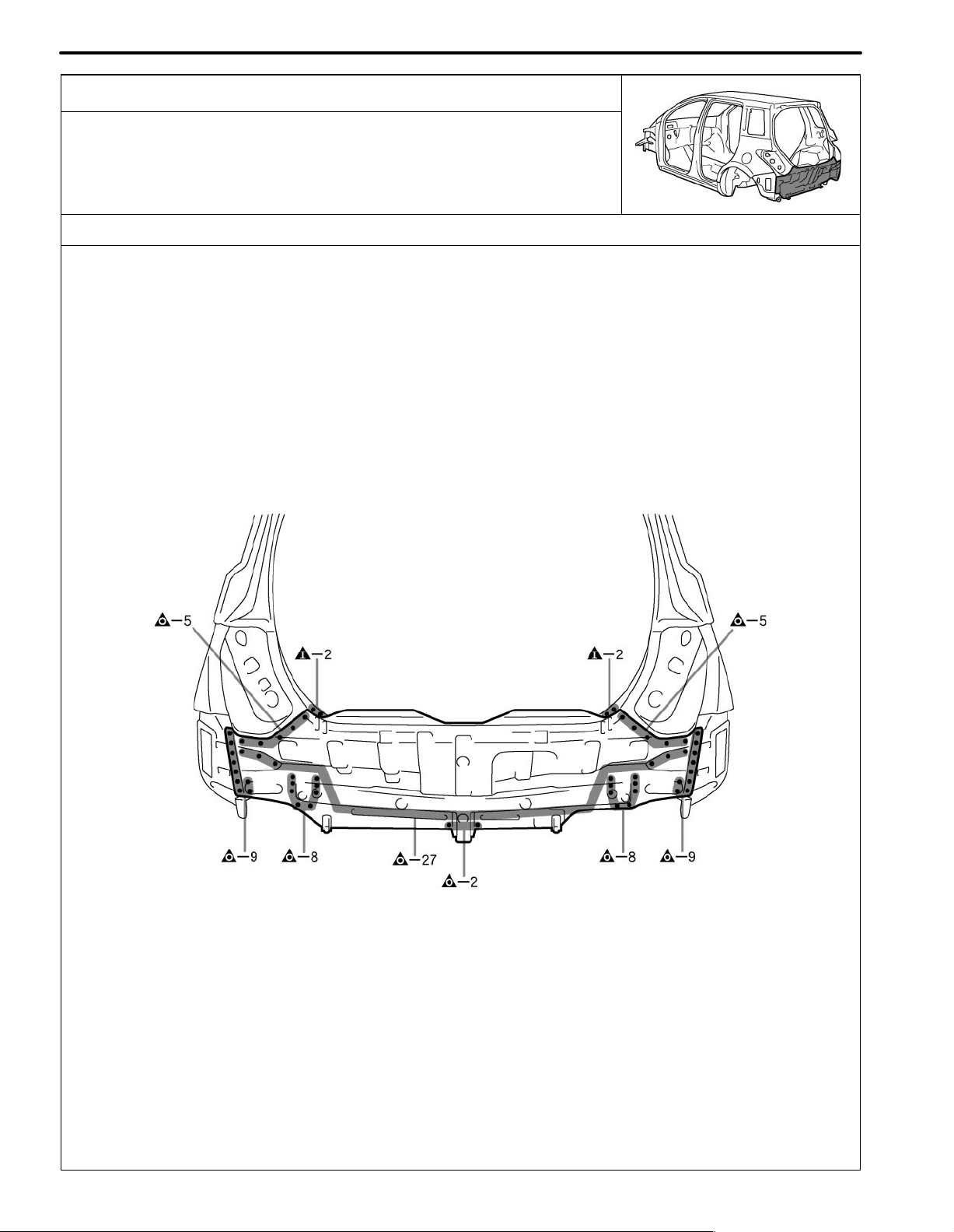
BP-38
BODY PANEL REPLACEMENT
BODY LOWER BACK PANEL (ASSY)
REPLACEMENT
REMOVAL
F15538A
F15538
Page 26
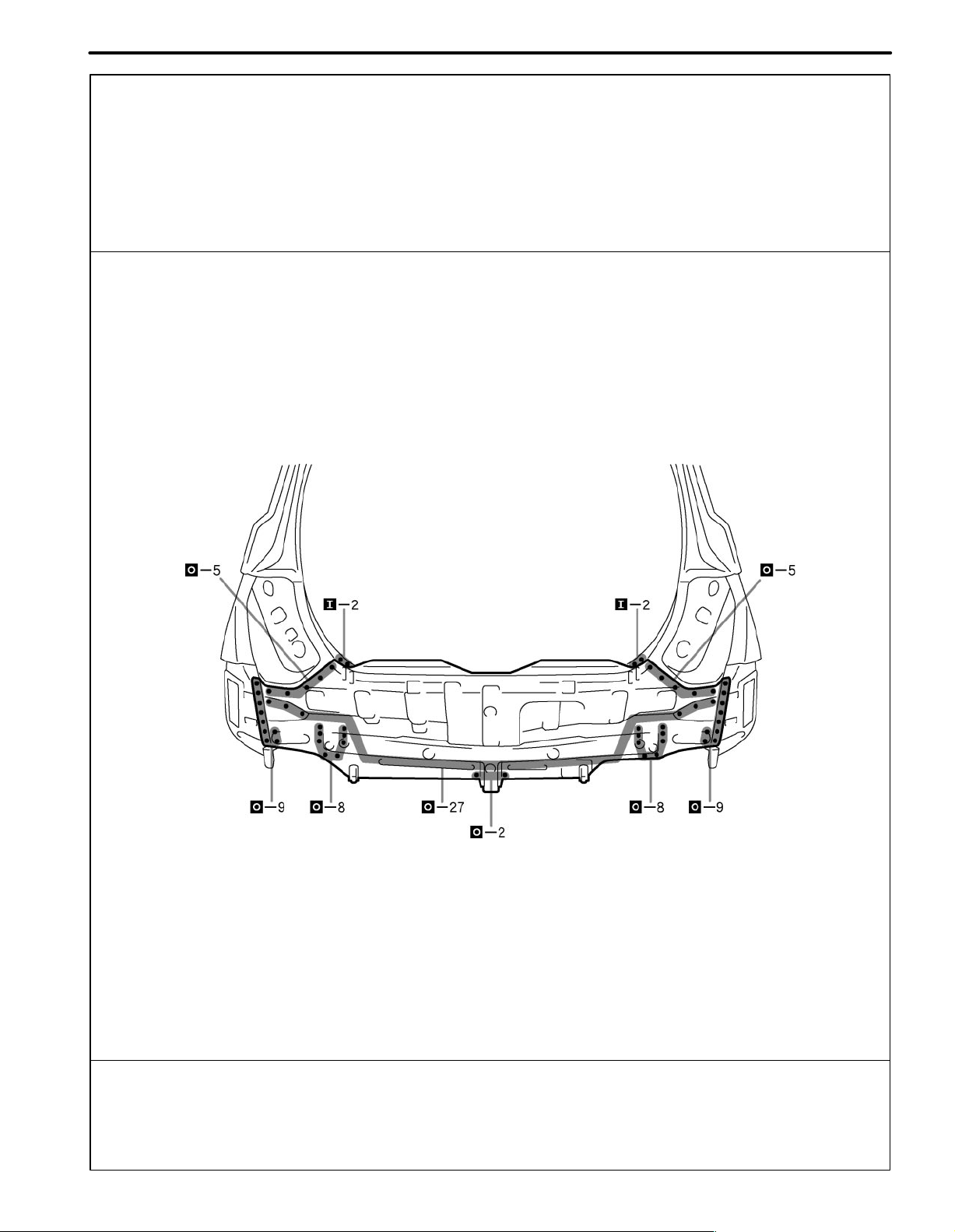
BODY PANEL REPLACEMENT
BP-39
INSTALLATION
Temporarily install the new parts and measure each part of the new parts in accordance with the body dimension
diagram. (See the body dimension diagram)
Inspect the fitting of the related parts around the new parts before welding. This affects the appearance of the
finish.
After welding, apply the polyurethane foam to the corresponding parts.
After welding, apply body sealer and under-coating to the corresponding parts.
After applying the top coat layer, apply anti-rust agent to the inside of the necked section structural weld spots.
F15539
POINT
1 Inspect the fitting of the back door and rear combination light, etc., before welding, since this affects the ap-
pearance of the finish.
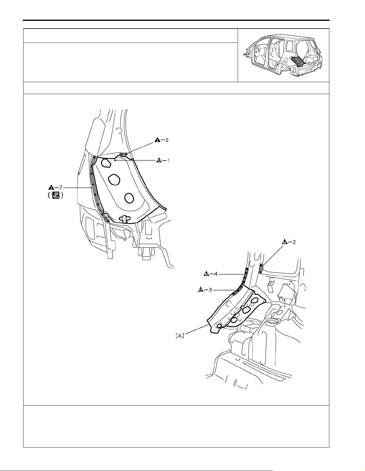
Page 27
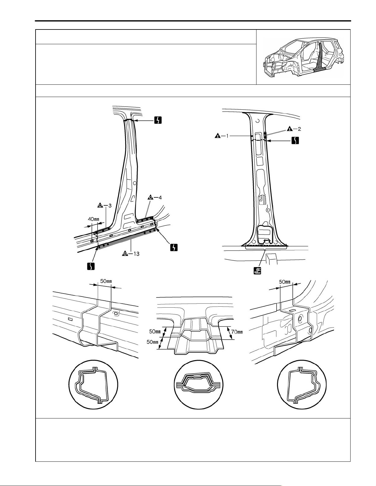
BODY PANEL REPLACEMENT
CENTER BODY PILLAR (CUT)
REPLACEMENT
REMOVAL
BP-27
F15527A
40mm (1.57in.) 50mm (1.97in.) 70mm (2.76in.)
F15527
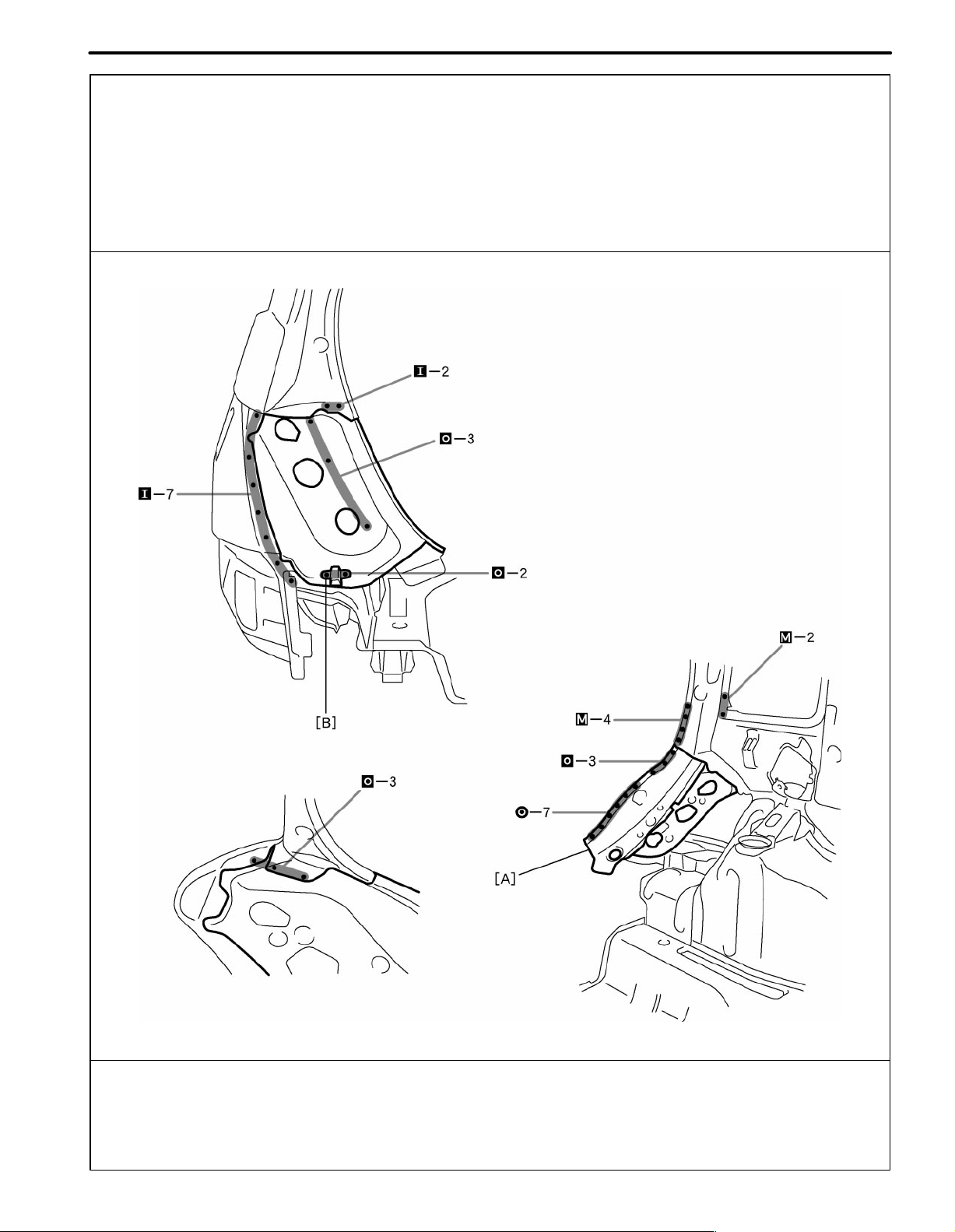
Page 28
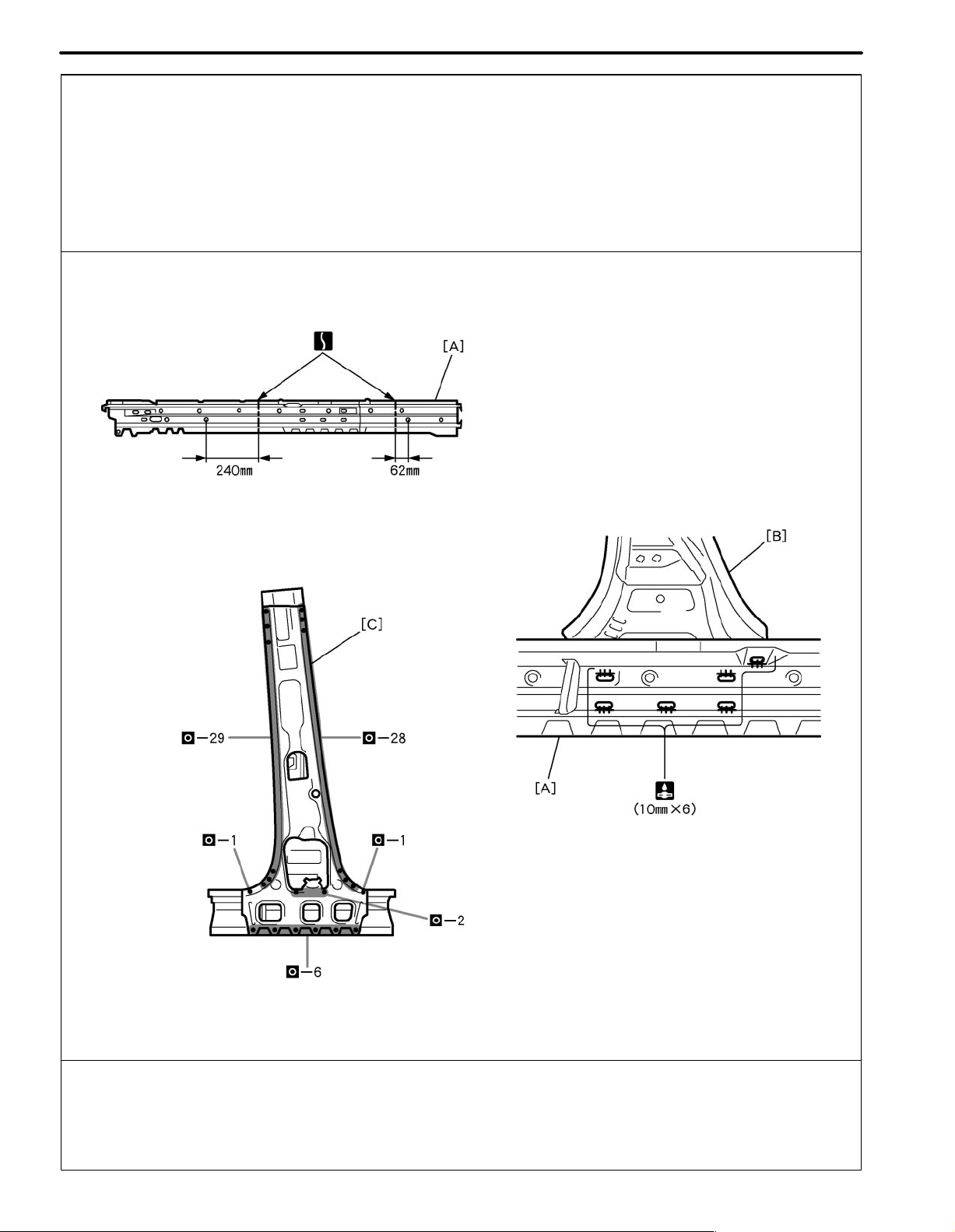
BP-28
BODY PANEL REPLACEMENT
INSTALLATION
Temporarily install the new parts and measure each part of the new parts in accordance with the body dimension
diagram. (See the body dimension diagram)
Inspect the fitting of the related parts around the new parts before welding. This affects the appearance of the
finish.
After welding, apply the polyurethane foam to the corresponding parts.
After welding, apply body sealer and under-coating to the corresponding parts.
After applying the top coat layer, apply anti-rust agent to the inside of the necked section structural weld spots.
POINT
1 Before temporarily installing the new parts, weld the [A], [B] and [C] with standard points.
PART NAME
[A] Rocker Outer Reinforcement
[B] Center Body Pillar Lower Reinforcement
[C] Center Body Inner Pillar
10mm (0.39in.) 62mm (2.44in.) 240mm (9.45in.)
F15528
Page 29
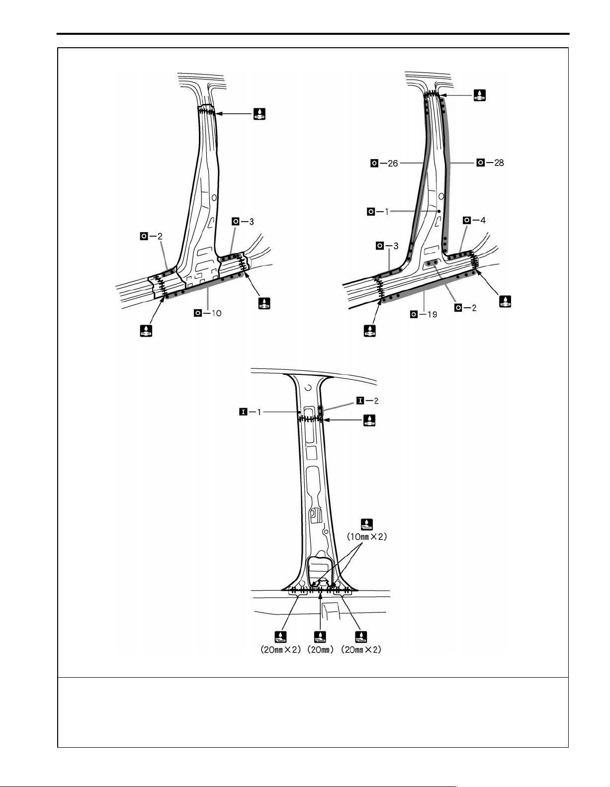
BODY PANEL REPLACEMENT
BP-29
F15529
POINT
1 Inspect the fitting of the front door and rear door, etc., before welding, since this affects the appearance of the
finish.
2 After welding the reinforcement to the vehicle side, install the outer panel.
10mm (0.39in.) 20mm (0.79in.)
Page 30
BODY PANEL REPLACEMENT
COWL TOP SIDE PANEL (ASSY)
REPLACEMENT
REMOVAL
BP-21
F15521A
F15521
Page 31

BP-22
BODY PANEL REPLACEMENT
INSTALLATION
Temporarily install the new parts and measure each part of the new parts in accordance with the body dimension
diagram. (See the body dimension diagram)
Inspect the fitting of the related parts around the new parts before welding. This affects the appearance of the
finish.
After welding, apply the polyurethane foam to the corresponding parts.
After welding, apply body sealer and under-coating to the corresponding parts.
After applying the top coat layer, apply anti-rust agent to the inside of the necked section structural weld spots.
25mm (0.98 in.) 30mm (1.18 in.)
F15522
Page 32

BODY PANEL REPLACEMENT
COWL TOP SIDE UPPER PANEL (ASSY)
REPLACEMENT
With the cowl top side panel removed.
REMOVAL
BP-11
F15511A
F15511
Page 33

BP-12
BODY PANEL REPLACEMENT
INSTALLATION
Temporarily install the new parts and measure each part of the new parts in accordance with the body dimension
diagram. (See the body dimension diagram)
Inspect the fitting of the related parts around the new parts before welding. This affects the appearance of the
finish.
After welding, apply the polyurethane foam to the corresponding parts.
After welding, apply body sealer and under-coating to the corresponding parts.
After applying the top coat layer, apply anti-rust agent to the inside of the necked section structural weld spots.
F15512
POINT
1 Inspect the fitting of the front fender and hood, etc. before welding, since this affects the appearance of the
finish.
20mm (0.79in.) 30mm (1.18in.)
Page 34

BODY PANEL REPLACEMENT
FRONT FENDER APRON (ASSY)
REPLACEMENT
With the radiator upper support and cowl top side panel removed.
REMOVAL
BP-15
F15515A
F15515
Page 35

BP-16
BODY PANEL REPLACEMENT
INSTALLATION
Temporarily install the new parts and measure each part of the new parts in accordance with the body dimension
diagram. (See the body dimension diagram)
Inspect the fitting of the related parts around the new parts before welding. This affects the appearance of the
finish.
After welding, apply the polyurethane foam to the corresponding parts.
After welding, apply body sealer and under-coating to the corresponding parts.
After applying the top coat layer, apply anti-rust agent to the inside of the necked section structural weld spots.
F15516
POINT
1 Inspect the fitting of the front fender and hood, etc. before welding, since this affects the appearance of the
finish.
2 Make sure each measurement is correct, as this parts affects the front wheel alignment.
PART NAME
[A] Front Fender Mounting Bracket
[B] Fender Apron Gusset
Page 36

BODY PANEL REPLACEMENT
FRONT SIDE MEMBER (ASSY)
REPLACEMENT
With the radiator side support and front fender apron removed.
REMOVAL
BP-19
F15519A
F15519
Page 37

BP-20
BODY PANEL REPLACEMENT
INSTALLATION
Temporarily install the new parts and measure each part of the new parts in accordance with the body dimension
diagram. (See the body dimension diagram)
Inspect the fitting of the related parts around the new parts before welding. This affects the appearance of the
finish.
After welding, apply the polyurethane foam to the corresponding parts.
After welding, apply body sealer and under-coating to the corresponding parts.
After applying the top coat layer, apply anti-rust agent to the inside of the necked section structural weld spots.
POINT
1 Make sure each measurement is correct, as this parts affects the front wheel alignment.
PART NAME
[A] Front Bumper Mounting Reinforcement (RH: Front Side Member Front Plate)
F15520
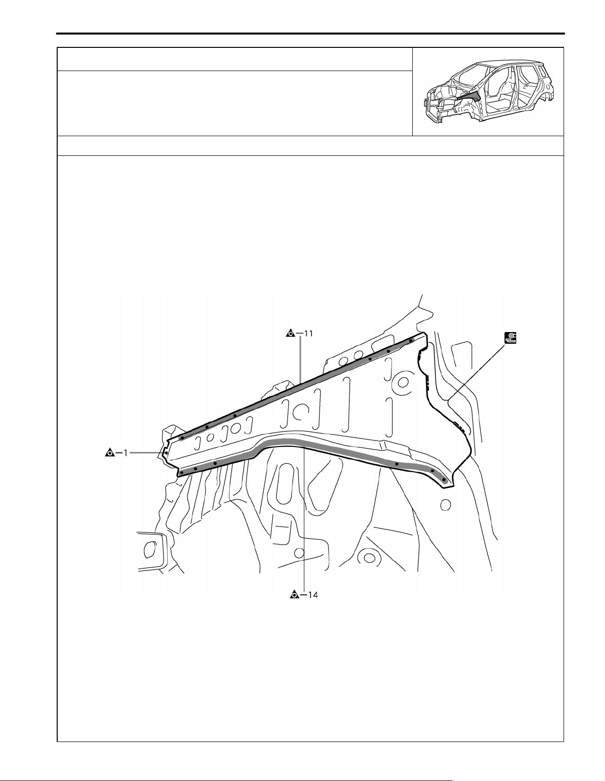
Page 38

BODY PANEL REPLACEMENT
FRONT APRON TO COWL SIDE UPPER
MEMBER (ASSY)
REPLACEMENT
With the front fender front apron and cowl top side panel removed.
REMOVAL
BP-13
F15513A
F15513
Page 39

BP-14
BODY PANEL REPLACEMENT
INSTALLATION
Temporarily install the new parts and measure each part of the new parts in accordance with the body dimension
diagram. (See the body dimension diagram)
Inspect the fitting of the related parts around the new parts before welding. This affects the appearance of the
finish.
After welding, apply the polyurethane foam to the corresponding parts.
After welding, apply body sealer and under-coating to the corresponding parts.
After applying the top coat layer, apply anti-rust agent to the inside of the necked section structural weld spots.
F15514
POINT
1 Inspect the fitting of the front fender and hood, etc. before welding, since this affects the appearance of the
finish.
PART NAME
[A] Fender Apron Gusset
Page 40

BODY PANEL REPLACEMENT
FRONT BODY PILLAR (CUT)
REPLACEMENT
With the cowl top side upper panel removed.
REMOVAL
BP-23
F15523A
30mm (1.18in.) 275mm (10.83in.)
F15523
Page 41

BP-24
BODY PANEL REPLACEMENT
F15524
Page 42

BODY PANEL REPLACEMENT
BP-25
INSTALLATION
Temporarily install the new parts and measure each part of the new parts in accordance with the body dimension
diagram. (See the body dimension diagram)
Inspect the fitting of the related parts around the new parts before welding. This affects the appearance of the
finish.
After welding, apply the polyurethane foam to the corresponding parts.
After welding, apply body sealer and under-coating to the corresponding parts.
After applying the top coat layer, apply anti-rust agent to the inside of the necked section structural weld spots.
F15525
POINT
1 Before temporarily installing the new parts, weld the [A], [B], [C] and [d] with standard points.
2 Cut the outer pillar on the rocker section and but-weld the rocker outer reinforcement before installing the outer
pillar.
PART NAME
[A] Rocker Outer Reinforcement
[C] Front Body Upper Outer Pillar
[B] Front Body Pillar Lower Reinforcement
[D] Front Body Inner Pillar
10mm (0.39in.) 15mm (0.59in.) 80mm (3.15in.) 100mm (3.94in.)
Page 43

BP-26
BODY PANEL REPLACEMENT
F15526
POINT
1 Inspect the fitting of the front door, front fender and windshield glass, etc., before welding, since this af fects the
appearance of the finish.
15mm (0.59in.) 20mm (0.79in.)
Page 44

BODY PANEL REPLACEMENT
FRONT FENDER FRONT APRON (ASSY)
REPLACEMENT
With the radiator upper support removed.
REMOVAL
BP-9
F15509A
F15509
Page 45

BP-10
BODY PANEL REPLACEMENT
INSTALLATION
Temporarily install the new parts and measure each part of the new parts in accordance with the body dimension
diagram. (See the body dimension diagram)
Inspect the fitting of the related parts around the new parts before welding. This affects the appearance of the
finish.
After welding, apply the polyurethane foam to the corresponding parts.
After welding, apply body sealer and under-coating to the corresponding parts.
After applying the top coat layer, apply anti-rust agent to the inside of the necked section structural weld spots.
F15510
POINT
1 Inspect the fitting of the front fender and hood, etc. before welding, since this affects the appearance of the
finish.
PART NAME
[A] Engine Front Support Retainer (RH Only)
[B] Front Fender Mounting Bracket
Page 46

BODY PANEL REPLACEMENT
FRONT SIDE MEMBER (CUT-P)
REPLACEMENT
With the radiator side support removed.
REMOVAL
BP-17
F15517A
PART NAME
[A] Front Bumper Mounting Reinforcement
200mm (7.87in.) 215mm (8.46in.)
F15517
[B] Front Side Member Front Plate
Page 47

BP-18
BODY PANEL REPLACEMENT
INSTALLATION
Temporarily install the new parts and measure each part of the new parts in accordance with the body dimension
diagram. (See the body dimension diagram)
Inspect the fitting of the related parts around the new parts before welding. This affects the appearance of the
finish.
After welding, apply the polyurethane foam to the corresponding parts.
After welding, apply body sealer and under-coating to the corresponding parts.
After applying the top coat layer, apply anti-rust agent to the inside of the necked section structural weld spots.
PART NAME
[A] Front Bumper Mounting Reinforcement
[C] Front Bumper Arm
F15518
[B] Front Side Member Front Plate
Page 48

BP-42
BODY PANEL REPLACEMENT
QUARTER WHEEL HOUSING EXTENSION
(ASSY)
REPLACEMENT
With the body lower back panel, quarter panel removed.
REMOVAL
F15542A
POINT
1 Remove the [A] and [B] at the same time.
PART NAME
[A] Quarter Wheel Housing Center Gusset
F15542
[B] Quarter Wheel Housing No.2 Brace
Page 49

BODY PANEL REPLACEMENT
BP-43
INSTALLATION
Temporarily install the new parts and measure each part of the new parts in accordance with the body dimension
diagram. (See the body dimension diagram)
Inspect the fitting of the related parts around the new parts before welding. This affects the appearance of the
finish.
After welding, apply the polyurethane foam to the corresponding parts.
After welding, apply body sealer and under-coating to the corresponding parts.
After applying the top coat layer, apply anti-rust agent to the inside of the necked section structural weld spots.
PART NAME
[A] Quarter Wheel Housing Center Gusset
F15543
[B] Quarter Wheel Housing No.2 Brace
Page 50

BP-44
BODY PANEL REPLACEMENT
QUARTER PANEL UPPER EXTENSION (CUT)
REPLACEMENT
With the quarter panel, back door opening trough removed.
REMOVAL
F15544A
80mm (3.15in.)
F15544
Page 51

BODY PANEL REPLACEMENT
BP-45
INSTALLATION
Temporarily install the new parts and measure each part of the new parts in accordance with the body dimension
diagram. (See the body dimension diagram)
Inspect the fitting of the related parts around the new parts before welding. This affects the appearance of the
finish.
After welding, apply the polyurethane foam to the corresponding parts.
After welding, apply body sealer and under-coating to the corresponding parts.
After applying the top coat layer, apply anti-rust agent to the inside of the necked section structural weld spots.
F15545
Page 52

BP-34
QUARTER PANEL (CUT)
REPLACEMENT
REMOVAL
BODY PANEL REPLACEMENT
F15534A
200mm (7.87in.) 220mm (8.66in.)
F15534
Page 53

BODY PANEL REPLACEMENT
BP-35
INSTALLATION
Temporarily install the new parts and measure each part of the new parts in accordance with the body dimension
diagram. (See the body dimension diagram)
Inspect the fitting of the related parts around the new parts before welding. This affects the appearance of the
finish.
After welding, apply the polyurethane foam to the corresponding parts.
After welding, apply body sealer and under-coating to the corresponding parts.
After applying the top coat layer, apply anti-rust agent to the inside of the necked section structural weld spots.
F15535
POINT
1 Before temporarily installing the new parts, apply sealer to wheel arch.
HINT:
1) Apply body sealer about 5mm (0.20in.) from the flange, avoiding any oozing.
2) Apply sealer evenly, about 3 - 4mm (0.12 - 0.16in.) in diameter.
2 Inspect the fitting of the rear door, back door and rear combination light, etc., before welding, since this affects
the appearance of the finish.
PART NAME
[A] Fuel Filler Opening Lid
[B] Waterproof Rivets
Page 54

BP-36
BODY PANEL REPLACEMENT
QUARTER WHEEL HOUSING OUTER PANEL
(ASSY)
REPLACEMENT
With the quarter panel removed.
REMOVAL
F15536A
POINT
1 After removing [A], remove the quarter wheel housing outer panel.
PART NAME
[A] Roof Side Outer Panel
80mm (3.15 in.)
F15536
Page 55

BODY PANEL REPLACEMENT
BP-37
INSTALLATION
Temporarily install the new parts and measure each part of the new parts in accordance with the body dimension
diagram. (See the body dimension diagram)
Inspect the fitting of the related parts around the new parts before welding. This affects the appearance of the
finish.
After welding, apply the polyurethane foam to the corresponding parts.
After welding, apply body sealer and under-coating to the corresponding parts.
After applying the top coat layer, apply anti-rust agent to the inside of the necked section structural weld spots.
POINT
1 Determine the position of the new parts by assembly marks of the inner and outer panels.
PART NAME
[A] Roof side Outer Panel
F15537
Page 56

BODY PANEL REPLACEMENT
RADIATOR SIDE SUPPORT (ASSY)
REPLACEMENT
With the radiator upper support removed.
REMOVAL
BP-3
F15503A
F15503
Page 57

BP-4
BODY PANEL REPLACEMENT
INSTALLATION
Temporarily install the new parts and measure each part of the new parts in accordance with the body dimension
diagram. (See the body dimension diagram)
Inspect the fitting of the related parts around the new parts before welding. This affects the appearance of the
finish.
After welding, apply the polyurethane foam to the corresponding parts.
After welding, apply body sealer and under-coating to the corresponding parts.
After applying the top coat layer, apply anti-rust agent to the inside of the necked section structural weld spots.
PART NAME
[A] Front Bumper Side Mounting Bracket
F15504
[B] Radiator Support Reinforcement
Page 58

BODY PANEL REPLACEMENT
RADIATOR LOWER SUPPORT (ASSY)
REPLACEMENT
REMOVAL
BP-5
F15505A
F15505
Page 59

BP-6
BODY PANEL REPLACEMENT
INSTALLATION
Temporarily install the new parts and measure each part of the new parts in accordance with the body dimension
diagram. (See the body dimension diagram)
Inspect the fitting of the related parts around the new parts before welding. This affects the appearance of the
finish.
After welding, apply the polyurethane foam to the corresponding parts.
After welding, apply body sealer and under-coating to the corresponding parts.
After applying the top coat layer, apply anti-rust agent to the inside of the necked section structural weld spots.
F15506
Page 60

BODY PANEL REPLACEMENT
RADIATOR SUPPORT (ASSY)
REPLACEMENT
REMOVAL
BP-7
F15507A
F15507
Page 61

BP-8
BODY PANEL REPLACEMENT
INSTALLATION
Temporarily install the new parts and measure each part of the new parts in accordance with the body dimension
diagram. (See the body dimension diagram)
Inspect the fitting of the related parts around the new parts before welding. This affects the appearance of the
finish.
After welding, apply the polyurethane foam to the corresponding parts.
After welding, apply body sealer and under-coating to the corresponding parts.
After applying the top coat layer, apply anti-rust agent to the inside of the necked section structural weld spots.
F15508
Page 62

BODY PANEL REPLACEMENT
RADIATOR UPPER SUPPORT (ASSY)
REPLACEMENT
REMOVAL
BP-1
F15501A
F15501
Page 63

BP-2
BODY PANEL REPLACEMENT
INSTALLATION
Temporarily install the new parts and measure each part of the new parts in accordance with the body dimension
diagram. (See the body dimension diagram)
Inspect the fitting of the related parts around the new parts before welding. This affects the appearance of the
finish.
After welding, apply the polyurethane foam to the corresponding parts.
After welding, apply body sealer and under-coating to the corresponding parts.
After applying the top coat layer, apply anti-rust agent to the inside of the necked section structural weld spots.
PART NAME
[A] Apron Fender Side Extension [B] Cool Air Intake Duct Mounting Bracket (LH Only)
F15502
Page 64

BP-48
BODY PANEL REPLACEMENT
REAR FLOOR PAN EXTENSION (ASSY)
REPLACEMENT
With the body lower back panel removed.
REMOVAL
F15548A
F15548
Page 65

BODY PANEL REPLACEMENT
BP-49
INSTALLATION
Temporarily install the new parts and measure each part of the new parts in accordance with the body dimension
diagram. (See the body dimension diagram)
Inspect the fitting of the related parts around the new parts before welding. This affects the appearance of the
finish.
After welding, apply the polyurethane foam to the corresponding parts.
After welding, apply body sealer and under-coating to the corresponding parts.
After applying the top coat layer, apply anti-rust agent to the inside of the necked section structural weld spots.
F15549
Page 66

BP-50
BODY PANEL REPLACEMENT
REAR FLOOR SIDE REAR MEMBER (ASSY)
REPLACEMENT
With the body lower back panel removed.
REMOVAL
F15550A
F15550
Page 67

BODY PANEL REPLACEMENT
BP-51
INSTALLATION
Temporarily install the new parts and measure each part of the new parts in accordance with the body dimension
diagram. (See the body dimension diagram)
Inspect the fitting of the related parts around the new parts before welding. This affects the appearance of the
finish.
After welding, apply the polyurethane foam to the corresponding parts.
After welding, apply body sealer and under-coating to the corresponding parts.
After applying the top coat layer, apply anti-rust agent to the inside of the necked section structural weld spots.
F15551
Page 68

BP-52
BODY PANEL REPLACEMENT
REAR FLOOR NO.2 CROSSMEMBER (ASSY)
REPLACEMENT
REMOVAL
F15553A
F15553
Page 69

BODY PANEL REPLACEMENT
BP-53
INSTALLATION
Temporarily install the new parts and measure each part of the new parts in accordance with the body dimension
diagram. (See the body dimension diagram)
Inspect the fitting of the related parts around the new parts before welding. This affects the appearance of the
finish.
After welding, apply the polyurethane foam to the corresponding parts.
After welding, apply body sealer and under-coating to the corresponding parts.
After applying the top coat layer, apply anti-rust agent to the inside of the necked section structural weld spots.
F15554
Page 70

BP-46
REAR FLOOR PAN (ASSY)
REPLACEMENT
With the body lower back panel removed.
REMOVAL
BODY PANEL REPLACEMENT
F15546A
F15546
Page 71

BODY PANEL REPLACEMENT
BP-47
INSTALLATION
Temporarily install the new parts and measure each part of the new parts in accordance with the body dimension
diagram. (See the body dimension diagram)
Inspect the fitting of the related parts around the new parts before welding. This affects the appearance of the
finish.
After welding, apply the polyurethane foam to the corresponding parts.
After welding, apply body sealer and under-coating to the corresponding parts.
After applying the top coat layer, apply anti-rust agent to the inside of the necked section structural weld spots.
PART NAME
[A] Floor Clamp Bracket
[D] Jack Up Bracket
F15547
[B] Fuel Tube Bracket [C] Rear Floor Heat Insulator No.3 Bracket
[E] Spare Wheel Clamp Bracket
Page 72

BP-32
BODY PANEL REPLACEMENT
ROCKER OUTER PANEL (CUT)
REPLACEMENT
REMOVAL
F15532A
80mm (31.5in.)
F15532
Page 73

BODY PANEL REPLACEMENT
BP-33
INSTALLATION
Temporarily install the new parts and measure each part of the new parts in accordance with the body dimension
diagram. (See the body dimension diagram)
Inspect the fitting of the related parts around the new parts before welding. This affects the appearance of the
finish.
After welding, apply the polyurethane foam to the corresponding parts.
After welding, apply body sealer and under-coating to the corresponding parts.
After applying the top coat layer, apply anti-rust agent to the inside of the necked section structural weld spots.
F15533
POINT
1 Inspect the fitting the front door and rear door, etc., before welding, since this affects the appearance of the
finish.
Page 74

BP-30
BODY PANEL REPLACEMENT
ROCKER OUTER PANEL (CUT-P)
REPLACEMENT
REMOVAL
F15530A
350mm (13.78in.)
F15530
Page 75

BODY PANEL REPLACEMENT
BP-31
INSTALLATION
Temporarily install the new parts and measure each part of the new parts in accordance with the body dimension
diagram. (See the body dimension diagram)
Inspect the fitting of the related parts around the new parts before welding. This affects the appearance of the
finish.
After welding, apply the polyurethane foam to the corresponding parts.
After welding, apply body sealer and under-coating to the corresponding parts.
After applying the top coat layer, apply anti-rust agent to the inside of the necked section structural weld spots.
POINT
1 Inspect the fitting of the front door, etc., before welding, since this affects the appearance of the finish.
F15531
Page 76

BP-56
BODY PANEL REPLACEMENT
ROOF PANEL (ASSY): w/ sun roof
REPLACEMENT
REMOVAL
F15557A
POINT
1 If reusing the roof panel reinforcement, trim the hemming location using a disc sander, etc.
F15557
Page 77

BODY PANEL REPLACEMENT
BP-57
INSTALLATION
Temporarily install the new parts and measure each part of the new parts in accordance with the body dimension
diagram. (See the body dimension diagram)
Inspect the fitting of the related parts around the new parts before welding. This affects the appearance of the
finish.
After welding, apply the polyurethane foam to the corresponding parts.
After welding, apply body sealer and under-coating to the corresponding parts.
After applying the top coat layer, apply anti-rust agent to the inside of the necked section structural weld spots.
F15558
POINT
1 Before temporarily installing the new parts, apply body sealer to the windshield header panel, roof panel rein-
forcement and back window frame.
HINT:
1) Apply just enough sealer for the new parts to make contact.
2 Bend the flange hem with a wooden hammer and dolly.
HINT:
1) Perform hemming three steps, being careful not to warp the panel.
Page 78

BP-54
BODY PANEL REPLACEMENT
ROOF PANEL (ASSY): w/o sun roof
REPLACEMENT
REMOVAL
F15555A
F15555
Page 79

BODY PANEL REPLACEMENT
BP-55
INSTALLATION
Temporarily install the new parts and measure each part of the new parts in accordance with the body dimension
diagram. (See the body dimension diagram)
Inspect the fitting of the related parts around the new parts before welding. This affects the appearance of the
finish.
After welding, apply the polyurethane foam to the corresponding parts.
After welding, apply body sealer and under-coating to the corresponding parts.
After applying the top coat layer, apply anti-rust agent to the inside of the necked section structural weld spots.
F15556
POINT
1 Before temporarily installing the new parts, apply body sealer to the windshield header panel reinforcement
and back window frame.
HINT:
1) Apply just enough sealer for the new parts to make contact.
Page 80

PC-6
PAINT COATING
BODY PANEL UNDERCOATING AREAS
HINT:
1) First wipe off any dirt, grease or oil with a rag soaked in a grease, wax and silicone remover.
2) Cover the surrounding areas with masking paper to avoid coating unnecessary areas. If other areas are accidently coated, wipe off the coating immediately.
3) Apply the first coating of undercoat to all welded areas and panel joints, then apply a second coat over the
entire area.
4) Do not coat parts which become hot, such as the tailpipe, or moving parts, such as the propeller shaft.
5) Besides the locations described below, apply undercoating to all weld points under the body to insure corrosion prevention.
6) Be sure to seal the edge of the flange of the member and bracket with undercoating.
7) If undercoat is damaged by peeling, cracks, etc., be sure to repair as necessary.
8) Before the undercoat apply sealer allowing rust prevention to be attained.
REFERENCE
Referring to the notes above, undercoating should be applied according to the specifications for your country.
F15564
Page 81

PC-8
PAINT COATING
BODY PANEL ANTI-RUST AGENT (WAX) APPLICATION AREAS
HINT:
1) Whenever adjusting the doors and hoods, apply anti-rust agent (wax) around the hinges.
2) Even if partially repairing a part, apply anti-rust agent (wax) over the entire application area of the part.
3) Wipe off the anti-rust agent immediately with a rag soaked in a grease, wax and silicone remover, if accidently
applied to other areas.
F15565
Page 82

PC-10
PAINT COATING
BODY PANEL ANTI-CHIPPING PAINT APPLICATION AREAS
HINT:
1) Anti-chipping paint should be applide to some areas before the second coat and to others after the top coat.
2) If other areas are accidentally coated, wipe of the paint immediately with a rag soaked in grease, wax and
silicone remover.
PVC Urethane
F15568
Page 83

PAINT COATING
PC-1
BODY PANEL SEALING AREAS
HINT:
1) Prior to applying body sealer, clean the area with a rag soaked in grease,wax and silicone remover.
2) If weld-through primer was used, first wipe off any excess and coat with anti-corrosion primer before applying
body sealer.
3) Wipe off excess body sealer with a rag soaked in a grease, wax and silicone remover.
4) If body sealer is damaged by peeling, cracks, etc., be sure to repair as necessary.
Flat Finishing No Flat Finishing
1. ENGINE COMPARTMENT
F15559
Page 84

PC-2
2. INSIDE
PAINT COATING
F15560
Page 85

3. REAR LUGGAGE COMPARTMENT
PAINT COATING
PC-3
F15561
Page 86

PC-4
4. DOOR PARTS
PAINT COATING
F15562
Page 87

PAINT COATING
PC-5
F15563
Page 88

PAINT COATING
FOAMED MATERIAL APPLICATION AREAS
The sections shown in the figure below are filled with foamed material to provide noise insullation.
After repairing these sections or their peripheries, refill with foamed materials
HINT:
1) Use the service holes located on the reverse side of the body panel to refill with foamed materials.
2) When handling foamed material, follow the directions of the material’s manufacturer.
PC-7
F15566
Page 89

PAINT COATING
SILENCER SHEET INSTALLATION AREAS
PC-9
non-adhesive sheet
F15567
Page 90

BODY DIMENSIONS
BODY DIMENSION DRAWINGS
ENGINE COMPARTMENT
(Three-Dimensional Distance)
C
332
A
(13.07)
1,330
(52.36)
1,352
(53.23)
DI-3
c
N
B
697
(27.44)
M
720
(28.35)
L
1,254
(49.37)
G
K
1,292
(50.87)
F
1,194
(47.01)
995
(39.17)
(31.26)
794
545
(21.46)
D
1,040
(40.94)
1,001
(39.41)
556
(21.89)
l
1,262
(49.69)
206
n
(8.11)
b
a
m
g
804
(31.65)
884
(34.80)
988
(38.90)
548
(21.57)
e
k
j
h
E
J
594
(23.39)
H
408
(16.06)
I
Vehicle Dimensions Left Right
B-D
or D-E D-e K-k L-l N-n
b-D
523 765 768 1,544 792 1,305
(20.59) (30.12) (30.24) (60.79) (31.18) (51.38)
HINT: For symbols, capital letters indicate right side of vehicle,
small letters indicate left side of vehicle (Seen from rear).
mm (in.)
Symbol Name Hole dia. Symbol Name Hole dia.
A, a
B, b
C, c
D
E, e
F
G, g
Radiator upper support standard hole
Front spring support hole-inner
Hood hinge installation nut
Cowl top outer panel installation nut
Air bag sensor installation nut
Brake tube installation nut
f
ABS actuator installation nut
Radiator upper center support installation nut
12 (0.47)
11 (0.43)
8 (0.31) nut
6 (0.24) nut
8 (0.31) nut
6 (0.24) nut
8 (0.31) nut
6 (0.24) nut
H, h
I
J, j
K, k
L, l
M, m
N, n
—
Radiator support standard hole
Hood lock support installation nut
Front bumper reinforcement installation bolt
Front fender mounting bracket standard hole
Radiator upper center support installation nut
Front fender installation nut
Front fender installation nut
—
10x8(0.39x0.31)
6 (0.24) nut
8 (0.31) bolt
10 (0.39)
6 (0.24) nut
6 (0.24) nut
6 (0.24) nut
—
Page 91

BODY DIMENSIONS
BODY OPENING AREAS (Side View: Rear)
(Three-Dimensional Distance)
DI-5
HINT: For symbols, capital letters indicate right side of vehicle,
small letters indicate left side of vehicle (Seen from rear).
Vehicle Dimensions Left Right
o
n
851
(33.50)
939
(36.97)
522
(20.55)
q
1,084
(42.68)
677
(26.65)
1,052
(41.42)
i
r
s
p
g
N-n O-o P-p Q-q R-r S-s
1,273 1,362 1,365 1,069 1,189 1,363
(50.12) (53.62) (53.74) (42.09) (46.81) (53.66)
G-p I-q N-r N-s O-s P-q R-s
or or or or or or or
g-P i-Q n-R n-S o-S p-Q r-S
1,632 1,284 1,404 1,568 1,459 1,623 1,506
(64.25) (50.55) (55.28) (61.73) (57.44) (63.90) (59.29)
mm (in.)
Symbol Name Hole dia. Symbol Name Hole dia.
G, g
I,i
N, n
O, o
Rocker panel assembly mark
Roof side rail assembly mark
Center body pillar assembly mark
Center body pillar assembly mark
—
—
—
—
P, p
Q, q
R, r
S, s
Rocker panel assembly mark
Roof side rail assembly mark
Quarter panel assembly mark
Quarter panel assembly mark
—
—
—
—
Page 92

DI-6
BODY DIMENSIONS
BODY OPENING AREAS (Rear View)
(Three-Dimensional Distance)
945
(37.20)
A
(29.41)
B
747
a
h
b
1,557
(61.30)
985
(38.78)
C
1,112
c
d
g
e
507
(19.96)
(43.78)
1,069
(42.09)
1,426
(56.14)
985
(38.78)
948
(37.32)
G
F
D
E
f
G-H
or
g-h
1,031
(40.59)
HINT: For symbols, capital letters indicate right side of vehicle,
small letters indicate left side of vehicle (Seen from rear).
mm (in.)
Symbol Name Hole dia. Symbol Name Hole dia.
A, a
B, b
C, c
D, d
Back door hinge installation hole
Back door damper stay installation nut
Roof side inner garnish installation bole
Quarter panel standard hole
RH: 10.2
(0.402)
LH: 13x10.2
(0.51x0.402)
6 (0.24) nut
8.5 (0.335)
10 (0.39)
E, e
F, f
G, g
H, h
—
Deck trim side panel installation hole
Deck trim rear cover installation hole
Rear shock absorber installation hole
Center body pillar assembly mark
—
8.5 (0.335)
7 (0.28)
18 (0.71)
—
—
Page 93

DI-4
BODY DIMENSIONS
BODY OPENING AREAS (Side View: Front)
(Three-Dimensional Distance)
A
1,039
(40.91)
802
(31.57)
B
1,216
(47.87)
1,381
(54.37)
e
b
c
914
(35.98)
1,063
(41.85)
a
816
(32.13)
872
(34.33)
i
1,078
(42,44)
1,171
(46.10)
j
l
k
f
836
(32.91)
1,002
(39.45)
m
d
h
g
HINT: For symbols, capital letters indicate right side of vehicle,
small letters indicate left side of vehicle (Seen from rear).
Vehicle Dimensions Left Right
E-e F-f G-g H-h I-i J-j K-k
1,265 1,366 1,365 1,365 1,084 1,265 1,362
(49.80) (53.78) (53.74) (53.74) (42.68) (49.80) (53.62)
E-f E-h E-j F-j F-k H-i J-k
or or or or or or or
e-F e-H e-J f-J f-K h-I j-K
1,482 1,601 1,505 1,760 1,600 1,625 1,427
(58.35) (63.03) (59.25) (69.29) (62.99) (63.98) (56.18)
mm (in.)
Symbol Name Hole dia. Symbol Name Hole dia.
A, a
B, b
C, c
D, d
E, e
F, f
G, g
Roof panel corner
Cowl top outer panel/Front body pillar adjoining portion
Front door hinge installation nut
Front door hinge installation nut
Front body pillar assembly mark
Front body pillar assembly mark
Rocker panel assembly mark
—
—
8 (0.31) nut
8 (0.31) nut
—
—
—
H, h
I,i
J, j
K, k
L, l
M, m
—
Rocker panel assembly mark
Roof side rail assembly mark
Center body pillar assembly mark
Center body pillar assembly mark
Rear door hinge installation nut
Rear door hinge installation nut
—
—
—
—
—
8 (0.31) nut
8 (0.31) nut
—
Page 94

BODY DIMENSIONS
DI-1
Three-dimensional
distance
Two-dimensional
distance
Vertical distance
in center
Imaginary Standard Line
Center-to-center
straight-line
distance
Center-to-center
Horizontal distance
in forward/rearward
Vertical distance
in lower surface
Under Surface of
The Rocker Panel
GENERAL INFORMATION
1. BASIC DIMENSIONS
(a) There are two types of dimensions in the diagram.
(1) (Three-dimensional distance)
Straight-line distance between the centers of two
measuring points.
(2) (Two-dimensional distance)
Horizontal distance in forward/rearward between the
centers of two measuring points.
The height from an imaginary standard line.
(b) In cases in which only one dimension is given, left and right
are symmetrical.
(c) The dimensions in the following drawing indicate actual dis-
tance. Therefore, please use the dimensions as a reference.
(d) The line that connects the places listed below is the imagi-
nary standard line when measuring the height. (The dimensions are printed in the text.)
Imaginary Standard Line
SYMBOL Name
1
2
3
The place that was lowered A mm from the under surface of
the rocker panel centered on the front jack up point.
The place that was lowered B mm from the under surface of
the rocker panel centered between 1 and 3.
The place that was lowered C mm from the under surface of
the rocker panel centered on the rear jack up point.
Page 95

DI-2
BODY DIMENSIONS
Plate Looseness
Body Looseness
Pointer Looseness
Pointer
Master Gauge
Wrong Correct
Pointer
2. MEASURING
(a) Basically , all measurements are to be done with a tracking
gauge. For portions where it is not possible to use a tracking gauge, a tape measure should be used.
(b) Use only a tracking gauge that has no looseness in the
body, measuring plate, or pointers.
HINT:
1) The height of the left and right pointers must be equal.
2) Always calibrate the tracking gauge before measuring
or after adjusting the pointer height.
3) Take care not to drop the tracking gauge or otherwise
shock it.
4) Confirm that the pointers are securely in the holes.
(c) When using a tape measure, avoid twists and bends in the
tape.
Page 96

UNDER BODY
(Three-Dimensional Distance)
BODY DIMENSIONS
DI-7
RH
LH
Front
(17.32)
988
(38.90)
440
930
(36.61)
489
(19.25)
1,095
(43.11)
(40.59)
(34.84)
1,164
(45.83)
1,031
885
(33.78)
922
(36.30)
300
(11.81)
858
895
(35.24)
256
(10.08)
856
(33.70)
973
(38.31)
1,117
(43.98)
(18.23)
463
452
(17.80)
856
(33.70)
968
(38.11)
1,252
(49.29)
(33.70)
123
100 100 100
(3.94) (3.94) (3.94)
856
374
(14.72)
1,080
(42.52)
1,200
(47.24)
1,066
(41.97)
697
(27.44)
1,451
(57.13)
1,269
(49.96)
936
(36.85)
304
(11.97)
(36.85)
984
(38.74)
936
A,a
388
(15.28)
B,b
154
(6.06)
C,c
310
(12.20)
D,d
295
(11.61)
E,e
100
(3.94)
F,f
57
(2.24)
G,g
57
(2.24)
H,h
58
(2.28)
I,i
137
(5.39)
J,j
147
(5.79)
K,k
287
(11.30)
L,l
283
(11.14)
Imaginary
Standard
Line
mm (in.)
Symbol Name Hole dia. Symbol Name Hole dia.
A, a
B, b
C, c
D, d
E, e
Front bumper reinforcement installation bolt
Radiator lower support standard hole
Front side member standard hole
Front suspension member installation nut
Front suspension member installation nut
F, f
Front side member standard hole
8 (0.31) bolt
15 (0.59)
18 (0.71)
12 (0.47) nut
14 (0.55) nut
18 (0.71)
G, g
H, h
I,i
J, j
K, k
L, l
Front side member standard hole
Front floor under reinforcement standard hole
Rear floor side member standard hole
Trailing arm installation hole-inner
Rear floor side member standard hole
Transport hook installation nut
18 (0.71)
18 (0.71)
18 (0.71)
13 (0.51)
18 (0.71)
10 (0.39) nut
Page 97

DI-8
UNDER BODY (Cont’d)
(Two-Dimensional Distance)
BODY DIMENSIONS
RH
LH
2,069
(81.46)
Front
1,985
(78.15)
(8.66)
494
(19.45)
220
(18.31)
1,882
(74.09)
465
1,394
1,167
(54.88)
443
(17.44)
611
(24.06)
1,393
(54.84)
(45.94)
429
(16.89)
428
(16.85)
915
(36.02)
(17.80)
(16.85)
Wheel base 2,370 (93.31)
452
428
0
520
(20.47)
I
600
(23.62)
322
(12.68)
533
(20.98)
428
(16.85)
428
(16.85)
0
123
100 100 100
(3.94) (3.94) (3.94)
990
(38.98)
468
(18.43)
535
(21.06)
983
(38.70)
468
(18.43)
1,294
(50.94)
A,a
388
(15.28)
B,b
154
(6.06)
C,c
310
(12.20)
D,d
295
(11.61)
E,e
752
(29.61)
F,f
100
(3.94)
G,g
57
(2.24)
H,h
57
(2.24)
I,i
58
(2.28)
J,j
137
(5.39)
K,k
147
(5.79)
L,l
659
(25.94)
M.m
287
(11.30)
N,n
283
(11.14)
Imaginary
Standard
Line
mm (in.)
Symbol Name Hole dia. Symbol Name Hole dia.
A, a
B, b
C, c
D, d
E, e
G, g
Front bumper reinforcement installation bolt
Radiator lower support standard hole
Front side member standard hole
Front suspension member installation nut
Front spring support hole-outer
F, f
Front suspension member installation nut
Front side member standard hole
8 (0.31) bolt
15 (0.59)
18 (0.71)
12 (0.47) nut
11 (0.43)
14 (0.55) nut
18 (0.71)
H, h
I,i
J, j
K, k
L, l
M, m
N, n
Front side member standard hole
Front floor under reinforcement standard hole
Rear floor side member standard hole
Trailing arm installation hole-inner
Rear shock absorber installation hole
Rear floor side member standard hole
Transport hook installation nut
18 (0.71)
18 (0.71)
18 (0.71)
13 (0.51)
18 (0.71)
18 (0.71)
10 (0.39) nut
 Loading...