

TOYOTA LAND CRUISER 2010 - TVIP V4
Preparation REMOTE ENGINE STARTER (RES)
Part Number: PT398-60080
or PT398-60101
Conflicts
Do not install into vehicles without RKE systems.
Recommended Sequence of Application
Item # Accessory
1 XM XM Radio
2 TVIP V2 Glass Breakage Sensor (GBS)
and/or
V4 Remote Engine Starter (RES)
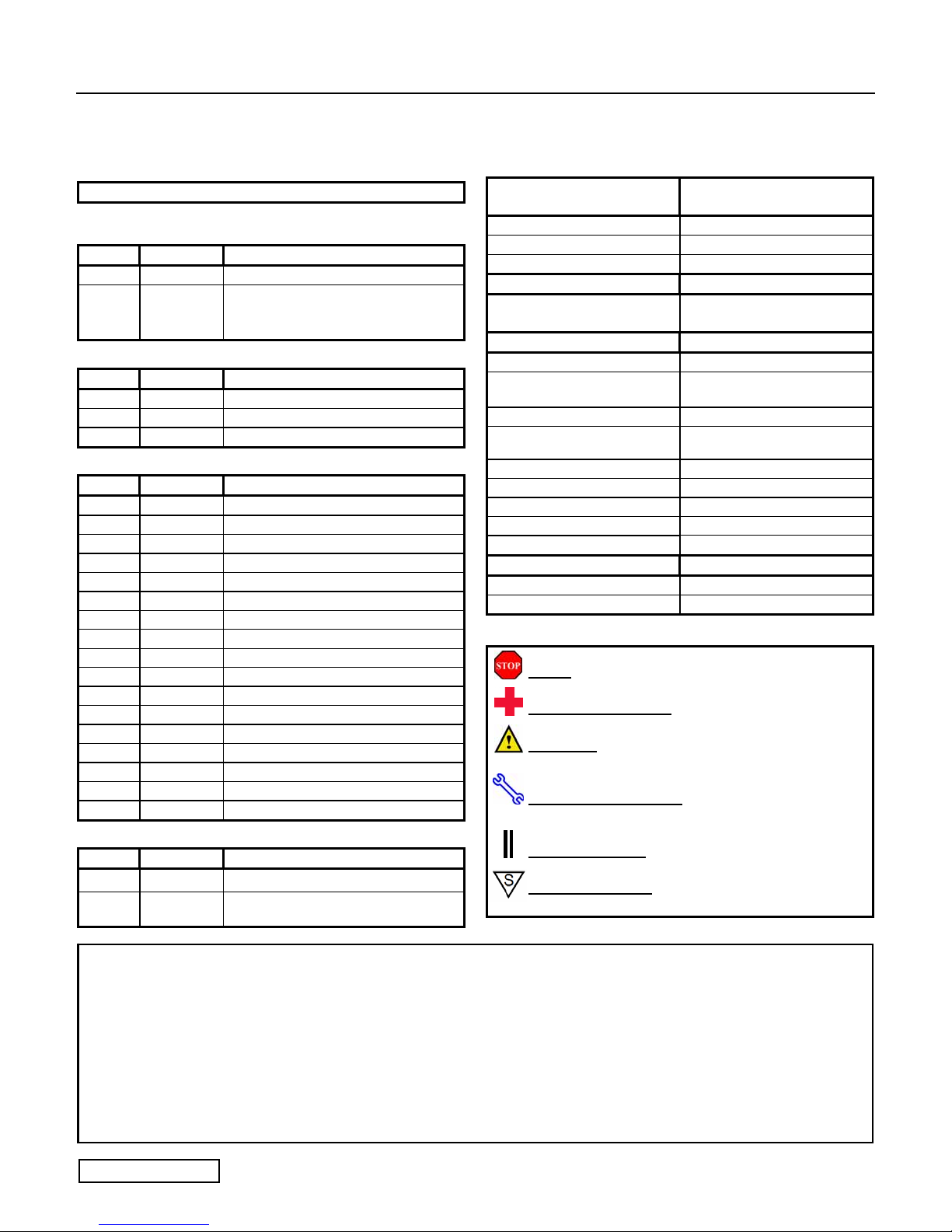
Kit Contents
Item # Quantity Description
1 1 Wire Harness
2 1 RES ECU Bracket
3 1 Extra Large Wire Tie
Hardware Bag Contents
Item # Quantity Description
1 1 RES ECU
2 1 Gateway ECU
3 1 Gateway ECU Bracket
4 1 M6 Tapping Screw
5 15 Wire Ties
6 1 Waterproof Sheet
7 2 Large Foam Tape (1sheet 2pcs)
8 1 Custom Double Stick Tape
9 2 Key Tag (English)
10 2 Window Labels (English)
11 2 Transmitter Labels (English)
12 1
13 2 Key Tag (Spanish)
14 2 Window Labels (Spanish)
15 2 Transmitter Labels (Spanish)
16 1
17 1 Owner’s Guide
Additional Items Required For Installation
Item #
1 1 Black Electrical Tape
2 1
Quantity Description
Engine Room Warning Label (English)
Engine Room Warning Label (Spanish)
Harness Kit PT398-60090-RS for
LC Kit PT398-60080 ONLY see pg. 2
NOTE: Part number of this accessory may not be the same
as the part number shown.
Recommended Tools
Personal & Vehicle
Protection
Safety Glasses
Safety Gloves (Optional)
Vehicle Protection Blankets, Parts Boxes
Special Tools Notes
Techstream
Installation Tools Notes
Screwdriver
Nylon Panel Removal Tool
Side Cutters
Torque Wrench
Utility Knife
Pliers Clip Clamp Pliers
Tape Clear
Wrench 10mm
Socket
Special Chemicals Notes
Cleaner VDC Approved Cleaner
Glass Cleaner Household Glass Cleaner
Notes
Software version 4.00.017 or
later
#2 Phillips, Flat Blade Jeweler’s
e.g. Panel Pry Tool #1
Toyota SST # 00002-06001-01
36 in•lbf (4.07 N•m)
88.5 in•lbf (10 N•m)
10mm, Extension, 10mm Deep
Legend
STOP: Damage to the vehicle may occur. Do not
proceed until process has been complied with.
OPERATOR SAFETY:
injury.
CAUTION:
in order to reduce the risk of damage to the
accessory/vehicle and to ensure a quality installation.
TOOLS & EQUIPMENT:
specific tools and equipment recommended for this
process.
REVISION MARK:
installation with respect to previous issue.
SAFETY TORQUE:
related to safety.
A process that must be carefully observed
Use caution to avoid risk of
Used in Figures calls out the
This mark highlights a change in
This mark indicates that torque is
Care must be taken when installing this accessory to ensure damage does not occur to the vehicle. The installation of this
accessory should follow approved guidelines to ensure a quality installation.
These guidelines can be found in the "Accessory Installation Practices" document.
This document covers such items as:
• Vehicle Protection (use of covers and blankets, cleaning chemicals, etc.)
• Safety (eye protection, rechecking torque procedure, etc.)
• Vehicle Disassembly/Reassembly (panel removal, part storage, etc.)
• Electrical Component Disassembly/Reassembly (battery disconnection, connector removal, etc.)
Please see your Toyota dealer for a copy of this document.
Issue: C 08/19/10
Page 1 of 27 pages
TOYOTA LAND CRUISER 2010 - TVIP V4
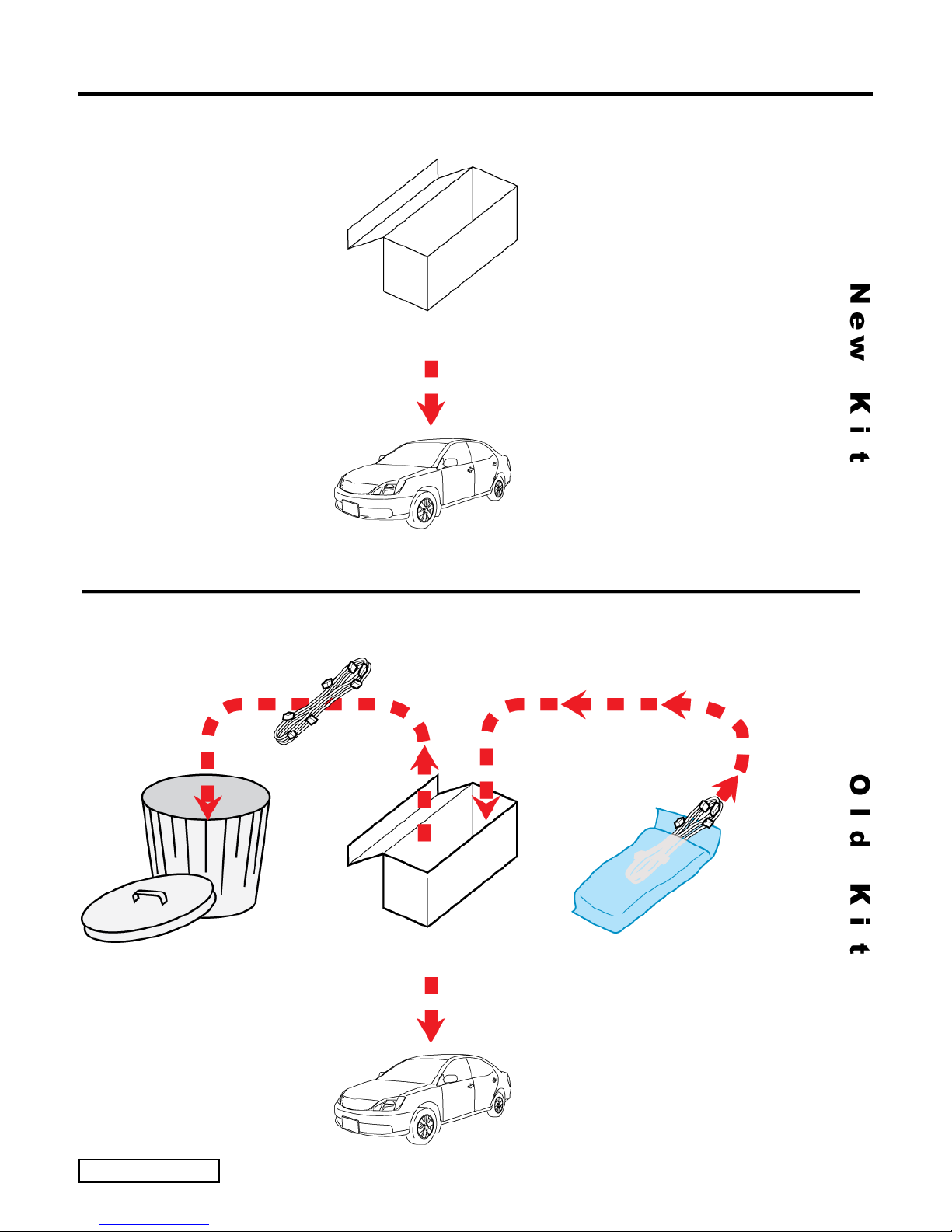
Procedure REMOTE ENGINE STARTER (RES)
PT398-60101
OLD HARNESS NEW HARNESS
PT398-60080
PT398-60090-RS
Issue: C 08/19/10
Page 2 of 27 pages
TOYOTA LAND CRUISER 2010 - TVIP V4
Procedure REMOTE ENGINE STARTER (RES)
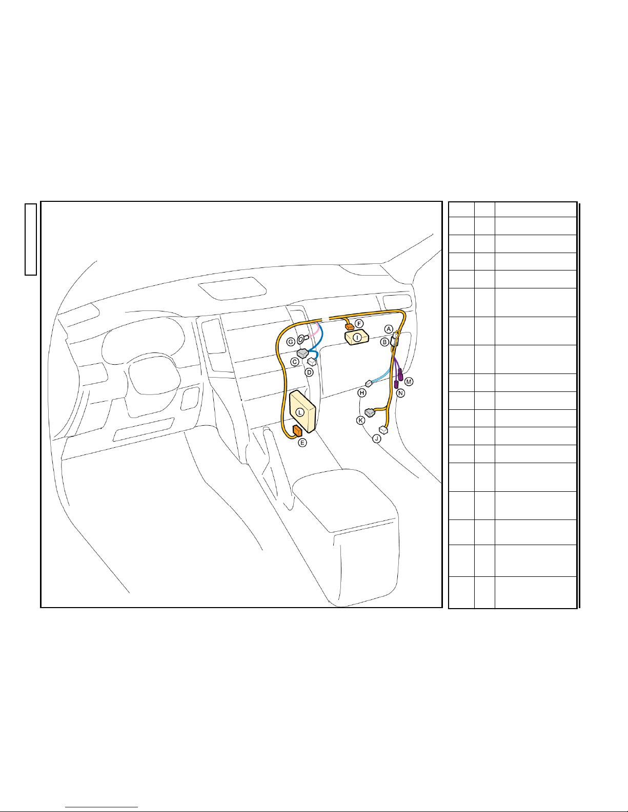
Page 3 of 27 pages
Issue: C 08/19/10
Description
5P WHITE
5P WHITE
10P WHITE
10P WHITE
20P WHITE
for RES ECU
5P WHITE
for Gateway ECU
GROUND WIRE
TERMINAL
2P WHITE
Gateway ECU
20P BLUE
20P BLUE
RES ECU
1P WHITE
(RES Diagnosis)
1P WHITE
(RES Diagnosis)
Vehicle
–
–
–
–
–
–
–
–
–
–
–
–
–
–
TVIP
A
B
C
D
E
F
G
H
I
J
K
L
M
N
TOYOTA LAND CRUISER 2010 - TVIP V4
t
Procedure REMOTE ENGINE STARTER (RES)
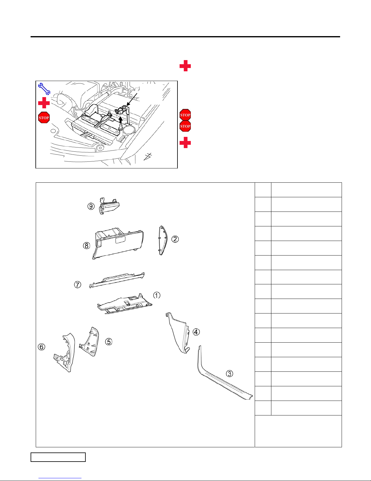
1. Vehicle Disassembly.
(a) Place the Vehicle in Park with the Parking
Brake set.
Fig. 1-1
10mm Socke
Negative
Battery
Cable
(b) Remove the Negative Battery Cable.
(Fig. 1-1)
(1) Protect the Fender before starting.
(2) Note the Battery Cable position, as it will be re-
installed in the same position.
CAUTION: Do not touch the positive terminal.
1 Glove Box Under Cover
2 PS Dash Side Cover
3 PS Step Cover
4 PS Cowl Cover
5 PS Knee Panel
6 PS Cluster Side Panel
Fig. 1-2
Fig. 1-2
7 PS Knee Airbag
8 Glove Box
9 DVD Unit
Remove all corresponding
connectors accordingly as
you disassemble.
Issue: C 08/19/10
Page 4 of 27 pages
TOYOTA LAND CRUISER 2010 - TVIP V4
N
N
N
N
Procedure REMOTE ENGINE STARTER (RES)
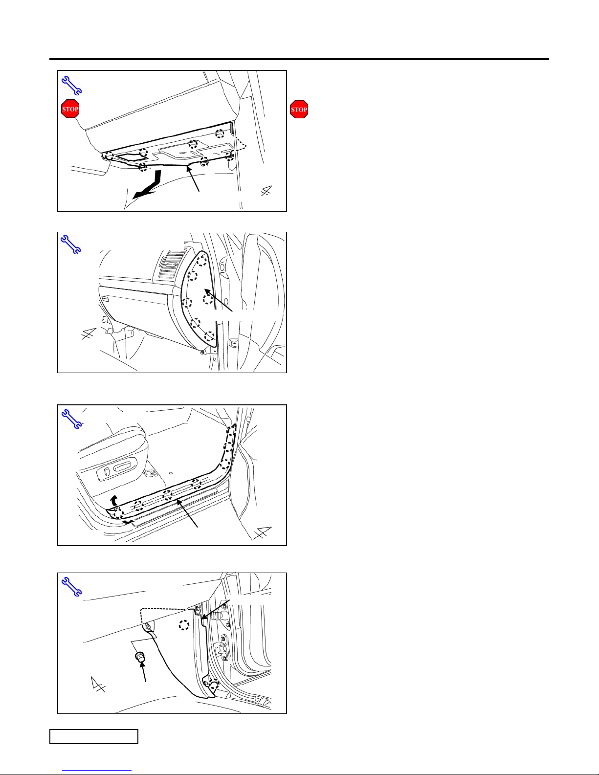
(c) Remove the Glove Box Under Cover.
ylon Panel Removal Tool
Fig. 1-3
ylon Panel Removal Tool
Glove Box Under Cover
(Fig. 1-3)
(1) Begin by protecting the Vehicle Interior with
Blankets.
(d) Remove the Passenger’s Side Dash Side.
Cover. (Fig. 1-4)
Fig. 1-4
Fig. 1-5
ylon Panel Removal Tool
ylon Panel Removal Tool
Step Cover
Dash Side Cover
Cowl Cover
(e) Remove the Passenger’s Side Step Cover.
(Fig. 1-5)
(f) Remove the Passenger’s Side Cowl Cover.
(Fig. 1-6)
(1) Remove 1 Nut.
Nut
Fig. 1-6
Issue: C 08/19/10
Page 5 of 27 pages
TOYOTA LAND CRUISER 2010 - TVIP V4
N
Procedure REMOTE ENGINE STARTER (RES)
ylon Panel Removal Tool
Fig. 1-7
Phillips Screwdriver, Nylon Panel Removal Tool
Cluster Side
Fig. 1-8
10mm Socket, Nylon Panel Removal Tool
Knee Panel
Screw
Clip
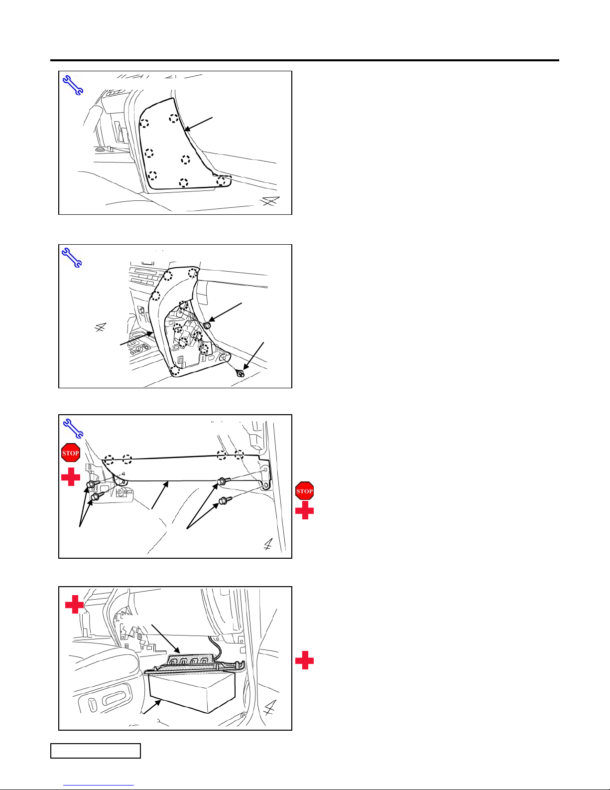
(g) Remove the Passenger’s Side Knee Panel.
(Fig. 1-7)
(h) Remove the Passenger’s Side Cluster Side
Panel. (Fig. 1-8)
(1) Remove 1 Screw and 1 Clip.
(i) Remove the Passenger’s Knee Air Bag.
Bolts (x2)
Fig. 1-9
Fig. 1-10
Fig. 1-10
Knee Air Bag
Knee Air Bag
Knee Air Bag
TVIP Box
TVIP Box
Bolts (x2)
(Fig. 1-9)
(1) Remove 4 Bolts.
(2) Do not disconnect the Vehicle’s Connector.
CAUTION: Sharp metal edges.
(j) Wrap the Passenger’s Knee Air Bag in a
Blanket and use the TVIP Kit Box to
support it. (Fig. 1-10)
CAUTION: Sharp metal edges.
Issue: C 08/19/10
Page 6 of 27 pages
TOYOTA LAND CRUISER 2010 - TVIP V4
N
Procedure REMOTE ENGINE STARTER (RES)
Phillips Screwdriver
Fig. 1-11
ylon Panel Removal Tool, 10mm Socket
Bolt
Cover
Fig. 1-12
Screws (x2)
Cover
Glove Box
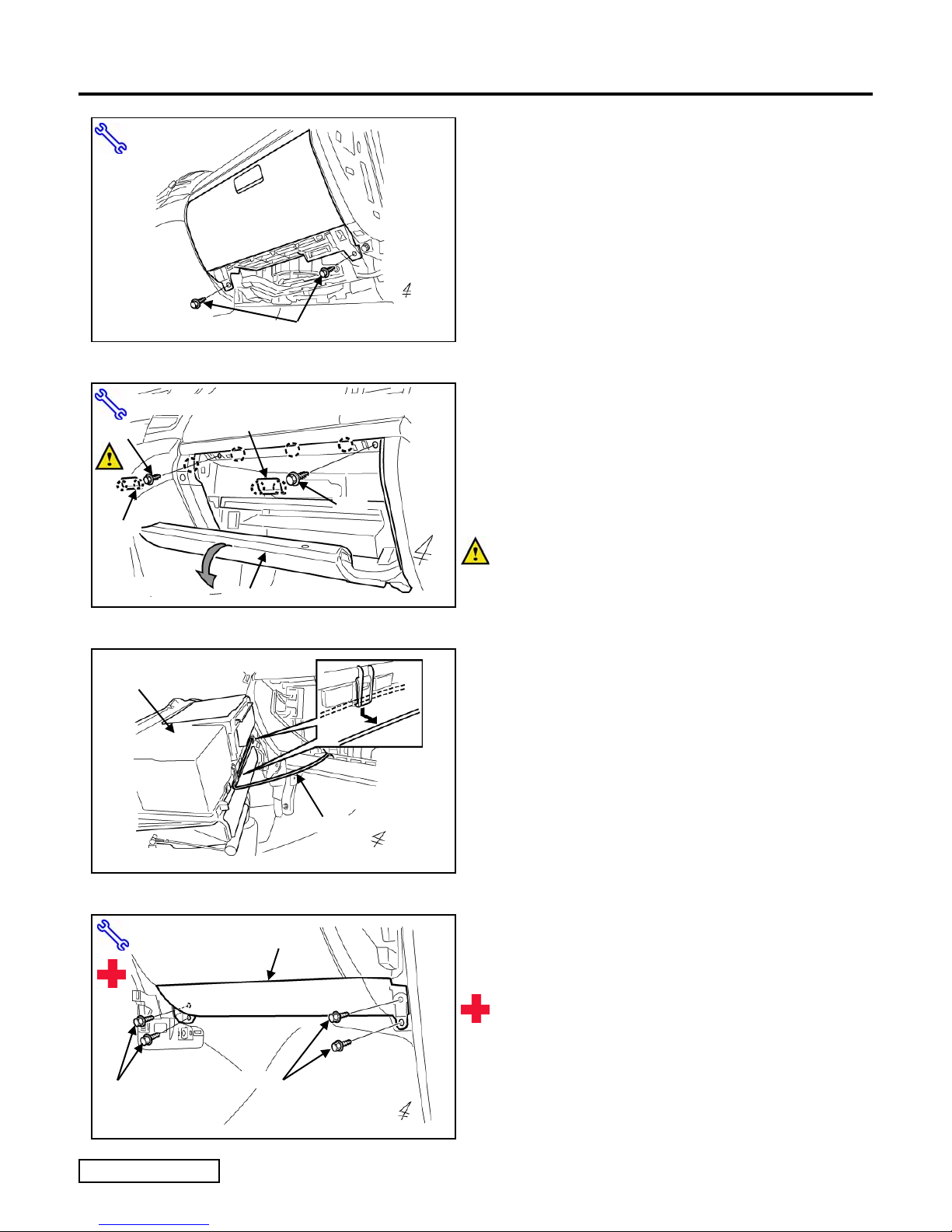
(k) Remove 2 Screws from the bottom of the
Glove Box. (Fig. 1-11)
(l) Open the Glove Box Door, then remove 2
Bolt Covers from the Glove Box.
(Fig. 1-12)
(m) Dislodge the Glove Box(Fig. 1-12)
Bolt
(1) Remove 2 Bolts.
NOTE: Pull down and out to avoid damaging
the Vehicle Clips or Dash Trim.
Glove Box
(backside)
Fig. 1-13
10mm Socket
Bolts (x2)
Knee Air Bag
Bolts (x2)
Vehicle Harness
(n) Remove the Vehicle Harness from the
backside of the Glove Box, then remove the
Glove Box. (Fig. 1-13)
(1) Disconnect any Connectors.
(o) Temporarily install the Passenger's Side
Knee Air Bag. (Fig. 1-14)
CAUTION: Sharp metal edges.
Fig. 1-14
Issue: C 08/19/10
Page 7 of 27 pages
TOYOTA LAND CRUISER 2010 - TVIP V4
Procedure REMOTE ENGINE STARTER (RES)
10mm Deep Socket, Clip Clamp Pliers, Screwdriver
Screw
Fig. 1-15
V4 Harness
Fig. 2-1
Screw
Brace
Vehicle’s Yellow Harness
DVD Unit
V4 Harness
White Tape
Nut
Clamp
VEHICLES EQUIPPED WITH
NAVIGATION SYSTEM.
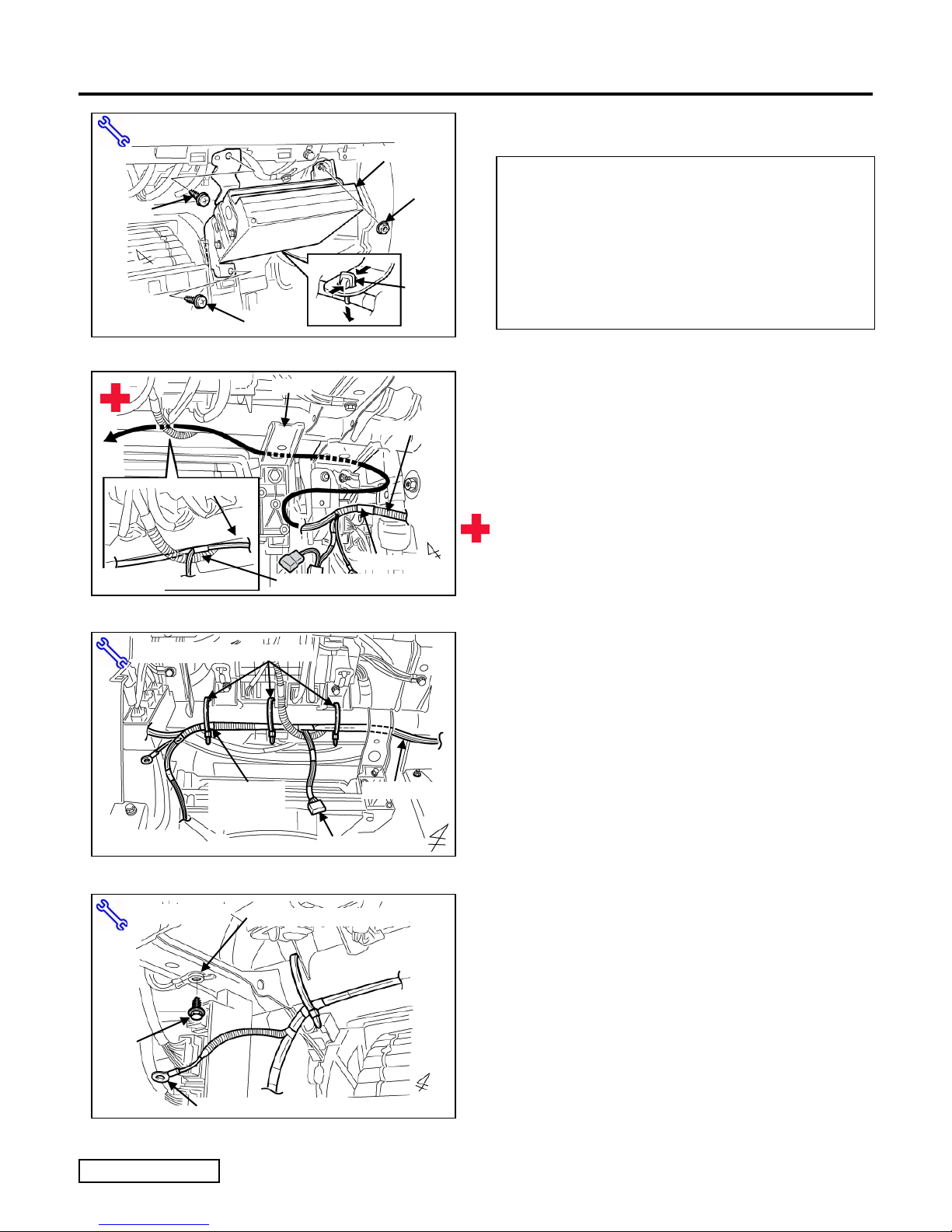
(p) Remove the DVD Unit from the Glove Box
Area. (Fig. 1-15)
(1) Remove 2 Screws and 1 Nut.
(2) Using the Clip Clamp Tool or the like, push on
the inside the Vehicle Clamp, and release it
from the DVD Unit.
2. V4 Wire Harness Installation.
(a) Route the V4 Harness behind the Vehicle
Brace and Yellow Harness in the Glove
Box area as shown. (Fig. 2-1)
CAUTION: Sharp metal edges.
Side Cutter
Fig. 2-2
10mm Socket
Bolt
Fig. 2-3
Wire Ties (x3)
V4 Harness’
White Tape
Marker
Vehicle’s Ground Terminal
V4 Harness’s Ground Terminal
V4 Harness
5P
(b) Secure the V4 Harness's White Taped
Marker to the Reinforcement with 1 Wire
Tie. (Fig. 2-2)
(c) Secure the V4 Harness to the
Reinforcement with 2 Wire Ties.
(Fig. 2-2)
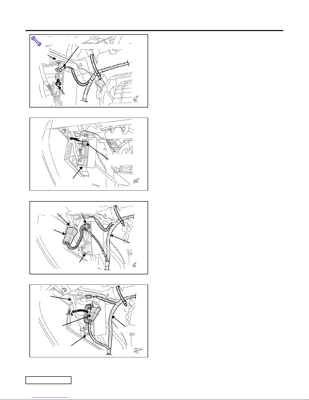
(d) Locate and remove 1 Bolt from the Vehicle
Ground Terminal in the upper left side of
the Glove Box Area. (Fig. 2-3)
(1) Do not discard the Bolt.
Issue: C 08/19/10
Page 8 of 27 pages
TOYOTA LAND CRUISER 2010 - TVIP V4
Procedure REMOTE ENGINE STARTER (RES)
10mm Socket
Vehicle's
Ground
Terminal
Fig. 2-4
Fig. 2-5
V4 Harness's Ground Terminal
Bolt
Passenger's Side
Connector Block
Vehicle’s 10P
(White)
(e) Use the existing Vehicle's Bolt to secure the
V4 Harness's Ground Terminal with the
Vehicle's Ground Terminal. (Fig. 2-4)
(1) Make sure that the Vehicle's Ground Terminal
Pin seats properly.
(f) Locate and remove the Vehicle's White 10P
Connector from the Connector Block in the
Glove Box Area. (Fig. 2-5)
Vehicle Harness'
White 10P
V4 Harness'
White 10P
Fig. 2-6
Vehicle
Harness
10P
V4 Harness'
White 10P
Passenger's Side
Connector Block
V4 Harness
V4 Harness
(g) Plug in the V4 Harness’s White 10P
Connectors in between the Vehicle
Harness’s White 10P Connector and the
Connector Block. (Fig. 2-6)
(1) Verify secure connection.
(h) Push the 10P Connectors through the
opening between the Vehicle Harness and
the Passenger's Side Connector Block as
shown. (Fig. 2-7)
Fig. 2-7
Issue: C 08/19/10
Passenger's Side
Connector Block
Page 9 of 27 pages
 Loading...