

TOYOTA RAV4 w/Smart Key 2013– TVIP V4
PREPARATION REMOTE ENGINE STARTER (RES)
Part #: PT398-42130
Conicts: Do not install into Non-Smart Vehicles and do not use Techstream Lite.
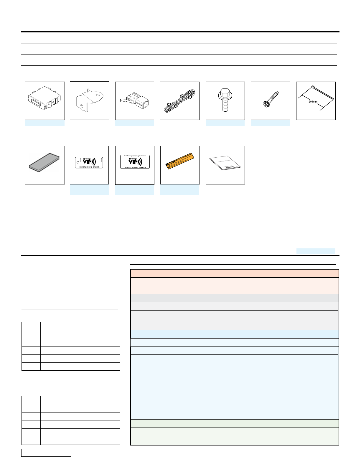
KitContents
RES ECU Hood Switch
PT398-89100-SS
Foam Tape
RES ECU Bracket
x1
x1
English x2
Spanish x2
(E) PT398-4209E
(S) PT398-4209S
x1
PT398-52080-HS
Window Label
English x2
Spanish x2
(E) 08192-07810
(S) PT398-00071-SL
V4 Harness
x1
Engine Room Label
(E) PT398-00070-EL
(S) PT398-00070-SL
x1
English x1
Spanish x1
M6 Bolt
91651-60618
Owner’s GuideKey Tag
x1
x1
Screw
(for Hood SW)
90167-T120A
Wire Tie
x1 x10
AdditionalItems
(may be required)
Item# Description
RecommendedSequence
ofApplication
Item# Description
Service Part #’s
RecommendedTools
Personal&VehicleProtection Description
Safety Glasses
Safety Gloves (Optional)
SpecialTools
Techstream Use latest version on TIS (Do not use Techstream Lite)
1/4” Drive Torque Screwdriver
(Req’d for Hood Switch)
InstallationTools
Pick Tool
Screwdriver Flat Blade Jeweler’s
Nylon Panel Removal Tool e.g. Panel Pry Tool #1 Toyota SST# 00002-06001-01
Side Cutters
Torque Wrench Battery: 48 in•lbf (5.4 N•m)
Pliers Needle Nose
Tape Clear, Electrical
Wrench 10mm
Socket 10mm, Extension
SpecialChemicals
Cleaner VDC Approved Cleaner
Glass Cleaner Household Glass Cleaner
Included in the TPMS Tool Kit# 00002-TTPWS
Toyota SST# 00002-TTPWS-03, #0 Phillips
Hood Switch: 3.1 in•lbf (0.35 N•m)
Hood Latch: 71 in•lbf (8.0 N•m)
Issue C : 04/11/13
Page 1 of 26

TOYOTA RAV4 w/Smart Key 2013– TVIP V4
PREPARATION REMOTE ENGINE STARTER (RES)
TableofContents
I. Preparation ............................................................................................................................ 1–4
1. Table of Contents ................................................................................................................................................ 2
2. Wire Routing Overview ...................................................................................................................................3-4
II. Procedure ............................................................................................................................5–23
1. Hood Switch Installation. ..............................................................................................................5
2. Vehicle Disassembly . ..................................................................................................................8
3. RES ECU Preparation and Installation. ............................................................................................ 9
4. V4 Harness Installation. .............................................................................................................. 11
5. Registration. ............................................................................................................................ 17
6. Complete the Installation. ........................................................................................................... 22
7. Tags and Labels.
III. Checklist ........................................................................................................................... 24–26
1. Accessory Function Checks .............................................................................................................................. 24
2. Vehicle Appearance Check ...............................................................................................................................24
3. Vehicle Function Checks ..............................................................................................................................25-26
....................................................................................................................... 23
Legend
Do not proceed until process has
been completed.
Follow steps carefully to avoid
damaging the Vehicle
or Accessory
Use caution to avoid injury.
Used in Figures to call attention to
specic tools recommended for the
process.
Highlights a change in installation
with respect to previous issue.
Indicates that torque is related to
safety.
Video available; click to play.
Wire Tie location and number.
xx
Issue C : 04/11/13
AccessoryInstallationPractice(readbeforeinstallation)
Care must be taken when installing this accessory to ensure damage does not
occur to the vehicle. The installation of this accessory should follow approved
guidelines to ensure a quality installation.
These guidelines can be found in the “Accessory Installation Practices”
document.
This document covers such items as:
• Vehicle Protection (use of covers and blankets, cleaning chemicals, etc.)
• Safety (eye protection, checking torque procedure, etc.)
• Vehicle Disassembly/Reassembly (panel removal, part storage, etc.)
• Electrical Component Disassembly/Reassembly (battery disconnection,
connector removal, etc.)
Please see your TOYOTA dealer for a copy of this document.
Page 2 of 26
TOYOTA RAV4 w/Smart Key 2013– TVIP V4
PREPARATION REMOTE ENGINE STARTER (RES)
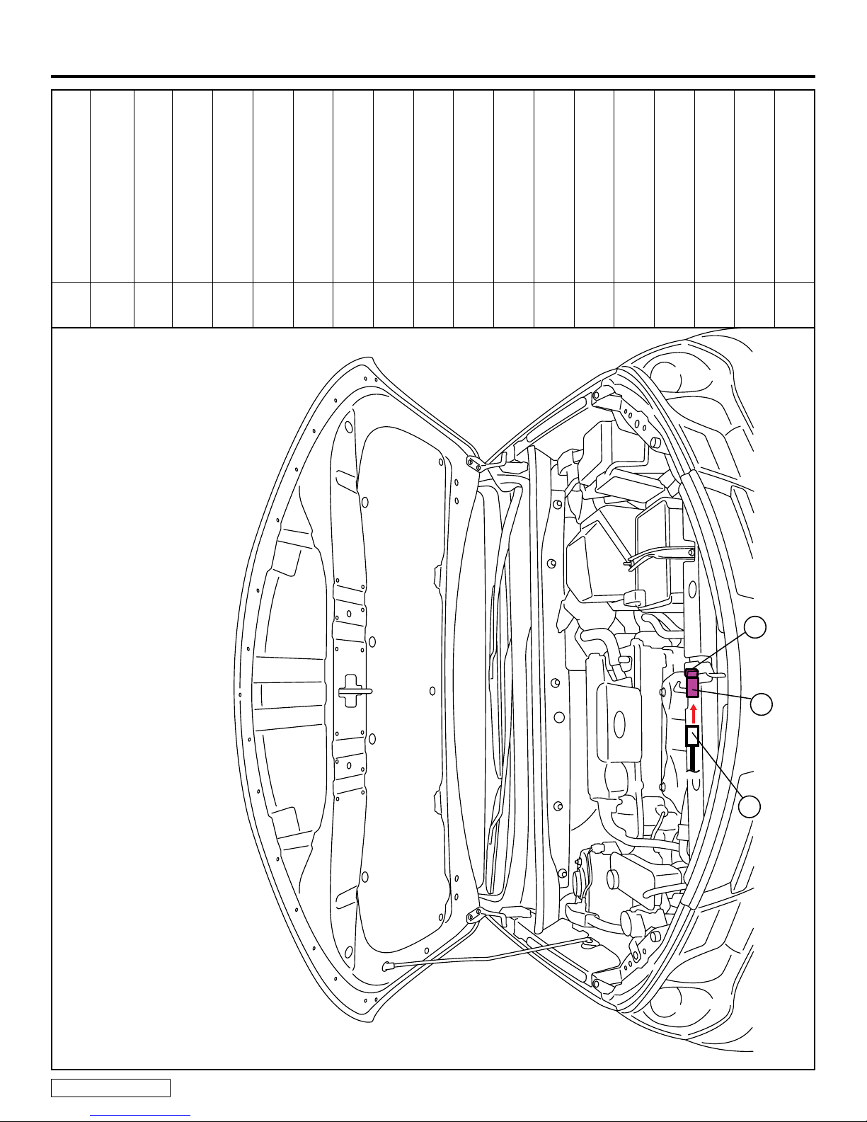
Vehicle’s 2P Black
Pre-Connector
A 2P Black
B
Y Hood Switch
Y
A
RAV4w/SmartKeyRES
EngineCompartment
Issue C : 04/11/13
B
Page 3 of 26

TOYOTA RAV4 w/Smart Key 2013– TVIP V4
PREPARATION REMOTE ENGINE STARTER (RES)
24P White
(for RES ECU)
1P White
(for Registration)
1P White
(for Registration)
White Tape
Yellow Wire
(Female Terminal)
RES ECU
TVIP Vehicle Description
A G69 5P White
B JG2 12P White
C JG2 12P White
D 3C
-
E
-
M
-
-
-
W
Z
N
RAV4w/SmartKeyRES
WireRoutingOverview
Issue C : 04/11/13
Z
Page 4 of 26
D
A
C
W
E
B
M
N

TOYOTA RAV4 w/Smart Key 2013– TVIP V4
PROCEDURE REMOTE ENGINE STARTER (RES)
1. HoodSwitchInstallation.
a. Place the Vehicle in Park with
the Parking Brake set.
b. Disconnect the Negative
Battery Terminal.
• Note the Battery Cable Position
as it will be re-installed in the
same position.
CAUTION: Do not touch the
Positive Terminal.
c. Dislodge the Hood Lock
Assembly.
• Remove 3 Bolts.
Issue C : 04/11/13
d. Remove the Hood Lock
Cable from the Hood Lock
Assemby.
Page 5 of 26

TOYOTA RAV4 w/Smart Key 2013– TVIP V4
PROCEDURE REMOTE ENGINE STARTER (RES)
Fig. 1-4
Phillips Jeweler’s Screwdriver, Torque Screwdriver Fig. 1-5
Make sure to hold the Hood
Switch by its sides.
Make sure the Hood Switch Lever
is positioned properly.
If the Hood Switch is broken,
RES will not function.
e. Install the Hood Switch with
the Switch Lever underneath
the Hood Lock Trigger Lever.
NOTE:Torque the Screw to
3.1 in•lbf (0.25~0.35 N•m).
NOTE:Do not re-use the Screw
once it is already installed. The
effect of the adhesive becomes
weak if used again.
f. Reinstall the Hood Lock
Cable to the Hood Lock
Assembly.
Issue C : 04/11/13
Page 6 of 26

TOYOTA RAV4 w/Smart Key 2013– TVIP V4
PROCEDURE REMOTE ENGINE STARTER (RES)
g. Reinstall the Hood Lock
Assembly.
NOTE: Torque the Bolts to
71 in•lbf (8.0 N•m).
h. Disconnect the Vehicle’s
Black 2P Pre-Connector.
Issue C : 04/11/13
i. Connect the Vehicle’s Black
2P Pre-Connector to the
Hood Switch Connector.
Page 7 of 26
TOYOTA RAV4 w/Smart Key 2013– TVIP V4
PROCEDURE REMOTE ENGINE STARTER (RES)
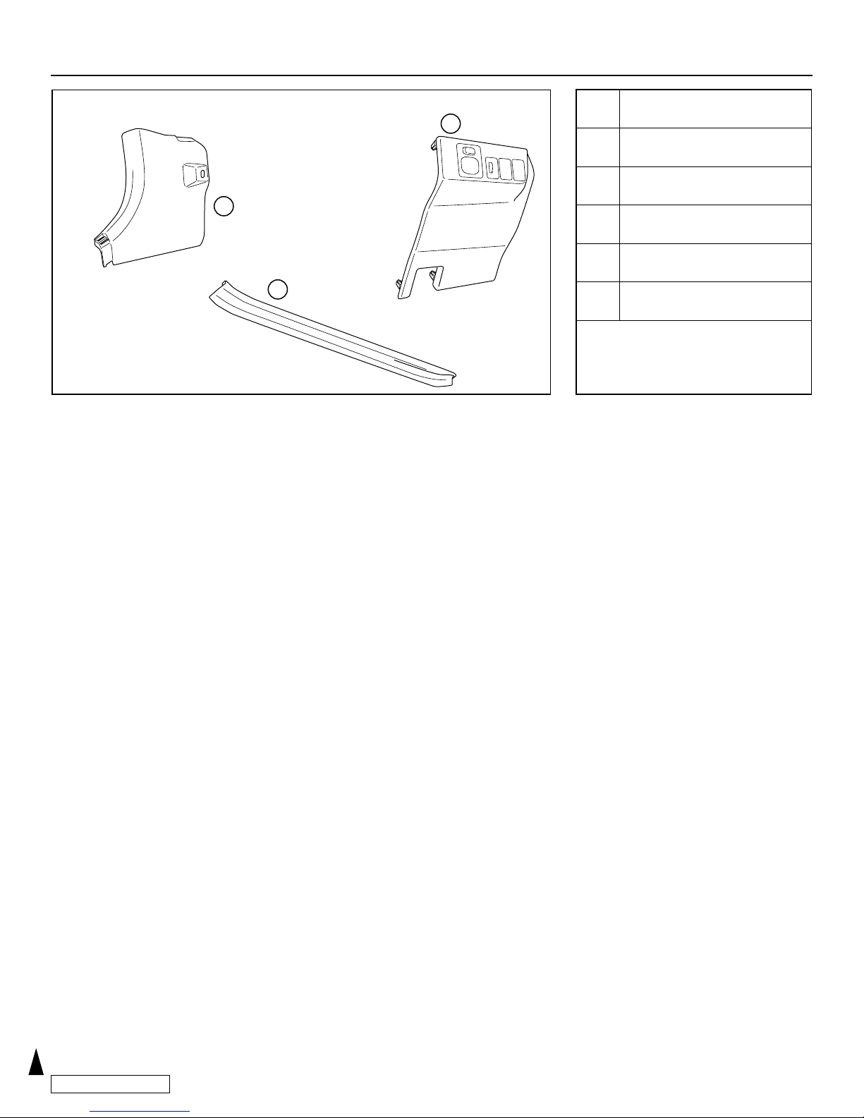
DisassemblyOverview
2
1 DS Step Cover
3
2 DS Cowl Cover
3 DS Lower Dash Cover
1
Disconnect all Corresponding
Connectors.
2. VehicleDisassembly.
a. Remove the Driver’s Side
Step Cover.
Issue C : 04/11/13
b. Remove the Driver’s Side
Cowl Cover.
• Remove 1 Nut.
Page 8 of 26
 Loading...