

TOYOTA TUNDRA 2010 - TVIP V4
Preparation REMOTE ENGINE STARTER (RES)
Part Number: PT398-00100
PT398-00100-AA
Conflicts
Do not install into vehicles without RKE system.
Recommended Sequence of Application
Item # Accessory
1 TVIP/RES Any TVIP or RES system
2 XM Radio
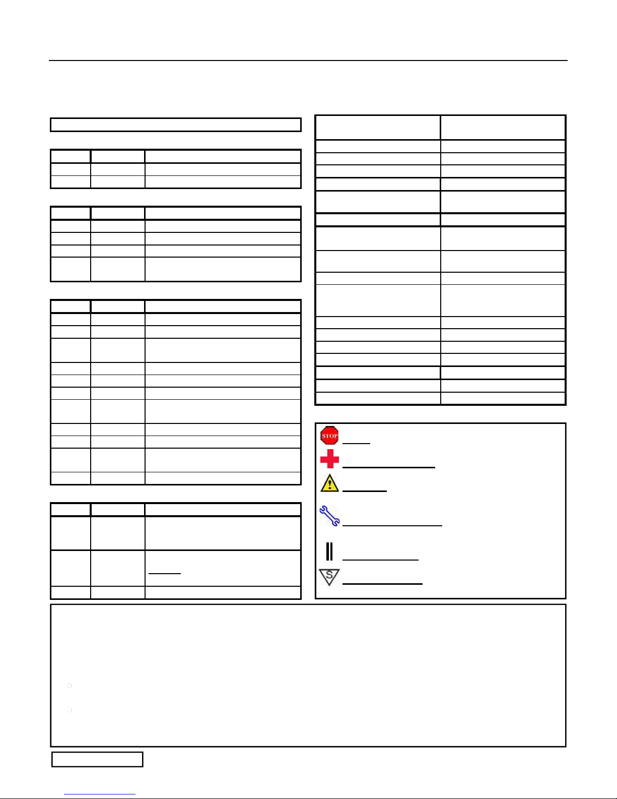
Kit Contents
Item # Quantity Description
1 1 Wire Harness
2 1 RES ECU Mounting Bracket
3 1 RES ECU Mounting Plate
4 1 Gateway ECU Bracket (See Page 2
for details)
Hardware Bag Contents
Item # Quantity Description
1 1 RES ECU
2 1 Gateway ECU
3 2-4 Small Foam Tape Strips (1 per.)
(See page 2 for details)
4 1 Large Foam Tape Strips (2 per)
5 25 Wire Ties
6 2 M6 Flange Nut
7 4 Window Warning Labels
(English/Spanish)
8 4 Key Labels (English/Spanish)
9 4 Key Tags (English/Spanish)
10 2 Engine Room Warning Labels
(English/Spanish)
11 1 Owner’s Manual
Additional Items Required For Installation
Item #
1 1 Hood Switch Kit (08586-oc920)
2 1 V4 Adapter Kit (PT398-34112)
3 1 Black Electrical Tape
Quantity Description
for vehicles without factory alarm.
(1 V4 Hood Latch, 2 Nut Covers)
NOTE: Refer to Page 18 to
determine if you will need this kit.
NOTE: Part number of this accessory may not be the same as
the part number shown.
Recommended Tools
Personal & Vehicle
Protection
Safety Glasses
Safety Gloves (Optional)
Vehicle Protection Blankets, Parts Boxes, etc.
Special Tools Notes
Terminal Tension Blade
Installation Tools Notes
Screwdriver #2 Phillips, Flat blade,
Nylon Panel Removal Tool
Side Cutters
Torque Wrench
Utility Knife
Tape Clear
Wrench 10mm
Socket 10mm, Extension
Special Chemicals Notes
Cleaner VDC Approved Cleaner
Glass Cleaner Household Glass Cleaner
Notes
Toyota SST # 00002-025BL-01
Or Sumitomo P/N 319-0000
Jeweler's
e.g. Panel Pry Tool #1 Toyota
SST # 00002-06001-01
36 in•lbf (4.7 N•m),
71 in•lbf (8 N•m),
88.5 in•lbf (10 N•m)
Legend
STOP: Damage to the vehicle may occur. Do not
proceed until process has been complied with.
OPERATOR SAFETY: Use caution to avoid risk of
injury.
CAUTION: A process that must be carefully observed
in order to reduce the risk of damage to the
accessory/vehicle and to ensure a quality installation.
TOOLS & EQUIPMENT: Used in Figures calls out the
specific tools and equipment recommended for this
process.
REVISION MARK: This mark highlights a change in
installation with respect to previous issue.
SAFETY TORQUE: This mark indicates that torque is
related to safety.
Care must be taken when installing this accessory to ensure damage does not occur to the vehicle. The installation of this
accessory should follow approved guidelines to ensure a quality installation.
These guidelines can be found in the "Accessory Installation Practices" document.
This document covers such items as:
Vehicle Protection (use of covers and blankets, cleaning chemicals, etc.)
Safety (eye protection, rechecking torque procedure, etc.)
Vehicle Disassembly/Reassembly (panel removal, part storage, etc.)
Electrical Component Disassembly/Reassembly (battery disconnection, connector removal, etc.)
Please see your Toyota dealer for a copy of this document.
Issue: E 04/07/10
Page 1 of 42 pages
TOYOTA TUNDRA 2010 - TVIP V4
Procedure REMOTE ENGINE STARTER (RES)
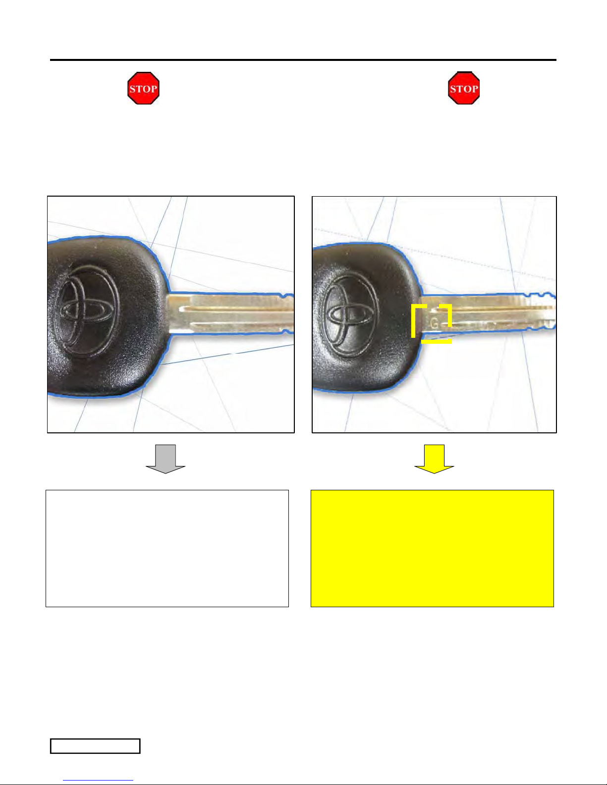
CAUTION: This kit will only work for Phase 3 Vehicles.
If the Vehicle is Phase 4 you will need to use PT398-34110. See below for how to identify Phase 3 and Phase 4
If the Vehicle’s Key does not have “G”
engraved on it
1. You can use this kit and installation
instructions.
Issue: E 04/07/10
Page 2 of 44 pages
If the Vehicle’s Key has “G”
engraved on it:
1. You
use Kit PN: PT398-34110
MUST
2. Please order the correct kit and use the
corresponding instructions.

TOYOTA TUNDRA 2010 - TVIP V4
Procedure REMOTE ENGINE STARTER (RES)
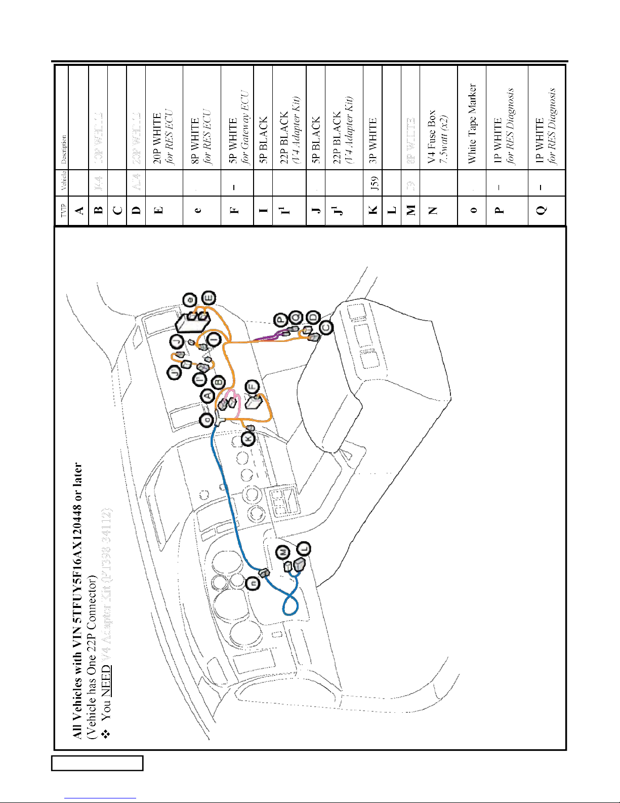
CAUTION: There are three kits available for the 10MY Tundra.
Two of the Kits have the same part number but different contents. The third Kit has a –AA part number.
Issue: E 04/07/10
Page 3 of 44 pages

TOYOTA TUNDRA 2010 - TVIP V4
Procedure REMOTE ENGINE STARTER (RES)
Issue: E 04/07/10
Page 4 of 44 pages
TOYOTA TUNDRA 2010 - TVIP V4
Procedure REMOTE ENGINE STARTER (RES)
Issue: E 04/07/10
Page 5 of 44 pages
TOYOTA TUNDRA 2010 - TVIP V4
Procedure REMOTE ENGINE STARTER (RES)
Issue: E 04/07/10
Page 6 of 44 pages
TOYOTA TUNDRA 2010 - TVIP V4
t
Procedure REMOTE ENGINE STARTER (RES)
1. Vehicle Disassembly. (Driver’s Side)
(a) Place the Vehicle in Park and set the
Parking Brake before disconnecting the
Battery.
ELECTRONIC TILT ADJUST ONLY: Fully
extend the Steering Wheel’s Tilt and Telescope
positions.
10mm Socke
Negative
Battery
Cable
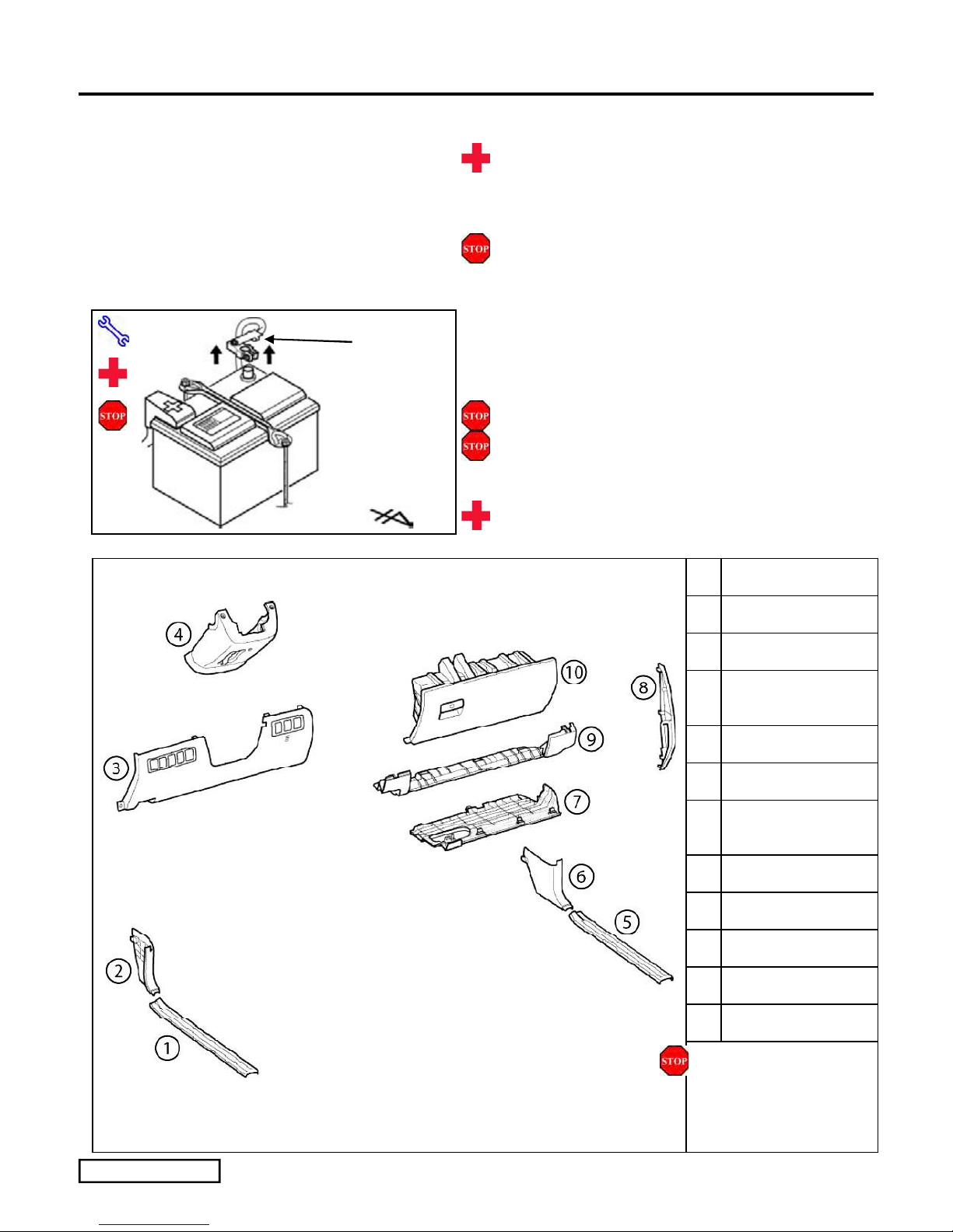
(b) Remove the Negative Battery Cable.
(Fig. 1-1)
(1) Protect the Fender before starting.
(2) Note the Battery Cable position, as it will be re-
installed in the same position.
Fig. 1-1
CAUTION: Do not touch the positive terminal.
1 DS Step Cover
2 DS Cowl Cover
3 Lower Dash Cover
4 Lower Steering
Column Cover
5 PS Step Cover
6 PS Cowl Cover
7 Glove Box Under
Cover
8 PS Dash Side Cover
9 PS Airbag Trim
10 Glove Box
Fig. 1-2
Issue: E 04/07/10
Remove all corresponding
connectors accordingly
during the process.
Page 7 of 44 pages
TOYOTA TUNDRA 2010 - TVIP V4
N
N
Procedure REMOTE ENGINE STARTER (RES)
ylon Panel Removal Tool
Fig. 1-3
Nylon Panel Removal Tool
Cowl Cover
Cowl Nut
Step Cover
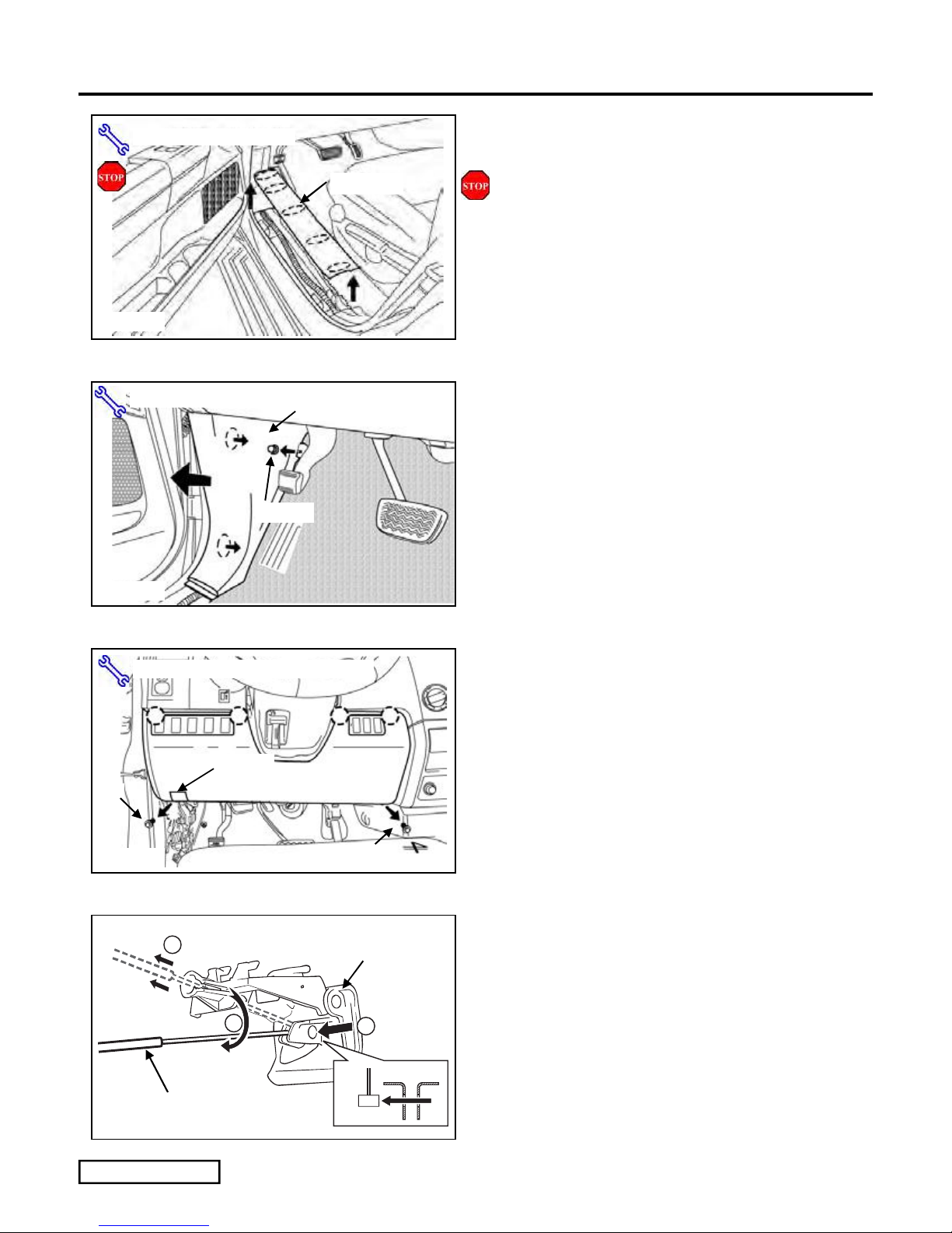
(c) Remove the Driver’s Side Step Cover.
(Fig. 1-3)
(1) Begin by protecting the Vehicle Interior with
Blankets.
(d) Remove the Driver’s Side Cowl Cover.
(Fig. 1-4)
(1) Remove 1 nut.
Fig. 1-4
ylon Panel Removal Tool, 10mm Socket
Hood Release Lever
Bolt
Fig. 1-5
1
2
Bolt
Hood Release Lever
3
(e) Dislodge the Lower Dash Cover. (Fig. 1-5)
(1) Remove 2 bolts.
(2) Disconnect all connectors.
(f) Remove the Hood Latch Cable from the
Hood Latch Lever. (Fig. 1-6)
(g) Remove the Lower Dash Cover.
Hood Latch Cable
Fig. 1-6
Issue: E 04/07/10
Page 8 of 44 pages
TOYOTA TUNDRA 2010 - TVIP V4
r
Procedure REMOTE ENGINE STARTER (RES)
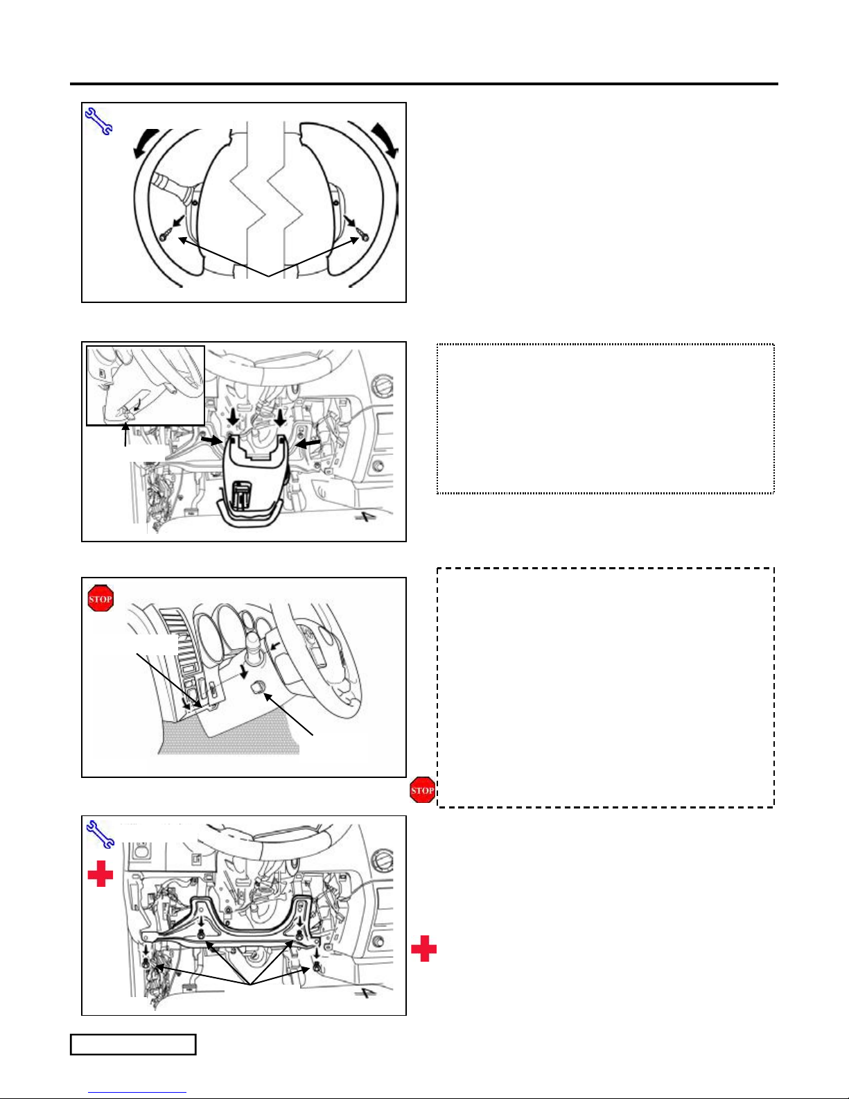
(h) Remove the 2 Screws that secure the Lower
Phillips Screwdriver
Steering Column Cover. (Fig. 1-7)
(1) Insert the key into the Ignition and turn it to
“ON.”
(2) Turn the Steering Wheel left then right to gain
access to the 2 screws securing the Cover.
Fig. 1-7
Tilt Lever
Fig. 1-8
Pull Here First
Screws (X2)
FOR USE ON VEHICLES WITH MANUAL
TILT ADJUST (steps i-j)
(i) Release the Tilt Lever. (Fig. 1-8)
(j) Press inwards on each side of the Steering
Column Cover while pulling downward to
remove the cover. (Fig. 1-8)
FOR USE ON VEHICLES WITH
ELECTRONIC TILT ADJUST (steps k-l)
(k) Press in on each side and pull down on the
lower section of the Lower Steering
Column Cover to release it from the Top
Section. (Fig. 1-9)
(l) Pull out on the Top Left Corner of the
Fig. 1-9
10mm Socket
Fig. 1-10
Issue: E 04/07/10
Bolts (x4)
Electronic
Adjuste
Steering Column Cover to clear the
Electronic Steering Column Adjuster Knob.
(Fig. 1-9)
CAUTION: Avoid scratching the vehicle.
(m) Dislodge the Driver’s Side Knee Airbag.
(Fig. 1-10)
(1) Remove 4 Bolts.
(2) Remove the Vehicle’s Diagnostic Connector.
CAUTION: Sharp metal edges.
Page 9 of 44 pages
TOYOTA TUNDRA 2010 - TVIP V4
Ny
N
Procedure REMOTE ENGINE STARTER (RES)
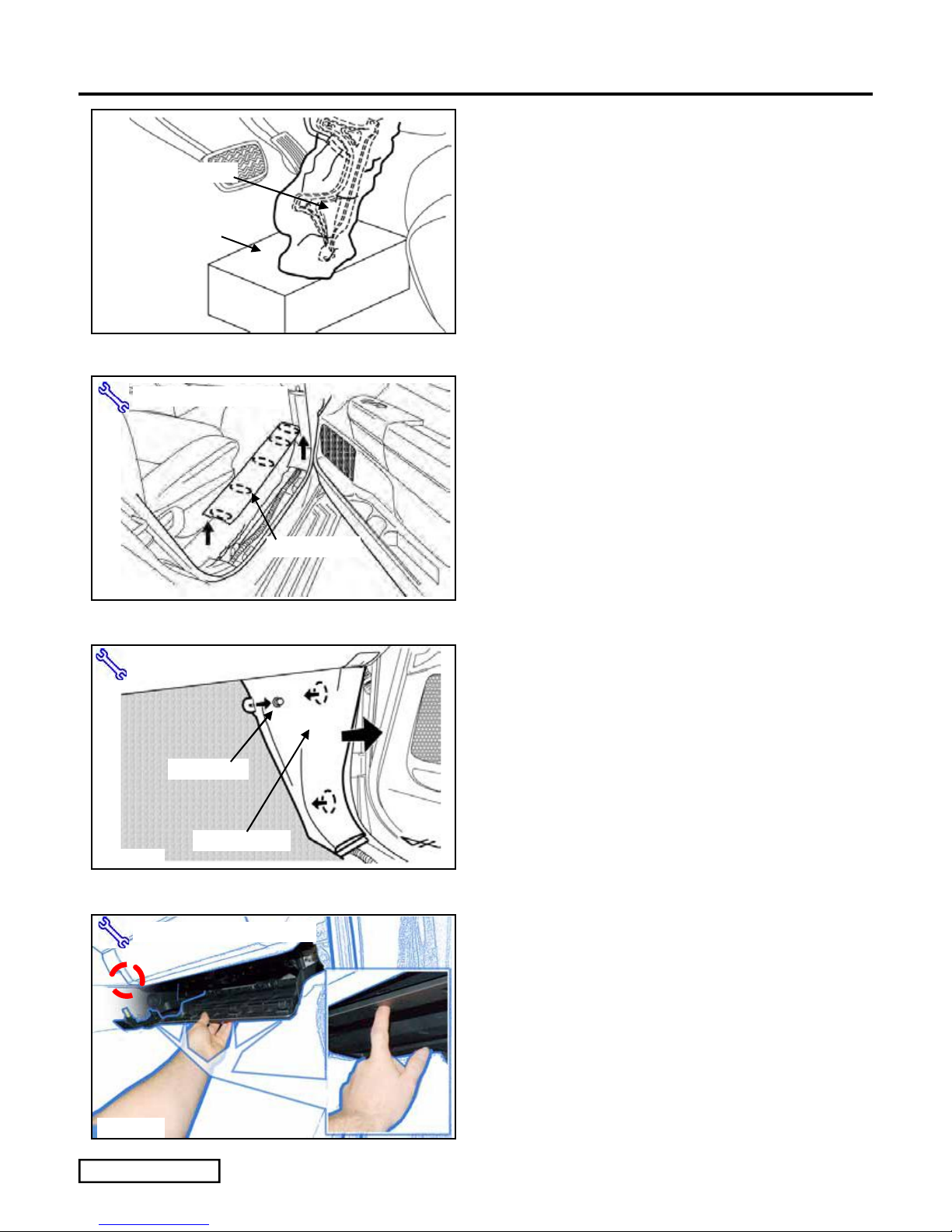
(n) Wrap the Airbag in a blanket and place on a
box to avoid tension on the harness.
Metal Substructure
TVIP Box
Fig. 1-11
ylon Panel Removal Tool
Fig. 2-1
(Fig. 1-11)
2. Vehicle Disassembly. (Passenger’s Side)
(a) Remove the Passenger’s Step Cover.
(Fig. 2-1)
Step Cover
lon Panel Removal Tool
Cowl Nut
Cowl Cover
Fig. 2-2
Nylon Panel Removal Tool
(b) Remove the Passenger’s Cowl Cover.
(Fig. 2-2)
(1) Remove 1 Nut.
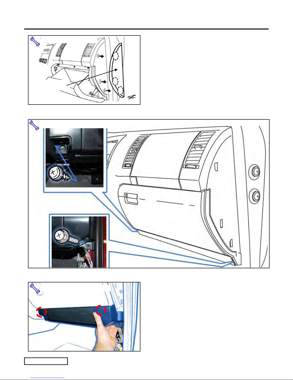
(c) Remove the Glove Box Under Cover.
(Fig. 2-3)
Fig. 2-3
Issue: E 04/07/10
Page 10 of 44 pages
TOYOTA TUNDRA 2010 - TVIP V4
Ny
Procedure REMOTE ENGINE STARTER (RES)
(d) Open the Glove Box. (Fig. 2-4)
lon Panel Removal Tool
(e) Remove the Passenger’s Dash Side Cover.
(Fig. 2-4)
(f) Close the Glove Box.
Dash Side
Cover
Fig. 2-4
10mm Socket, Phillips Screwdriver
Fig. 2-5
Nylon Panel Removal Tool
Fig. 2-6
Issue: E 04/07/10
(g) Remove 1 Screw and 1 Bolt from the
Passenger’s Side Knee Airbag Brace Trim.
(Fig. 2-5)
(h) Remove the Passenger’s Side Knee Airbag
Brace Trim. (Fig. 2-6)
Page 11 of 44 pages
TOYOTA TUNDRA 2010 - TVIP V4
Procedure REMOTE ENGINE STARTER (RES)
10mm Socket
Fig. 2-7
Fig. 2-8
10mm Socket, Phillips Screwdriver
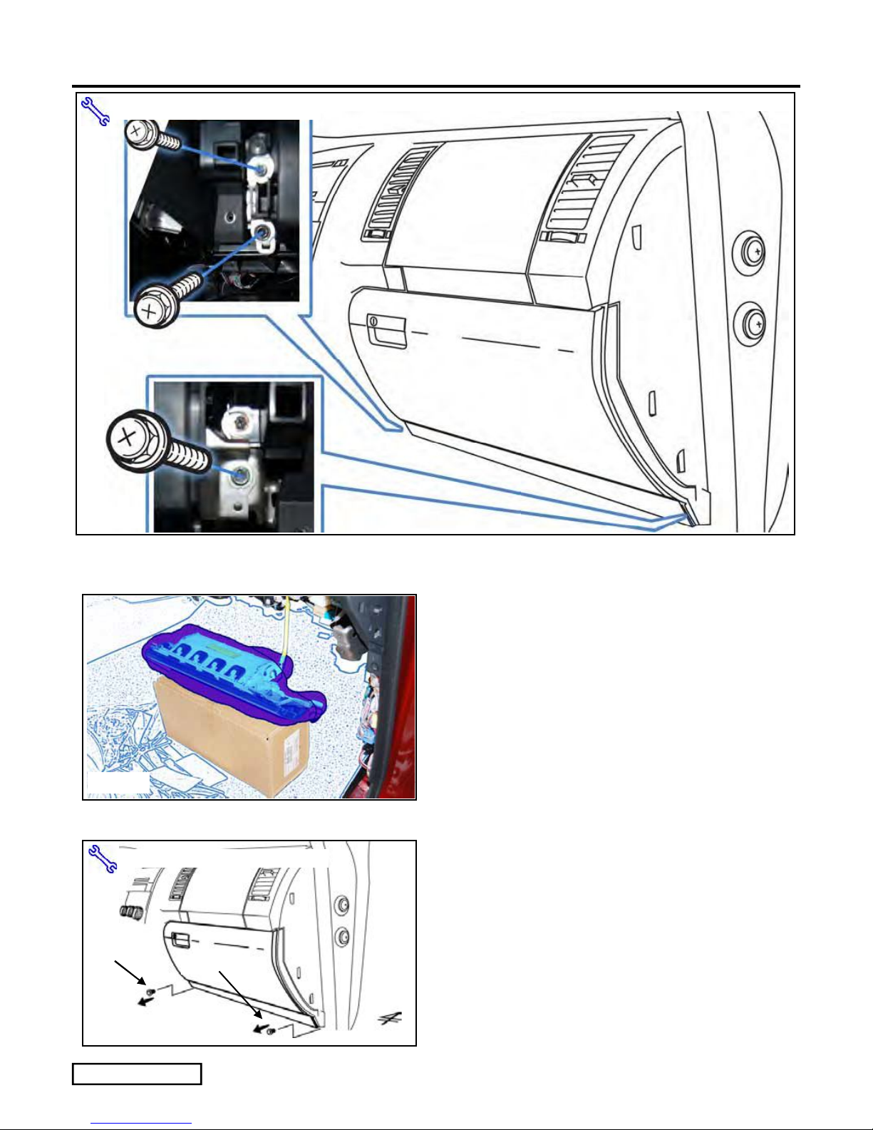
(i) Dislodge the Passenger’s Knee Airbag. (Fig.
2-7)
(1) Remove 3 Bolts.
(j) Wrap the Airbag in a blanket and place on a
box to avoid tension on the harness.
(Fig. 2-8)
(k) Remove 1 Screw and 1 Bolt from the
bottom of the Glove Box. (Fig. 2-9)
(1) Close the Glove Box.
Screw
Bolt
Fig. 2-9
Issue: E 04/07/10
Page 12 of 44 pages
TOYOTA TUNDRA 2010 - TVIP V4
Procedure REMOTE ENGINE STARTER (RES)
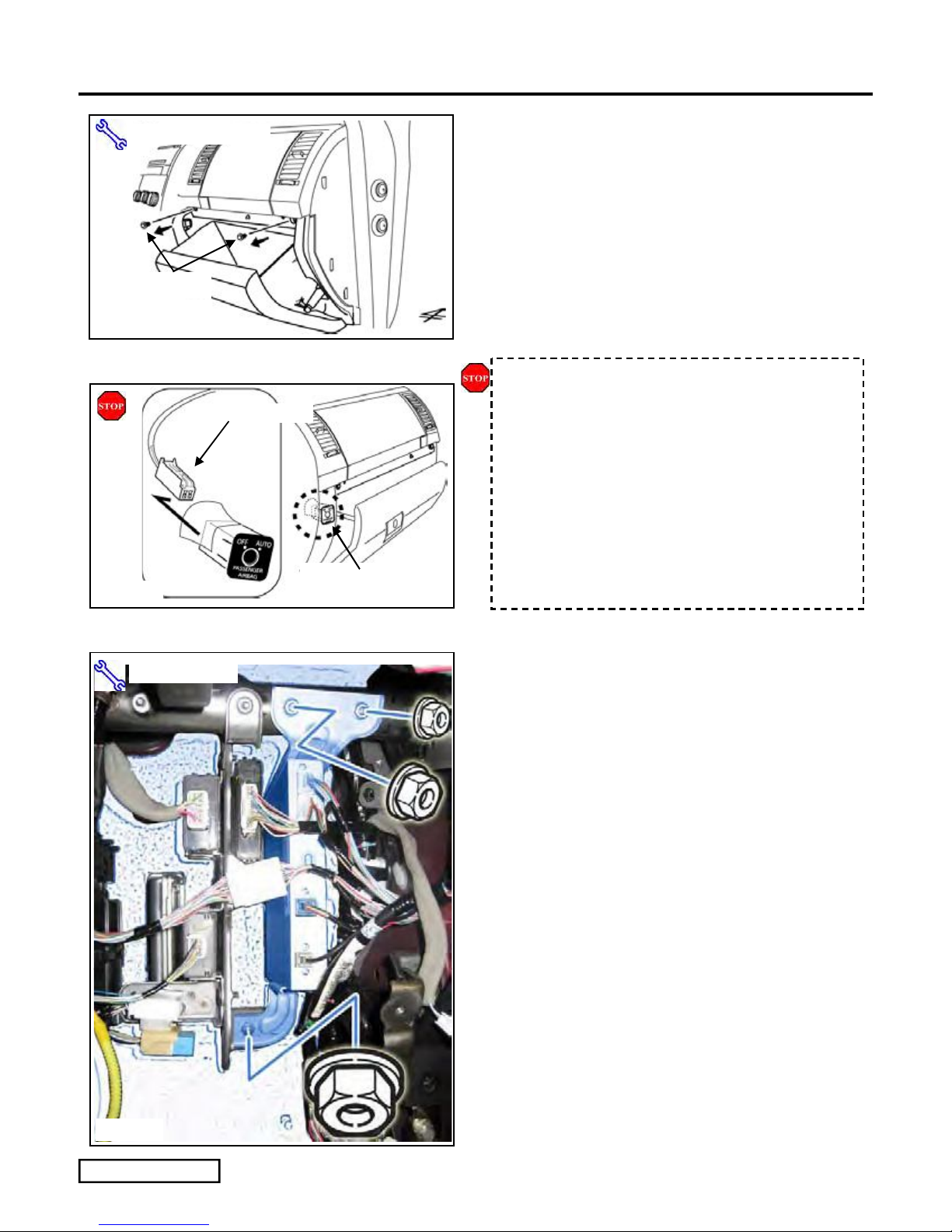
(l) Remove the Glove Box. (Fig. 2-10)
Phillips Screwdriver
Screws (x2)
Fig. 2-10
FOR USE ON B-CAB VEHICLES (step m)
2P Connector
(1) Open the Glove Box.
(2) Remove 2 Screws.
CAUTION: Verify that the negative battery
terminal is disconnected.
(m) Disconnect the Vehicle 2P Connector from
the Passenger’s Airbag Switch. (Fig. 2-11)
Fig. 2-11
10mm Socket
Passenger’s Airbag
Switch
(n) Remove the Vehicle’s ECU. (Fig. 2-12)
(1) Remove 3 Nuts.
Fig. 2-12
Issue: E 04/07/10
Page 13 of 44 pages
TOYOTA TUNDRA 2010 - TVIP V4
[1]
r
Procedure REMOTE ENGINE STARTER (RES)
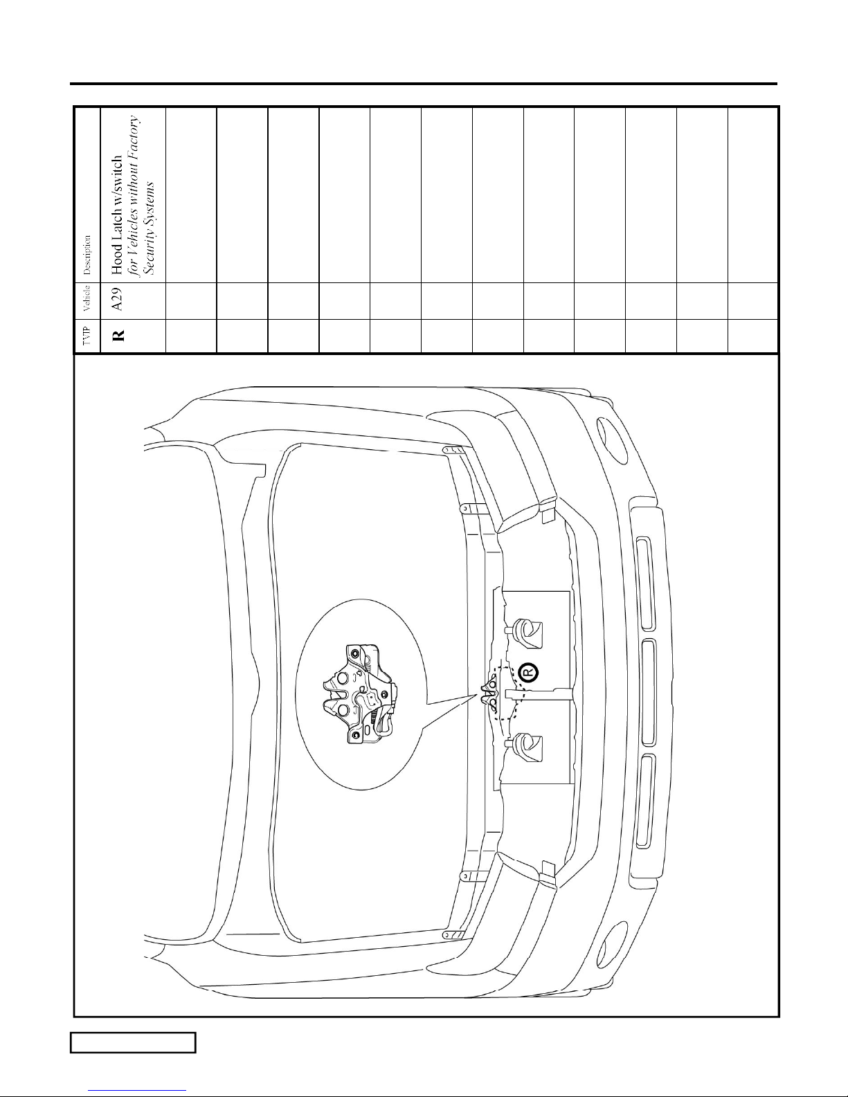
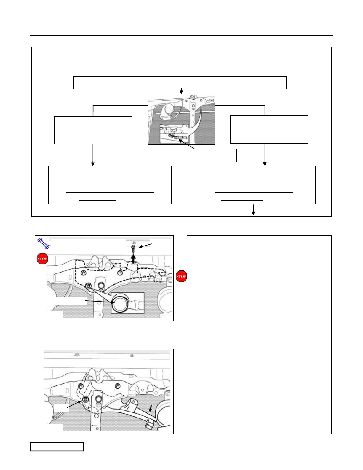
Confirm the following:
Does the Vehicle have a Hood Switch Installed?
If the Hood Switch
2P Connector is connected,
the Hood Switch is already
installed.
[2] Does not need
Hood Latch Replaced.
Skip to Section 4 V4 Harness
Installation. (pg. 15)
Flat Blade & Phillips Screwdriver
If the Hood Switch 2P
Connector is not connected,
install the Hood Switch.
Hood Switch Pre-wire
2P Connecto
[2] You must Replace Hood Switch.
Hood Switch Kit is Required.
Use Section 3 Hood Latch
Replacement. (pg. 12)
3. Hood Latch Replacement. (steps a-o)
Screw
(a) Loosen the Plastic Cover from the Hood
Latch Unit. (Fig. 3-1)
CAUTION: Protect the Radiator.
(1) Remove 1 Screw from the Top.
Nut Cover
Fig. 3-1
Nut
Fig. 3-2
Issue: E 04/07/10
(2) Remove the Nut Cover.
(3) Discard the Nut Cover.
(b) Angle the Plastic Cover downward.
(Fig. 3-2)
Page 14 of 44 pages
 Loading...