

Toyota Cressida 1991 User Manual

FOREWORD
This repair manual covers Disassembly, Inspection and Assembly procedures for the following Automatic Transmissions:
Automatic Transmission
A340E
A340F
A340H
For On−vehicle Servicing (Inspection, Adjustment, Troubleshooting, Removal and Installation) of Automatic Transmission,
refer to the repair manual for the applicable vehicle model.
Pub. Name
’91 Supra Repair Manual
’91 Cressida Repair Manual
’91 Truck Repair Manual
’91 4 runner Repair Manual
All information contained in this manual is the most up−to−
date at the time of publication. However, specifications and
procedures are subject to change without notice.
TOYOTA MOTOR CORPORATION
Applicable Model
’91 Supra, ’91 Cressida
’91 Truck, ’91 4 runner
”91 Truck, ”91 4 runner
’91 Truck, ’91 4 runner
Pub. No.
RM198U
RM200U
RM201U2
RM202U2
IN−2
−INTRODUCTION How to Use This Manual
HOW TO USE THIS MANUAL
To assist you in finding your way through the manual, the
Section Title and major heading are given at the top of every
page.
REPAIR PROCEDURES
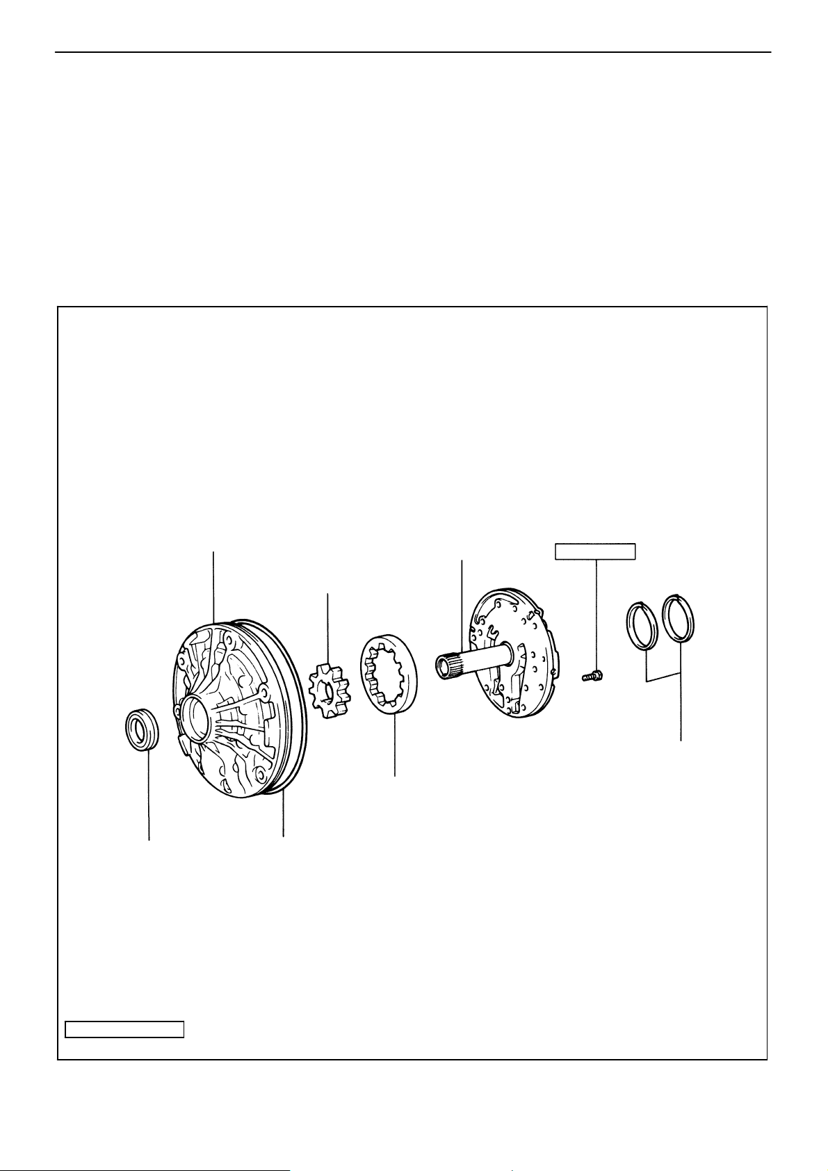
Most repair operations begin with an overview illustration. It
identifies the components and shows how the parts fit together.
Example:
♦ Oil Seat
Oil Pump Body
Oil Pump Driven Gear
Oil Pump Drive Gear
♦ O−Ring
Startor Shaft
100 (7, 10)
Oil Seal Ring
kg−cm (ft−Ib, N−m)
♦ Non−reusable part
: Specified torque
AT5461

−INTRODUCTION How to Use This Manual
The procedures are presented in a step−by−step format:
S Illustration shows what to do and where to do it.
S The task heading tells what to do.
S The detailed text tells how to perform the task and
gives other information such as specifications and
warnings.
IN−3
Illustration:
What to do and where
Example:
Task heading: what to do
7. CHECK PISTON STROKE OF FORWARD CLUTCH
If replacing the disc, plate or flange, check the piston
stroke:
Detail text: how to do it
Using a dial indicator (long type pick or SST), measure
the forward clutch piston stroke applying and releasing
the compressed air (4 − 8 kg/cm
2
or 57 − 114 psi or
392 − 785 kPa) as shown.
SST 09350−32014 (09351−32190)
Set part No.
Component part No.
Piston stroke: 1.41 − 1.82 mm (0.0555 − 0.0717 in.)
Specification
This format provides the experienced technician with a FAST
TRACK to the information needed. The upper case task heading can be read at a glance and only when necessary, the text
below it provides detailed information. Important specifications
and warnings always stand out in bold type.
REFERENCES
References have been kept to a minimum. However, when
they are required you are given the page to go to.
SPECIFICATIONS
Specifications are presented in bold type throughout the text in
the applicable step. You never have to leave the procedure to
look up your specs. All specifications are also found in Appendix A, specifications for quick reference.
CAUTIONS, NOTICES, HINTS:
S CAUTIONS are presented in bold type, and indicate
there is a possibility of injury to you or other people.
S NOTICES are also presented in bold type, and indicate
the possibility of damage to the components being repaired.
S HINTS are separated from the text but do not appear in
bold. They provide additional information to help you efficiently perform the repair.
IN−4
Seal Lock Adhesive
IN0036
−INTRODUCTION General Repair Instructions
GENERAL REPAIR INSTRUCTIONS
1. Use fender, seat and floor covers to keep the vehicle
clean and prevent damage.
2. During disassembly, keep parts in order to facilitate
reassembly.
3. Observe the following:
(a) Before performing electrical work, disconnect the
negative cable four the battery terminal.
(b) If it is necessary to disconnect the battery for in-
spection or repair, always disconnect the cable from
the negative (−) terminal which is grounded to the
vehicle body.
(c) To prevent damage to the battery terminal post,
loosen the terminal nut and raise the cable straight
up without twisting it or prying it.
(d) Clean the battery terminal posts and cable termi-
nals with a shop rag. Do not scrape them with a file
or other abrasive object.
(e) Install the cable terminal to the battery post with the
nut loose, and tighten the nut after installation. Do
not use a hammer or such to tap the terminal onto
the post.
(f) Be sure the cover for the positive (+) terminals are
properly in place.
4. Check hoses and wiring connectors to make sure
that they are secure and correct.
5. Non−reusable parts
(a) Always replace cotter pins, gaskets, O−rings and oil
seals etc. with new ones.
(b) Non−reusable parts are indicated in the component
illustrations by the ”♦” symbol.
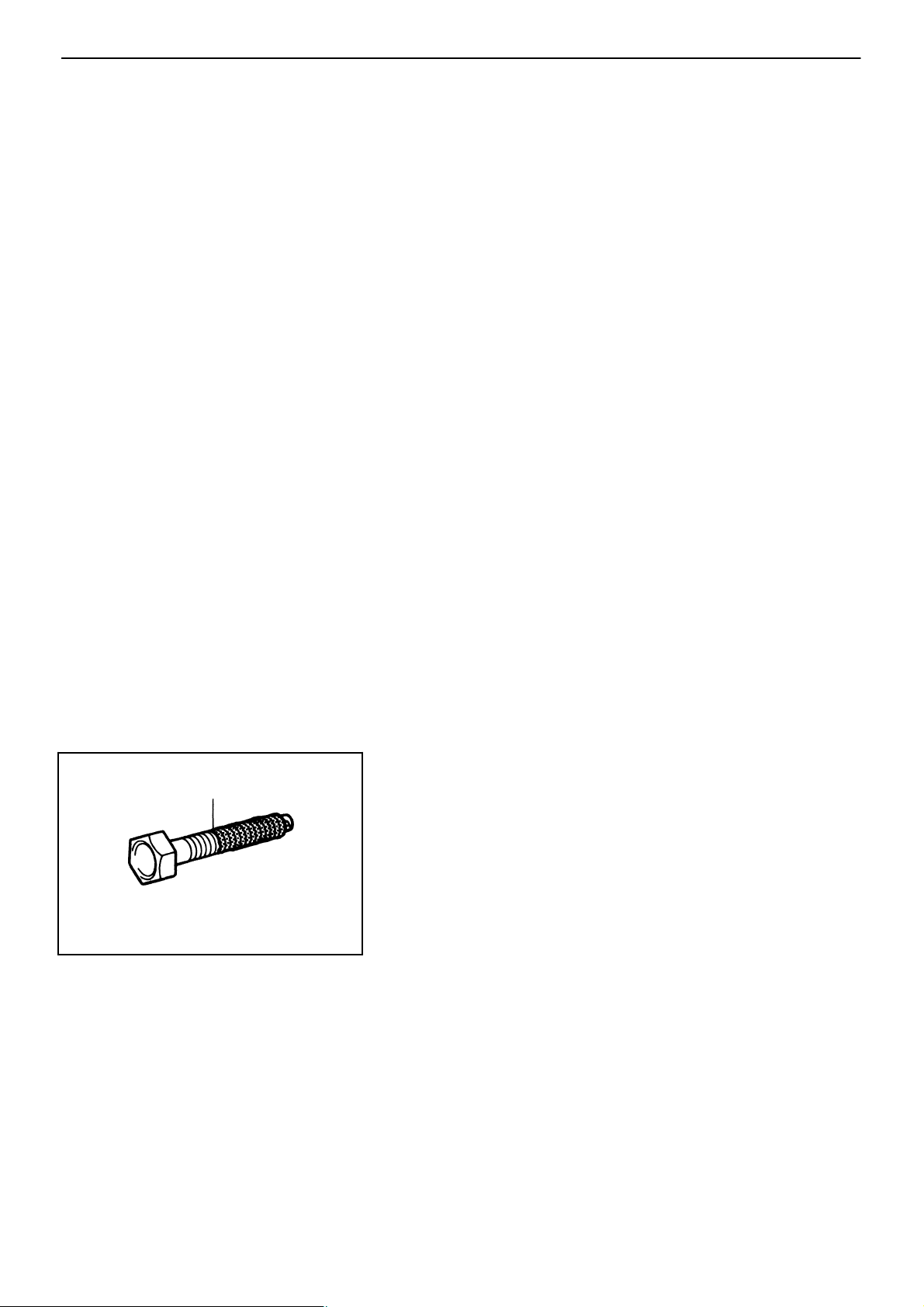
6. Precoated parts
Precoated parts are the bolts and nuts, which have
been coated with a seal lock adhesive at the factory.
(a) If a precoated part is retightened, loosened or
caused to move in any way, it must be recoated
with the specified adhesive.
(b) Recoating of precoated parts
(1) Clean off the old adhesive from the bolt, nut
or installation part threads.
(2) Dry with compressed air.
(3) Apply the specified seal lock adhesive to the
bolt or nut threads.
(c) Precoated parts are indicated in the component il-
lustrations by the ”L” symbol.

−INTRODUCTION General Repair Instructions
IN−5
7. When necessary, use a sealer on gaskets to prevent
leaks.
8. Carefully observe all specifications for bolt tightening torques. Always use a torque wrench.
9. Use of special service tools (SST) and special service materials (SSM) may be required, depending on
the nature of the repair. Be sure to use SST and SSM
where specified and follow the proper work procedure. A list of SST and SSM can be found at the back
of this manual.
10. When replacing fuses, be sure the new fuse has the
correct amperage rating. DO NOT exceed the fuse
amp rating or use one of a lower rating.
11. Care must be taken when jacking up and supporting
the vehicle. Be sure to lift and support the vehicle at
the proper locations.
(a) If the vehicle is to be jacked up only at the front or
rear end, be sure to block the wheels in order to
ensure safety.
(b) After the vehicle is jacked up, be sure to support it
on stands. It is extremely dangerous to do any
work on the vehicle raised on jack alone, even for a
small job that can be finished quickly.

IN−6
−INTRODUCTION Abbreviations Used in This Manual
ABBREVIATIONS USED IN THIS MANUAL
ADD Automatic Disconnecting Differential
A/T ATM Automatic Transmission
ATF Automatic Transmission Fluid
B
Overdrive Brake
0
B
Second Coast Brake
1
B
Second Brake
2
B
First and Reverse Brake
3
C
Overdrive Clutch
0
C
Forward Clutch
1
C
Direct Clutch
2
D Disc
Ex. Except
MP Multipurpose
O/D Overdrive
P Plate
SSM Special Service Materials
SST Special Service Tools
w/ With
w/o Without
−AUTOMATIC TRANSMISSION Description
AT−3
DESCRIPTION
General
The A340E is a 4−speed, Electronic Controlled Transmission (hereafter called ECT) developed for use
with high−performance engine. A lock−up mechanism is built into the torque converter.
The A340F automatic transmission is a 4−speed automatic transmission with mechanically controlled
4WD transfer, developed with the aim of producing an easy−driving 4WD vehicle. The transmission section has fundamentally the same construction as the A340E automatic transmission.
The A340H automatic transmission is a 4−speed automatic transmission with electronically controlled
4Wd transfer, developed with the aim of producing an easy driving 4WD vehicle.
The transfer section consists of planetary gears, hydraulic clutches and hydraulic brake. The operation of
these is fully controlled by the Engine & ECT ECU.
The A340E, A340F and A340H automatic transmissions are mainly composed of the torque converter,
the overdrive (hereafter called O/D) planetary gear unit, 3−speed planetary gear unit, the hydraulic control system and the electronic control system.
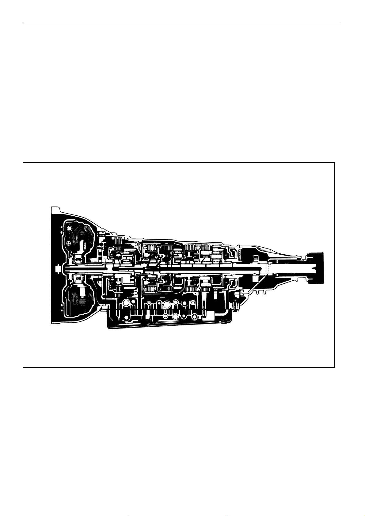
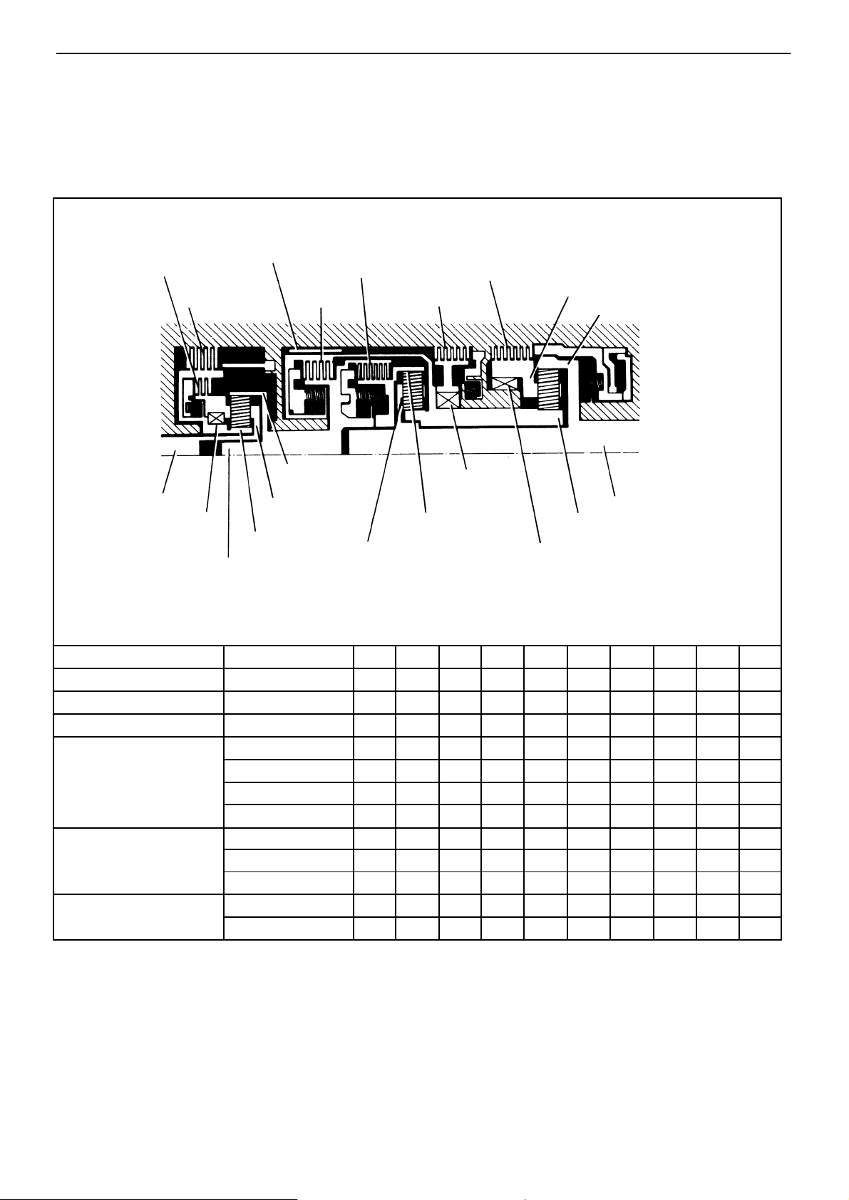
Sectional View
(A340E)
AT4366
AT−4
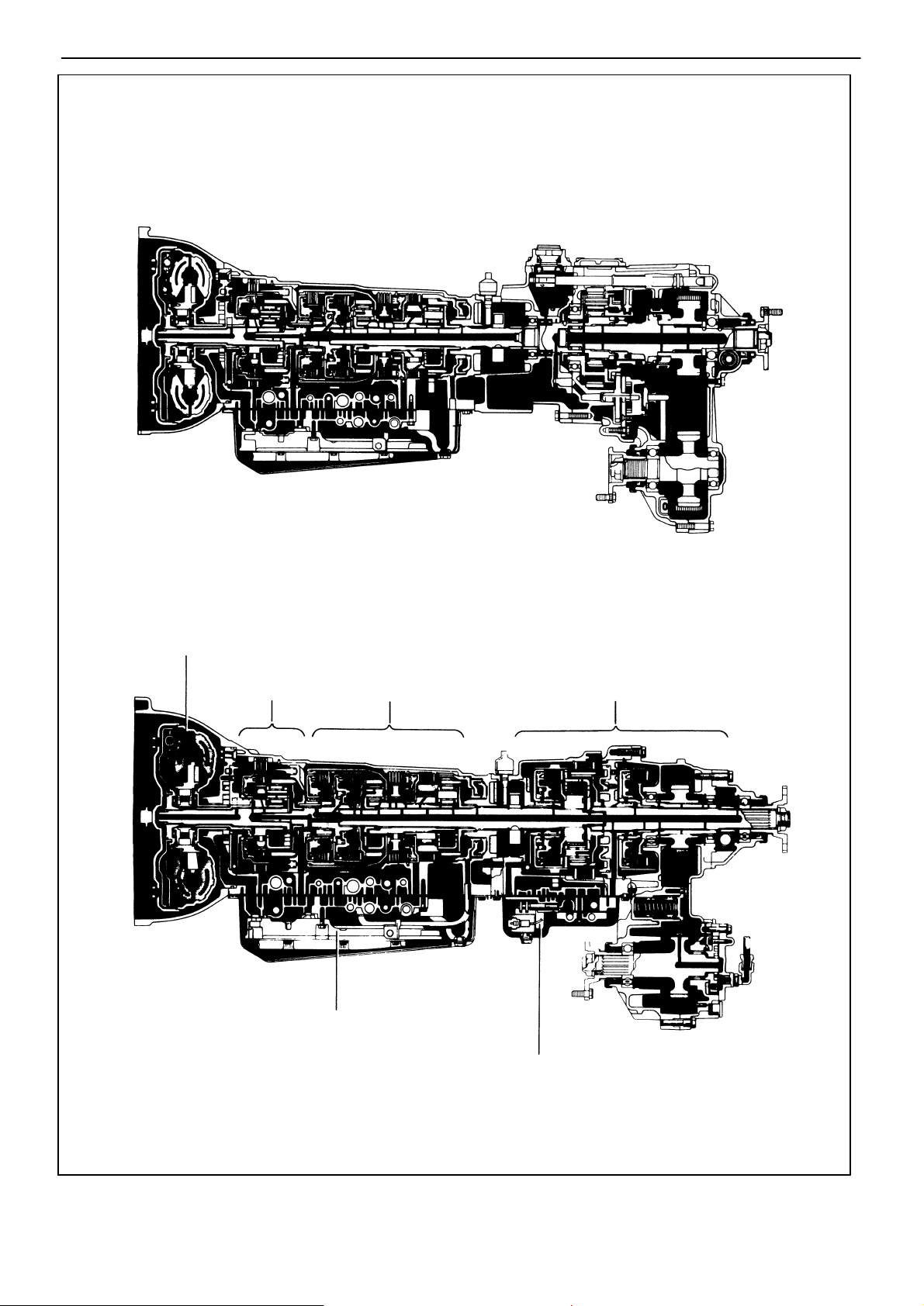
Sectional View
(A340F)
−AUTOMATIC TRANSMISSION Description
(A340H)
Torque Converter with
Lock−Up Clutch
O/D Planetary
Gear Unit
Transmission Hydraulic
Control Unit
3−Speed Planetary
Gear Unit
2−Speed Transfer
Transfer Hydraulic
Control Unit
AT5744
AT5068
General Specifications
−AUTOMATIC TRANSMISSION Description
AT−5
Type of Transmission
Type of Engine
Torque Converter
Gear Ratio
Plates (Disc/Plate)
Second Coast Brake Band Width
ATF
Stall Torque Ratio
Lock−Up Mechanism
1st Gear
2nd Gear
3rd Gear
O/D Gear
Reverse Gear
C
0
C
1
C
2
B22nd Brake
B
3
B0O/D Brake
Type
liters (US qts, Imp. qts)
O/D Direct Clutch
Forward Clutch
Direct Clutch
1st & Reverse Brake
Capacity
mm (in.)
Total
Drain and Refill
A340E
7M−GE, 7M−GTE, 3VZ−E
Truck : C & C 2.0 : 1 Others 2.1 : 1
Equipped
2.804
1.531
1.000
0.705
2.393
2/2
5/5
4/4
5/5
6/6
4/3
40 (1.57)
ATF DEXRONR II
7.2 (7.6, 6.3)
1.6 (1.7, 1.4)
AT−6
General Specifications (Cont’d)
−AUTOMATIC TRANSMISSION Description
Type of Transmission
Type of Engine
Torque Converter
Gear Ratio
Plates (Disc/Plate)
Second Coast Brake Band Width
ATF
Stall Torque Ratio
Lock−Up Mechanism
1st Gear
2nd Gear
3rd Gear
O/D Gear
Reverse Gear
C
0
C
1
C2Direct Clutch
B22nd Brake
B31st & Reverse Brake
B0O/D Brake
Type ATF DEXRONR II
O/D Direct Clutch
Forward Clutch
Capacity
liters
(US qts, Imp. qts)
A340F
22R−E
2.3 : 1
Equipped
2.804
1.531
1.000
0.705
2.393
2/2
5/5
4/4
5/5
6/6
4/3
mm (in.)
Total 7.6 (8.0, 6.7)
Drain and Refill
40 (1.57)
1.6 (1.7, 1.4)
General Specifications (Cont’d)
−AUTOMATIC TRANSMISSION Description
AT−7
Type of Transmission
Type of Engine
Torque Converter
Transmission
Gear Ratio
Transfer
Number of
Discs and
Plates
(Disc
/Plate)
Transmission
Transfer
Second Coast Brake Band Width
ATF
A340H
3VZ−E
Stall Torque Ratio
2.1 : 1
Lock−Up Mechanism Equipped
1st Gear 2.804
2nd Gear 1.531
3rd Gear
1.000
O/D Gear 0.705
Reverse Gear
High (H2, H4)
Low (L4)
Forward Clutch 4/4
C
1
Direct Clutch
C
2
O/D Direct Clutch 1/1
C
0
2nd Brake
B
2
1st & Reverse Brake
B
3
O/D Brake
B
0
Transfer Direct Clutch
C
3
C4Front Drive Clutch
Low Speed Brake
B
4
mm (in.)
Type
Transmission: 10.3 (10.9, 9.1),
Transfer: 1.1 (1.2, 1.0)
Transmission: 4.5 (4.8, 4.0),
Transfer: 0.8 (0.8, 0.7)
Capacity liter
(US qts, Imp. qts)
Total
Drain & Refill
2.393
1.000
2.659
3/3
4/4
5/5
3/2
6/6
6/6
7/6
40 (1.57)
ATF DEXRONR II
AT−8
OPERATION
Mechanical Operation
OPERATING CONDITIONS
(A340E, A340F)
−AUTOMATIC TRANSMISSION Operation
O/D Direct
CIutch (C0)
O/D Input Shaft
O/D One−Way
Clutch (F
Shift lever position
P
R
N Neutral
D
2
L
2nd Coast Brake (B1)
O/D Brake (B
)
0
Input Shaft
Forward Clutch (C1)
Direct
0
)
Clutch (C
)
2
2nd Brake (B
O/D Planetary
Ring Gear
O/D Planetary
Carrier
O/D Planetary
Sun Gear
Front Planetary
Front Planetary
Ring Gear
Carrier
Gear position
Parking
Reverse f
1st
2nd
3rd
O/D
1st
2nd
3rd ff
1st
*2nd
C
0
f
f
ff
f
f
ff
f
ff
ff
1st & Reverse
Brake (B
)
2
)
3
Rear Planetary Carrier
Rear Planetary Ring Gear
No. 1 One−Way
Clutch (F
)
1
Output Shaft
Front & Rear Planetary
Sun Gear
No. 2 One−Way
Clutch (F
C
C
1
f
ff
ff
ff
f
B
2
f
0
ff
)
2
B
ff
B
1
2
f
f
f
f
f ..... Operating
B
3
f
f
AT2157
F
f
f
f
f
ff
ff
f
f
ff
F
0
F
1
2
f
f
f
* Down−shift only in the L range and 2nd gear − no up−shift.
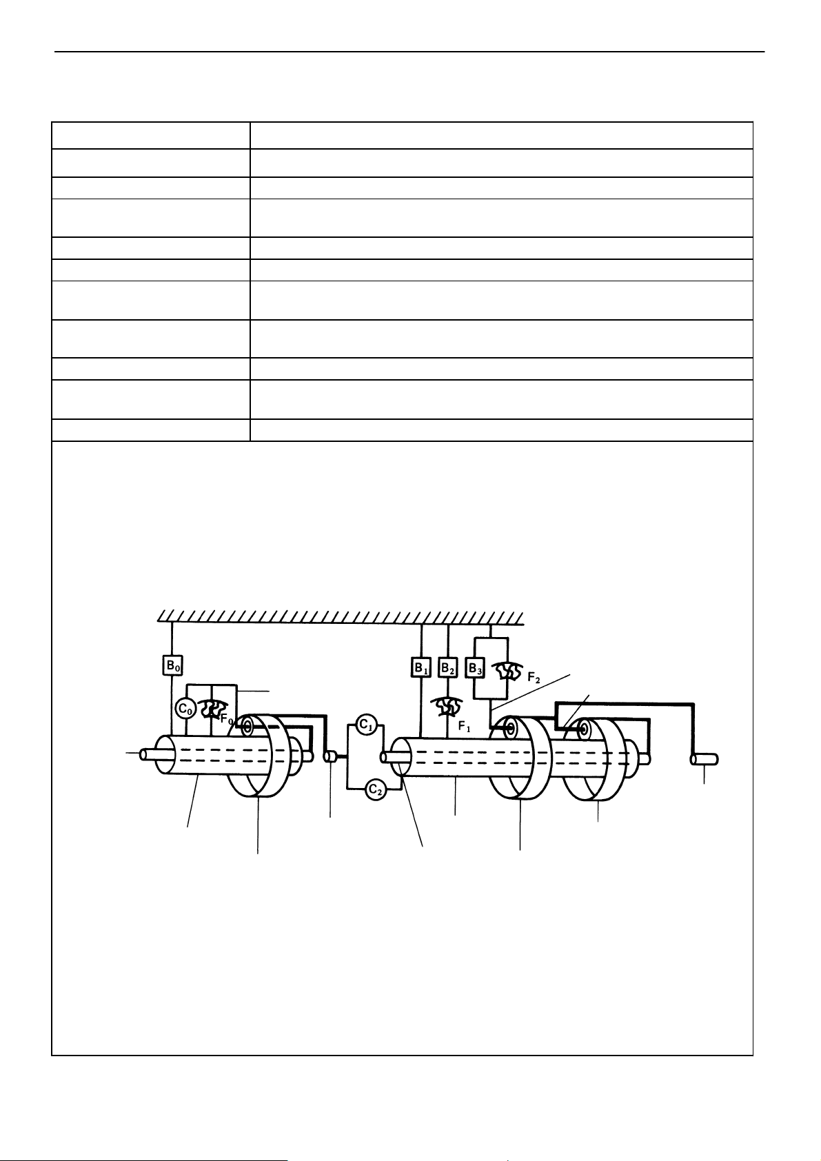
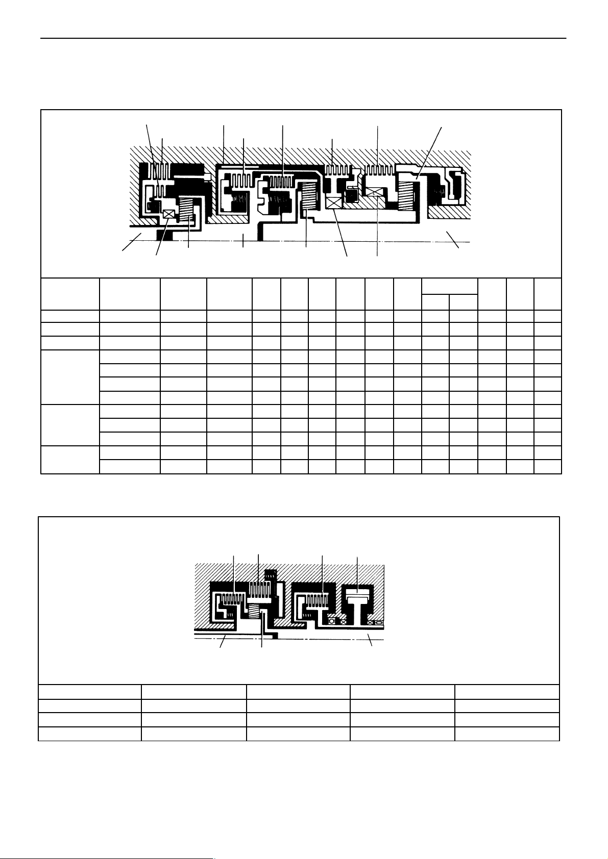
FUNCTION OF COMPONENTS
(A340E, A340F)
−AUTOMATIC TRANSMISSION Operation
AT−9
NOMENCLATURE
O/D Direct Clutch (C0)
O/D Brake (B
O/D One−Way Clutch (F
Forward Clutch (C1)
Direct Clutch (C2) Connects input shaft and front & rear planetary sun gear
2nd Coast Brake (B1)
2nd Brake (B2)
1st & Reverse Brake (B3)
No. 1 One−Way Clutch (F1)
No. 2 One−Way Clutch (F2)
) Prevents overdrive sun gear from turning either clockwise or counterclockwise
0
0)
Connects overdrive sun gear and overdrive carrier
When transmission is being driven by engine, connects overdrive sun gear and overdrive carrier
Connects input shaft and front planetary ring gear
Prevents front & rear planetary sun gear from turning either clockwise or counterclockwise
Prevents outer race of F1 from turning either clockwise or counterclockwise, thus preventing
front & rear planetary sun gear from turning counterclockwise
Prevents rear planetary carrier from turning either clockwise or counterclockwise
When B2 is operating, prevents front & rear planetary sun gear from turning counterclockwise
Prevents rear planetary carrier from turning counterclockwise
OPERATION
O/D Input
Shaft
O/D Sun Gear
O/D Planetary Ring Gear
O/D Planetary Carrier
Input Shaft
Sun Gear
Intermediate
Shaft
Front Planetary Carrier
Rear Planetary Carrier
Output Shaft
Rear Planetary Ring Gear
Front Planetary
Ring Gear
AT3282
AT−10
−AUTOMATIC TRANSMISSION Operation
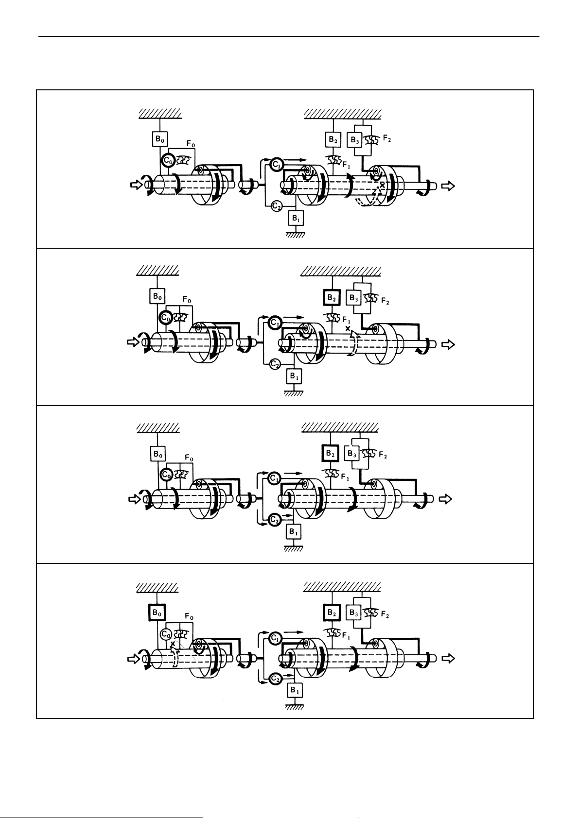
FUNCTION OF COMPONENTS (Cont’d)
The conditions of operation for each gear position are shown in the following illustrations:
D or 2 Range 1st Gear
D Range 2nd Gear
D or 2 Range 3rd Gear
AT6675
AT6676
D Range O/D
AT6677
AT6678
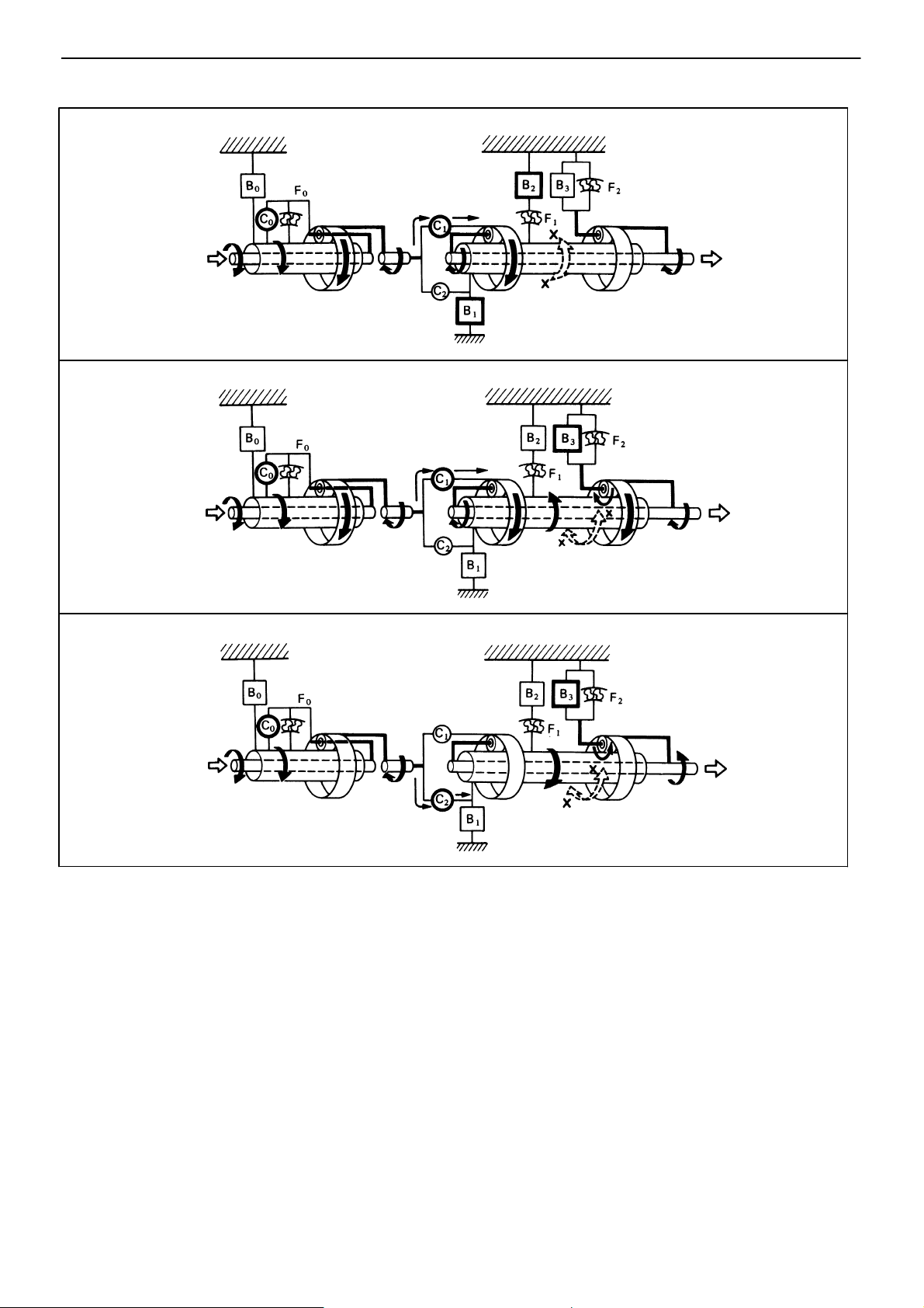
FUNCTION OF COMPONENTS (Cont’d)
2 or L Range 2nd Gear
L Range 1st Gear
−AUTOMATIC TRANSMISSION Operation
AT−11
AT6679
R Range Reverse Gear
AT6680
AT6681
AT−12
−AUTOMATIC TRANSMISSION Operation
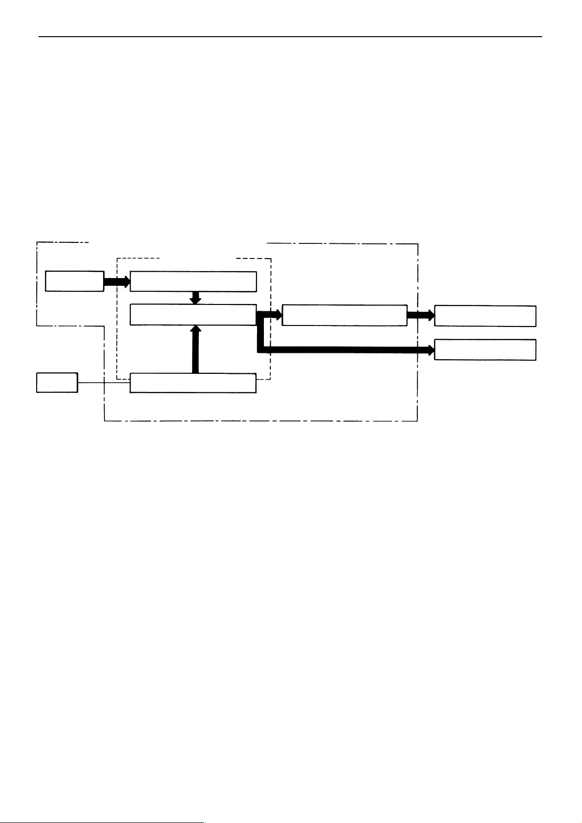
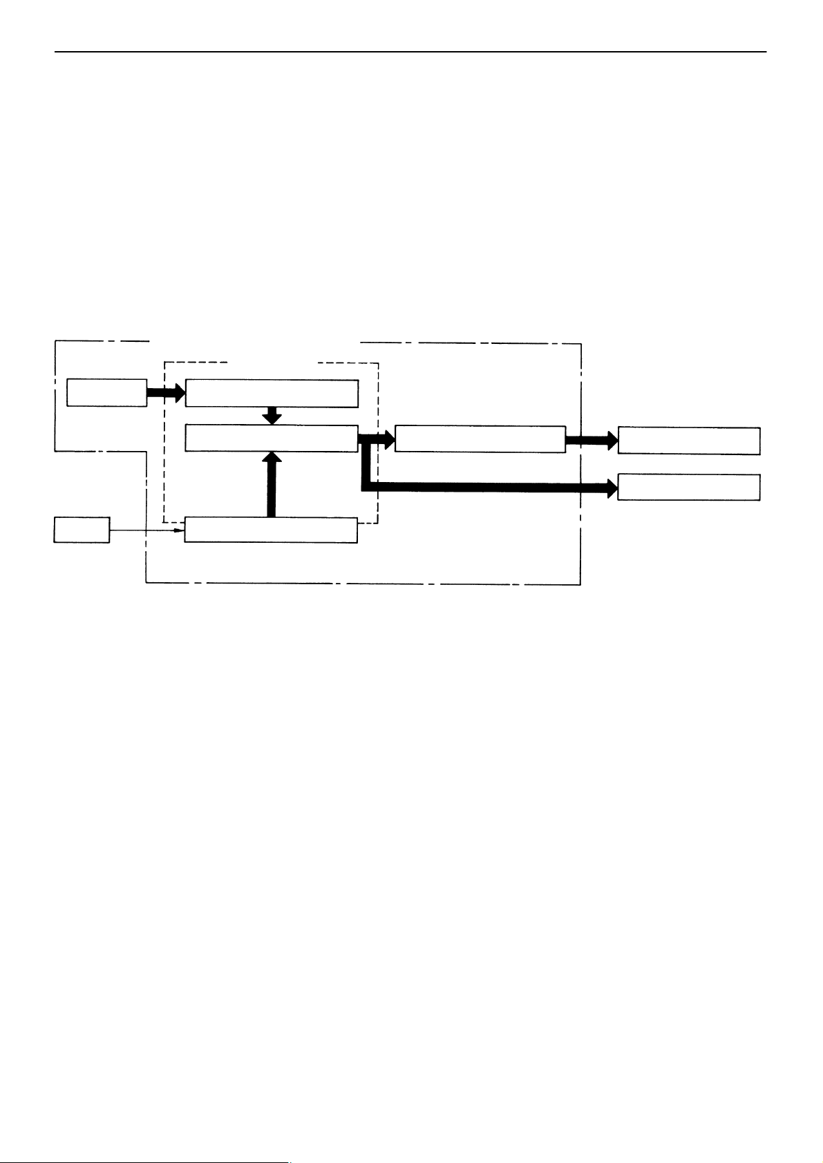
HYDRAULIC CONTROL SYSTEM
(A340E, A340F)
The hydraulic control system is composed of the oil pump, the valve body, the solenoid valves, and the
clutches and brakes, as well as the fluid passages which connect all of these components. Based on the
hydraulic pressure created by the oil pump, the hydraulic control system governs the hydraulic pressure
acting on the torque converter, clutches and brakes in accordance with the vehicle driving conditions.
There are three solenoid valves on the valve body. These solenoid valves are turned on and off by signals from the ECU to operate the shift valves. These shift valves then switch the fluid passages so that
fluid goes to the torque converter and planetary gear units.
(Except for the solenoid valves, the hydraulic control system of the ECT is basically the same as that of
the fully hydraulic controlled automatic transmission.)
HYDRAULIC CONTROL SYSTEM
VALVE BODY
OIL PUMP
ECU
S LINE PRESSURE
Hydr. pressure control
Fluid passage switching
SOLENOID VALVES
Line pressure is the most basic and important pressure used in the automatic transmission,
because it is used to operate all of the clutches and brakes in the transmission.
If the primary regulator valve does not operate correctly, line pressure will be either too high or
too low. Line pressure that is too high will lead to shifting shock and consequent engine power
loss due to the greater effort required of the oil pump; line pressure that is too low will cause
slippage of clutches and brakes, which will, in extreme cases, prevent the vehicle from moving. Therefore, if either of these problems are noted, the line pressure should be measured to
see if it is within standard.
S THROTTLE PRESSURE
Throttle pressure is always kept in accordance with the opening angle of the engine throttle
valve.
This throttle pressure acts on the primary regulator valve and, accordingly, line pressure is
regulated in response to the throttle valve opening.
In the fully hydraulic controlled automatic transmission, throttle pressure is used for regulating
line pressure and as signal pressure for up−shift and down−shift of the transmission. In the
ECT, however, throttle pressure is used only for regulating line pressure. Consequently, improper adjustment of the transmission throttle cable may result in a line pressure that is too
high or too low. This, in turn, will lead to shifting shock or clutch and brake slippage.
CLUTCHES & BRAKES
Planetary gear sets
Torque Converter
−AUTOMATIC TRANSMISSION Operation
AT−13
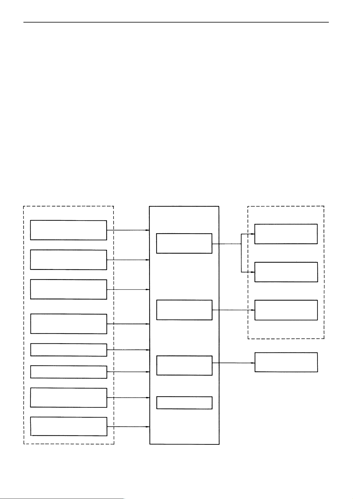
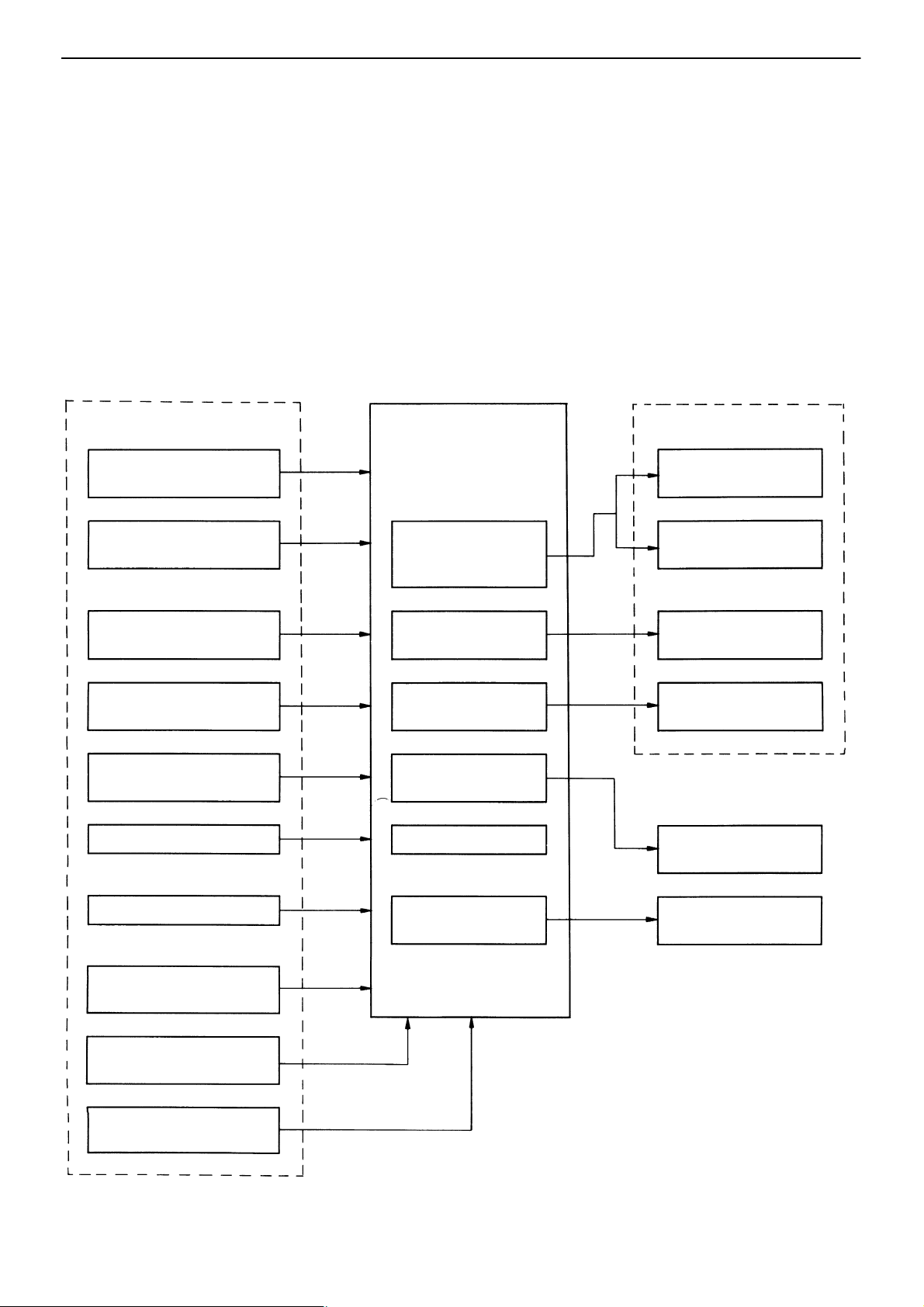
ELECTRONIC CONTROL SYSTEM
(A340E, A340F)
The electronic control system, which controls the shift points and the operation of the lock−up clutch, is
composed of the following three parts:
1. Sensors
These sensors sense the vehicle speed, throttle opening and other conditions and send these
data to the ECU in the form of electrical signals.
2. ECU
The ECU determines the shift and lock−up timing based upon the signals from sensors, and
controls the solenoid valves of the hydraulic control unit accordingly.
3. Actuators
These are three solenoid valves that control hydraulic pressure acting on the hydraulic valves
to control shifting and lock−up timing.
SENSORS
DRIVING PATTERN
SELECTOR
NEUTRAL START
SWITCH
THROTTLE POSITION
SENSOR
VEHICLE SPEED
SENSOR
BRAKE LIGHT SWITCH
O/D MAIN SWITCH
ECU
Control of shift
timing
Control of lock−
up timing
Self−diagnostic
system
ACTUATORS
NO. 1
SOLENOID VALVE
NO. 2
SOLENOID VALVE
LOCK−UP
SOLENOID VALVE
O/D OFF
INDICATOR LIGHT
CRUISE CONTROL
ECU
WATER TEMPERATURE SENSOR
Back−up system
AT−14
OPERATING CONDITIONS
(A340H)
1. Transmission
−AUTOMATIC TRANSMISSION Operation
O/D Input
Shaft
Range (i.e.,
Shift Lever
Position)
P Parking
R
N
D
2
L
C
0
B
0
O/D Planetary
F
0
Gear Unit
Gear
Reverse
Neutral ON
1st ON
2nd
3rd OFF
O/D
1st ON
2nd
3rd
1st
* 2nd
No. 1
Solenoid
Valve
ON
ON
ON
OFF
ON ON F
OFF
ON
ON
B
1
C
2
Input
Shaft
No. 2
Solenoid
Valve
OFF F
OFF F
OFF
OFF F
ON
ON FF
OFF
OFF F
ON F
OFF FF
ON
C
1
Front Planetary
Gear Unit
C
C
0
F
F
F
F
FF
F
F
FF
F
F
B
2
C
1
2
F
F
* Down−shift only in the L range and 2nd gear − no up−shift.
2. Transfer
B
F
F
1
B
B
0
F
F
F
Rear Planetary Gear Unit
3
2
B
1
2
I.P. O.P.
FF
F
F
F
F
F
FF
F
Output Shaft
B
3
AT2157
F
F
0
F
F
F
F
F
F
F
F
F
F
1
2
F
F
F
F
F
F
I.P. ....... Inner Piston
O.P. ..... Outer Piston
Transfer gear position
H2 OFF
H4 OFF
L4 ON
B
C
4
3
C
4
Transmission Output Shaft Transfer Planetary Gear Unit
No. 4 solenoid valve
C
3
F
F
Chain
Transfer Rear Output Shaft
C
4
F
F
ND0045
B
4
F
FUNCTION OF COMPONENTS
(A340H)
1. Transmission
−AUTOMATIC TRANSMISSION Operation
AT−15
Component
C
Forward Clutch
1
C
Direct Clutch
2
C
O/D Direct Clutch
0
2nd Coast Brake Prevents front & rear planetary sun gear from turning either clockwise or counterclockwise.
B
1
B22nd Brake
B31st & Reverse Brake Prevents rear planetary carrier from turning either clockwise or counterclockwise.
B0O/D Brake Prevents overdrive sun gear from turning either clockwise or counterclockwise.
F1No. 1 One−Way Clutch
F
No. 2 One−Way Clutch Prevents rear planetary carrier from turning counterclockwise.
2
F0O/D One−Way Clutch
Planetary Gears
Connects input shaft and front planetary ring gear.
Connects input shaft and front & rear planetary sun gear.
Connects overdrive sun gear and overdrive planetary carrier.
Prevents outer race of F1 from turning either clockwise or counterclockwise thus
preventing the front & rear planetary sun gear from turning counterclockwise.
When B2 is operating, this clutch prevents the front & rear planetary sun gear from turning
counterclockwise.
When the transmission is being driven by the engine, this clutch connects the overdrive sun
gear and overdrive planetary carrier.
These gears change the route through which driving force is transmitted in accordance
with the operation of each clutch and brake in order to increase or reduce the input and
output speed.
Function
IN
O/D Input
Shaft
O/D Carrier
O/D Sun Gear
O/D Pinion
O/D Ring Gear
Input Shaft
Front Carrier
Front Ring Gear
Front
Pinion
Front & Rear Sun Gear
Rear Carrier
Rear Pinion
OUT
Output Shaft
Rear Ring Gear
AT5440

AT−16
−AUTOMATIC TRANSMISSION Operation
FUNCTION OF COMPONENTS (Cont’d)
The conditions of operation for each gear position are shown in the following illustrations:
D or 2 Range 1st Gear
C
0
D Range 2nd Gear
C
0
2 or L Range 2nd Gear
B
2
C
C
1
AT5854
0
C
1
B
1
AT5854
L Range 1st Gear
B
2
C
C
1
0
C
1
B
3
D or 2 Range 3rd Gear
C
0
D Range O/D
B
0
AT5854
AT5854
R Range Reverse Gear
B
2
C
C
1
C
2
AT5854
B
2
C
1
C
2
0
C
2
B
3
AT5854
AT5854
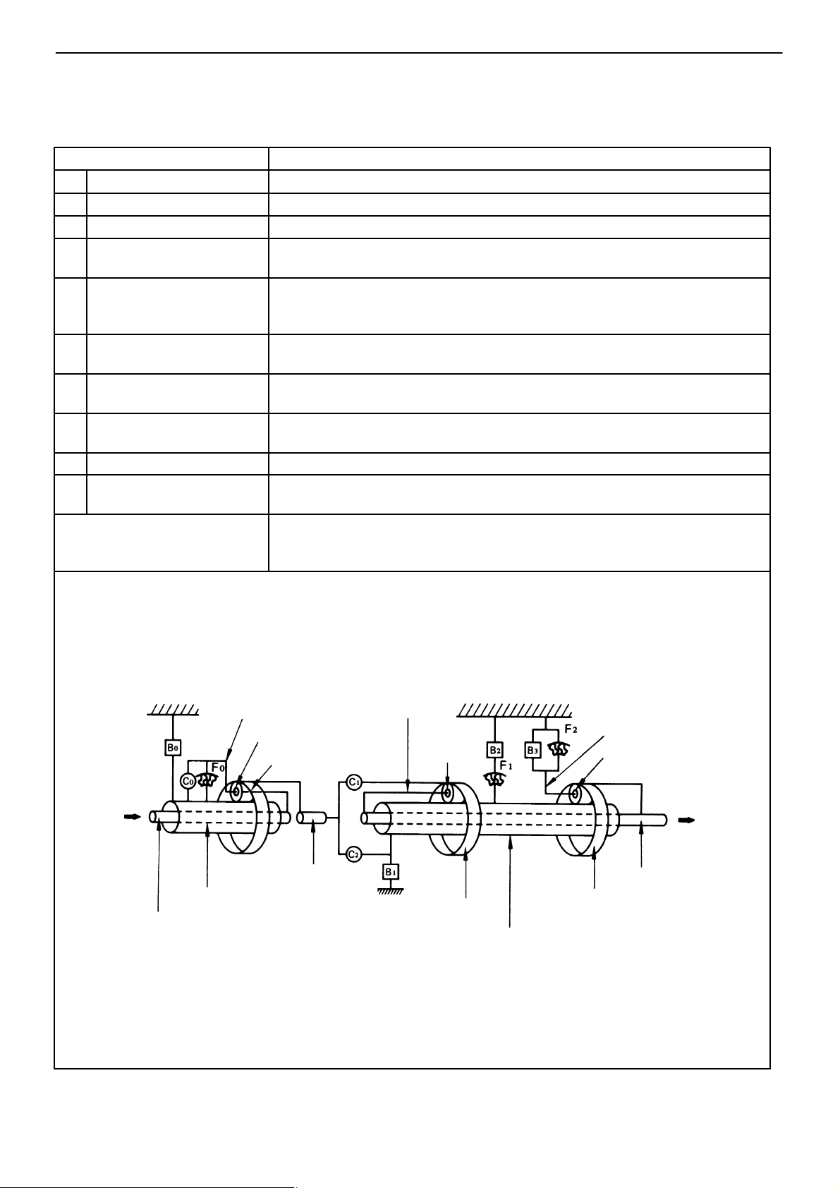
FUNCTION OF COMPONENTS (Cont’d)
2. Transfer
−AUTOMATIC TRANSMISSION Operation
AT−17
Component
C3Forward Clutch
C
Direct Clutch
4
O/D Direct Clutch
B
4
IN
Transmission
Output Shaft
Function
Connects transmission output shaft and transfer pinion gear.
Connects transfer rear output shaft and front drive gear.
Prevents transfer ring gear from turning either clockwise or counterclockwise.
Transfer Rear Output Shaft
OUT
Ring Gear
Front Drive Gear
Chain
OUT
Transfer Front
Output Shaft
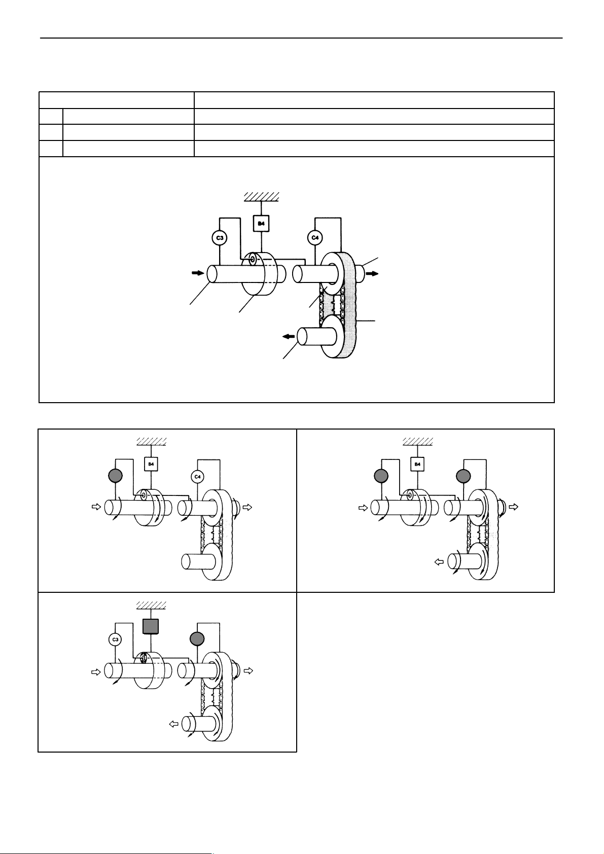
The conditions of operation for each gear position are shown in the following illustrations:
H2 Range
L4 Range
C
3
ND0047
B4
C
4
H4 Range
C
3
C
4
ND0047
ND0047
ND0047
AT−18
−AUTOMATIC TRANSMISSION Operation
HYDRAULIC CONTROL SYSTEM
(A340H)
1. Transmission
The hydraulic control system is composed of the oil pump, the valve body, the solenoid valves, and the
clutches and brakes, as well as the fluid passages which connect all of these components. Based on the
hydraulic pressure created by the oil pump, the hydraulic control system governs the hydraulic pressure
acting on the torque converter, clutches and brakes in accordance with the vehicle driving conditions.
There are three solenoid valves on the valve body. These solenoid valves are turned on and off by signals from the Engine & ECT ECU to operate the shift valves. These shift valves then switch the fluid
passages so that fluid goes to the torque converter and planetary gear units.
HYDRAULIC CONTROL SYSTEM
VALVE BODY
OIL PUMP
ECU
Hydr. pressure control
Fluid passage switching
SOLENOID VALVES
CLUTCHES & BRAKES
2. Transfer
The hydraulic control system consists of a valve body, No. 4 solenoid valve, a brake (B
clutches (C
, C4) and passages that connect these elements. It hydraulically controls the planetary gear
3
unit either manually, or automatically by the Engine & ECT ECU.
Planetary gear sets
Torque converter
) and two
4
−AUTOMATIC TRANSMISSION Operation
AT−19
ELECTRONIC CONTROL SYSTEM
(A340H)
The electronic control system, which controls the transmission and transfer shift timing and the operation
of the lock−up clutch, is composed of the following three parts:
1. Sensors
These sensors sense the vehicle speed, throttle opening and other conditions and send these data
to the Engine & ECT ECU in the form of electrical signals.
2. Engine & ECT ECU
The Engine & ECT ECU determines the transmission and transfer shift timing and lock−up timing
based upon the signals from sensors, and controls the solenoid valves of the hydraulic control unit
accordingly.
3. Actuators
These are four solenoid valves that control hydraulic pressure acting on the hydraulic valves to
control shifting and lock−up timing.
SENSORS
DRIVING PATTERN
SELECTOR
NEUTRAL START
SWITCH
TRANSFER SHIFT
POSITION SWITCH
THROTTLE POSITION
SENSOR
VEHICLE SPEED
SENSOR
BRAKE LIGHT SWITCH
Engine & ECT ECU
Control of
transmission
shift timing
Control of
lock−up timing
Control of transfer
shift timing
Self−diagnostic
system
Back−up system O/D OFF INDICATOR
ACTUATORS
NO. 1
SOLENOID VALVE
NO. 2 SOLENOID
VALVE
LOCK UP SOLENOID
VALVE
NO. 4
SOLENOID VALVE
LIGHT
O/D MAIN SWITCH
CRUISE CONTROL
ECU
WATER TEMPERATURE
SENSOR
FLUID TEMPERATURE
SENSOR
Fluid temperature
warning system
A.T. OIL TEMP.
WARNING LIGHT
AT−20
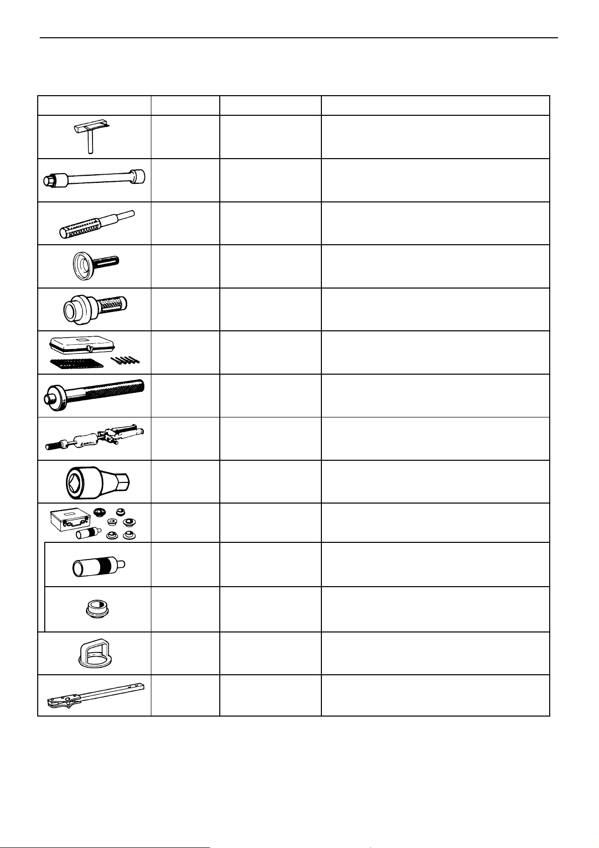
PREPARATION
SST (SPECIAL SERVICE TOOLS)
−AUTOMATIC TRANSMISSION Preparation
Illustration
Part No.
09032−00100
09043−38100
09201−60011
09223−15010
09223−22010
09240−00020
09304−12012
Part Name
Oil Pan Seal
Cutter
Hexagon 10 mm
Wrench
Valve Guide Bushing
Remover & Replacer
Crankshaft Front
Oil Seal Replacer
Crankshaft Front
Oil Seal Replacer
Wire Gauge Set
Input Shaft Front
Bearing Replacer
Note
Transfer (A340F)
Transfer (A340F)
Transfer (A340F)
Transfer (A340F)
Transfer (A340F)
09308−00010
09313−30021
09316−60010
(09316−00010)
(09316 − 00070)
09320−89010
09330−00021
Oil Seal Puller
Detent Ball Plug
Socket
Transmission &
Transfer Bearing
Replacer
Replacer ”A”
Replacer ”F” Transfer (A340F)
Transfer Clutch
Spring Compressor
Companion Flange
Holding Tool
Transfer (A340F)
Transfer (A340F)
Transfer (A340F)
A340H
A340H

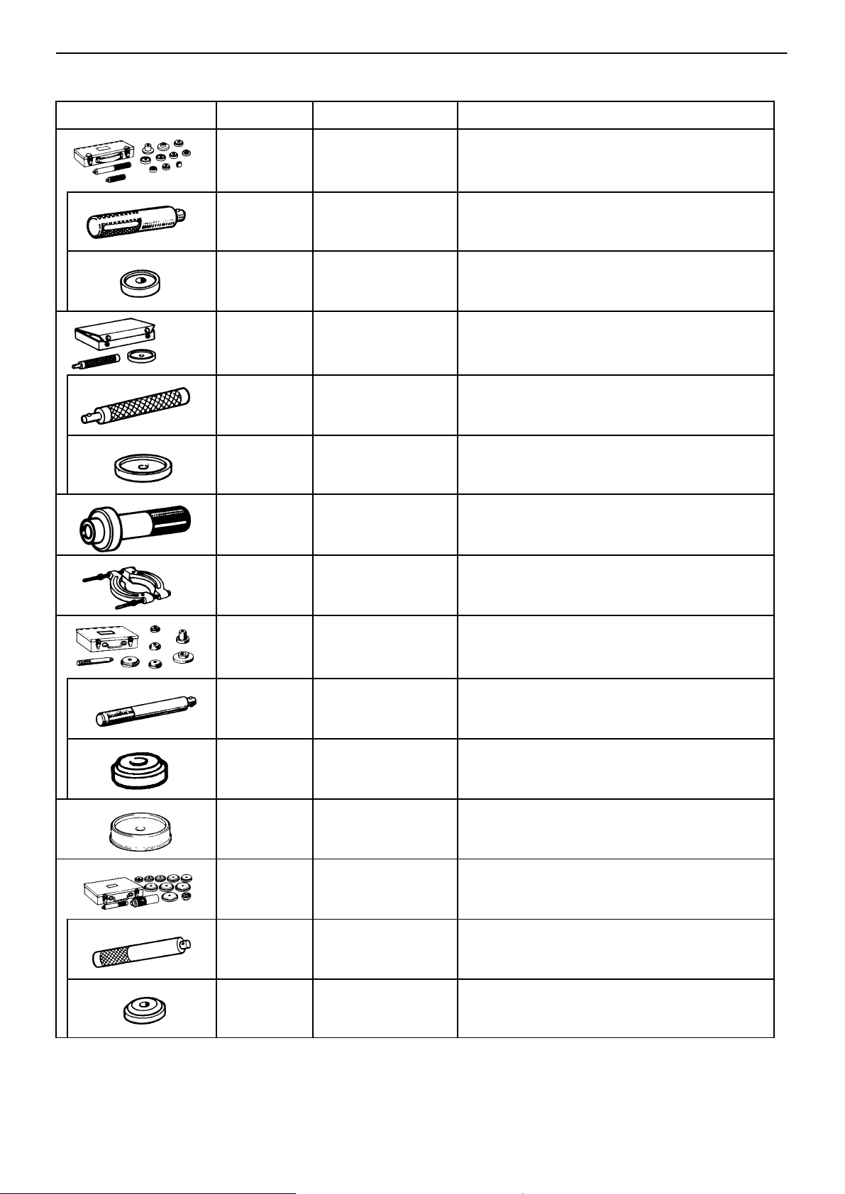
SST (SPECIAL SERVICE TOOLS) (Cont’d)
−AUTOMATIC TRANSMISSION Preparation
AT−21
Illustration
Part No.
09350−30020
(09350−06120)
(09350−07020)
(09350−07030)
(09350−07040)
(09350−07050)
(09350−07060)
Part Name
TOYOTA Automatic
Transmission Tool
Set
No. 2 Measure
Terminal
Oil Pump Puller
No. 1 Piston Spring
Compressor
No. 2 Piston Spring
Compressor
No. 3 Piston Spring
Compressor
No. 1 Snap Ring
Expander
Note
A340E
(09350−07070)
(09350−07080)
(09350−07090)
(09350−07110)
(09351−32140)
09350−36010
(09350−06090)
No. 2 Snap Ring
Expander
Brake Reaction Sleeve
Puller
Brake No. 1 Piston
Puller
Oil Seal Replacer
Oil Seal Replacer
TOYOTA Automatic
Transmission Tool
Set
Plate
A340E
09515−30010
Rear Wheel Bearing
Replacer
Transfer (A340F)
AT−22
SST (SPECIAL SERVICE TOOLS) (Cont’d)
−AUTOMATIC TRANSMISSION Preparation
Illustration
Part No.
09550−10012
(09252−10010)
(09557−10010)
09550−22011
(09550−00020)
(09550−00031)
09554−30011
Part Name
Replaces Set ”B”
No. 1 Replacer Handle Transfer (A340F)
Differential Drive
Pinion Front Bearing
Replacer
Rear Axle Bearing
& Differential Tool
Set
Handle Transfer (A340F)
(Replacer Transfer (A340F)
Differential Oil
Seal Replacer
Transfer (A340F)
Transfer (A340F)
Transfer (A340F)
Transfer (A340F)
Note
09555−55010
09608−12010
(09608−00020)
(09608−00040)
09608−32010
09608−35014
(09608−06020)
Differential Drive
Pinion Bearing
Replacer
Front Hub & Drive
Pinion Bearing
Replacer Set
Remover & Replacer
Handle
Front Hub Outer
Bearing Cup Replacer
Steering Knuckle Oil
Seal Replacer
Axle Hub &
Drive Pinion Bearing
Tool Set
Handle
Transfer (A340F)
Transfer (A340F)
Transfer (A340F)
Transfer (A340F)
A340H
A340H
A340H
(09608−06100)
Front Hub Outer
Replacer
A340H
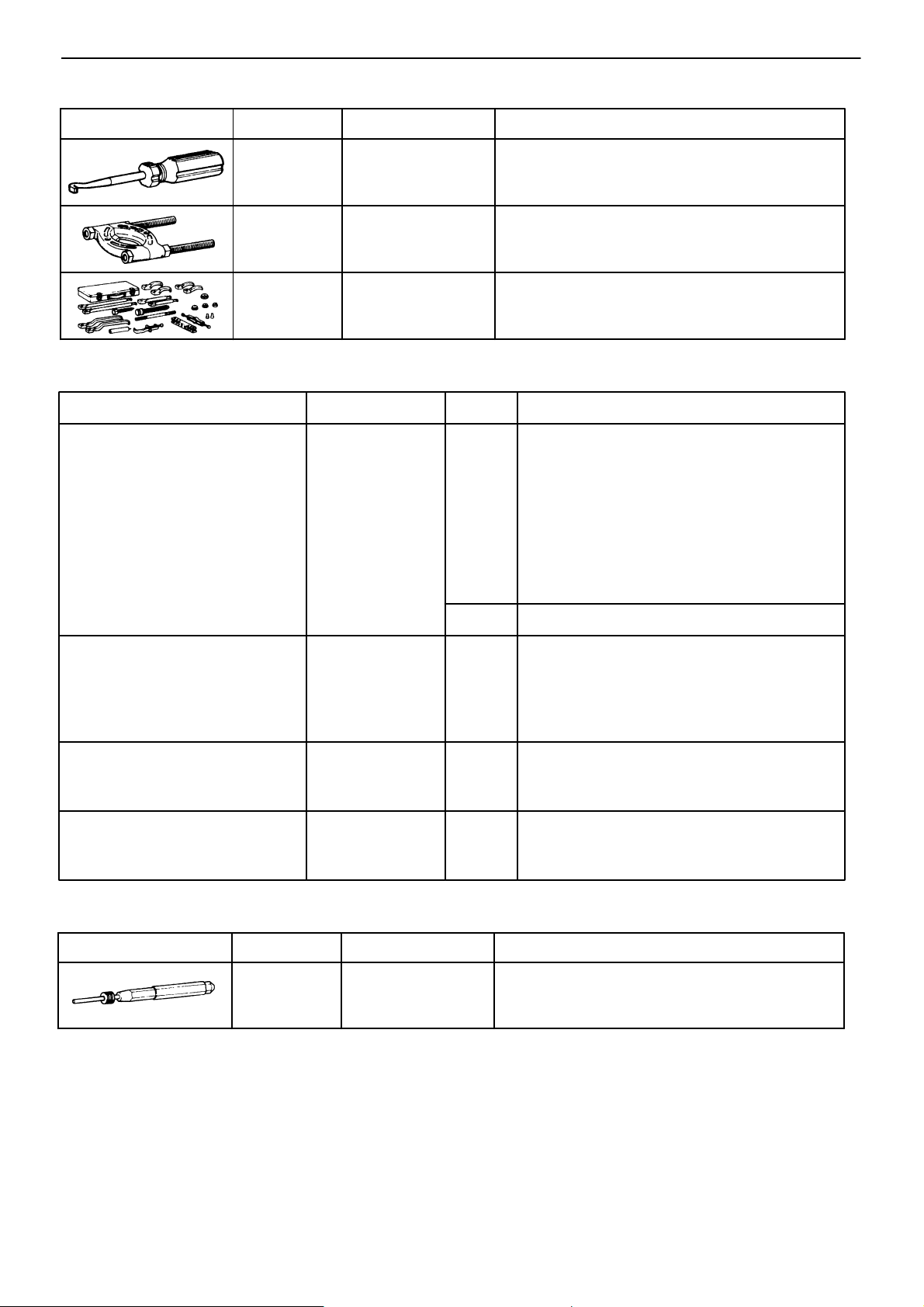
SST (SPECIAL SERVICE TOOLS) (Cont’d)
−AUTOMATIC TRANSMISSION Preparation
AT−23
Illustration
Part No. Part Name
09921−00010
09950−00020
09950−20017
Spring Tension Tool
Bearing Remover
Universal Puller
SSM (SPECIAL SERVICE MATERIALS)
Part Name
Seal packing 1281,
Three bond 1281 or equivalent
Part No. Sec. Use etc.
08826−00090
Transfer (A340F)
Transfer (A340F)
Transfer (A340F)
AT
Note
(A340E)
Oil pan
(A340H)
Transfer case
Transfer chain front case
Transfer chain rear case
Transfer oil pump
Transfer oil pan
Transmission oil pan
Adhesive 1324,
Three bond 1324 or equivalent
Adhesive 1344,
Three bond 1344,
Loctite 242 or equivalent
Adhesive 1131,
Three bond 1131,
Loctite 518 or equivalent
RECOMMENDED TOOLS
Illustration
Part No.
09031−00030
08833−00070
08833−00080
08833−00090
Part Name
Pin Punch
AT
AT
TF
TF
Rear companion flange
(A340H)
Transfer oil strainer set bolts
Transfer chain front case set bolts
Transfer chain oil receiver set bolts
Transfer oil pan set bolts
Straight screw plug
Extension housing set bolt
Front reatainer set bolt
(A340H)
Transfer extension housing
Note

AT−24
EQUIPMENT
−AUTOMATIC TRANSMISSION Preparation
Part Name
Feeler gauge
Vernier caliper with depth gauge
Dial indicator with magnetic base
Dial indicator
Straight edge
Torque wrench
Cylinder gauge
Note
Check major clearance.
Check length of second coast brake piston rod.
Check piston stroke and end play of the output shaft.
Check inside diameter of major bushing.
Check side clearance of oil pump.
Check inside diameter of the transmission case rear bushing.
−AUTOMATIC TRANSMISSION (A340E) Removal of Component Parts
AT−25
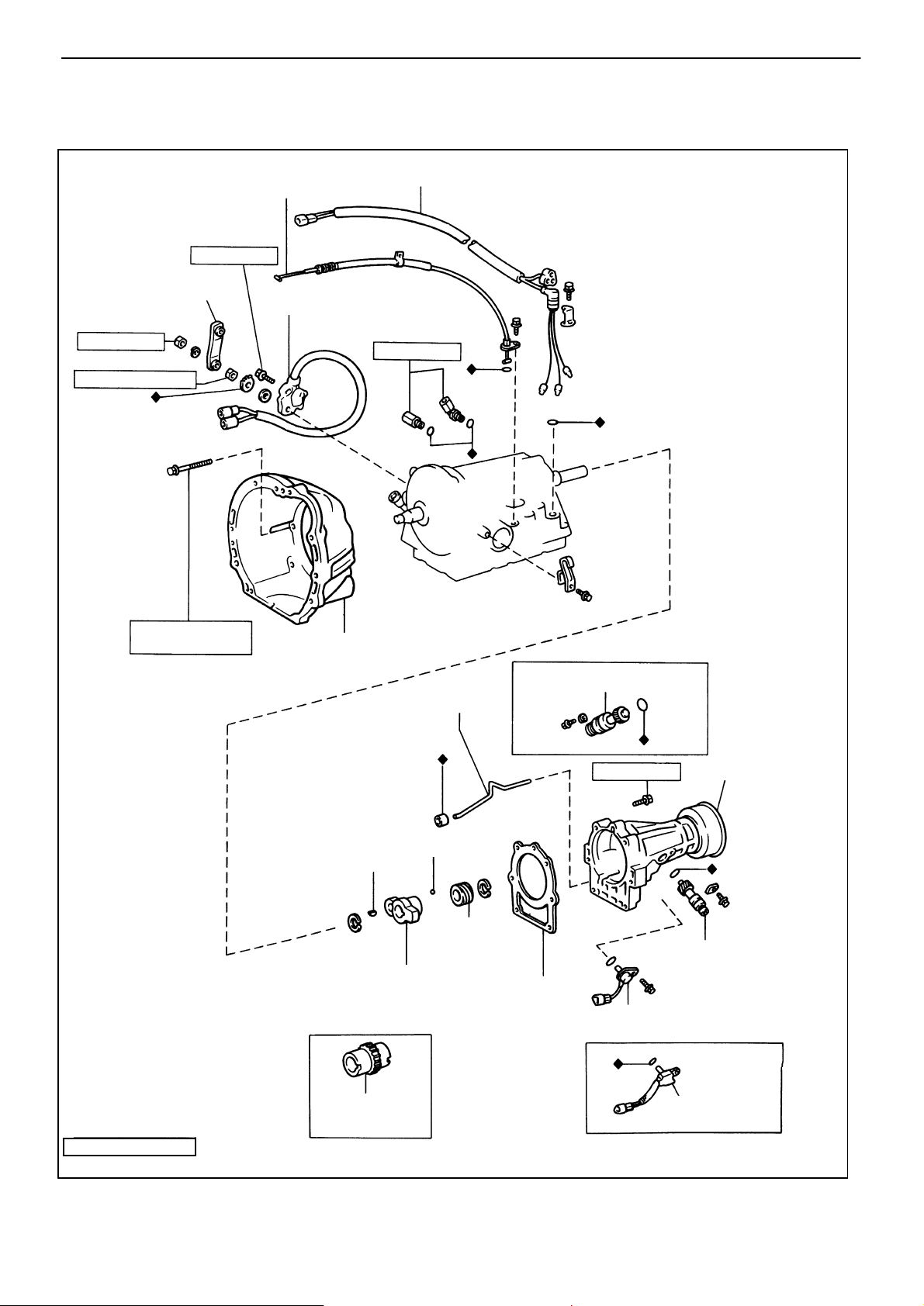
REMOVAL OF COMPONENT PARTS (A340E)
COMPONENTS (SUPRA and CRESSIDA)
Control Shaft Lever
160 (12, 16)
70 (61 in.−lb, 6.9)
Throttle Cable
Adjusting Bolt
130 (9, 13)
Neutral Start Switch
Solenoid Wire
Union
300 (22, 29)
10 mm 345 (25, 34)
12 mm 580 (42, 57)
Transmission Housing
Oil Apply Tube
Key
Sensor Rotor
Ball
Speedometer
Drive Gear
(w/o ABS)
(SUPRA)
♦ Gasket
Speedometer
Drive Gear
370 (27, 36)
Speed Sensor
(w/o ABS)
Extension Housing
Speedometer
Drive Gear
(CRESSIDA)
kg−cm (ft−lb, N−m)
♦ Non−reusable part
: Specified torque
Sensor Rotor
(w/ ABS)
Speed Sensor
(w/ ABS)
AT8370
AT−26
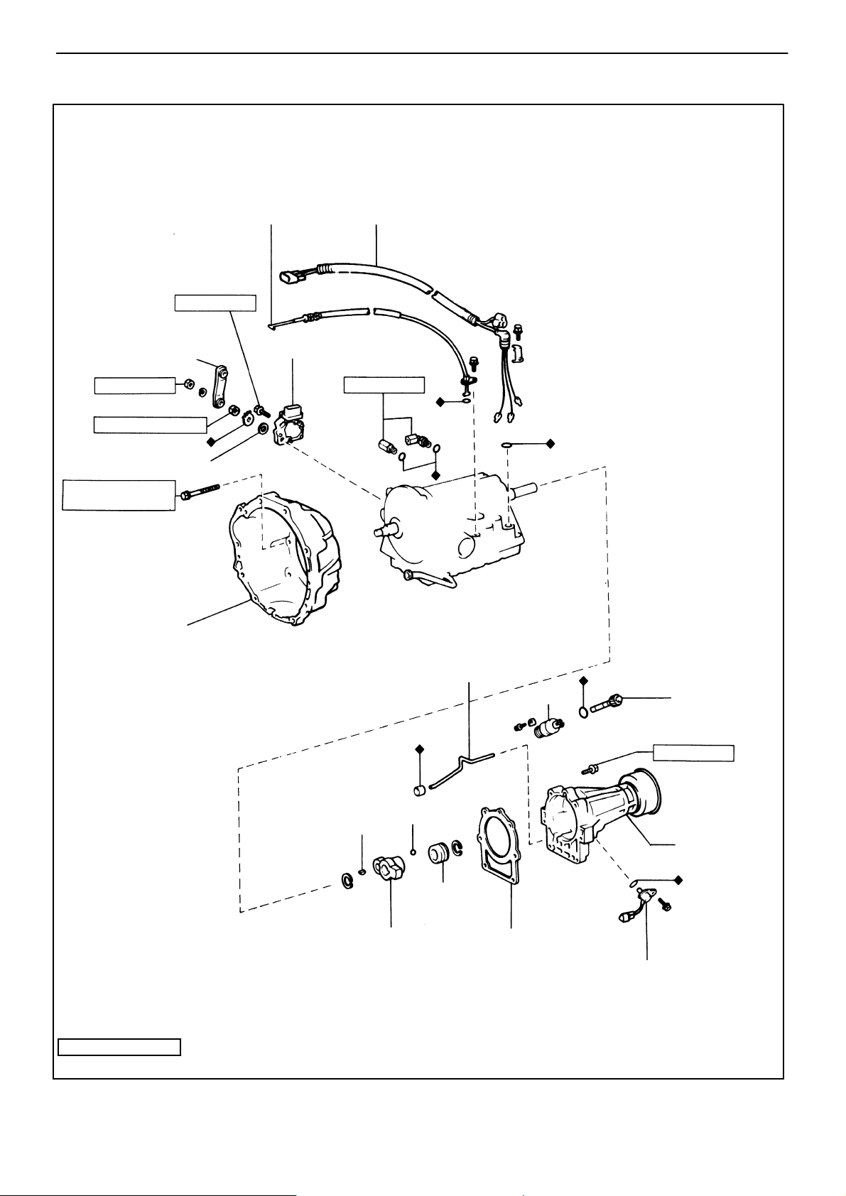
−AUTOMATIC TRANSMISSION (A340E) Removal of Component Parts
COMPONENTS (TRUCK and 4 RUNNER)
Throttle Cable
Adjusting Bolt
130 (9, 13)
Control Shaft Lever Neutral Start Switch
160 (12, 16)
70 (61 in.−lb, 6.9)
Grommet
10 mm 345 (25, 34)
12 mm 580 (42, 57)
Solenoid Wire
Union
300 (22, 29)
Transmission Housing
Key
Ball
Speedometer
Drive Gear
Sensor Rotor
Oil Apply Tube
♦ Gasket
Sleeve
Speedometer
Driven Gear
370 (270, 36)
Extension
Housing
Speed Sensor
kg−cm (ft−lb, N−m) : Specified torque
♦ Non−reusable part
AT4622
 Loading...