

Page 1

HIGH PERFORMANCE TRANSISTOR INVERTER
IGBT DIGITAL SERIES
TOSVERT-130G2+
OPERATION MANUAL
October, 1994
Part #34470
Page 2

IMPORTANT NOTICE
The instructions contained in this manual are not intended to cover all of the details
or variations in equipment, nor to provide for every possible contingency
to be met in connection with installation, operation, or maintenance. Should
additional information be desired or should particular problems arise which are not
covered sufficiently for the purchaser's purposes, the matter should be referred to
the local Toshiba sales office.
The contents of this instruction manual shall not become a part of or modify any
prior or existing agreement, commitment, or relationship. The sales contract
contains the entire obligation of Toshiba International Corporation's Inverter Division.
The warranty contained in the contract between the parties is the sole warranty of
Toshiba International Corporation's Inverter Division and any
statements contained herein do not create new warranties or modify the existing
warranty.
Toshiba International Corporation reserves the right, without prior notice, to update
information, make product changes, or to discontinue any product or service
identified in this publication.
TOSHIBA
Any electrical or mechanical modification to this equipment,
without prior written consent of Toshiba International
Corporation, will void all warranties and may void UL listing and/
or CSA certification.
AC ADJUSTABLE SPEED DRIVE
Please complete the Extended Warranty Card supplied with this inverter and return
it by prepaid mail to Toshiba. This activates the extended warranty. If additional information or technical assistance is required, call Toshiba's marketing department toll free
at (800) 231-1412 or write to: Toshiba International Corporation, 13131 W. Little York
Road, Houston, TX 77041-9990.
Please complete the following information for your records and to remain within this
equipment manual:
Model Number:
Serial Number:
Date of Installation:
Inspected By:
Reference Number:
i
Page 3

TOSHIBA
INTRODUCTION
Thank you for purchasing the TOSVERT-130G2+. This adjustable frequency solid state AC
drive features pulse width modulation, digital control, and user programmability. The very latest
microprocessor and insulated gate bipolar transistor technology is used. This, combined with
Toshiba's high performance software, gives unparalleled motor control and reliability.
It is the intent of this operation manual to provide a guide for safely installing, operating, and
maintaining the drive. This operation manual contains a section of general safety instructions
and is marked throughout with warning symbols. Read this operation manual thoroughly before
installing and operating this electrical equipment.
All safety warnings must be followed to ensure personal safety.
Follow all precautions to attain proper equipment performance and longevity.
We hope that you find this operation manual informative and easy to use. If additional information or technical assistance is needed, please call toll free (800) 231-1412 or write to: Toshiba International Corporation,
13131 W. Little York Road, Houston, TX 77041-9990.
Again, thank you for the purchase of this product.
TOSHIBA INTERNATIONAL CORPORATION
ii
Page 4
GENERAL SAFETY INSTRUCTIONS
Warnings in this manual appear in either of two ways:
1) Danger warnings - The danger warning symbol is an exclamation mark enclosed in a
triangle which precedes the 3/16" high letters spelling the word "DANGER". The
Danger warning symbol is used to indicate situations, locations, and conditions that
can cause serious injury or death:
DANGER
2) Caution warnings - The caution warning symbol is an exclamation mark enclosed in a
triangle which precedes the 3/16" high letters spelling the word "CAUTION". The
Caution warning symbol is used to indicate situations and conditions that can cause
operator injury and/or equipment damage:
CAUTION
TOSHIBA
Other warning symbols may appear along with the Danger and Caution symbol and are used to specify
special hazards. These warnings describe particular areas where special care and/or procedures are
required in order to prevent serious injury and possible death:
1) Electrical warnings - The electrical warning symbol is a lighting bolt mark enclosed in
a triangle. The Electrical warning symbol is used to indicate high voltage locations and
conditions that may cause serious injury or death if the proper precautions are not
observed:
2) Explosion warnings - The explosion warning symbol is an explosion mark enclosed in
a triangle. The Explosion warning symbol is used to indicate locations and conditions
where molten, exploding parts may cause serious injury or death if the proper
precautions are not observed:
iii
Page 5

TOSHIBA
CONTENTS
SECTION PAGE
Disclaimer ..........................................................................................................i
Introduction ......................................................................................................... ii
General Safety Instructions..............................................................................iii
Contents ...................................................................................................... iv-vi
1.0 Inspection/Storage/Disposal ......................................................................... 1-1
1.1 Inspection of the New Unit.......................................................................1-1
1.2 Storage ..................................................................................................... 1-1
1.3 Disposal .................................................................................................... 1-1
2.0 Safety In Installation and Operation............................................................. 2-1
2.1 Installation Precautions ........................................................................... 2-1
2.2 Operating Precautions ............................................................................ 2-2
2.3 Confirmation of Wiring ............................................................................ 2-3
2.4 Start-up and Test ..................................................................................... 2-3
2.5 Maintenance............................................................................................. 2-3
3.0 Standard Specifications.................................................................................. 3-1
4.0 Wiring, PWB Layout, Jumpers, and Terminal Connections .................. 4-1
4.1 Simple Connection Diagrams................................................................ 4-1
4.2 Selection of Main Circuit Wiring Equipment and
Standard Cable Sizes............................................................................. 4-5
4.3 Grounding ................................................................................................. 4-6
4.4 Control/Driver Board for G2+2010 through G2+2220 ......................... 4-7
4.5 Control/Driver Board for G2+4015 through G2+4220 ......................... 4-8
4.6 Control Board for G2+2270 through G2+2330
and G2+4270 through G2+430K ........................................................... 4-9
4.7 Driver Board for G2+2270 through G2+2330
and G2+4270 through G2+430K .......................................................... 4-10
4.8 Jumper Details ........................................................................................ 4-11
4.9 Control/Driver Board Terminal Block Details ...................................... 4-11
4.10 Terminal Connections and Functions ................................................... 4-12
5.0 Features ....................................................................................................... 5-1
5.1 Function Setting and Status Monitored ................................................. 5-1
5.2 "96" Built-in Functions for Complete Operating Control...................... 5-3
iv
Page 6

TOSHIBA
CONTENTS (cont'd)
SECTION PAGE
5.0 Features (cont'd)
5.3 Voltage Matching ..................................................................................... 5-3
5.3.1 Proportional Output Voltage (Standard).................................... 5-3
5.3.2 Output Voltage Regulation (Optional)........................................ 5-4
5.4 Tosvert-130 G2+ Options ....................................................................... 5-5
5.4.1 3-Component Remote Station ................................................... 5-5
5.4.2 4-Component Remote Station ................................................... 5-5
5.4.3 Multi-Function Option Board....................................................... 5-5
5.4.4 RS232C Option Board................................................................ 5-5
5.4.5 RS232 Cable ............................................................................... 5-5
5.4.6 RS485 Multi-Function Option Board.......................................... 5-5
5.4.7 TG/PG Option Board................................................................... 5-5
5.5 Multiple Preset Speeds........................................................................... 5-6
5.6 Programmable Run Patterns .................................................................. 5-7
5.7 Accelerating/Decelerating Characteristics........................................... 5-8
5.8 Display Frequency Scaler....................................................................... 5-8
5.9 Memory Function ..................................................................................... 5-8
5.10 Braking Characteristics .......................................................................... 5-9
5.10.1 DC Injection................................................................................. 5-9
5.10.2 Dynamic Braking ........................................................................ 5-9
6.0 Functions ....................................................................................................... 6-1
6.1 Operating Panel....................................................................................... 6-1
6.2 LED Display............................................................................................. 6-2
6.3 Monitor Display Alphanumerics ............................................................. 6-3
6.4 Basic Operating Keys ............................................................................. 6-4
6.5 Function Access/Set - Status Keys ....................................................... 6-5
6.6 First and Second Functions Factory Setting Overview ...................... 6-7
6.7 First Function Parameters ..................................................................... 6-8
6.8 Second Function Parameters ............................................................... 6-10
7.0 Basic Operations .............................................................................................. 7-1
7.1 Basic Keys ............................................................................................... 7-1
7.2 Simple Operation.....................................................................................7-1
7.3 Function Access/Set Methods ............................................................... 7-3
7.3.1 First Functions.............................................................................. 7-3
7.3.2 Second Functions ........................................................................ 7-4
7.4 Frequency Setting (FC)...........................................................................7-5
7.5 Status Monitoring ..................................................................................... 7-6
7.5.1 Normal Status Monitoring ........................................................... 7-6
7.5.2 Tripped Status Monitoring .......................................................... 7-7
7.5.3 Input Terminal Status Code ........................................................ 7-9
7.5.4 Output Terminal Status Code .................................................... 7-10
7.5.5 Monitoring Details of Faults....................................................... 7-10
v
Page 7

TOSHIBA
CONTENTS (cont'd)
SECTION PAGE
8.0 Operating Procedures ..................................................................................... 8-1
8.1 Starting/Stopping - Panel Control.......................................................... 8-3
8.1.1 Forward/Reverse ......................................................................... 8-3
8.1.2 Coast to Stop ............................................................................... 8-4
8.1.3 Emergency Stop .......................................................................... 8-4
8.1.4 Emergency Stop From a Remote Location.............................. 8-4
8.2 Starting/Stopping - Remote Control ...................................................... 8-5
8.3 Frequency Setting - Panel Control......................................................... 8-6
8.3.1 Digital............................................................................................ 8-6
8.3.2 Scroll ............................................................................................. 8-6
8.3.3 Jog................................................................................................. 8-7
8.3.4 7 Preset Speeds.......................................................................... 8-8
8.3.5 Pattern Run................................................................................... 8-9
8.4 Frequency Setting - Remote Control.................................................... 8-12
8.4.1 Proportional/Follower Input Signals .......................................... 8-12
8.4.2 Terminal IV ................................................................................... 8-13
8.4.3 Jog................................................................................................ 8-14
8.4.4 7 Preset Speeds......................................................................... 8-15
8.5 Output Signals ......................................................................................... 8-16
8.5.1 Selectable Outputs ..................................................................... 8-16
8.5.2 Inverter to Relay/PC Connections ............................................. 8-17
8.5.3 Fault-Detection Output Terminals ............................................. 8-18
8.5.4 Resetting After a Trip ................................................................. 8-18
8.6 Calibration of Remote Meters (FM & AM) ........................................... 8-19
8.6.1 Frequency Meter (FM) Connection and Procedures .............. 8-19
8.6.2 Ammeter (AM) Connection and Procedures ........................... 8-20
8.7 Operating Functions - Descriptions and Examples ............................ 8-21
9.0 Spare Parts List/After Sales Service ............................................................ 9-1
9.1 Requesting After Sales Service............................................................. 9-1
9.2 Recommended Spare Parts .................................................................. 9-2
9.3 Parts Service Life .................................................................................... 9-6
10.0 Dimensions/Weights/Component Layouts/Schematics........................ 10-1
10.1 Basic Dimensions .................................................................................. 10-1
10.2 Layout Dimensions for Installation in NEMA 12 Enclosures ............. 10-2
10.3 Operating Panel Assembly.................................................................... 10-3
10.4 Shipping Weights ................................................................................... 10-4
10.5 Component Layouts ............................................................................... 10-5
10.6 Schematics.............................................................................................10-17
11.0 Expanded Information.................................................................................... 11-1
11.1 PID Set Point Control............................................................................. 11-1
vi
Page 8

1.0 Inspection/Storage/Disposal
1.1 Inspection of the New Unit
Upon receipt of the TOSVERT-130G2+, a careful inspection for shipping damage should
be made. After uncrating:
1) Check the unit for loose, broken, bent or otherwise damaged parts due to
shipping.
2) Check to see that the rated capacity and the model number specified on the
nameplate conform to the order specifications.
1.2 Storage
1) Store in a well ventilated location and preferably in the original carton if the
inverter will not be used immediately after purchase.
2) Avoid storage in locations with extreme temperatures, high humidity, dust, or
metal particles.
1.3 Disposal
Please contact your state environmental agency for details on disposal of electrical
components and packaging in your particular area.
TOSHIBA
1 - 1
Page 9

TOSHIBA
2.0 Safety in Installation and Operation
2.1 Installation Precautions
1) Install in a secure and upright position in a well ventilated location that is out
of direct sunlight. The ambient temperature should be between -10° C and
40° C (up to 50° C when not enclosed in a cabinet).
2) Allow a clearance space of 4 inches (10 cm) for the top and bottom and
2 inches (5 cm) on both sides. This space will insure adequate ventilation.
Use care not to obstruct any of the ventilation openings.
3) Avoid installation in areas where vibration, heat, humidity, dust, steel particles,
or sources of electrical noise are present.
4) Adequate working space should be provided for adjustment, inspection and
maintenance.
5) Adequate lighting should be available for troubleshooting and maintenance.
6) A noncombustible insulating floor or mat should be provided in the area
immediately surrounding the electrical system where maintenance is required.
7) Always ground the unit to prevent electrical shock and to help
reduce electrical noise. A separate ground cable should be run
inside the conduit with the input, output, and control power
cables (See Grounding Section 4.3). The metal of the conduit is not an
acceptable ground.
CAUTION
8) Connect three phase power of the correct voltage to input terminals L1, L2, L3
(R, S, T) and connect three phase power from output terminals T1, T2, T3
(U, V, W) to a motor of the correct voltage and type for the application. Size
the conductors in accordance with Selection of Main Circuit Wiring Equipment
and Standard Cable Sizes Section 4.2.
9) If conductors of a smaller than recommended size are used in parallel to share
current then the conductors should be kept together in sets i.e. U1, V1, W1 in
one conduit and U2, V2, W2 in another. National and local electrical codes
should be checked for possible cable derating factors if more than three power
conductors are run in the same conduit.
10) Install a molded case circuit breaker (MCCB) between the power source and the
inverter. Size the MCCB to clear the available fault current of the power source.
11) Use separate metal conduits for routing the input power, output power, and
control circuits.
12) Installation of inverter systems should conform to the National Electrical Code,
regulations of the Occupational Safety and Health Administration, all national,
regional or industry codes and standards.
13) Do not connect control circuit terminal block return connections marked CC to
inverter earth ground terminals marked GND(E). See Simple Connection
Diagrams Section 4.1 and Terminal Connections and Functions Section 4.10.
2 - 1
Page 10
TOSHIBA
2.1 Installation Precautions (cont'd)
14) If a secondary Magnetic Contactor (MC) is used between the inverter output
and the load, it should be interlocked so the ST-CC terminals are disconnected
before the output contactor is opened. If the output contactor is used for bypass
operation, it must also be interlocked so that commercial power is never applied
to the inverter output terminals (U,V,W).
2.2 Operating Precautions
1) Do not power up the inverter until this entire operation manual is reviewed.
2) The input voltage must be within +/-10% of the specified input voltage. Voltages
outside of this permissible tolerance range may cause internal protection
devices to turn on or can cause damage to the unit. Also, the input frequency
should be within +/-2 Hz of the specified input frequency.
3) Do not use this inverter with a motor whose rated input is greater than the rated
inverter output.
4) This inverter is designed to operate NEMA B motors. Consult the factory before
using the inverter for special applications such as an explosion proof motor or
one with a repetitive type piston load.
CAUTION
CAUTION
5) Do not touch any internal part with
remove the source power and check that the charge and power LED's are out.
A hazard exists temporarily for electrical shock even if the source power
is removed.
6) Do not operate this unit with the cabinet door open.
7) Do not apply commercial power to the output terminals T1 (U), T2 (V), or T3 (W)
even if the inverter source power is off. Disconnect the inverter from the motor
before applying a test or bypass voltage to the motor.
8) Use caution when setting output frequency. Overspeeding of the motor can
cause serious damage to the motor and/or the driven load equipment.
9) Use caution when setting the acceleration and deceleration time. Unnecessarily
short times can cause undue stress and tripping of the drive.
10) The G2+ series of inverters can be operated in a special PWM high carrier
frequency mode for low acoustical noise. When operating in this special mode,
where the carrier frequency is greater than 3 KHz, special programming
procedures and operating precautions must be followed. Failure to follow
these special programming procedures and operating precautions may
result in damage to the inverter and can invalidate the factory warranty
(Contact Toshiba for additional operating and programming information).
DANGER
power applied to the inverter. First
11) Interface problems can occur when this inverter is used in conjunction with
some types of process controllers. Signal isolation may be required to
prevent controller and/or inverter damage (Contact Toshiba or the process
controller manufacturer for additional information about compatibility and
signal isolation).
2 - 2
Page 11
TOSHIBA
2.2 Operating Precautions (cont'd)
12) Do not open and then re-close a secondary magnetic contactor (MC) between
the inverter and the load until the inverter has been turned OFF (output frequency
has dropped to zero) and the motor has stopped rotating. Abrupt re-application
of the load while inverter is ON or motor is rotating can cause inverter
damage.
13) Personnel who have access to the adjustments and operation of this equipment
should be familiar with these drive operating instructions and with the machinery
being driven.
14) The operator of the drive equipment should be properly trained in the operation
of the equipment.
15) Follow all warnings and precautions; do not exceed equipment ratings.
2.3 Confirmation of Wiring
Make the following final checks before applying power to the unit:
1) Confirm that source power is connected to terminals L1, L2, L3 (R, S, T).
Connection of incoming source power to any other terminals will damage
the inverter.
2) The 3-phase source power should be within the correct voltage and frequency
tolerances.
3) The motor leads must be connected to terminals T1, T2, T3 (U, V, W).
4) Make sure there are no short circuits or inadvertent grounds and tighten any
loose connector terminal screws.
CAUTION
CAUTION
2.4 Start-Up and Test
Prior to releasing an electrical drive system for regular operation after installation,
the system should be given a start-up test by competent personnel. This assures
correct operation of the equipment for reasons of reliable and safe performance. It is
important to make arrangements for such a check and that time is allowed for it.
When power is applied for the first time the inverter will come up in the factory settings
(See section 6.7 and 6.8). If these settings are incorrect for the application trial run then,
before activating the run button, the correct settings should be programmed from the
control panel. The inverter can be operated with no motor connected. Operation
with no motor connected or use with a small trial motor is recommended for initial
adjustment or for learning to adjust and operate the inverter.
2.5 Maintenance
1) Periodically check the operating inverter for cleanliness.
2) Keep the heatsink free of dust and debris.
3) Periodically check electrical connections for tightness (make sure
power is off and locked out).
CAUTION
CAUTION
2 - 3
Page 12
TOSHIBA
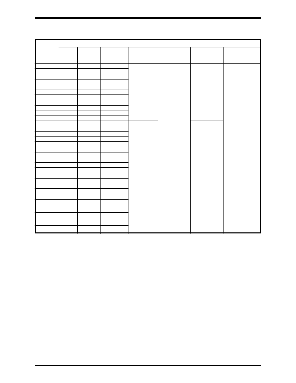
3.0 Standard Specifications
INPUT POWER (Volt/Freq)RATING
MODEL RATED MOTOR OUTPUT OUTPUT OVERLOAD MAIN CIRCUIT CONTROL
KVA HP/KW CURRENT VOLTAGE CURRENT 3-PHASE CIRCUIT SINGLE
AMPS PHASE
*G2+2010 1 0.75/0.9 3.5 200-230V 150% FOR 200V/50Hz or NO EXTERNAL
*G2+2015 1.5 1/1.2 5 3-PHASE 120 SEC. 200-230V/60Hz CONTROL
*G2+2025 2.5 2/1.8 7
*G2+2035 3.5 3/2.5 10
*G2+2055 5.5 5/4.0 16
*G2+2080 8 7.5/5.5 22
*G2+2110 11 10/7.5 30
*G2+2160 16 15/11 45
*G2+2220 22 20/15 60
*G2+2270 27 25/18 70
*G2+2330 33 30/23 90
*G2+4015 1.5 1/0.75 2.7 400-460V 400V/50Hz or
*G2+4025 2.5 2/1.5 3.5 3-PHASE 400-460V/60Hz
*G2+4035 3.5 3/2.2 5
*G2+4055 5.5 5/3.7 8
*G2+4080 8 7.5/5.5 11
*G2+4110 11 10/7.5 15 380-460V 380V/50Hz or
*G2+4160 16 15/11 22 3-PHASE 400-460V/60Hz
*G2+4220 22 20/15 30
*G2+4270 27 25/18.5 38
*G2+4330 33 30/22 45
*G2+4400 40 40/30 55
*G2+4500 50 50/37 69
*G2+4600 60 60/45 83
*G2+4750 75 75/55 104
*G2+410K 100 100/75 138
*G2+412K 125 125/90 172 130% FOR
*G2+415K 150 150/110 206 195 SEC.
*G2+420K 200 200/150 275 110%
*G2+425K 250 250/200 343 CONTINUOUS
**G2+430K 300 300/225 415
(MAX VOLTAGE
UNDER NO LOAD)
(MAX VOLTAGE VOLTAGE +/- 10%
UNDER NO LOAD) FREQUENCY +/- 2Hz
MAX VOLTAGE
UNDER NO LOAD) FREQUENCY +/- 2Hz
110%
CONTINUOUS
VOLTAGE +/- 10%
FREQUENCY +/- 2Hz
VOLTAGE +/- 10%
SOURCE
REQUIRED
* These units are UL/CUL (Underwriters Laboratories Inc.) listed and CSA (Canadian Standards
Association) certified.
** Unit is UL/CUL listed only.
3 - 1
Page 13
TOSHIBA
3.0 Standard Specifications (Cont'd)
ITEM STANDARD SPECIFICATIONS
Control Control Method Sinusoidal PWM control
Output voltage regulation Same as power line.
Output frequency 0.5 to 400Hz (0.1 to 80Hz setting when shipped); maximum
frequency range is 30 to 400Hz *
Frequency setting 0.1Hz: Operating panel input; 0.03Hz: Analog input; 0.01Hz:
resolution Input through computer interface (against a 60Hz)
Frequency accuracy ±0.5% (at 25°C; ±10°C) against the maximum frequency
Voltage/frequency Either constant V/f or second-order nonlinear mode for variable
characteristics torque. "Max voltage" frequency adjustment (25 to 400Hz), voltage
boost adjustment (0 to 30%), start-up frequency adjustment
(0 to 10Hz)
Frequency setting signals 3k ohms potentiometer (a 1k to 10k ohms-rated potentiometer
can be connected). 0 to 10Vdc (input impedance: 30k ohms), 0 to
5Vdc (15k ohms), 4 to 20mAdc (250 ohms)
Output frequency Can be set to an arbitrary characteristic by setting 2 points.
characteristics of IV
terminal input signal
Frequency jump 3-point setting; setting jump frequency and band width
Upper/lower limit Upper limit frequency: 0 to maximum frequency
frequencies Lower limit frequency: 0 to upper limit frequency
PWM carrier frequency Adjusted in the range of 0.5kHz to 3kHz
switching
Operating Acceleration/deceleration 0.1 to 6000 seconds, switching of acceleration time 1 or 2,
functions time selection of S-shaped 1 or 2, or selection of acceleration/
deceleration patterns
Electrical braking G2+2010 to G2+430K; IGBT7 dynamic braking
DC injection braking Start-up frequency adjustment (0 to 10Hz),
braking voltage adjustment (0 to 20%),
braking time adjustment (0 to 5 seconds)
Forward or reverse run Forward run when F-CC closed; reverse run when R-CC closed;
reverse run when both F-CC and R-CC closed; coasting stop
when ST-CC open; emergency coast stop by a command from
operating panel
Jogging run Jogging run engaged when N.O. contact is closed. (adjustment
range 0 to 20Hz)
Multispeed run By opening and closing different combinations of CC, SS1, SS2,
and SS3, the set speed or seven preset speeds can be selected.
Automatic fault latch reset When a protective function is activated, the system checks main
circuit devices, and attempts the restart up to 5 times (deactivated
when shipped)
Soft stall Sustains a run in overload mode (set at OFF when shipped)
Automatic restart Smoothly recovers a normal run of a free-running motor utilizing
motor speed detection control.
Programmable RUN Allows setting of 7 different patterns of automatic operation
patterns
Protection Protective functions Stall prevention, current limit, overcurrent, overvoltage, short-
circuit at load, load-end ground fault, undervoltage, momentary
power interrupt, electronic thermal overload, main circuit over-
current at start-up, load-end overcurrent at start-up, regenerative
discharge resistor overcurrent or overload, fin overheat, and
emergency stop. Provisions for external fault signal.
Electronic thermal Standard motor/constant torque V/f motor switching, and
characteristics electronic thermal stall prevention activating level adjustment
Reset Resets inverter when N.O. contact is closed.
* Consult the factory for applications above 80 Hz.
3 - 2
Page 14
TOSHIBA
3.0 Standard Specifications (Cont'd)
ITEM STANDARD SPECIFICATIONS
Display 4-digit, 7-segment LEDs Output Frequency range 0.0 to 400Hz and OFF state
frequency/
OFF
Warning Stall preventive warning, overvoltage limit warning,
indications overload warning, power-end undervoltage warning,
DC main circuit undervoltage warning, setting errors,
EEPROM abnormality, and data transfer abnormality
warnings
Fault Overcurrent, overvoltage, load-end ground fault,
indications overload, armature overcurrent at start-up, load-end
overcurrent at start-up, regenerative discharge
resistor overcurrent or overload, and fin overheat
Data and Inverter status (forward/reverse run, frequency set
status value, output current, etc.) and each set value
Speed An arbitrary unit (revolution speed, linear velocity or
scaling the like) as well as output frequency can bedisplayed
Data A number is assigned to each inverter (for 0 to 31
storage inverters).
LED Charging Main circuit capacitors charging indicator
indicator
Output signals Fault detection signal One form C contact (250AC / 30Vdc)
Low speed/reach signals Open collector output (24Vdc, 50mA maximum)
Upper limit/lower limit Open collector output (24Vdc, 50mA maximum)
frequency signals
Frequency meter output Ammeter rated at 1mAdc at full scale, or voltmeter rated at
and ammeter output 7.5Vdc, 1mA
Enclosure type Type 1 (standard), type 12 (option kits available) *
Cooling method Convection-cooled G2+2010 thru G2+2055 and G2+4015 thru
G2+4080
Fan-cooled G2+2080 thru G2+2330 and G2+4110 thru G2+430K
Color Sherwin Williams Precision Tan #F63H12
Service Service environment Indoor, altitude 1000m (3,300 ft) maximum. Must not be exposed
conditions to direct sunlight, or subjected to corrosive or explosive gas
or mists.
Ambient temperature From -10 to 40°C (up to +50°C without the cover)
Relative humidity 90% maximum (no condensation allowed)
Vibration Acceleration at 0.5G maximum (20 to 50Hz), amplitude at 0.1mm
maximum (50 to 100Hz)
* Enclosure for G2+430K has a removable bottom panel that must be drilled or punched in
the field to accomodate the wiring system conduit.
3 - 3
Page 15
TOSHIBA
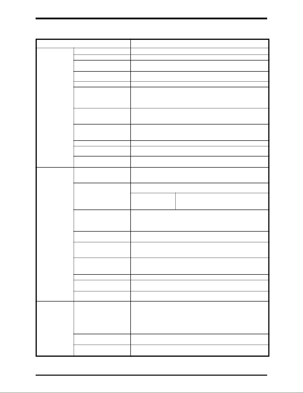
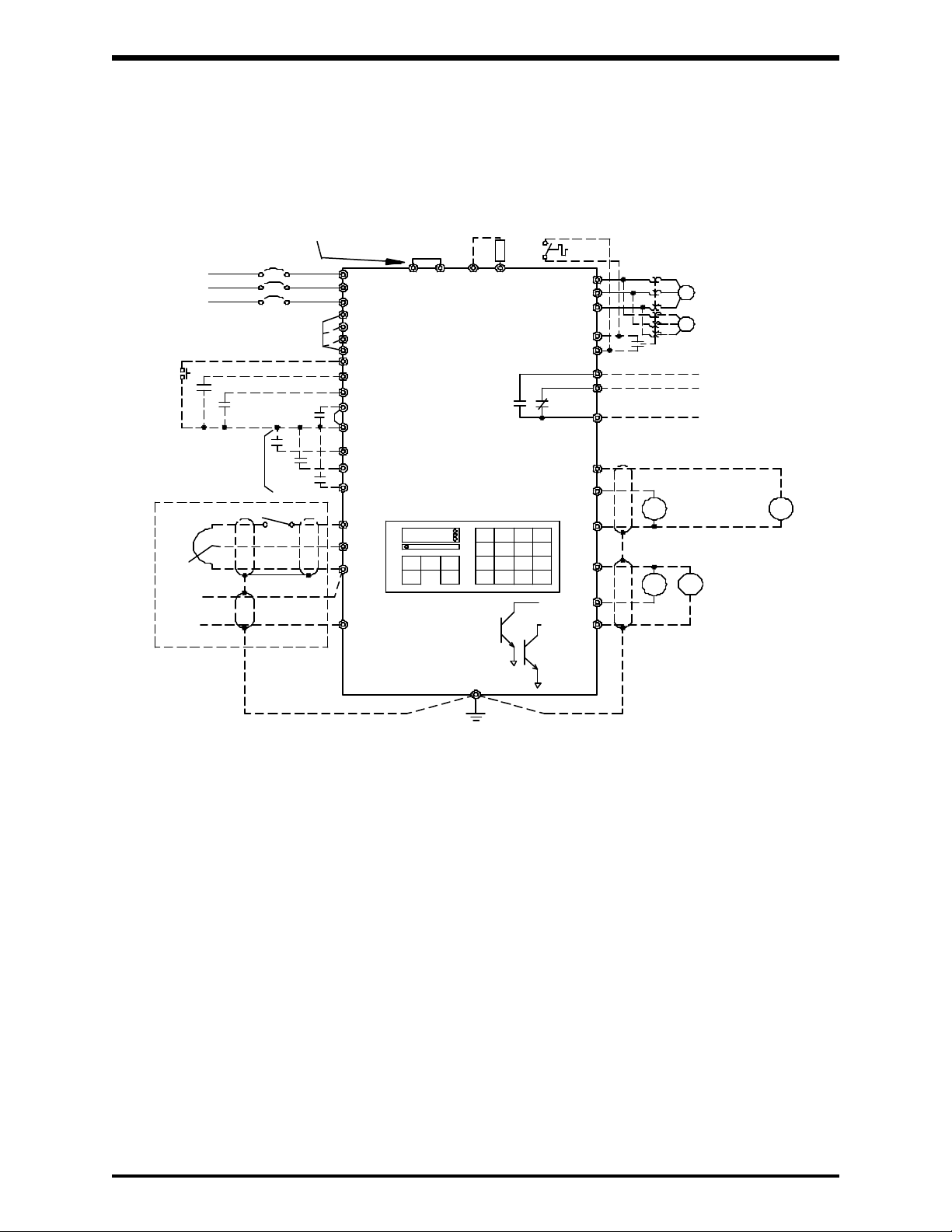
4.0 Wiring, PWB Layout, Jumpers, and Terminal Connections
4.1 Simple Connection Diagrams
TOSVERT-130G2+
STANDARD CONNECTION
MODEL 2010 TO 2330
POWER
SUPPLY
200VAC, 50Hz
200-230VAC, 60Hz
RESET
FORWARD DRIVE
REVERSE DRIVE
MULTI-FUNCTION
SIGNAL INPUT
ANALOG INPUT
FRH
-
AUTO
REFERENCE
+
MCCB
DRIVE
INTERLOCK
AUTO
HAND
L1(R)
L2(S)
L3(T)
RST
F
R
ST
CC
SS1
JOG/SS2
AD2/SS3
PP
RR
CC
IV
DBR
PA
PB
FAULT
DIGITAL
OPERATION PANEL
GND(E)
T1(U)
T2(V)
T3(W)
OH
OV
FLA
FLB
FLC
FM
AM
CC
P24
LOW/LL
RCH/UL
M
M
NORMALLY OPEN EXTERNAL
FAULT SIGNAL INPUT
FAULT SIGNAL OUTPUT
OUTPUT FREQUENCY SIGNAL
FULL SCALE AT 1mA
+
AM
OUTPUT CURRENT SIGNAL
+24Vdc
Ry Ry
MAX.
50mA EACH
100mA TOTAL
MULTI-FUNCTION
SIGNAL OUTPUT
+
FM
4 - 1
Page 16
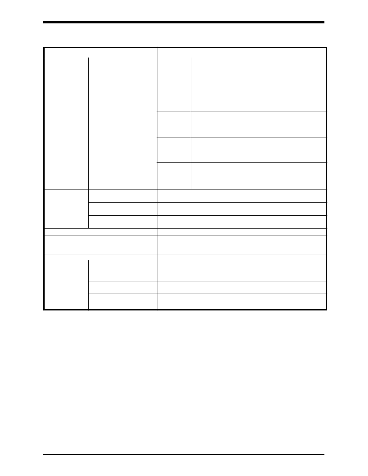
4.1 Simple Connection Diagrams (Cont'd)
TOSVERT-130G2+
STANDARD CONNECTION
MODEL 4015 TO 4080
TOSHIBA
POWER
SUPPLY
400VAC, 50Hz
380-460VAC, 60Hz
RESET
FORWARD DRIVE
REVERSE DRIVE
MULTI-FUNCTION
SIGNAL INPUT
ANALOG INPUT
FRH
-
AUTO
REFERENCE
+
MCCB
DRIVE
INTERLOCK
AUTO
HAND
L1(R)
L2(S)
L3(T)
RST
F
R
ST
CC
SS1
JOG/SS2
AD2/SS3
PP
RR
CC
IV
DBR
PA
PB
FAULT
DIGITAL
OPERATION PANEL
GND(E)
T1(U)
T2(V)
T3(W)
OH
OV
FLA
FLB
FLC
FM
AM
CC
P24
LOW/LL
RCH/UL
M
M
NORMALLY OPEN EXTERNAL
FAULT SIGNAL INPUT
FAULT SIGNAL OUTPUT
OUTPUT FREQUENCY SIGNAL
FULL SCALE AT 1mA
+
AM
OUTPUT CURRENT SIGNAL
+24Vdc
Ry Ry
MAX.
50mA EACH
100mA TOTAL
MULTI-FUNCTION
SIGNAL OUTPUT
+
FM
4 - 2
Page 17

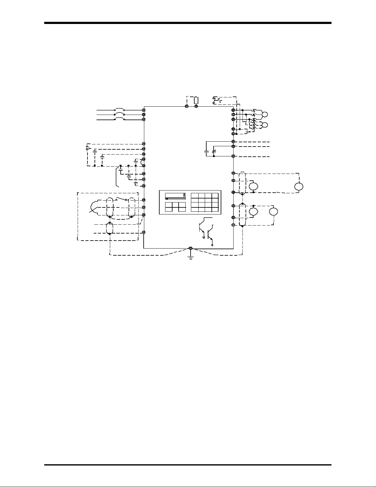
4.1 Simple Connection Diagrams (Cont'd)
TOSVERT-130G2+
STANDARD CONNECTION
MODEL 4110 TO 412K
TOSHIBA
POWER
MCCB
SUPPLY
INPUT POWER SELECTION
415/460V-50/60Hz
400/440V-50/60Hz
380V-50Hz
RESET
FORWARD DRIVE
REVERSE DRIVE
MULTI-FUNCTION
SIGNAL INPUT
ANALOG INPUT
FRH
-
AUTO
REFERENCE
+
DRIVE
INTERLOCK
AUTO
HAND
L1(R)
L2(S)
L3(T)
R41/46
R40/44
R38
RJ
RST
F
R
ST
CC
SS1
JOG/SS2
AD2/SS3
PP
RR
CC
IV
JUMPER
PDPC
PA
DIGITAL
OPERATION PANEL
GND(E)
PB
DBR
FAULT
T1(U)
T2(V)
T3(W)
OH
OV
FLA
FLB
FLC
FM
AM
CC
P24
LOW/LL
RCH/UL
M
M
NORMALLY OPEN EXTERNAL
FAULT SIGNAL INPUT
FAULT SIGNAL OUTPUT
OUTPUT FREQUENCY SIGNAL
FULL SCALE AT 1mA
+
AM
OUTPUT CURRENT SIGNAL
+24Vdc
Ry
MAX.
50mA EACH
Ry
100mA TOTAL
MULTI-FUNCTION
SIGNAL OUPUT
+
FM
4 - 3
Page 18
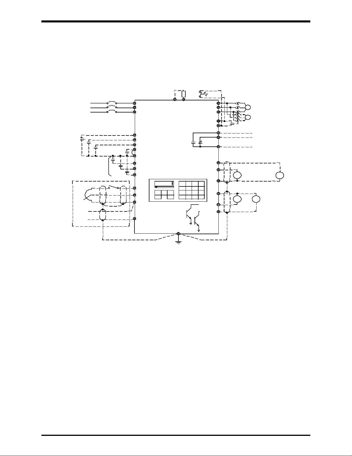
4.1 Simple Connection Diagrams (Cont'd)
TOSVERT-130G2+
STANDARD CONNECTION
MODEL 415K TO 430K
OPTIONAL REACTOR CONNECTION
POWER
SUPPLY
INPUT POWER SELECTION
415/460V-50/60Hz
400/440V-50/60Hz
RESET
FORWARD DRIVE
REVERSE DRIVE
MULTI-FUNCTION
SIGNAL INPUT
ANALOG INPUT
FRH
-
AUTO
REFERENCE
+
MCCB
380V-50Hz
DRIVE
INTERLOCK
AUTO
HAND
L1(R)
L2(S)
L3(T)
R41/46
R40/44
R38
RJ
RST
F
R
ST
CC
SS1
JOG/SS2
AD2/SS3
PP
RR
CC
IV
JUMPER
PDPC
PA
DIGITAL
OPERATION PANEL
PB
DBR
FAULT
T1(U)
T2(V)
T3(W)
OH
OV
FLA
FLB
FLC
FM
AM
CC
P24
LOW/LL
RCH/UL
TOSHIBA
M
M
NORMALLY OPEN EXTERNAL
FAULT SIGNAL INPUT
FAULT SIGNAL OUTPUT
OUTPUT FREQUENCY SIGNAL
FULL SCALE AT 1mA
+
AM
OUTPUT CURRENT SIGNAL
+24Vdc
Ry
MULTI-FUNCTION
SIGNAL OUPUT
MAX.
50mA EACH
Ry
100mA TOTAL
+
FM
GND(E)
4 - 4
Page 19
TOSHIBA
4.2 Selection of Main Circuit Wiring Equipment and
Standard Cable Sizes
Inverter circuit breaker (FLA x 1.25) **Typical cable size (AWG)
Type form rating (A) and 460Vac control command input, signal
G2+2010 15 4 #14
G2+2015 15 5.1 #14
G2+2025 20 9.8 #14
G2+2035 20 13.8 #14
G2+2055 30 21.9 #12
G2+2080 50 31.6 #10
G2+2110 70 40 #8
G2+2160 90 60 #6
G2+2220 100 78 #4
G2+2270 125 98 #3
G2+2330 150 115 #2
G2+4015 15 2.5 #14 #14 3-core shield cable #18
G2+4025 15 4.9 #14 2-core shield cable
G2+4035 15 6.9 #14
*Molded case Ampacity
(MCCB)
Amp Main power 230Vac and Frequency Other
(A) motor load power source frequency meter, circuits
ammeter
(speed reference)
#20
G2+4055 15 10.9 #14
G2+4080 30 15.8 #14
G2+4110 30 20.1 #12
G2+4160 40 30.2 #10
G2+4220 50 38.8 #8
G2+4270 70 48.8 #8
G2+4330 90 57.5 #6
G2+4400 100 74.8 #4
G2+4500 100 93.4 #3
G2+4600 125 110.7 #2
G2+4750 175 138 #1/0
G2+410K 200 178.3 #3/0
G2+412K 225 224.3 #4/0
G2+415K 300 258.8 *** 2 (#2/0)
G2+420K 350 345 *** 2 (#4/0)
G2+425K 400 428 *** 2(#4/0)
G2+430K 600 472 *** 2(#350)
See next page for notes.
4 - 5
Page 20

TOSHIBA
4.2 Selection of Main Circuit Wiring Equipment and
Standard Cable Sizes (Cont'd)
* The customer supplied Molded Case Circuit Breaker (MCCB) or Magnetic Circuit
Protector (MCP) should be coordinated with the available short circuit current. The
units are rated for output short circuit faults of 5000A (1 - 50 HP), 10,000A (51 - 200 HP),
and 18,000A (201 - 400 HP) according to the UL 508 "Standard for Industrial Control
Equipment" Table 57B.4 or CSA Standard C22.2 No.14-M1987 "Industrial Control
Equipment" Table 24. The selection of breakers for this table is in accordance with
1987 NEC Article 430. The selection of these breakers takes into consideration motor
starting at the low end of the output voltage specifications but does not consider the
use of high efficiency motors.
* For multiple motor applications, the magnetic only MCP should be replaced by a thermal
magnetic MCCB. The MCCB should be sized according to 1.25 X (largest motor Full
Load Amps) + (sum of all other motor Full Load Amps) to meet National Electric Code
(NEC) or Canadian Electrical Code (CEC) requirements.
** Wire sizing is based upon NEC table 310-16 or CEC Table 2 using 75 deg C cable, an
ambient of 30 deg C, cable runs for less than 300 FT., and copper wiring for not more
than three conductors in raceway or cable or earth (directly buried). The customer
should consult the NEC or CEC wire Tables for his own particular application and wire
sizing.
** For cable runs greater than 300 FT., consult the factory before installing.
*** Use two parallel conductors instead of a single conductor (this will allow for the proper
wire bending radius within the cabinet). Use separate conduits for routing parallel
conductors. This prevents the need for conductor derating (see note 3 this page).
Notes:
1.) Auxiliary relays used to switch inverter signals should be capable of switching
low current signals (i.e. 5mA).
2.) The inverter has internal overload protection, but the Local, National, or
Canadian Electrical Codes may require external motor overload protection.
3.) When wiring with parallel conductors, the conductors should be kept together in
phase sets with U1, V1, W1 in one conduit and parallel conductors U2, V2, W2
in another conduit. The ground conductor should be in one of these conduits.
Use separate conduits for routing incoming power, power to
CAUTION
motor, and control conductors. Use no more than three
power conductors and a ground conductor per conduit.
4.3 Grounding
The inverter should be grounded in accordance with Article 250 of the National Electrical
Code or Section 10 of the Canadian Electrical Code, Part I and the grounding conductor
should be sized in accordance with NEC Table 250-95 or CEC, Part I Table 16.
CAUTION
Conduit is not a suitable ground for the inverter.
4 - 6
Page 21
TOSHIBA
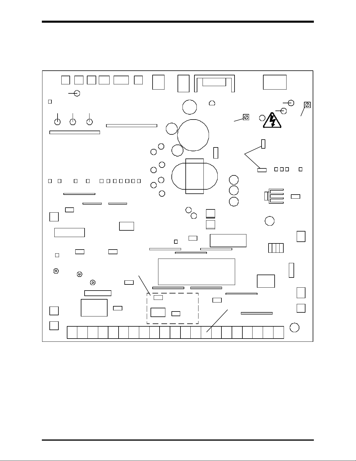
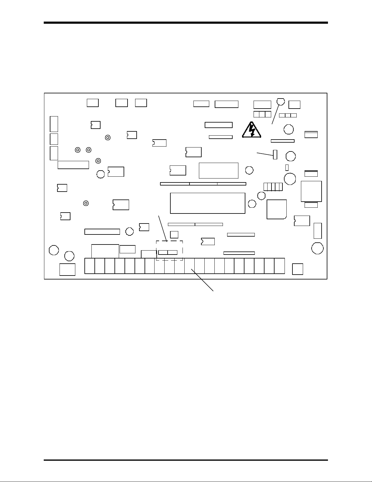
4.4 Control/Driver Board for G2+2010 through G2+2220
The following pictorial shows a layout of the major components located on the
control/driver board VF3B-0100.
CN15
CN1 CN2
CN12
CN3
CN20
CN4
CN11
CN7
CN5
Do Not
Adjust
Do Not
Adjust
RH1
CN6
RH2
Charge
LED
Do Not
Adjust
JP3
JP10
CN19
See Detail 1
Page 4-11
JP2
See Terminal Block Detail
Page 4-11
CP1
CN16
CP2
CP3
FL-RY
JP1
CN14
CN10
Note:
1) Potentiometer RH1 is used for control power supply stabilization. This adjustment is
factory set and any ADJUSTMENT BY THE USER SHOULD NOT BE ATTEMPTED.
2) Potentiometer RH2 is used for voltage detection level bias. This adjustment is factory
set and any ADJUSTMENT BY THE USER SHOULD NOT BE ATTEMPTED.
3) CP1, CP2,and CP3 are service testpoints.
4) Do not adjust JP3 and JP10.
5) Charge LED indicates charged capacitors. DO NOT TOUCH internal parts if lighted.
CN13
CN8
4 - 7
Page 22
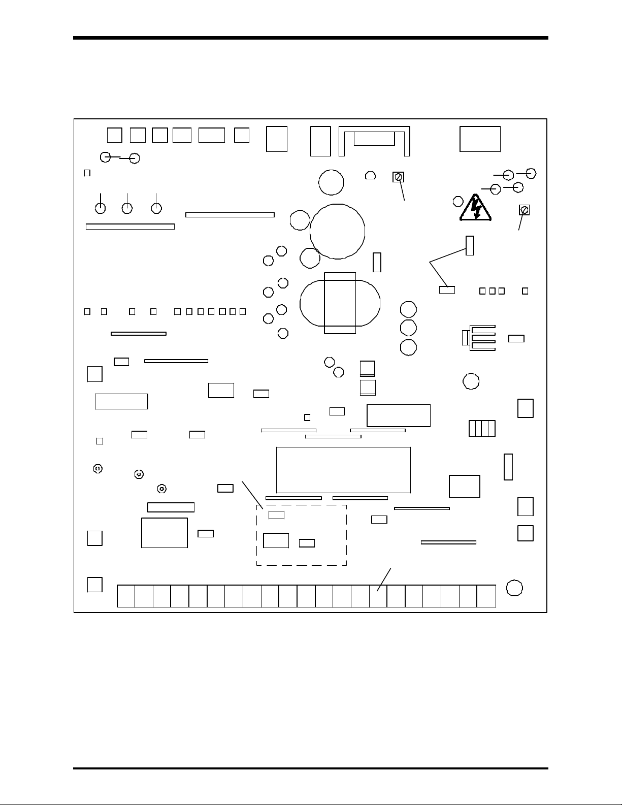
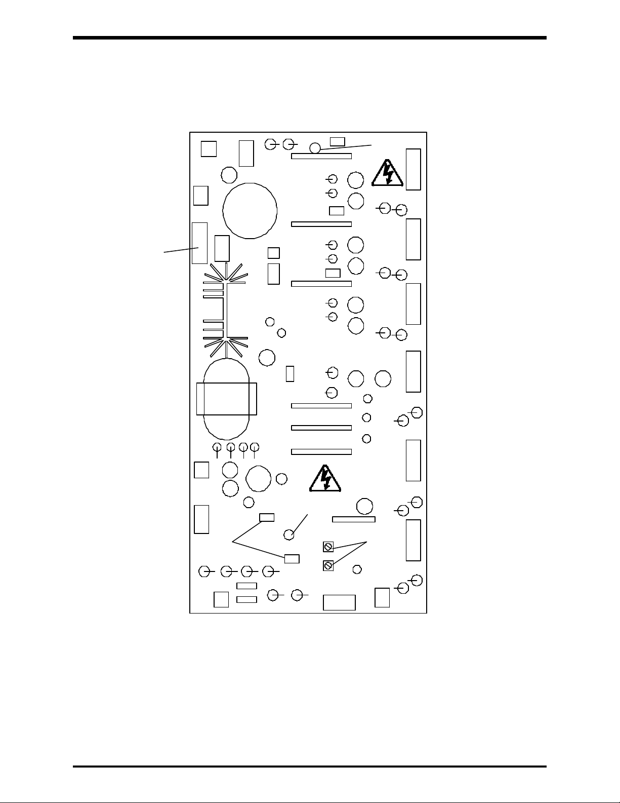
4.5 Control/Driver Board for G2+4015 through G2+4220
The following pictorial shows a layout of the major components located on the
control/driver board VF3B-0101.
TOSHIBA
CN15
CN12
CN4
CN20CN3CN2CN1
CN7
CN5
CN6
RH1
Charge
LED
Do Not
RH2
Adjust
Do Not
JP3
Adjust
Do Not
Adjust
JP10
CN11
CN19
CP1
CP2
CP3
See Detail 1
Page 4-11
JP2
CN16
FL-RY
JP1
CN14
CN10
See Terminal Block Detail
Page 4-11
Note:
1) Potentiometer RH1 is used for control power supply stabilization. This adjustment is
factory set and any ADJUSTMENT BY THE USER SHOULD NOT BE ATTEMPTED.
2) Potentiometer RH2 is used for voltage detection level bias. This adjustment is factory
set and any ADJUSTMENT BY THE USER SHOULD NOT BE ATTEMPTED.
3) CP1, CP2, and CP3 are service testpoints.
4) Do not adjust JP3 and JP10.
5) Charge LED indicates charged capacitors. DO NOT TOUCH internal parts if lighted.
CN13
CN8
4 - 8
Page 23
TOSHIBA
4.6 Control Board for G2+2270 through G2+2330 and
G2+4270 through G2+430K
The following pictorial shows a layout of the major components located on the
control board VF3C-1200.
CN4
CN5CN6
CN7
CP4
CN12
CN4B
CP1
CP3
CP2
FL-RY
CP5
CN4A
CN4C
See Detail 2
Page 4-11
JP1 JP2
CN10
Do Not
Adjust
CN3CN2CN11
Charge
LED
CN20
JP4
CN1
CN8
See Terminal Block Detail
Page 4-11
Note:
1) CP1, CP2, CP3, CP4, and CP5 are service testpoints.
2) Do not adjust JP4.
3) Charge LED indicates charged capacitors. DO NOT TOUCH internal parts if lighted.
4 - 9
Page 24
4.7 Driver Board for G2+2270 through G2+2330 and
G2+4270 through G2+430K
The following pictorial shows a layout of the major components located on the
driver board 35589/VT3D-2039
Power
CN6A
CN5A
LED 1
TOSHIBA
CN11
FUSE
AC250V
1A
CN1A
CN2A
Do Not
Adjust
J4
J21
Charge
LED 21
21RH
Do Not
Adjust
CN31
CN21 CN61 CN41 CN51
CN91
22RH
CN3A
CN71
Note:
1) Potentiometer 21RH (OP) is the main circuit overvoltage detection trip set. This
adjustment is factory set and any ADJUSTMENT BY THE USER SHOULD NOT BE
ATTEMPTED.
2) Potentiometer 22RH (MUV) is the main circuit undervoltage detection trip set. This
adjustment is factory set and any ADJUSTMENT BY THE USER SHOULD NOT BE
ATTEMPTED.
3) Do not adjust J4 and J21.
5) Charge LED indicates charged capacitors. DO NOT TOUCH internal parts if lighted.
4 - 10
Page 25

TOSHIBA
4.8 Jumper Details
10V 5V
The jumper connections for each of the printed wiring boards on Pages 4-7 through
4-9 are shown in the enlarged details below. Only jumpers JP1 and JP2 should be
adjusted by the user. See Page 8-12 for jumper adjustments.
JP2
VI
JP1
Detail 1 (Reference pages 4-7 and 4-8)
I V 10V 5V
JP1
Detail 2 (Reference page 4-9)
4.9 Control/Driver Board Terminal Block Details
The control/driver board terminal block is shown in detail below. Each of the twenty-one
terminals is functionally labeled. See Pages 4-12 and 4-13 for a list of terminal functions.
See sections 8.4, 8.5, and 8.6 for terminal connection applications.
Control/Driver Board Terminal Block Detail (Reference pages 4-7, 4-8, and 4-9)
LOWRCH
(UL)
FMFLA P24FLCFLB PPAM
(LL)
RR IV CC ST F R CC SSI
JP2
(SS2)(SS3)
AD2JOG
CCRST
4 - 11
Page 26
TOSHIBA
4.10 Terminal Connections and Functions
Terminal Terminal functions Terminal
name location
L1, L2, L3 Connect these terminals to either a 3-phase 50Hz, 200Vac power
(R, S, T) supply or to a 3-phase 60Hz, 200 to 230Vac power supply for
models G2+2010 to G2+2330.
Connect these terminals to either a 3-phase 50HZ, 400Vac power
supply or to a 3-phase 60HZ, 400 to 460Vac power supply for
models G2+4015 to G2+430K.
T1, T2, T3 Connect these terminals to a 3-phase induction motor of the
(U, V, W) proper voltage.
PA, PB Connect these terminals to a regenerative discharge resistor.
FLA, FLB, FLC This form C contact changes state when a protective function has
been activated (250Vac - 2A).
P24 Unregulated 24Vdc power supply (24Vdc, 100mA maximum).
RCH(UL) Outputs a signal when the upper limit frequency is reached, when
an acc/dec is complete, or when the output frequency is within a
specified range. The choice is determined by the function selection
terminal RCH(UL). Terminal provides an open-collector output
(50mAdc).
LOW(LL) Outputs a signal when a preset low speed or a preset lower limit is
reached. The choice is determined by the function selection of the
terminal. Terminal provides an open-collector output
(50mAdc max).
Bus bar
or
power
terminal
block
FM This terminal can be connected to an external analog frequency
meter. Use either an ammeter rated at 1mAdc at full scale or a
voltmeter rated at 7.5Vdc at full scale.
AM This terminal can be connected to an external analog ammeter.
Use either an ammeter rated at 1mAdc at full scale or a voltmeter
rated at 7.5Vdc at full scale.
PP Provides a 10Vdc power supply to be used with terminal RR for
remote terminal input.
RR Provides an input terminal for a 0~5Vdc or 0~10Vdc input reference
signal. Also used for wiring a 1k~10k ohm (3k ohm recommended)
potentiometer to allow for remote speed control operation.
IV Input a frequency reference signal to this terminal. 0 to 5 Vdc (with
JP1 set at V), or 4 (0) to 20mAdc (with JP1 set at I)
CC This is the common end of the FM, AM, and P24 terminals.
Do not connect to GND(E).
4 - 12
Control
PWB
terminal
block
Page 27
TOSHIBA
4.10 Terminal Connections and Functions (Cont'd)
Terminal Terminal functions Terminal
name location
ST With ST-CC shorted, the inverter is ready to run. With ST-CC open,
a coasting stop phases in. This terminal can be used as a run
interlock.
F With F-CC shorted, a forward run is engaged. With F-CC open,
deceleration phases in for a complete stop. (ST-CC is shorted.)
R With R-CC shorted, a reverse run is engaged. With R-CC
open, deceleration phases in for a complete stop. (ST-CC is
shorted.) (If both F-CC and R-CC are shorted simultaneously,
a reverse run will result.)
CC This is the common end of the PP, RR, and IV terminals.
Do not connect to GND(E).
SS1 With SS1-CC shorted, a multispeed run is engaged.
JOG(SS2) With JOG-CC shorted, a jogging run is engaged: With SS2-CC
shorted, a multispeed run is effected. (See Section 8.4.3)
AD2(SS3) With AD2-CC shorted, an ACC/DEC run is engaged; or with SS3-
CC shorted, a multispeed run will result. (See Section 8.4.4)
RST With RST-CC shorted, the inverter's protective function resets.
CC This is the common return for the ST, F, R, SS1, JOG(SS2),
AD2(SS3), and RST terminals. Do not connect to GND(E).
OH External fault signal input.
OV Common connection for OH terminal.
GND(E) The inverter earth ground terminal.
Do not connect to common return terminal (CC)
R41/46 * Jumper to RJ when using 415V-50Hz/460V-60Hz incoming.
Do not jumper to R40/44 or R38.
Control
PWB
terminal
block
Terminal
block
Frame
screw or
lug
R40/44 * Jumper to RJ when using 400V-50Hz/440V-60Hz incoming.
Do not jumper to R41/46 or R38.
R38 * Jumper to RJ when using 380V-50Hz incoming.
Do not jumper to R41/46 or R40/44.
RJ * Common control voltage jumper terminal. Connects to R41/46 or
R40/44 or R38. Do not jumper to more than one terminal.
* Supplied only on the G2+4110 - G2+430K units.
4 - 13
Terminal
block
Page 28
5.0 Features
5.1 Function Setting and Status Monitoring
· Multifunctional User-Friendly Operating Panel
· Direct Access of All Functions
· Ability to Change Function Settings Even While Motor is Running
· One Touch Status Monitoring
· Remote Operating Panel
· Ability to Reset All Functions to Initial Factory Settings
setting up for a particular application, it is usually easier to reset the inverter to factory
TOSHIBA
Commands are easily entered via the inverter's keyboard type operating panel. The
operating panel enables the user to run/stop the inverter, read/change the operating
function settings, and monitor the operating conditions of the inverter. All these
operations are accomplished via the inverter's user-friendly software, keypad, and
7 segment LED display. See section 6 for details on the operating panel.
With the G2+, the user can directly access and change any of the built-in functions.
The software was designed to make programming and set-up time extremely fast
and easy. There is no need to scroll through a long list of functions or flip numerous
dip switches just to set one particular function.
Accessing and setting the individual functions can be performed with or without a
motor being attached. In fact, all but two of the inverter's functions can be accessed
and changed while an attached motor is running.
Monitoring the inverter's operating conditions requires the pressing of a single key.
Items which can be monitored include the inverter's output current and output voltage.
See section 7.5 for a complete list of items.
The NEMA 4/12 operating panel can be placed up to 5M (15ft) from the inverter's
chassis, without any additional electronics, simply by using an optional cable. This
feature allows for the continued ease of operation should the inverter be placed
inside an enclosure.
In cases where an unknown number of functions may become misadjusted when
settings and start over rather than search for the misadjusted functions. Refer to "First
and Second Functions Factory Setting Overview" section 6.6 for these settings.
The example on the following page shows how easy it is to access and set a function.
The standard setting mode of function 0 establishes the nominal operating frequency
of the motor that is selected. This function is also used to set all functions back to their
original factory settings. The example shows this is done by setting "typ" to 3.
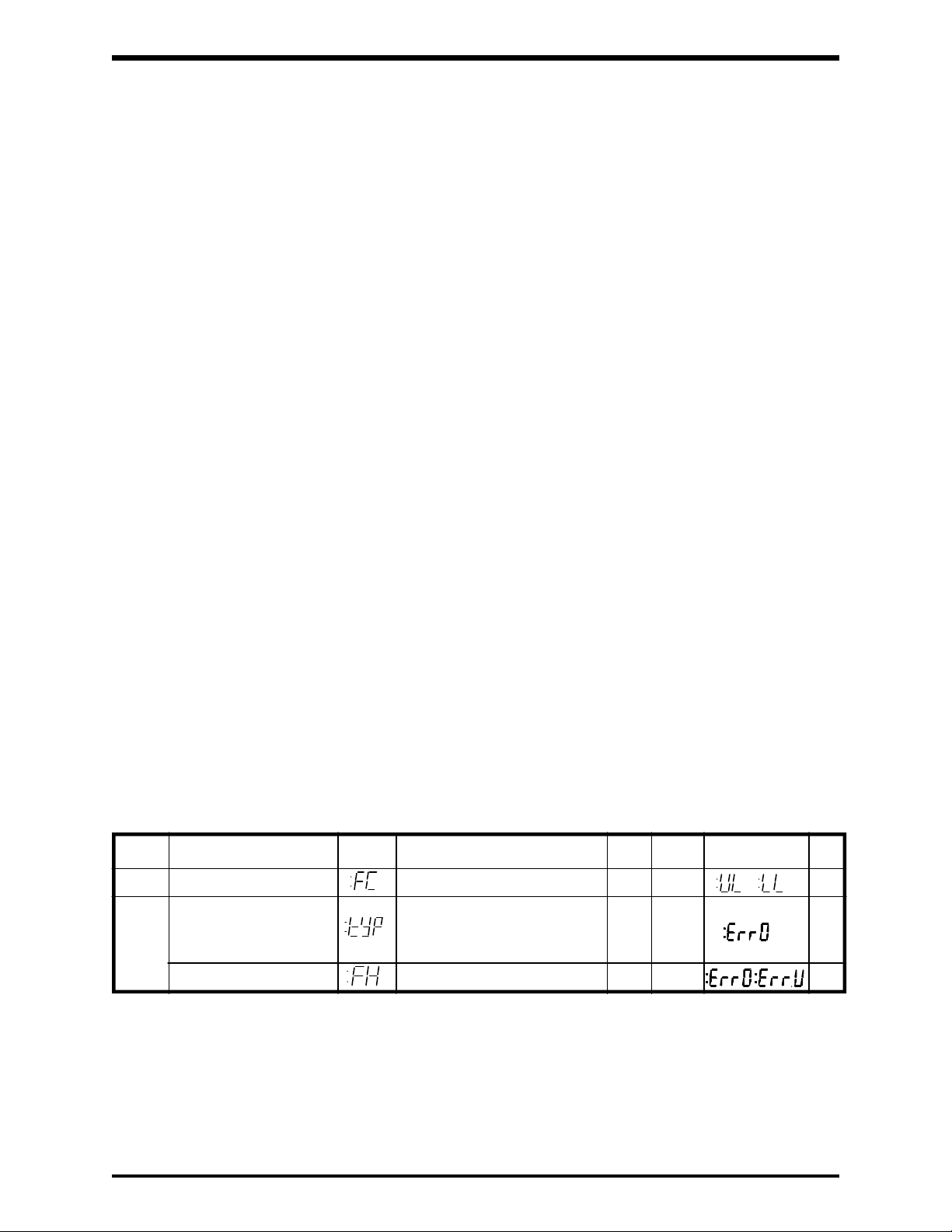
Function Parameters
Function Function Adjustment Factory Error Ref.
No. Name Display Range Unit Set Message Page
- Frequency setting 0.1~400 Hz 0 8-6
Standard setting mode 1: 50Hz motor 3
0 3: Factory set
Maximum frequency 30 to 400 Hz 80 8-21
2: 60Hz motor 8-21
5 - 1
Page 29
TOSHIBA
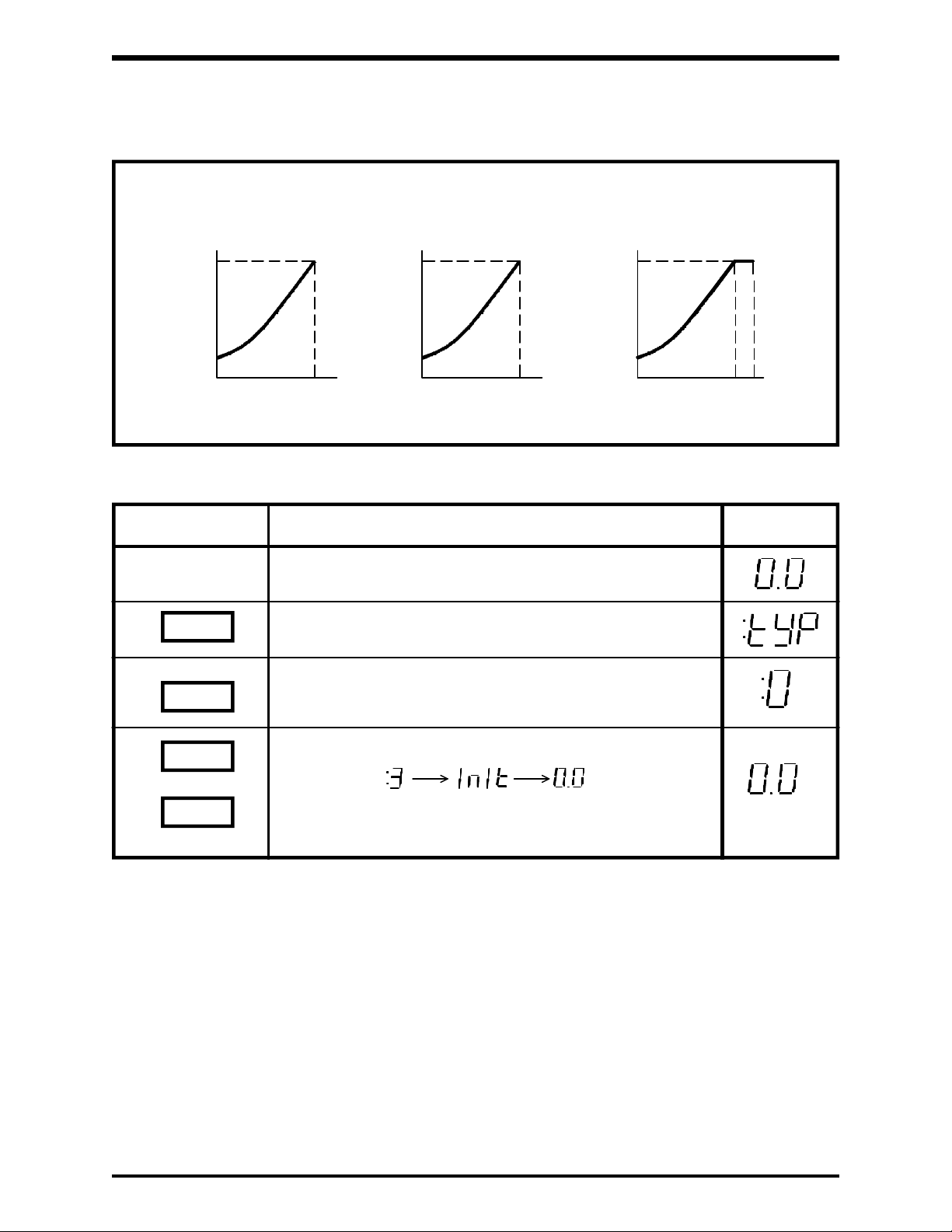
5.1 Function Settings and Status Monitoring (Cont'd)
V/F Characteristics of the Standard Setting Mode
"tYP=1"
General purpose
50Hz setting
100%
Output
voltage
3%
0
Output frequency
KEY ACTION DISPLAY
MON
50Hz
Assume the inverter is in the monitor mode and not
running.
The inverter is now in the function mode and
has accessed Function #0.
100%
Output
voltage
3%
"tYP=2"
General purpose
60Hz setting
0
Output frequency
60Hz
100%
Output
voltage
3%
"tYP=3"
Standard setting
upon shipment
0
Output frequency
60
80Hz
Displays the value currently set for "tYP". When reading
READ
3
WRT
this function and only this function the value displayed
will always be zero.
Resets all 96 built-in functions back to factory settings.
:
Used in cases where starting over is easier than
searching for misadjusted functions.
5.2 "96" Built-in Functions for Complete Operating Control
The G2+ inverters have a wide variety of operating functions with each function having
a wide adjustment range. To the user, this means that almost any application can be
controlled to produce maximum output at minimum cost. For ease of programming,
functions are classified into first and second functions. See the Factory Overview
Chart on page 6-7 for a complete list of the Built-in Functions.
5 - 2
Page 30
TOSHIBA
5.3 Voltage Matching
5.3.1 Proportional Output Voltage (Standard)
This feature allows programming the inverter to deliver an output voltage that
is an exact percentage of the input voltage. The output voltage can range from
0% to 100% of the input voltage. The word "proportional" comes from the fact
that if the input voltage level rises or falls during operation, the output voltage
follows in direct proportion. The following examples illustrate this feature.
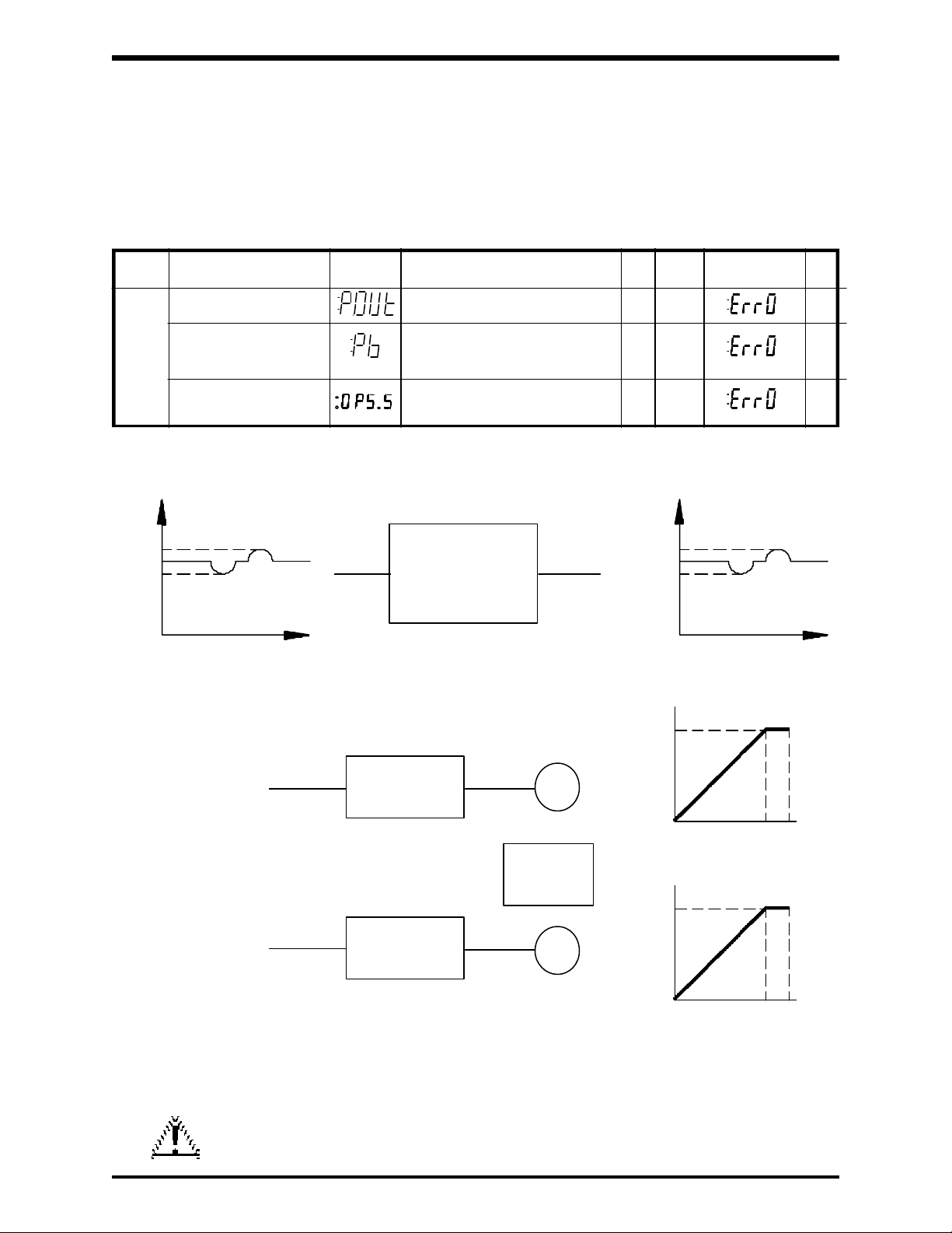
Function Parameters
Function Function Adjustment Factory Error Ref.
No. Name Display Range Unit Set Message Page
Output voltage adjustment 0 to 100 (Option: 0 to 120) % 100 8-27
2ND
4 0: Non DBR
Dynamic brake resisitor 1: DBR, No OLr detection (*1 pg 6-10) 0 8-27
Auto deceleration on the 0: On 0 8-27
: Pb=0 1: Off
Voltage
2: DBR, OLr detection (*1 pg 6-10)
Example 1
Voltage
260V
230V
200V
Power supply 230V
Power supply 230V
Time
Note:
226V
Input
G2+
Proportional Output
Voltage (P.Out)
Output
200V
174V
Time
set to 87%
Example 2
230V
G2+
Motor rated at 230V
G2+
Motor rated at 200V
For ease of identification the inverters are listed in horsepower.
However the real determining factor, when sizing an inverter, is the rated
current capability. Therefore, the user must be aware that a reduction in
motor voltage means higher currents will be required.
M
60 80Hz
200V
M
60 80Hz
CAUTION
Be sure that the inverter's rated current capability is always
greater than the total current required.
5 - 3
Page 31

TOSHIBA
5.3.2 Output Voltage Regulation (Optional)
This optional feature enables the user to maintain a constant output voltage
even if voltage fluctuations occur at the input. For minimal fluctuations, the V/F
characteristics can be maintained at a constant level by automatically regulating
the output voltage. Instantaneous fluctuations should be minimized by the use
of an input AC line reactor. The use of this feature insures that the proper V/F
characteristics will be applied in critical applications. Also this minimizes the
danger of motor over excitation due to an elevated input voltage.
Note:
Contact TOSHIBA for latest information concerning this option.
Voltage
260V
230V
200V
Input Output
G2+
P.Out = 100%
with Optional Output
Voltage Regulation
Voltage
200V
TimeTime
5 - 4
Page 32

5.4 Tosvert-130 G2+ Options
5.4.1 3-Component Remote Station
This remote station includes a speed potentiometer, on/off selector switch, and
a analog frequency meter.
5.4.2 4-Component Remote Station
This remote station includes a speed potentiometer, a analog frequency meter,
and start and stop push buttons (user must supply relay logic to hold start signal).
5.4.3 Multi-Function Option Board
The Tosvert-130 G2+ Multi-Function Option Board will perform the following
ten (10) functions:
1.) Computer interface (RS232C)
2.) Speed feedback control (TG or PG)
3.) Seven pre-set speeds using acceleration/deceleration time one or two.
4.) BCD or 12 bit binary input for frequency setting
5.) +/- 10Vdc forward/reverse frequency setting signal input
6.) Pulse input for frequency setting
7.) Control signal output to switch between inverter and bypass contactor
8.) Overload detection output proportional to frequency and current
9.) 0-1 mAdc analog signal output proportional to frequency and current
10.) Ninety six (96) times frequency pulsed output
TOSHIBA
Although the Multi-Function Option Board performs these ten (10) separate
functions, some functions cannot be used simultaneously with other functions.
Consult the Toshiba Inverter Marketing department for each individual function
to determine what options cannot be used with that corresponding function.
5.4.4 RS232C Option Board
Computer interface (RS232C) only option board
5.4.5 RS232 Cable
Cable connects option board to IBM (TM) compatible computer
5.4.6 RS485 Multi-Function Option Board
The Tosvert-130 G2+ RS485 Multi-Function Option Board will perform the
following five (5) functions:
1.) Computer interface (RS485)
2.) PG speed feedback control
3.) Pre-set speeds with Accel/Decel 1 & 2
4.) BCD or 12 bit binary for frequency setting
5.) Pulse input for frequency setting
Although the RS485 Multi-Function Option Board performs these (5) separate
functions, some functions cannot be used simultaneously with other functions.
Consult the Toshiba Inverter Marketing department for each individual function
to determine what options cannot be used with that corresponding function.
5.4.7 TG/PG Option Board
Tach generator or pulse generator speed feedback control only.
5 - 5
Page 33

TOSHIBA
5.5 Multiple Preset Speeds
Output
frequency
· Up to 7 different preset speeds can be executed without any external potentiometers.
· These 7 preset speed frequency values can be accessed either through the terminal
input (Remote Control) or through the keypad (Panel Control). Also note that an
8th speed can be executed when the inverter has an operating frequency set
through the terminal input reference signal.
· The preset frequencies are set to particular frequencies via Function #6 - parameters
SR1 thru SR7.
EXAMPLE
1st speed (Sr1)
2nd speed (Sr2)
3rd speed (Sr3)
4th speed (Sr4)
5th speed (Sr5)
6th speed (Sr6)
7th speed (Sr7)
Time
ST
R
F
SS1
SS2
SS3
CC
ST-CC
ON
F/R-CC
ON
SS3-CC
OFF
OFF
OFF
OFF
ON
ON
ON
ON
SS2-CC
OFF
OFF
ON
ON
OFF
OFF
ON
ON
SS1-CC
OFF
ON
OFF
ON
OFF
ON
OFF
ON
Operating Frequency Selection
Operating Frequency set via PP, RR, IV terminal
1st Operating Speed Frequency
2nd Operating Speed Frequency
3rd Operating Speed Frequency
4th Operating Speed Frequency
5th Operating Speed Frequency
6th Operating Speed Frequency
7th Operating Speed Frequency
Preset Functions Required To Run the Preset Speeds
Function Function Adjustment Factory Error Ref.
No. Name Display Range Unit Set Message Page
1st speed LL to UL setting value Hz 0 8-23
2nd speed LL to UL setting value Hz 0 8-23
3rd speed LL to UL setting value Hz 0 8-23
6 4th speed LL to UL setting value Hz 0 8-23
5th speed LL to UL setting value Hz 0 8-23
6th speed LL to UL setting value Hz 0 8-23
7th speed LL to UL setting value Hz 0 8-23
8 Multi-function input 0 : SS2, SS3 0 8-24
1 : JOG, SS3
2 : SS2, AD2
3 : JOG, AD2
5 - 6
Page 34

5.6 Programmable Run Patterns
Pattern 1 (ACC #1 of #2)
Pt.1
Forward run
Pattern 2 (ACC #1 or #2)
Pt.2
Sr2
Pattern 3 (DEC #1 or #2)
Pt.3
TOSHIBA
Pattern 5 (DEC #1 or #2)
Pattern 4 (DEC #1 or #2)
Pt.4
Sr1
0
Output frequency
Reverse run
Pt.1t Pt.2t Pt.3t
Pattern 3 (ACC #1 or #2)
Pt.3
Sr3
Pattern 5 (ACC #1 or #2)
Pt.5
Sr4
Sr5
Pattern 5Pattern 4Pattern 3Pattern 2Pattern 1
Pt.4t
Pt.5t
· Up to 7 different preset speed patterns can be automatically executed to produce
what is known as a Pattern Run.
· Each speed can be set to operate in the range of 0 to 8000 seconds or minutes.
· Each pattern can be set to accelerate/decelerate using either one of the two
acceleration/deceleration functions.
· Each pattern can be set to operate in either the forward or reverse direction.
. Pattern may be repeated 0 to 254 times or repeat infinitely.
Preset Functions Required To Perform the Pattern Run
Function Function Adjustment Factory Error Ref.
No. Name Display Range Unit Set Message Page
1st speed LL to UL setting value Hz 0 8-23
Time
2nd speed LL to UL setting value Hz 0 8-23
6 3rd speed LL to UL setting value Hz 0 8-23
4th speed LL to UL setting value Hz 0 8-23
5th speed LL to UL setting value Hz 0 8-23
6th speed LL to UL setting value Hz 0 8-23
7th speed LL to UL setting value Hz 0 8-23
Pattern run activation 0: Off 0 8-28
mode 1: Terminal operation
Time unit 0: Seconds 0 8-28
Cycle times 0 to 255 0 8-28
2ND Pattern drive time 0 to 8000 sec 0 8-28
8 #1 to 7 to min
Pattern drive characteristics 0: Forward run, #1 ACC/DEC
#1 to 7 to 1: Forward run, #2 ACC/DEC 0 8-28
F/R, ACC/DEC 2: Reverse run, #1 ACC/DEC
2: Touch pad operation
3: Computer communication
1: Minutes
(255: Infinity operating)
3: Reverse run, #2 ACC/DEC
5 - 7
Page 35

TOSHIBA
5.7 Accelerating/Decelerating Characteristics
· ACC/DEC time can be set in the range of 0.1~6000 seconds.
· ACC/DEC time 1 or 2 can be selected either through the keypad (Panel Control) or
an input terminal (Remote Control).
· ACC/DEC characteristics can be selected from the linear, S-shaped, or
C-shaped pattern.
Linear pattern S-shaped pattern C-shaped pattern
Max output
frequency
Frequency
The S-shaped pattern gradually accelerates a motor in a range where the motor
provides a low torque, and is suited for material handling machinery.
The C-shaped pattern quickly accelerates a motor in a range where the motor
provides a low torque, and is suited for a high speed run.
5.8 Display Frequency Scaler
This versatile unit indication system permits the indication of not only the output
frequencies, but also revolution speeds, linear velocities, or other linear multiples of
the frequencies.
[Contents of digital displays]=Constant X [Output frequency]
The constant can be set within the range 0.01~200; also the unit measure (Hz) LED
turns off when the Display Frequency Scaler function is activated.
Example:
When a 4 pole motor is driven at 0~60Hz, the setting "dSP.2=30" makes the monitor
display indicate 0~1800 (rpm).
For linear speed of 6m/sec at 60Hz, set "dSP.2=0.1". When speed scaling is used, the
unit of measure LED is turned off.
Max output
frequency
Frequency
Time TimeTime
Max output
frequency
Frequency
5.9 Memory Function
A number from 0 to 31 can be assigned to and stored in the non-volatile memory of
the inverter. This allows electronic tagging and on-line identification of each unit.
This function can be utilized for sorting of inverter unit numbers and various set data
through the optional computer interface.
5 - 8
Page 36

Output
frequency
5.10 Braking Characteristics
5.10.1 DC Injection
The DC injection braking function creates smooth operating characteristics with
continuous phase control. It is used primarily for alignment applications. It
controls the final coast of the motor by injecting DC voltage into the motor. This
allows the capability of starting and stopping at the same point every time when
used in conjunction with a position sensor. The amount of DC energy that is
available for injection is limited by the current limiting feature of the inverter. Care
should be taken when using DC injection because of additional motor heating.
Standard deceleration
DC injection braking
DC injection braking start-up frequency
Time
TOSHIBA
Motor excitation
de-energizing
Output
frequency
Free-run
Time
Output voltage
(effective value)
Across ST-CC
Across F-CC
DC injection braking voltage
Note:
See standard specifications (page 3-2) for adjustment ranges.
5.10.2 Dynamic Braking
Dynamic braking is used to rapidly decelerate the motor load (especially high
inertia loads) by converting the energy generated by the motor into heat. The
heat is dissipated through the DB resistor. Models G2+2010 through G2+430K
can be equipped with an optional dynamic braking resistor (DBR) to boost the
braking torque. When DBR's are installed:
1) Install a magnetic contactor (MC) or a molded case circuit breaker
(MCCB) with a trip coil on the inverter's power supply side. This
opens the power circuit when the inverter's built-in fault detecting relay
(FL) or an externally mounted overload relay is activated.
2) For all models, connect the dynamic braking resistor (DBR) bank to
the PA-PB terminals of the main circuit terminal block.
3) The DB resistors should not be installed where the ambient temperature
of the inverter will exceed 40°C.
5 - 9
Page 37

TOSHIBA
5.10.2 Dynamic Braking (cont'd)
4) DB resistors should be installed as near to the inverter as possible with
temperature constraints in mind.
Note:
5) Exercise caution when working around
extremely hot when used in conjunction with long duty cycles and high
inertia loads.
6) PA-PB dynamic braking
high DC bus voltage potential. Do not touch PA - PB terminals when
the charge or power LED lamp is on.
Consult factory for DBR sizing.
CAUTION
DANGER
the DB resistors; they can become
resistor (DBR) terminals are at
5 - 10
Page 38

6.0 Functions
6.1 Operating Panel
The operating panel enables the user to run or stop (RUN/STOP) the inverter, read
and/or change the operating function parameter values (READ/WRT), and monitor
(MON/NEXT) the operating conditions of the unit (see key function section 6.5).
Basic Operating Keys - Display Function Access/Set - Status Keys
TOSHIBA
Operating Panel
The Panel Control LED will be lit when
in the panel control mode
Toggles between the panel control
mode and the remote control mode.
The control mode cannot be changed
while the inverter is running.
The 7 segment LED displays the
inverter's output frequencies, function
parameter titles/values, fault codes,
status codes, etc.
Unit of measurement
for value displayed.
PANEL CONTROL
Hz
%
SEC
Switches to second function mode when in
the first function mode. Switches to status
monitoring when in the monitor mode (see
section 7.5).
Toggles between the monitor mode and
first function mode .
Multifunctional data keys (one of eleven)
used to access, read, and write the function
parameter settings.
Note: Keys "0-9" have 3 separate functions:
numerical value, first functions and second
functions (only first and second functions are
depicted on the key).
Key for "decimal point" has only 2 separate
functions: decimal point and first functions.
JMP TB SEL
MON
7 98
OL REF JOG
2ND
4 5 6
CTRL
RUN
RUN/STOP Keys used to
start and stop the inverter.
"UP"/"DOWN" scroll keys used for changing the
inverter's operating frequency and function parameter
settings. Can also be used, during special operations,
for engaging forward/reverse runs and for calibrating
remote meters.
STOP
6 - 1
CLR
NEXT
V/F
ACC/DEC
UL/LL
1 2 3
FMAX READ
WRT
.0
Writes (stores) each line of data into
the inverter's non-volatile memory (loss
of power does not destroy data).
Cycles through each of the parameters
in the first or second function mode, as well
as the inverter's status conditions when in
the monitor mode.
Clears the display.
Note: Must press CLR WRT to clear
the display after a trip.
Page 39

TOSHIBA
6.2 LED Display
The LED display provides the user with the operating frequency, function settings, and
status information necessary to easily monitor and set the operating parameters. The
individual LED's are identified and explained in the following chart.
1
3
5
4
PANEL CONTROL
2
Item Name Function/status
1 Monitor display 7-segment, 4-column LED
Displays frequency, title, data, etc.
2 Panel control LED When ON the unit is in the panel control mode
When OFF the unit is in the remote control mode
When FLASHING the unit is in the panel control mode and the motor is running
3 Super mode LED When ON the computer interface option is enabled. (Contact Toshiba
for information.)
4 Monitor display Normally OFF when displaying operating frequency or unit frequency scaler.
LED
5
ON when unit is in a patterned run sequence
Monitor Display
Hz
%
SEC
6
7
8
ON when in function setting mode via operating panel and unit is not
running.
Flashing when in function setting mode via operating panel and the motor
is running.
ON when function setting mode via operating panel is disabled.
6 Hz display LED Displays the unit of the number displayed
7 % display LED When displaying data units other than Hz, %, or SEC, the LED's are OFF.
8 Time display LED Time in seconds
Note:
When the command mode function is set to disable all inputs, LED's [2] and [3] will be
flashing and [4] and [5] will be ON.
6 - 2
Page 40

6.3 Monitor Display Alphanumerics
The 7 segment LED display has a limited number of output characters, therefore the
following figures and letters will be used for the display.
TOSHIBA
Numerics
0
1
2
3
4
5
6
7
8
9
LED display Characters
A
b
C
d
E
F
G
H
I
J
L
M
LED display
n
O
P
r
S
t
U
v
y
-
or
6 - 3
Page 41

TOSHIBA
6.4 Basic Operating Keys
Key Function
CTRL
Toggles between the Panel Control and Remote Control Modes. Disabled
while the inverter is running.
Increases frequency setting values and various other data values.
Engages forward run during special operations (jog, multispeed).
Also used for calibrating remote meters (FM, AM).
Decreases frequency setting values and various other data values.
Engages reverse run during special operations (jog, multispeed).
Also used for calibrating remote meters (FM, AM).
RUN
STOP
Issues a command for starting a normal run, multispeed run,
jog run, or pattern run.
Issues a command for stopping a normal run, multispeed run, jog run, or
pattern run.
6 - 4
Page 42

6.5 Function Access/Set - Status Keys
Note:
Each key (0-9) has three separate functions: numerical value, first function,
and second function. See Operating Panel (Section 6.1)
Key Function
TOSHIBA
MON
2ND
NEXT
CLR
WRT
READ
.
FMAX
0
V/F
1
ACC/DEC
2
Toggles between the monitor and function mode.
Switches to the second function mode.
Used to initiate several functions (ie. JOG, Preset Run, Pattern Run).
Displays the next item within the function. Also cycles through the inverter's
status codes.
Clears the display. Also clears inverter after a trip.
(Must press CLR/WRT to reset inverter after a trip)
Stores each piece of data into the inverters memory (file).
"." is a decimal point.
"READ" displays the inverter's data contents for an individual function.
"0" is the numerical zero.
1st FUNCTION MODE: Selects the standard setting mode. Also sets the
maximum frequency (disabled during a run).
2nd FUNCTION MODE: Sets the start-up frequency and run frequency.
Also sets the run frequency hysteresis.
"1" is the numerical one.
1st FUNCTION MODE: Sets the voltage boost , auto torque boost, maxi-
mum voltage frequency, and V/F pattern.
2nd FUNCTION MODE: Sets the DC injection starting frequency, DC
injection voltage, and DC voltage injection time.
"2" is the numerical two.
1st FUNCTION MODE: Sets the ACC/DEC time for ACC 1, 2 and DEC 1, 2.
Selects the ACC/DEC pattern for 1, 2.
Selects ACC/DEC 1 or 2.
2nd FUNCTION MODE: Sets the multiply factor of display frequency scaler.
UL/LL
3
OL
4
"3" is the numerical three.
1st FUNCTION MODE: Sets upper and lower frequency limits.
2nd FUNCTION MODE: Sets low speed detection output.
Selects speed reach selection output option.
Sets speed reach detection range and speed reach
reference frequency.
"4" is the numerical four.
1st FUNCTION MODE: Sets overload detection level (% of rated current),
stall activation level , and also selects the overload
detection curve characteristics.
2nd FUNCTION MODE: Sets the output voltage adjustment (% of input
voltage).
Selects the dynamic braking resistor option and the
OLr option.
Selects the auto deceleration option when no
dynamic braking resistor is used.
6 - 5
Page 43

TOSHIBA
6.5 Program Function Access/Set - Status Keys (Cont'd)
Key Function
REF
5
JOG
6
JMP
7
TB
8
SEL
9
"5" is the numerical five.
1st FUNCTION MODE: Sets output frequencies (F-P1, F-P2) based upon
percent of terminal IV input signal. Also sets the
percent of the terminal IV input signal (P1, P2).
Selects option for IV or RR terminal input to be on.
*2nd FUNCTION MODE: Selects option of TG/PG or PID to be on or off.
Sets proportional gain, integration gain,
differential gain, lag time constant, and
TG/PG feedback gain.
Selects PG feedback control options.
(* Optional board required for TG/PG selection.)
"6" is the numerical six.
1st FUNCTION MODE: Sets the jog run drive frequency.
Selects the jog run stop control options.
Sets the 1st~7th speed run frequencies.
2nd FUNCTION MODE: Sets the PWM carrier frequency.
"7" is the numerical seven.
1st FUNCTION MODE: Sets the jump frequencies (1, 2, 3) and the (1, 2, 3)
jump frequency band widths.
2nd FUNCTION MODE: Selects communication options (See Table 1 pg.
6-12), selects identification # for the inverter, selects
communication baud rate, selects parity check and
stop bit (See Table 2 pg. 6-12), and selects inverter
to AC line transfer signal to be on or off.
"8" is the numerical eight.
1st FUNCTION MODE: Selects how the multi-function I/O terminals will be
used.
2nd FUNCTION MODE: Selects the pattern run activation mode, units of
time, number of cycles .
Sets pattern drive time for Pt.1t~Pt.7t and selects
thepattern drive characteristics for the pattern run
(i.e.FOR or REV, ACC/DEC 1 or 2).
"9" is the numerical nine.
1st FUNCTION MODE: Selects FOR or REV run, selects trip retention on or
off option, selects retry (auto-reset) on or off option,
selects auto-restart after momentary power interrupt
on or off option, and selects regeneration power ride
through control on or off option.
2nd FUNCTION MODE: Selects eight command mode options, selects
eight frequency reference setting mode options,
and selects four parameter setting mode options.
6 - 6
Page 44

FUNCTION
NUMBER
-
0
1
2
6.6 First and Second Functions Factory Setting Overview
FUNCTION
DISPLAY
,
,
,
FUNCTION
DESCRIPTION
Frequency setting * 0Hz
Standard setting mode 3
Maximum frequency 80Hz
Voltage boost 3%
Auto torque boost 0
Max. voltage frequency 60Hz
V/f pattern 0
Acceleration time 1 or 2 10 sec.
Deceleration time 1 or 2 10 sec.
Pattern of acc./dec. 1 or 2 0
FACTORY
SETTING
FUNCTION
NUMBER
2ND
2ND
2ND
2ND
0
1
2
3
FUNCTION
DISPLAY
FUNCTION
DESCRIPTION
Start-up frequency
Run frequency
Run frequency histerisis
DC injection braking
start frequency
DC injection braking
DC injection braking time
Multiplication factor of
display frequency scaler
Low speed detection
Speed reach selection
Speed reach detection
Speed reach reference
voltage
range
TOSHIBA
FACTORY
SETTING
0Hz
0Hz
0Hz
0.0Hz
0%
0.00 sec.
0.00
0.5Hz
0
2.5Hz
0.0Hz
Selection of acc./dec.
1 or 2 0
3
4
,
5
6
7
8
9
Upper limit frequency 80Hz
Lower limit frequency 0Hz
Electronic thermal
protection level 100%
Stall prevention
activation level 150%
Electronic thermal
protection characteristic
selection 0
IV Terminal point 1 or 2
setting signal 20, 100%
Output frequency or
,
point 1 or 2 0, 80Hz
RR terminal priority 0
Jog run frequency 5Hz
Jog stop pattern 0
Multispeed run
frequencies 1-7 0Hz
Jump frequency 1-3 0Hz
Jump width 1-3 0Hz
Input terminal selection 2
Output terminal selection 3
Forward/reverse run
selection 1
Trip retention selection 0
Automatic restart
selection 0
Selection of automatic
restart after instantaneous
power failure 0
Regeneration power ride
through control 0
* This is the frequency setting parameter
that the inverter will automatically default
to when power is first applied. It is not a
part of the first or second functions and is
shown for reference.
6 - 7
2ND
2ND 5
2ND 6
2ND 7
2ND 8
Output voltage
4
to
to
92ND
adjustment
Regenerative braking
selection
Auto deceleration on the
:Pb=0
TG/PG feedback or
PID control selection
Proportional gain
Integration gain
Differential gain
Lag time constant
TG/PG feedback select
PG feedback gain
Carrier frequency
Option selection
Memory function
Baud rate
RS232C data bits
Parity check and stop bit
Inverter to AC line
transfer operation
signal
Pattern run mode
Time unit
Cycle times
Pattern run 1-7
changeover time (secs.)
Fwd/Rev and acc/dec
sel. of pattern runs 1-7
Command mode select
Freq. seting mode select
Parameter setting mode
select
100%
0
0
0
0
0
0
0
0
0
1.5kHz
0
0
0
0
0
0
0
0
0
0 Sec.
0
7
7
3
Page 45

TOSHIBA
6.7 First Function Parameters
Function Function Adjustment Factory Error Ref.
No. Name Display Range Unit Set Message Page
- Frequency setting 0.1~400 * Hz 0 8-6
Standard setting mode 1: 50Hz motor 3 8-21
0 3: Factory set (Reset to default)
Maximum frequency 30 to 400 Hz 80 8-21
Voltage boost 0 to 30 % 3 8-21
Auto torque boost 0: Off 0 8-21
(voltage) 1: On
1 Max. voltage frequency 25 to 400 Hz 60 8-21
V/f pattern 0: Constant torque 0 8-21
Acceleration time #1 0.1 to 6000 (SEE NOTE #1 PG. 6-9) sec 10 8-21
Deceleration time #1 0.1 to 6000 sec 10 8-21
Acc/Dec #1 pattern 0: Linear
2 Acceleration time #2 0.1 to 6000 (SEE NOTE #1 PG. 6-9) sec 10 8-21
2: 60Hz motor
(Always 0 display in this mode.)
1: Variable torque
1: S-curve 0 8-21
2: C-curve
Deceleration time #2 0.1 to 6000 sec 10 8-21
Acc/Dec #2 pattern 0: Linear 8-21
Acc/Dec #1, #2 select 0: Acc/Dec #1 0 8-21
3 Upper limit frequency 0 to Max. frequency Hz 80 8-21
Lower limit frequency 0 to upper limit frequency Hz 0 8-21
Overload detection 10 to 100 % 100 8-22
4 Stall protection 10 to 150 % 150 8-22
Overload detection curve 0: STD-motor, No soft stall
IV-ref. setting point #1 0 to 100 % 20 8-23
5 #1 output frequency 0 to Max. frequency Hz 0 8-23
IV-ref. setting point #2 0 to 100 % 100 8-23
#2 output frequency 0 to Max. frequency Hz 80 8-23
RR terminal priority 0: IV terminal input "on" 0 8-23
1: S-curve 0
2: C-curve
1: Acc/Dec #2
1: STD-motor, Soft stall 0 8-22
2: VF-motor, No soft stall
3: VF-motor, Soft stall
1: RR terminal input "on"
* This is the operating frequency setting parameter. It is located within the monitor
mode but is not a true first function parameter. It is used to set an operating
frequency by scrolling up or down the frequency range, using the "up" or "down"
keys until the desired frequency is reached, rather than by entering data for a
particular output frequency (see section 7.2 and 8.3).
6 - 8
Page 46

TOSHIBA
6.7 First Function Parameters (Cont'd)
Function Function Adjustment Factory Error Ref.
No. Name Display Range Unit Set Message Page
Jog run frequency 0 to 20 Hz 5 8-23
Jog stop control pattern 0: Deceleration stop
Multi-speed frequency #1 LL to UL setting value Hz 0 8-23
Multi-speed frequency #2 LL to UL setting value Hz 0 8-23
6 Multi-speed frequency #3 LL to UL setting value Hz 0 8-23
Multi-speed frequency #4 LL to UL setting value Hz 0 8-23
Multi-speed frequency #5 LL to UL setting value Hz 0 8-23
Multi-speed frequency #6 LL to UL setting value Hz 0 8-23
Multi-speed frequency #7 LL to UL setting value Hz 0 8-23
Jump frequency point #1 0 to Max. frequency Hz 0 8-23
Jump frequency band #1 0 to Max. frequency Hz 0 8-23
7 Jump frequency point #2 0 to Max. frequency Hz 0 8-23
Jump frequency band #2 0 to Max. frequency Hz 0 8-23
Jump frequency point #3 0 to Max. frequency Hz 0 8-23
Jump frequency band #3 0 to Max. frequency Hz 0 8-23
Multi-function input 0: SS2, SS3
terminal selection 1: JOG, SS3 2 8-24
8 Mult-function output 0: LL, UL
terminal selection 1: LOW, UL 3 8-24
Forward/Reverse run 0: Reverse 1 8-24
selection 1: Forward
9 Fault trip saving 0: Cleared when powered off 0 8-24
selection 1: Data retained when powered off
Retry (Auto-reset) 0: Off 0 8-24
Auto-restart 0: Off 0 8-25
Regeneration power ride 0: Off 0 8-25
through control 1: On *
1: Coast stop 0 8-23
2: DC injection stop
2: SS2, AD2
3: JOG, AD2
2: LL, RCH
3: LOW, RCH
1: On
1: On
* Approximately 100 mS
The acceleration and deceleration times should not be
CAUTION
set below 3 seconds in the 75-300 horsepower units.
6 - 9
Page 47

TOSHIBA
6.8 Second Function Parameters
Function Function Adjustment Factory Error Ref.
No. Name Display Range Unit Set Message Page
2ND Start-up frequency 0.0 to 10 Hz 0.0 8-26
0
Run frequency 0 to Max. frequency Hz 0 8-26
Run frequency hysterisis 0 to Max. frequency Hz 0 8-26
DC injection braking start 0.0 to 10 Hz 0.0 8-26
frequency
2ND
1 DC injection voltage 0 to 20 % 0 8-26
DC injection time 0.0 to 5 sec 0.00 8-26
2ND Multiplication factor of 0.00 to 200 (0.00 = OFF) 0.00 8-27
2 display frequency scaler
Low speed detection 0.0 to Max. frequency Hz 0.5 8-27
Speed reach selection 0: Complete ACC/DEC 0 8-27
2ND 1: Frequency reach reference
3 Speed reach detection 0.0 to Max. frequency Hz 2.5 8-27
range
Speed reach reference 0.0 to Max. frequency Hz 0.0 8-27
Output voltage adjustment 0 to 100 (Option: 0 to 120) % 100 8-27
2ND 0: Non DBR
4 Dynamic brake resistor 1: DBR, No OLr detection 0 8-27
Auto deceleration on the 0: On 0 8-27
:Pb=0 1: Off
TG/PG feedback or PID 0: Off
control selection 1: TG/PG feedback *** 0 8-27
Proportional gain 0 to 9999 0 8-27
2ND
5 Integration gain 0 to 9999 0 8-27
Differential gain 0 to 255 0 8-27
Lag time-constant 0 to 255 0 8-27
TG/PG feedback selection 0: TG 0 8-27
PG feedback gain 0 to 9999 0 8-27
2ND PWM carrier frequency 0.5 to 3 ** kHz 1.5 / 0.5 8-28
6
2: DBR, OLr detection *
2: PID control
1: PG (500p/r)
2: PG (100p/r)
* The OLr function is available in model G2+2010 to G2+2220 and G2+4015 to
G2+4220 only.
** Special high PWM carrier frequency (10kHz) mode of operation is available.
Consult Toshiba for details and special precautions concerning this special
operation.
*** TG/PG feedback requires the use of multi-option board.
6 - 10
Page 48

TOSHIBA
6.8 Second Function Parameters (Cont'd)
Function Function Adjustment Factory Error Ref.
No. Name Display Range Unit Set Message Page
Option selection 0 to 12 (SEE TABLE #1 PG. 6-12) 0 8-28
Inverter number 0 to 31 0 8-28
0: 150 0: 1200
1: 300 1: 2400
3: 1200 3: 9600
4: 2400 4: 19200
2ND
7
2ND
8
Baud rate RS232 2: 600 RS485 2: 4800 0 8-28
RS232C data bits 0: 7 bits 0 8-28
1: 8 bits
Parity check and stop bit 0 to 5 (SEE TABLE #2 PG. 6-12) 0 8-28
Inverter to AC line transfer 0: Off 0 8-28
operation signal 1: On
Pattern run activation 0: Off 0 8-28
mode 1: Terminal operation
2: Touch pad operation
3: Computer communication
Time unit 0: Seconds 0 8-28
1: Minutes
Cycle times 0 to 255 0 8-28
(255: Infinity operating)
Pattern drive time 0 to 8000 secs/ 0 8-28
#1 to 7 to mins
Pattern drive characteristics 0: Forward run, #1 ACC/DEC
#1 to 7 to 1: Forward run, #2 ACC/DEC 0 8-28
F/R, ACC/DEC 2: Reverse run, #1 ACC/DEC
Command mode selection 0: Disables all inputs
2ND Frequency reference setting 0: Disable all input
9 mode selection 1: Terminal input only
3: Reverse run, #2 ACC/DEC
1: Terminal input only
2: Touch pad only
3: Enable changing of terminal
& touch pad
4: Host input only
5: Enable changing of terminal 7 8-28
& host input
6: Enable changing of touch
pad & host input
7: Enable changing of all
input modes
2: Touch pad only
3: Enable changing of terminal
& touch pad
4: Host input only
5: Enable changing of terminal 7 8-28
& host input
6: Enable changing of touch
pad & host input
7: Enable changing of all
input modes
Parameter setting 0: Disable all input
mode selection 1: Touch pad only
2: Host input only 3 8-28
3: Enable changing of touch
pad & host input
6 - 11
Page 49

TOSHIBA
6.8 Second Function Parameters (Cont'd)
TABLE 1
OPTION SELECTIONS
Function Function Adjustment Factory Error Ref.
No. Name Display Range Unit Set Message Page
2ND Option selection 0: Off
7 1: 12 bit binary absolute input
2: 12 bit binary relativity input
3: 3 number BCD input (tenths)
4: 3 number BCD input (units)
5: Pulse frequency reference input 0 8-28
6: Multi-speed input
7: Item 1 with write signal
8: Item 2 with write signal
9: Item 3 with write signal
10: Item 4 with write signal
11: Item 5 with write signal
12: Item 6 with write signal
TABLE 2
COMPUTER COMMUNICATION PARITY CHECK AND STOP BIT SELECTIONS
Function Function Adjustment Error Ref.
No. Name Display Range Parity Check Stop Bit Message Page
2ND Parity check and stop bit 0: Even 1
7 1: Even 2
2: N/A 1 8-28
3: N/A 2
4: Odd 1
5: Odd 2
6 - 12
Page 50

7.0 Basic Operations
This inverter's almost limitless capabilities are made possible by the use of highly sophisticated
software. The software allows keys to be used for more than one function. Identification of the
inverter's basic keys, simple operation examples, method for accessing available functions, and
the monitoring codes are presented in Section 7.
Note:
The inverter can be operated from either the keypad (PANEL CONTROL) or through
remote signal inputs (REMOTE CONTROL).
7.1 Basic Keys
TOSHIBA
RUN STOPCTRL See Section 6.4.
2ND NEXT CLR WRTMON READ
Every function/feature available with the inverter can be accessed, changed, monitored,
and/or activated by using these keys in conjunction with the numerical keys (0 thru 9).
As shown in Section 6.5, each numerical key has three (3) separate functions assigned
to it: numerical value, 1st Function, and 2nd Function. The operating function of this key
depends on the key sequence preceding the numerical key data entry.
See Section 6.5.
7.2 Simple Operation
The following example illustrates how easy it is to set, change, and run the inverter at
different frequencies.
Key Action Display
Power must first be applied to the inverter.
CTRL
6
0
"PANEL CONTROL" LED lights, signifying the inverter is in the panel
control mode.
NOTE: Pressing CTRL again will cause the LED to go off signifying
the inverter is in the remote control mode.
Sets the inverter to 60Hz. Pressing the WRT key enters the data into
the FC file. The display will flash "60" and "FC" alternately indicating the
setting has been made.
WRT
WRT
RUN
Note:
Pressing this key decreases the value displayed. Once 55Hz is reached
the WRT key can be pressed. The display will flash "55" and "FC"
indicating the setting has been made.
Note: Pressing the key increases the value displayed.
Engages the run command. The inverter output frequency will "ramp up"
to 55Hz, causing the motor to accelerate to its 55Hz speed. Pressing the
STOP key engages the stop command. The inverter's output frequency
will "ramp down" to 0Hz, causing the motor to decelerate to a stop.
The inverter's operating frequency can be changed during any normal run, without
stopping the motor.
7 - 1
Page 51

TOSHIBA
7.2 Simple Operation (Cont'd)
Key Action Display
Assume the inverter is running at 55Hz.
Sets the inverter to 50Hz. The monitor will display "50" and "FC"
5
0
WRT
alternately. The inverter's frequency and motor's speed is decreased
to 50Hz, at the selected deceleration rate. Note the flashing semicolon ":". It signifies the motor is running but that the frequency
displayed is not necessarily the inverter's actual output frequency.
RUN
WRT
RUN
STOP
Displays the actual output frequency.
Press the key to raise the frequency to 60Hz. If the WRT key is
not pressed the 60Hz frequency will not be retained in memory should
the inverter lose power.
Displays the actual output frequency.
The inverter's output frequency will "ramp down" to 0Hz, causing the
motor to decelerate to a stop.
Note:
When an invalid entry is attempted, an error message and the "entered data" are
alternately displayed. For example, if a set frequency entered (FC) is higher than the
maximum frequency (FH) then the error message "FH" and the "entered data" are
alternately displayed. In this case, the set value entered will not be accepted and
therefore a correct set value must be entered.
Key Action Display
Assume the maximum frequency parameter (FH) is set to 80Hz, the
inverter is in the monitor mode, and the unit is not running.
Attempted to set inverter frequency to 90Hz (FC=90) but instead of
9
displaying
0
WRT
8
0
WRT
the unit will display
This signals a conflict between the value entered and the maximum
frequency FH.
The unit will accept this value since there is no conflict between the
value entered and FH.
7 - 2
Page 52

TOSHIBA
7.3 Function Access/Set Methods
7.3.1 First Functions
Accessing and setting the first functions are accomplished by using the
following procedure. The example below illustrates how to access, read,
and set the ACC/DEC file, which is located in First Function #2.
Function Parameters
Function Function Adjustment Factory Error Ref.
No. Name Display Range Unit Set Message Page
Acceleration time #1 0.1 to 6000 sec 10 8-21
Deceleration time #1 0.1 to 6000 sec 10 8-21
Acc/Dec #1 pattern 0: Linear
2 Acceleration time #2 0.1 to 6000 sec 10 8-21
Deceleration time #2 0.1 to 6000 sec 10 8-21
Acc/Dec #2 pattern 0: Linear
Acc/Dec #1, #2 select 0: Acc/Dec #1 0 8-21
1: S-curve 0 8-21
2: C-curve
1: S-curve 1 8-21
2: C-curve
1: Acc/Dec #2
Accessing First Functions
Key Action Display
MON
ACC/DEC
2
READ
5
.
The inverter must always be placed in the function mode
before accessing any function.
The function parameter ACC1 will be displayed. This means that
the ACC1 parameter has been accessed.
Reads and displays the current value assigned to ACC1.
The ACC1 parameter is set to 5.5 seconds. The display will
flash "5.5" and "ACC1" indicating the setting has been made.
5
WRT
The parameter can also be changed by using the scroll keys
"up" or "down" . When 7.5 has been reached the WRT
key should be pressed to set the new value.
WRT
NEXT
The next parameter within the ACC/DEC file is accessed (dec1)
NEXT
MON
The next parameter within the ACC/DEC file is accessed (Pt.1)
Returns to the monitor mode.
Note:
Continued "pressing" or "holding down" of the NEXT key causes the inverter to
cycle through the entire function currently accessed. For the above example the
inverter would cycle through and display the following parameters: ":ACC1",
":dec1", ":Pt.1", ":ACC2", ":dec2", ":Pt.2", and ":Sel2".
7 - 3
Page 53

TOSHIBA
7.3.1 First Functions (Cont'd)
If an invalid value should be attempted to be set during a write, the inverter will
alternately display an error message and the invalid value. If this occurs, check
the value in error and input a correct value. When this occurs the invalid value
will not be stored in memory.
Before the run command can be engaged the inverter must first be placed in the
monitor mode . This is accomplished by pressing the MON key until the current
operating frequency is displayed. The run command can now be engaged by
pressing the RUN key.
If incorrect data has been entered press CLR once to clear the display and then
enter the correct data.
7.3.2 Second Functions
Accessing and setting the second functions are accomplished by using the
following procedure. With the exception of the 2nd key, the methods used are
the same as those for the first functions.
Function Parameters
Function Function Adjustment Factory Error Ref.
No. Name Display Range Unit Set Message Page
2ND Starting frequency 0.0 to 10 Hz 0 8-26
0
Accessing Second Functions
Key Action Display
MON
2ND
FMAX
0
The inverter must always be placed in the function mode
before accessing any function.
When this key is pressed the inverter is placed into the second
function files.
F-St appears.
The function F-St will be displayed. This means that the starting
frequency has been accessed.
7 - 4
Page 54

TOSHIBA
7.4 Frequency Setting (FC)
Both the keypad (Panel Control) and the input signal terminals (Remote Control) can
be used for setting the inverter's operating frequencies. For details on frequency setting
see section 8.3 (Panel Control) and section 8.4 (Remote Control).
The inverter's output frequency can be set from the keypad either by directly entering
the frequency or by pressing the "up" and "down" keys until the desired
frequency is reached.
Key Action Display
MON
6
0
WRT
RUN
or
WRT
The inverter must always be placed in the monitor mode before
setting the operating frequency and engaging the run command.
Sets the inverter's operating frequency to 60Hz. The inverter
will not run until the RUN command is pressed.
Engages the run command. The inverter's output frequency will
"ramp up" to 60Hz, causing the motor to accelerate to its 60Hz
speed.
Pressing the "up" or "down" scroll keys will increase
or decrease the inverter's output frequency, respectively.
For example: :[value]
:[value]
:[value]
7 - 5
Page 55

TOSHIBA
7.5 Status Monitoring
The inverter's current status conditions can be monitored at any time while in the
monitor mode . In addition, if the inverter were to trip, the status conditions which
existed at the time of the trip could also be monitored. This is provided that monitoring
is performed before resetting the inverter.
7.5.1 Normal Status Monitoring
The following two tables give examples of what could possibly be seen under
normal conditions. The second table illustrates additional conditions which can
be monitored by pressing the NEXT key.
Normal Monitoring
Display Status
Not ready for run (with ST-CC opened)
0Hz (ready to run with ST-CC shorted)
60.0Hz (running at 60.0Hz)
200Hz (running at 200Hz)
Stall prevention activated *
Overvoltage limitation activated *
Overload detection activated *
Power supply undervoltage (The input voltage supplied to the inverter is too low).
DC main circuit undervoltage (The inverter's internal DC main voltage is too low).
* Displays a flashing C, P, and L
Additional Normal Monitoring
Key Display Status
Assume the unit is in the monitor mode and not the
function mode .
NEXT
NEXT
NEXT
NEXT
or
Indicates a forward (F) or reverse (r) run. If not running,
the display refers to the direction the unit would run.
Displays the inverter's set output frequency.
The inverter's output current is 90% (90% of the inverter's
rated output current).
The inverter's output voltage is 90% (90% of the inverter's
rated output voltage).
NEXT
NEXT
NEXT
NEXT
NEXT
Input terminal status code. See section 7.5.3
Output terminal status code. See section 7.5.4
Inverter's software version
Keypad's software version
Returns to the original display.
7 - 6
Page 56

7.5.2 Tripped Status Monitoring
If a trip should occur, one of the following fault codes could appear.
Fault Codes
Display Status
Overcurrent during acceleration (an overcurrent occurred during an acceleration).
Overcurrent during deceleration (an overcurrent occurred during a deceleration).
Overcurrent during run (an overcurrent occurred during a run).
Overcurrent detected at start-up (suspect inverter damage).
Overcurrent detected at start-up (suspect short circuit at load side).
Overcurrent in regenerative discharge resistor (an overcurrent flowed in the
regenerative discharge resistor). *
Overvoltage during deceleration (an overvoltage was generated during
deceleration).
Overvoltage (an overvoltage was generated).
Overload (the motor was overloaded).
Overload of regenerative discharge resistor (the regenerative discharge resistor
was overloaded). *
Overheat (the inverter body was overheated).
Ground fault (a ground fault overcurrent in the load side circuit).
Emergency stop (an emergency stop was executed by a command from the panel
during an automatic run or a remote control operation).
Frequency setting signal error (this is a warning only and is not a trip).
Points 1 and 2 of a frequency setting signal are too close together. Correct the
setting of points 1 and 2 by providing an adequate distance between them.
The main RAM in the main CPU is abnormal (the main RAM must be replaced).
The main ROM in the main CPU is abnormal ( the main ROM must be replaced).
The RAM in the digital operating panel CPU is abnormal (the RAM in the digital
operating panel must be replaced).
The ROM in the digital operating panel CPU is abnormal (the ROM in the digital
operating panel must be replaced).
A key in the digital operating panel keypad is defective (the keypad must be
replaced).
Data stored in the EEPROM is abnormal (the EEPROM must be replaced).
EEPROM abnormality (abnormalities were found in the "past trip cause" data).
EEPROM abnormality (An abnormality was found in a set value).
Communication abnormality (an abnormality was found in transmission). **
Power supply undervoltage (the input voltage supplied to the inverter is to low).
DC main circuit undervoltage (the internal DC main circuit voltage is to low) .
An EMERGENCY STOP procedure has been activated. Caused by pressing
STOP while in REMOTE CONTROL (see section 8.1.3 for details).
Not Actual fault codes, however these errors can be seen when attempting to set
function parameters with incorrect data values (see section 6.7 and 6.8 for error
messages).
TOSHIBA
* The OCr & OLr functions are available only in the units listed: G2+2010 to G2+2220
and G2+4015 to G2+4220.
** The "Err.t" display involves a trip.
7 - 7
Page 57

TOSHIBA
7.5.2 Tripped Status Monitoring (Cont'd)
In the event of a trip, the following statuses could be observed provided
monitoring is done prior to resetting the inverter. These statuses reflect the
conditions which existed at the time the inverter tripped.
Additional Tripped Status Monitoring
Key Display Status
NEXT
NEXT
NEXT
NEXT
NEXT
NEXT
NEXT
NEXT
NEXT
Operating frequency at trip was 20.0Hz.
Rotating direction at trip was in the forward direction.NEXT
The set value of operating frequency at trip was 50.0Hz.
The output current at trip was 150% (150% of the inverter's rated
output current).
The output voltage at trip was 100% (100% of the inverter's rated
voltage).
Input terminal status code at trip. See section 7.5.3
Output terminal status code at trip. See section 7.5.4
Inverter's software version
Keypad's software version
Original fault Returns to the original display.
display
Note:
Resetting the drive after a trip can be accomplished either of two ways:
1) Reset from panel - press
2) Reset from remote - momentary contact closure between terminals RST and CC.
CLR WRT
7 - 8
Page 58

TOSHIBA
7.5.3 Input Terminal Status Code
Display RR-CC ST-CC F-CC R-CC Display SS1-CC JOG-CC AD2-CC RST-CC
(SS2) (SS3)
OFF OFF OFF OFF OFF OFF OFF OFF
OFF OFF OFF ON OFF OFF OFF ON
OFF OFF ON OFF OFF OFF ON OFF
OFF OFF ON ON OFF OFF ON ON
OFF ON OFF OFF OFF ON OFF OFF
OFF ON OFF ON OFF ON OFF ON
OFF ON ON OFF OFF ON ON OFF
OFF ON ON ON OFF ON ON ON
ON OFF OFF OFF ON OFF OFF OFF
ON OFF OFF ON ON OFF OFF ON
ON OFF ON OFF ON OFF ON OFF
ON OFF ON ON ON OFF ON ON
ON ON OFF OFF ON ON OFF OFF
ON ON OFF ON ON ON OFF ON
ON ON ON OFF ON ON ON OFF
ON ON ON ON ON ON ON ON
ON: Implies a closed contact or short between terminals.
OFF: Implies an open contact or no connection between terminals.
Terminal
Connections Inverter's Status when terminal connections are closed (ON).
RR-CC Connect terminals PP-CC (see terminal connections page 8 -12).
ST-CC RUN ENABLED
F-CC FORWARD RUN ENABLED
R-CC REVERSE RUN ENABLED
SS1-CCMULTI-SPEED RUN ENABLED
SS2-CCMULTI-SPEED RUN OR JOG RUN ENABLED (Dependent upon SS2's usage)
SS3-CCMULTI-SPEED RUN OR ACC/DEC 2 ENABLED (Dependent upon SS3's usage)
RST-CCRESET MODE ENABLED (Reset occurs after momentary contact closure)
Note:
If both F-CC and R-CC are on then a reverse run is enabled.
7 - 9
Page 59

TOSHIBA
7.5.4 Output Terminal Status Codes
Display RCH UL Display LOW LL
OFF OFF OFF OFF
OFF ON OFF ON
ON OFF ON OFF
ON ON ON ON
RCH: Output frequency is within the set reach frequency range or accel/decel is complete.
LOW: Output frequency is equal to or greater than low speed frequency.
UL: Output frequency has reached the upper limit frequency (UL).
LL: Output frequency is equal to or greater than the lower limit frequency (LL).
7.5.5 Monitoring Details of Faults
The inverter has the ability to store fault information, in the non-volatile memory,
making it possible to trace reoccurring faults. Up to four consecutive faults can
be stored simultaneously. This information is available by utilizing the "2nd" and
"9" keys while in the monitor mode.
Key Display Status
Initial key used to activate the inverter's special features.
2ND
9
NEXT
NEXT
NEXT
NEXT
Original display Returns to the original display
The unit must be in the monitor mode before pressing
this key.
Displays the previous fault (for example, "OC1" or "OP")
The retrospective second fault
The retrospective third fault
The retrospective fourth fault
Notes:
1) If no previous faults are recorded, the message ":E" alternately flashes.
2) When the inverter functions are reset to the factory's settings ("typ"=3), all of
the past fault data will be erased.
7 - 10
Page 60

8.0 Operating Procedures
A thorough understanding of the G2+ inverter's operating procedures and functions is necessary
to gain maximum use of the many versatile features. This includes understanding the uses for
all of the available functions, how the software is structured, and the programming techniques
used. An understanding of the use of the input and output terminals is also necessary.
Section 8 identifies operating procedures and teaches keyboard data flow and terminal functions
so the user can program the inverter to fit almost any application.
Section 8 is broken into separate sub-sections that explain the functions of both the keypad
data entry and the terminal input logic. Each function is explained and some step-by-step
procedures are shown with keystroke, action, and display examples.
The figure and table shown below, as well as the flowchart and program sequence on the next
page, help to illustrate the basic fundamentals, software structure, and programming format of
the inverter.
TOSHIBA
3-PHASE
POWER
SOURCE
INPUT POWER
REMOTE METERS
AM FM
TOSVERT
G2+
(PANEL CONTROL)
OUTPUT POWER
MOTOR
OUTPUT SIGNALS
INPUT SIGNALS (REMOTE CONTROL)
Function Parameters
Function Function Adjustment Unit Factory Error Ref.
No. Name Display Range Set Message Page
Voltage Boost 0 to 30 % 3 8-21
Auto torque boost 0: Off 0 8-21
(voltage) 1: On
1
Max. voltage frequency 25 to 400 Hz 60 8-21
V/f pattern 0: Constant torque 0 8-21
1: Variable torque
8 - 1
Page 61
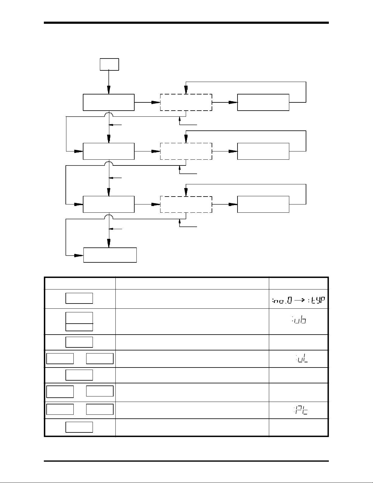
TOSHIBA
8.0 Operating Procedures (Cont'd)
Function #1 Flowchart (Once function is accessed the flowchart is as follows)
A
"vL" register
NEXT
NEXT
NEXT
READ
READ
READ
Display of
Register Contents
[value]"vb" register
NEXT/READ
[value]
NEXT/READ
[value]"Pt" register
NEXT/READ
Display of new
value entered
New [value]
Entered
New [value]
Entered
New [value]
Entered
WRT
WRT
WRT
NEW
VALUE
NEXT
A
Accessing Function #1
Key Action Display
MON
V/F
The inverter must always be placed in the function
mode before accessing any function.
Accesses the voltage boost parameter.
1
READ
or Accesses the maximum voltage frequency parameterNEXT
READ
READ
and Enter new value followed by the WRT key. The unit
WRT
or Accesses the V/f parameter.
READ
READ
Displays the current "vb" setting. :[value]
Displays the current "vL" setting. :[value]
will then display the new current "vL" setting. :[new value]
Displays the current "Pt" setting. :[value]
Note:
Current value of each parameter does not have to be read. Press NEXT key for next parameter.
8 - 2
Page 62

TOSHIBA
8.1 Starting/Stopping - Panel Control
(FORWARD/REVERSE, Run, Coast to Stop, and Emergency Stop)
8.1.1 FORWARD/REVERSE
When wired, make sure the motor rotates in the correct direction selected by the
FORWARD/REVERSE function parameter. If it does not, then reverse two (2)
of the motor's three (3) leads to change the direction. This will ensure the motor's
correct rotation in all possible situations. The FORWARD/REVERSE function is
the first parameter in function #9. Accessing this function is illustrated in the
following table and uses the programming sequence shown below.
First Function Parameters
Function Function Adjustment Factory Error Ref.
No. Name Display Range Set Message Page
Forward/Reverse 0: Reverse 1 8-24
1: Forward
Fault trip saving 0: Cleared when powered off 0 8-24
9
Retry (Auto-reset) 0: Off 0 8-24
1: Data retained when powered off
1: On
Auto-restart 0: Off 0 8-25
1: On
Regen power 0: Off 0 8-25
ride through 1: On
Accessing the FORWARD/REVERSE Function Parameter
Key Action Display
MON
SEL
The inverter must always be placed in the function mode
before accessing any program function.
Accesses the First Function #9 parameters.
9
READ
new value Should a new value be necessary, it can be set by entering the
WRT
MON
Displays the current "F.r." setting. :[value]
new value followed by the WRT command. :[new value]
:[new value] :[new value]
Returns to the inverter's monitor mode . Assumming the
inverter is not running the display will read "0.0".
6
0
WRT
Starting the inverter via the panel requires first entering a
specified run frequency followed by the WRT command.
Example 60Hz
RUN
STOP
Engages the run command. The inverter's output frequency
will "ramp up" to 60Hz, causing the motor to accelerate to its
60Hz speed.
Engages the stop command. The inverter's output frequency
will "ramp down" to 0Hz, causing the motor to decelerate
to a stop.
8 - 3
Page 63

TOSHIBA
8.1.2 Coast to Stop
This inverter is capable of instantly removing power from a rotating motor and
allowing it to coast to a stop. This can be accomplished without removing power
from the inverter. The procedure will override the inverter's normal deceleration
pattern. Activation of the coast to stop function is illustrated below:
Activating the Coast to Stop
Key Action Display
Assume the inverter is operating at 60HZ as shown in the
previous table and is in the monitor mode.
2ND
STOP
8.1.3 Emergency Stop
Key Action Display
STOP
STOP
Engages the COAST to STOP command. The inverter releases
it's control of the motor allowing it to "free wheel" and coast
to a stop.
The emergency stop function can only be used when operating by remote
control. When activated, the inverter can perform the same coast to a stop
function as described in section 8.1.2. In an emergency, valuable time can be
saved by being able to remove power to the motor from the local inverter instead
of from the distant remote control station. Activation of the emergency stop is
illustrated below:
Activating the Emergency Stop
Assume the inverter is operating at 60HZ due to some
type of remote input signal (REMOTE CONTROL).
"EOFF" flashes but the unit continues running. Pressing
STOP once more will activate the stop, however pressing
CLR CLR will cancel the procedure.
Activates the emergency stop function. A fault detection
signal is ouput via terminals FLA, FLB, FLC.
CLR
WRT
Resets the inverter and its fault detection contacts.
The inverter is now ready for normal operation.
Note:
Resetting the inverter from a remote location is accomplished by momentarily
short-circuiting terminals RST to CC. These terminals are located on the
inverter's terminal strip.
8.1.4 Emergency Stop From a Remote Location
A SPST normally closed latch-in type of switch should be connected between
ST-CC. This switch can then be located in a remote location. When the switch is
"toggled" to latch open, the motor will coast to a stop.
CAUTION
Do not toggle this switch ON again until the inverter is
turned OFF (the output frequency reads zero) and the motor
load has stopped rotating.
8 - 4
Page 64

TOSHIBA
8.2 Starting/Stopping-Remote Control
The remote STARTING/STOPPING possibilities are identified in the following
figure and table.
START/STOP Terminals Connections
ST F R CC
F RST
Remote START/STOP Connections Possibilities
Terminal Connection Action
ST-CC F-CC R-CC
OFF ON/OFF ON/OFF The inverter is OFF. OFF will be displayed. If running
when ST-CC is broken the motor will coast to a stop.
ON OFF OFF The inverter is ON but not running.
ON ON OFF The inverter is ON and will run in a FORWARD direction if an
input signal is applied.
ON OFF ON The inverter is ON and will run in a REVERSE direction if an
input signal is applied.
ON ON ON Same as REVERSE connection above.
Note:
ON = short circuit
OFF = open circuit
1) With ST-CC (ON), switching F-CC or R-CC (OFF) will cause the motor to decelerate to
a stop.
2) If input power is turned off (with MCCB) while inverter is running, the motor will coast to
a stop.
3) Acceleration and Deceleration rates are determined by the preset values of 1st
Function #2 (ACC/DEC).
4) When switching from a forward run to a reverse run the motor will decelerate to a stop,
then accelerate in the reverse direction.
CAUTION
Avoid using the input power switch (MCCB) to start and
stop the inverter. Use for an emergency stop only.
8 - 5
Page 65

TOSHIBA
8.3 Frequency Setting - Panel Control
(Digital, Scroll, Jog, 7 Preset Speeds, Pattern Run)
The inverter's panel control is operational when the inverter is in the panel control
mode. Press the CTRL key until the "PANEL CONTROL" LED is on.
8.3.1 Digital
Frequency changes are made by inputting the desired frequency via the
numerical keypad, 0 - 9, followed by the WRT and/or RUN keys. When running,
frequency changes are not made until the WRT and/or RUN key is pressed.
8.3.2 Scroll
Frequency changes are made by inputting the desired frequency via the
"up" and "down" keys. The user can scroll through the frequency range
until a desired frequency is reached. When running, the scrolled frequency
changes are immediate; however, when not running, the RUN key must first be
pressed (see operating frequency setting parameter on page 6-8).
The following procedure illustrates frequency setting:
Frequency Setting
Key Action Display
Power must first be applied to the inverter.
CTRL
6
0
WRT
RUN
1
0
WRT
RUN
WRT
"PANEL CONTROL" LED lights, signifying the inverter is in the panel
control mode.
NOTE: Pressing CTRL again will cause the LED to go off signifying
the inverter is in the remote control mode.
Sets the inverter to 60Hz. Pressing the WRT key enters the data into
the FC file. The display will flash "60" and "FC" alternately indicating the
setting has been made.
Engages the run command. The inverter's output frequency will
accelerate or decelerate to the new set speed designated by "FC".
Pressing 1 0 WRT sets the inverter's new frequency and begins a
deceleration to that frequency. NOTICE the flashing semicolon ":" ,which
signifies the motor is running but that the inverter is not necessarily
displaying the actual output frequency.
Even though the inverter is decelerating, the actual output frequency is
not displayed until the RUN key is pressed.
Pressing the "up" key increases the value displayed. The output
frequency automatically increases. Once 55.4Hz is reached the WRT
key can be pressed. The display will flash "55.4" and "FC" indicating the
setting has been made.
RUN
Note:
Note: Pressing the "down" key will automatically decrease the
inverter's output frequency.
Displays the inverter's actual output frequency. In this case, the actual
output frequency will be the same as that displayed because of the
incremental changes of the "up" and "down" keys.
Operating frequency can be changed during a run.
8 - 6
Page 66

TOSHIBA
8.3.3 Jog
The jog frequency is immediately output regardless of the predetermined
acceleration time. The jog frequency (JOG) and the type of jog stop pattern
(J.StP) must be pre-selected.
Function Parameters
Function Function Adjustment Factory Error Ref.
No. Name Display Range Unit Set Message Page
6 Jog drive frequency 0 to 20 Hz 5 8-23
Jog stop control 0: Deceleration stop
DC injection starting 0.0 to 10 Hz 0 8-27
2ND frequency
1 DC injection voltage 0 to 20 % 0 8-27
DC injection time 0.0 to 5 sec 0 8-27
The following table identifies the STOP pattern and the next table illustrates a
JOG RUN in which the parameters "JOG" and "J.Stp" equal 5Hz and 1,
respectively.
1: Coast stop 0 8-23
2: DC injection stop
Jogging Stop Pattern
Pattern
0 Motor will decelerate to a stop at the rate of DEC1, or DEC2, (dependent upon SEL2).
1 Motor will coast to a stop.
2 Motor will have DC injection applied based upon the DC injection parameters located
in the 2nd Function #1.
Activating the JOG Feature
Key Action Display
MON
2ND 0
RUN
RUN
The inverter must be placed in the monitor mode and stopped before
activating the jog feature.
Engages the jog feature.
Sets a forward run jog.
Sets a reverse run jog.
When held down the inverter will run at the preset jog speed.
When released the motor coasts to a stop (J.StP=1).
CLR
or
STOP
Disables the jog feature. The inverter returns to the monitor mode.
8 - 7
Page 67

TOSHIBA
8.3.4 7 Preset Speeds
The multispeed function provides the user with up to seven preset speed
frequencies. An eighth speed is available when including the remote input
reference signal. These frequencies (Sr1~Sr7) must be pre-selected. By
presetting parameters Sr1~Sr7 the user is able to operate at any of these
speed frequencies, either forward or reverse, simply by using the method
illustrated below:
Multi-Speed Run Frequencies
Function Function Adjustment Factory Error Ref.
No. Name Display Range Unit Set Message Page
1st speed LL to UL setting value Hz 0 8-23
2nd speed LL to UL setting value Hz 0 8-23
6 3rd speed LL to UL setting value Hz 0 8-23
4th speed LL to UL setting value Hz 0 8-23
5th speed LL to UL setting value Hz 0 8-23
6th speed LL to UL setting value Hz 0 8-23
7th speed LL to UL setting value Hz 0 8-23
Note:
All acc/dec times reflect the acc/dec parameter settings which are in effect. These
acc/dec settings are located in 1st Function #2.
Activating the Preset Speed Function
Key Action Display
MON
2ND
The inverter must be placed in the monitor mode and stopped (0.0Hz)
before activating any of the preset speeds.
Engages the preset speed feature. Pressing a key 1-7 selects the
respective preset speed frequency (Sr1~Sr7).
1
thru
7
Sets a forward run
Sets a forward run
RUN
The inverter's output frequency increases to the selected preset
frequency. The attached motor will accelerate to that frequency. [:value]
STOP
The inverter's output frequency decreases to zero (0Hz). The attached
motor will decelerate to a stop.
8 - 8
Page 68

TOSHIBA
8.3.5 Pattern Run
The pattern run enables the user to run up to seven (7) different speeds
automatically, in either forward or reverse directions. It is an extension of the
7 Preset Speeds described in Section 8.3.4. Unlike the Preset Speed Function,
the user can pre-select the length of time in which the inverter will operate at
each frequency (Sr1-Sr7), as well as the acc/dec pattern used to reach each
frequency.
The required preset function parameters are as follows:
1) Actual run frequencies (Sr1~Sr7) are located in 1st Function #6 (Section
8.3.4).
2) The run time for each of these frequencies in the pattern (Pt.1t~Pt.7t) is
located in 2nd Function #8.
3) The particular ACC/DEC drive characteristics to be used, as well as the
run direction (Pt.1~Pt.7) located in 2nd Function #8.
Function Parameters
Function Function Adjustment Factory Error Ref.
No. Name Display Range Unit Set Message Page
Pattern run activation 0: Off 0 8-28
mode 1: Terminal operation
2: Touch pad operation
3: Computer communication
Time unit 0: Seconds 0 8-28
Cycle times 0 to 255 0 8-28
2ND
8 Pattern drive time 0 to 8000 sec 0 8-28
#1 to 7 to min
Pattern drive characteristics 0: Forward run, #1 ACC/DEC
#1 to 7 1: Forward run, #2 ACC/DEC 0 8-28
F/R, ACC/DEC to 2: Reverse run, #1 ACC/DEC
1: Minutes
(255: Infinity operating)
3: Reverse run, #2 ACC/DEC
The following graph shows a sample of a typical pattern run:
(Pt.1)
Pattern 1 acc.
(Pt.2)
Pattern 2 acc.
Forward run
Sr1
Sr2
(Pt.3)
Pattern 3 dec.
(Pt.3)
Pattern 3 acc.
(Pt.4)
Pattern 4 dec.
Pattern 5 dec.
(Pt.5)
Pattern 5 acc.
(Pt.5)
0
Output frequency
Reverse run
Pattern 1
(Pt.1t)
Pattern 2
(Pt.2t)
Pattern 3
(Pt.3t)
8 - 9
Sr3
Sr4
Sr5
Pattern 4 Pattern 5
(Pt.4t)
(Pt.5t)
Time
Page 69

TOSHIBA
8.3.5 Pattern Run (Cont'd)
The run time set for each pattern includes the ACC/DEC time required to reach
that particular run frequency. Therefore, care must be taken when choosing
run times. For example, if the pattern run time is set for 30 seconds and the
acceleration time required to reach the preset frequency is 20 seconds, then
the actual run frequency would last only 10 seconds.
Pattern 1 acc. (Pt.1)
Sr1
:
Output frequency
0
Pattern 1 (Pt.1t)
Activating the Pattern Run
Key Action Display
MON
2ND
The inverter must be placed in the monitor mode and stopped (0.0Hz)
before activating the pattern run.
Engages the pattern run feature.
10
20 30
Time
8
READ
2
Reads the standard factory default setting "off".
Writes the new touchpad operation adjustment "2" to memory.
WRT
MON
CLR
WRT
Takes the inverter out of function setting mode.
Resets the microprocessor.
Engages pattern run.
Notes:
1.) Pressing the STOP key at any time during the pattern run will cause a deceleration to a
stop.
2.) Pressing 2ND and then STOP will cause a coast to a stop.
3.) Resuming the pattern run is accomplished by pressing RUN, however be aware that the
run proceeds from the point of interruption unless 2ND is pressed before RUN is pressed.
4.) In order to deactivate the pattern run function the above procedure should be followed in
the same order except that 0 should be stored for P.SEL at step 4.
8 - 10
Page 70

TOSHIBA
8.3.5 Pattern Run (Cont'd)
Use the following procedure to monitor a pattern run. For this example the
inverter is running in pattern 1 at 10Hz and there are 12.3 minutes remaining
in pattern 1.
Monitoring During a Pattern Run
Key Action Display
A pattern run frequency is displayed
NEXT
NEXT
NEXT
NEXT
MON
MON
Displays current pattern number
Displays balance of time remaining in the current run pattern
Displays remaining patterns
Displays current forward/reverse status. Continued pressing of the
NEXT key provides monitoring of the inverters status information.
The items appear in the sequence listed in section 7.5.1
Returns to displaying the current patterned run frequency.
or
8 - 11
Page 71

TOSHIBA
8.4 Frequency Setting - Remote Control
JP1 JP2
I V 10V 5V
1
The inverter's remote control is operational when the inverter is in the remote control
mode. The "PANEL CONTROL" LED is off. All frequency setting input signals (0-5Vdc,
0-10Vdc, 0-20mA, 4-20mA, 3k ohm pot, JOG, and Preset Speeds) are applied to the
drive through the terminal block which is located on the control/driver printed wiring board
(see page 4-11 for terminal block and jumper details).
8.4.1 Proportional/Follower Input Signals
The following table illustrates the connections required for receiving the different
analog input signals.
Terminal/Jumper Connections for Input Reference Signals
FunctionTerminal Connections
NO CONNECTIONS, JP1 & JP2 should be
set as shown for normal panel operation.
Required for normal panel operation.
I V 10V 5V
2
I V
3
10V 5V
N/A
I V
4
I V
5
10V 5V
10V 5V
RR IV CCPP
+
RR IV CCPP
+
PP
RR IV CC
PP
RR IV CC
0~5Vdc
0~5Vdc
0~10Vdc
3k ohm
_
_
N/A
PP
10V 5VI V
6
RR IV CC
0~20mA
(4~20mA)
N/A
Required for standard 0~5Vdc input
reference signal. Function No. 5
RR terminal priority should be set to
1 "on" when using this feature.
See Ref. page 8-23.
Required for standard 0~10Vdc input
reference signal. Function No. 5
RR terminal priority should be set to
1 "on" when using this feature.
See Ref. page 8-23.
Required when using a 3k ohm pot.
A 1K to 10K ohm pot can also be
used but the pot adjustments will be
more critical.
Required for standard 0~5Vdc input
reference signal. Function No. 5
RR terminal priority should be set to
the normal setting of 0 "off" when
inputting a signal to the IV terminal.
See Ref. page 8-23.
Required for standard 0~20mA,
4~20mA input reference signal.
Function No. 5 RR terminal priority
should be set to the normal setting
of 0 "off" when inputting a signal to
the IV terminal. See Ref. page 8-23.
PP
10V 5VI V
6*
RR IV CC
SW
0~20mA
(4~20mA)
When switch is closed (ON), the
remote pot will override the
0~20/4~20mA input reference
signal. Function No. 5 RR terminal
priority should be set to the normal
setting of 0 "off".
8 - 12
Page 72

TOSHIBA
8.4.2 Terminal IV
Terminal IV ( ) is a special terminal which is used in conjunction with
1st Function key #5 to output exact frequencies based upon specific input
reference signals. These output frequencies do not necessarily have a one-toone ratio with the input reference signals. The following graphs and examples
illustrate how this function can be adjusted.
Function Function Adjustment Factory Error Ref.
No. Name Display Range Unit Set Message Page
IV-ref. setting point #1 0 to 100 % 20 8-23
5 #1 output frequency 0 to Max. frequency Hz 0 8-23
IV-ref. setting point #2 0 to 100 % 100 8-23
#2 output frequency 0 to Max. frequency Hz 80 8-23
IV CC
Function Parameters
RR terminal priority 0: IV terminal input "on" 0 8-23
Max Frequency
(FH) and/or (F-P2)
0Hz (F-P1)
Example: Application requiring the following output characteristics is shown below:
FH 80
60(F-P2)
20(F-P1)
In the above graph the inverter has no output frequency until the input signal has reached 35%
of its maximum. This is due to the linear characteristics of the IV Function. Also notice that the
maximum frequency is reached before 100% of the input signal is applied.
Hz
Hz
Factory Setting
35% 50%
(P1)
1: RR terminal input "on"
% INPUT SIGNAL
P1=50% of maximum input signal
F-P1=20Hz
P2=80% of maximum input signal
F-P2=60Hz
FH=80Hz
80%
(P2)
95%100%
Input Signal
IV
IV
REF
REF
0%
0V
0mA
0V
0V
20%
4mA
100%
5Vdc
20mAdc
5Vdc
10Vdc
JP1=V
JP1=I
JP2=5V
JP2=10V
Note:
In most cases the value of UL is less than FH.The value of UL cannot be greater than FH.
Hz
FH 80
(F-P2) 60
(F-P1)40
20
40%(P1) 80%(P2) 100%0
In the above graph the inverter has an output frequency of
20Hz even with a 0% input signal. Also notice that the
maximum output frequency is never reached unless the input
signal goes above 100%. (i.e. a 7Vdc input signal is considered a 140% input signal when using a 0~5Vdc input.
Hz
FH
(F-P2) 60
(F-P1) 40
20
0(P2)
In the above graph the inverter has a negative output. In
other words, as the input signal increases the output
frequency decreases. Notice that at 0% and 100% input
the inverter outputs 60Hz and 0Hz, respectively.
33%
100%(P1)66%
8 - 13
Input
Signal
Page 73

TOSHIBA
8.4.3 Jog
The jogging frequency is immediately output when the remote JOG is activated.
The functions "JOG" and "J.StP" must be preset. Use 1st Function #6 key to
access these functions. In addition, the JOG(SS2) terminal must be set for
"JOG". This is accomplished by setting the function parameter "1.tb" to 1 or 3.
Use 1st Function #8 key to access this function. The terminal connections,
function parameters, and input/output graph are all shown below:
Function Parameters
Function Function Adjustment Factory Error Ref.
No. Name Display Range Unit Set Message Page
Jog drive frequency 0 to 20 Hz 5 8-23
6 Jog stop control 0: Deceleration
Multifunction input 0: SS2, SS3
8 1: JOG, SS3 2 8-24
1: Coast stop Hz 0 8-23
2: DC injection stop
2: SS2, AD2
3: JOG, AD2
ST F R CC SS1
JOG
(SS2)
AD2
(SS3)
Terminal Connections Required
For Remote Jog
Hz
Output
Frequency
ST F R
Jogging run
frequency (JOG)
set via panel
Run frequency
setting from
terminals
Time
ST-CC
F-CC
R-CC
PP, RR, IV
Terminal inputs
JOG-CC
Notes:
1) A jogging run cannot be engaged by closing the JOG switch during a run.
2) The inverter will decelerate at the selected rate during: deceleration stop, coast
to stop, injection stop.
3) F-CC must be broken for DC injection to be applied; breaking only JOG(SS2)-CC
allows the inverter to accept other input signals and is not a "true" off.
4) See table on next page for terminal inputs and actions.
8 - 14
Page 74

8.4.3 Jog (Cont'd)
Terminal inputs and actions
Terminal Connections Action
ST F R
JOG
(SS2)
ON ON OFF OFF Jogging Stop
ON ON OFF ON Reverse Jogging Run
ON ON ON OFF Forward Jogging Run
ON ON ON ON Reverse Jogging Run
8.4.4 7 Preset Speeds
For remote operation the following preset functions, terminals, and chart must
be used. Follow the same procedure as in section 8.3.4 for setting the preset
speed frequencies.
TOSHIBA
ST F R CC SS1
Terminal Connections Required for
Remote Preset Speeds
F SS1 SS2 SS3
RST
Terminals SS2 and SS3 have dual functions, however only one function can be
used at a time. Enabling the other functions (JOG, AD2) disables functions
SS2 and SS3, thus limiting the number of accessable preset frequencies.
The following chart identifies the functions of the 3 terminals (SS1, SS2, SS3)
and their corresponding accessable preset frequencies.
Terminal Inputs
Setting selection Terminal Selection 1.tb Frequency setting
of parameter1.tb AD2/SS3-CC JOG/SS2-CC SS1-CC via terminals
OFF OFF OFF Operating frequency set via PP, IV, RR terminals
OFF OFF ON 1st operating frequency
0 OFF ON OFF 2nd operating frequency
(SS2) OFF ON ON 3rd operating frequency
(SS3) ON OFF OFF 4th operating frequency
ON OFF ON 5th operating frequency
ON ON OFF 6th operating frequency
ON ON ON 7th operating frequency
OFF OFF OFF Operating frequency set via PP, IV, RR terminals
1 OFF ON OFF Jogging
(JOG) OFF OFF ON 1st operating frequency
(SS3) ON OFF OFF 2nd operating frequency
ON OFF ON 3rd operating frequency
2 *ON/OFF OFF OFF Operating frequency set via PP, IV, RR terminals
(SS2) *ON/OFF OFF ON 1st operating frequency
(AD2) *ON/OFF ON OFF 2nd operating frequency
*ON/OFF ON ON 3rd operating frequency
3 *ON/OFF OFF OFF Operating frequency set via PP, IV, RR terminals
(JOG) *ON/OFF ON OFF Jogging
(AD2) *ON/OFF OFF ON 1st operating frequency
JOG
(SS2)
AD2
(SS3)
Note:
When "1.tb" (accessible by TB KEY #8) is set to 2 or 3 the AD2 function is activated. This
function enables the user to remotely switch between the ACC/DEC patterns 1 and 2, provided
SEL2=0. If SEL2=1 then the only pattern available is given by ACC2, DEC2, Pt.2. With AD2-CC
terminals shorted (ON) all ACC/DEC patterns are run using the settings of the ACC2, DEC2, Pt.2
parameters.
8 - 15
Page 75

TOSHIBA
8.5 Output Signals
The inverter provides terminals for outputting signals to external components. A number
of selectable "operating" output signals, as well as "fault" output signals, are available.
These output signal terminals are located on the terminal board. The terminals and type
of selections available are shown below.
Output Terminals
RCH
(UL)
LOW
(LL)
FLA FLB FLC
8.5.1 Selectable Outputs
Function Parameters
Function Function Adjustment Factory Error Ref.
No. Name Display Range Unit Set Message Page
8 Multifunction output 0: LL, UL
Low speed detection 0.0 to Max. frequency Hz 0.5 8-28
Speed reach selection 0: Complete ACC/DEC 0 8-28
2ND 1: Frequency reach reference
3
Speed reach detection 2.5 to 25 Hz 2.5 8-28
range
Speed reach reference 0.0 to Max. frequency Hz 0 8-28
1: LOW, UL 3 8-24
2: LL, RCH
3: LOW, RCH
Terminal Output Signal Selections
Setting on 0.tb Function
0 LL, UL (for lower limit and upper limit frequency signal)
1 LOW, UL (for low speed and upper limit frequency signal)
2 LL, RCH (for lower limit frequency and speed reach signals)
3 LOW, RCH (for low speed and speed reach signals)
Selectable function output signals (open-collector with 50mAdc~24Vdc ratings)
Terminal Function
LL
UL
LOW
RCH
Outputs a signal when frequency is = or > the LL value.
Outputs a signal when frequency is = UL value.
Outputs a signal when frequency is = or > the LOW SPEED DETECTION VALUE "LF".
Outputs a signal based upon the selection of the RCH parameters rCH, rrCH, FrCH.
Upper/lower limit frequency signal output Low speed/speed reach signal output with rCH=0
Hz
UL
Output
frequency
LL
Output signals:
Across
UL-P24
Across
LL-P24
TIME
ON
TIME
ON
TIME
Hz
Output
frequency
LOW
Output signals:
Across
LOW-P24
Across
RCH-P24
ON
ON ON
TIME
TIME
TIME
8 - 16
Page 76

8.5.1 Selectable Outputs (Cont'd)
Reach Selection
rCH function Action
0 Outputs a signal when an acc/dec is complete and inverter is at a constant
frequency. Note: Output signal is off only during an ACC or DEC.
1 Outputs a signal when the inverter's output frequency is within a range of
frequencies specified by parameters FrCH and rrCH.
Low speed/speed reach signal output with rCH=1
Hz
+rrCH
FrCH
-rrCH
Output frequency
LOW
TOSHIBA
TIME
Across LOW-P24
Across RCH-P24
Output signals
ON
ON
ON
TIME
TIME
8.5.2 Inverter to Relay/PC Connections
Terminals RCH (UL) and LOW (LL) of the control circuit terminal block are open
collector outputs which float in an open state. When the designated frequency
has been reached the terminals can sink 24Vdc at 50mAdc to ground. P24
supplies 24Vdc through the relay coils to the RCH (UL) and LOW (LL) terminals
for relay activation. Connections are shown below for either relay logic or
programmable controller inputs. Notice that there is no difference in the circuits
except how the relay outputs are utilized.
Inverter-to-relay connections Inverter-to-programmable controller connections
P24
RCH
(UL)
LOW
(LL)
P24
RCH
(UL)
LOW
(LL)
Note:
Ry Ry
Relay Logic Outputs
Ry Ry
Dry Contact Outputs to PC
(Consult factory for specific applications)
When an output frequency fluctuates in the vicinity of a frequency to be reached, the reach signal
may alternately turn on and off because of the lack of hysteresis in the reach signal.
8 - 17
Page 77

TOSHIBA
8.5.3 Fault-Detection Output Terminals
When any of the inverter's system protection features are activated and the
inverter trips (see list of probable causes in section 7.5.2), the cause of the
problem will be displayed and the fault-detection relay will be activated. This will
cause the contacts associated with the Fault-Detection Output Terminals to
change state. The fault-detection terminals FLA, FLB, and FLC are provided as
a NO, NC form C contact rated for a 250Vac/30Vdc 2A output.
Internal To
Inverter
8.5.4 Resetting After a Trip
The inverter can be reset after a trip by two methods:
1) Pressing the CLR and WRT keys on the operating panel resets the
inverter locally.
2) Momentarily closing a normally open contact between terminals RST and
COM resets the inverter remotely.
When the inverter trips due to an emergency stop or the
activation of one or more of its protective functions, the
CAUTION
cause of the fault must be corrected before resetting the
inverter. A forced restart with out prior fault correction
measures could damage the inverter and connected devices.
NO
Terminal Connections
NC
FLCFLBFLA
FL
8 - 18
Page 78

8.6 Calibration of Remote Meters (FM & AM)
Many times an application requires that a frequency meter or ammeter be remotely
located. With the G2+ inverter, calibration of the remote meters is very easy.
Attachment of the meter between its appropriate terminals is the only wiring necessary.
Actual calibrating is performed with the keypad.
8.6.1 Frequency Meter (FM) Connection and Procedures
Terminal Connection (FM)
TOSHIBA
CCFM
+ -
Zero adjust
screw
Calibration Procedure (FM)
Key Action Display
For this example the inverter is running at 60Hz, and in the monitor mode.
Frequency Meter
(1mAdc ammeter or
7.5Vdc voltmeter)
2ND
MON
RUN
or
WRT
Engages the "FM" calibration mode
Display indicates the inverter's output frequency
Adjusts the frequency value of the analog meter. Press the "up" or
"down" key until the meter value equals the displayed inverter value.
Calibration of "FM" meter is complete
:
:
MON
Notes:
Returns to the actual frequency display.
1) The adjustment operation can be interrupted at any time by pressing the STOP
key.
2) Although the above example shows calibration of the remote meter at a running
frequency of 60Hz; better resolution of the meter can be obtained if the inverter
is running at the maximum frequency. Disconnect the motor load for FM
calibration at the highest frequency.
8 - 19
Page 79

TOSHIBA
8.6.2 Ammeter (AM) Connection and Procedures
Terminal Connection (AM)
CCAM
+ -
Ammeter
Key Action Display
Adjustments should be made during a run. For this example the inverter
is running at 60Hz, and in the monitor mode.
2ND
Engages the "FM" calibration mode.
Zero adjust
screw
Calibration Procedure (AM)
Frequency Meter
(1mAdc ammeter or
7.5Vdc voltmeter)
:
MON
NEXT
RUN
Engages the "AM" calibration mode.
Display indicates the output current values [value]
:
:
or
WRT
MON
Notes:
Adjusts the current value of the analog meter. Press the "up" [value]
or "down" key until the meter value equals the displayed inverter
value.
Calibration of "AM" meter is complete
Returns to actual frequency display
The calibration procedure can be interrupted at any time by pressing the STOP key.
:
:
8 - 20
Page 80

8.7 Operating Functions - Descriptions and Examples
Some features not previously introduced, but just as important, are found in this section
along with all of the other features and functions.
FIRST FUNCTIONS
Selects standard setting mode and sets maximum safe frequency (FH) for motor
being run.
FMAX
TOSHIBA
0
V/F
1
ACC/DEC
2
UL/LL
3
VOLTAGE BOOST - Increases the start-up torque of the motor being run.
AUTO TORQUE BOOST - Automatically increases the percentage of voltage boost
when starting torque requirements are abnormally high.
FREQUENCY at MAXIMUM VOLTAGE - Sets the frequency at which the output voltage
is 100%.
V/f PATTERN - Selects a constant or variable torque pattern.
ACC1, DEC1, Pt1/ACC2, DEC2, Pt2 - Sets the times required to ACC/DEC between
0Hz and the maximum frequency value FH. Also selects the pattern by which the
ACC/DEC times are run (see section 5.7)
SEL2 - Selects which ACC/DEC/Pt will be used (#1 or #2).
Note: ACC/DEC times are the times required to go between 0Hz and the maximum
frequency FH.
UPPER LIMIT - Sets the upper frequency limit. The inverter will never operate above
this upper limit.
Note: The value of FH must always be equal to or greater than the value of UL.
LOWER LIMIT - Sets the lower frequency limit. The inverter will never operate below
this lower limit.
Application Example - The inverter is used to control a 50Hz motor which has a safe
operating frequency of 80Hz. This motor drives a conveyor belt which must run
according to the following specifications: "tyP=1" "FH=80"
ACC/DEC times are the times required to go between 0Hz and FH.
1) For this example, a VOLTAGE BOOST OF 10% is needed to move the
conveyor at low start-up speeds: "ub=10"
2) Although a 50Hz motor is used, specifications require 100% output voltage
at 60Hz: "uL=60"
3) Conveyor belt systems require a constant torque: "Pt=0"
4) When running the conveyor the inverter must run no faster than 60Hz and
no slower than 20Hz: "LL=20" "UL=60"
5) The maximum acceleration and deceleration between 20Hz and 60Hz must
be 30 seconds and 10 seconds respectively. A linear pattern is required.
FH=80
60
Choosing
Acceleration
Hz
40Hz
20
0
30 Sec.
10 Sec.
Time
8 - 21
Page 81

TOSHIBA
8.7 Operating Functions - Descriptions and Examples (Cont'd)
100
Because ACC/DEC times are based upon the change in Hz/SEC the following
formula must be used.
FH/Frequency range X (ACC/DEC time of frequency range) = ACC/DEC
ACC1 = 80Hz : (60-20Hz) X 30 sec. = 60 sec. ACC1=60
DEC1 = 80Hz : (60-20Hz) X 10 sec. = 20 sec. DEC1=20
Note:
Specifications required only one ACC/DEC rate, therefore ACC2/DEC2/Pt2
settings were not needed: SEL2=0
Setting ACC2/DEC2/Pt2 would be suggested if a different pattern was required.
Switching between the two patterns would then simply require switching between
SEL2=0 and SEL2=1.
100
% Voltage
LL
ACC
DEC
OL
4
% Voltage
10
Hz
60
10 sec. 60 sec.
10 sec.
FACTORY SETTINGS EXAMPLE SETTINGS
80 UL, FH
ACC
DEC
20
LL
20 sec.
50 60
UL
FH
OVERLOAD PROTECTION - Sets the thermal overload detection level to match the
ratings and characteristics of the motor being used (10% to 100% of rated output
current). The inverter will run continuously at 110% of the overload protection (i.e.
Setting: inverter rated current = 50amps, overload level set at 60% leads to set rated
current = 50 X 60% = 30amps and continuous set rated current = 30 X 110% = 33amps).
STALL PROTECTION - Sets the activation level of the stall protection function (90% to
150% of rated output current). When the stall level is reached the inverter will begin
stalling by lowering the frequency and voltage to prevent overcurrent tripping. Once a
soft stall has occurred the output current will be clocked. If output current is not reduced
within a specified time a fault will occur. (See section 3.0 for ratings and section 7.5.2 for
fault codes.)
Note:
Instantaneous trip current limits are factory set and are dependent upon inverter
size as well as the motor ripple current. The inverter's soft stall function is
particularly effective in situations where load current decreases as revolution
speed decreases (i.e. wind and hydraulic power machinery).
Hz
100%
60%
Overload
detection level
FOR STANDARD MOTORS FOR VF MOTORS
OVERLOAD DETECTION CURVE - Selects an overload detection curve for a standard
motor or a variable frequency motor, with and without soft stall.
100%
60%
Overload
detection level
00
FMAX45Hz FMAX
FrequencyFrequency
8 - 22
Page 82

8.7 Operating Functions - Descriptions and Examples (Cont'd)
Note:
"100% of overload detection level" refers to the value of the inverter's rated
output current.
Setting of SEL4
Setting of SEL4 Function
0 Standard motor without soft stall function
1 Standard motor with soft stall function
2 VF motor without soft stall function
3 VF motor with soft stall function
Application Example - A 3HP 230V G2+ inverter is used to drive a 2HP 230V motor
rated at 6.8 amps full load. Because the inverter is rated at 10 amps there is a danger
of burning up the motor. By using the overload features of the inverter the output
current can be limited and the stall protection level adjusted accordingly.
TOSHIBA
REF
5
JOG
6
IV - REFERENCE POINT #1 - Sets the % of the terminal IV input signal which is used
to reference the output frequency designated by F-P1.
#1 OUTPUT FREQUENCY [F-P1] - Sets the output frequency used for reference
point #1.
IV - REFERENCE POINT #2 - Same as reference point #1, except makes reference to
F-P2.
#2 OUTPUT FREQUENCY [F-P2] - Sets the output frequency used for reference
point #2.
SEE SECTION 8.4.2 FOR EXAMPLES.
RR TERMINAL PRIORITY - Activates the terminal into which the analog reference
signal will be input.
JOGGING DRIVE FREQUENCY - Sets the frequency at which the inverter will operate
while in the JOG mode. Used for moving small increments when precise-positioning
of motor-driven equipment is required.
JOGGING STOP CONTROL - Selects between three methods of stopping during a
jog run.
1ST SPEED ~ 7TH SPEED - Sets the frequencies used in the 7 speed run and the
patterned run.
JMP
7
SEE SECTION 8.4.3 FOR DETAILS.
JUMP FREQUENCY POINT #1 AND BAND #1 - Sets the frequency range to be skipped
when running a motor. This function is used when the resonance of the loaded machine
must be avoided. Jump frequency ranges 2 and 3 are also available. See jump frequency
graph on page 8-24.
8 - 23
Page 83

TOSHIBA
8.7 Operating Functions - Descriptions and Examples (Cont'd)
Jump frequency graph
TB
8
FJ3
FJ2
Output frequency
FJ1 ±bfJ1
Frequency setting signal
±bfJ2
±bfJ3
Note:
Frequency jumps cannot be used during preset acceleration/deceleration runs.
When a frequency setting signal reaches the jump frequency range, the
inverter's output frequency will remain fixed while the display frequency will
continue to rise or fall. Once the input signal reaches the opposite end of the
jump range the inverter will jump up or down to the allowable frequency.
MULTIFUNCTION INPUT - Selects the way in which terminals JOG(SS2) and
AD2(SS3) are to be used.
SEE SECTION 8.4.3 and 8.4.4 FOR DETAILS.
MULTIFUNCTION OUTPUT - Selects the way in which terminals RCH(UL) and
LOW(LL) are to be used.
SEE SECTIONS 8.5.1 and 8.5.2 FOR DETAILS.
SEL
9
FORWARD/REVERSE - Selects between a forward and reverse run.
FAULT TRIP SAVING - Selects between saving or not saving the fault code
information when power is removed from the inverter. When this function is set to
save fault data (active) the auto reset function will become inactive.
AUTO-RESET - When selected, the inverter will automatically try to restart when a
protective function activates an inverter fault trip (unless the fault trip saving function
is activated).
Setting on retry Function
0 OFF - If the inverter trips, the system will retain the tripped
condition but will not try to restart.
1 ON - If the inverter trips, the system will automatically try to
restart but only under the following conditions (see next page
for chart of auto-reset conditions).
8 - 24
Page 84

TOSHIBA
8.7 Operating Functions - Descriptions and Examples (Cont'd)
Auto Reset Conditions
Cause of fault Reset Process Reset Failure Conditions
Overcurrent Tries to restart 5 times in succession The reset process follows this chart
Overload 1st reset: 1 sec. after problem occurs. unless a fault, other than those listed,
2nd reset: 2 sec. after initial restart. occurs. If this happens the inverter will
3rd reset: 4 sec. after 2nd restart try. not try to reset.
4th reset: 8 sec. after 3rd restart try.
5th reset: 16 sec. after 4th restart try.
Overvoltage Trips, displays OP, sets fault relay until
overvoltage condition is removed.
Fault relay will be cleared after reset.
Note:
The cause of the fault(s) could be from an instantaneous power interrupt.
While preparing for a reset, the auto-reset function causes the fault code "0.0" to be
displayed alternately on the monitor display. Fault-detection signals are not output during
the inverter's reset process. If the cause of the failure has not been corrected, then the
intervals before each attempted reset will be prolonged. See above chart.
If the load exhibits an extremely large amount of inertia (WK)2, automatic restart using
the procedure described above may not work.
Note:
No restart is tried when any of the following messages is displayed on the inverter's
monitor display:
"OCA" Overcurrent (transistor short-circuited at start-up)
"OCL" Overcurrent (load end short-circuit at start-up)
"OCr" Overcurrent (overcurrent through the regenerative discharge resistor)
"EF" Ground fault
"E" Emergency stop
"EEP" E2PROM failure
CAUTION
AUTO-RESTART - When selected, the inverter will automatically restart into a freerotating motor. This restart will occur only after an instantaneous power interruption has
occurred. The function allows the inverter to sample the speed of the free-rotating motor
during the interruptions and output a matching frequency when power is reapplied. This
assures smooth restarts of a free-running motor when an instantaneous power loss has
occurred such as when the system is switched from a commercial bypass run to an
inverter run.
Note:
With ArSt=0, the inverter will restart at 0Hz and increase up to the initial running
frequency. With ArSt=1, the inverter will restart at the running frequency of the motor
and will increase up to the initial frequency of the inverter.
Before using the inverter's retry (auto-reset) function, check
to be certain that the auto-reset procedure will not damage
or otherwise cause problems for the load machine system when the inverter's retry operations are being
executed.
REGENERATION POWER RIDE THROUGH CONTROL - Uses regenerative energy
to extend the inverter's power ride through capability during momentary power dropouts.
8 - 25
Page 85

TOSHIBA
8.7 Operating Functions - Descriptions and Examples (Cont'd)
2ND
FMAX
0
(Start frequency F-St can be set @ 0 to 10Hz)
Maximum
frequency
Frequency
F-St
0 100%
SECOND FUNCTIONS
START-UP FREQUENCY - Sets the frequency at which the inverter will begin operating.
In the panel control setting mode the frequency display will change as the "up" and
"down" keys are pressed. However, an actual output does not occur until the startup frequency is reached. In the terminal input mode the display will remain at zero until
the start-up frequency is reached. This function, along with the voltage boost function,
enables the user to obtain an optimum voltage boost level. See figures below.
Start-Up Frequency
Frequency setting signal Output frequency
Start-Up Frequency with Voltage Boost
100%
30%
Output voltage
boost
Voltage
F-St0
Hz
RUN FREQUENCY - Selects a frequency to initiate inverter run/stop control.
RUN FREQUENCY HYSTERESIS - Used to offset inverter run frequency.
When the frequency reference signal reaches the Frun + Fhys point, the drive will ramp
the motor to that speed. The inverter will continue to follow the reference signal until it
falls below the Frun - Fhys at which time the drive will ramp the motor to a stop. See
figure below.
FH
Frun + Fhys
Frun
Frun - Fhys
Output Frequency
0
0% 100%
Reference Signal
Stop
Start
% Frequency
2ND
V/F
1
DC INJECTION START FREQUENCY - Specifies the frequency at which DC injection
is applied to a motor during a decelerating stop. Used for precise positioning (inching)
of the motor driven equipment.
DC INJECTION VOLTAGE - Specifies the percent of voltage applied during the
DC injection.
DC INJECTION TIME - Specifies the length of time the DC voltage applied.
SEE SECTION 5.10.
8 - 26
Page 86

8.7 Operating Functions - Descriptions and Examples (Cont'd)
TOSHIBA
2ND
ACC/DEC
2
2ND
UL/LL
3
2ND
DISPLAY FREQUENCY SCALER - Used to display revolution speed and linear speed.
SEE SECTION 5.8 FOR EXAMPLE.
LOW SPEED DETECTION - Outputs a signal when the inverter's output frequency is
greater than or equal to the selected low speed detection frequency.
SPEED REACH SELECTION - Selects the option to output a signal when an
ACC/DEC is complete or when the inverter's output frequency is within a selected
range. The range is selected by the following two functions.
SPEED REACH DETECTION RANGE - Specifies a range of frequencies, above and
below the speed reach reference frequency, which when detected will output a signal.
SPEED REACH REFERENCE - Specifies the speed reach detection frequency. When
the inverters output frequency is within the range specified by the Speed reach reference
(± speed reach accuracy), a signal will be output.
SEE SECTION 8.5 FOR EXAMPLES.
OUTPUT VOLTAGE ADJUSTMENT - Specifies the percent of input voltage which is
seen as the inverter's output voltage.
OL
informs the inverter system whether or not a dynamic braking resistor (DBR) is used.
4
2ND
REF
REGENERATIVE BRAKING SELECTION - Selection of the appropriate parameter
If (yes), then whether or not there is overload detection.
LENGTHENED DECELERATION (Auto-deceleration on the : Pb=0) - Automatically
lengthens the deceleration time to prevent over-voltage trips.
TG/PG * or PID - Informs the inverter of either tach generator (TG)/pulse generator (PG)
feedback, proportional/integral/differential (PID) control, or nothing at all.
PROPORTIONAL GAIN - Sets the gain of the TG/PG or PID controlled input signal.
5
INTEGRATION GAIN - Adjusts the period of integration when comparing the set point
to the feed back signal.
DIFFERENTIAL GAIN - Stabilizes the system when hunting occurs.
LAG-TIME GAIN - Adjusts the time of response when a change in the feed back signal
is seen.
TG/PG FEEDBACK SELECTION - Selects the type of speed feedback control signal to
be used.
PG FEEDBACK GAIN (Coefficient of TG/PG conversion) - Adjusts the drive to respond
correctly to the external pulse generator.
* TG/PG requires the use of multi-option board.
8 - 27
Page 87

TOSHIBA
8.7 Operating Functions - Descriptions and Examples (Cont'd)
2ND
PWM CARRIER FREQUENCY - Selects the inverter's PWM carrier frequency.
JOG
6
2ND
boards binary input.
JMP
7
2ND
OPTION TERMINAL SELECTION * - Used in conjunction with multi-function option
INVERTER NUMBER * - Allows an inverter identification number to be assigned to the
unit.
BAUD RATE * - Selects baud rate.
SEE SECTION 5.4.
RS232C COMMUNICATION DATA BITS * - Used to select the number of RS232C
communication bits for host computer control.
PARITY AND STOP BITS * - Used to select the parity check and stop bits for host
computer control.
INVERTER TO LINE TRANSFER SIGNAL * - Allows a motor load to be transfered
between the inverter and line power by a signal to the inverter.
PATTERN RUN ACTIVATION MODE - Used to activate a pattern run by determining
where the start command will be taken from.
TB
8
2ND
SEL
9
PATTERN TIME SELECTION - Sets the run time of each individual preset speed to
either seconds or minutes.
PATTERN REPEATABILITY - determines how many times the pattern run will repeat
itself.
PATTERN DRIVE TIME (#1~#7) - Sets the run time of each individual preset speed
frequency (SR1~SR7) to be used in the patterned run.
PATTERN DRIVE CHARACTERISTIC (#1~#7) - Selects the type of run for reach preset speed frequency. The selection can be a forward or reverse run, using either
ACC/DEC #1 or ACC/DEC #2.
COMMAND MODE SELECTION - Determines where the inverter can be started and
stopped; (via the touch-pad, terminal strip, or the host computer).
FREQUENCY REFERENCE SETTING MODE SELECTION - Determines where the
frequency signal is accepted by the inverter; (via the touch-pad, terminal strip, or the
host computer).
PARAMETER SETTING MODE SELECTION - Determines where the parameters can
be programmed; (via the touch-pad, or the host computer).
SEE PAGES 8-29 AND 8-30 FOR EXAMPLES
* These parameters require the use of multi-option board
8 - 28
Page 88

TOSHIBA
8.7 Operating Functions - Descriptions and Examples (Cont'd)
The three (3) parameters in 2nd Function 9 on the G2+ allow the user to do a number
of different setups. The access to the inverter can be totally locked out, or select
functions can be locked out. By using these three parameters the inverter can be
programmed to function in a number of different ways.
The following example shows how to Start-Stop the unit via the touch-pad only and
have the frequency set by an external source only by changes to the paramenters
located in 2nd function 9.
Key Action Display
MON
2ND
9
READ
2
WRT
NEXT
READ
1
WRT
The inverter must always be placed in the function mode before
accessing any function.
When this key is pressed the inverter is placed into the second
function files.
When this key is pressed the inverter is placed into the second
function file number 9.
When this key is pressed the standard factory adjustment range
setting of 7 is displayed.
When the keys 2 and WRT are pressed in order then the factory
adjustment range setting of 2 is written into memory replacing the
factory setting of 7.
When this key is pressed the second menu item under the 2nd 9
functions is displayed.
When this key is pressed the standard factory adjustment range
setting of 7 is displayed.
When the keys 1 and WRT are pressed in order then the factory
adjustment range setting of 1 is written into memory replacing the
factory setting of 7.
MON
Note:
Returns the inverter to the original monitor mode.
This setup accepts an external signal (4-20 mA, 0-5 VDC, & etc. ) through the terminal strip
and allows the user to start and stop the unit via the touch-pad.
8 - 29
Page 89

TOSHIBA
8.7 Operating Functions - Descriptions and Examples (Cont'd)
The following example shows how to Start-Stop the unit remotely and have the
frequency set via the touch-pad. To do this, set the paramenters on 2nd function 9
as follows.
Key Action Display
MON
2ND
9
READ
1
WRT
NEXT
READ
2
WRT
The inverter must always be placed in the function mode before
accessing any function.
When this key is pressed the inverter is placed into the second
function files.
When this key is pressed the inverter is placed into the second
function file number 9.
When this key is pressed the standard factory adjustment range
setting of 7 is displayed.
When the keys 1 and WRT are pressed in order then the factory
adjustment range setting of 1 is written into memory replacing the
factory setting of 7.
When this key is pressed the second menu item under the 2nd 9
functions is displayed.
When this key is pressed the standard factory adjustment range
setting of 7 is displayed.
When the keys 2 and WRT are pressed in order then the factory
adjustment range setting of 2 is written into memory replacing the
factory setting of 7.
MON
Returns the inverter to the original monitor mode.
In order to run the inverter, simply enter the desired frequency followed by the WRT key.
The remote start/stop switch will be put between F (forward) or R (reverse) and CC
terminals on the terminal strip. Closing the connection will make the inverter run,
opening the connection will make the inverter decelerate to a stop at the programmed
deceleration time.
8 - 30
Page 90

9.0 Spare Parts List/After Sales Service
9.1 Requesting After Sales Service
When requesting after-sales service, report the contents of the following PROBLEM
INFORMATION SHEET, which will help repair the system quickly.
Problem Information Sheet
Item
Customer's name
Refer to Person in charge
Address
Telephone No.
Inverter Model No.
spec. Serial No.
Test No.
Delivery date
Time in service
Date when problem arose
Use
Motor rating Poles, Hp, V, Hz.
Made by Toshiba? Made by another company?
New? Number of units?
Alternate? Continuous?
Status of Indoor? Outdoor? Temperature range?
Use Ambient Humidity:
condition Dust composition and size:
Presence of salt and extent of corrosion from it:
Vibrations, in micrometers:
Presence of corrosive gas:
Availability of air conditioning:
Number of phases:
Voltage between L1 phase and L2 phase:
Power Voltage between L2 phase and L3 phase:
source Voltage between L3 phase and L1 phase:
Number of Hz:
Problem occurred hours after motor had been started. Motor has
been stopped for hours.
Phenome- State of Problem occurred during periodic inspection?
non motor when Problem occurred when motor was started?
problem was Problem occurred during acceleration?
found Problem occurred during deceleration?
Problem occurred while motor was not running?
Frequency First time? Problem occurred times in the past.
of problem Problem occurs sometimes?
Problem occurs every time motor is operated?
When did problem first occur?
Trouble
indicator
Detailed description of problem:
NO DISPLAY
OLr
OL
OC1 OC2 OPOP2OCr
OH
EF
OCAOC3
Err.1E
OCL
EEP
EEP2
TOSHIBA
ERR.tEEP3
Temporary diagnosis and corrective action:
Date defective product shipped: To:
Deadline for repairs:
9 - 1
Page 91

TOSHIBA
9.2 Recommended Spare Parts
RANK B A B B B A A A B B
INVERTER PCB1 PCB2 MOV 1-3 REC 1-6 R21 FU1 FU2 IGBT 1-6 IGBT 7
UNIT
G2+2010 USED USED 470 uF
G2+2015 USED USED 470 uF
G2+2025 USED USED 680 uF
G2+2035 USED USED 1000 uF
G2+2055 USED USED 1800 uF
G2+2080 USED USED 2700 uF
G2+2110 USED USED 1800 uF
CONTROL DRIVER SURGE BRIDGE SOFT START CONTROL DC SUPPLY BUS
ABSORBER RECTIFIER RESISTOR FUSE FUSE CAP
QTY 1 NOT QTY 3 QTY 1 QTY 1 NOT *** QTY 1 QTY 1 QTY 1 QTY 1
VF3B-0100A TNR 23G561K ME400402 20 OHM-20W 6JX10 MG15J6ES1 MG15H1BS1 400VDC
QTY1 NOT QTY 3 QTY 1 QTY 1 NOT *** QTY 1 QTY 1 QTY 1 QTY 1
VF3B-0100A TNR 23G561K ME400402 20 OHM-20W 6JX10 MG15J6ES1 MG15H1BS1 400VDC
QTY 1 NOT QTY 3 QTY 1 QTY 1 NOT **** QTY 1 QTY 1 QTY 1 QTY 1
VF3B-0100B TNR 23G561K ME400402 20 OHM-20W 6JX20 MG25J6ES1 MG15H1BS1 400VDC
QTY 1 NOT QTY 3 QTY 1 QTY 1 NOT **** QTY 1 QTY 1 QTY 1 QTY 1
VF3B-0100B TNR 23G561K ME400403 20 OHM-20W 6JX20 MG50J6ES1 MG15H1BS1 400VDC
QTY 1 NOT QTY 3 QTY 1 QTY 1 NOT **** QTY 1 QTY 1 QTY 1 QTY 1
VF3B-0100B TNR 23G561K ME400403 20 OHM-20W 6JX30 MG50J6ES1 MG15H1BS1 400VDC
QTY 1 NOT QTY 3 QTY 1 QTY 1 NOT ** QTY 1 QTY 3 QTY 1 QTY 1
VF3B-0100C TNR 23G561K 75L6P43 10 OHM-30W A050F040 MG75J2YS9 MG50H1BS1 400VDC
QTY 1 NOT QTY 3 QTY 1 QTY 1 NOT ** QTY 1 QTY 3 QTY 1 QTY 2
VF3B-0100C TNR 23G561K 75L6P43 10 OHM-30W A050F060 MG100J2YS1 MG50H1BS1 400VDC
DC
G2+2160 USED 2700 uF
G2+2220 USED 2700uF
G2+2270 3300 uF
G2+2330 3900 uF
G2+4015 USED 330 uF
G2+4025 USED 470 uF
G2+4035 USED 680 uF
G2+4055 USED 1000 uF
QTY 1 NOT QTY 3 QTY 1 QTY 1 QTY 1 ** QTY 1 QTY 3 QTY 1 QTY 2
VF3B-0100D TNR 23G561K 100L6P43 6 OHM-40W AGC3A A050F080 MG150J2YS1 MG75H1BS1 400VDC
QTY 1 NOT QTY 3 QTY 3 QTY 2P QTY 1 ** QTY 1 QTY 3 QTY 1 QTY 3
VF3B-0100D TNR 23G561K 110L2G43 10 OHM-30W AGC3A A050F100 MG200J2YS1 MG75H1BS1 400VDC
QTY 1 QTY 1 QTY 3 QTY 3 QTY 2P QTY 1 ** QTY 1 QTY 3 QTY 1 QTY 3
VF3C-1200A VT3D-2039R TNR 23G561K 110L2G43 6 OHM-40W AGC3A A050F150 MG200J2YS1 MG100H1BS1 400VDC
QTY 1 QTY 1 QTY 3 QTY 3 QTY 2P QTY 1 ** QTY 1 QTY 3 QTY 1 QTY 3
VF3C-1200A VT3D-2039R TNR 23G561K 110L2G43 6 OHM-40W AGC3A A050F150 MG300J2YS1 MG75H1BS1 400VDC
QTY 1 NOT QTY 3 QTY 1 QTY 1 QTY 1 ** QTY 1 QTY 1 QTY 1 QTY 2
VF3B-0101A TNR 23G102K ME701603 100 OHM-20W 6JX3 A070F020 MG8Q6ES1 MG15N1BS1 400VDC
QTY 1 NOT QTY 3 QTY 1 QTY 1 QTY 1 ** QTY 1 QTY 1 QTY 1 QTY 2
VF3B-0101B TNR 23G102K ME701603 100 OHM-20W 6JX3 A070F020 MG15Q6ES1 MG15N1BS1 400VDC
QTY 1 NOT QTY 3 QTY 1 QTY 1 QTY 1 ** QTY 1 QTY 1 QTY 1 QTY 2
VF3B-0101B TNR 23G102K ME701603 100 OHM-20W 6JX3 A070F020 MG15Q6ES1 MG15N1BS1 400VDC
QTY 1 NOT QTY 3 QTY 1 QTY 1 QTY 1 ** QTY 1 QTY 1 QTY 1 QTY 2
VF3B-0101B TNR 23G102K ME701603 40 OHM-30W 6JX3 A070F020 MG25Q6ES1 MG15N1BS1 400VDC
G2+4080 USED 1800uF
QTY 1 NOT QTY 3 QTY 1 QTY 1 QTY 2 ** QTY 1 QTY 3 QTY 1 QTY 2
VF3B-0101C TNR 23G102K ME701603 40 OHM-30W 6JX5 A070F020 MG50N2YS1 MG25Q1BS11 400VDC
See notes on page 9-6
9 - 2
Page 92

TOSHIBA
9.2 Recommended Spare Parts (Cont'd)
RANK B A B B B A A A B B
INVERTER PCB1 PCB2 MOV 1-3 REC 1-6 R21 FU1 FU2 IGBT 1-6 IGBT 7
UNIT
G2+4110 USED ATQ 1.6A 2700 uF
G2+4160 USED ATQ 1.6A 3900 uF
G2+4220 USED ATQ 1.6A 4700 uF
G2+4270 ATQ 1.6A 2700 uF
G2+4330 ATQ 1.6A 3300 uF
G2+4400 ATQ 1.6A 3900 uF
G2+4500 ATQ 2.5A 3300 uF
CONTROL DRIVER SURGE BRIDGE SOFT START CONTROL DC SUPPLY BUS
ABSORBER RECTIFIER RESISTOR FUSE FUSE CAP
QTY 1 NOT QTY 3 QTY 1 QTY 1 QTY 2 ** QTY 1 QTY 3 QTY 1 QTY 2
VF3B-0101B TNR 23G102K ME701603 40 OHM-30W 500Vac A070F050 MG50N2YS1 MG25Q1BS11 400VDC
QTY1 NOT QTY 3 QTY 1 QTY 2S QTY 2 ** QTY 1 QTY 3 QTY 1 QTY 2
VF3B-0101D TNR 23G102K 50U6P43 10 OHM-30W 500Vac A070F050 MG75Q2YS1 MG25Q1BS11 400VDC
QTY 1 NOT QTY 3 QTY 1 QTY 2S QTY 2 ** QTY 1 QTY 3 QTY 1 QTY 2
VF3B-0101D TNR 23G102K 75U6P43 10 OHM-30W 500Vac A070F060 MG100N2YS1 MG50Q1BS11 400VDC
QTY 1 QTY 1 QTY 3 QTY 1 QTY 2S QTY 2 ** QTY 1 QTY 3 QTY 1 QTY 4
VF3C-1200A 35589X TNR 23G102K 75U6P43 6 OHM-40W 500Vac A070F100 MG150Q2YS1 MG50Q1BS11 400VDC
QTY 1 QTY 1 QTY 3 QTY 1 QTY 2S QTY 2 ** QTY 1 QTY 3 QTY 1 QTY 4
VF3C-1200A 35589X TNR 23G102K 100U6P43 6 OHM-40W 500Vac A070F100 MG150Q2YS1 MG75Q1BS11 400VDC
QTY 1 QTY 1 QTY 3 QTY 3 QTY 2S QTY 2 ** QTY 1 QTY 3 QTY 2 QTY 4
VF3C-1200A 35589X TNR 23G102K 110U2G43 6 OHM-40W 500Vac A070F100 MG200Q2YS1 MG50Q1BS11 400VDC
QTY 1 QTY 1 QTY 3 QTY 3 QTY 1 QTY 2 ** QTY 1 QTY 3 QTY 1 QTY 6
VF3C-1200A 35589X TNR 23G102K 110U2G43 4 OHM-240W 500Vac A070F150 MG200Q2YS1 MG200Q1US1 400VDC
DC
G2+4600 ATQ 2.5A 3900 uF
G2+4750 ATQ 2.5A 3900 uF
G2+410K VF3C-1200A/ ATQ 2.5A 3900 uF
G2+412K VF3C-1200A/ ATQ 2.5A MG300Q1US11 3900 uF
G2+415K ATQ 2.5A MG300Q1US11 3900 uF
G2+420K ATQ 3.5A MG300Q1US11 3900 uF
G2+425K ATQ 3.5A MG400Q1US11 3900 uF
G2+430K ATQ 3.5A
QTY 1 QTY 1 QTY 3 QTY 3 QTY 1 QTY 2 ** QTY 1 QTY 6 QTY 1 QTY 6
VF3C-1200A 35589W TNR 23G102K 110U2G43 4 OHM-240W 500Vac A070F150 MG150Q2YS1 MG200Q1US1 400VDC
QTY 1 QTY 1 QTY 3 QTY 3 QTY 1 QTY 2 ** QTY 1 QTY 6 QTY 1 QTY 8
VF3C-1200A 35589W TNR 23G102K 110U2G43 4 OHM-240W 500Vac A070F200 MG150Q2YS1 MG200Q1US1 400VDC
QTY 1 QTY 1 QTY 3 QTY 6 QTY 2S QTY 2 ** QTY 1 QTY 6 QTY 1 QTY 10
TIH-INV063 35589W TNR 23G102K 110U2G43 2 OHM-300W 500Vac A070F300 MG200Q2YS1 MG200Q1US1 400VDC
QTY 1 QTY 1 QTY 3 QTY 6 QTY 2S QTY 2 ** QTY 1 QTY 6+6 QTY 1 QTY 12
TIH-INV058 35589Z TNR 23G102K 160U2G43 2 OHM-300W 500Vac A070F300 MG300Q1US21 MG200Q1US1 400VDC
QTY 1 QTY 1 QTY 3 QTY 6 QTY 2S QTY 2 ** QTY 1 QTY 6+6 QTY 1 QTY 14
VF3C-1200B 35589Z TNR 23G102K 160U2G43 2 OHM-300W 500Vac A070F400 MG300Q1US21 MG300Q1US1 400VDC
QTY 1 QTY 1 QTY 3 QTY 6 QTY 2S QTY 2 ** QTY 1 QTY 9+9 QTY 1 QTY 20
VF3C-1200B 35589Z TNR 23G102K 160U2G43 2 OHM-300W 600Vac A070F550 MG300Q1US21 MG300Q1US1 400VDC
QTY 1 QTY 1 QTY 3 QTY 9 QTY 2P+2S QTY 2 ** QTY 1 QTY 9+9 QTY 1 QTY 22
VF3C-1200B 35589Z TNR 23G102K 160U2G43 2 OHM-300W 600Vac A070F700 MG400Q1US21 MG400Q1US1 400VDC
QTY 1 QTY 2 QTY 3 QTY 9 QTY 1 QTY 2 ** QTY 6 QTY 9+9 QTY 1 QTY 22
VF3C-1200B 35589M TNR 23G102K
DD200HC-160 1.33 OHM-750W
600Vac
6.6-URD32TTF0700
MG500Q1US11 1200 uF
MG500Q1US21 MG500Q1US1 400VDC
See notes on page 9-6
9 - 3
Page 93

TOSHIBA
9.2 Recommended Spare Parts (Cond'd)
RANK B B B B B A A A B B
INVERTER PCB3 PCB 4-4B PCB5 PCB 6-6E PCB7 FU R,S,T
UNIT
TOUCH PAD SNUBBER PA-PB G-E CKT G-E CKT AC CABINET HEAT SINK CONTACTOR RELAY
QTY 1 NOT NOT NOT NOT NOT QTY 1 NOT QTY 1 NOT
G2+2010 35751A/ USED USED USED USED USED USED USED
38552A * 113XN0181 JC1a-10A
QTY1 NOT NOT NOT NOT NOT QTY 1 NOT QTY 1 NOT
G2+2015 35751A/ USED USED USED USED USED USED USED
38552A * 113XN0181 JC1a-10A
QTY 1 NOT NOT NOT NOT NOT QTY 1 NOT QTY 1 NOT
G2+2025 35751A/ USED USED USED USED USED USED USED
38552A * 113XN0181 JC1aF-15A
QTY 1 NOT NOT NOT NOT NOT QTY 1 NOT QTY 1 NOT
G2+2035 35751A/ USED USED USED USED USED USED USED
38552A * 113XN0181 JH1a-30A
QTY 1 NOT NOT NOT NOT NOT QTY 1 NOT QTY 1 NOT
G2+2055 35751A/ USED USED USED USED USED USED USED
38552A 126LH0181 JH1a-30A
QTY 1 NOT NOT NOT NOT NOT QTY 1 QTY 1 QTY 1 NOT
G2+2080 35751A/ USED USED USED USED USED USED
38552A * 113XN0181 113XN0181 PC-5
QTY 1 NOT NOT NOT NOT ** QTY 3 QTY 1 QTY 1 QTY 1 NOT
G2+2110 35751A/ USED USED USED USED USED
38552A * A025R100 * 113XN0181 113XN0181 PC-5
SNUBBER FUSE
FAN FOR FAN FOR
MS1 MSX
G2+2160 35751A/ USED USED USED USED
G2+2220 35751A/ USED USED USED USED
G2+2270 35751A/ USED USED USED USED
G2+2330 35751A/ USED USED USED USED * 113XN0181
G2+4015 35751A/ USED USED USED USED USED USED USED
G2+4025 35751A/ USED USED USED USED USED USED USED
G2+4035 35751A/ USED USED USED USED USED USED USED
G2+4055 35751A/ USED USED USED USED USED USED USED
QTY 1 NOT NOT NOT NOT ** QTY 3 QTY 1 QTY 1 QTY 1 QTY 1
38552A * A025R100 * 113XN0181 113XN0181 C25A JC1a-10A
QTY 1 NOT NOT NOT NOT ** QTY 3 QTY 1 QTY 2 QTY 1 QTY 1
38552A * A025R100 * 113XN0181 113XN0181 C25A JC1a-10A
QTY 1 NOT NOT NOT NOT ** QTY 3 QTY 1 QTY 2 QTY 1 QTY 1
38552A * A025R150 * 129XR0281 129XR0281 C35A JC1a-10A
QTY 1 NOT NOT NOT NOT ** QTY 3 QTY 1+1 QTY 1 QTY 1 QTY 1
38552A * A025R150 113XN0181 148VK0281 C35A JC1a-10A
QTY 1 NOT NOT NOT NOT NOT QTY 1 NOT QTY 1 NOT
38552A * 113XN0181 JC1a-10A
QTY 1 NOT NOT NOT NOT NOT QTY 1 NOT QTY 1 NOT
38552A * 113XN0181 JC1a-10A
QTY 1 NOT NOT NOT NOT NOT QTY 1 NOT QTY 1 NOT
38552A * 113XN0181 JC1a-10A
QTY 1 NOT NOT NOT NOT NOT QTY 1 NOT QTY 1 NOT
38552A * 113XN0181 JC1aF-15A
G2+4080 35751A/ USED USED USED USED USED USED USED
QTY 1 NOT NOT NOT NOT NOT QTY 1 NOT QTY 1 NOT
38552A * 113XN0181 JH1a30A
See notes on page 9-6
9 - 4
Page 94

TOSHIBA
9.2 Recommended Spare Parts (Cont'd)
RANK B B B B B A A A B B
INVERTER PCB3 PCB 4-4B PCB5 PCB 6-6E PCB7 FU R,S,T
UNIT
TOUCH PAD SNUBBER PA-PB G-E CKT G-E CKT AC CABINET HEAT SINK CONTACTOR RELAY
QTY1 NOT NOT NOT NOT ** QTY 3 QTY 1 QTY 1 QTY 1 NOT
G2+4110 35751A/ USED USED USED USED USED
38552A * A050F040 * 113XN0181 113XN0181 JH1a30A
QTY 1 NOT NOT NOT NOT ** QTY 3 QTY 1 QTY 2 QTY 1 NOT
G2+4160 35751A/ USED USED USED USED USED
38552A * A050F060 * 113XN0181 113XN0181 PC-5
QTY 1 NOT NOT NOT NOT ** QTY 3 QTY 1 QTY 2 QTY 1 NOT
G2+4220 35751A/ USED USED USED USED
38552A * A050F080 * 113XN0181 113XN0181 PC-5 USED
QTY 1 NOT NOT NOT NOT ** QTY 3 QTY 1 QTY 2 QTY 1 QTY 1
G2+4270 35751A/ USED USED USED USED
38552A * A050F080 * 129XR0281 129XR0281 C20A JC1a-10A
QTY 1 NOT NOT NOT NOT ** QTY 3 QTY 1 QTY 2 QTY 1 QTY 1
G2+4330 35751A/ USED USED USED USED
38552A * A050F100 * 129XR0281 129XR0281 C25A JC1a-10A
QTY 1 NOT NOT NOT NOT ** QTY 3 QTY 1 QTY 2 QTY 1 QTY 1
G2+4400 35751A/ USED USED USED USED
38552A * A050F150 * 129XR0281 129XR0281 C25A JC1a-10A
QTY 1 NOT QTY 1 NOT QTY 1 ** QTY 3 QTY 1 QTY 1 QTY 1 QTY 1
G2+4500 35751A/ USED USED
38552A 34499A 34557A * A050F150 * 129XR0281 148VK0281 C25A JC1a-10A
SNUBBER FUSE
FAN FOR FAN FOR
MS1 MSX
G2+4600 35751A/ * 129XR0281
G2+4750 35751A/ * 129XR0281
G2+410K 35751A/
G2+412K 35751A/
G2+415K 35751A/
G2+420K 35751A/
G2+425K 35751A/
G2+430K 35751A/
QTY 1 QTY 3 QTY 1 QTY 6 QTY 1 ** QTY 3 QTY 1+1 QTY 2 QTY 1 QTY 1
38552A 35081A 34499A 35249A 34557A * A050F200 113XN0181 148VK0281 C35A JC1a-10A
QTY 1 QTY 3 QTY 1 QTY 6 QTY 1 ** QTY 3 QTY 1+1 QTY 2 QTY 1 QTY 1
38552A 35081A 34499A 35249A 34557A * A050F200 113XN0181 148VK0281 C50A JC1a-10A
QTY 1 QTY 3 QTY 1 QTY 6 QTY 1 ** QTY 3 QTY 1 QTY 2 QTY 1 QTY 1
38552A 35081A 34499A 35249A 34557A * A050F300 129XR0281 148VK0281 C80A JC1a-10A
QTY 1 QTY 3 QTY 1 QTY 6 QTY 1 ** QTY 3 QTY 1 QTY 2 QTY 1 QTY 1
38552A 34465A 34499A 34558A 34557A * A050F300 129XR0281 148VK0281 C100A JC1a-10A
QTY 1 QTY 3 QTY 1 QTY 6 QTY 1 ** QTY 3 QTY 1 QTY 2 QTY 1 QTY 1
38552A 34465A 34499A 34558A 34557A
QTY 1 QTY 3 QTY 1 QTY 6 QTY 1 ** QTY 3 QTY 1 QTY 4 QTY 1 QTY 1
38552A 34465A 34499A 34559A 34557A
QTY 1 QTY 3 QTY 1 QTY 6 QTY 1 ** QTY 3 QTY 2 QTY 4 QTY 1 QTY 1
38552A 34465A 34499A 34559A 34557A
QTY 1 QTY 6 QTY 1 QTY 6 QTY 1 ** QTY 3 QTY 1 QTY 1 QTY 1 QTY 1
38552A 34465A 34499A 38383A 34557A
6.6-BODK-CA-
URB-31TTC-400
6.6-BODK-CA-
URB-31TTC-500
6.6-BODK-CA-
URB-31TTC-630
6.6-URD32TTF0800
129XR0281 148VK0281 C125A JC1a-10A
148VK0281 148VK0281 C180A JC1a-10A
148VK0281 148VK0281 C220A Jc1A-10A
148VK0281 4B1212-230 C220A Jc1A-10A
McLean
See notes on page 9-6
9 - 5
Page 95

TOSHIBA
9.2 Recommended Spare Parts (Cont'd)
9.3 Parts Service Life
Notes:
* Optional components
** Semiconductor fuse with 200K amp interrupting capability
*** Semiconductor fuse with 100K amp interrupting capability
**** Semiconductor fuse with 50K amp interrupting capability
Rank A signifies parts of relatively higher necessity.
Rank B signifies parts of relatively lower necessity.
In order to obtain the best performance and to get the maximum service life from
the inverter it is necessary to perform timely maintenance repairs on some parts
of the system even though the equipment may still be functioning with no apparent
problems
Use the following service life chart as a guide for major part periodic replacement
when the equipment is used in a standard installation service environment.
Service Life Replacement Chart
Part Name Service Life Remarks
Large capacity 5 Years To be electrified semiannually in
electrolytic capacitor case of long term disuse.
Cooling Fan 3 Years
Contact relays 500,000 operations
Connectors 100 operations Replace pin in case of failure.
9 - 6
Page 96

10.0 Dimensions/Component Layouts/Schematics
TOSHIBA
10.1 Basic Dimensions
F
2-"H" DIA.
D
AE
F
2-"H" DIA.
D
E A
B
.188 .188
.25
2-SLOT "G" DIA.
Knockouts not supplied
on VT130G2+430K
B
C
.25
2-SLOT "G" DIA.
FIGURE 1 FIGURE 2
DIMENSIONS in inches(millimeters)
MODEL FIG A B C D E F G H
VT130G2+2010 2 12.63(321) 8.72(221) 7.47(190) 11.38(289) 12.00(305) 7.69(195) .28(7) .28(7)
VT130G2+2015
VT130G2+2025
VT130G2+2035
VT130G2+2055 2 12.63(321) 8.72(221) 8.41(214) 11.38(289) 12.00(305) 7.69(195) .28(7) .28(7)
VT130G2+2080 1 18.75(476) 14.38(365) 9.94(252) 17.13(435) 18.09(459) 11.25(286) .38(10) .38(10)
VT130G2+2110
VT130G2+2160 1 20.75(527) 14.38(365) 9.94(252) 19.13(486) 20.09(510) 11.25(286) .38(10) .38(10)
VT130G2+2220
VT130G2+2270 1 23.63(600) 17.38(441) 11.50(292) 21.63(549) 22.75(578) 14.25(362) .50(13) .50(13)
VT130G2+2330 1 36.50(927) 19.25(489) 13.56(344) 33.88(861) 35.34(898) 12.63(321) .63(16) .63(16)
VT130G2+4015 2 12.63(321) 8.72(221) 7.47(190) 11.38(289) 12.00(305) 7.69(195) .28(7) .28(7)
VT130G2+4025
VT130G2+4035
VT130G2+4055 2 12.63(321) 8.72(221) 8.41(214) 11.38(289) 12.00(305) 7.69(195) .28(7) .28(7)
VT130G2+4080
VT130G2+4110 1 18.75(476) 14.38(365) 9.94(252) 17.13(435) 18.09(459) 11.25(286) .38(10) .38(10)
VT130G2+4160
VT130G2+4220 1 20.75(527) 14.38(365) 9.94(252) 19.13(486) 20.09(510) 11.25(286) .38(10) .38(10)
VT130G2+4270 1 23.63(600) 17.38(441) 11.50(292) 21.63(549) 22.75(578) 14.25(362) .50(13) .50(13)
VT130G2+4330
VT130G2+4400
VT130G2+4500 1 36.50(927) 19.25(489) 13.56(344) 33.88(861) 35.34(898) 12.63(321) .63(16) .63(16)
VT130G2+4600
VT130G2+4750
VT130G2+410K 1 57.00(1448) 19.25(489) 13.16(334) 54.16(1376)55.81(1418) 12.63(321) .69(18) .69(18)
VT130G2+412K
VT130G2+415K
VT130G2+420K 1 59.94(1522) 25.88(657) 14.47(368) 57.00(1448)58.75(1492) 11.81(300) .69(18) .69(18)
VT130G2+425K
VT130G2+430K 1 77.00(1956) 24.00(610) 20.00(508) 72.00(1829)75.00(1905) 16.00(406) .69(18) .69(18)
C
10 - 1
Page 97

TOSHIBA
10.2 Layout Dimensions for Installation in NEMA 12 Enclosures with
optional kits.
Minimum .5(13) air space
between
heatsink fins and nearest
obstacle
C
3.84(98)
L
Cabinet Back
.28(7) DIA. (TYP 4)
A
C
L
F
DC
E
J DIA. (TYP 4)
G
C
L
B
E
C
L
H
F
C
L
A
12.25(311)
11.31(287)
7.66(195)
7.69(196)
2010 - 2055
4015 - 4080
C
L
6.13(156)
2080 - 2330
4110 - 415K
DIMENSIONS in inches(millimeters)
Models A B C D E F G H J
G2+2080 - G2+2110 11.25(286) 18.09(459) 3.38(86) 3.38(86) 7.91(201) 3.48(88) 2.94(75) 3.03(77) 0.38(10)
G2+4110 - G2+4160
G2+2160 - G2+2220 11.25(286) 20.09(510) 3.38(86) 3.38(86) 7.91(201) 3.4888) 2.94(75) 3.03(77) 0.38(10)
G2+4220
G2+2270 14.25(362) 22.75(578) 3.38(86) 3.38(86) 9.50(241) 4.31(109) 3.06(78) 3.06(78) 0.50(13)
G2+4270 - G2+4400
G2+2330 12.63(321) 35.34(898) 5.13(130) 5.13(130) 11.45(291) 3.51(89) 4.09(104) 4.13(105) 0.63(16)
G2+4500 - G2+4750
G2+410K - G2+412K 12.63(321) 55.81(1418) 5.13(130) 5.13(130) 11.45(291) 3.51(89) 5.31(135) 5.13(130) 0.69(18)
G2+415K 12.63(321) 55.81(1418) 5.13(130) 5.13(130) 11.45(291) 3.51(89) 5.31(135) 5.13(130) 0.69(18)
* G2+420K - G2+430K - - - - - - - - -
* Not applicable in this model.
10 - 2
Page 98

10.3 Operating Panel Assembly
(NEMA 4/NEMA 12 Operation Panel - Standard)
TOSHIBA
7.125
6.438
3.125
0.094
Typ. both
sides
PANEL CONTROL
CTRL
STOPRUN
Hz
%
SEC
0.344
Typ. both
sides
CUTOUT FOR TOUCH-PAD
OPERATION PANEL IN DOOR
(FRONT VIEW)
MON
2ND
CLR
JMP TB
7
V/F
1 2 3
0
8
REF JOGOL
54 6
A/D
READFMAX
.
SEL
9
UL/LL
WRTNEXT
Operation
panel
(bezel)
3.313
0.203 dia. hole
(Typ 4)
Connect to
terminal CN11
on the control
board
0.844
Maximum
0.250
Connection cable
should not exceed
5M (15FT)
FRONT VIEW OF
TOUCH-PAD
OPERATION PANEL
Touch-pad
PCB
Door panel
RIGHT SIDE
VIEW
10 - 3
Page 99

TOSHIBA
10.4 Shipping Weights
Inverter Shipping Weight
Type Pounds Kilograms
G2+2015 15.0 6.8
G2+2025 16.0 7.3
G2+2035 17.0 7.7
G2+2055 19.0 8.6
G2+2080 54.0 24.5
G2+2110 54.0 24.5
G2+2160 65.0 29.5
G2+2220 65.0 29.5
G2+2270 105.0 47.7
G2+2330 178.0 80.9
G2+4015 19.0 8.6
G2+4025 19.0 8.6
G2+4035 20.0 9.1
G2+4055 20.0 9.1
G2+4080 23.0 10.5
G2+4110 61.0 27.7
G2+4160 65.0 29.5
G2+4220 67.0 30.5
G2+4270 110.0 50.0
G2+4330 110.0 50.0
G2+4400 111.0 50.5
G2+4500 190.0 86.4
G2+4600 196.0 89.1
G2+4750 200.0 90.9
G2+410K 302.0 137.3
G2+412K 304.0 138.2
G2+415K 310.0 140.9
G2+420K 440.0 200.0
G2+425K 448.0 203.7
G2+430K 777.0 352.4
10 - 4
Page 100

10.5 Component Layouts G2+2010 - G2+2080
TOSHIBA
IGBT7
GND
HCT
FU2
C9
R21
IGBT1
C1
MOV1-3
C21
D21
TB2
G2+2010 - G2+2025
GND
MS1
REC1
IGBT7
GND
HCT
MOV1-3
FU2
C1
C9
TB2
G2+2035
R21
MS1
IGBT1
REC1
ZCTZCT
C21
D21
GND
IGBT7
GND
HCT
FU2
C1
MOV1-3
C9
ZCT
C21
D21
TB2
G2+2055
TM
IGBT1
R21
FAN
GND
MS1
REC1
D21
MS1
C1
C21
TB2
HCT
FU2
C8
R21
R8
IGBT7
MOTOR
GND
G2+2080
IGBT1
C7D8
TM
C9
R9
IGBT2
SOURCE
REC1
IGBT3
MOV1-3
ZCT
10 - 5
 Loading...