

Page 1
TOS-SN-1
Extended Panel Operation Manual
Introduction
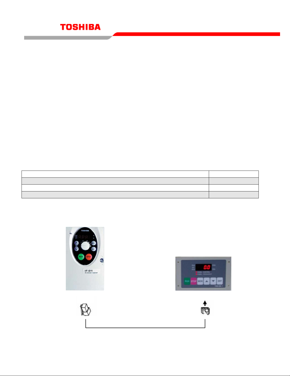
The “Extended Panel (TOS-SN-1)” for TOSVERT series inverter can be used for
programming or monitoring, but does not contain internal memory. Please read the section
regarding safety precaution in the “Extended Panel Operation Manual” before powering up your
inverter. When using the External Panel, the display and adjustment of the inverter can be
controlled remotely for up to 5 meters.
This operation manual gives explanations of how to connect and program the “Extended
Panel.” Please read the entire manual carefully before attempting to control your inverter via the
Extended Panel. In addition, the manual can be used for future operator maintenance and
inspection. The Extended Panel is provided with a connection cable between the inverter and
Option Unit. Any of the cables below may also be used with the TOS-SN-1
Part number of connection cable between the inverter and Option Unit Cable Length
CAB0011
CAB0013
CAB0015
Connections and Start Up
1.5m
3m
5m
CN1
Γ For additional assistance, please contact Toshiba Adjustable Speed Drive Marketing Dept. at (800) 872-2192
Page 2
TOS-SN-1
Connect the Extended Panel to the inverter according to the procedure mentioned below.
1. Wait 10 minutes after the S11 is turned off to insure the drive is denergized. The
charge lamp can be used as a secondary indicator to determine if the drive is still
charged.
2. Connect the communication connectors of the extended panel to the inverter (CN1),
which has the common serial option (communication) connector, with the optional
cable.
3. Insure a secure connection is made between the inverter and the extended panel
once the connection is made.
4. Power on the inverter after connection has been made, and the display should turn
on.
Note: Before removing the cable, insure step 1 is confirmed.
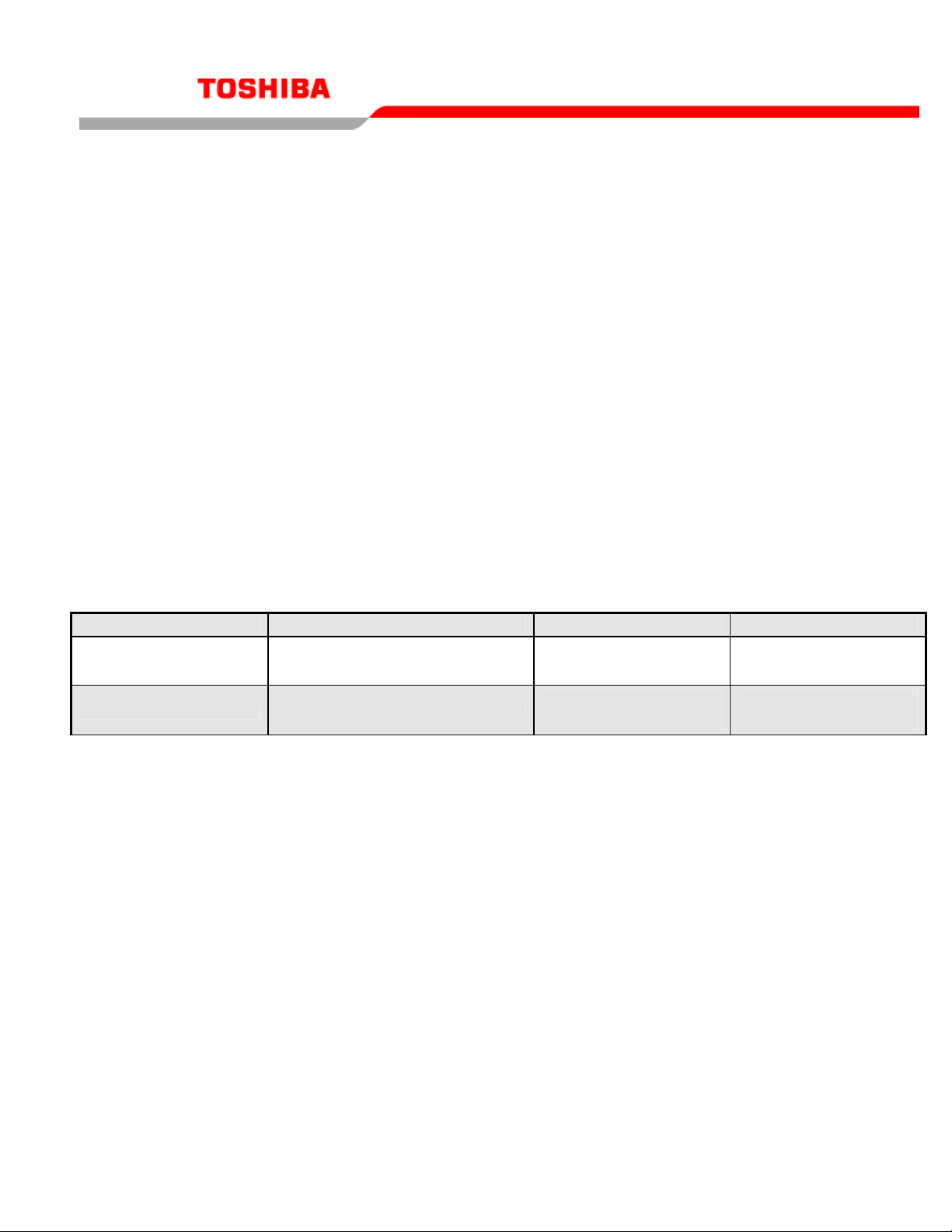
Programming
Parameter Description Default Value New Value
cmod
Command mode selection
Operational Panel
1
Operational Panel
1
fmod
Frequency setting mode selection 1
Built-in Potentiometer
0
Operational Panel
3
Γ For additional assistance, please contact Toshiba Adjustable Speed Drive Marketing Dept. at (800) 872-2192
Page 3
TOS-SN-1
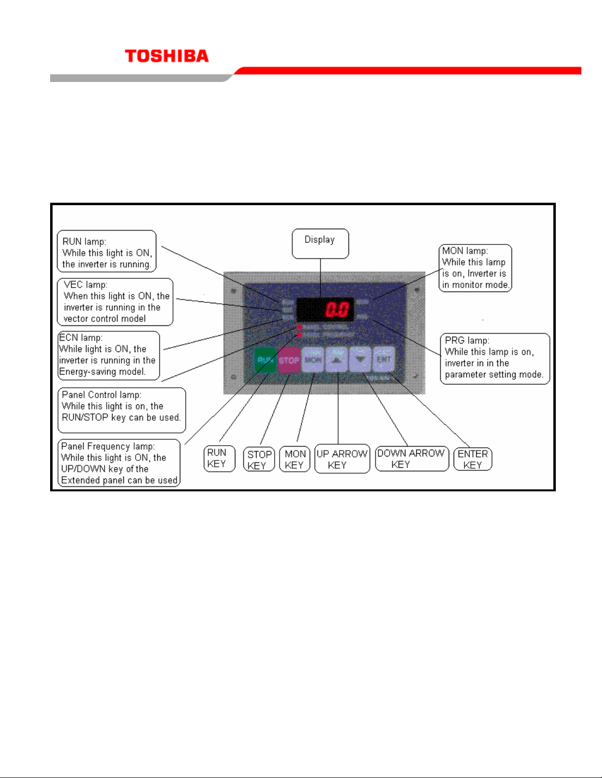
Names and Functions
The names and functions of main parts of the Extended Panel are shown in the following figure.
Even though the Extended panel is connected, the inverter’s panel remains available.
Γ For additional assistance, please contact Toshiba Adjustable Speed Drive Marketing Dept. at (800) 872-2192
Page 4

TOS-SN-1
Mounting
Mount the extended panel (TOS-SN-1) in front of the panel board as mentioned below. Make
an opening for mounting the extended panel in front of the panel board. Refer to “Figure 1.
Panel cut dimensions”, for proper dimensions and then set the extended panel in the opening
with M3 screws, nuts and spacers supplied as accessories. Refer to “Figure2. Mounting of
extended panel” for dimensions of extended panel.
Figure1. Panel cut dimensions (Unit: mm)
Dimensions
Figure2. Dimensions of the extended panel (unit: mm)
Γ For additional assistance, please contact Toshiba Adjustable Speed Drive Marketing Dept. at (800) 872-2192
Page 5

TOS-SN-1
Specifications
Item Specification
Part number TOS-SN-1
Indoors. Altitude of less than 1000m (3280ft) Service
Environment
Must not be exposed to direct sunlight, subject to corrosive
and/or explosive gases, vapor, dust, chips, cutting oil, grinding
agent, etc.
Ambient
Temperature
Storage
Temperature
Relative humidity 20% to 90%
Vibration 5.9m/s2 or less
Cool system Self-cooling
Protection Functions
If you receive an error code while operating the drive from the extended panel, refer to the table
below for solutions to resolve the error.
Error Code Details Causes and Remedies
гAN.E
гON.E
CPU.E
CON.E
RAM error
ROM error
CPU error(watch
dog)
Communication
error
From -100C to+500C (140C to 1040C)
0
From -25
Reset the extended panel. If the same indication
appears again after resetting, ask the dealer to
investigate the cause
The error status will automatically be cancelled by
recovery of normal communication status. Check
connection of the communication cable. After checking
connection of the communication cable, reset the
extended panel. If the same indication appears again
after resetting, ask the dealer to investigate the cause.
C to+650C (-120C to1490C)
(no condensation allowed)
Γ For additional assistance, please contact Toshiba Adjustable Speed Drive Marketing Dept. at (800) 872-2192
Page 6

TOS-SN-1
Safety Precautions
Located on the inverter and in its instruction manual, important information is contained for
preventing injuries to users and damages to assets and for proper use of the device. Read the
instruction manual attached to the inverter along with this manual for complete understanding of
the safety precautions and adhere to the contents of these manuals.
Handling
Danger
Never Disassemble
Prohibited
Mandatory
▼Never disassemble, modify or repair the product.
Disassembling the inverter could cause electric shocks, fire
or
injuries. For repairs, call your agency.
▼Do not remove connectors when the power is on. It could
lead to
electric shocks.
▼Do not put or insert foreign objects such as waste table, bars,
or wires into the product. It could lead to electric shocks or
fire.
▼Do not splash water over the product. It could lead to electric
shocks or fire.
▼Power off the inverter before removing wires.
▼Turn off the power immediately if any abnormalities such as
smokes, smells or abnormal noise are found. Neglecting any
of these conditions could lead to a fire. For repairs, call your
agency.
Transportation and installation
Danger
Prohibited
Mandatory
▼Do not install or operate the inverter if it is damaged or any
part is missing from it. Operating the inverter in a defective
condition could lead to electric shocks or fire. For repairs,
call your agency.
▼ Do not put any inflammable material near the product. It
could ignite a fire if the product sparks because of a
breakdown.
▼ Do not install the product where it could be splashed with
water and the like. It could lead to electric shocks or fire.
▼The product must be used under environmental conditions
prescribed in this operation manual. Using the product under
conditions not specified by the operation manual could lead
to breakdown.
Γ For additional assistance, please contact Toshiba Adjustable Speed Drive Marketing Dept. at (800) 872-2192
Page 7

Prohibited ▼ Do not install the product in any place subject to vibrations or
it could fall. Otherwise it can cause injury to people.
Operation
Prohibited
▼Do not wipe the body with a wet cloth. It could lead to electric
shocks.
▼Do not pull on the cable. It could cause damage or errors.
About disposal of the product
Mandatory
▼Dispose of the product as an industrial waste.
Cautions on use
▼Avoid installation locations that may be subjected to rapid
changes in ambient temperature and/or humidity.
▼ Route the control wires separate from the inverter
input/output power wiring. When disconnecting connection
cable, make sure to hold its connector with care not to give
unreasonable stress to the cable and the unit.
▼ The optional cable connector has locking pawls to prevent
disconnection at the inverter and Option Unit. Disconnect the
connector by pressing the pawl with finger to unlock.
▼ Mount the Option Unit securely on the panel, otherwise it
could fall and cause malfunction or breakdown.
▼ Connect an electromagnetic contactor or something similar
between the inverter and the power source to secure an
external control of emergency to stop operation.
TOS-SN-1
Cautions
Danger
Cautions
Cautions
Γ For additional assistance, please contact Toshiba Adjustable Speed Drive Marketing Dept. at (800) 872-2192
 Loading...