

1
2
CAUTION: TO PREVENT ELECTRICK SHOCK.
DO NOT REMOVE THE ENCLOSURE.
NO U
SER-SERVICIBLE PARTS INSIDE.
Dear Customer,
Thank you for purchasing this Toshiba LCD display.
This manual will help you use the many exciting
features of your new LC D display. Before operating
your LCD display, please read this manual
completely, and keep it nearby for future reference.
WARNING
Important Safety Instructions
1) Read these instructions.
2) Keep these instructions.
3) Heed all warnings.
4) Follow all instructions.
5) Do not use this apparatus near water.
6) Clean only with dry cloth.
7) Do not block any ventilation openings. Install in
accordance with the manufacturer’s instruct ions.
8) Do not install near any heat sources such as
radiators, heat registers, stove s, or other apparatus
(including amplifiers) that prod uce heat.
9) Do not defeat the safety purpose Grounding
of the polarized or grounding
type plug.
A polarized plug has two blades with one wider than
the other. A grounding type plug has two blades and a
third grounding prong. The wide blade or the third
prong are provided for your safety. If the provided plug
does not fit into your outlet, consult an electrician for
replacement of the obsolete outlet.
10) Protect the power cord fr om being walked on or
pinched, particularly at plugs, convenience
receptacles, and the point where they exit from the
apparatus.
11) Only use attachments/accessories specified by
the manufacturer.
12) Refer all servicing to qualified service personnel.
Servicing is required when the apparatus has been
damaged in any way, such as power-supply cord or
plug is damaged, liquid has been spilled or objects
have fallen into the apparatu s, the app aratu s has been
exposed to rain or moisture, does not o perat e normally,
or has been dropped.
Additional Safety Precautions
13) CAUTION: If the LCD display is dropped and the
cabinet or enclosure surface has been damaged or
the LCD display does not operate normally, take the
following precautions:
ALWAYS turn off the LCD display and unplug the
power cord to avoid possible electric shock or fire.
NEVER allow your body to come in contact with
any broken glass or liquid from the damaged LCD
display The LCD panel inside the LCD display
contains glass and a t ox ic liqui d. If th e liqui d com es
in contact with your mouth or eyes, or your skin is
cut by broken glass, rinse the affected area
thoroughly with water and consult your doctor.
ALWAYS contact a service technician to inspect
the LCD display any time it has been damaged or
dropped.
WARNING:
If you decide to wall mount this display, always
use a mounting bracket that has been Listed by
an
independent laboratory (such as UL, CSA, ETL) and
is
appropriate for the size and weight of this display. The use of
inappropriate or non-Listed mounting brackets could result in
serious bodily injury and/or
property damage.
CAUTION:
RISK OF ELECTRIC
SHOCK DO NOT OPEN
Safety Precautions
WARNING: TO REDUCE THE RISK OF FIRE
OR ELECTRIC SHOCK, DO NOT EXPOSE
THIS APPLIANCE TO RA IN OR MOISTURE.
The lightning flash with arrowhead
symbol, within an equilateral triangle, is
intended to alert the user to the
presence of uninsulated “dangerous
voltage” within the product’s enclosure
that may
be of sufficient magnitude to
constitute a risk of electric shock to
persons.
The exclamation point within an
equilateral triangle is intended to alert
the user to the presence of important
operating an
d maintenance (servicing)
instructions
in the literature accompanying
th
e appliance.
3
14) CAUTION:
To reduce the risk of electric shock, do not use
the polarized plug with an extension cord,
receptacle, or other outlet unless the blades can
be inserted completely to prevent blade
exposure.
To prevent electric shock, match wide blade of
plug to wide slot; fully insert.
15) WARNING:
Do not let children swallow the product or play with
the plastic bag. Keep the product an d t he pl ast ic b ag
out of the reach of children.
16) CAUTION:
Do not let water or other liquids come into contact
with the product, as it may result in damage.
17) WARNING:
To prevent the spread of fire, keep candles or
other open flames away from this product at all
times.
Keep the product away from direct sunlight, fire
or a heat source such as a heater. T his may
reduce the product lifetime or result in fire.
Installation, Care, and Service
Installation
Follow these recommen dati on s a nd pr ec auti on s a nd heed
all warnings when installing your LCD display:
18) When operating the LCD display with its AC 220240V power supply in Europe, use the power cord
provided with this display. If a power cord is not supplied with this display, please contact your supplier.
This equipment requires an Earthed mains supply
connection.
19) In the UK, use a BS-approved power cord with
molded plug and black (10A) fuse installed.
20) When operating the LCD display with a 120V, 60Hz
AC power supply in the United States or Canada,
use the power cord provided with the display. If a
power cord is not supplied with the display, please
contact your supplier.
21) For all other cases, use a power cord that matches
the AC voltage of the power outlet and has been
approved by and complies with the safety standards
of your particular country.
22) Avoid displaying fixed patterns for long periods of
time, to avoid image persistence (after image
effects).
23) WARNING: NEVER expose batteries
to excessive heat such as sunshine,
fire or the like.
24) ALWAYS plug the product into an outlet that is
located in such a manner that it can be easily
unplugged in case the product requires service.
25) NEVER route the product’s power cord inside a
wall or similar enclosed area.
26) Never modify this equipment. Changes or
modifications may void: a) the warranty, and b) the
user’s authority to operate this equipment under
the rules of the Federal Communications
Commission.
27) DANGER: RISK OF SERIOUS
PERSONAL INJURY, DEATH, OR
EQUIPMENT DAMAGE!
Never place the LCD display on an
unstable cart, stand, or table. The LCD
display may fall, causing serious
personal injury, death, or serious
damage to the LCD display.
28) When selecting a location for the display,
NEVER allow children to climb on the LCD
display.
29) To avoid damage to this product, never place or
store the LCD display in direct sunlight; hot, humid
areas; or areas subject to excessive dust or
vibration.
30) The product should not be exposed to dripping or
splashing. Objects filled with liquids should not be
placed on the apparatus.
31) Never block or cover the slots or openings in the
LCD display cabinet back, bottom, and sides.
Never place the LCD display:
On a bed, sofa, rug, or similar surface;
Too close to drapes, curtains, or walls; or
In a confined sp ace such as a book case, b uilt-in
cabinet, or any other place with poor v entil ati on.
32) Always leave a space of at least 10cm - 4 (four)
inches around the LCD display. The slots and
openings are provided to protect the LCD display
from overheating and to help maintain reliab le
operation of the LCD display.
33) Never allow anything to rest on or roll over the
power cord, and never place the LCD display
where the power cord is subject to wear or abuse.
34) Never overload wall outlets and extension cords.
Ergonomics
For maximum ergonomic benefit, we recommend the
following:
4
35) For optimum performance, allow 20 minutes for
warm-up.
36) Rest your eyes periodically by focusing on an object
at least 5 feet away. Blink often.
37) Use the preset Size and Position controls with
standard signals.
38) Use the preset Color Setting.
39) Use non-interlaced signals.
40) Do not use primary color blue on a dar k backgr o und,
as it is difficult to see and may produce eye fatigue
due to ins ufficient contrast.
41) Adjust the display’s brightness, contrast, and
sharpness controls to enhance readabilit y.
42) Position the display at a 90° angle to windows and
other light sources to minimize glare and reflections.
Care
For better performance and safer operation of your
TOSHIBA LCD display, follow these recommendations and
precautions:
43) Always unplug the LCD display before cleaning.
Gently wipe the display panel surface (the LCD
display screen) using a dry, soft cloth (cotton, flannel,
etc.). A hard cloth may damage the surface of the
panel. Avoid contact with alcohol, thinner, benzene,
acidic or alkaline solv ent c lea n ers, abrasive cleaners,
or chemical cloths, which may damage the surface.
Never spray volatile compounds such as insecticide
on the cabinet. Such products may damage or
discolor the cabinet.
44) Never hit, press, or place any thing on the back cover.
These actions will damage internal parts.
45) WARNING:
RISK OF ELECTRIC SHOCK
Never spill liquids or pu sh obj ect s of any kind into the
LCD display cabinet slots.
46) During a lightning stor m, do no t touch the connect ing
cables or product.
47) During normal use, the LCD display may make
occasional snapping or popping sounds. This is
normal, especially when the unit is being turned on
or off. If these sounds become frequent or
continuous, unplug the power cord and contac t a
Toshiba Authorized Service Provider.
48) Handle with care w hen t r ans p or ting . S av e p a ck agi ng
for transporting. Please clean the ventilation slots on
the back of the cabinet to remove dirt and dust at
least once a year to maintain reliable operation of
the LCD display.
49) If using the cooling fan continuously, it’s
recommended to clean the ventilation slots at least
once a month.
50) When installing the remote control batteries;
Align the batteries according to the (+) and (-)
indications inside the case.
Align the (-) indication of the batteries first inside
the case.
Service
51) WARNING:
RISK OF ELECTRIC SHOCK
Never attempt to service the LCD display yourself.
Opening and removing the covers may expose you
to dangerous voltage or other hazards. Failure to
follow this WARNING may result in death or serious
injury. Refer all servicing not specified in this manual
to a Toshiba Authorized Service Provider.
52) If you have the LCD display serviced:
Ask the service technician to use only
replacement parts specified by the manufacturer.
Upon completion of service, ask the service
technician to perform routine safety checks to
determine that the LCD display is in safe
operating condition
Important Information
Canadian Department of Communications
Compliance Statement.
CAN ICES-3 (A)/NMB-3(A)
C-UL: Bears the C-UL Mark and is in compliance with
Canadian Safety Regulatio ns accord ing to CAN/CSA C22.2 No.
60950-1.
FCC Declaration of Conformity Compliance
Statement (Part 15):
This device complies with part 15 of the FCC Rules.
Operation is subject to the follo wing two conditions: (1)
This device may not cause harmful interference, and (2)
this device must accept any interference received,
including interference that may cause undesired
operation.
You are cautioned that changes or modifications not
expressly approved by the party responsible for
compliance could void your authority to operate the
equipment.
5
EU Conformity Statement
This product is labeled with the CE Mark in
accordance with the related European
Directives, notably Low Voltage Directive
2006/95/EC, Electromagnetic Compatibility
Directive 2004/108/EC and RoHS Directive
2011/65/EU.
Responsible for CE-Marking is TOSHIBA, 23
Davy Rd, Plymouth, PL6 8BY, UK
Pb Hg, Cd
Please use the supplied power cord to ensure FCC
compliance. If a power cord is not provided, please
contact your supplier.
Warning
This is a Class A product based on the standard of the
VCCI Council. If this equipment is used in a domestic
environment, radio interference may occur, in which case,
the user may be required to take corrective actions.
REACH Information
The Europ ean Union (EU) chemical re gulation, REACH
(Registration, Evaluation, Authorization and Restrictio n of
Chemicals), entered into force on 1 June 2007, with
phased deadlines up to 2018. Toshiba will meet all
REACH requirements and is committed to provide our
customers with information about the presence in our
articles of substances included on the candidate list
according to REACH regulation. Please consult the
following website www.toshiba.eu/reach for about the
presence in our articles of substances included on the
candidate list according to REACH in a concentration
above 0.1% weight by weight.
Disposal of your old product and batteries
The following information is only valid for EU
member states:
Disposal of products
The crossed out wheeled dust bin symbol
indicates that products must be collected and
disposed of separately from household waste.
Integrated batteries and accumulators can be
disposed of with the product. They will be
separated at the recycling centres. The black bar indicates
that the product was placed on the market after August 13,
2005. By participating in separate collection of products
and batteries, you will help to assure the proper disposal of
products and batteries and thus help to prevent potential
negative consequences for the environment and human
health. For more detailed informatio n ab out the collection
and recycling programmes available in your country,
please contact your local city office or the dealer where
you purchase d the product.
Disposal of batteries and/or accumulator s
The crossed out wheeled dust bin symbol
indicates that batteries and/or accumulators
must be collected and disposed of separately
from household waste. If the battery or
accumulator contains more than the
specified values of lead (Pb), mercury
(Hg), and/or cadmium (Cd) defined in the Battery
Directive (2006/66/EC), then the chemical symbols for
lead (Pb), mercury (Hg) and/or cadmium (Cd) will
appear below the crossed out wheeled dust bin symbol.
By participating in separate collection of batteries, you
will help to assure the proper disposal of products and
batteries and thus help to prevent pote ntial negative
consequences for the environment and human health. For
more detailed information about the collection and
recycling programmes available in your country, please
contact your local city office or the shop where you
purchased the product.
Important notes about your display
The following symptoms are technical limitations of
LCD display technology and are not an indication of
malfunction; therefore, Toshiba is not responsible for
perceived issues resulting from these symptoms.
(1) About afterimage Prevention
When the same contents have been displayed for
a long period of time, the previous contents may
remain on the screen even when you have
changed the contents.
This phenomenon is called an afterimage.
Although the afterimage disappears eventually as
the displayed contents change, if the same
contents stay displayed for a long period of time,
they may re main on the screen perma nently.
Please be careful not to display the same contents
for too long.
(2) About the display
The LCD panel is made with high precision
technology, and it displays a collection of line
pixels.
There are 99.99% or more effective pixels. There
are pixels which do not generate light (0.01% or
less), and there are also pixels which generat e
light constantly. Please be reminded that this is
not a malfunction.
Note:
Interactive video games that involve shooting a “gun”
type of joystick at an onscreen target may not work with this
display.
WARNING: This product contains chemicals, including
lead, known to the State of California to cause cancer
and birth defects or other reproductive harm.
Wash hands after handling.

6
Trademark Information
Windows is either a registered trademark or trademark
of Microsoft Corporation in the United States and/or
other countries.
The terms HDMI and HDMI High-Definition
Multimedia Interface, and the HDMI Logo are
trademarks or registered trademarks of HDMI
Licensing L LC in the United States and other
countries.
All other brand and product names are trademarks or
registered trademarks of their respective companies.
Copyright
Under the copyright laws, this guide cannot be reproduced
in any form without the prior written pe rmission of
Toshiba. No patent liability is assumed, however, with
respect to the use of the information contained herein.
© 2015 by Toshiba Lifestyle Products & Services
Corporation. All rights reserved.
Notice
The information contained in this manual, including but
not limited to any product specifications, is subject to
change without no t ice .
TOSHIBA LIFESTYLE PRODUCTS & SERVICES
CORPORATION (TOSHIBA) PROVIDES NO
WARRANTY WITH REGARD TO THIS MANUAL
OR ANY OTHER INFORMATION CONTAINED
HEREIN AND HEREBY EXPRESSLY DISCLAIMS
ANY IMPLIED WARRANTIES OF
MERCHANTABILITY OR FITNESS FOR ANY
PARTICULAR PURPOSE WITH REGARD TO ANY
OF THE FOREGOING.
TOSHIBA ASSUMES NO LIABILITY FOR ANY
DAMAGES INCURRED DIRECTLY OR
INDIRECTLY FROM ANY TECHNICAL OR
TYPOGRAPHICAL ERRORS OR OMISSIONS
CONTAINED HEREIN OR FOR DISCREPANCIES
BETWEEN THE PRODUCT AND THE MANUAL. IN
NO EVENT SHALL TOSHIBA BE LIABLE FOR
ANY INCIDENTAL, CONSEQUENTIAL, SPECIAL,
OR EXEMPLARY DAMAGES, WHETHER BASED
ON TORT, CONTRACT OR OTHERWISE, ARISING
OUT OF OR IN CONNECTION WITH THIS
MANUAL OR ANY OTHER INFORMATION
CONTAINED HEREIN OR THE USETHEREOF.

7
Contents
PRODUCT FEATURES ................................................................................................................................................... 9
PACKAGE CONTENTS ................................................................................................................................................... 9
UNPACKING ....................................................................................................................................................................... 9
PACKING LIST ................................................................................................................................................................... 10
INCLUDED ACCESSORIES ..................................................................................................................................................... 11
PRODUCT OVERVIEW ................................................................................................................................................ 12
MAIN POWER SWITCH AND AC INLET ................................................................................................................................... 12
POWER SWITCHES ............................................................................................................................................................. 12
INPUT AND OUTPUT CONNECTORS ....................................................................................................................................... 13
OPERATING THE DISPLAY .......................................................................................................................................... 15
SETTING UP THE DIS PL AY .................................................................................................................................................... 15
TURNING THE DISP LAY ON AND OFF ..................................................................................................................................... 16
ADJUSTING THE VOLUME AND INPUT SOURCE ........................................................................................................................ 16
USING THE KEYPAD ........................................................................................................................................................... 17
READING THE STAT US LED .................................................................................................................................................. 17
AVOIDING IMAGE RETENTION .............................................................................................................................................. 18
ROTATING THE DIS PLAY ...................................................................................................................................................... 19
USING THE REMOTE CONTROL ............................................................................................................................................. 20
LOCKING THE OSD (ON-SCREEN DIS PL AY) ............................................................................................................................. 20
CHANGING THE REMOTE CONTROL BATTER Y .......................................................................................................................... 21
USING THE MENUS ................................................................................................................................................... 22
NAVIGATING THROUGH THE MENU SYSTEM............................................................................................................................ 22
INPUT MENU ................................................................................................................................................................... 23
PICTURE MENU ................................................................................................................................................................ 24
PICTURE MENU (CONTINUED) - RGB ADJUSTMENT ................................................................................................................. 25
AUDIO MENU .................................................................................................................................................................. 26
OSD SETTINGS MENU ....................................................................................................................................................... 27
SETUP MENU ................................................................................................................................................................... 28
SETUP MENU (CONTINUED) - REAL TIME CLOCK ..................................................................................................................... 29
ADVANCED SETUP MENU ................................................................................................................................................... 30
ADVANCED SETUP MENU (CONTINUED) - WAKE UP FROM SLEEP ............................................................................................... 31
COMMUNICATION MENU ................................................................................................................................................... 32
INFORMATION MENU ........................................................................................................................................................ 33
CONTROLLING THE DISPLAY USING RS-232 ............................................................................................................................ 33
Connection .............................................................................................................................................................. 33
RS-232C Communication Specifications .................................................................................................................. 33
Communication Command Format ......................................................................................................................... 34
Monitor Settings ...................................................................................................................................................... 34
CONNECTING THE TOUCH SCREEN (TD-U852TS ONLY) .............................................................................................. 35
TOUCH USB CABLE CONNECTION ........................................................................................................................................ 35
SYSTEM REQUIREMENTS ..................................................................................................................................................... 36
SOFTWARE INSTA LL ATION ................................................................................................................................................... 36
TOUCH SCREEN CONFIGURATION ......................................................................................................................................... 37
TROUBLESHOOTING ................................................................................................................................................. 38
SUPPORTED TIMINGS ............................................................................................................................................... 39
SERIAL COMMAND LIST ............................................................................................................................................ 40
IR CONTROL CODE LIST ..............................................................................................................................................47
SPECIFICATIONS ........................................................................................................................................................ 48
DIMENSIONS (TD-U852) ........................................................................................................................................... 49

8
DIMENSIONS (TD-U852TS) ........................................................................................................................................ 50
COMPLIANCE ............................................................................................................................................................ 51
APPENDIX I: MOVING AND CARRYING NOTICE ......................................................................................................... 52
APPENDIX II: INSTALLING A WALL MOUNT ............................................................................................................... 53
APPENDIX III: INSTALLING AN OPS MODULE ............................................................................................................. 54
APPENDIX IV: PIP MODE & PIP MATRIX .................................................................................................................... 55
APPENDIX V: RECOMMENDED IR EXTENDER POSITIONS ............................................................................................57
APPENDIX VI: CONTROLLING THE DISPLAY THROUGH ETHERNET PORT .................................................................... 58
CONNECTION ................................................................................................................................................................... 58
SETTING IP ADDRESSES ...................................................................................................................................................... 59
Set the IP Addresses of the PC and Monitor ............................................................................................................ 59
Checking the Connection ......................................................................................................................................... 59
CONTROLLING THE MONITOR FROM A PC VIA LAN ................................................................................................................. 60
Monitor Settings ...................................................................................................................................................... 60
CONFIGURING SETTINGS USING PC BROWSE R SOF TWARE ........................................................................................................ 61
Logging into the Monitor from the Browser............................................................................................................ 61

9
Product Features
The TD-U852 series is a ultra-high definition display that supports a full 3840x2160 @ 60 Hz resolution
and can display 1.073 billion col or s .
It supports a full range of interface types, including DisplayPort, HDMI™, VGA, Audio in, A udio out, IR
extender, RS232 and Ethernet.
Features
o Up to 3840x2160 @ 60 Hz resolution
o High-resolution, high-speed IR touch sensing for up to 6 simultaneous touches (TD-U852TS only)
o Can display up to 4 video sources simultaneously
o (2) DisplayPort inputs (1 for TD-U852TS)
o (4) HDMI inputs
o VGA input
o OPS slot (TD-U852TS only)
o Analog audio input
o Analog audio output
o IR extender input with IR extender (included)
o Full-range internal speakers
o Signal source auto detection
o Selectable OSD keypad lock
o Landscape & Portrait support
o Flexible ON/OFF scheduler
o Low power consumption
o RS232c and Ethernet control
Package Contents
Unpacking
o The TD-U852 series display is packed using cushions to protect the display during shipping.
o Before unpacking your display, prepare a stable, level, and clean surface near a wall outlet.
o Set the display b ox in an upright position and open fr om the top of the box before removing the to p
cushions.
• Step 1: Remove the white handle and cut the banding
• Step 2: Remove the top cushion and take the accessory bag out.
10
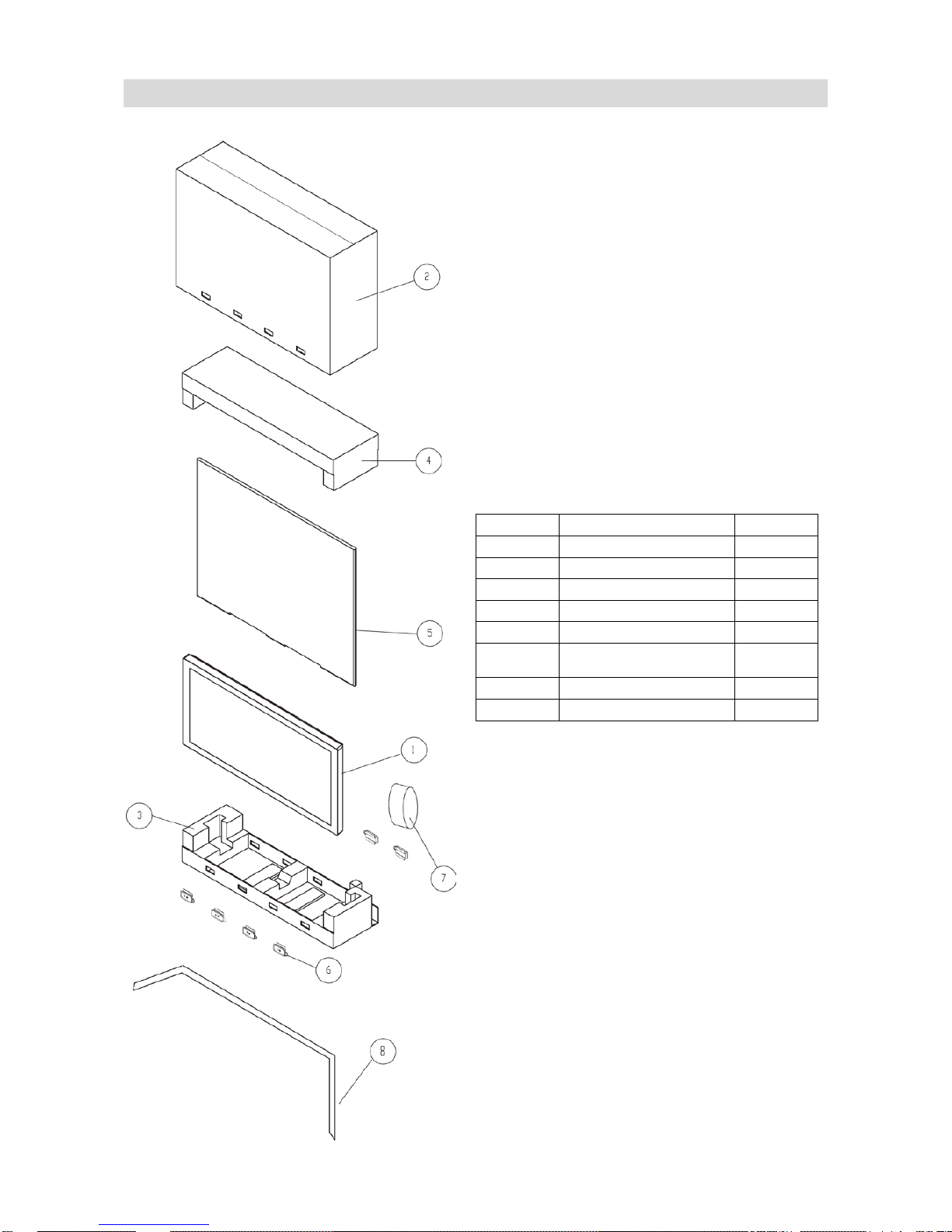
Packing List
Item No.
Description
Quantity
1
Display
1 2 Carton
1 3 Cushion Bottom
1 4 Cushion Top
1 5 Poly Bag
1
6
Carton Lock
(White Handle)
8
7
Accessory Bag
1
8
Packing Band
3
11
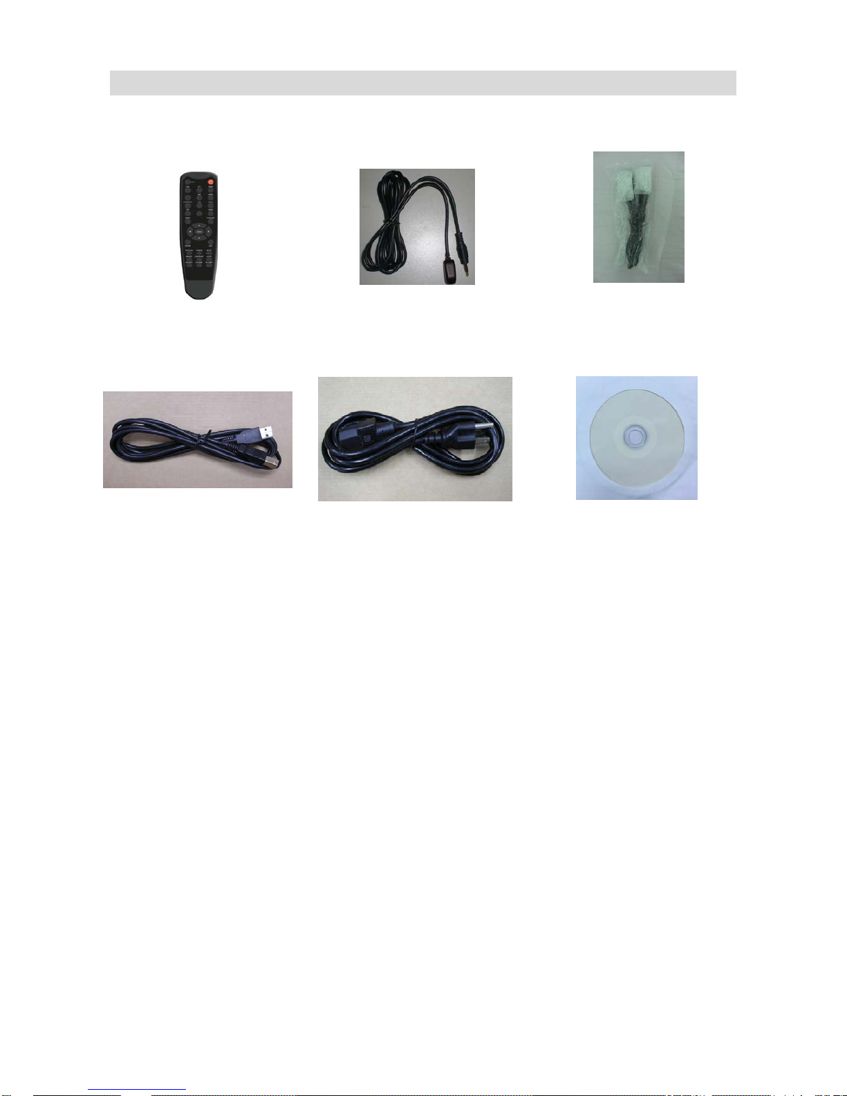
Included Accessories
IR Remote Control
(Battery included)
IR Extender
HDMI Cable (6 ft)
USB Type B to A Cable
(6 ft, TD-U852TS only)
Power Cord – black
(6 ft)
CD-ROM
Disk Content:
User Manual
Touch Driver
12
Product Overvi ew
When operating the TD-U852 series display, ambient room conditions should not exceed the following:
o Operating temperature: 5˚C to 40˚C (41˚F to 104˚F)
o Humidity : 35% ~ 85% RH (non-condensing)
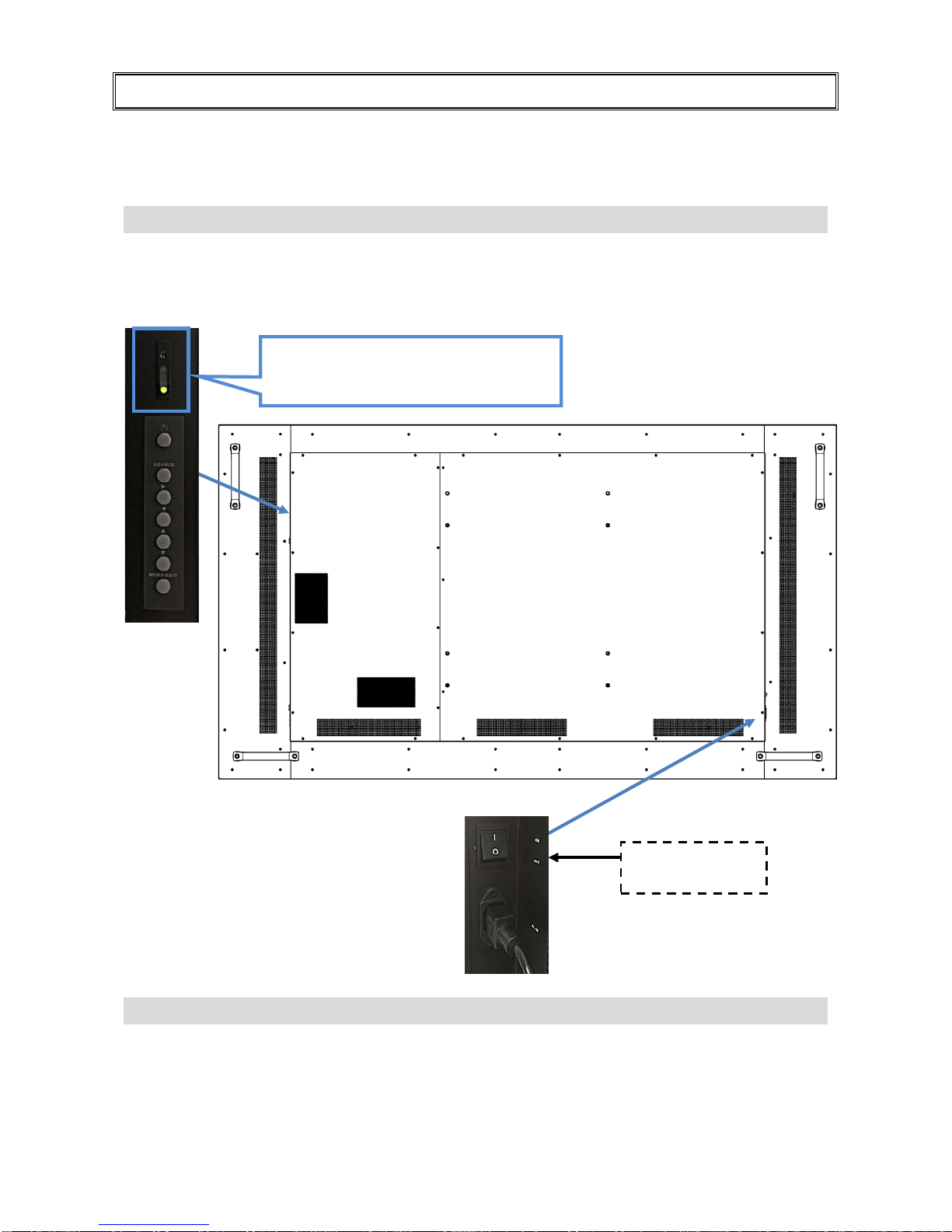
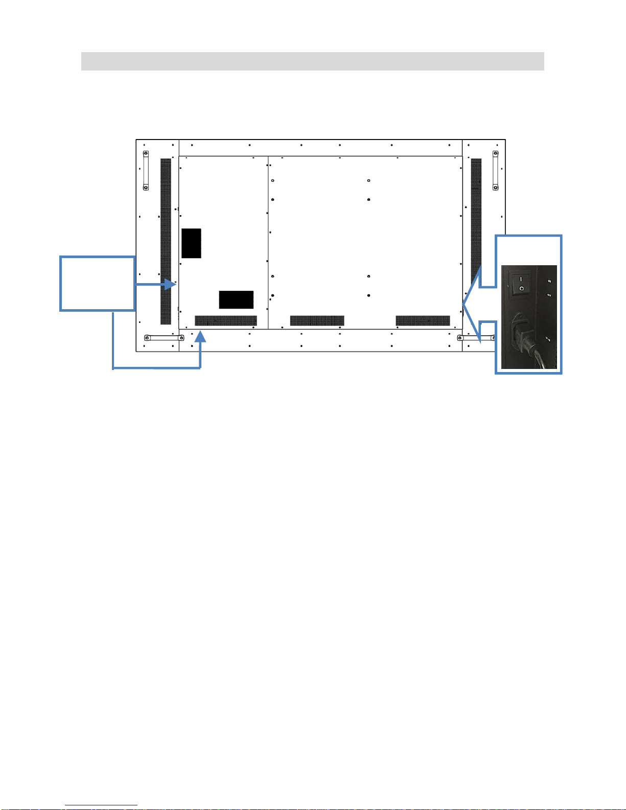
Main Power Switch and AC Inlet
The power cord is used to connect the display to an AC wall outlet. Plug the power cord into the AC inlet
on the side of the display.
The main power switch is located directly above the AC inlet; press “ | ” to turn power on, and “O” to turn
power off.
Power Switches
o The on/off switch is the top button on the display keypad.
o The on/off switch is also located on the remote control.
OSD
Keypad
Main power –
Switch
AC
Inlet
“I“ is power on
“O” is power off
Status LED / Light Sensor / IR Receiver
(See page 17 for more information about
LED illumination.)
13
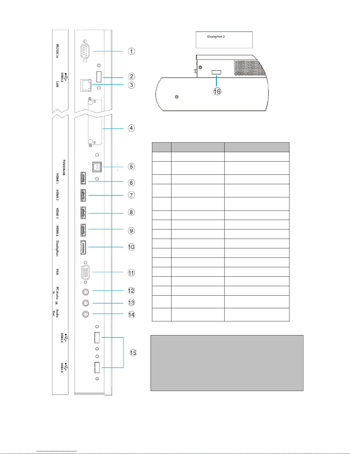
Input and Output Connectors
Power
Input and
Output
Connectors
14
No.
Name
Connector
1 RS232 D-Sub 9 pin
2
USB 3.0
(TD-U852TS only)
USB Type A
3 LAN RJ-45
4
OPS Slot
(TD-U852TS only)
OPS Module
5
Touch USB
(TD-U852TS only)
USB Type B
6 HDMI 1 HDMI Input
7 HDMI 2 HDMI Input
8 HDMI 3 HDMI Input
9 HDMI 4 HDMI Input
10 DisplayPort 1 DisplayPort Input
11 VGA D-Sub 15 pin
12 PC Audio In Mini Jack
13 IR Extender Mini Jack
14 Audio Out Mini Jack
15
USB 2.0
(TD-U852TS only)
USB Type A
16
DisplayPort 2
(TD-U852 only)
DisplayPort Input
Note:
1. The drawings are only given as a better
understanding of cable connections. The I/O sockets
vary upon different models.
2. USB 2.0 & 3.0 ports can only be used when an OPS
module is connected.
3. See Appendix III for more information about how to
install an OPS module.
15
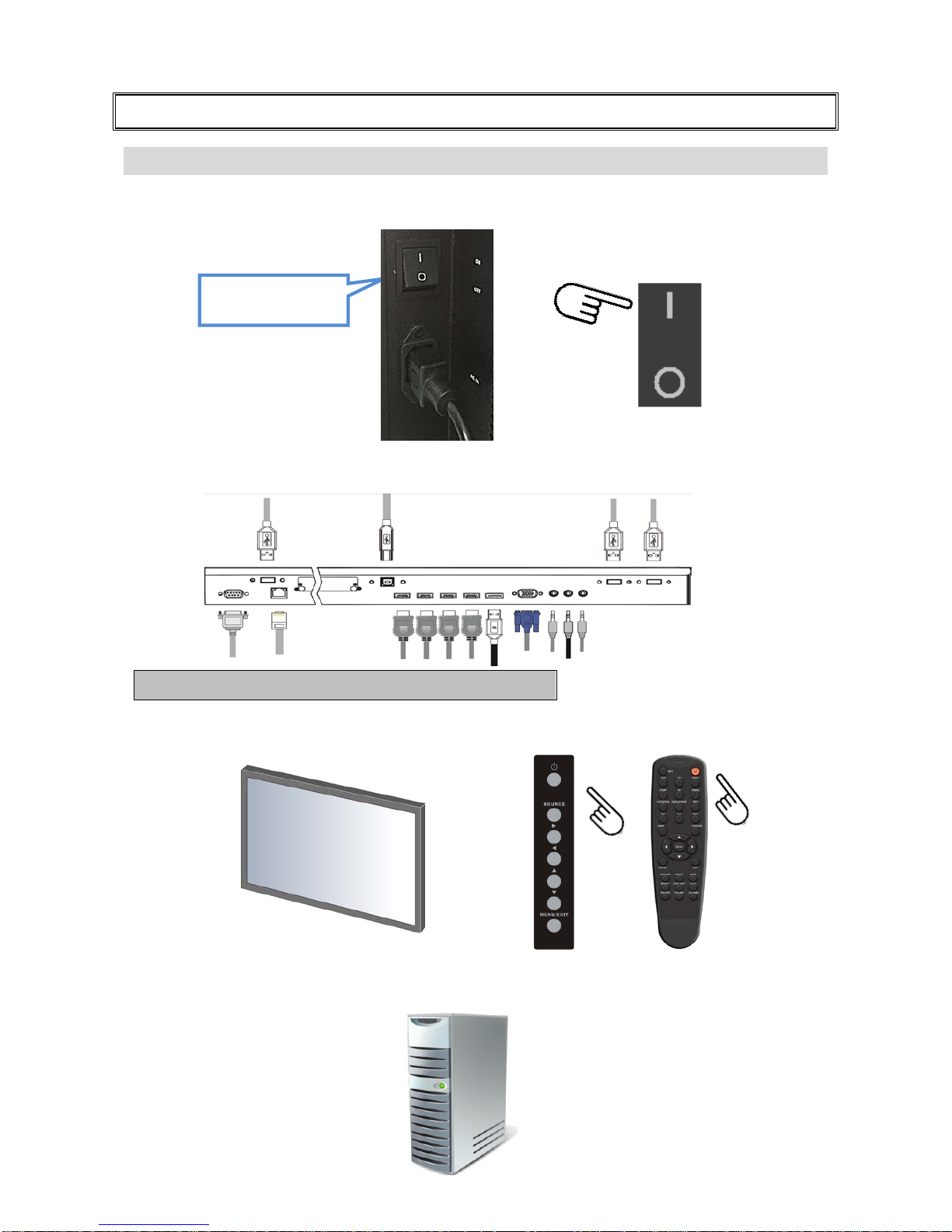
Operating the Display
Setting up the Display
Step 1: Plug in the power cable and turn on the AC power switch (without turning on the signal source
device(s)).
Step 2: Plug in the signal source cables.
Step 3: Press the power key on the display’s keypad or the power key on the remote control to turn on
the display.
Step 4: Turn on the pow er of the signal source device(s) t o begin sending a signal to the display.
Note: The I/O sockets vary upon different models.
“I“ is power on
“O” is power off

16
Turning the Display On and Off
Turning the display on
1. Connect the display to an AC wall outlet
2. Ensure the AC switch is set to “ | “.
3. Press the power button on the remote control or keypad.
Turning the display off
With the power on, press the power button on the remote control or keypad to put the display into
standby mode. To turn off power completely, turn the AC switch to “O” or disconnect the AC power cord
from the power outlet.
Note: If there is no signal input for a period of time, the display will automatically go into power
saving (sleep) mode.
Adjusting the Volume and Input Source
Adjusting the Volume
1. Using the remote, press the VOLUME- or VOLUME+ to increase or decrease the volume.
2. Press the MUTE button to temporarily turn off all sound. To restore the sound, press the MUTE button
again.
Selecting the input source
1. Using the remote, press the desired source button
(DP1, DP2, HDMI1, HDMI2, HDMI3, HDMI4,
VGA, OPS)
2. Or press SOURCE on the display keypad, use the arrow buttons (
) to navigate to th e desired
input source, and press ENTER:
DisplayPort1
DisplayPort2 (TD-U852 only)
HDMI1
HDMI2
HDMI3
HDMI4
VGA
OPS (TD-U852TS only)
3. If the display cannot find a source, a “No signal” message will appear.
17
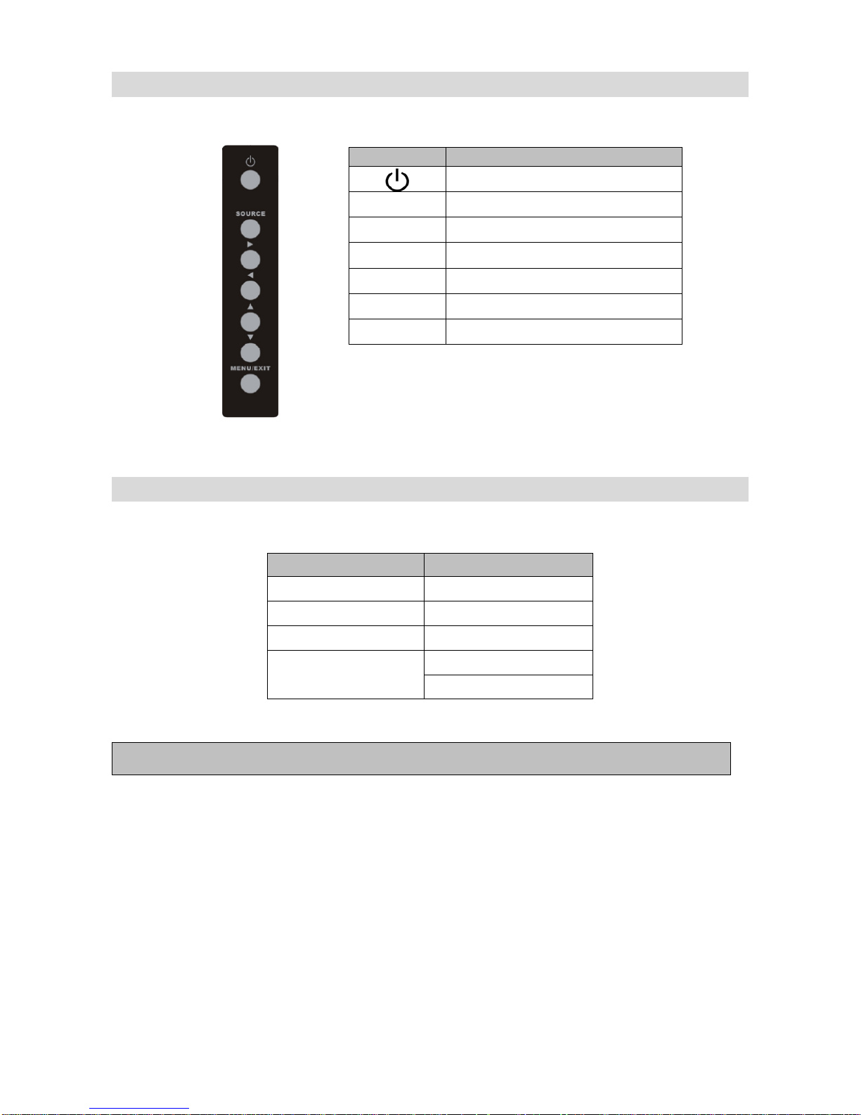
Using the Keypad
Reading the Status LED
Note: If the Status LED is set to “Off” in the OSD menu, the status LED will not operate.
Key
Descriptions
Power on/Power off
Source Source selection
Menu Right
Menu Left
Menu Up
Menu Down
Menu/Exit Menu/Exit selection
LED Illumination
Condition
Green
Normal operation
Blinking Orange
No signal
Orange
Power Saving
Off
Power off
AC off
18
Avoiding Image Retention
Fixed images displayed over a long periods of time may cause image “burn-in” or image retention.
Image retention is not covered under warranty.
Follow the recommendations below to avoid image retention.
Operate display within its rated ambient environment
o Operating temperature: 5°C to 40°C (41°F to 104°F)
o Humidity: 35% ~ 85% RH (non-condensing)
Avoid static content
o During each 24 hour period, turn the display off for a continuous 6 hours.
o Display dynamic (moving) images whenever possible.
o Avoid displaying static (fixed) images for long periods of time.
o Consider using a screen saver of signal source to avoid displaying static (fixed) video content
continuously.
Set IRFM to ON
To help avoid image retention, it is recommended that t he I RFM featur e be set to “ON”. This feature can
be selected via the OSD (on screen display) under “Adv anced Settings”/ “IRFM”/ “ON”.
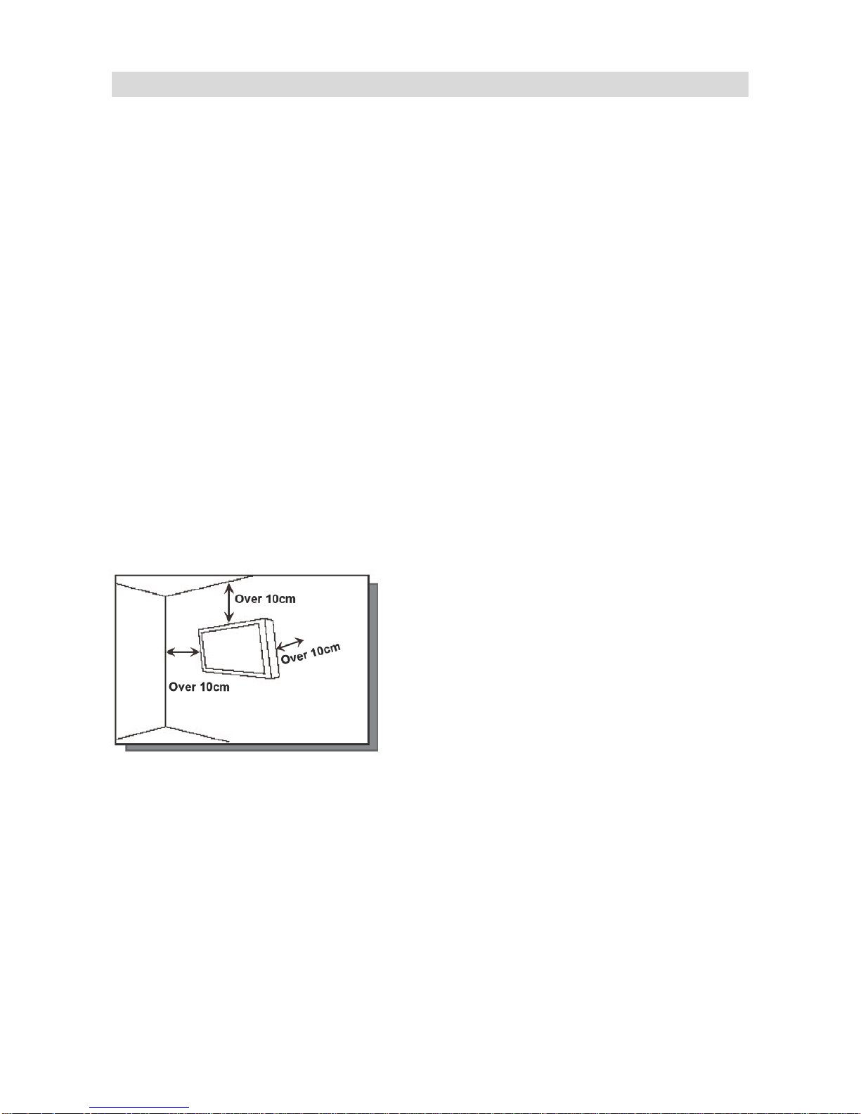
Air Ventilation
Please do not install the display directly under the sunshine or humidity / high temperature places for
fear that the quality is effected. Installing the display over 10 cm from each wall side is the suggested
installing position.
19
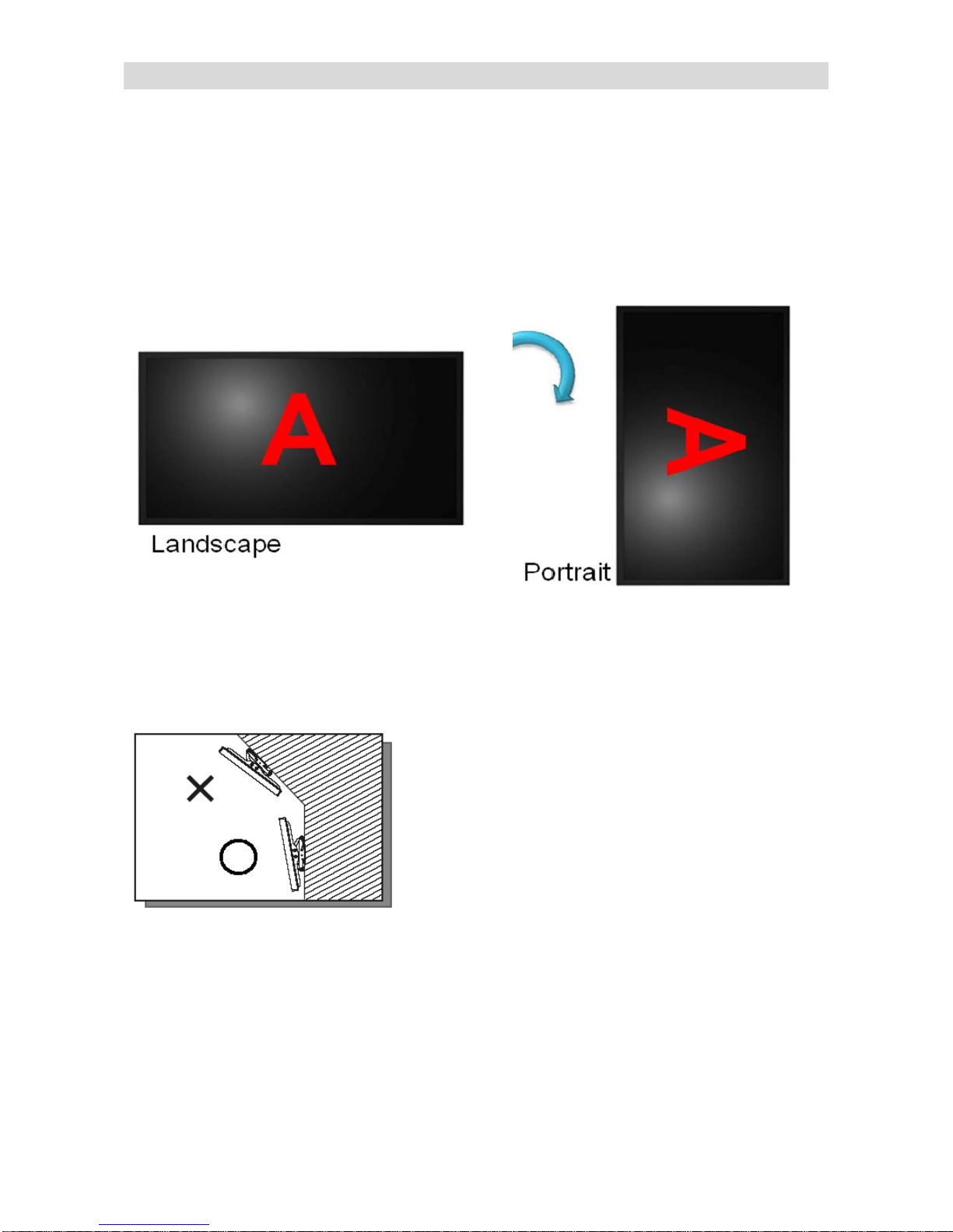
Rotating the Display
When using the display in portrait position, the display should be rotated cloc kwise so t hat the le ft side i s
moved to the top. (Do NOT rotate the display counter-clockwise or upside down) This will allow for
proper ventilation for the display. Improper ventilation may shorte n t he li fetime of the display. After rotate
the display, change the OSD rotation setting from “Landscape” to “Portrait” in the OSD menu.
Tilt Setting
Tilt angle limitation is within ±10 degrees.

20
Using the Remote Control
Locking the OSD (On-screen Display)
To lock the remote control (to prevent tampering display settings):
Press Enter, Enter, Exit, Exit, Enter and Exit on the remote control.
To unlock the remote control:
Press Enter, Enter, Exit, Exit, Enter and Exit on the remote control by sequence again and all k e ys will be
unlocked.
No
Function
Description
1.
Turns the display on and off
2.
INFO
Provides source and resolution information
3.
VGA
Selects the VGA source
DP1
Selects the DisplayPort 1 source
HDMI1
Selects the HDMI 1 source
4.
Blank
---
DP2
Selects the DisplayPort 2 source (TD-U852 only)
HDMI2
Selects the HDMI 2 source
5.
P-POSITION
Picture-in-Pictur e Pos itio n
OPS
Turns on OPS (open pluggable specification)
feature (TD-U852TS only)
HDMI3
Selects the HDMI 3 source
6.
PIP
Turns the Picture-in-Picture feature on and off
Blank
---
HDMI4
Selects the HDMI 4 source
7. SWAP
Swaps the main source and Picture-in-Picture
Source
8.
P-SOURCE
Selects the Picture-in-Picture Source
9.
MENU
Opens the display’s on-screen menu system. When
the menu system is already open, pressing this
button will select the previous submenu
,, ,
Navigates through submenus and settings
10.
EXIT
Closes the menu system
11.
ENTER
Selects highlighted menu choices
12.
SCALING
T oggles between different aspect ratios: Full Screen,
Letter Box, 4:3 (Pillar B ox ) and 1:1 (Native)
FREEZE
Freezes the current source image
MUTE
Turns off the sound
BRIGHT
Adjusts the brightness
CONTRAST
Adjusts the contrast
AUTO
Auto adjustment VGA source
SOURCE
Allows selection of the different sources
VOLUME-
Decreases the sound volume
VOLUME+
Increases the sound volume

21
Changing the Remote Control Battery
1.
Remove the battery cover
Slide back and remove the battery cover in the
direction of the arrow.
2.
Insert the batteries
Align and insert two AAA batteries according to
their plus and minus ports (as indicated in the
remote control).
3.
Close the battery cover
Replace the battery cover in the direction of
the arrow and snap it back into place.
i. The drawings above are only given as a better understanding of actual operations.
ii. Used batteries needed to follow the city rule to be discarded.
iii. Avoid keeping used, old batteries inside the remote control, causing leakage of internal liq uid
resulting metal rust or fatal damage to the remote control hand unit.
iv. Battery to be used according to the instruction.
About the remote control
Don’t drop, shake or bump.
Don’t place on wet materials.
Don't dismantle.
Don’t place in locations with exposure to high-temperature or high-hu midity levels.

22
Using the Menus
Navigating through the Menu System
1. With the power on, press MENU. The Im age Settings menu will display.
2. Within the menu, use ,,, , and ENTER to navigate through the menus and adjust options.
3. Press MENU to return to the previous menu. To exit the menu system, press EXIT.

23
Input Menu
This menu is used for selecting the main input source (Main) and up to three Picture-in-Picture input sources
(Sub1, Sub2 and Sub3). Up to four sources can be displayed at the same time.
Main Input
Select the main input source.
Options: DisplayPort1, Dis playPort2 (TD-U852 only), HDMI1, HDMI2, HDMI3,
HDMI4, VGA, OPS (TD-U852TS only)
Auto Scan
Select whether the display will automatically scan for an input source (main or
sub).
Options: Off, Main, PxP, All; Default: Off
Note:
1. PxP stands for the combination of all PiP modes.
2. Auto-scanning the main input source is disabled when PxP is selected.
PiP Mode
Select the PiP (Picture-in-Picture) mode.
Options: Off, PiP, PbP, 3Window, 4Window; Default: Off
Note: See Appendix IV for more details about display sizes and PiP positions.
Sub1 Input
Select the source for the primary PiP window.
Options: DisplayPort1, Dis playPort2 (TD-U852 only), HDMI1, HDMI2, HDMI3,
HDMI4, VGA, OPS (TD-U852TS only)
Note: This function is only available when PiP Mode is set to PiP, PbP, 3Window or
4Window.
Sub2 Input
Select the source for the secondary PiP window.
Options: DisplayPort1, Dis playPort2 (TD-U852 only), HDMI1, HDMI2, HDMI3,
HDMI4, VGA, OPS (TD-U852TS only)
Note: This function is only available when PiP Mode is set to 3Window or 4Window.
Sub3 Input
Select the source for the tertiary PiP window.
Options: DisplayPort1, Dis playPort2 (TD-U852 only), HDMI1, HDMI2, HDMI3,
HDMI4, VGA, OPS (TD-U852TS only)
Note: This function is only available when PiP Mode is set to 4Window.
PIP Size
Select the size of the primary PiP window.
Options: Small, Mid, Large
Note: This function is only available when PiP Mode is set to PiP.
PIP Position
Set the position of the primary PiP window.
Options: TopR, TopL, BotR, BotL
Note: This function is only available when PiP Mode is set to PiP.

24
Swap
Swap the main input source with the primary PiP source.
Note: This function is only available when PiP Mode is set to PiP, PbP, 3Window or
4Window.
Clone Color Settings
Copy the color settings of main input to sub1-3 inputs.
Options: Yes, No
Picture Menu
This menu is used for making common image adjustments.
Picture Format
Adjust the picture format of the screen.
Options: Full Screen, Letterbox, 4:3 (Pillar box), 1:1 (Native)
Default: Full Screen
Scheme
Press or to select one of the following:
Options: Personal, High Bright, Cinema, Game, Standard
Default: High Bright
Contrast
Increase or decreas e the contrast of p icture. Press or , select th e desired
level, and then press ENTER.
Range: 0~100; Default: 60
Brightness
Increase or decrease the brightnes s of picture. Press or, s elect the desired
level, and then press ENTER.
Range: 0~100; Default: 30
Sharpness
Adjust the definition of picture. Press or , select the desired level, and then
press ENTER.
Range: 0~100; Default: 80
Hue
Increase or decrease the hue of colors. Press or, select the desired level,
and then press ENTER.
Range: 0~100; Default: 50
Note: To obtain a better video image quality, adjust the hue of colors little by little.
Saturation
Adjust th e brilliance and brightness. Pr ess or, select the desired level, and
then press ENTER.
Range: 0~100; Default: 65
Backlight

25
Increase or decrease the intensity of the L CD backlight. Press or, select the
desired level, and then press ENTER.
Range: 0~100; Default: 100
Color Temp & Gamma
Select gamma curve.
Options: Off, 1.85~2.6; Default: 2.2
Select a color temperature or select User to make RGB adjustments.
Options: User, 5000K, 6500K, 7500K, 9300K and 13000K; Default: 13000K
HDMI RGB Range
Select one of the options below t o adjust RGB range for the HDMI input in the
next following menu.
Options: Auto, Full, Limited; Default: Auto
Picture Menu (continued) - RGB Adjustm ent
Red Gain
Adjust the red color in bright area.
Range: 0~100
Default: 100
Green Gain
Adjust the green color in bright area.
Range: 0~100
Default: 100
Blue Gain
Adjust the blue color in bright area.
Range: 0~100
Default: 100
Red Offset
Adjust the red color in dark area.
Range: 0~100
Default: 50
Green Offset
Adjust the green color in dark area.
Range: 0~100
Default: 50
Blue Offset
Adjust the blue color in dark area.
Range: 0~100
Default: 50
Note: The color temperature must be set to "User" prior to making RGB adjustments.

26
Audio Menu
This menu is used for adjusting volume settings.
Volume
Adjust the sound. Press or , select the desired level, and then press ENTER.
Range: 0~100
Default: 50
Treble
Adjust the sound in high tones (treble). Press or , select the desired level,
and then press ENTER.
Range: -6~6
Default: 0
Bass
Adjust the sound in low tones (bass). Press or , select the desired level, and
then press ENTER.
Range: -6~6
Default: 0
Balance
Adjust the balance of the left and right speakers. Press or , select the
desired level, and then press ENTER.
Range: -6~6
Default: 0
Internal Speaker
Turn the internal speaker on or off.
Default: On
Audio Source
Select the audio source.
Options: Line-In, DisplayPort 1, DisplayPort 2 (TD-U852 only), HDMI1, HDMI2,
HDMI3, HDMI4, OPS (TD-U852TS only)
Default: Sound of the main input
Note: The input which is active on the OSD can be selectable.

27
OSD Settings Menu
This menu is used to make initial set-up adjustments to the OSD (On-Screen Display) menu and other
on-screen messages.
Horizontal
Adjust the horizontal position of the OSD menu. Press or , select the desired
level, and then press ENTER.
Range: 0~100
Default: 50
Vertical
Adjust the vertical pos ition of the OSD m enu. Press or , select th e desired
level, and then press ENTER.
Range: 0~100
Default: 50
Transparency
Adjust the transparenc y of the OSD menu. Press or to select the desired
level, and then press ENTER.
Range: 1~4, Off
Default: Off
OSD Timeout
Adjust the time in s econds before the OSD menu disappears. Press or to
select the desired level, and then press ENTER.
Options: 5~60 sec
Default: 30 sec
OSD Rotation
Select the OSD Rotation. Press select the rotation.
Options: Landscape, Portrait
Default: Landscape
Language
Select the OSD language.
Options: English, Japanese, German
, Spanish, French, Italian, Polish,
Portuguese, Swedish, Turkish
Default: English
Splash Screen
Launch a logo when the display is turned on.
Default: On
Information Display
Messages of Input and Signal Status, Mute, Freeze, and So urce are available
when this option is turned on, but hidden when it is turned off.
Default: On

28
Setup Menu
Auto Adjustment
Force the display to reacquire and lock to the input signa l (VGA source only).
This is useful when the s ignal quality
is marginal. Note: T his feature does not
continually reacquire the signal.
Options: No, Yes; Default: No
H. Position
Adjust the horizonta l position of the image (VGA sou rce only). Press or ,
select the desired level, and then press ENTER.
Range: 0~100; Default: 50
V. Position
Adjust the vertical position of the image (VGA source only). Press or , select
the desired level, and then press ENTER.
Range: 0~100; Default: 50
Phase
Adjust the phase of the displayed signal (VGA source only). Press or , select
the desired level, and then press ENTER.
Range: 0~100
Clock
Adjust the clock of the displa yed signal ( VGA s ource onl y). Press or , select
the desired level, and then press ENTER.
Range: 0~100
Zoom
Adjust the zoom (oversc an) of the image. Press or , select the desired le vel ,
and then press ENTER.
Range: 0~100
Power LED
Enable or disable the status LED.
Options: On, Off; Default: On
OPS Power Down Check (TD-U852TS only)
By enabling OPS power-down check, the system will inspect the power status of
OPS module after the power button is pressed to power off the display. If its
power status remains ON, the system will command the OPS module to power
OFF before the display enters the power down mode.
Default: On
Real Time Clock
Set the internal clock of the display, and to power on and off the display at preset
times if desired.
Options: User mode, Workday mode, Everyday mode; Default: User mode
Select one of the options above to configure the internal clock settings of
selected mode in the next following menu.

29
Setup Menu (continued) - Real Time Clock
This menu is used to set the internal clock of the display, and to power on and power off the display at preset
times if desired.
Current Time Setup
Set the day, month, year, and time of day.
Note: The RTC has a frequency error of ±20 ppm, equivalent to 60 sec. of month
deviation. When AC power is off, settings can only be retained for 7 days and will be
reset
afterwards.
Time Mode
Select how you want to set the time when the display turns on or off.
Options: User, Everyday, and Workday modes
Default: User Mode
Power On Time
Set the time when the display will turn on.
Note: This feature only functions when it is set to Enable.
Power Off Time
Set the time when the display will turn off.
Note: This feature only functions when it is set to Enable.

30
Advanced Setup Menu
Smart Light Control
Enable dynamic contrast (DCR) or ambient light sensor.
Options: Off, DCR, Light Sensor
Default: Off
IRFM
Create slight frame motion to help avoid image retention.
Options: On, Off
Default: Off
Noise Reduction
Reduce random noise in the video content.
Options: Off, Low, Medium, High
Default: Off
DLC
Enable Dynamic Luminance Control.
Options: On, Off
Default: On
Edge Enhancement
Enhance the edge contrast of a n image or video in an attem pt to improve its
acutance (apparent sharpness).
Options: Off, Low, Medium, High, Auto
Default: Low
Wake Up from Sleep
Options: VGA Only, Digital, RS232, Ethernet, Never Sleep
Default: VGA Only
(See next page for more details.)
DP Ver.
Select DisplayPort version of the DisplayPort inputs.
Options: 1.1, 1.2; Default: 1.2
Note: DisplayPort 1.2 is the more modern standard and supports 3840x2160 @ 60 Hz
resolution. However, sometimes DisplayPort 1.1 is needed for compatibility with older
graphics cards.
EDID Setup
Select EDID (Extended Display Identification Data) of the DisplayPort and HDMI
inputs.
Options: 1080p, 4K2K; Default: 4K2K
Note: Use the 1080p setting for the broadest support of lower resolution sources. Use
4K2K setting to support high resolution sources such as 3840x2160.
Touch Control
(TD-U852TS only)
Select the source of the touchscreen control.
Options: Auto, OPS, External; Default: Auto

31
Factory Reset
Restore all settings to their default.
Options: No, Yes
Default: No
Advanced Setup Menu (continued) - Wake Up From Sleep
By default, the display will enter power saving (Sleep Mode) i f no signal is received for 5 minutes.
Normally, the RS-232, DisplayPort, HDMI and DVI inputs ar e inactive in Sleep Mode, to save pow er.
To change the behavior of Sleep M ode, change the “Wake up from Sleep” se tting in the “Advanced
Setup” menu.
i. VGA Only (default) – When VGA is selected as the main input, the RS-232, DisplayPort, HDMI
and DVI inputs are inactive when the display is in s leep mode, a nd the displ ay will wa ke up w hen
it receives a signal at the VGA input .
ii. Digital, RS232, Ethernet – The RS-232, DisplayPort , HDMI a nd DVI inputs st ay activ e when the
display is in sleep mode. The disp lay will wake up when it receives a signal at any of the
DisplayPort, HDMI, DVI, and RS-232 inputs, or via LAN connection.

32
Communication Menu
This menu configures the display’s RS-232 and Ethernet communication ports.
Baud Rate
Select the baud rate of the display’s RS-232 port.
Options: 115200, 38400, 19200, 9600
Default: 115200
Enable Network
Enable the display’s built-in Ethernet port.
Options: No, Y es
Default: No
IP Addr ess Set t ings
Enable Dynamic IP mode or set the static IP address of the display’s
Ethernet port.
Power Status Alert
Enable an automatic alert via email when the display is powered down.
Options: No, Y es
Default: No
Note: To use this function, please contact your supplier.
Source Status A lert
Enable an automatic alert via email when the source is changed.
Options: No, Y es
Default: No
Note: To use this function, please contact your supplier.
Signal Lost Alert
Enable an automatic alert via email when the video signal is lost.
Options: No, Y es
Default: No
Note: To use this function, please contact your supplier.
Load Default
Load default communication settings (except Baud Rate, Enable
Network, and Device MAC settings).
Options: No, Y es
Default: No
IP
Information of the display's IP address
Device MAC
Information of the device's MAC address

33
Information Menu
This read-only menu prov ides information on the active sources and the latest firmware version.
Controlling the Display using RS-232
The display can be controlled from a PC via the RS-232 serial interface.
Connection
RS-232 cable (Male - Female straight cable)
Display
RS-232C Communication Specifications
Communication baud rate: 115200 as default (38400, 19200, 9600)
Data bits: 8
Parity: None
Stop bit:1
Flow c ont r ol: N one
Note: Most recent PCs do not have a serial port. Use a USB serial interface adapter.

34
Communication Command Format
STX(1byte)+IDT(1byte)+Type(1byte)+CMD(3bytes)+Value/Reply(1byte)+ETX(1byte)
STX: Start byte = 0x07
IDT: 0x01 fixed
Type: 0x01---Read, 0x02---Write, 0x00---Return to host (from Monitor)
CMD: See the table in Appendix VI (E.g.: 0x50, 0x4F, 0x57 for Power Control)
Value/Reply: Value---set value during write, Reply---current set value from the monitor
ETX: End byte = 0x08
Read command: 0x07+0x01+0x01+CMD+0x08 (7 bytes)
Write command: 0x07+0x01+0x02+CMD+Value+0x08 (8 bytes)
Reply from the monitor: 0x07+0x01+0x00+CMD+Reply+0x08 (8 bytes)
Communication Example
Write command (Power ON)
0x07 0x01 0x02 0x50 0x4F 0x57 0x01 0x08
Reply from the monitor
0x07 0x01 0x00 0x50 0x4F 0x57 0x01 0x08
Read command (Power)
0x07 0x01 0x01 0x50 0x4F 0x57 0x08
Reply from the monitor
0x07 0x01 0x00 0x50 0x4F 0x57 0x01 0x08
Monitor Settings
1. Before starting to communicate, check "Communication" > "Baud Rate" as shown below:
2. Also, change the "Wake Up From Sleep" setting in the "Advanced" menu to "Digital, RS232,
Ethernet".

35
Connecting the Touch Screen (TD-U852TS Only)
Touch USB Cable Connection
1. Connect the signal cable with display, and then turn on the display.
2. Connect the USB cable with the display and PC; connect one side of USB cable (Type-B USB connector)
on the display side.
3. Connect the other side of USB cable (Type-A USB) t o t he US B por t on PC. See picture below.
4. Then turn on the PC.
5. When USB cable con nected, then wait for 5 seconds and the t ouch function is ready to go.
6. To use the touch function from the OPS module, change the source of touchscreen control to OPS in
Advanced Setup Menu.

36
System Requirements
o Operating systems that support multi-touch: Windows® 7 Home Prem ium, Windows® 7 Ultimate,
Windows® 8
o Operating systems that do not support multi-touch, but single touch only: Windows® 7 Home
Basic, Vista, Windows® XP, 2003
o The installed operating system must be genuine (non-GHOST) version.
Software Installation
1. Double-click the installation file mt_driver _kit [v ersio n no.] .exe, locat ed on the CD-ROM pr ovided w ith
the display. (You can also dow nload the most recent version of the T ouch Screen Driver software
from http://www.multitouch.com/support.html)
2. The Touch Screen Driver Setup Wizard appears. C lick Next, then click Install to start the process.
3. Click Finish to complete the installation.
Preferred
Processor Quad Core 2.5G or better
Memory 4G or more
Graphic Card
DX9.0 standalone
VRAM: 512MB or better
Minimum
Processor
Dual Core 2.5G or better
Memory
2G or more
Graphic Card
N/A

37
Touch Screen Configuration
Touchscreen Information : This area of the mt_touch_driver configuration window contains a v ariety of
information about the touc h module: the product type, fir mwar e version and operating status.
• Serial Numb er: Unique ID of a touchscreen.
• Firmware Ver si on: Internal firmware version of a touchscreen.
• Touch Points: Maximum touch points that a physical touch screen supports.
• Status: Show current st atus of a touch screen.
It may be:
a. Working normal
b. Open bulk device failed
c. Open virtual digitizer failed
d. Open physic digitizer failed
Calibration: If touching the screen does not place the cursor in the desired positi on, you may be able to
correct this by performing a touch s cr een engine calibration. To do this:
a. Click Calibrat e. A white cross at a black background appears on the screen.
b. Click the white cross by hand more than 1 second and follow the cross moving to finish the
four-point touch calibratio n.

38
Troubleshooting
Before calling service personnel, please check the following chart for a possible cause to the trouble you are
experiencing.
Perform the adjustments according to page 15 “Operating the Display”
If the problem you have experienced isn’t described below or you can’t correct the problem, stop using
the display and call service personnel or your dealer.
Problem
Check these things
No Display
Ensure the power plug is installed correctly on both ends
Check the main power switch is set to “ | “
Check that source equipment is operating correctly
Check the input signal is compatible with this display
Check the Status LED
The image is not centered
Check the input signal is compatible with this display
The image is not locked correctly
Check the input signal is compatible with this display
The remote control doesn’t work
Ensure the batteries fresh and are installed correctly
Ensure the remote is aimed at the IR sensor or IR extender
(Refer to Appendix V for more information about IR ex tender)
Some functions are not av a ila bl e with this display, see page 20
The picture color looks poor
Check the picture settings
Reset the display:
Select Adv. Setup > Factory Reset > Yes in OSD menu to reset.
Touch does not function
Ensure the USB cable is installed correctly on both ends
Power the display off and on to recognize if a new PC is connected
Touch is not accurate Calibrate the touch screen as shown on page 36

39
Supported Timings
Format Resolution fH (Hz) fV (kHz)
Dot clock
(MHz)
VGA
HDMI
/OPS DisplayPort
480p 720x480 60.00 31.50 27.03 - O O
1080i 1920x1080
50.00 28.13 74.25
- O O
60.00 33.75 74.25 - O O
720p 1280x720
50.00 37.50 74.25
- O O
60.00 45.00 74.25
- O O
1080p 1920x1080
24.00 27.00 74.25
- O O
25.00 28.125 74.25
- O O
30.00 33.75 74.25
- O O
50.00 56.25 148.50
- O O
60.00 67.50 148.50
O O O
4K2K 3840x2160
24.00 54.00 297.00
- O O
25.00 56.25 297.00
- O O
30.00 67.50 297.00
- O O
49.977 110.50 442.00
- - O
59.997 133.313 533.25
- - O
VGA 640x480 60.00 31.50 25.20 O O O
SVGA 800x600 60.00 37.879 40.00 O O O
XGA 1024x768 60.00 48.363 65.00 O O O
WXGA 1360x768
60.015 47.712 85.50
O O O
SXGA 1280x1024 60.02 63.981 108.00 O O O
QHD 2560x1440 59.951 88.787 241.50 - O O

40
Serial Command List
Power
Control and
Input Source
Power Control POW W/R
00 00 O f f (s oft power)
50 4F 57
▲
01 01 O n (s oft power)
▲
IPC Control IPC W/R
00 00 Off
49 50 43
01
01
On
Input Source MIN W/R
00 00 VGA
4D 49 4E
13 13 DisplayPort
14 14 OPS
9 9 HDMI1
10
10
HDMI2
11 11 HDMI3
12 12 HDMI4
16 16 DisplayPort2
Display
Adjustment
Color
BRI W/R 0~100
Current
value
Backlight Value
42 52 49
BRL W/R 0~100
Current
value
Brightness Level
42 52 4C
BLC W/R
00 00 Off (Backlight)
42 4C 43
01 01 On (Backlight)
CON W/R 0~100
Current
value
Contrast
43 4F 4E
SHA W/R 0~100
Current
value
Sharpness
53 48 41
HUE W/R 0~100
Current
value
Hue
48 55 45
SAT W/R 0~100
Current
value
Saturation
53 41 54
Noise Reduction NOR W/R
00 00 Off
4E 4F 52
01 01 Low
02 02 Medium
03 03 High
Scheme SCM W/R
00 00 Personal
53 43 4D
01 01 Standard
02 02 Game
03 03 Cinema
04 04 High Bright
Color
Temperature
COT W/R
00 00 User
43 4F 54
01 01 6500K
02 02 9300K
06 06 5000K
07 07 7500K
10 10 13000K
Main I tem Control Item CMD Type
Value
(DEC)
Reply
(DEC)
Content CMD (HEX) Remark

41
Main I tem Control Item CMD Type
Value
(DEC)
Reply
(DEC)
Content CMD (HEX) Remark
Display
Adjustment
Gamma
GAC W/R
00 00 Off (Gamma)
47 41 43
01 01 1.85 (Gamma)
02 02 1.9 (Gamma)
03 03 1.95 (Gamma)
04 04 2.0 (Gamma)
05 05 2.05 (Gamma)
06 06 2.10 (Gamma)
07 07 2.15 (Gamma)
08 08 2.2 (Gamma)
09 09 2.25 (Gamma)
10 10 2.3 (Gamma)
11 11 2.35 (Gamma)
12 12 2.4 (Gamma)
13 13 2.45 (Gamma)
14 14 2.5 (Gamma)
15 15 2.55 (Gamma)
16 16 2.6 (Gamma)
RGB Gain &
Offset
USR W/R
0~100
Current
value
Red Gain (0~100)
55 53 52
USG W/R 0~100
Current
value
Green Gain (0~100)
55 53 47
USB W/R 0~100
Current
value
Blue Gain (0~100)
55 53 42
UOR W/R 0~100
Current
value
Red Offset (0~100)
55 4F 52
UOG W/R 0~100
Current
value
Green Offset (0~100)
55 4F 47
UOB W/R 0~100
Current
value
Blue Offset (0~100)
55 4F 42
VGA Adjustment
PHA W/R 0~100
Current
value
Phase
50 48 41
CLO W/R 0~100
Current
value
Clock
43 4C 4F
HOR W/R 0~100
Current
value
Horizontal Position
48 4F 52
VER W/R 0~100
Current
value
Vertical Position
56 45 52
ADJ W 00 00 Auto Adjust
41 44 4A
RTC
Current Time
Adjustment
RTY W/R
0~99 0~99 Year
52 54 59
RTM W/R 1~12 1~12 Month
52 54 4D
RTD W/R 1~31 1~31 Day
52 54 44
RTH W/R 0~23 0~23 Hour
52 54 48
RTN W/R 0~59 0~59 Minute
52 54 4E
Timer Mode TMS W/R
0 0 Everyday Mode
54 4D 53
1 1 Workday Mode
2 2 User Mode
RTC Enable AEN W/R 0~127 0~127
In User Mode:
Set bit0 to 1: Sunday Enable
Set bit1 to 1: Monday Enable
Set bit2 to 1: Tuesday Enable
Set bit3 to 1: Wednesday
Enable
Set bit4 to 1: Thursday Enable
Set bit5 to 1: Friday Enable
Set bit6 to 1: Saturday Enable
In Everyday Mode:
Set any bit0~6 to 1: Mon.~Sun.
Enable
In Workday Mode:
Set bit0 to 1: Sunday Enable
Set any bit1~5 to 1: Mon.~Fri.
Enable
Set bit6 to 1: Saturday Enable
41 45 4E

42
Main I tem Control Item CMD Type
Value
(DEC)
Reply
(DEC)
Content CMD (HEX) Remark
RTC
Disable AEF W/R
0~127 0~127
In User Mode:
Set bit0 to 1: Sunday
Disable
Set bit1 to 1: Monday
Disable
Set bit2 to 1: Tuesday
Disable
Set bit3 to 1: Wednesday
Disable
Set bit4 to 1: Thursday
Disable
Set bit5 to 1: Friday
Disable
Set bit6 to 1: Saturday
Disable
In Everyday Mode:
Set any bit0~6 to 1:
Mon.~Sun. Disable
In Workday Mode:
Set bit0 to 1: Sunday
Disable
Set any bit1~5 to 1:
Mon.~Fri. Disable
Set bit6 to 1: Saturday
Disable
41 45 46
Sunday
SNH W/R
0~23 0~23 Sunday On Hour
49 4E 48
SNM W/R 0~59 0~59 Sunday On Minute
53 4E 4D
SFH W/R 0~23 0~23 Sunday Off Hour
53 46 48
SFM W/R 0~59 0~59 Sunday Off Minute
53 46 4D
Monday
NNH W/R
0~23 0~23 Monday On Hour
4E 4E 48
NNM W/R 0~59 0~59 Monday On Minute
4E 4E 4D
NFH W/R 0~23 0~23 Monday Off Hour
4E 46 48
NFM W/R 0~59 0~59 Monday Off Minute
4E 46 4D
Tuesday
ENH W/R
0~23 0~23 Tuesday On Hour
45 4E 48
ENM W/R 0~59 0~59 Tuesday On Minute
45 4E 4D
EFH W/R 0~23 0~23 Tuesday Off Hour
45 46 48
EFM W/R 0~59 0~59 Tuesday Off Minute
45 46 4D
Wednesday
DNH W/R 0~23 0~23 Wednesday On Hour
44 4E 48
DNM W/R 0~59 0~59 Wednesday On Minute
44 4E 4D
DFH W/R 0~23 0~23 Wednesday Off Hour
44 46 48
DFM W/R 0~59 0~59 Wednesday Off Minute
44 46 4D
Thursday
UNH W/R 0~23 0~23 Thursday On Hour
55 4E 48
UNM W/R 0~59 0~59 Thursday On Minute
55 4E 4D
UFH W/R 0~23 0~23 Thursday Off Hour
55 46 48
UFM W/R 0~59 0~59 Thursday Off Minute
55 46 4D
Friday
INH W/R 0~23 0~23 Friday On Hour
49 4E 48
INM W/R 0~59 0~59 Friday On Minute
49 4E 4D
IFH W/R 0~23 0~23 Friday Off Hour
49 46 48
IFM W/R 0~59 0~59 Friday Off Minute
49 46 4D
Saturday
TNH W/R 0~23 0~23 Saturday On Hour
54 4E 48
TNM W/R 0~59 0~59 Saturday On Minute
54 4E 4D
TFH
W/R
0~23
0~23
Saturday Off Hour
54 46 48
TFM W/R 0~59 0~59 Saturday Off Minute
54 46 4D
Volume VOL W/R 0~100
Current
value
volume
56 4F 4C
Bass BAS W/R 0~12
Current
value
Bass (-6 ~ 6)
42 41 53

43
Main I tem Control Item CMD Type
Value
(DEC)
Reply
(DEC)
Content CMD (HEX) Remark
Treble TRE W/R 0~12
Current
value
Treble (-6 ~ 6)
54 52 45
Audio
Balance BAL W/R
0~12
Current
value
Balance (-6 ~ 6)
42 41 4C
Internal Speaker INS W/R
00
00
Internal Speaker Off
49 4E 53
01 01 Internal Speaker On
Mute MUT W/R
00 00 Mute Off
4D 55 54
01 01 Mute On
Audio Source
Select
CAS W/R
00 00 Line-In
43 41 53
01 01 HDMI1
02 02 HDMI2
03 03 HDMI3
04 04 HDMI4
05 05 DisplayPort
06 06 DisplayPort2
07 07 OPS
OSD
Transparency OST W/R 0~4 0~4 OSD Transparency
4F 53 54
H Position OSH W/R 0~100 0~100 OSD H Position
4F 53 48
V Position OSV W/R 0~100 0~100 OSD V Position
4F 53 56
OSD Rotation OSR W/R
00 00 Landscape
4F 53 52
01 01 Portrait
OSD Language OSL W/R
00 00 English
4F 53 4C
01 01 Japanese
02 02 German
03 03 French
04 04 Italian
05 05 Spanish
06 06 Portuguese
07
07
Swedish
08 08 Polish
09 09 Turkish
OSD Timeout OSO W/R 5~60
Current
value
OSD Timeout (5, 10, 20,
30, 60 sec)
4F 53 4F
Splash Screen SPS W/R
0 0 Off
53 50 53
1 1 On
Information
Display
MSB W/R
0 0 Off
4D 53 42
1 1 On
Multi-Source
PIP Adjust PSC W/R
00 00 PIP OFF
50 53 43
01 01 PIP Small
02 02 PIP medium
03 03 PIP large
04 04 P bP (Side By Side)
06 06 3 Windows
07 07 4 Windows
PIP source
selection
PIN W/R
(refer to
MIN)
(refer to
MIN)
Select the input source
of sub w
indow 1 (refer to
MIN)
50 49 4E
PIO W/R
(refer to
MIN)
(refer to
MIN)
Select the input source
of sub window 2 (refer to
MIN)
50 49 4F
PIP W/R
(refer to
MIN)
(refer to
MIN)
Select the input source
of sub window 3 (refer to
MIN)
50 49 50
PIP position PPO W/R
00 00 PIP Position Bottom-left
50 50 4F
01 01
PIP Position
Bottom-Right
02 02 PIP Position Top-left
03 03 PIP Position Top-right

44
Main I tem Control Item CMD Type
Value
(DEC)
Reply
(DEC)
Content CM D (HEX ) Remark
PIP/Main Swap SWA W
00 00 Swap mai n and PIP
53 57 41
Scaling
ASP W/R
00 00 Native
41 53 50
01
01
Full Screen
02
02
4:3
03
03
Letterbox
PAS W/R
01
01
Full Screen
50 41 53
02 02 4:3
03
03
Letterbox
ZOM
W/R
0~10
0~10
Adjust zoom ratio
5A 4F 4D
Adaptive
Contrast
DLC W/R
0 0 Off
44 4C 43
1 1
On
Baud Rate
Adjustment
BRA W/R
00 00 115200
42 52 41
01
01
38400
02
02
19200
03
03
9600
Wakeup from
Sleep
WFS W/R
0 0 VGA Only
57 46 53
1 1
RS232, Digital,
Ethernet
2 2 Never Sleep
Auto Scan ATS W/R
0 0 Off
41 54 53
1 1 Main
2 2 Multi
3 3 All
IRFM IRF W/R
0 0 Off
49 52 46
1 1 On
Smart Light
Control
SLC W/R
0 0 Off
53 4C 43
1 1 DLC
2 2 Light Sensor
Power LED LED W/R
0 0 Off
4C 45 44
1 1 On
DisplayPort
Version
DPM W/R
0 0 DP 1.1
44 50 4D
1 1 DP 1.2
HDMI EDID EDH W/R
00
00
4Kx2K
45 44 48
01
01
1080P
DisplayPort
EDID
EDP W/R
00
00
4Kx2K
45 44 50
01 01 1080P
OPS Power
Down Check
OPC W/R
00 00
Disable OPS power
down check
4F 50 43
01 01
Enable OPS power
down check
HDMI RGB Color
Range
HCR W/R
00
00
Auto Detect
48 43 52
01
01
Full Range
02
02
Limited Range
Touch Control TOC W/R
00 00 Auto
54 4F 43
01 01 OPS
02
02
External
Remote Control RCU W
00
00
MENU Key
52 43 55
01
01
INFO Key
02 02 UP Key
03 03 DOWN Key
04
04
LEFT Key
05
05
RIGHT Key
06
06
ENTER Key
07 07 EXIT K ey

45
Other
Control
Remote Control
RCU W
08 08 VGA Key
52 43 55
10 10 HDMI1 Key
11 11 HDMI2 Key
31 31 HDMI3 Key
32 32 HDMI4 Key
12 12 DISPLA Y PO RT Key
34 34 DISPLAYPORT2 Key
33 33 OPS Key
18 18 SOURCE Key
19 19 P-SOURCE Key
20 20 PIP Key
21 21 P-POSITION Key
22 22 SWAP Key
23 23 SCALING Key
24 24 FREEZE Key
25 25 MUTE Key
26 26 BRIGHT Key
27 27 CONTRAST Key
28 28 AUTO Key
29 29 VOLUME+ Key
30 30 VOLUME- Key
ALL W 00 00 Reset all
41 4C 4C
KLC W/R
00 00 Un-lock keys
4B 4C 43
01 01 Lock keys
SER R
13 bytes Read Serial Number
53 45 52
MNA R
13 bytes Read Model Name
4D 4E 41
GVE R
6 bytes
Read Firmware
Version
47 56 45
RTV R
Current
value
Read RS232 table
Version
52 54 56
Ethernet
Setup
Network Enable NWE W/R
0 0 No
4E 57 45
1 1 Yes
Dynamic IP DIP W/R
0 0 Disable
44 49 50
1 1 Enable
Default LDS W 0 0
Load default settings
(About 15 seconds.)
4C 44 53
E-Mail Alert
PSA W/R
0 0
Off (Power Status
Alert)
50 53 41
1 1
On (Power Status
Alert)
SSA W/R
0 0
Off (Source Status
Alert)
53 53 41
1 1
On (Source Status
Alert)
SLA W/R
0 0 Off (Signal Lost Alert)
53 4C 41
1 1 On (Signal Lost Alert)
Static IP Settings
IP1 W/R 0~255 0~255 Static IP Address 1
49 50 31
IP2 W/R 0~255 0~255 Static IP Address 2
49 50 32
IP3 W/R 0~255 0~255 Static IP Address 3
49 50 33
IP4 W/R 0~255 0~255 Static IP Address 4
49 50 34
MK1 W/R 0~255 0~255 Subnet Mask 1
4D 4B 31
Main I tem Control Item CMD Type
Value
(DEC)
Reply (DEC)
Content CM D (HEX ) Remark

46
Ethernet
Setup
MK2 W/R 0~255 0~255 Subnet Mask 2
4D 4B 32
MK3 W/R 0~255 0~255 Subnet Mask 3
4D 4B 33
MK4 W/R 0~255 0~255 Subnet Mask 4
4D 4B 34
GW1 W/R 0~255 0~255 Gateway 1
47 57 31
GW2 W/R 0~255 0~255 Gateway 2
47 57 32
GW3 W/R 0~255 0~255 Gateway 3
47 57 33
GW4 W/R 0~255 0~255 Gateway 4
47 57 34
FD1 W/R 0~255 0~255 DNS Address 1
46 44 31
FD2 W/R 0~255 0~255 DNS Address 2
46 44 32
FD3 W/R 0~255 0~255 DNS Address 3
46 44 33
FD4 W/R 0~255 0~255 DNS Address 4
46 44 34
SNS W 0 0 Save Static IP Settings
53 4E 53
Self
Diagnosis
Operation Time
OTT R
4 bytes
Accumulated operation
time (32bits in minutes)
4F 54 54
Error Code ERR R
4 bytes Error code
45 52 52
▲ The only available commands when the display is in power-off mode
Main I tem Control Item CMD Type
Value
(DEC)
Reply (DEC)
Content CM D (HEX ) Remark

47
IR Control Code List
NO
Customer Code
Data Code
Function
1 40AF 04FB INFO
2
40AF
1CE3
POWER
3 40AF 07F8 VGA
4 40AF 08F7 DISPLAYPORT1
5 40AF 09F6 HDMI1
6 40AF 0BF4 DISPLAYPORT2
7
40AF
0CF3
HDMI2
8 40AF 1AE5 PIP POSITION
9
40AF
15EA
OPS
10 40AF 10EF HDMI3
11
40AF
11EE
PIP
12 40AF 16E9 HDMI4
13
40AF
06F9
SWAP
14
40AF
13EC
PIP SOURCE
15 40AF 02FD ↑
16
40AF
01FE
←
17 40AF 0EF1 MENU
18
40AF
03FC
→
19 40AF 19E6 ↓
20
40AF
12ED
ENTER
21 40AF 05FA EXIT
22
40AF
14EB
SCALING
23 40AF 43BC FREEZE
24 40AF 00FF MUTE
25 40AF 17E8 BRIGHTNESS
26 40AF 18E7 CONTRAST
27
40AF
1EE1
AUTO
28 40AF 0FF0 SOURCE
29
40AF
1BE4
VOLUME -
30 40AF 1DE2 VOLUME +

48
Specifications
TD-U852 TD-U852TS
DISPLAY
Diagonal Size (In ch)
85"
Backlight
Direct LED
Aspect Ratio
16:9
Input Resolution
3840 x 2160
Response Time (typ.)
6.5 ms
Display Frame Ra te
120 Hz
Brightness (typ.)
500 cd/m2
450 cd/m2
Contrast Ra tio (typ.)
3000:1
2700:1
Viewing Angle
178º (H) / 178º (V)
Supported Colors
1.07 G colors
Display Orienta tion
Landscape / Portrait compatible
TOUCH SYSTEM
Interface
N/A
1 x Touch USB (type B female)
Touch
High-resolution infrared touch;
Up to 6 point
Glass
Anti-glare, 2.0 mm Corning®
Gorilla® Glass
Supported Operating System
Windows XP / Vista / 7 / 8
AUDIO
Built-in Speakers
4 Ω / 2 x 10W
4 Ω / 2 x 10W
CONNECTIVITY
Connections
4 x HDMI / 2 x DisplayPort / VGA 4 x HDMI / DisplayPort / VGA /
2 x USB 2.0 / USB 3.0
Audio
Audio Out / PC Audio In
Control
IR Extender / RS232 / Ethernet IR Extender / RS232 / Ethernet /
Touch USB
PHYSICAL SPECIFICATIONS
Dimensions
1925.6 (mm) x 1108.2 (mm) x
103.7 (mm)
1925.6 (mm) x 1108.2 (mm) x
116.9 (mm)
Weight
Net: 102.3 kg / Gross: 109.5 kg
Net: 106.3 kg / Gross: 121.0 kg
Wall Mount
500mm x 400mm / 500mm x
600mm VESA,
500mm x 400mm / 500mm x
600mm VESA,
Fanless Design
Yes
Yes
OSD FUNCTIONS
OSD Languages
English, Japanese, German, Spanish, French, Italian, Polish, Portuguese,
Swedish, Turkish
Source Auto Detect Function
Yes
OSD Key Lock Function
Yes
POWER
Power Supply
AC100-240V (Worldwide), Max 6A, 50/60Hz
Maximum Power Consumption
≤ 575 W
Standby
≦0.5 W
ENVIRONMENTAL
Operating Temperature
5 °C ~ 40 °C (41 °F ~ 104 °F)
Storage Temperature
-20 °C ~ 60 °C (-4 °F ~ 140 °F)
Humidity
35% ~ 85% RH (non-condensing)

49
Dimensions (TD-U852)

50
Dimensions (TD-U852TS)

51
Compliance
FCC:
FCC CFR Title 47 Part 15 Subpart B Class A, CISPR 22
ANSI C63.4
ICES-003 Issue 5
CE:
EN 55022
EN 55024
EN 61000-3-2
EN 61000-3-3
AS/NZS CISPR 22
cTUVus:
UL 60950-1
CAN/CSA-C22.2 No. 60950-1-07
CB:
IEC 60950-1
EN 60950-1
AS/NZS 60950.1

52
Appendix I: Moving and Carrying Notice
Moving the Display:
Moving the display requires at least four people. Attempting to move the display with one person may
result in dropping the display and/or serious injury. When mo ving a display in its shipping carton, l ift the
carton using the white handles (total 8 handles for 4 people).
However, we strongly recommend using a pallet or trolley to move or carr y the shipping carton.
Carrying the display:
This display is heavy; please follow proper lifting technique, as pictured below. Failure to do so may
cause injury.
OK
AVOID

53
Appendix II: Installing a Wall Mount
1. Follow the manual instructions for the type of mount you have selected. Refer all servicing to
qualified service personnel.
2. Moving the display requires at least four people.
3. Before installing, please make sure the wall is strong enough to hold the necessary weight of
the display and the mount.
Step1. Keep the display facing the ground and place it on a flat object.
Step2. Remove the 8 screws (M8*15) from t he back of the display.
Step3. Align the wall brackets with the mounting holes and attach the brackets to the display using
the screws removed in Step 2.
Caution: Longer screws will damage the display.
Remove the 8 screws from
back of the display
Use maximum 15mm/0.59” long screws.
8mm Metric

54
Appendix III: Installing an OPS Module
Follow the steps below to install an OPS module.
Step1. Use a screw driver to unscrew the OPS slot cover on the display input panel.
Do not lose the screws that are removed.
Step2. Install the OPS module by sliding it into the OPS slot until you hear a click, indicating the
module is securely inserted.
Step3. Secure the OPS module in position by screwing it onto the display input panel using the
screws that are removed earlier.
Note: To disassemble the OPS module, simply unscrew the two screws that fasten the OPS
module on both sides, and slide it out of the slot when loosened.

55
Appendix IV: PiP Mode & PiP Matrix
The following PiP modes illustrate how images appear on the display in each mode:
The following signal matrix shows the mapping of input sources available for PiP function.
TD-U852:
Main Window
DP1 DP2 HDMI1 HDMI2 HDMI3 HDMI4 VGA
Sub Window
DP1
o o o o o o o
DP2
o o o o o o o
HDMI1
o o o o o o o
HDMI2
o o o o o o o
HDMI3
o o o o o o o
HDMI4
o o o o o o o
VGA
o o o o o o o
o: valid
-: not available

56
TD-U852TS:
Main Window
DP1 HDMI1 HDMI2 HDMI3 HDMI4 VGA
OPS
(HDMI)
Sub Window
DP1
o o o o o o o
HDMI1
o o o o o o -
HDMI2
o o o o o o o
HDMI3
o o o o o o o
HDMI4
o o o o o o o
VGA
o o o o o o o
OPS
o - o o o o o
o: valid
-: not available

57
Appendix V: Recommended IR Extender Positions
P1 and P2 are the most suggested positions to place the IR extender for best performance.
Note: The performance of remote controller varies upon different surroundings.

58
Appendix VI: Controlling the Display through Ethernet
Port
Connection
Use a LAN cable to connect the monitor and PC via a hub as shown below:
Alternatively connect the PC and monitor without using a hub as shown below (1:1 connection)
PC
Monitor
RJ-45
LAN cable (crossover)
Hub
Monitor 1
Monitor 2
Monitor 3
RJ-45
RJ-45
RJ-45
LAN cable (straight)
(When connecting the PC to multiple monitors)
(When connecting the PC to a single monitor)

59
Setting IP Addresses
Set the IP Addresses of the PC and Monitor
1. When set ting the monitor's IP address, set "Enable Network" in "Communication" to "Yes" as
shown below.
2. Then check that Dynamic IP is disabled, and set a static IP address as shown below.
A DHCP-capable router is required to enable Dynamic IP. In this case, the IP address is set
automatically. We recommend using a static IP address when controlling the monitor using a
PC.
Example Settings:
Static IP address: 192.168.2.1 - When there are multiple monitors, use 192.168.2.2, 2.3 etc.
Subnet mask: 255.255.255.0
Gateway: 192.168.2.1
DNS: 192.168.2.1
Example PC Settings:
Static IP address: 192.168.2.10
Subnet mask: 255.255.255.0
Gateway: 192.168.2.1
Checking the Connection
To check that the IP address is set properly and that the network is normal, open a command
prompt for Windows PCs, send a ping and see if the monitor responds.
>ping 192.168.2.1

60
Controlling the Monitor from a PC via LAN
When controlling the monitor from a PC using LAN, use socket communication in which an IP
address and port number are specified. The monitor will be the server, and the PC will be the client.
Communication Example:
① Make a TCP/IP connection from the PC to the monitor.
② Obtain a communication stream.
③ Send a command.
④ Close the communication stream and TCP/IP connection.
The commands are the same as for RS-232C. (Appendix VI: Serial Command List)
Note:
1. Leave 700 msec or more between sending the command and closing the communication
stream and TCP/IP connection. (Time is required to process the reply command from the
monitor.)
2. When sending continuous commands, leave 3 sec or more between each command.
3. The monitor uses single thread processing. Only one control PC can be connected. The
monitor cannot be controlled from multiple PCs.
Monitor Settings
Change the "Wake Up From Sleep" setting in the "Advanced" menu to Digital, RS232, Ethernet.

61
Configuring Settings Using PC Browser Software
For PCs connected via LAN, the monitor settings such as the IP address and port number can be
changed using a browser (e.g. Internet Explorer, Google Chrome)
Logging into the Monitor from the Browser
1. Enter
http://192.168.2.1/ into the browser. The screen below will be displayed.
2. Next enter the ID (admin) and password (system), and log into the monitor.
The following part of the port number can be changed. The default is 23.
3. The following part of the IP address can be changed. The default is 192.168.2.1.
Note:
1. The default ID is "admin" and the default password is "system".
2. The login ID and password can be changed. If you change them, be sure to set them
carefully and make a note of them.
3.
If you change the IP address, the browser address to log in changes to the new IP
address.
4. SMTP only supports local connection (Non-SSL mail server).
 Loading...